owner’s manual - hearth n home owner’s manual installation and operation ... • installation...
TRANSCRIPT

Heat & Glo • GEM-36B • 2095-900 Rev. H • 3/06 1
Model:GEM-36B
Owner’s ManualInstallation and Operation
• Do not store or use gasoline or other flamma-ble vapors and liquids in the vicinity of this orany other appliance.
• What to do if you smell gas- Do not try to light any appliance- Do not touch any electrical switch. Do not
use any phone in your building.- Immediately call your gas supplier from a
neighbor’s phone. Follow the gas supplier’sinstructions.
- If you cannot reach your gas supplier, callthe fire department.
• Installation and service must be performed bya qualified installer, service agency, or the gassupplier.
WARNING: If the information in theseinstructions is not followed exactly, a fireor explosion may result causing proper-ty damage, personal injury, or death.
This appliance has been supplied with an integral barrierto prevent direct contact with the fixed glass panel. DoNOT operate the appliance with the barrier removed.
Contact your dealer or Hearth & Home Technologies if thebarrier is not present or help is needed to properly install one.
HOT! DO NOT TOUCH.SEVERE BURNS MAY RESULT.CLOTHING IGNITION MAY RESULT.
WARNING
• Keep children away.
• CAREFULLY SUPERVISE children in same room asappliance.
• Alert children and adults to hazards of hightemperatures.
• Do NOT operate with protective barriers open orremoved.
• Keep clothing, furniture, draperies and othercombustibles away.
Glass and other surfaces are hot duringoperation and cool down.
DO NOT DISCARD THIS MANUAL
CAUTION
Important operatingand maintenanceinstructions included.
This appliance may be installed as an OEM installation inmanufactured home (USA only) or mobile home and mustbe installed in accordance with the manufacturer’s instruc-tions and the manufactured home construction and safetystandard, Title 24 CFR, Part 3280 or Standard for Installa-tion in Mobile Homes, CAN/CSA Z240MH.This appliance is only for use with the type(s) of gas indi-cated on the rating plate.
Installation and service of this appliance should beperformed by qualified personnel. Hearth & HomeTechnologies suggests NFI certified or factory-trainedprofessionals, or technicians supervisedby an NFI certified professional.
• • •
DO NODO NODO NODO NODO NOTTTTT
DISCARD
DISCARD
DISCARD
DISCARD
DISCARD
In the Commonwealth of Massachusetts:• Installation must be performed by a licensed plumber or
gas fitter;See Table of Contents for location of additionalCommonwealth of Massachusetts requirements.
Read, understand and followthese instructions for safeinstallation and operation.
Leave this manual withparty responsible foruse and operation.

Heat & Glo • GEM-36B • 2095-900 Rev. H • 3/062
Congratulations
Listing Label Information/Location
Model Name: ___________________________________________ Date purchased/installed: _________________
Serial Number: _________________________________________ Location on appliance: ____________________
Dealership purchased from: _______________________________ Dealer Phone: __________________________
Notes: _______________________________________________________________________________________
____________________________________________________________________________________________
Congratulations on selecting a Heat & Glo gas appliance—an elegant and clean alternative to wood burningappliances. The Heat & Glo gas appliance you haveselected is designed to provide the utmost in safety,reliability, and efficiency.
As the owner of a new appliance, you’ll want to read andcarefully follow all of the instructions contained in thisOwner’s Manual. Pay special attention to all Cautionsand Warnings.
This Owner’s Manual should be retained for future reference.We suggest that you keep it with your other importantdocuments and product manuals.
The information contained in this Owner’s Manual, unlessnoted otherwise, applies to all models and gas controlsystems.
Your new Heat & Glo gas appliance will give you years ofdurable use and trouble-free enjoyment. Welcome to the Heat& Glo family of appliance products!
Read this manual before installing or operating this appliance.Please retain this owner’s manual for future reference.
We recommend that you record the followingpertinent information about your appliance.
Gas and ElectricInformation
Model Number
Serial Number
Type of Gas
The model information regarding your specific appliance can be found onthe rating plate usually located in the control area of the appliance.
Homeowner Reference Information
Heat & Glo, a of Hearth & Home Technologies, Inc.brand20802 Kensington Boulevard, Lakeville, MN 55044
Not for use with solid fuel.(Ne doit pas entre utilise avec un combustible solide).
This appliance must be installed in accordance with local codes, if any; if not, follow ANSI Z223.1in the USA or CAN/CGA B149 installation codes. (Installer l’appareil selon les codes ou reglementslocaux ou, en l’absence de tels reglements, selon les codes d’installation CAN/CGA-B149.)
Type of Gas (Sorte De Gaz):
NATURAL GAS
MADE IN USA
Minimum Permissible Gas Supply for Purposes of Input Adjustment.Approved Minimum (De Gaz) Acceptable 0.0 in w.c. (Po. Col. d’eau)Maximum Pressure (Pression) 0.0 in w.c. (Po. Col. d’eau)Maximum Manifold Pressure (Pression) 0.0 in w.c. (Po. Col. d’eau)Minimum Manifold Pressure (Pression) 0.0 in w.c. (Po. Col. d’eau)
Model:(Modele):
Serial(Serie):
ANSI Z21XX-XXXX · CSA 2.XX-MXX · UL307B
XXXXXXXXIN CANADA
ALTITUDE: 0-0000 FT. 0000-0000FT.MAX. INPUT BTUH: 00,000 00,000MIN. INPUT BTUH: 00,000 00,000ORIFICE SIZE: #XXXXX #XXXXX XXXXXXXX
Total Electrical Requirements: 000Vac, 00Hz., less than 00 Amperes
This product may be covered by one or more of the following patents: (Nos produits sont couverts par un ou plusieurs des brevets suivants): (United States)4593510, 4686807, 4766876, 4793322, 4811534, 5000162, 5016609, 5076254, 5113843, 5191877, 5218953, 5263471, 5328356, 5341794, 5347983, 5429495, 5452708, 5542407, 5601073, 5613487, 5647340, 5688568, 5762062, 5775408, 5890485, 5931661, 5941237, 5947112, 5996575, 6006743, 6019099, 6048195, 6053165, 6145502, 6170481, 6237588, 6296474, 6374822, 6413079, 6439226, 6484712, 6543698, 6550687, 6601579, 6672860, 6688302B2, 6715724B2, 6729551, 6736133, 6748940, 6748942, D320652, D445174, D462436; (Canada)1297749, 2195264, 2225408; or other U.S. and foreign patents pending (ou autres brevets americains et etrangers en attente).
Where everything comes together

Heat & Glo • GEM-36B • 2095-900 Rev. H • 3/06 3
- Table of Contents -
= Contains updated information.
Section 1: Listing and Code ApprovalsA. Appliance Certification ................................. 4B. BTU Specifications ....................................... 4C. High Altitude Installations ............................. 4E. Non-Combustible Materials Specification ... 4F. Combustible Materials Specification ........... 4G. Requirements for the Commonwealth
of Massachusetts ......................................... 5
Section 2: Getting StartedA. Design and Installation Considerations ...... 6B. Tools and Supplies Needed ........................ 6C. Inspect Appliance and Components ............ 6
Section 3: Framing and ClearancesA. Selecting Appliance Location ....................... 7B. Constructing the Appliance Chase .............. 8C. Clearances ................................................... 8D. Mantel Projections ........................................ 9E. Hearth Extension .......................................... 9
Section 4: Termination LocationsA. Vent Termination Minimum Clearances .... 10
Section 5: Vent Information and DiagramsA. Vent Table Key ............................................ 12B. Use of Elbows ............................................ 12C. Measuring Standards ................................. 12D. Vent Diagrams ............................................ 13
Section 6: Vent Clearances and FramingA. Pipe Clearances to Combustibles ............ 16B. Wall Penetration Framing .......................... 16C. Vertical Penetration Framing ...................... 17
Section 7: Appliance PreparationA. Removing non-combustible Facing
Material Assembly ...................................... 18B. Securing and Leveling the Appliance ......... 19C. Installing non-combustible Facing Material ... 19D. Installing Flue Restrictors .......................... 20E. Adjusting Pilot Shield ................................. 20
Section 8: Installing Vent PipeA. Assembly of Vent Sections ......................... 21B. Disassembly of Vent Sections ................... 23C. Installing Heat Shield & Termination Cap . 24D. Installing Roof Flashing and Vertical
Termination Cap ......................................... 25
Section 9: Gas InformationA. Fuel Conversions .................................... 27B. Gas Pressures ........................................ 27C. Gas Connection ....................................... 27
Section 10: Electrical InformationA. Recommendation for Wire ...................... 29B. Connecting to the Appliance .................... 29C. Intellifire Ignition System Wiring .............. 29D. Junction Box Installation .......................... 31
Section 11: FinishingA. Mantel Projections ................................... 32B. Facing Material ........................................ 32C. Finishing Requirements ......................... 33D. Hearth Extension ..................................... 34
Section 12: Appliance SetupA. Remove Shipping Materials .................... 35B. Clean the Appliance ................................. 35C. Accessories ............................................. 35D. Ember Placement .................................... 36E. Positioning the Logs ............................... 37F. Glass Assembly ....................................... 39G. Grilles and Trim ....................................... 39H. Air Shutter Setting .................................... 39
Section 13: Operating InstructionsA. Before Lighting Appliance ........................ 40B. Lighting Appliance ................................... 41C. After Appliance is Lit ................................. 42D. Frequently Asked Questions ................... 42
Section 14: TroubleshootingA. Intellifire Ignition System ......................... 43
Section 15: Maintaining and Servicing Appliance. ........... 45
Section 16: Reference MaterialsA. Appliance Dimensions Diagram............. 47B. Vent Components Diagrams ................... 48C. Service Parts ............................................ 52D. Warranty ................................................... 55E. Contact Information .................................. 56
Heat & Glo • GEM-36B • 2095-900 Rev. H • 3/064
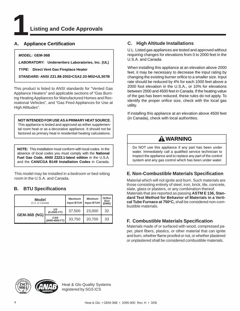
A. Appliance Certification
NOTE: This installation must conform with local codes. In theabsence of local codes you must comply with the NationalFuel Gas Code, ANSI Z223.1-latest edition in the U.S.A.and the CAN/CGA B149 Installation Codes in Canada.
NOT INTENDED FOR USE AS A PRIMARY HEAT SOURCE.This appliance is tested and approved as either supplemen-tal room heat or as a decorative appliance. It should not befactored as primary heat in residential heating calculations.
Listing and Code Approvals
C. High Altitude InstallationsU.L. Listed gas appliances are tested and approved withoutrequiring changes for elevations from 0 to 2000 feet in theU.S.A. and Canada.
When installing this appliance at an elevation above 2000feet, it may be necessary to decrease the input rating bychanging the existing burner orifice to a smaller size. Inputrate should be reduced by 4% for each 1000 feet above a2000 foot elevation in the U.S.A., or 10% for elevationsbetween 2000 and 4500 feet in Canada. If the heating valueof the gas has been reduced, these rules do not apply. Toidentify the proper orifice size, check with the local gasutility.
If installing this appliance at an elevation above 4500 feet(in Canada), check with local authorities.
B. BTU Specifications
1MODEL: GEM-36B
LABORATORY: Underwriters Laboratories, Inc. (UL)
TYPE: Direct Vent Gas Fireplace Heater
STANDARD: ANSI Z21.88-2002•CSA2.33-M02•UL307B
Model(U.S. or Canada)
MaximumInput BTUH
MinimumInput BTUH
OrificeSize
(DMS)
GEM-36B (NG)US
(0-2000 FT) 37,500 23,000 32
CAN(2000-4500 FT) 33,750 20,700 33
WARNINGDo NOT use this appliance if any part has been underwater. Immediately call a qualified service technician toinspect the appliance and to replace any part of the controlsystem and any gas control which has been under water.
This product is listed to ANSI standards for “Vented GasAppliance Heaters” and applicable sections of “Gas Burn-ing Heating Appliances for Manufactured Homes and Rec-reational Vehicles”, and “Gas Fired Appliances for Use atHigh Altitudes”.
Heat & Glo Quality Systemsregistered by SGS ICS
This model may be installed in a bedroom or bed-sittingroom in the U.S.A. and Canada.
E. Non-Combustible Materials SpecificationMaterial which will not ignite and burn. Such materials arethose consisting entirely of steel, iron, brick, tile, concrete,slate, glass or plasters, or any combination thereof.Materials that are reported as passing ASTM E 136, Stan-dard Test Method for Behavior of Materials in a Verti-cal Tube Furnace at 750oC, shall be considered non-com-bustible materials.
F. Combustible Materials SpecificationMaterials made of or surfaced with wood, compressed pa-per, plant fibers, plastics, or other material that can igniteand burn, whether flame proofed or not, or whether plasteredor unplastered shall be considered combustible materials.

Heat & Glo • GEM-36B • 2095-900 Rev. H • 3/06 5
For all side wall horizontally vented gas fueled equipmentinstalled in every dwelling, building or structure used inwhole or in part for residential purposes, including thoseowned or operated by the Commonwealth and where theside wall exhaust vent termination is less than seven (7)feet above finished grade in the area of the venting, includ-ing but not limited to decks and porches, the following re-quirements shall be satisfied:
Installation of Carbon Monoxide DetectorsAt the time of installation of the side wall horizontal ventedgas fueled equipment, the installing plumber or gasfittershall observe that a hard wired carbon monoxide detectorwith an alarm and battery back-up is installed on the floorlevel where the gas equipment is to be installed. In addi-tion, the installing plumber or gasfitter shall observe that abattery operated or hard wired carbon monoxide detectorwith an alarm is installed on each additional level of thedwelling, building or structure served by the side wall hori-zontal vented gas fueled equipment. It shall be the respon-sibility of the property owner to secure the services of qual-ified licensed professionals for the installation of hard wiredcarbon monoxide detectors.
In the event that the side wall horizontally vented gas fu-eled equipment is installed in a crawl space or an attic, thehard wired carbon monoxide detector with alarm and bat-tery back-up may be installed on the next adjacent floorlevel.In the event that the requirements of this subdivision cannot be met at the time of completion of installation, theowner shall have a period of thirty (30) days to comply withthe above requirements; provided, however, that during saidthirty (30) day period, a battery operated carbon monoxidedetector with an alarm shall be installed.
Approved Carbon Monoxide DetectorsEach carbon monoxide detector as required in accordancewith the above provisions shall comply with NFPA 720 andbe ANSI/UL 2034 listed and IAS certified.
SignageA metal or plastic identification plate shall be permanentlymounted to the exterior of the building at a minimum heightof eight (8) feet above grade directly in line with the ex-haust vent terminal for the horizontally vented gas fueledheating appliance or equipment. The sign shall read, inprint size no less than one-half (1/2) inch in size, “GASVENT DIRECTLY BELOW. KEEP CLEAR OF ALL OB-STRUCTIONS”.
InspectionThe state or local gas inspector of the side wall horizontallyvented gas fueled equipment shall not approve the installa-tion unless, upon inspection, the inspector observes car-bon monoxide detectors and signage installed in accordancewith the provisions of 248 CMR 5.08(2)(a)1 through 4.
ExemptionsThe following equipment is exempt from 248 CMR 5.08(2)(a)1through 4:
• The equipment listed in Chapter 10 entitled “EquipmentNot Required To Be Vented” in the most current editionof NFPA 54 as adopted by the Board; and
• Product Approved side wall horizontally vented gas fu-eled equipment installed in a room or structure separatefrom the dwelling, building or structure used in whole orin part for residential purposes.
MANUFACTURER REQUIREMENTS
Gas Equipment Venting System Provided
When the manufacturer of Product Approved side wall hori-zontally vented gas equipment provides a venting systemdesign or venting system components with the equipment,the instructions provided by the manufacturer for installa-tion of the equipment and the venting system shall include:
• Detailed instructions for the installation of the ventingsystem design or the venting system components; and
• A complete parts list for the venting system design orventing system.
Gas Equipment Venting System NOT Provided
When the manufacturer of a Product Approved side wallhorizontally vented gas fueled equipment does not providethe parts for venting the flue gases, but identifies “specialventing systems”, the following requirements shall be sat-isfied by the manufacturer:
• The referenced “special venting system” instructions shallbe included with the appliance or equipment installationinstructions; and
• The “special venting systems” shall be Product Approvedby the Board, and the instructions for that system shallinclude a parts list and detailed installation instructions.
A copy of all installation instructions for all Product Approvedside wall horizontally vented gas fueled equipment, all vent-ing instructions, all parts lists for venting instructions, and/or all venting design instructions shall remain with the ap-pliance or equipment at the completion of the installation.
See Gas Connection section for additional Common-wealth of Massachusetts requirements.
NOTE: The following requirements reference variousMassachusetts and national codes not contained inthis document.
G. Requirements for the Commonwealth ofMassachusetts
Heat & Glo • GEM-36B • 2095-900 Rev. H • 3/066
A. Design and Installation ConsiderationsHeat & Glo direct vent gas appliances are designed to op-erate with all combustion air siphoned from outside of thebuilding and all exhaust gases expelled to the outside. Noadditional outside air source is required.
Getting Started
C. Inspect Appliance and Components
2
When planning an appliance installation, it’s necessary todetermine the following information before installing:
• Where the appliance is to be installed.
• The vent system configuration to be used.
• Gas supply piping.
• Electrical wiring.
• Framing and finishing details.
• Whether optional accessories—devices such as a fan,wall switch, or remote control—are desired.
B. Tools and Supplies NeededBefore beginning the installation be sure that the followingtools and building supplies are available.
Reciprocating saw Framing materialPliers Hi temp caulking materialHammer GlovesPhillips screwdriver Framing squareFlat blade screwdriver Electric drill and bits (1/4 in.)Plumb line Safety glassesLevel 1/2 - 3/4 inch length, #6 or #8 Self-drilling screwsManometer VoltmeterTape measure Noncorrosive leak check solutionOne 1/4 inch female connection (for optional fan).
• Carefully remove the appliance and components fromthe packaging.
• The vent system components and trim doors are shippedin separate packages.
• The gas logs may be packaged separately and must befield installed.
• Report to your dealer any parts damaged in shipment,particularly the condition of the glass.
• Read all of the instructions before starting the in-stallation. Follow these instructions carefully dur-ing the installation to ensure maximum safety andbenefit.
Check building codes prior to installation.• Installation MUST comply with local, regional, state
and national codes and regulations.• Consult local building, fire officials or authorities
having jurisdiction about restrictions, installationinspection, and permits.
CAUTION
Keep appliance dry.• Mold or rust may cause odors.• Water may damage controls.
WARNING
Inspect appliance and components fordamage. Damaged parts may impair safeoperation.
WARNING
• Do NOT install damaged components.• Do NOT install incomplete components.• Do NOT install substitute components.
Report damaged parts to dealer.
Hearth & Home Technologies disclaimsany responsibility for, and the warranty willbe voided by, the following actions:
WARNING
• Installation and use of any damaged appliance or ventsystem component.
• Modification of the appliance or vent system.
• Installation other than as instructed by Hearth & HomeTechnologies.
• Improper positioning of the gas logs or the glass door.
• Installation and/or use of any component part notapproved by Hearth & Home Technologies.
Any such action may cause a fire hazard.
Heat & Glo • GEM-36B • 2095-900 Rev. H • 3/06 7
3 Framing and Clearances
NOTE:• Illustrations reflect typical installations and are FOR
DESIGN PURPOSES ONLY.• Illustrations/diagrams are not drawn to scale.• Actual installation may vary due to individual design
preference.
WARNINGFire RiskProvide adequate clearance:• Around air openings• To combustibles• For service accessLocate appliance away from traffic areas.
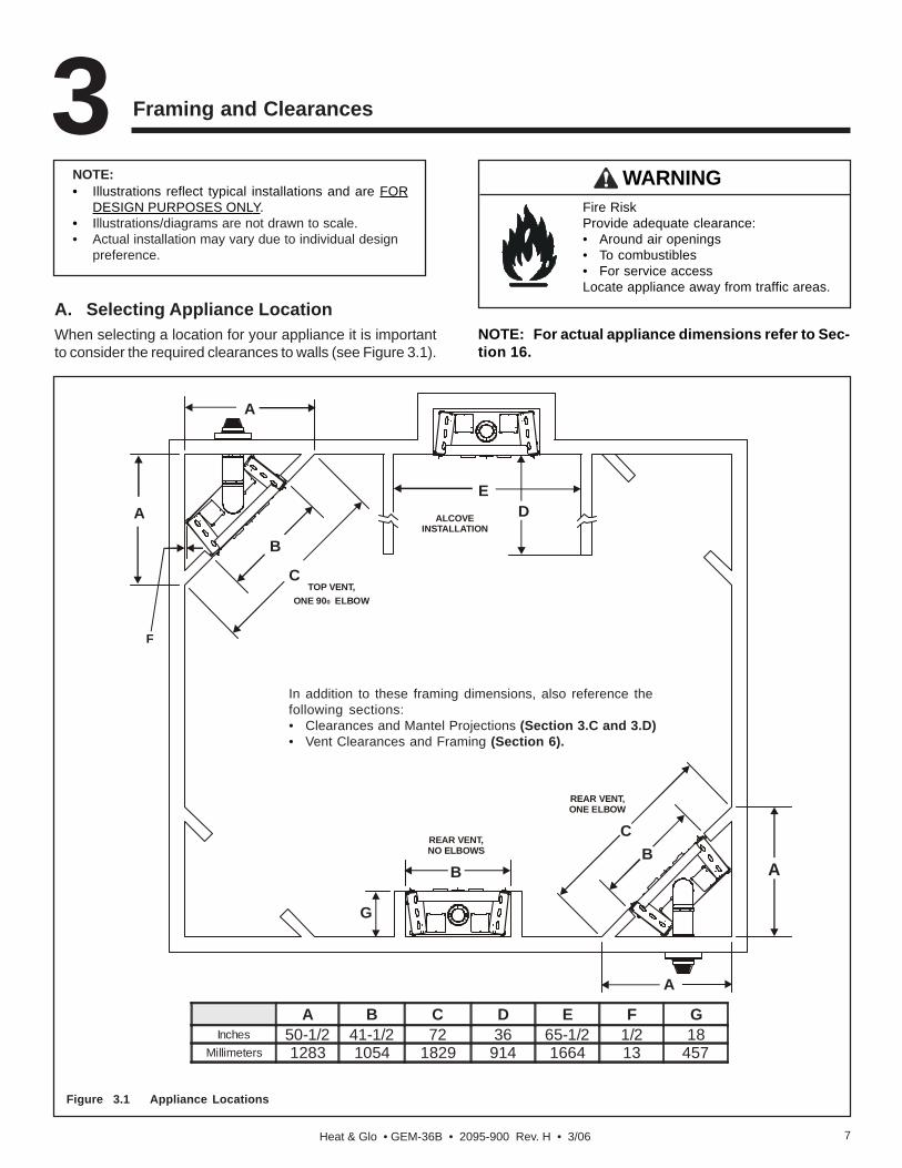
A. Selecting Appliance LocationWhen selecting a location for your appliance it is importantto consider the required clearances to walls (see Figure 3.1).
Figure 3.1 Appliance Locations
A B C D E F GInches 50-1/2 41-1/2 72 36 65-1/2 1/2 18
Millimeters 1283 1054 1829 914 1664 13 457
NOTE: For actual appliance dimensions refer to Sec-tion 16.
In addition to these framing dimensions, also reference thefollowing sections:• Clearances and Mantel Projections (Section 3.C and 3.D)• Vent Clearances and Framing (Section 6).
A
A
F
CTOP VENT,
ONE 90 ELBOW0
B
DE
ALCOVEINSTALLATION
A
C
REAR VENT,ONE ELBOW
B
A
REAR VENT,NO ELBOWS
B
G

Heat & Glo • GEM-36B • 2095-900 Rev. H • 3/068
B. Constructing the Appliance ChaseA chase is a vertical boxlike structure built to enclose thegas appliance and/or its vent system. Vertical vents thatrun on the outside of a building may be, but are not re-quired to be, installed inside a chase.
Construction of the chase may vary with the type of building.These instructions are not substitutes for the requirements oflocal building codes. Local building codes MUST be checked.
Chases should be constructed in the manner of all outsidewalls of the home to prevent cold air drafting problems.The chase should not break the outside building envelopein any manner.
Walls, ceiling, base plate and cantilever floor of the chaseshould be insulated. Vapor and air infiltration barriers shouldbe installed in the chase as per regional codes for the restof the home. Additionally, in regions where cold air infiltra-tion may be an issue, the inside surfaces may be sheetrockedand taped for maximum air tightness.
To further prevent drafts, the wall shield and ceiling firestopsshould be caulked with high temperature caulk to seal gaps.Gas line holes and other openings should be caulked with
C. Clearances
Figure 3.2 Clearances to Combustibles
Fire Risk.Odor Risk.• Install appliance on hard metal or wood
surfaces extending full width and depth ofappliance.
• Do NOT install appliance directly oncarpeting, vinyl, tile or any combustiblematerial other than wood.
WARNING
CLEARANCES TO COMBUSTIBLES:
A B C D E F G H I JRough
Opening (Vent Pipe)
RoughOpening(Height)
RoughOpening(Depth)
RoughOpening(Width)
Clearance toCeiling from Topof Arch Opening
Non-CombustibleFloor
CombustibleFlooring
BehindAppliance
Sides ofAppliance
Front ofAppliance
Inches 10 43 17-1/2 41-1/2 37-1/8 0 8 1/2 1/2 36mm 254 1092 445 1054 943 0 203 13 13 914
Fire Risk.• Construct chase to all clearance
specifications in manual.• Locate and install appliance to all
clearance specifications in manual
WARNING
high temp caulk or stuffed with unfaced insulation. If theappliance is being installed on a cement slab, a layer ofplywood may be placed underneath to prevent conductingcold up into the room.
F
E
J
HI
FROM TOP OF ARCHOPENING TO CEILING
G
A
B
C
D
Heat & Glo • GEM-36B • 2095-900 Rev. H • 3/06 9
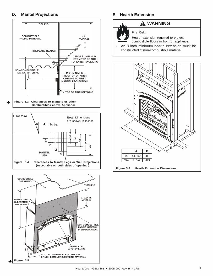
D. Mantel Projections
Figure 3.4 Clearances to Mantel Legs or Wall Projections (Acceptable on both sides of opening.)
½ in.
5
321
MANTELLEG
Top View
41
23
45
Note: Dimensionsare shown in inches.
Fire Risk.
Hearth extension required to protectcombustible floors in front of appliance.
WARNING
• An 8 inch minimum hearth extension must beconstructed of non-combustible material.
E. Hearth Extension
A
B
Figure 3.6 Hearth Extension Dimensions
A Bin. 41-1/2 8
mm 1054 203
Figure 3.5
1 in.BOTTOM OF FIREPLACE TO BOTTOMOF NON-COMBUSTIBLE FACING MATERIAL
37-1/8 in. MIN.CLEARANCETO CEILING
COMBUSTIBLESHEATHING
CEILING
FIREPLACEARCH OPENING
NON-COMBUSTIBLEFACING MATERIALIN SHADED AREAS
17-1/16 in.MINIMUM
Figure 3.3 Clearances to Mantels or other Combustibles above Appliance
NON-COMBUSTIBLEFACING MATERIAL
COMBUSTIBLEFACING MATERIAL
1 in.TYPICAL
13 in. MINIMUMFROM TOP OF ARCHOPENING TO FIRST
MANTEL PROJECTION
37-1/8 in. MINIMUMFROM TOP OF ARCHOPENING TO CEILING
FIREPLACE HEADER
1"2"
3"4"
5"6"
7"8"
9"10"
11"12"
TOP OF ARCH OPENING
CEILING

Heat & Glo • GEM-36B • 2095-900 Rev. H • 3/0610
A. Vent Termination Minimum Clearances
Fire Risk.Explosion Risk.Maintain vent clearance to combustiblesas specified.
WARNING
• Do not pack air space with insulation orother materials.
Failure to keep insulation or other materialsaway from vent pipe may cause fire.
Roof Pitch H (Min.) Ft.Flat to 6/12 .......................................................... 1.0*Over 6/12 to 7/12 ............................................... 1.25*Over 7/12 to 8/12 ............................................... 1.5*Over 8/12 to 9/12 ............................................... 2.0*Over 9/12 to 10/12 ............................................. 2.5Over 10/12 to 11/12 ........................................... 3.25Over 11/12 to 12/12 ........................................... 4.0Over 12/12 to 14/12 ........................................... 5.0Over 14/12 to 16/12 ........................................... 6.0Over 16/12 to 18/12 ........................................... 7.0Over 18/12 to 20/12 ........................................... 7.5Over 20/12 to 21/12 ........................................... 8.0
Figure 4.1Figure 4.2 Minimum Height from Roof to Lowest Discharge Opening
Termination Locations4
Measure horizontal clearances from this surface.
Measure vertical clearances from this surface.
Figure 4.3 Multiple Vertical Termination
Figure 4.2 specifies minimum vent heights for variouspitched roofs.
(See Figure 4.4 for specific clearances)* 3 foot minimum in snow regions
GAS, WOOD or FUELOIL TERMINATION 20 IN.
(MINIMUM) TOPERPENDICULARWALL (GAS ONLY)
18 IN.
A
GASTERMINATION
Gas Termination Wood & Fuel Oil TerminationA 6 in. 20 in.
HORIZONTALOVERHANG
VERTICALWALL
TERMINATIONCAP
12X
ROOF PITCHIS X/ 12
LOWEST DISCHARGE
OPENING
H (MIN.) - MINIMUM HEIGHT FROM ROOFTO LOWEST DISCHARGE OPENING
2 FT.MIN.
20 INCHES
Heat & Glo • GEM-36B • 2095-900 Rev. H • 3/06 11
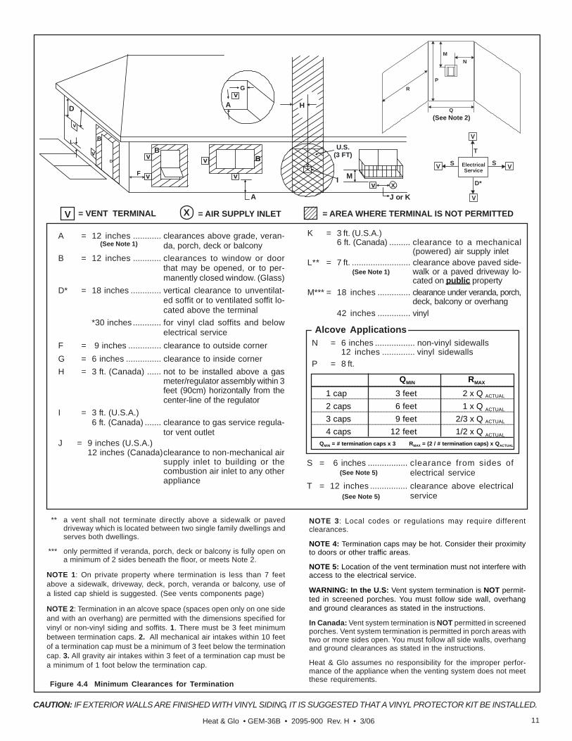
V = VENT TERMINAL X = AIR SUPPLY INLET = AREA WHERE TERMINAL IS NOT PERMITTED
Figure 4.4 Minimum Clearances for Termination
A = 12 inches ............ clearances above grade, veran-da, porch, deck or balcony
B = 12 inches ............ clearances to window or doorthat may be opened, or to per-manently closed window. (Glass)
D* = 18 inches ............. vertical clearance to unventilat-ed soffit or to ventilated soffit lo-cated above the terminal
*30 inches ............ for vinyl clad soffits and belowelectrical service
F = 9 inches .............. clearance to outside cornerG = 6 inches ............... clearance to inside cornerH = 3 ft. (Canada) ...... not to be installed above a gas
meter/regulator assembly within 3feet (90cm) horizontally from thecenter-line of the regulator
I = 3 ft. (U.S.A.)6 ft. (Canada) ....... clearance to gas service regula-
tor vent outletJ = 9 inches (U.S.A.)
12 inches (Canada)clearance to non-mechanical airsupply inlet to building or thecombustion air inlet to any otherappliance
K = 3 ft. (U.S.A.)6 ft. (Canada) ......... clearance to a mechanical
(powered) air supply inletL** = 7 ft. ......................... clearance above paved side-
walk or a paved driveway lo-cated on public property
M*** = 18 inches .............. clearance under veranda, porch,deck, balcony or overhang
42 inches .............. vinyl
CAUTION: IF EXTERIOR WALLS ARE FINISHED WITH VINYL SIDING, IT IS SUGGESTED THAT A VINYL PROTECTOR KIT BE INSTALLED.
** a vent shall not terminate directly above a sidewalk or paveddriveway which is located between two single family dwellings andserves both dwellings.
*** only permitted if veranda, porch, deck or balcony is fully open ona minimum of 2 sides beneath the floor, or meets Note 2.
NOTE 1: On private property where termination is less than 7 feetabove a sidewalk, driveway, deck, porch, veranda or balcony, use ofa listed cap shield is suggested. (See vents components page)
NOTE 2: Termination in an alcove space (spaces open only on one sideand with an overhang) are permitted with the dimensions specified forvinyl or non-vinyl siding and soffits. 1. There must be 3 feet minimumbetween termination caps. 2. All mechanical air intakes within 10 feetof a termination cap must be a minimum of 3 feet below the terminationcap. 3. All gravity air intakes within 3 feet of a termination cap must bea minimum of 1 foot below the termination cap.
MN
PR
Q
(See Note 1)
(See Note 1)
(See Note 2)
ElectricalService
V
SV S
V
T
D*
V
NOTE 3: Local codes or regulations may require differentclearances.
NOTE 4: Termination caps may be hot. Consider their proximityto doors or other traffic areas.
NOTE 5: Location of the vent termination must not interfere withaccess to the electrical service.
WARNING: In the U.S: Vent system termination is NOT permit-ted in screened porches. You must follow side wall, overhangand ground clearances as stated in the instructions.
In Canada: Vent system termination is NOT permitted in screenedporches. Vent system termination is permitted in porch areas withtwo or more sides open. You must follow all side walls, overhangand ground clearances as stated in the instructions.
Heat & Glo assumes no responsibility for the improper perfor-mance of the appliance when the venting system does not meetthese requirements.
DE
BL
v
v v
v
v
v
v
v
BB
A H
MX
J or K
I
A
G
F
U.S.(3 FT)B
S = 6 inches ................. clearance from sides ofelectrical service
T = 12 inches ................ clearance above electricalservice
(See Note 5)
(See Note 5)
______________________________________________________________________
______________________________________________________________________
______________________________________________________________________
______________________________________________________________________
QMIN RMAX
1 cap 3 feet 2 x Q ACTUAL
2 caps 6 feet 1 x Q ACTUAL
3 caps 9 feet 2/3 x Q ACTUAL
4 caps 12 feet 1/2 x Q ACTUAL
QMIN = # termination caps x 3 RMAX = (2 / # termination caps) x QACTUAL
N = 6 inches ................. non-vinyl sidewalls12 inches .............. vinyl sidewalls
P = 8 ft.
Alcove Applications

Heat & Glo • GEM-36B • 2095-900 Rev. H • 3/0612
5 Vent Information and Diagrams
Fire Hazard.Explosion Risk.Asphyxiation Risk.Do NOT connect this gas appliance to achimney flue serving a separate solid-fuel orgas burning appliance.• Vent this appliance directly outside.• Use separate vent system for this
appliance.May impair safe operation of this appliance orother appliances connected to the flue.
WARNING
CAUTIONALL vent configuration specifications MUST be followed.• This product is tested and listed to these
specifications.• Appliance performance will suffer if specifications are
not followed.
B. Use of Elbows
Diagonal runs have both vertical and horizontal vent as-pects when calculating the effects. Use the rise for the ver-tical aspect and the run for the horizontal aspect (see Fig-ure 5.1).
Two 450 elbows may be used in place of one 900 elbow. On450 runs, one foot of diagonal is equal to 8.5 inches hori-zontal run and 8.5 inches vertical run. A length of straightpipe is allowed between two 450 elbows (see Figure 5.1).
Figure 5.1
A. Vent Table KeyThe abbreviations listed in this vent table key are used inthe vent diagrams.
Symbol Description
V1 First section (closest to appliance) of vertical length
V2 Second section of vertical length
H1 First section (closest to appliance) of horizontal length
H2 Second section of horizontal length
C. Measuring StandardsVertical and horizontal measurements listed in the ventdiagrams were made using the following standards.
1. Pipe measurements are shown using the effective lengthof pipe (see Figure 5.2).
2. Measurements are made from the appliance outer wrap,not from the standoffs.
3. Horizontal terminations are measured to the outsidemounting surface (flange of termination cap) (see Fig-ure 4.1).
4. Vertical terminations are measured to bottom of termi-nation cap.
5. Horizontal pipe installed level with no rise.
Figure 5.2 DVP Pipe Effective Length
EffectiveHeight/Length
DVP4 4DVP6 6DVP12 12DVP24 24DVP36 36DVP48 48DVP6A 3 to 6DVP12A 3 to 12DVP12MI 3 to 12DVP24MI 3 to 24
Length/InchesPipe
DVP PIPE
Horizontal
Vertical
8-1/2 in.
8-1/
2iN
.
12in.

Heat & Glo • GEM-36B • 2095-900 Rev. H • 3/06 13
Figure 5.3
Figure 5.4
D. Vent Diagrams
Fire Risk. Explosion Risk.Do NOT pack insulation or other combustibles between ceiling firestops.• ALWAYS maintain specified clearances around venting and firestop systems.• Install wall shield and ceiling firestops as specified.Failure to keep insulation or other material away from vent pipe may cause fire.
WARNING
1. Top Vent - Horizontal Termination
One Elbow
Two Elbows
V1 Minimum H1 Maximum1 ft 305 mm 2 ft 610 mm2 ft 610 mm 5 ft 1.5 m3 ft 914 mm 8 ft 2.4 m4 ft 1.2 m 11 ft 3.4 m5 ft 1.5 m 14 ft 4.3 m6 ft 1.8 m 17 ft 5.2 m7 ft 2.1 m 20 ft 6.1 m8 ft 2.4 m 23 ft 7.0 m
V1 = 40 ft (12.2m) MaximumH1 = 23 ft (7.0 m) Maximum
V1 + H1 = 63 ft (19.2m) Maximum
V1
H1
V1 Minimum H1 + H1Maximum
1 ft 305 mm 2 ft 610 mm2 ft 610 mm 5 ft 1.5 m3 ft 914 mm 8 ft 2.4 m4 ft 1.2 m 11 ft 3.4 m5 ft 1.5 m 14 ft 4.3 m6 ft 1.8 m 17 ft 5.2 m7 ft 2.1 m 20 ft 6.1 m8 ft 2.4 m 23 ft 7.0 m
V1 + H1 + H2= 63 ft (19.2 m) MaximumH1 + H2 = 23 ft (7.0 m) Maximum
NOTE: Must have a one foot minimumvertical vent before attaching a 90o
elbow to the unit.
NOTE: Must have a one foot minimumvertical vent before attaching a 90o elbowto the unit.
H2 H1
V1
INSTALLEDHORIZONTALLY

Heat & Glo • GEM-36B • 2095-900 Rev. H • 3/0614
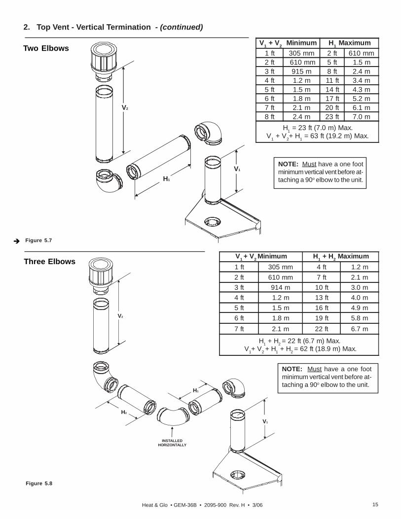
Figure 5.5
1. Top Vent - Horizontal Termination - (continued)
Three ElbowsV1 Minimum H1 + H2 Maximum
1 ft 305 mm 4 ft 1.2 m2 ft 607 mm 7 ft 2.1 m3 ft 914 mm 10 ft 3.0 m4 ft 1.2 m 13 3.4 m5 ft 1.5 m 16 4.9 m6 ft 1.8 m 17 5.2 m7 ft 2.1m 22 6.7 m
H1 + H2 = 22 ft (6.7 m) Max. V1+ V2 + H1 + H2 = 62 ft (18.9 m) Max.
H1
V2
H2
V1
NOTE: Must have a one foot minimumvertical vent before attaching a 90o elbowto the unit.
Figure 5.6
V1 = 40 FT MAX. (12.4 M)
NOTE: On vertical venting config-urations install the vertical bafflefound in the appliance to the left ofthe control panel. Follow flue re-strictor instructions in Section 7B.
Straight Up Vertical Venting
2. Top Vent - Vertical Termination CAP
V1
Heat & Glo • GEM-36B • 2095-900 Rev. H • 3/06 15
2. Top Vent - Vertical Termination - (continued)
Three ElbowsV1 + V2 Minimum H1 + H2 Maximum1 ft 305 mm 4 ft 1.2 m2 ft 610 mm 7 ft 2.1 m3 ft 914 m 10 ft 3.0 m4 ft 1.2 m 13 ft 4.0 m5 ft 1.5 m 16 ft 4.9 m6 ft 1.8 m 19 ft 5.8 m7 ft 2.1 m 22 ft 6.7 m
H1 + H2 = 22 ft (6.7 m) Max. V1+ V2 + H1 + H2 = 62 ft (18.9 m) Max.
NOTE: Must have a one footminimum vertical vent before at-taching a 90o elbow to the unit.
Figure 5.8
H1
V2
H2
V1
INSTALLEDHORIZONTALLY
Figure 5.7
Two ElbowsV1 + V2 Minimum H1 Maximum
1 ft 305 mm 2 ft 610 mm2 ft 610 mm 5 ft 1.5 m3 ft 915 m 8 ft 2.4 m4 ft 1.2 m 11 ft 3.4 m5 ft 1.5 m 14 ft 4.3 m6 ft 1.8 m 17 ft 5.2 m7 ft 2.1 m 20 ft 6.1 m8 ft 2.4 m 23 ft 7.0 m
H1 = 23 ft (7.0 m) Max.V1 + V2+ H1 = 63 ft (19.2 m) Max.
V1
H1
V2
NOTE: Must have a one footminimum vertical vent before at-taching a 90o elbow to the unit.

Heat & Glo • GEM-36B • 2095-900 Rev. H • 3/0616
A. Pipe Clearances to Combustibles
Vent Clearances and Framing6
Combustible Wall PenetrationFrame a hole in a combustible wall for an interior wall shieldfirestop, (Figure 6.2) whenever a wall is penetrated. Usesame size framing materials as those used in the wall con-struction. The wall shield firestop maintains minimum clear-ances and prevents cold air infiltration.
Non-Combustible Wall PenetrationIf the hole being penetrated is surrounded by noncombusti-ble materials such as concrete, a hole with diameter oneinch greater than the pipe is acceptable.
Fire Risk.Explosion Risk.Maintain vent clearance to combustiblesas specified.
WARNING
• Do not pack air space with insulation orother materials.
Failure to keep insulation or other materialsaway from vent pipe may cause fire.
B. Wall Penetration Framing
Figure 6.1 Pipe Clearances
1 in. CLEARANCEAROUND VERTICAL
SECTIONS
3 in. TOPCLEARANCE
1 in. SIDE ANDBOTTOM CLEARANCE
Figure 6.2 Exterior Wall Hole
A* B 22 -15/16 in. 54-1/2 in.
* Heat-Out framing is 12 inches wide by 10 inches tall, oppo-site of vent framing. Center of Heat-Out framing is 1-1/16inch LOWER than the center of the Heat-Out pipe.
Figure 6.2 Horizontal Venting Clearances to Combustible Materials
NOTE: Slopenot required.
BA*
HEAT-OUT
10 in.(Width)
12 in.(Height)
Shows center of 10 inch x 12 inch vent framing holes fortop and rear venting. The center of the hole is one (1) inch(25.4mm) above the center of the horizontal vent pipe.
WALL
HEATSHIELD HEAT
SHIELD
3 in. TOPCLEARANCE
WALLSHIELD
FIRESTOP
1 in. CLEARANCEBOTTOM & SIDES

Heat & Glo • GEM-36B • 2095-900 Rev. H • 3/06 17
C. Vertical Penetration Framing
Installing the Ceiling Firestop
• Frame an opening 10 inches by 10 inch-es whenever the vent system pene-trates a ceiling/floor (see Figure 6.3).
• Frame the area with the same sized lum-ber as used in ceiling/floor joist.
• When installing a top vent vertical termi-nation appliance the hole should be di-rectly above the appliance, unless theflue is offset.
• Do not pack insulation around the vent.Insulation must be kept away from thepipe.
Figure 6.3
ATTICABOVE
A
B
WARNINGFire Hazard
Keep loose materials orblown insulation from touch-ing the vent pipe.
Installing Attic Shield
Note: An additional ceiling firestop is notrequired if attic shield is used.
• Frame opening for attic shield.
• Attic shield may be installed above orbelow ceiling (see Figure 6.4).
• Secure with three fasteners on eachside.
• Fold tabs at top of attic shield in towardvent pipe. Tabs must keep vent pipecentered within shield.
• Field construct additional shield heightif insulation is deeper than height of at-tic shield.
Figure 6.4 Installing the Attic Shield
• National building codes recommend us-ing attic shield to keep loose materials/blown insulation from contacting vent.
• Hearth & Home Technologies requiresthe use of an attic shield.
A B 10 in. 10 in.DVPPIPE
3 FASTENERSPER SIDE
BEND TABS INAROUND PIPE
ATTIC SHIELD INSTALLEDBELOW CEILING
ATTIC SHIELD INSTALLEDABOVE CEILING

Heat & Glo • GEM-36B • 2095-900 Rev. H • 3/0618
Appliance Preparation7A. Removing Non-combustible Facing Material AssemblyThe non-combustible assembly is located on the back ofappliance (see Figure 7.1).
Figure 7.1 Non-Combustible Facing Material Assembly
• Hold non-combustible pieces in place.
• Remove and save two screws from both upper brackets(see Figure 7.1).
• Remove non-combustible pieces.
• Remove and save three screws from lower bracket (seeFigure 7.1).
• Remove 5 screws from upper shelf (see Figure 7.2).
• Bend sheetmetal brace away from unit (see Figure7.2) until tabs on shelf are released from standoffs.
• Remove 3 screws at bottom of sheetmetal braceand remove brace from unit.
• Discard brackets, sheetmetal brace and shelf.
• Replace screws in holes where these pieces were at-tached to appliance.
Handle with care.• Non-combustible material may be damaged if dropped.
CAUTION
Figure 7.2 Sheetmetal Brace and Shelf (rear of appliance viewed from appliance front).
Remove screwsfrom upperbrackets.
LowerBracket
A
A
A A
A
D
B
D D
Stan
doff
Standoff
Shelf
SheetmetalBrace
C C
A
BC
D

Heat & Glo • GEM-36B • 2095-900 Rev. H • 3/06 19
C. Installing Non-combustible Facing Material
WARNING
Figure 7.4 Attaching Non-combustible Facing Material
Fire Risk.• Follow these instructions exactly.• Facing materials must be installed properly
to prevent fire.• No materials may be substituted without
authorization by Hearth & HomeTechnologies.
• Center and attach top board to the framing members(see Figure 7.4).
• Use fasteners from fastener packet (in manual bag) inshaded areas (Figure 7.4).
• Use regular sheetrock screws in non-shaded areas (seeFigure 7.4).
Apply fasteners fromfastener packet in
shaded areas.
WARNINGFire Risk.• ALWAYS maintain specified
clearances around the appliance.• Do NOT notch into the framing around the appliance spacers.Failure to keep insulation, framing or other material awayfrom the appliance may cause fire.
• Place the appliance into position.
• Level the appliance from side to side and front to back.
• Shim the appliance, as necessary. It is acceptable touse wood shims.
• Bend out nailing tabs on each side.
• Keep nailing tabs flush with the framing.
• Secure the appliance to the framing by using nails or screwsthrough the nailing tabs.
Figure 7.3 Proper Positioning, Leveling and Securing of a Appliance
NAILING TABS(BOTH SIDES)
The diagram shows (Figure 7.3) the location of the nailingtabs which are provided to secure the appliance to the fram-ing members.
B. Securing and Leveling the Appliance
Fire Risk.• Prevent contact with sagging, loose
insulation.• Do NOT install against combustible
materials such as exposed insulation,plastic and insulation backer.
WARNING
CAUTIONSharp Edges• Wear protective gloves
and safety glassesduring installation.

Heat & Glo • GEM-36B • 2095-900 Rev. H • 3/0620
E. Adjusting Pilot Shield
Note: When venting this unit with high vertical (10feet or more) with very little horizontal the pilot shieldwill need to be in the closed position (see Figure 7.7).
Figure 7.7
PILOT SHIELD SHOULD BECLOSED AND TOUCHING
THE PILOT BRACKET(MORE THAN 10 FEET VERTICAL)
PILOT SHIELD
PILOTBRACKET
Figure 7.8
Note: When venting this unit with long horizontalruns and/or multiple elbows, the pilot shield will needto be in the opened position (see Figure 7.8).
PILOT SHIELD
BEND PILOT SHIELDTO ALLOW FOR
A 3/8 INCH AIR GAP(3 FEET HORIZONTAL, ORTWO OR MORE ELBOWS)
FLUERESTRICTOR
D. Installing Flue RestrictorsLocate the flue restrictors inside the unit to the left of thecontrol panel. Use the following table to determine whichrestrictors to use for the vent run.
Vent Run Vertical 15 ft. - 30 ft. 30 ft. - 40 ft.
GEM-36BNG 1-1/2 in. & 1-1/2 in. 1-1/2 in. & 1-1/4 in.
LP 1-1/2 in. & 1-1/2 in. 1-1/4 in. & 1-1/4 in.
Figure 7.6
Insert one restrictor into each of the 3 inch exhaust collars(see Figure 7.6).
FLUERESTRICTOR
• Attach the left and right side pieces to the framing mem-bers. (See Figure 7.4).
• Use a wet or dry towel or soft brush to remove dust ordirt from facing material.
• Apply a non-combustible adhesive to attach tile, stoneor other non-combustible finishing materials permanufacturer’s instructions.
Figure 7.5 Complete Installation of Non-combustible Facing Material
44 in.(1118mm)
45-3/4 in.(1162mm)
1 in.(25 mm)
NON-COMBUSTIBLEFACING
MATERIAL
Heat & Glo • GEM-36B • 2095-900 Rev. H • 3/06 21
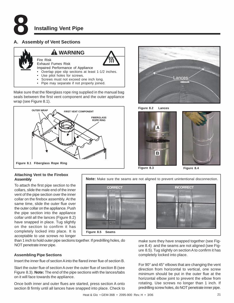
A. Assembly of Vent Sections
Installing Vent Pipe8
Assembling Pipe SectionsInsert the inner flue of section A into the flared inner flue of section B.
Start the outer flue of section A over the outer flue of section B (seeFigure 8.3). Note: The end of the pipe sections with the lances/tabson it will face towards the appliance.
Once both inner and outer flues are started, press section A ontosection B firmly until all lances have snapped into place. Check to
Attaching Vent to the FireboxAssemblyTo attach the first pipe section to thecollars, slide the male end of the innervent of the pipe section over the innercollar on the firebox assembly. At thesame time, slide the outer flue overthe outer collar on the appliance. Pushthe pipe section into the appliancecollar until all the lances (Figure 8.2)have snapped in place. Tug slightlyon the section to confirm it hascompletely locked into place. It isacceptable to use screws no longerthan 1 inch to hold outer pipe sections together. If predrilling holes, doNOT penetrate inner pipe.
Figure 8.2 Lances
Figure 8.3
A
B
Figure 8.4
Figure 8.5 Seams
Note: Make sure the seams are not aligned to prevent unintentional disconnection.
CORRECT INCORRECT
Fire RiskExhaust Fumes RiskImpaired Performance of Appliance• Overlap pipe slip sections at least 1-1/2 inches.• Use pilot holes for screws.• Screws must not exceed one inch long.• Pipe may separate if not properly joined.
WARNING
make sure they have snapped together (see Fig-ure 8.4) and the seams are not aligned (see Fig-ure 8.5). Tug slightly on section A to confirm it hascompletely locked into place.
For 90° and 45° elbows that are changing the ventdirection from horizontal to vertical, one screwminimum should be put in the outer flue at thehorizontal elbow joint to prevent the elbow fromrotating. Use screws no longer than 1 inch. Ifpredrilling screw holes, do NOT penetrate inner pipe.
Make sure that the fiberglass rope ring supplied in the manual bagseals between the first vent component and the outer appliancewrap (see Figure 8.1).
Figure 8.1 Fiberglass Rope Ring
OUTER WRAP FIRST VENT COMPONENT
FIBERGLASSROPE RING

Heat & Glo • GEM-36B • 2095-900 Rev. H • 3/0622
Assembling DVP-12A Slip Sections
The outer flue of the slip section should slide over the outerflue of the pipe section and into (inner flue) the last pipesection (see Figure 8.7) .
Slide together to the desired length, making sure that a 1-1/2 inch outer flue overlap is maintained between the pipesection and slip section.
The pipe and slip section need to be secured by driving twoscrews through the overlapping portions of the outer fluesusing the pilot holes (see Figure 8.8).
This will secure the slip section to the desired length andprevent it from separating. The slip section can then beattached to the next pipe section.
If the slip section is too long, the inner and outer flues ofthe slip section can be cut to the desired length.
Assembling Minimum Installations (MI) Sections
MI sections are non-unitized so that they can be cut to acertain length. Cut these sections to length from the non-expanded end (see Figure 8.6).
They can then be attached by first connecting the expandedend of the MI inner flue with the inner pipe from the adjacentpipe section and securing with three screws. The expandedportion of the MI inner flue must overlap completely withthe unexpanded end of the adjacent pipe section.
The outer flue can then be inserted into the adjacent outerflue expanded end and attached to the next pipe sectionwith three screws. The other end of the MI pipe sectioncan then be attached by fitting another pipe section to itand snapping it together, as normal.
Figure 8.7 Slip Section Pilot Holes
Figure 8.8 Screws into Slip Section
Figure 8.6

Heat & Glo • GEM-36B • 2095-900 Rev. H • 3/06 23
Fire Risk.Explosion Risk.Combustion Fume Risk.Use vent run supports per installationinstructions.Connect vent sections per installationinstructions.• Maintain all clearances to combustibles.• Do NOT allow vent to sag below
connection point to appliance.
WARNING
Improper support may allow vent to sag or separate.
B. Disassembly of Vent Sections
Securing the Vent Sections
Vertical SectionsVertical sections of pipe must be supported every 8 feetafter the 25 foot maximum unsupported rise. The ventsupport or plumber’s strap (spaced 120° apart) may beused to do this (see Figure 8.9).
Horizontal SectionsHorizontal sections of vent must be supported every 5 feetwith a vent support or plumber’s strap.
Figure 8.9 Securing Vertical Pipe Sections
To disassemble any two pieces of pipe, rotate either section(see Figure 8.11), so that the seams on both pipe sectionsare aligned (see Figure 8.12). They can then be carefullypulled apart.
Figure 8.12 Align and Disassemble Vent Sections
Figure 8.11 Rotate Seams for Disassembly
Figure 8.10 Securing Horizontal Pipe Sections

Heat & Glo • GEM-36B • 2095-900 Rev. H • 3/0624
C. Installing Heat Shield and Horizontal Termination Cap
NOTE: Where required, an exterior wall flashing isavailable.When penetrating a brick wall, a brick extension kitis available for framing the brick.
Heat Shield Requirements for Horizontal Termination
For all horizontally vented appliances, a heat shield MUSTbe placed one inch above the top of the vent between thewall shield firestop and the base of the termination cap.
There are two sections of the heat shield. One sectionattaches to the wall shield firestop with two screws. Theremaining section is attached to the cap in the samemanner.
If the wall thickness does not allow the required 1-1/2 inchheat shield overlap, an extended heat shield must be used.
The extended heat shield will need to be cut to the thicknessof the wall and be attached to the wall shield firestop. Thesmall leg on the extended heat shield should rest on thetop of the vent (pipe section) to properly space it from thepipe section (see Figure 8.13).
Installing the Horizontal Termination Cap
Vent termination must not be recessed in the wall. Sidingmay be brought to the edge of the cap base.
Flash and seal as appropriate for siding material at outsideedges of cap.
When installing a horizontal termination cap, follow the caplocation guidelines as prescribed by current ANSI Z223.1and CAN/CGA-B149 installation codes.
Figure 8.13 Venting through the Wall
Fire RiskExhaust Fumes RiskImpaired Performance of Appliance• Overlap pipe slip sections at least 1-1/2
inches.• Use pilot holes for screws.• Screws must not exceed 1 inch long.• Pipe may separate if not properly joined.
WARNINGBurn Risk• Local codes may require installation of
a cap shield to prevent anything oranyone from touching the hot cap.
WARNING
WARNINGFire HazardImpaired performance of appliance• Telescoping flue section of termination cap
MUST be used when connecting pipesection to termination cap.
• Maintain a 1-1/2 inch minimum overlap ontelescoping flue section of termination cap.
INNER VENT
INTERIOREXTERIOR
SHEATHING
OUTERVENT
WALL SHIELD FIRESTOP
HEAT SHIELD OREXTENDED
HEAT SHIELD
REAR VENTHEAT SHIELD
1-1/2 IN. (38MM) MIN.OVERLAP
Heat & Glo • GEM-36B • 2095-900 Rev. H • 3/06 25
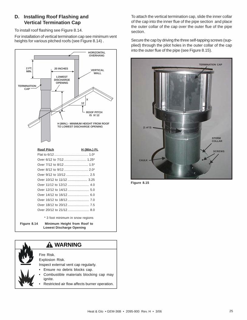
D. Installing Roof Flashing and Vertical Termination CapTo install roof flashing see Figure 8.14.For installation of vertical termination cap see minimum ventheights for various pitched roofs (see Figure 8.14) .
To attach the vertical termination cap, slide the inner collarof the cap into the inner flue of the pipe section and placethe outer collar of the cap over the outer flue of the pipesection.
Secure the cap by driving the three self-tapping screws (sup-plied) through the pilot holes in the outer collar of the capinto the outer flue of the pipe (see Figure 8.15).
Roof Pitch H (Min.) Ft.Flat to 6/12 ...................................... 1.0*Over 6/12 to 7/12 ......................... 1.25*Over 7/12 to 8/12 ........................... 1.5*Over 8/12 to 9/12 ........................... 2.0*Over 9/12 to 10/12 .......................... 2.5Over 10/12 to 11/12 ...................... 3.25Over 11/12 to 12/12 ........................ 4.0Over 12/12 to 14/12 ........................ 5.0Over 14/12 to 16/12 ........................ 6.0Over 16/12 to 18/12 ........................ 7.0Over 18/12 to 20/12 ........................ 7.5Over 20/12 to 21/12 ........................ 8.0
Figure 8.14 Minimum Height from Roof to Lowest Discharge Opening
* 3 foot minimum in snow regions
Fire Risk.Explosion Risk.Inspect external vent cap regularly.• Ensure no debris blocks cap.• Combustible materials blocking cap may
ignite.• Restricted air flow affects burner operation.
WARNING
HORIZONTALOVERHANG
VERTICALWALL
TERMINATIONCAP
12X
ROOF PITCHIS X/ 12
LOWEST DISCHARGE
OPENING
H (MIN.) - MINIMUM HEIGHT FROM ROOFTO LOWEST DISCHARGE OPENING
2 FT.MIN.
20 INCHES
Figure 8.15
SCREWS
CAULK
STORMCOLLAR
(1 of 3)
TERMINATION CAP
Heat & Glo • GEM-36B • 2095-900 Rev. H • 3/0626
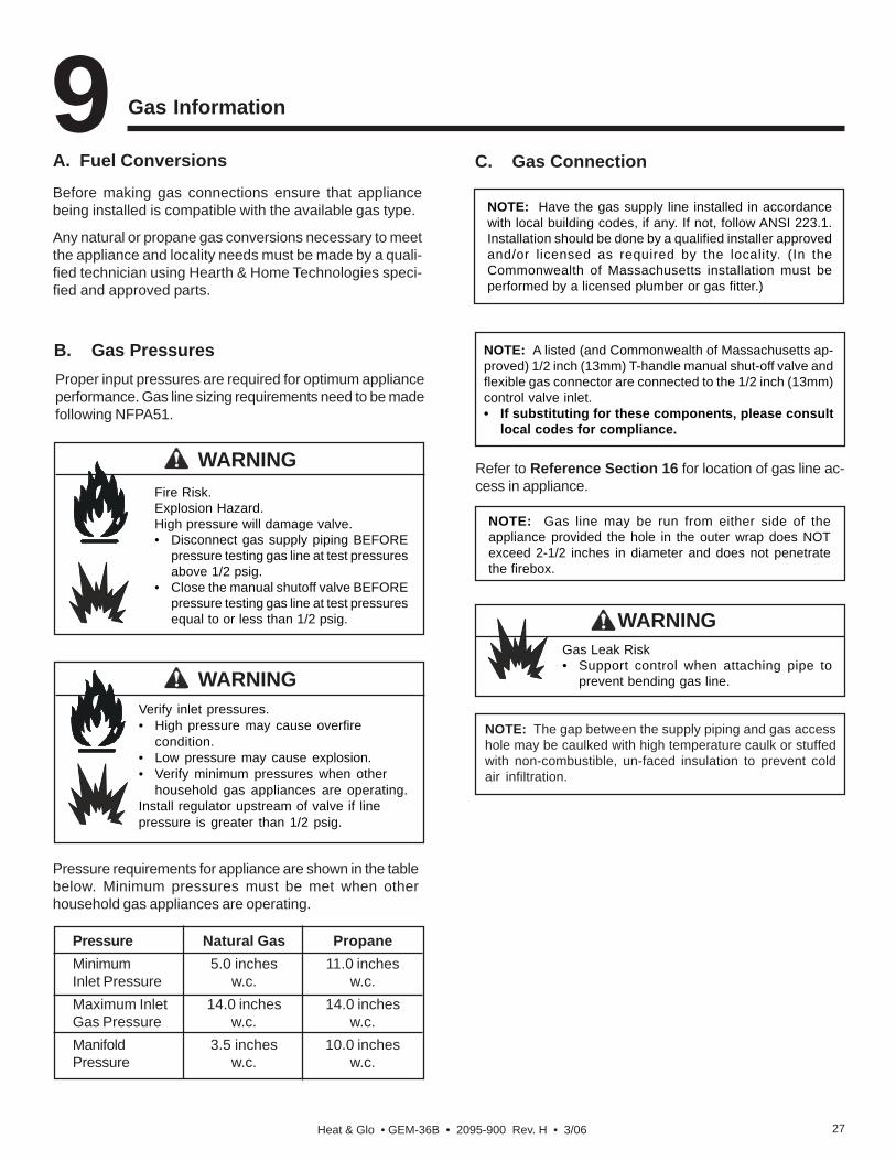
Figure 8.16 Assembling the Storm Collar
Figure 8.17 Assembling the Storm Collar Around the Pipe
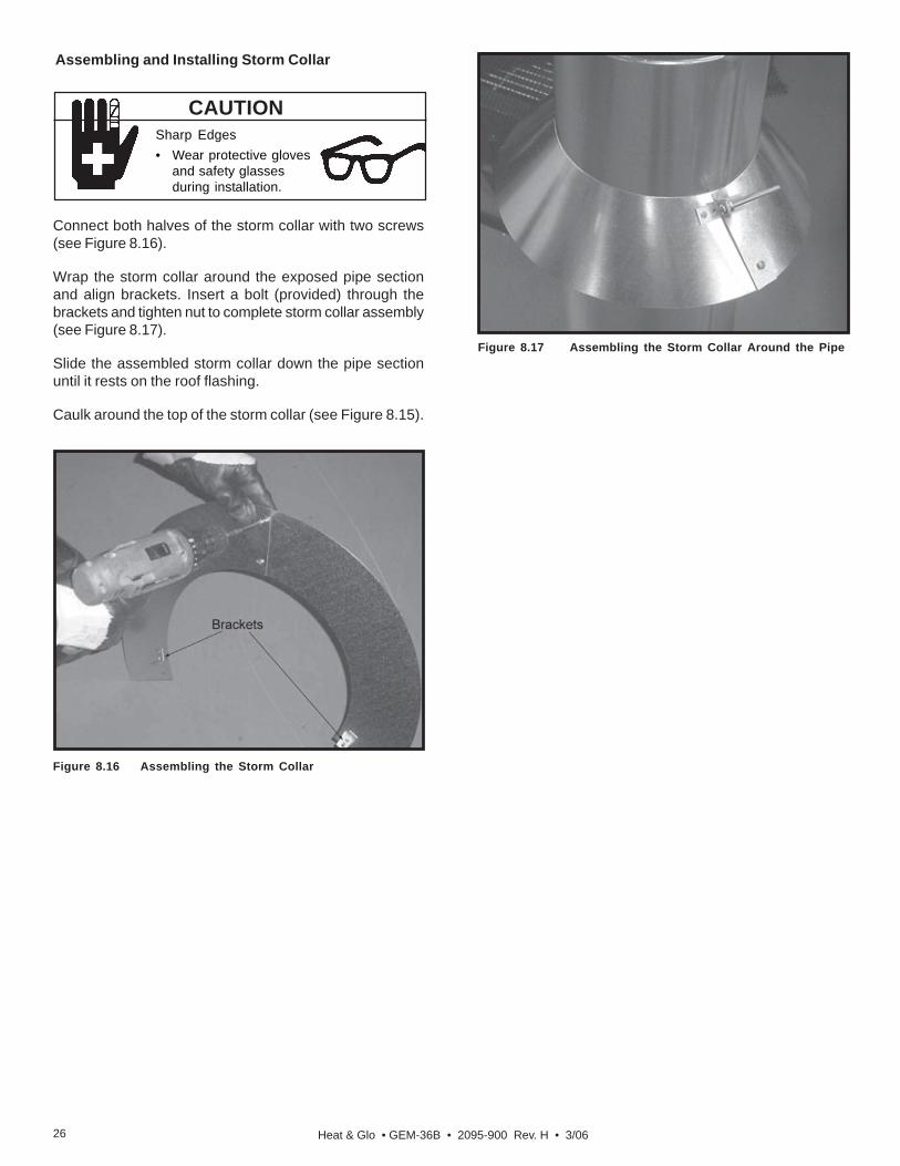
Connect both halves of the storm collar with two screws(see Figure 8.16).
Wrap the storm collar around the exposed pipe sectionand align brackets. Insert a bolt (provided) through thebrackets and tighten nut to complete storm collar assembly(see Figure 8.17).
Slide the assembled storm collar down the pipe sectionuntil it rests on the roof flashing.
Caulk around the top of the storm collar (see Figure 8.15).
CAUTIONSharp Edges• Wear protective gloves
and safety glassesduring installation.
Assembling and Installing Storm Collar
Heat & Glo • GEM-36B • 2095-900 Rev. H • 3/06 27
NOTE: Have the gas supply line installed in accordancewith local building codes, if any. If not, follow ANSI 223.1.Installation should be done by a qualified installer approvedand/or licensed as required by the locality. (In theCommonwealth of Massachusetts installation must beperformed by a licensed plumber or gas fitter.)
A. Fuel Conversions
WARNINGFire Risk.Explosion Hazard.High pressure will damage valve.• Disconnect gas supply piping BEFORE
pressure testing gas line at test pressuresabove 1/2 psig.
• Close the manual shutoff valve BEFOREpressure testing gas line at test pressuresequal to or less than 1/2 psig.
B. Gas Pressures
C. Gas Connection
WARNINGVerify inlet pressures.• High pressure may cause overfire
condition.• Low pressure may cause explosion.• Verify minimum pressures when other
household gas appliances are operating.Install regulator upstream of valve if linepressure is greater than 1/2 psig.
Proper input pressures are required for optimum applianceperformance. Gas line sizing requirements need to be madefollowing NFPA51.
Gas Information9
NOTE: Gas line may be run from either side of theappliance provided the hole in the outer wrap does NOTexceed 2-1/2 inches in diameter and does not penetratethe firebox.
NOTE: A listed (and Commonwealth of Massachusetts ap-proved) 1/2 inch (13mm) T-handle manual shut-off valve andflexible gas connector are connected to the 1/2 inch (13mm)control valve inlet.• If substituting for these components, please consult
local codes for compliance.
Pressure requirements for appliance are shown in the tablebelow. Minimum pressures must be met when otherhousehold gas appliances are operating.
Pressure Natural Gas PropaneMinimum 5.0 inches 11.0 inchesInlet Pressure w.c. w.c.Maximum Inlet 14.0 inches 14.0 inchesGas Pressure w.c. w.c.Manifold 3.5 inches 10.0 inchesPressure w.c. w.c.
Before making gas connections ensure that appliancebeing installed is compatible with the available gas type.
Any natural or propane gas conversions necessary to meetthe appliance and locality needs must be made by a quali-fied technician using Hearth & Home Technologies speci-fied and approved parts.
Refer to Reference Section 16 for location of gas line ac-cess in appliance.
WARNINGGas Leak Risk• Support control when attaching pipe to
prevent bending gas line.
NOTE: The gap between the supply piping and gas accesshole may be caulked with high temperature caulk or stuffedwith non-combustible, un-faced insulation to prevent coldair infiltration.
Heat & Glo • GEM-36B • 2095-900 Rev. H • 3/0628
WARNINGFire hazard.Do NOT change the valve settings.• This valve has been preset at the factory.• Changing valve settings may result in fire
hazard or bodily injury.
HIGH ALTITUDE INSTALLATIONSU.L. Listed gas appliances are tested and approvedwithout requiring changes for elevations from 0 to2000 feet in the U.S.A. and Canada.
When installing this appliance at an elevation above2000 feet, it may be necessary to decrease the inputrating by changing the existing burner orifice to asmaller size. Input rate should be reduced by 4% foreach 1000 feet above a 2000 foot elevation in theU.S.A., or 10% for elevations between 2000 and 4500feet in Canada. If the heating value of the gas hasbeen reduced, these rules do not apply. To identifythe proper orifice size, check with the local gas utility.
If installing this appliance at an elevation above 4500feet (in Canada), check with local authorities.
• Ensure that gas line does not come in contact with outerwrap of appliance. Follow local codes.
• Incoming gas line should be piped into the valve com-partment and connected to the 1/2 inch connection onthe manual shutoff valve.
CHECK FOR GAS LEAKSExplosion RiskFire RiskAsphyxiation Risk• Check all fittings and connections.• Do not use open flame.• After the gas line installation is complete,
all connections must be tightened andchecked for leaks with a commercially-
WARNING
WARNINGFire or Explosion Hazard• Gas buildup during line purge may ignite.• Purge should be performed by qualified technician.• Ensure adequate ventilation.• Ensure there are no ignition sources such as
sparks or open flames.
• A small amount of air will be in the gas supply lines.When first lighting appliance it will take a short time forair to purge from lines. When purging is complete theappliance will light and operate normally.
available, non-corrosive leak check solution. Be sureto rinse off all leak check solution following testing.
Fittings and connections may have loosened duringshipping and handling.

Heat & Glo • GEM-36B • 2095-900 Rev. H • 3/06 29
A. Recommendation for WireThis appliance requires 110-120 VAC be wired to the junctionbox for proper operation of the appliance. This applianceuses an Intellifire ignition system.
Electrical Information10NOTE: This appliance must be electrically wired andgrounded in accordance with local codes or, in the absenceof local codes, with National Electric Code ANSI/NFPA 70-latest edition or the Canadian Electric Code, CSA C221.1.
B. Connecting to the Appliance
WARNINGWire 110V to electrical junction box.Do NOT wire 110V to valve.Do NOT wire 110V to wall switch.• Incorrect wiring will damage millivolt valves.• Incorrect wiring will override IPI safety
lockout and may cause explosion.
Optional Accessories RequirementsWiring for optional accessories should be done now to avoidreconstruction.
CAUTIONLabel all wires prior to disconnection when servicing con-trols. Wiring errors can cause improper and dangerous op-eration. Verify proper operation after servicing.
Shock hazard.• Replace damaged wire with type 105O C
rated wire.• Wire must have high temperature insulation.
WARNING
C. Intellifire Ignition System WiringThis appliance requires a 110 VAC supply to the appliancejunction box for operation. A wiring diagram is shown inFigure 10.1.
This appliance is equipped with an Intellifire control valvewhich operates on a 3 volt system. This appliance issupplied with a battery pack which requires two D cellbatteries (not included).
CAUTIONBattery polarity must be correct or module damagewill occur.
• This appliance includes the WSK-MLT wall control. Itrequires the installation of a wall switch, to be connectedto this appliance. Please reference the WSK-MLT in-structions for specific installation and operating instruc-tions.
• Use the wire provided with this product to connect thewall switch with the receiver control, as outlined in theinstructions for the WSK-MLT control.
• Keep wire lengths short as possible by removing anyexcess wire length.
• Low voltage and 110 VAC voltage cannot be shared withinthe same wall box.

Heat & Glo • GEM-36B • 2095-900 Rev. H • 3/0630
Figure 10.1 IPI Wiring Diagram
( RED
)
( BROWN) ( BROWN)5
78
6
Blo we r
Aux CC
Set Temp
F
Fla me
CHILDPROOF
( BROWN)
1
34
2
( BROWN)
( BROWN)
SOLENOIDFLAME
FAN THERMOSTAT
ConnectionAUX ( BLACK )
Ground Pigtail Green
FANCONNECTION
Flame High / Low ACPlug
Flame On ( RED )
( RED )
( ORANGE )
( BLACK )
( ORANGE )
( RED )
( BLACK )3V DC
(YELLOW)
(YELLOW) FACTORYCONNECTED TOGETHER
FRONT VIEW
IPIValve
( ORANGE )
BLACKGROUND
( BLACK )
( RED
)
(GREEN)
MODULEIPI IPI PILOT
( BLA
CK
)
BATTERY
YG R
YELLOW(HNG) WHITE(HTL)
GREEN
RED
YR G
REAR VIEW
PILOTON/OFF
( BLACK )
( RED )
Batteries
DELAY
( BLACK )
( GREEN )
( GREEN )
( GR
EEN
)
( RED )
( RED )
( RED )
Heat & Glo • GEM-36B • 2095-900 Rev. H • 3/06 31
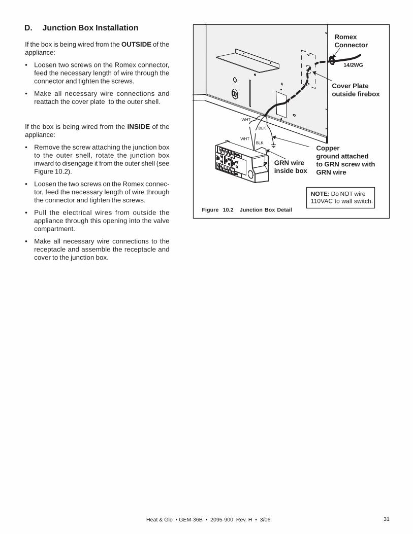
GRN wireinside box
Copperground attachedto GRN screw withGRN wire
14/2WG
Cover Plateoutside firebox
RomexConnector
WHT
WHT
BLK
BLK
D. Junction Box Installation
If the box is being wired from the OUTSIDE of theappliance:
• Loosen two screws on the Romex connector,feed the necessary length of wire through theconnector and tighten the screws.
• Make all necessary wire connections andreattach the cover plate to the outer shell.
If the box is being wired from the INSIDE of theappliance:
• Remove the screw attaching the junction boxto the outer shell, rotate the junction boxinward to disengage it from the outer shell (seeFigure 10.2).
• Loosen the two screws on the Romex connec-tor, feed the necessary length of wire throughthe connector and tighten the screws.
• Pull the electrical wires from outside theappliance through this opening into the valvecompartment.
• Make all necessary wire connections to thereceptacle and assemble the receptacle andcover to the junction box.
Figure 10.2 Junction Box Detail
NOTE: Do NOT wire110VAC to wall switch.
Heat & Glo • GEM-36B • 2095-900 Rev. H • 3/0632
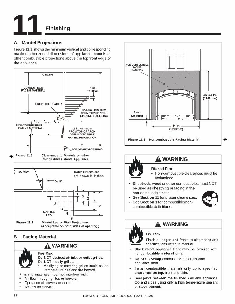
A. Mantel ProjectionsFigure 11.1 shows the minimum vertical and correspondingmaximum horizontal dimensions of appliance mantels orother combustible projections above the top front edge ofthe appliance.
Finishing
B. Facing Material
11
Figure 11.3 Noncombustible Facing Material
Fire Risk.
Finish all edges and fronts to clearances andspecifications listed in manual.
WARNING
• Black metal appliance front may be covered withnoncombustible material only.
• Do NOT overlap combustible materials ontoappliance front.
• Install combustible materials only up to specifiedclearances on top, front and side.
• Seal joints between the finished wall and appliancetop and sides using only a high temperature sealantor stove cement.
Figure 11.2 Mantel Leg or Wall Projections (Acceptable on both sides of opening.)
Figure 11.1 Clearances to Mantels or other Combustibles above Appliance
Fire Risk.Do NOT obstruct air inlet or outlet grilles.Do NOT modify grilles.• Modifying or covering grilles could cause temperature rise and fire hazard.
WARNING
Finishing materials must not interfere with:• Air flow through grilles or louvers.• Operation of louvers or doors.• Access for service.
½ in.
5
321
MANTELLEG
Top View
41
23
45
Note: Dimensionsare shown in inches.
Risk of Fire• Non-combustible clearances must be
maintained.
WARNING
• Sheetrock, wood or other combustibles must NOTbe used as sheathing or facing in thenon-combustible zone.
• See Section 11 for proper clearances.• See Section 1 for combustible/non-
combustible definitions.
44 in.(1118mm)
45-3/4 in.(1162mm)
1 in.(25 mm)
NON-COMBUSTIBLEFACING
MATERIAL
NON-COMBUSTIBLEFACING MATERIAL
COMBUSTIBLEFACING MATERIAL
1 in.TYPICAL
13 in. MINIMUMFROM TOP OF ARCHOPENING TO FIRST
MANTEL PROJECTION
37-1/8 in. MINIMUMFROM TOP OF ARCHOPENING TO CEILING
FIREPLACE HEADER
1"2"
3"4"
5"6"
7"8"
9"10"
11"12"
TOP OF ARCH OPENING
CEILING

Heat & Glo • GEM-36B • 2095-900 Rev. H • 3/06 33
C. Finishing Material RequirementsFinishing Material Thickness from 3/4 in. to 1-1/4 in.Finishing material within this thickness range can be broughtto 1/2 inch behind the door top and sides. These non-com-bustible finishing materials must never overlap or obstructthe air outlet/inlet grille areas.
Figure 11.4
Finishing Material Thickness greater than 1-1/4 inchFor finishing material greater than 1-1/4 inch a templateshould be constructed to provide the finishers with a guideto leave a 1/8 inch gap between the finishing materials andthe door. See Figure 11.5 to construct the facing template.
A steel template (GEM36-Template) is available for purchaseto use instead of constructing a template.
* Non-combustible facing material is supplied with this appliance.This material extends from the header to one inch above theappliance bottom and from framing stud to framing stud.
Figure 11.5 Facing Template Dimensions
Figure 11.6 Position of board and template
NON-COMBUSTIBLEBOARD
FACING TEMPLATE
IMPORTANT INSTALLATION NOTEPlease note that there are four holes or dots on thetemplate to assist in positioning the template. Theseholes or dots should line up with the door mountingholes on the unit to ensure proper placement of thedoor after finishing materials are installed.
44 in.
HEADER
NON-COMBUSTIBLEFINISHING MATERIAL*
45-3/4 in.
(INSTALLED OVERNON-COMBUSTIBLE FACING MATERIAL)
29-1/8 in.
21-1/2 in.3-1/8 in.
Ø3/8 in.
24-5/16 in.
1-1/4 in.
38 in.
1-1/4 in.
R39-7/8 in.
Heat & Glo • GEM-36B • 2095-900 Rev. H • 3/0634
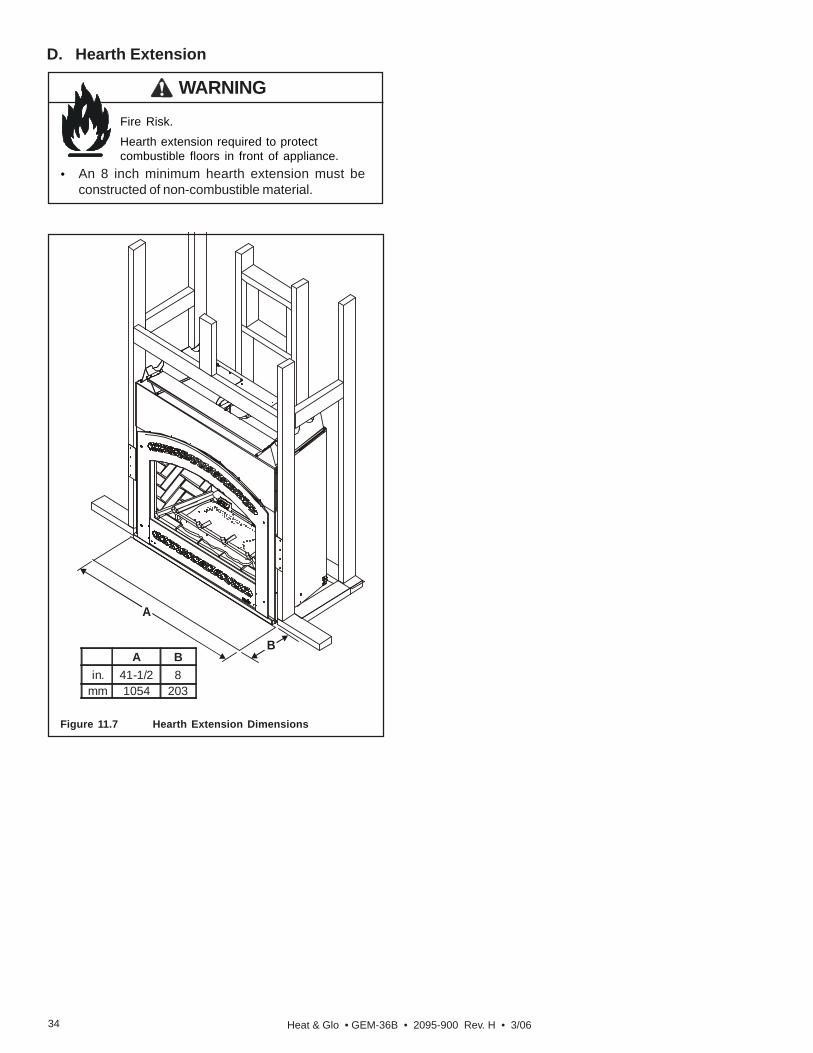
Fire Risk.
Hearth extension required to protectcombustible floors in front of appliance.
WARNING
• An 8 inch minimum hearth extension must beconstructed of non-combustible material.
D. Hearth Extension
Figure 11.7 Hearth Extension Dimensions
A
BA B
in. 41-1/2 8mm 1054 203

Heat & Glo • GEM-36B • 2095-900 Rev. H • 3/06 35
Appliance Setup12A. Remove Shipping MaterialsRemove shipping materials from inside or underneath thefirebox.
B. Clean the ApplianceClean/vacuum any sawdust that may have accumulatedinside the firebox or underneath in the control cavity.
C. AccessoriesInstall approved accessories per instructions included withaccessories. See Service Parts List for appropriate ac-cessories. Refer to Section 16.
Shock or fire risk.Use ONLY optional accessories approved forthis appliance.• Using non-listed accessories voids
warranty.• Using non-listed accessories may result in
a safety hazard.• Only Hearth & Home Technologies
approved accessories may be used safely.
WARNING
Figure 12.1
• Cut and frame a 12 inch wide x 10 inch tall (305 x 254mm)hole in the exterior wall. The center of the hole will be 22-15/16inch (583mm) above the base of the appliance (see Fig-ure 6.2).
• Install the interior firestop with the hole towards the top.Secure the firestop to wall framing members.
• Reference the Heat-Out kit instructions for the remaininginstallation steps.
Heat-Out Kit
• Remove the Heat-Out knockout from the appliance anddiscard it (see Figure 12.1).
• Center the rear collar around the exposed hole and attachit to the appliance with 3 screws.
Heat-Zone Kit
• Remove the knockout from the top of the appliance anddiscard it (see Figure 12.1).
NOTE: Center the duct collar around the exposed holeand attach it to the appliance with 3 screws BEFOREfinal positioning of the appliance.
• Determine the location for the air register/fan housingassembly.
• Reference the Heat-Zone kit instructions for the remain-ing installation steps.
HEAT-ZONEKNOCKOUTS
HEAT-OUTKNOCKOUT
NOTE: There must be NO INSULATION or other com-bustibles inside the framed firestop opening.
NOTE: Remove the bottom knockout on the collar fortypical 2 x 4 inch or 2 x 6 inch wall construction (seeFigure 12.1).

Heat & Glo • GEM-36B • 2095-900 Rev. H • 3/0636
D. Ember Placement
• Follow ember placement instructionsin manual.
• Do NOT place embers directly overburner ports.
• Replace ember material annually.
Explosion Risk.
WARNING
Improperly placed embers interferes with proper burneroperation.
Placing the Ember MaterialEmber material is shipped with this gas appliance. To placethe ember material:
• There are two types of ember shipped with the unit.Embers for the burner surface and Mystic Embers forthe floor of the unit.
• Embers CANNOT be placed directly over ports. Careshould be taken not to cover the lighting trail of ports(from back to front).
• When placing Glowing Embers® onto the burner careshould be taken so that the ports are not covered. Placethe dime-size ember pieces just in front of the port trail,but not on or in between the ports (see Figure 12.2). Forbest performance place embers on the rear burner portsas shown (see Figure 12.2). Failure to follow procedurewill likely cause lighting and sooting problems.
Figure 12.2 Placement of Embers
• Place Mystic Embers on the floor of unit.
• Save the remaining ember materials for use during appli-ance servicing. The embers provided should be enoughfor 3 to 5 applications.
EMBER PLACEMENT

Heat & Glo • GEM-36B • 2095-900 Rev. H • 3/06 37
Log Assembly: LOGS-GEM36E. Positioning the LogsIf the gas logs have been factory installed they should notneed to be positioned. If the logs have been packagedseparately, refer to the following instructions.
370-935F
CAUTION: Carefully remove the logsfrom the packaging. Logs are fragile!Before proceeding be sure to removeand discard the foam shipping padsshown here.
412 3
STEP 1.Remove grate which is shipped on top ofappliance. Position the log grate asshown. Use the grate locating tabs thatare located at the back corners of theburner.
FOAM SHIPPING PADS
A B
C D
STEP 2.Locate the left and right notches on the bottom of log #1. Mate the notches with grate tabs A and B as shown.
1
Front view
1
Top, reversed view

Heat & Glo • GEM-36B • 2095-900 Rev. H • 3/0638
STEP 3. LOG #2 (SRV370-701):Locate the notches on the underside of log #2. Place the log so the notches mate with grate tabs C and D as shown.
2
LEFTGRATE BAR THIRD
GRATE BAR 2
Front view Top, reversed view
STEP 5. LOG #4 (SRV582-705):Place log #4 so that the straight end is positioned onto log #3 as shown, and the “Y” end rests on log #1 as shown.
4 4
Front view
STEP 4. LOG #3 (SRV370-702):Locate the grate slot in the underside of log #3. Placethe log so that the slot fits onto the right grate bar.Slide the log forward on the grate bar until it comes incontact with the upright grate tine. Do not block portswith nose of log. 3
GRATE SLOT
3
Front view above. Top, reversed view below.
31
Top, reversed view to the left

Heat & Glo • GEM-36B • 2095-900 Rev. H • 3/06 39
Figure 12.2 Glass Assembly
F. Glass Assembly
Removing Glass AssemblyPull the four glass assembly latches out of the groove onthe glass frame. Remove glass door from the appliance(see Figure 12.2).
Replacing Glass AssemblyReplace the glass door on the appliance. Pull out and latchthe four glass assembly latches into the groove on theglass frame.
Handle glass doors with care.• Inspect the gasket to ensure it is
undamaged.• Inspect the glass for cracks, chips or
scratches.
WARNING
• Do NOT strike, slam or scratch glass.• Do NOT operate appliance with glass door removed,
cracked, broken or scratched.• Replace glass door assembly as a complete
appliance.
G. Grilles and Trim
LATCHES(BOTH BOTTOM
AND TOP)
GLASSASSEMBLY
Install optional marble and brass trim surround kits asdesired. Marble, brass, brick, tile, or other noncombustiblematerials can be used to cover up the gap between thesheet rock and the appliance.Do not obstruct or modify the air inlet/outlet grilles. Whenoverlapping on both sides, leave enough space so thatthe bottom grille can be lowered and the trim door removed.
H. Air Shutter SettingThis appliance has an adjustable air shutter (which controlsthe primary air) factory set for the minimum vertical ventrun (see Figure 12.3). If your installation has more than theminimum required vertical vent length, adjustment of the airshutter may be necessary to obtain optimal flameappearance. This should be adjusted by a qualifiedinstaller at the time of installation.
By pushing the air shutter handle in, you will be closing theair shutter. To adjust loosen the wing nut. Care should betaken when adjusting the air shutter so as not to cause theappliance to soot. If sooting occurs the air shutter will needto be opened by pulling the handle out.
Figure 12.3
Shutter Settings
NG LP
Burner Full Open Full Open
AIR SHUTTERHANDLE

Heat & Glo • GEM-36B • 2095-900 Rev. H • 3/0640
A. Before Lighting Appliance
Operating Instructions13
CAUTIONIf installing Intellifire ignition battery backup:• Do not install batteries if the backup mode may not
be used for extended time.• Batteries may leak.• Install batteries only when needed for power outage.
Before operating this appliance have a qualifiedtechnician:• Remove all shipping materials from inside and/or
underneath the firebox.• Review proper placement of logs and ember material.• Check the wiring.• Check the air shutter adjustment.• Ensure that there are no gas leaks.• Ensure that the glass is sealed and in the proper
position.• Ensure that the flow of combustion and ventilation air
is not obstructed (front grilles and vent caps).
HOT! DO NOT TOUCH.SEVERE BURNS MAY RESULT.CLOTHING IGNITION MAY RESULT.
WARNING
• Keep children away.
• CAREFULLY SUPERVISE children in same room asappliance.
• Alert children and adults to hazards of hightemperatures.
• Do NOT operate with protective barriers open orremoved.
• Keep clothing, furniture, draperies and othercombustibles away.
Glass and other surfaces are hot duringoperation and cool down.
This appliance has been supplied with an integral barrierto prevent direct contact with the fixed glass panel. Do NOToperate the appliance with the protective barrier removed.Contact your dealer or Hearth & Home Technologies if thebarrier is not present or help is needed to properly install one.
Glass door must be in place whenappliance is operating.Risk of:• Combustion Fumes• FireDo NOT operate appliance with glassdoor removed.
WARNING
• Open viewing glass for servicing only.• Glass door MUST be in place and sealed before
operating appliance.• Only use glass door certified for use with appliance.• Glass replacement should be done by qualified
technician.
Improper installation, adjustment, alteration, service ormaintenance can cause injury or property damage. Referto the owner’s information manual provided with thisappliance. For assistance or additional information consulta qualified installer, service agency or the gas supplier.
WARNING
Do NOT use this appliance if any part has been under water.Immediately call a qualified service technician to inspectthe appliance and to replace any part of the control systemand any gas control which has been under water.
WARNING
Before lighting this appliance determine if it has a StandingPilot or Intellifire ignition system by opening the controlaccess panel to view wiring system and gas valve. If thisappliance has a red or black ignitor button (see Figure10.1) this appliance has a Standing Pilot ignition system.If there is no red or black ignitor button, this appliance hasan Intellifire ignition system.
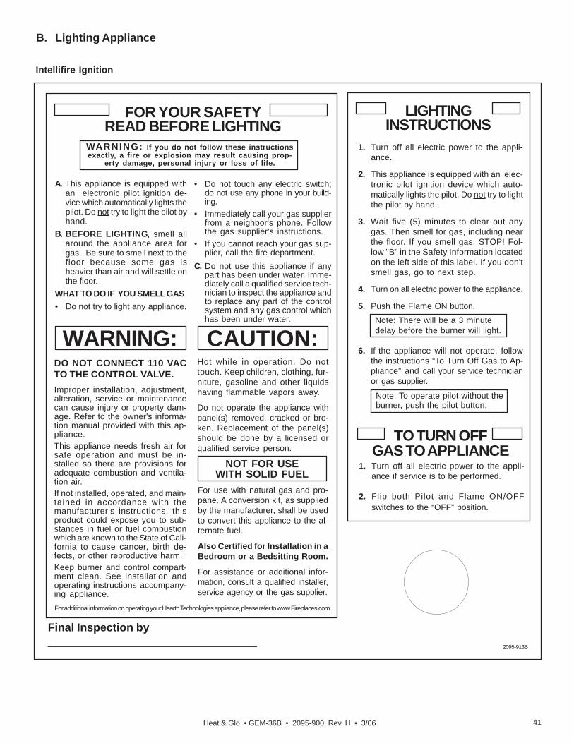
Heat & Glo • GEM-36B • 2095-900 Rev. H • 3/06 41
B. Lighting Appliance
Intellifire Ignition
Final Inspection by_________________________________
LIGHTINGINSTRUCTIONS
TO TURN OFFGAS TO APPLIANCE
1. Turn off all electric power to the appli-ance if service is to be performed.
2. Flip both Pilot and Flame ON/OFFswitches to the “OFF” position.
FOR YOUR SAFETYREAD BEFORE LIGHTING
WARNING: If you do not follow these instructionsexactly, a fire or explosion may result causing prop-
erty damage, personal injury or loss of life.
A. This appliance is equipped withan electronic pilot ignition de-vice which automatically lights thepilot. Do not try to light the pilot byhand.
B. BEFORE LIGHTING, smell allaround the appliance area forgas. Be sure to smell next to thefloor because some gas isheavier than air and will settle onthe floor.
WHAT TO DO IF YOU SMELL GAS• Do not try to light any appliance.
DO NOT CONNECT 110 VACTO THE CONTROL VALVE.Improper installation, adjustment,alteration, service or maintenancecan cause injury or property dam-age. Refer to the owner's informa-tion manual provided with this ap-pliance.This appliance needs fresh air forsafe operation and must be in-stalled so there are provisions foradequate combustion and ventila-tion air.If not installed, operated, and main-tained in accordance with themanufacturer's instructions, thisproduct could expose you to sub-stances in fuel or fuel combustionwhich are known to the State of Cali-fornia to cause cancer, birth de-fects, or other reproductive harm.Keep burner and control compart-ment clean. See installation andoperating instructions accompany-ing appliance.
CAUTION:Hot while in operation. Do nottouch. Keep children, clothing, fur-niture, gasoline and other liquidshaving flammable vapors away.
Do not operate the appliance withpanel(s) removed, cracked or bro-ken. Replacement of the panel(s)should be done by a licensed orqualified service person.
• Do not touch any electric switch;do not use any phone in your build-ing.
• Immediately call your gas supplierfrom a neighbor's phone. Followthe gas supplier's instructions.
• If you cannot reach your gas sup-plier, call the fire department.
C. Do not use this appliance if anypart has been under water. Imme-diately call a qualified service tech-nician to inspect the appliance andto replace any part of the controlsystem and any gas control whichhas been under water.
NOT FOR USEWITH SOLID FUEL
For use with natural gas and pro-pane. A conversion kit, as suppliedby the manufacturer, shall be usedto convert this appliance to the al-ternate fuel.
Also Certified for Installation in aBedroom or a Bedsitting Room.
For assistance or additional infor-mation, consult a qualified installer,service agency or the gas supplier.
WARNING:
2095-913B
For additional information on operating your Hearth Technologies appliance, please refer to www.Fireplaces.com.
1. Turn off all electric power to the appli-ance.
2. This appliance is equipped with an elec-tronic pilot ignition device which auto-matically lights the pilot. Do not try to lightthe pilot by hand.
3. Wait five (5) minutes to clear out anygas. Then smell for gas, including nearthe floor. If you smell gas, STOP! Fol-low "B" in the Safety Information locatedon the left side of this label. If you don'tsmell gas, go to next step.
4. Turn on all electric power to the appliance.
5. Push the Flame ON button.
Note: There will be a 3 minutedelay before the burner will light.
6. If the appliance will not operate, followthe instructions “To Turn Off Gas to Ap-pliance” and call your service technicianor gas supplier.
Note: To operate pilot without theburner, push the pilot button.

Heat & Glo • GEM-36B • 2095-900 Rev. H • 3/0642
C. After Appliance is Lit
D. Frequently Asked Questions
Initial Break-in Procedure
When you light the appliance, you may notice that it pro-duces heat which does have an associated odor or smell.If you feel this odor is excessive it may require the initialthree to four hour continuous burn on high followed by asecond burn up to 12 hours to fully drive off any odor frompaint and lubricants used in the manufacturing process.Condensation of the glass is normal.
NOTE: The appliance should be run three to four hourson the initial start-up. Turn it off and let it cool completely.Remove and clean the glass. Replace the glass and runthe appliance for an additional 12 hours. This will help tocure the products used in the paint and logs.
During this break-in period it is recommended that some win-dows in the house be opened for air circulation. This will helpavoid setting off smoke detectors, and help eliminate anyodors associated with the appliance’s initial burning.
Fire Risk.High Temperatures.
WARNING
Keep combustible household items away from appliance.Do NOT obstruct combustion and ventilation air.• Do NOT place combustible items on top of or in front
of appliance.• Keep furniture, draperies away from appliance.
Smoke and odors released during initial operation.• Open windows for air circulation.• Leave room during initial operation.• Smoke may set off smoke detectors.
Smoke and odors may be irritating to sensitiveindividuals.
CAUTION
• Prevent accidental appliance operation when notattended.
• Unplug or remove batteries from remote control ifabsent or if appliance will not be used for an extendedperiod of time.
• Property damage possible from elevated temperatures.
CAUTION
Fire Hazard.Keep combustible materials, gasolineand other flammable vapors and liquidsclear of appliance.
WARNING
• Do NOT store flammable materials in the appliance’svicinity.
• Do NOT use gasoline, lantern fuel, kerosene, charcoallighter fluid or similar liquids in this appliance.
• Combustible materials may ignite.
ISSUE SOLUTIONS
Condensation on the glass This is a result of gas combustion and temperature variations. As the appliancewarms, this condensation will disappear.
Blue flames This is a result of normal operation and the flames will begin to yellow as theappliance is allowed to burn for 20 to 40 minutes.
Odor from applianceWhen first operated, this appliance may release an odor for the first several hours.This is caused by the curing of the paint and the burning off of any oils remainingfrom manufacturing. Odor may also be released from finishing materials andadhesives used around the appliance.
Film on the glassThis is a normal result of the curing process of the paint and logs. Glass should becleaned within 3 to 4 hours of initial burning to remove deposits left by oils from themanufacturing process. A non-abrasive cleaner such as gas fireplace glass cleanermay be necessary. See your dealer.
Metallic noiseNoise is caused by metal expanding and contracting as it heats up and cools down,similar to the sound produced by a furnace or heating duct. This noise does not affectthe operation or longevity of the appliance.
Is it normal to see the pilot flameburn continually?
In an Intellifire ignition system it is normal to see the pilot flame, but it should turn offwhen ON/OFF is turned off. In a standing pilot system the pilot will always stay on.

Heat & Glo • GEM-36B • 2095-900 Rev. H • 3/06 43
Troubleshooting14With proper installation, operation, and maintenance your gas appliance will provide years of trouble-free service. If you doexperience a problem, this troubleshooting guide will assist a qualified service person in the diagnosis of a problem and thecorrective action to be taken. This troubleshooting guide can only be used by a qualified service technician.
A. Intellifire Ignition SystemSymptom Possible Causes Corrective Actions
1. Theignitor/modulemakes noise, but nospark.
a. Incorrect wiring. Verify "S" wire (white) for sensor and "I" wire (orange) for ignitor areconnected to correct terminals on module and pilot assembly. Reversed wiresat the module may cause system to make sparking noise, but spark may notbe present at pilot hood.
b. Looseconnections orelectrical shorts inthe wiring.
Verify no loose connections or electrical shorts in wiring from module to pilotassembly. Rod closest to pilot hood should be ignitor. Verify connectionsunderneath pilot assembly are tight; also verify connections are not groundingout to metal chassis, pilot burner, pilot enclosure, mesh screen if present, orany other metal object.
c. Ignitor gap is toolarge.
Verify gap of igniter to pilot hood. The gap should be approximately .17 inchor 1/8 inch.
d. Faulty module. Turn ON/OFF rocker switch or wall switch to OFF position. Remove ignitorwire "I" from module. Place ON/OFF Rocker switch or wall switch in ONposition. Hold ground wire about 3/16 inch away from "I" terminal on module.If there is no spark at "I" terminal module must be replaced. If there is a sparkat "I" terminal, module is fine. Inspect pilot assembly for shorted sparker wireor cracked insulator around electrode.
2. Pilot won't light,there is no noise orspark.
a. A shorted orloose connection inwiring configurationor wiring harness.
Remove and reinstall the wiring harness that plugs into module. Verify there isa tight fit. Verify pilot assembly wiring to module. Remove and verify continuityof each wire in wiring harness.
b. Improper wallswitch wiring.
Verify that 110/VAC power is "ON" to junction box.
c. Module notgrounded.
Verify black ground wire from module wire harness is grounded to metalchassis of appliance.
d. Faulty module. Turn ON/OFF rocker switch or wall switch to OFF position. Remove ignitorwire "I" from module. Place ON/OFF Rocker switch or wall switch in ONposition. Hold ground wire about 3/16 inch away from "I" terminal on module.If there is no spark at "I" terminal module must be replaced. If there is a sparkat "I" terminal, module is fine. Inspect pilot assembly for shorted sparker wireor cracked insulator around electrode.
3. Pilot lights butcontinues to spark,and main burner willnot ignite. (If thepilot continues tospark after the pilotflame has been lit,flame rectificationhas not occurred.)
a. A shorted orloose connection insensor rod.
Verify all connections to wiring diagram in manual. Verify connectionsunderneath pilot assembly are tight. Verify connections are not grounding outto metal chassis, pilot burner, pilot enclosure or screen if present, or any othermetal object.
b. Poor flamerectification orcontaminatedsensor rod.
Verify that flame is engulfing sensor rod. If the pilot assembly does not have aground strap, consider installing one to increase flame rectification. Verifycorrect pilot orifice is installed and inlet gas specifications. Flame carriesrectification current, not the gas. If flame lifts from pilot hood, the circuit isbroken. A wrong orifice or too high an inlet pressure can cause pilot flame tolift. The sensor rod may be contaminated. Clean sensor rod with emery cloth.
c. Module is notgrounded.
Verify that module is securely grounded to metal chassis of appliance. Verifythat wire harness is firmly connected to module.

Heat & Glo • GEM-36B • 2095-900 Rev. H • 3/0644
Troubleshooting (continued)
Intellifire Ignition System
Symptom Possible Causes Corrective Actions3. (Continued) d. Damaged pilot
assembly or dirtysensor rod.
Verify that ceramic insulator around the sensor rod is not cracked, damaged,or loose. Verify connection from sensor rod to white sensor wire. Cleansensor rod with emery cloth to remove any contaminants that may haveaccumulated on sensor rod. Verify continuity with a multimeter with ohms setat lowest range.
e. Faulty module. Turn ON/OFF rocker switch or wall switch to OFF position. Remove ignitorwire "I" from module. Place ON/OFF Rocker switch or wall switch in ONposition. Hold ground wire about 3/16 inch away from "I" terminal on module.If there is no spark at "I" terminal module must be replaced. If there is a sparkat "I" terminal, module is fine. Inspect pilot assembly for shorted sparker wireor cracked insulator around electrode.
4. Pilot sparks, butPilot will not light.
a. Correct gassupply.
Verify that incoming gas line ball valve is "open". Verify that inlet pressurereading is within acceptable limits, inlet pressure must not exceed 14 in. W.C.
b. Ignitor gap is toolarge.
Verify that spark gap from ignitor to pilot hood is .17 in. or 1/8 in.
c. Module is notgrounded.
Verify module is securely grounded to metal chassis of appliance.
d. Module voltageoutput / Valve/Pilotsolenoid ohmsreadings.
Verify battery voltage is at least 2.7 volts. Replace batteries if voltage isbelow 2.7.

Heat & Glo • GEM-36B • 2095-900 Rev. H • 3/06 45
Maintaining and Servicing Appliance15Although the frequency of appliance servicing and maintenance will depend on use and the type of installation, a qualified servicetechnician should perform an appliance checkup at the beginning of each heating season.
WARNINGAnnual inspection by qualified technician recommended.
Check:• Condition of doors, surrounds and fronts.• Condition of glass, glass assembly and glass seal.• Obstructions of combustion and ventilation air.• Condition of logs.• Condition of firebox.• Burner ignition and operation.• Burner air shutter adjustment• Gas connections and fittings.• Obstructions of termination cap.Clean:• Glass• Air passageways, grilles,
control compartment• Burner, burner portsRisk of:• Fire• Delayed ignition or explosion• Exposure to combustion fumes• Odors
Handle glass assembly with care.
NOTE: Clean glass after initial 3-4 hoursoperation. Longer operation withoutcleaning glass may cause a permanentwhite film on glass.
CAUTION
When cleaning glass door:• Avoid striking, scratching or slamming glass.• Do NOT use abrasive cleaners.• Use a hard water deposit glass cleaner on white film.• Do NOT clean glass when hot.• Turn off appliance after 3-4 hours of operation and
ALLOW TO COOL.• Remove and clean glass assembly.• Replace glass assembly and operate appliance for
additional 12 hours.Refer to maintenance instructions.
Risk of injury or property damage.Before servicing:• Turn off gas.• Turn off electricity to appliance.• Disable remote control, if one is present.• Ensure appliance is completely cooled.After servicing:• Replace any screen or barrier that was removed.• Reseal and reinstall any venting removed for servicing.
WARNING
Inspect external vent cap regularly.• Ensure no debris blocks cap.
WARNING
• Combustible materials blocking cap may ignite.• Restricted air flow affects burner operation.

Heat & Glo • GEM-36B • 2095-900 Rev. H • 3/0646
Inspect Maintenance TasksDoors, Surroundsand Fronts
1. Assess condition of screen and replace as necessary. Recommend addition of screenif one is not present.2. Inspect for scratches, dents or other damage and repair as necessary.
3. Verify no obstructions to airflow through the louvers.
4. Verify maintenance of proper clearance to combustible household objects.
Gasket Seal, GlassAssembly and Glass 1. Inspect gasket seal and its condition.
2. Inspect glass panels for scratches and nicks that can lead to breakage when exposed toheat.3. Confirm there is no damage to glass or glass frame. Replace as necessary.
4. Verify that latches engage properly, clip studs are not stripped, and glass attachmentcomponents are intact and operating properly. Replace as necessary.5. Clean glass. Replace glass assembly if severely coated with silicate deposits that cannotbe removed.
Valve Compartmentand Firebox Top
1. Vacuum and wipe out dust, cobwebs, debris or pet hair. Use caution when cleaning theseareas. Screw tips that have penetrated the sheet metal are sharp and should be avoided.2. Remove any foreign objects.
3. Verify unobstructed air circulation.
Logs 1. Inspect for broken, damaged, or missing logs. Replace as necessary.2. Verify correct log placement and no flame impingement causing sooting. Correct asnecessary.
Firebox 1. Inspect for paint condition, warpage, corrosion or perforation. Sand and repaint asnecessary.
2. Replace appliance if firebox has been perforated.
Burner Ignition andOperation 1. Verify burner is properly secured and aligned with pilot or igniter.
2. Clean off burner top, inspect for plugged ports, corrosion or deterioration. Replace burner ifnecessary.3. Replace ember materials with new dime-size and shape pieces. Do not block ports orobstruct lighting paths.
4. Check for smooth lighting and ignition carryover to all ports. Verify there is no ignition delay.
5. Inspect for lifting or other flame problems.
6. Verify air shutter is clear of dust and debris.
7. Inspect orifice for soot, dirt or corrosion.
8. Verify manifold and inlet pressures. Adjust regulator as required.
9. Inspect pilot flame strength. Clean or replace orifice as necessary.
10. Inspect thermocouple/thermopile or IPI sensor rod for soot, corrosion and deterioration.Clean with emery cloth or replace as required.11. Verify millivolt output. Replace as necessary.
Venting 1. Inspect venting for blockage or obstruction such as bird nests, leaves, etc.
2. Confirm that termination cap remains clear and unobstructed by plants, etc.3. Verify that termination cap clearance to subsequent construction (building additions, decks,fences or sheds) has been maintained.4. Inspect for corrosion or separation.5. Verify weather stripping, sealing and flashing remains intact.
6. Inspect draft shield to verify it is not bent, damaged or missing.
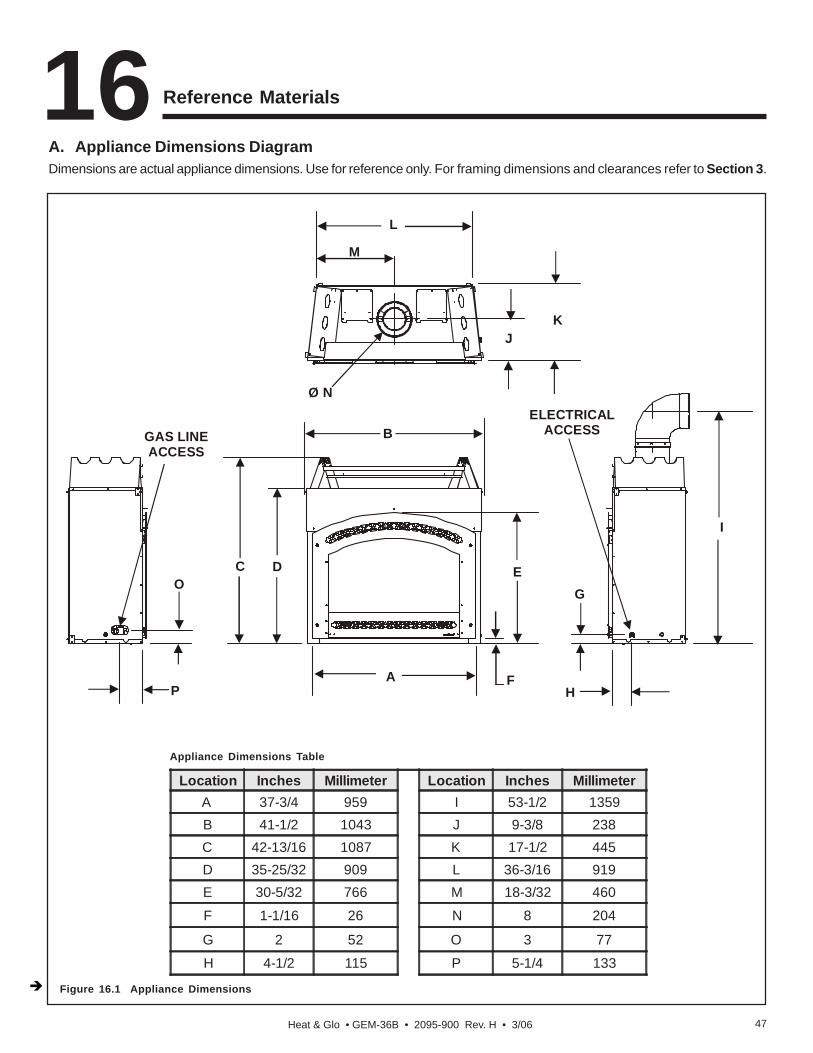
Heat & Glo • GEM-36B • 2095-900 Rev. H • 3/06 47
Reference Materials16
Location Inches Millimeter Location Inches MillimeterA 37-3/4 959 I 53-1/2 1359B 41-1/2 1043 J 9-3/8 238C 42-13/16 1087 K 17-1/2 445D 35-25/32 909 L 36-3/16 919E 30-5/32 766 M 18-3/32 460
F 1-1/16 26 N 8 204
G 2 52 O 3 77
H 4-1/2 115 P 5-1/4 133
Appliance Dimensions Table
A. Appliance Dimensions DiagramDimensions are actual appliance dimensions. Use for reference only. For framing dimensions and clearances refer to Section 3.
Figure 16.1 Appliance Dimensions
L
M
Ø N
KJ
GAS LINEACCESS
O
P
C D
A
B
E
F
ELECTRICALACCESS
G
H
I
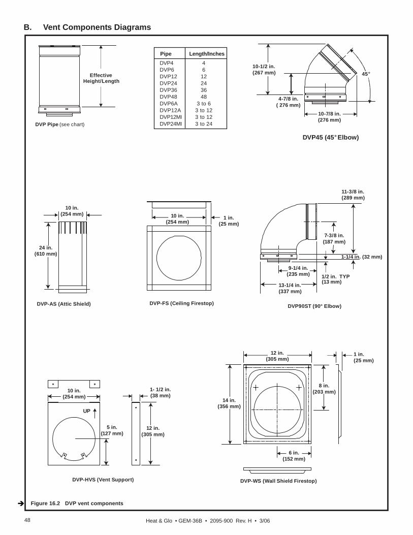
Heat & Glo • GEM-36B • 2095-900 Rev. H • 3/0648
B. Vent Components Diagrams
Figure 16.2 DVP vent components
Pipe Length/InchesDVP4 4DVP6 6DVP12 12DVP24 24DVP36 36DVP48 48DVP6A 3 to 6DVP12A 3 to 12DVP12MI 3 to 12DVP24MI 3 to 24
10-1/2 in.(267 mm)
10-7/8 in.(276 mm)
45°
7-3/8 in.(187 mm)
11-3/8 in.(289 mm)
1-1/4 in. (32 mm)
9-1/4 in.(235 mm)
13-1/4 in.(337 mm)
1/2 in. TYP
DVP90ST (90° Elbow)
10 in.(254 mm)
1 in.(25 mm)
12 in.(305 mm)
14 in.(356 mm)
1 in.(25 mm)
8 in.(203 mm)
6 in.(152 mm)
10 in.(254 mm)
1- 1/2 in.(38 mm)
5 in.(127 mm)
12 in.(305 mm)
UP
10 in.(254 mm)
24 in.(610 mm)
DVP-HVS (Vent Support)
DVP-AS (Attic Shield)
DVP-WS (Wall Shield Firestop)
DVP-FS (Ceiling Firestop)
°DVP45 (45 Elbow)
DVP Pipe (see chart)
EffectiveHeight/Length
4-7/8 in.( 276 mm)
(13 mm)

Heat & Glo • GEM-36B • 2095-900 Rev. H • 3/06 49
B. Vent Components Diagrams (continued)
Figure 16.3 DVP vent components
(Shown with optional extended heat shield)
DVP-TRAP SERIESHorizontal Term Cap
15-1/8 in.(384 mm)
14 in.(566 mm)
8 in.(203 mm)
MaxEffectiveLength
DVP-TRAP1
DVP-Trap2 DVP-TRAPK1
DVP-TRAPK2
Minimum MaximumTerm Cap Effective Effective
TRAP1 4-1/8 in. 5-5/8 in.TRAP2 6-3/4 in. 10-5/8 in.
LengthLength
7-1/4 in.(184 mm)
5-1/4 in.(133 mm)
12-1/2 in.(318 mm)
DVP-TVHWVertical Termination Cap (High wind)

Heat & Glo • GEM-36B • 2095-900 Rev. H • 3/0650
B. Vent Components Diagrams (continued)
Figure 16. 4 DVP vent components
13-1/4 in.(367 mm)
24-5/8 in.(625 mm)
27-1/2 in.(127 mm)
RF6MRoof Flashing Multi-pak
31 in.(787 mm)
24-5/8 in.(625 mm)
13-1/4 in.(367 mm)
RF12MRoof Flashing Multi-pak
DVP-BEK2Trap Cap Brick Extension
13-7/8 in.(352 mm)
5 in.(127 mm)
11-7/8 in.(302 mm)
BEKTrap Cap Brick Extension
13-3/4 in.(349 mm)
5 in.(127 mm)13-3/4 in.
(349 mm)
DVP-TRAPFLFlashing DRC-RADIUS
Cap Shield
13-7/8 in.(352 mm)
9-1/2 in.(241 mm)
14 in.(356 mm)
COOL-ADDCap Shield
11-5/8 in.(295 mm)
5-3/4 in.(146 mm)
7-1/8 in.(181 mm)
12-1/8 in.(308 mm)

Heat & Glo • GEM-36B • 2095-900 Rev. H • 3/0654
© 2005 Hearth & Home Technologies Inc.
LIMITED LIFETIME WARRANTYHEAT & GLO GAS APPLIANCE PRODUCTS
BASIC ONE-YEAR WARRANTY. HEAT & GLO, a brand of HEARTH & HOME TECHNOLOGIES INC., located at 20802 KensingtonBoulevard, Lakeville, MN 55044, (“HEAT & GLO”) warrants to the original owner that your new HEAT & GLO Gas Appliance (the “Product”)will be free from defects in materials and workmanship for a period of one year from the date of installation. During the first year, HEAT & GLOwill replace or repair, at its discretion, any defective components at its sole cost and expense, including payment of all reasonable labor costsincurred in replacing or repairing such components. This basic warranty is subject to the conditions, exclusions and limitations described below.EXTENDED LIFETIME COVERAGE. HEAT & GLO warrants that the firebox, heat exchanger, log(s), and burner will not be defective inmaterial or workmanship during the period the Product is owned by the original owner, subject to the following conditions, exclusions andlimitations described below.CONDITIONS, EXCLUSIONS AND LIMITATIONS:1. This warranty applies to the original owner only and is nontransferable.2. This warranty applies only to Products installed in the United States of America or Canada.3. This warranty is limited to the replacement or repair of defective components or workmanship and HEAT & GLO may fully discharge all
obligations under this warranty by repairing or replacing, at its discretion, the defective components. The maximum amount recoverableunder this warranty is limited to the purchase price of the Product and, if HEAT & GLO is unable to provide replacement or repair in anexpedient and cost-effective manner, HEAT & GLO may discharge all obligations under this warranty by refunding the purchase price ofthe Product. IN NO EVENT SHALL HEAT & GLO BE LIABLE FOR ANY INCIDENTAL OR CONSEQUENTIAL DAMAGES CAUSED BYDEFECTS IN THE PRODUCT.
4. Any labor and related repair charges relating to the costs and expenses of replacing or repairing defective components under the LimitedLifetime Warranty are not covered by this warranty, except as provided for under the Basic One-Year Warranty.
5. Components and parts made by other manufacturers, whether sold with the Product or added thereafter, are NOT covered by thiswarranty unless expressly authorized and approved by HEAT & GLO in writing.
6. Any damages caused by environmental conditions, inadequate ventilation or drafting caused by tight sealing construction of the structure,air handling devices such as exhaust fans or forced air furnaces, or other such causes are not covered by this warranty.
7. This warranty will be void if:a) The Product is not installed, operated and maintained in compliance with local building codes and with the instructions in the Installer’s
Guide, Owner’s Guide and Listing Agent Identification Label furnished with the Product.b) Any parts or components made by other manufacturers are added or used in the Product, unless expressly authorized and
approved by HEAT & GLO in writing.c) Any service work is performed on the Product by anyone other than an authorized HEAT & GLO representative.d) The Product is damaged due to shipping, improper handling, accident, abuse or misuse.e) Fuels other than those specified in the Installer’s Guide and Owner’s Guide are used.f ) Modification was made to the Product which was not expressly authorized and approved by HEAT & GLO in writing.
EXCEPT TO THE EXTENT PROVIDED BY LAW, HEAT & GLO MAKES NO EXPRESS WARRANTIES OTHER THAN THE WARRANTYSPECIFIED HEREIN. THE DURATION OF ANY IMPLIED WARRANTY IS LIMITED TO THE DURATION OF THE WARRANTY SPEC-IFIED ABOVE.Some states do not allow limitations on how long an implied warranty lasts, or do not allow exclusion or limitation of incidental or consequentialdamages, so those limitations may not apply to you. This warranty gives you specific legal rights, and you may also have other rights which varyfrom State to State.If warranty service is needed you should contact your installing dealer and if the installing dealer is unable to provide necessary parts orcomponents, contact the nearest authorized HEAT & GLO dealer or supplier.NOTES TO CUSTOMER:1. In order to insure proper installation, operation and maintenance HEAT & GLO strongly recommends annual
servicing by an authorized HEAT & GLO dealer.2. Please complete this information and retain this warranty in a safe place for future reference: Installation Date:______
Model #:_________________ Serial #:______________ Installing Contractor:_________________________3. HEAT & GLO reserves the right to make changes at any time, without notice, in design, material, specifications
and prices of the Product. HEAT & GLO also reserves the right to discontinue styles and products.
060-981D 3/05
D. Limited Lifetime Warranty
Heat & Glo • GEM-36B • 2095-900 Rev. H • 3/06 55
Heat & Glo, a brand of Hearth & Home Technologies Inc.20802 Kensington Boulevard, Lakeville, MN 55044
www.fireplaces.com
E. Contact Information
Please contact your Heat & Glo dealer with any questions or concerns.For the number of your nearest Heat & Glo dealer,
please call 1-888-427-3973.
- NOTES -
_______________________________________________________________________________
_______________________________________________________________________________
_______________________________________________________________________________
_______________________________________________________________________________
_______________________________________________________________________________
_______________________________________________________________________________
_______________________________________________________________________________
_______________________________________________________________________________
_______________________________________________________________________________
Printed in U.S.A. - Copyright 2006
DO NOT DISCARD THIS MANUAL
CAUTION
Important operating andmaintenance instruc-tions included.
Read, understand andfollow these instructionsfor safe installation andoperation.
Leave this manual withparty responsible for useand operation.
• • •
This product may be covered by one or more of the following patents: (United States) 4593510, 4686807, 4766876, 4793322, 4811534, 5000162, 5016609, 5076254, 5113843, 5191877, 5218953, 5263471, 5328356, 5341794,5347983, 5429495, 5452708, 5542407, 5601073, 5613487, 5647340, 5688568, 5762062, 5775408, 5890485, 5931661, 5941237, 5947112, 5996575, 6006743, 6019099, 6048195, 6053165, 6145502, 6170481, 6237588, 6296474,6374822, 6413079, 6439226, 6484712, 6543698, 6550687, 6601579, 6672860, 6688302B2, 6715724B2, 6729551, 6736133, 6748940, 6748942, 6769426, 6774802, 6796302, 6840261, 6848441, 6863064, 6866205, 6869278,6875012, 6880275, 6908039, 6919884, D320652, D445174, D462436; (Canada) 1297749, 2195264, 2225408, 2313972; (Australia) 780250, 780403, 1418504 or other U.S. and foreign patents pending.