owner's manual digital recording systems - blicon · digital recording systems ... - access...
TRANSCRIPT

GRH-K1004A.34.1.01.12.2011
Owner's Manual
© ASP AG
Digital Recording Systems
GRH-K1004A 4 Channel H.264 HD-SDI Recorder with DVD-RW Drive
GRH-K2108A 8 Channel H.264 HD-SDI Recorder with DVD-RW Drive


Content:
1. Introduction 1
1. Available Versions 2
2. Key Features of your DVR 2
2. Important Safety Instructions 3
3. Package Contents 4
4. Installation 5
1. Part Names and Functions 5
2. Installation and Connection 8
3. Running the OSD menu 10
4. Connecting and Configuring Ports 18
5. Menu Use 30
1. Menu Structure 30
2. Function Menu 30
3. Factory Reset 31
6. Monitoring 36
1. Basic Screen 36
2. Single Full Screen Mode 36
3. Multi Screen Mode 36
4. Screen Description 36
5. Sequence Mode 37
6. Event Screen 37
7. Zoom Screen Mode 38
8. Pause Live Screen 38
9. PTZ Control 39
7. Playback 41
1. Playback Mode 41
2. Search Mode 42
3. Copy 45
8. Configuration 49
1. System Setup 49
2. Network 60
3. Device Setup 63
4. Event Setup 68
5. Recording Setup 75
9. GRUNDIG Web Viewer 79
1. System Requirements 79
2. Login 79
3. User Setup 80
4. Available Browser 81
5. Monitor 81
6. Playback 86
7. Java based Web Viewer 90
10. GRUNDIG Live Mobile Viewer 91
1. Log-In Page 91
2. Monitoring Page 92
1. Introduction
Thank you for purchasing a GRUNDIG digital video recorder for HD-SDI signals. This manual is for GRH-K2108A
and GRH-K1004A.
Based on the Television Standard for FullHD Television, HDcctv products feature up to 2 Megapixel (1920x1080)
pictures in real-time (30fps) transmitted over coax cabling.
Get the advantages of IP technology without their drawbacks: 16:9 megapixel pictures without network
configuration, bandwidth problems and network security risks. Use existing coax cables and only exchange the
cameras and recorders. Get a “real” live picture and see the things that happen in the now, not a few seconds
ago. Connect a monitor directly to a camera using only a HDcctv-to-HDMI converter.
HDcctv is easy to handle, easy to install and produces amazing high quality pictures.
Before product installation and operation, please become thoroughly familiar with this user manual and other
manuals referenced by this manual.
This user manual, the software and the hardware described here are protected by copyright law. With the
exception of copying for general use within fair use, copying and reprinting the user manual, either partially or in
entirety, or translating it into another language without the consent of ASP AG is strictly prohibited.
This specification may change without prior notice for improvement of product performance.
1English
Product Warranty and Limits of Responsibility
The manufacturer does not assume any responsibility concerning the sale of this product and does not delegate
any right to any third party to take any responsibility on its behalf. No warranty is offered for any attachments or
parts not supplied by the manufacturer. The product warranty does not cover cases of accidents, negligence,
alteration, misuse or abuse, for example:
- Malfunctions due to negligence by the user
- Deliberate disassembly and replacement by the user
- Connection of a power source other than a properly rated power source
- Malfunctions caused by natural disasters (fire, flood, tidal wave, etc.)
- Replacement of expendable parts (HDD, FAN, etc.)
- The warranty period for the HDD and Fan is one year after purchase.
This product is not for exclusive use of crime prevention but also for assistance in cases of fire. We take no
responsibility for damage from any incident.
Caution:
This equipment underwent EMC registration and is suitable for business purposes. Distributors and users are
aware of this point.
Warning:
This is a class A product. In a domestic environment this product may cause radio interference, in which case the
user may be required to take adequate measures.
Warning:
1. In case of changing the built-in lithium battery, it should be replaced with the same or a kindred one to prevent
danger of explosion. Since old batteries could be a factor of environment contamination, be cautious how you
treat them.
2. Do not throw the batteries into fire or other heat. Short circuit or disassembly is prohibited.
3. Do not charge the batteries provided with the remote control.
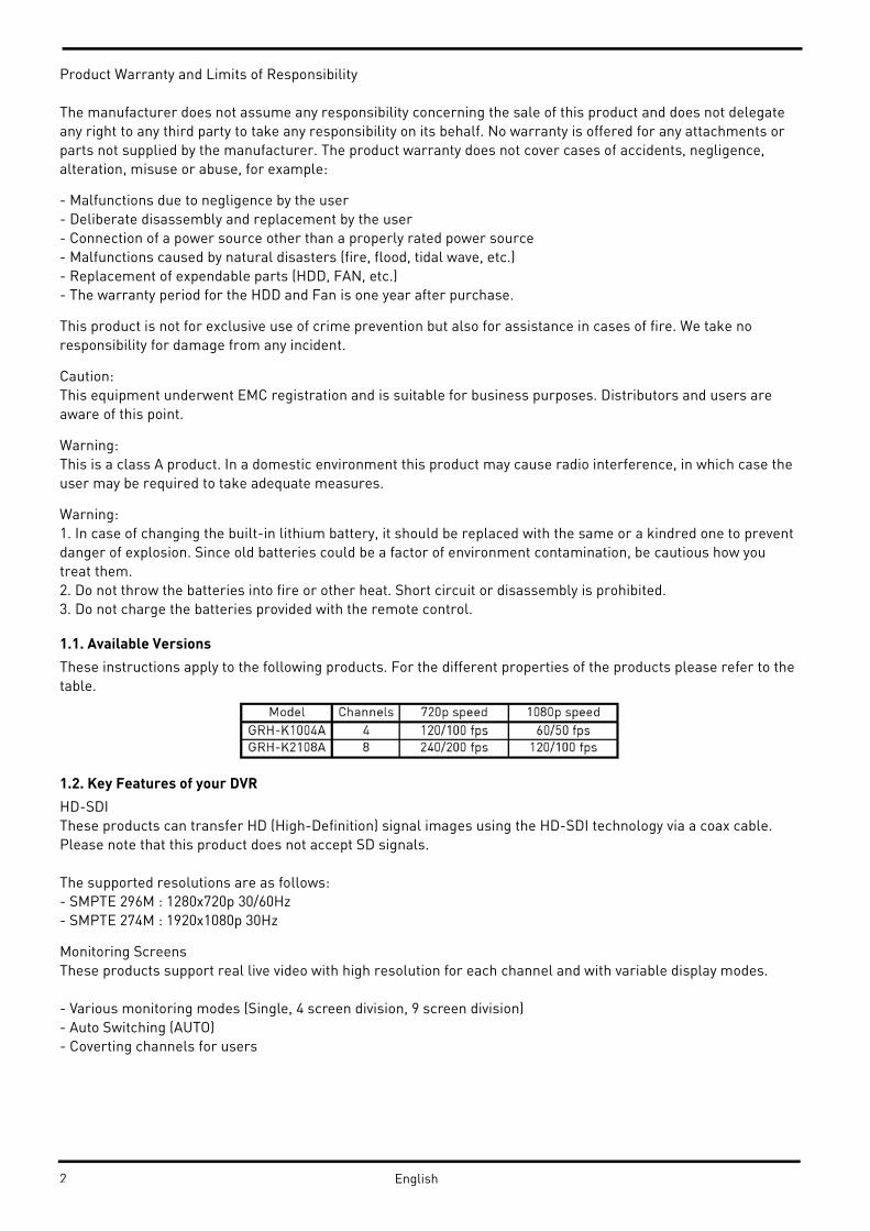
1.1. Available Versions
These instructions apply to the following products. For the different properties of the products please refer to the
table.
1.2. Key Features of your DVR
HD-SDI
These products can transfer HD (High-Definition) signal images using the HD-SDI technology via a coax cable.
Please note that this product does not accept SD signals.
The supported resolutions are as follows:
- SMPTE 296M : 1280x720p 30/60Hz
- SMPTE 274M : 1920x1080p 30Hz
Monitoring Screens
These products support real live video with high resolution for each channel and with variable display modes.
- Various monitoring modes (Single, 4 screen division, 9 screen division)
- Auto Switching (AUTO)
- Coverting channels for users
2 English
Audio Recording
These products support real-time audio input and recording.
- Simultaneous 4ch audio input & recording available
- Input : 4ch RCA, Output : 1ch(Rear)
- Simultaneous audio recording and playback available
Recording
These products support max. 120fps (GRH-K1004A) or 240fps (GRH-R2108A) recording in high-quality HD-SDI
video and it is possible to record max. 5 seconds before an event is triggered.
- HD-SDI video recording
GRH-K2108A : 1920 x 1080 (1080P) : 60ips
GRH-K2108A : 1920 x 1080 (1080P) : 120ips
GRH-K2108A : 1280 x 720 (720P) : 120ips
GRH-K2108A : 1280 x 720 (720P) : 240ips
- Supports manual, continuous, schedule & event recording
- Video loss detection
- Supports archiving an event list (Sensor, Video loss, Motion detection, Text)
Search / Playback
These products support variable and convenient functions for search & playback.
- Search for Events (Motion, Video Loss, Text & Relays)
- Search for Dates (Calendar & Date input method)
- Smart Search for Motion Detection
- All Search methods can be used via DVR, remote control & USB mouse
Backup devices
You can back up to DVD-R, CD-R & USB (Fat32 formatted)
- Supports various backup devices : DVD-R, CD-R, USB
- eSATA port for external recording HDDs
Network
These products support networks like LAN, XDSL and can be easily controlled from remote site using the
GRUNDIG Control Center Software.
- E-mail and or Twitter notification
- Access Live and playback with many Web browsers. Backup with the Internet Explorer
- Access Live, playback, search, backup and DVR management with the GRUNDIG Control Center Software
- Record, search & playback over a network
- 10/100Mbps Ethernet/xDSL connection
ETC
- User friendly GUI with mouse function
- Easy and simple firmware upgrade over USB or the network
- PTZ Control (several protocols), PRESET function
- Control of up to 16 DVRs with one remote controller
- 10/100/1000Mbps connection for the external storage device GDS-R04A
- Advanced user management with coverting function
2. Important Safety Instructions
1. Do not place heavy objects on the top of the product.
3English

2. This Product is for indoor use. It is not weatherproof. Please use the product considering its environmental
specifications (Temperature & Humidity). To clean the product, gently wipe the outside with a clean dry cloth.
3. This Product uses AC power of 110V ~ 240V. Be cautious not to cause electric damages to the product.
4. Be careful not to drop the product. Physical shocks may harm the product including the internal HDD. In
addition, be sure the product is secured after installation.
5. This Product is made of metal. Therefore you can hurt human beings if you throw it to them or hit it on them.
When installing the product, be cautious to locate it in safe places where children cannot reach it.
6. If the product does not operate properly, please contact the closest GRUNDIG distributor for after sales
service. Tampering or disassembling the product will cause expiration of the warranty.
7. Security surveillance laws may differ for each country. Therefore, please contact the local region first to avoid
any surveillance law violations.
8. Experience and technical skills are needed for the installation of this product as an improper installation may
cause fire, electric shocks, or defects. Any installation job should be performed by the vendor you purchased this
product from.
The content of this manual can differ according to firmware or software upgrading. The standard and appearance
of the products may be changed for the improvement of quality without an advance notice.
3. Package Contents
These parts are included:
4 English

4. Installation
4.1. Part Names and Functions
Front view of GRH-K1004A & GRH-K2108A:
5 English

Rear view of GRH-K2108A & GRH-K2108A:
6English
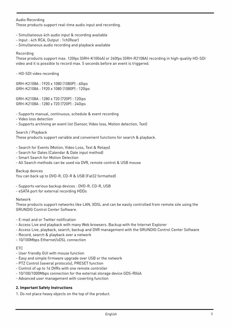
Remote Control:
It is possible to use all functions of the DVR with the remote control,. If several DVRs are set with unique ID
numbers, they can be controlled with one remote control. To use the remote control, it is necessary to set first
the ID which you want to use. Keep pressing the ID button repeatedly (up to max. 16 times) and use it for
matching DVR & ID.
7 English
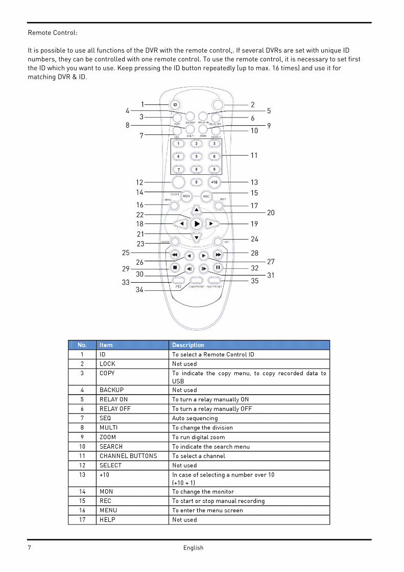
4.2. Installation and Connection
Connecting the camera:
Connect the CCTV camera to the DVR using the BNC cable as shown below:
Please make sure that all connected cameras fulfil the SMPTE standards 296M or 274M, or a compatible one. The
DVR will recognise the camera automatically. If you do not get a video, please check the connections first and
then make sure the distance is not too far for HDcctv signal:
RG59 cable: ca. 100-120m
RG6 cable: ca. 200m
For bigger distances, please use the GTH-L0011E extender from GRUNDIG.
8English
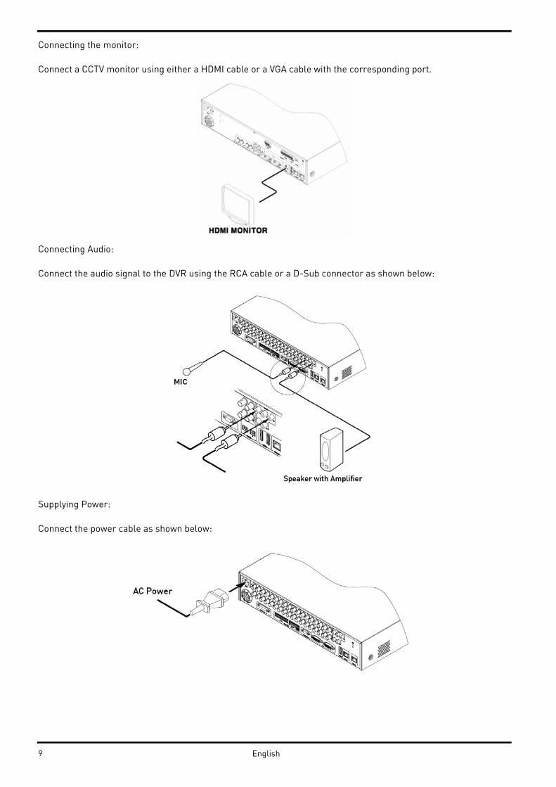
Connecting the monitor:
Connect a CCTV monitor using either a HDMI cable or a VGA cable with the corresponding port.
Connecting Audio:
Connect the audio signal to the DVR using the RCA cable or a D-Sub connector as shown below:
Supplying Power:
Connect the power cable as shown below:
9 English

- When supplying the DVR with power, the DVR starts booting automatically.
- In order to cut off the power, press the power switch on the DVR front for 5 seconds. When a pop-up window
appears, select “YES” to shut down the DVR.
- For supplying the DVR with power again, push the Power button.
4.3. Running the OSD menu
The OSD can be controlled with the keypad on the front panel of the DVR, with a remote control or with an USB
mouse. In this manual we will refer to the keys of the front panel, as the procedure with a remote control and a
mouse is almost identical.
4.3.1. OSD Menu Configuration
Press [MENU] on the keypad on the front to open the configuration menu as shown below:
(1) Main Menu : The selected tab is shown in bright colour and the related sub-menu will be shown on the left,
below the tab. To move to the previous/next tab, use the [◀/▶] arrow buttons. To move to a sub-menu, press the
[Enter] key.
(2) Submenu : The selected sub-menu is shown as a tab title and the related setting will be shown. To move to the
previous/next tab, use the [◀/▶,▲/▼] arrow buttons. To move to the related setting, press [Enter]. To move to an
upper main menu, press the [ESC] button.
(3) Setting page : The selected tab is shown in blue. To move to the previous/next tab, use the [◀/▶] or [▲/▼]
arrow button and press the [Enter] key for value setting. When setting the value is a word, a dialogue box to edit
the word will open. When setting the value is a number, it should be set with using [◀/▶] or [▲/▼]. Press the
[ESC] button when the value is set. With the [ESC] button it is also possible to move to the upper sub-menu.
10English
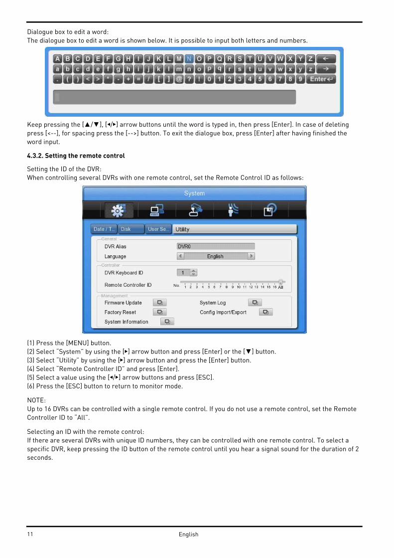
Dialogue box to edit a word:
The dialogue box to edit a word is shown below. It is possible to input both letters and numbers.
Keep pressing the [▲/▼], [◀/▶] arrow buttons until the word is typed in, then press [Enter]. In case of deleting
press [<--], for spacing press the [-->] button. To exit the dialogue box, press [Enter] after having finished the
word input.
4.3.2. Setting the remote control
Setting the ID of the DVR:
When controlling several DVRs with one remote control, set the Remote Control ID as follows:
(1) Press the [MENU] button.
(2) Select “System” by using the [▶] arrow button and press [Enter] or the [▼] button.
(3) Select “Utility” by using the [▶] arrow button and press the [Enter] button.
(4) Select “Remote Controller ID” and press [Enter].
(5) Select a value using the [◀/▶] arrow buttons and press [ESC].
(6) Press the [ESC] button to return to monitor mode.
NOTE:
Up to 16 DVRs can be controlled with a single remote control. If you do not use a remote control, set the Remote
Controller ID to “All”.
Selecting an ID with the remote control:
If there are several DVRs with unique ID numbers, they can be controlled with one remote control. To select a
specific DVR, keep pressing the ID button of the remote control until you hear a signal sound for the duration of 2
seconds.
11 English

Operable range of the remote control:
Loading the batteries into the remote control:
The remote control requires two AAA-type batteries. Please refer to the following installation steps.
4.3.3. Different configurations
Basic configuration:
12English

Advanced configuration:
13 English

Connection to an USB storage device for backups:
Internet/Intranet configuration:
4.3.4. Basic Settings
Viewing Image:
When powered on, the DVR starts automatically and displays a basic 4 ch-split (GRH-K1004A) or 8-split screen
(GRH-K2108A).
NOTE:
After booting the recorder, by default a prompt for entering the password will appear. The default admin
password is: 1234.
14English
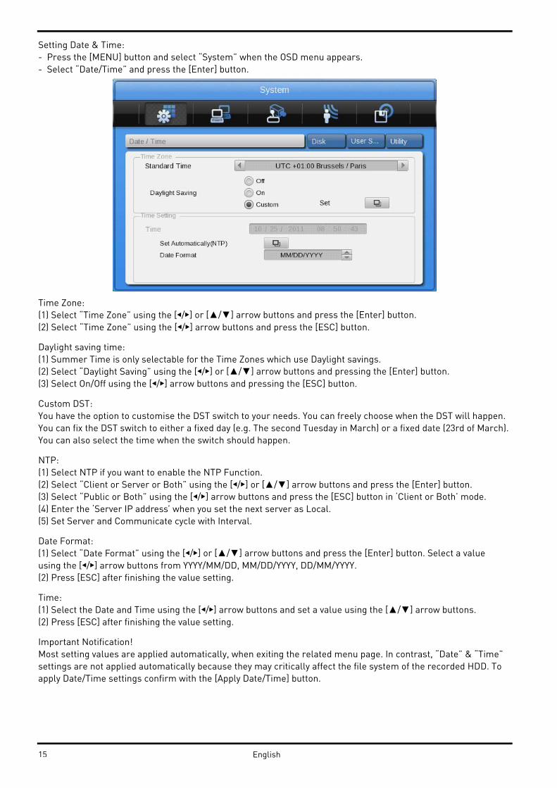
Setting Date & Time:
- Press the [MENU] button and select “System” when the OSD menu appears.
- Select “Date/Time” and press the [Enter] button.
Time Zone:
(1) Select “Time Zone” using the [◀/▶] or [▲/▼] arrow buttons and press the [Enter] button.
(2) Select “Time Zone” using the [◀/▶] arrow buttons and press the [ESC] button.
Daylight saving time:
(1) Summer Time is only selectable for the Time Zones which use Daylight savings.
(2) Select “Daylight Saving” using the [◀/▶] or [▲/▼] arrow buttons and pressing the [Enter] button.
(3) Select On/Off using the [◀/▶] arrow buttons and pressing the [ESC] button.
Custom DST:
You have the option to customise the DST switch to your needs. You can freely choose when the DST will happen.
You can fix the DST switch to either a fixed day (e.g. The second Tuesday in March) or a fixed date (23rd of March).
You can also select the time when the switch should happen.
NTP:
(1) Select NTP if you want to enable the NTP Function.
(2) Select “Client or Server or Both” using the [◀/▶] or [▲/▼] arrow buttons and press the [Enter] button.
(3) Select “Public or Both” using the [◀/▶] arrow buttons and press the [ESC] button in ‘Client or Both’ mode.
(4) Enter the ‘Server IP address’ when you set the next server as Local.
(5) Set Server and Communicate cycle with Interval.
Date Format:
(1) Select “Date Format” using the [◀/▶] or [▲/▼] arrow buttons and press the [Enter] button. Select a value
using the [◀/▶] arrow buttons from YYYY/MM/DD, MM/DD/YYYY, DD/MM/YYYY.
(2) Press [ESC] after finishing the value setting.
Time:
(1) Select the Date and Time using the [◀/▶] arrow buttons and set a value using the [▲/▼] arrow buttons.
(2) Press [ESC] after finishing the value setting.
Important Notification!
Most setting values are applied automatically, when exiting the related menu page. In contrast, “Date” & “Time”
settings are not applied automatically because they may critically affect the file system of the recorded HDD. To
apply Date/Time settings confirm with the [Apply Date/Time] button.
15 English
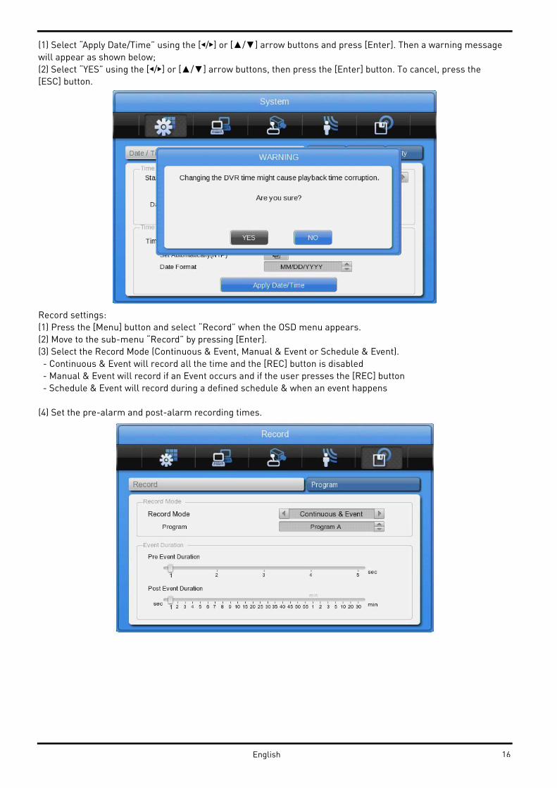
(1) Select “Apply Date/Time” using the [◀/▶] or [▲/▼] arrow buttons and press [Enter]. Then a warning message
will appear as shown below;
(2) Select “YES” using the [◀/▶] or [▲/▼] arrow buttons, then press the [Enter] button. To cancel, press the
[ESC] button.
Record settings:
(1) Press the [Menu] button and select “Record” when the OSD menu appears.
(2) Move to the sub-menu “Record” by pressing [Enter].
(3) Select the Record Mode (Continuous & Event, Manual & Event or Schedule & Event).
- Continuous & Event will record all the time and the [REC] button is disabled
- Manual & Event will record if an Event occurs and if the user presses the [REC] button
- Schedule & Event will record during a defined schedule & when an event happens
(4) Set the pre-alarm and post-alarm recording times.
16English
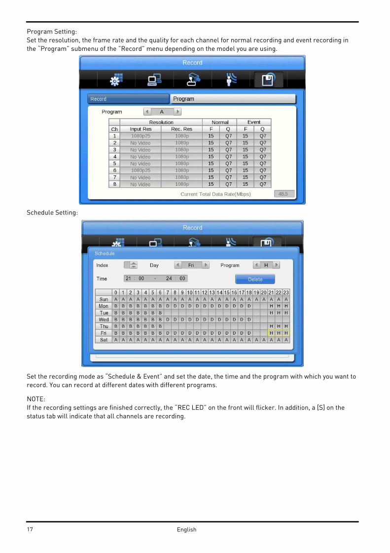
Program Setting:
Set the resolution, the frame rate and the quality for each channel for normal recording and event recording in
the “Program” submenu of the ”Record” menu depending on the model you are using.
Schedule Setting:
Set the recording mode as “Schedule & Event” and set the date, the time and the program with which you want to
record. You can record at different dates with different programs.
NOTE:
If the recording settings are finished correctly, the “REC LED” on the front will flicker. In addition, a [S] on the
status tab will indicate that all channels are recording.
17 English

4.4. Connecting and Configuring Ports
4.4.1. Wire Handling
When connecting a wire to a terminal block, follow the instructions below. Note the different types of wire that
can be used.
- Stranded wire : Peel 8~10 mm of the wiring cover and solder it. Wire gage should be
AWG 22~26.
- Solid wire : Peel 8~10 mm of the wiring cover and solder it. Wire gage should be AWG 20~26.
4.4.2. Inserting & removing wires
To insert & remove wires in the Terminal Block use a screwdriver as shown below in the diagram.
4.4.3. Connecting and configuring sensor connections
Specification:
18English
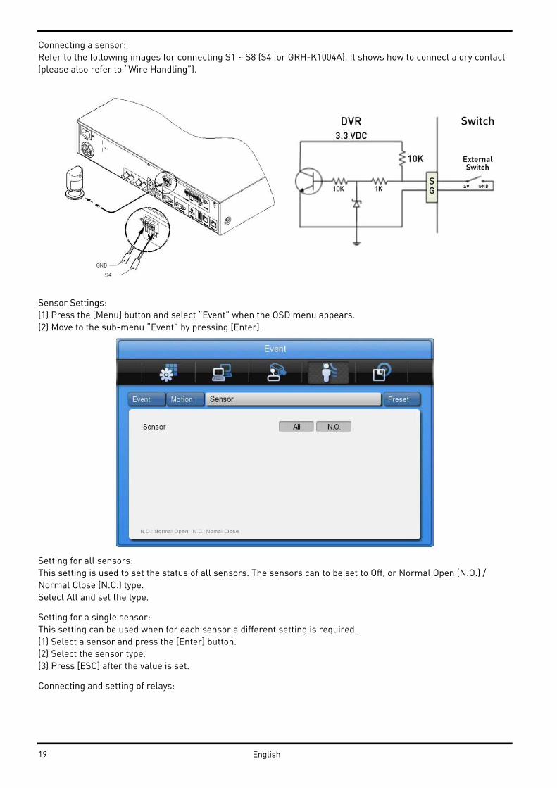
Connecting a sensor:
Refer to the following images for connecting S1 ~ S8 (S4 for GRH-K1004A). It shows how to connect a dry contact
(please also refer to “Wire Handling”).
Sensor Settings:
(1) Press the [Menu] button and select “Event” when the OSD menu appears.
(2) Move to the sub-menu “Event” by pressing [Enter].
Setting for all sensors:
This setting is used to set the status of all sensors. The sensors can to be set to Off, or Normal Open (N.O.) /
Normal Close (N.C.) type.
Select All and set the type.
Setting for a single sensor:
This setting can be used when for each sensor a different setting is required.
(1) Select a sensor and press the [Enter] button.
(2) Select the sensor type.
(3) Press [ESC] after the value is set.
Connecting and setting of relays:
19 English

Specification:
In order to run the relay output of the DVR normally, the following conditions are required.
Connecting relays:
Connect R1~R2 with reference to the following images which show how to connect a warning light. Please also
refer to “Wire Handling”.
Relay settings:
The DVR can activate relays from different events, such as sensor activation, motion detection or the loss of a
video signal. It is also possible to set system errors like Disk error, Disk full, authentication fail and DDNS
registration as triggers for such relay activation. If the Event Check is set to Custom, a schedule for the event
check can be created. In the case of using the control center software through a network, the relays can also be
activated from a remote location.
20English

Serial Port Configuration:
Configuring serial ports for Pan/Tilt/Zoom cameras:
The DVR supports the control of PTZ cameras over the COM port. For a list of supported protocols, please refer to
the list on the OSD configuration menu. The following image shows how to connect a PTZ camera to RS485
(COM2/COM3). When using another serial port, connect it while referring to the connection diagrams below.
Please also refer to “Wire Handling”.
Serial communication port diagram:
COM1 Connection (RS-232)
COM2/COM3 Connection (RS-485)
21 English
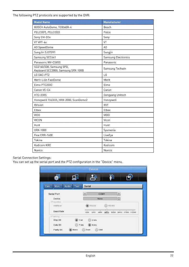
The following PTZ protocols are supported by the DVR:
Serial Connection Settings:
You can set up the serial port and the PTZ configuration in the “Device” menu.
22English

Under "Device" > "Serial", you can set the protocol, port, baud rate, parity bit, stop bit and data bit,
correspondingly to the settings in the PTZ camera.
After completion, switch to "Device" to select a desired channel from the camera menu, and connect the Camera
to the corresponding serial port by selecting the PTZ Port under the PTZ menu. Here you can also set up if the
PTZ should make use of its Home position, the Idle Time and the PTZ Address.
Connection to external device via Serial port:
Text input device connection (ATM / POS / Access Control):
Using the COM1/RS232 port, TEXT DATA can be recorded with a synchronised POS/ATM.
Like shown in the picture above, connect the COM1/RS232 (9pin D-Sub) and configure the Serial Connection and
Text in the “Device” menu.
23 English

Serial (COM1) Setup:
(1) Select “Device” in the OSD menu and move to this sub-menu by pressing [Enter].
(2) Select COM1 and configure the name/type of the device.
(3) Set up the value of Baud Rate/Parity/Stop bit/Data bit with the device.
Text Setup:
(1) Select “Device” in the OSD menu, and move to this sub-menu by pressing [Enter].
(2) Select “Text” and configure the relevant information.
(3) The DVR supports 2 different protocols (Starfinger 007 & VSI-Pro-Hydra) but can also be configured manually.
NOTE:
Since an external device cannot be recognised before being configured in this menu, please ask your dealer for
the correct data.
24English
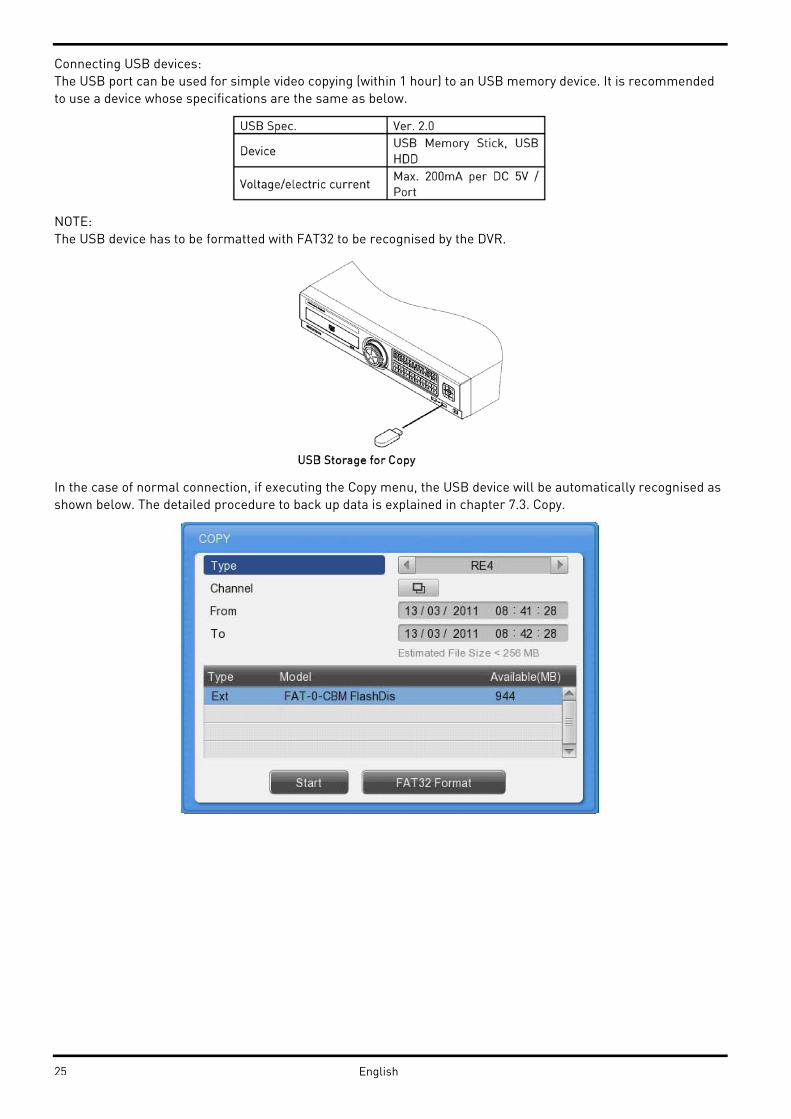
Connecting USB devices:
The USB port can be used for simple video copying (within 1 hour) to an USB memory device. It is recommended
to use a device whose specifications are the same as below.
NOTE:
The USB device has to be formatted with FAT32 to be recognised by the DVR.
In the case of normal connection, if executing the Copy menu, the USB device will be automatically recognised as
shown below. The detailed procedure to back up data is explained in chapter 7.3. Copy.
25 English

Connecting video outputs:
If the Video signal is looped through, the DVR notices this and sets the end resistance automatically. Please
ensure the correct end resistance setting of the device connected to the video out signal.
Connecting audio devices:
There are 4 RCA Audio Inputs and 1 RCA Output.
26English

4.4.4. HDD
Please refer to the following list for compliant HDDs:
HDD registration and format:
After mounting the HDD and booting the system, the “Disk Manager” will execute automatically. If not, please
check the connectivity of the HDD.
The Disk Manager can be manually executed in the menu “System” under “Disk”.
27 English
(1) Press the [Enter] button in “Disk Manager”.
(2) Using the [▲/▼] buttons, select the new HDD (Displayed [No] on Enabled item) and press [Enter].
(3) If you see the message for format, select [Yes]. If the HDD is already correctly formatted, this might not be
necessary.
(4) Press [ESC] to exit the “Disk Manager”.
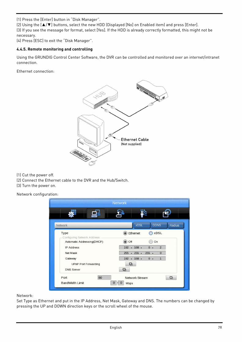
4.4.5. Remote monitoring and controlling
Using the GRUNDIG Control Center Software, the DVR can be controlled and monitored over an internet/intranet
connection.
Ethernet connection:
(1) Cut the power off.
(2) Connect the Ethernet cable to the DVR and the Hub/Switch.
(3) Turn the power on.
Network configuration:
Network:
Set Type as Ethernet and put in the IP Address, Net Mask, Gateway and DNS. The numbers can be changed by
pressing the UP and DOWN direction keys or the scroll wheel of the mouse.
28English

xDSL:
First, change the Ethernet Port under Network settings to xDSL and then move to the xDSL menu. After this, just
put in the ID and Password for your PPPoE connection. This data will be provided by your DSL provider.
DDNS:
The settings for the GRUNDIG DDNS server are already filled in. You will only need to set the time interval with
which the recorder should resend its IP information to the DDNS server. If your firewall and router settings are
correct, you should be able to access the DVR now from anywhere in the world by using the following address:
[last 6 digits of MAC address].grundig-ddns.eu
e.g. e312d45.grundig-ddns.eu
eSATA Device Connection:
You can connect almost any eSATA device to the DVR. The DVR does not supply power to the eSATA port;
therefore only devices with their own external power supply can be used.
NOTE:
The DVR will detect an eSATA connection, even though the DVR is already powered on. If not, it is recommended
to connect an eSATA device as follows:
1. Power off the DVR.
2. Connect the external device to the eSATA interface.
3. Power on the external device.
4. Power on the DVR.
GDS-R04A connection:
Connect the GDS-R04A with a Cat-6 cable to the [storage] port of the DVR. For the detailed configuration of the
GDS-R04A please refer to its user manual.
29 English

5. Menu Use
5.1. Menu Structure
The menu structure is shown in the image below. The settings for each menu are explained in the following
chapters.
5.2. Function Menu
To execute the Function menu, click the right button of the mouse or select the ‘FUNC’ button on the front panel.
The Function menu can be controlled by mouse or with the direction keys of the front panel. The function menu
differs for Multi channel Mode, Single channel, Mode Monitor Mode and Playback Mode.
Please refer to the picture below for the Function menu structure.
Function Bar in Multi-Channel Mode:
From left to right:
1. Access Main Menu
2. Select Multi Mode View
3. Start Sequence
4. Backup Menu
5. Search
6. Enter Playback Mode
7. Key-Lock function (will disable the front panel buttons of the device)
8. Log Out
9. Shutdown
Function Bar in Single Channel Mode:
30 English
From left to right:
1. Access Main Menu
2. Select Multi Mode View
3. Start Sequence
4. Digital Zoom
5. PTZ Control
6. Backup Data
7. Search
8. Enter Playback Mode
9. Key-Lock function (will disable the front panel buttons of the device)
10. Log Out
11. Shutdown
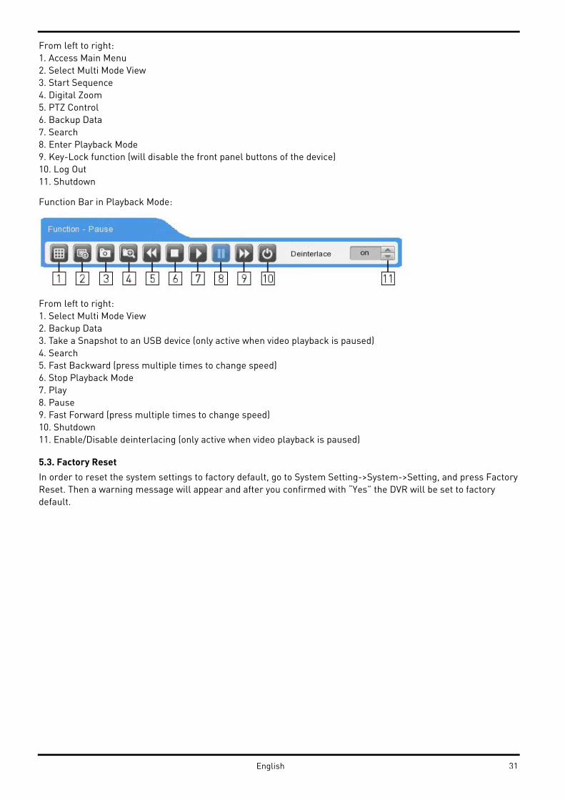
Function Bar in Playback Mode:
From left to right:
1. Select Multi Mode View
2. Backup Data
3. Take a Snapshot to an USB device (only active when video playback is paused)
4. Search
5. Fast Backward (press multiple times to change speed)
6. Stop Playback Mode
7. Play
8. Pause
9. Fast Forward (press multiple times to change speed)
10. Shutdown
11. Enable/Disable deinterlacing (only active when video playback is paused)
5.3. Factory Reset
In order to reset the system settings to factory default, go to System Setting->System->Setting, and press Factory
Reset. Then a warning message will appear and after you confirmed with “Yes” the DVR will be set to factory
default.
31English

FACTORY DEFAULT
System:
32 English

Network:
33English

Device:
Event:
34 English
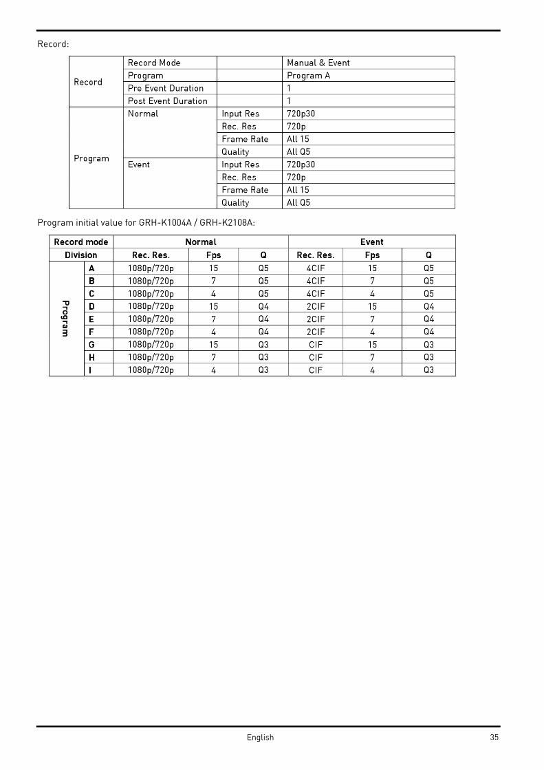
Record:
Program initial value for GRH-K1004A / GRH-K2108A:
35English

6. Monitoring
All HD-SDI video image channels connected to the DVR are displayed on the screen after booting the DVR.
6.1. Basic Screen
After the power connection is established, the DVR will boot
automatically. After booting, the user needs to put in his user
password. In the default settings, only the admin has the rights
to see the channels, therefore no user will see any video at the
first boot.
Depending on the model you will either see a 4ch or 8ch split
view.
6.2. Single Full Screen Mode
Press the wanted channel number or click with the mouse on
the wanted channel. Double-click with the mouse to return to
the previous multi-channel view.
You can select different Multi-channel views by clicking the
[Multi] button on the front panel or the [Multi] button in the
function bar.
6.3. Multi Screen Mode
Press [MULTI] for multi channel display or click the “Display” icon in the Function menu. Every time you press the
[MULTI] button, the screen mode will change.
For GRH-K1004A you only have the 1-4 channel multiview.
For GRH-K2108A you also have the 5-8, 4C & 1~8 multiview.
6.4. Screen Description
The status bar from the monitoring screen shows the DVR’s current status which includes Date/Time, Record,
Motion/Sensor Detection, Manual Record, Text Input and HDD’s Record capacity.
36 English
6.5. Sequence Mode
By pressing the [SEQ] button a user defined sequence will start switching between single channels and division
views after a preconfigured time.
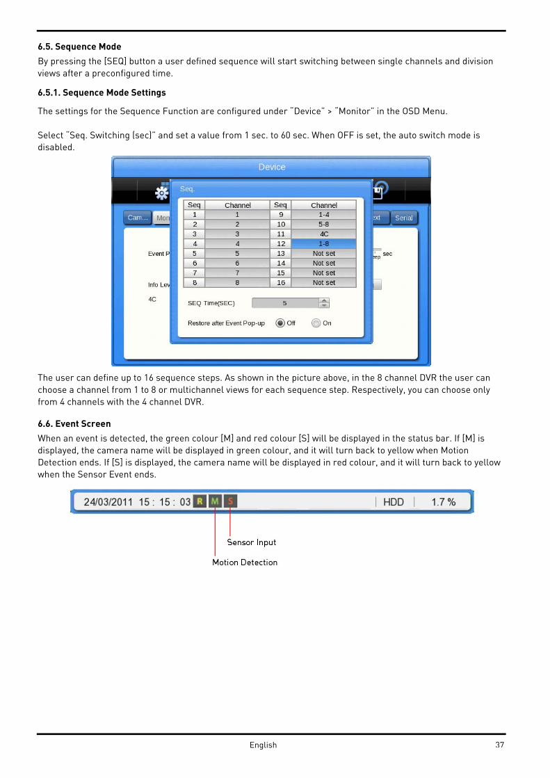
6.5.1. Sequence Mode Settings
The settings for the Sequence Function are configured under “Device” > “Monitor” in the OSD Menu.
Select “Seq. Switching (sec)” and set a value from 1 sec. to 60 sec. When OFF is set, the auto switch mode is
disabled.
The user can define up to 16 sequence steps. As shown in the picture above, in the 8 channel DVR the user can
choose a channel from 1 to 8 or multichannel views for each sequence step. Respectively, you can choose only
from 4 channels with the 4 channel DVR.
6.6. Event Screen
When an event is detected, the green colour [M] and red colour [S] will be displayed in the status bar. If [M] is
displayed, the camera name will be displayed in green colour, and it will turn back to yellow when Motion
Detection ends. If [S] is displayed, the camera name will be displayed in red colour, and it will turn back to yellow
when the Sensor Event ends.
37English

In the “Monitor” menu you can define an Event Pop-up time. If this is set, the DVR will display only the channels
on which an event occurred. For example, when on 3 channels motion was detected, a 4 division screen will be
displayed on the screen, including these 3 channels. Press any button to return to the original channel, or wait
until the Event Pop-up time ends.
1. If Event Pop-up (sec) is set to "Off", the Event Pop-up will not operate.
2. If Event Pop-up (sec) is set to "Keep", it does not return to the previous screen until you press a button.
6.7. Zoom Screen Mode
- In the single full screen mode, press the [FUNC] button and the D-Zoom button, then use the [+] button to
zoom in the image.
- The default zoom screen is located in a central position when pressing the [ZOOM] button. You can have a
digital zoom of up to 18x of the original picture.
- Use the direction keys to move the image selection.
- Press [-] to return to the original screen.
6.8. Pause Live Screen
- Press [PAUSE] to pause the live screen and press [PAUSE] again to return to live screen.
38 English
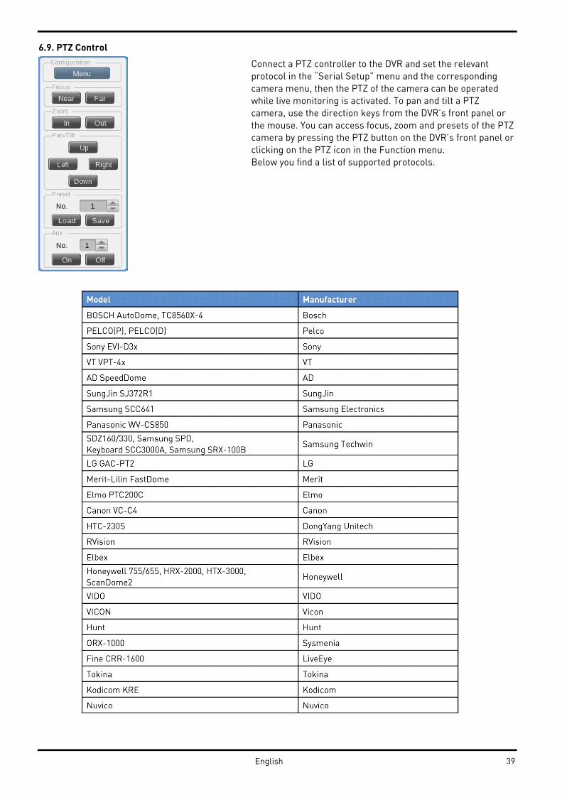
6.9. PTZ Control
Connect a PTZ controller to the DVR and set the relevant
protocol in the “Serial Setup” menu and the corresponding
camera menu, then the PTZ of the camera can be operated
while live monitoring is activated. To pan and tilt a PTZ
camera, use the direction keys from the DVR’s front panel or
the mouse. You can access focus, zoom and presets of the PTZ
camera by pressing the PTZ button on the DVR’s front panel or
clicking on the PTZ icon in the Function menu.
Below you find a list of supported protocols.
39English

- Press the button of the desired channel, or select the channel with the mouse.
- Press the PTZ button from the front panel or click on the PTZ icon in the Function menu with the mouse.
- The PTZ menu (Zoom/Focus, Load Preset, Save Preset) will appear.
- Then press the [Enter] button or click on the mouse.
6.9.1. Pan/Tilt
The Pan/Tilt function is directly activated after you have chosen a PTZ camera in single monitor mode. You can
control the PTZ with the front panel direction buttons, or with the USB mouse by clicking on the screen.
Depending on the distance to the central cross, the PTZ will move into the direction of the mouse click.
6.9.2. Zoom/Focus
This menu is used to control the Zoom & Focus function in real-time monitoring mode.
- Select Z/F (Zoom/Focus) from the PTZ mode.
- Control Zoom/Focus through the direction keys on front of the DVR or use the scroll wheel of the mouse.
6.9.3. Loading Preset
This menu is used to move the PTZ camera into a Preset position during real-time monitoring mode.
- Use the Up / Down buttons or the mouse wheel to select the Preset Number.
- Once Preset is configured, please select [Load] and then press [Enter].
6.9.4. Save Preset
This menu is used to set a new Preset position during real-time monitoring mode.
- Control the PTZ camera location by using the ‘Pan/Tilt’ menu and the ‘Zoom/Focus’ menu.
- Use the Up / Down buttons or the mouse wheel to select the Preset Number.
- Once the preset position is configured, select [Save] and then press [Enter].
6.9.5. Auxiliary On
This menu is used to utilise specific functions of a PTZ device during real-time monitoring mode.
- Use the Up / Down buttons or the mouse wheel to select the Aux Number.
- Select the relevant Number button for this specific function (Up to 16 functions of the PTZ camera can be
controlled with the Aux Function.)
6.9.6. Auxiliary Off
This menu is used to stop operation of a specific function of the PTZ device.
- Use the Up / Down buttons or the mouse wheel to select the Aux Number.
- Select Off and press the [Enter] button or click on the mouse.
6.9.7. Menu
With this function you can connect to the PTZ camera's menu. Use the Up/Down/Left/Right and the Enter key on
the front panel of the DVR to adjust settings in the menu, and press the [ESC] button to exit the menu.
NOTE: After leaving the PTZ OSD menu, you will need to inform the DVR about this, as the DVR is not able to
recognise this by itself. Therefore, you will find an [Exit] button on the screen. You can click with the mouse or use
the [PTZ] button on the front panel to activate this button. Afterwards, the PTZ menu of the DVR will be visible
again and can be left by right-clicking with the mouse or pressing the [ESC] button.
40 English

7. Playback
7.1. Playback Mode
7.1.1. Playback on Standard monitor (16 / 9 / 4 division)
- Please press the [PLAY] button in monitoring mode or click the [PLAY] button in the Function menu with the
mouse.
- When pressing the [PLAY] button or the [FWD] button, the video plays in forward direction at 1× speed.
- When pressing the [REW] button, the video plays backwards at 1× speed.
- When pressing the Playback button in a multi-division monitor mode, it plays the recorded data for all viewable
channels.
7.1.2. Playback function
PLAY:
Playback 1× speed Multichannel video will play when pressing the [PLAY] button in Multichannel monitor mode.
PAUSE:
Pause the video temporarily.
STOP:
Stops the Playback and the DVR returns to live view.
FWD:
Playback speed will be changed (x1, x2, x4, x8, x16, x32, x64, x1/2, x1, x2, x4 – in order). When pressing the [FWD]
button in live view mode, the DVR plays back the recorded video from 1 minute ago. Playback speed can be
changed by pressing the [FWD] button.
REW:
Reverse playback speed will be changed (x1, x2, x4, x8, x16, x32, x64, x1/2, x1, x2, x4 - in order). When pushing the
[REW] button in the live view mode, the DVR plays back the video from 1 minute ago. Playback speed can be
changed by pressing the [REW] button.
STEP FORWARD:
When pressing the [FWD] button while playback is paused, the video will jump to the next frame. Press [PLAY] to
return to normal playback mode.
STEP REWIND:
When pressing the [REW] button while the playback is paused, the video will jump to the previous frame. Push
[PLAY] to return to normal playback.
1/2 REWIND:
Plays at half speed in reverse direction.
1/2 FORWARD:
Plays at half speed in forward direction.
Jog Dial:
The Jog Dial can be used to control the video playback. The outer wheel controls the speed of the playback. The
inner wheel can be used to control the Fast-forward function and the Rewind function.
41 English

7.2. Search Mode
The DVR supports 4 different modes to search for video material (Time, Calendar, Event, Thumbnail). Press the
[SEAR] button on the front panel or the search icon in the Function menu to access the Search menu.
7.2.1. Time Search
Start-REC Time:
The date and time of the first recording
End-REC Time:
The date and time of the last recording
Search Time:
Select the date and time to play back
Search:
Start the search
Select the date and time to search for. After pressing the [Search] button, the video will play back at the
requested position.
42English
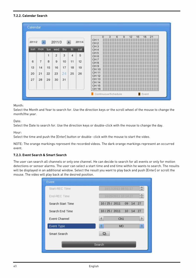
7.2.2. Calendar Search
Month:
Select the Month and Year to search for. Use the direction keys or the scroll wheel of the mouse to change the
month/the year.
Date:
Select the Date to search for. Use the direction keys or double-click with the mouse to change the day.
Hour:
Select the time and push the [Enter] button or double- click with the mouse to start the video.
NOTE: The orange markings represent the recorded videos. The dark orange markings represent an occurred
event.
7.2.3. Event Search & Smart Search
The user can search all channels or only one channel. He can decide to search for all events or only for motion
detections or sensor alarms. The user can select a start time and end time within he wants to search. The results
will be displayed in an additional window. Select the result you want to play back and push [Enter] or scroll the
mouse. The video will play back at the desired position.
43 English

Start-REC Time:
Starting date and time of the first recording
End-REC Time:
The date and time of the last recording
Search Start Time:
Input the start date and time for search with the direction buttons, press [Enter] and change the value with the Up
/ Down buttons. With the mouse, click and scroll the wheel.
Search End Time:
Input the end date and time for search with the direction buttons, press [Enter] and change the value with the Up
/ Down buttons. With the mouse, click and scroll the wheel.
Event Channel:
Select the channel for the search:
- GRH-K2108A: from Ch1 to Ch8
- GRH-K1004A: from Ch1 to Ch4
Event Type:
Select the event type for the search. Choose between:
ALL, MD, SENSOR, V- LOSS, TEXT
Smart Search:
If you select only one channel and motion detection as event, you will be able to define a motion area that will be
searched. Even if you have motion detection activated for the full screen, only results in this area will be
displayed. This can be very helpful if you want to minimise search results.
44English

7.2.4. Thumbnail Search
Use this search mode to search by thumbnail preview pictures. Select the channel, date and time and the time
interval to create 16 thumbnails of the video.
Channel:
Select the channel and change the value with the direction keys or the mouse wheel.
Start Time:
Input the date and time for the starting point and change the value using the Up / Down direction keys or the
mouse wheel.
Interval:
Set the interval value using the Up / Down direction keys or the mouse wheel. You can change the interval from 1-
60 and you can choose between seconds, minutes, hours & days.
View video:
When pressing the [Search] button, 16 thumbnail previews will be shown based on the start time and interval.
Press [FUNC] to return to the search or use the mouse wheel.
Select video:
Use the direction keys to move the blue selection frame and press the [Enter] button to start playback.
Alternatively, select a thumbnail with the left mouse button and start the playback with an additional mouse click.
7.3. Copy
The Copy function is used to back up video material on USB devices or CD/DVDs. For USB devices you can select
between the RE4 (multichannel) and AVI (only 1 channel) video format and store it on a FAT32 formatted device.
In the user authorisation you can define which user has the right to back up the video. For this please refer to
chapter 8.1.3. User Setup.
To use the copy function, press [COPY] or click the Copy button in the Function menu.
NOTE: The multichannel format always includes a miniplayer.exe file that can play back the video without the
need to install any program. You have also access to the logfile with this miniplayer.
NOTE: When accessing the Copy function from Playback, the actual playback time will be copied to the Start time
field and the Stop time field will be 1 minute later. With these settings an easy adjustment of the backup time is
possible.
45 English

7.3.1. CD/DVD
This is the copy function if you use a recordable CD or a DVD. Please insert the recordable CD or DVD first before
you start the backup menu. The CD or DVD will be automatically detected.
Type:
Select CD/DVD by using the direction keys or the mouse wheel.
Channel:
In a pop-up window the user can select some or all channels to be backed up. Enter or use the mouse wheel to
access the channel selector.
From:
Select the start date and time to copy using the Up / Down direction keys or the mouse scroll wheel.
To:
Select the end date and time to copy using the Up / Down direction keys or the mouse scroll wheel.
Select Disk:
Select the media to copy using the [Enter] button on Select Disk.
Start:
Starts to copy. Press the [Start] button with [Enter] or click with the left button of the mouse.
Please refer to the supported media list below.
DVD-R manufacturer (DVD+R is not supported):
- Mitsubishi (×16 recommended)
- TDK (×16 recommended)
- Imation (×16 recommended)
- Sony (×16 recommended)
CD-R Manufacturer:
- Mitsubishi (×52 recommended)
- TDK (×52 recommended)
- Imation (×52 recommended)
- Sony (×48 recommended)
46English

7.3.2. RE4
The RE4 format can be backed up on external HDDs and USB Flash drives. Together with the video a Mini player
will be copied to the Storage device to be able to view the RE4 format. You can also open the RE4 file with the
GRUNDIG Control Center.
Select the channel you want to record and press [Enter] or use the mouse to open the channel selector as shown
below.
Type:
Select RE4 using the direction keys or the mouse wheel.
Channel:
To pop up the channel selection window, press [Enter] or use the mouse.
Select Channel:
The user can select some or all channels. After selecting the channel, press [Enter] or click the left button of the
mouse.
From:
Set the start date or time to copy. Use the direction keys or the mouse wheel to change the values.
To:
Set the end date or time to copy. Use the direction keys or the mouse wheel to change the values.
47 English
Select disk:
Select the media you want to copy to. Press [Enter] on the Disk list or click the mouse.
Start:
Starts the backup. Press [Enter] or click the mouse.
NOTE: If the backup is interrupted, the backup files will not be playable on a PC.
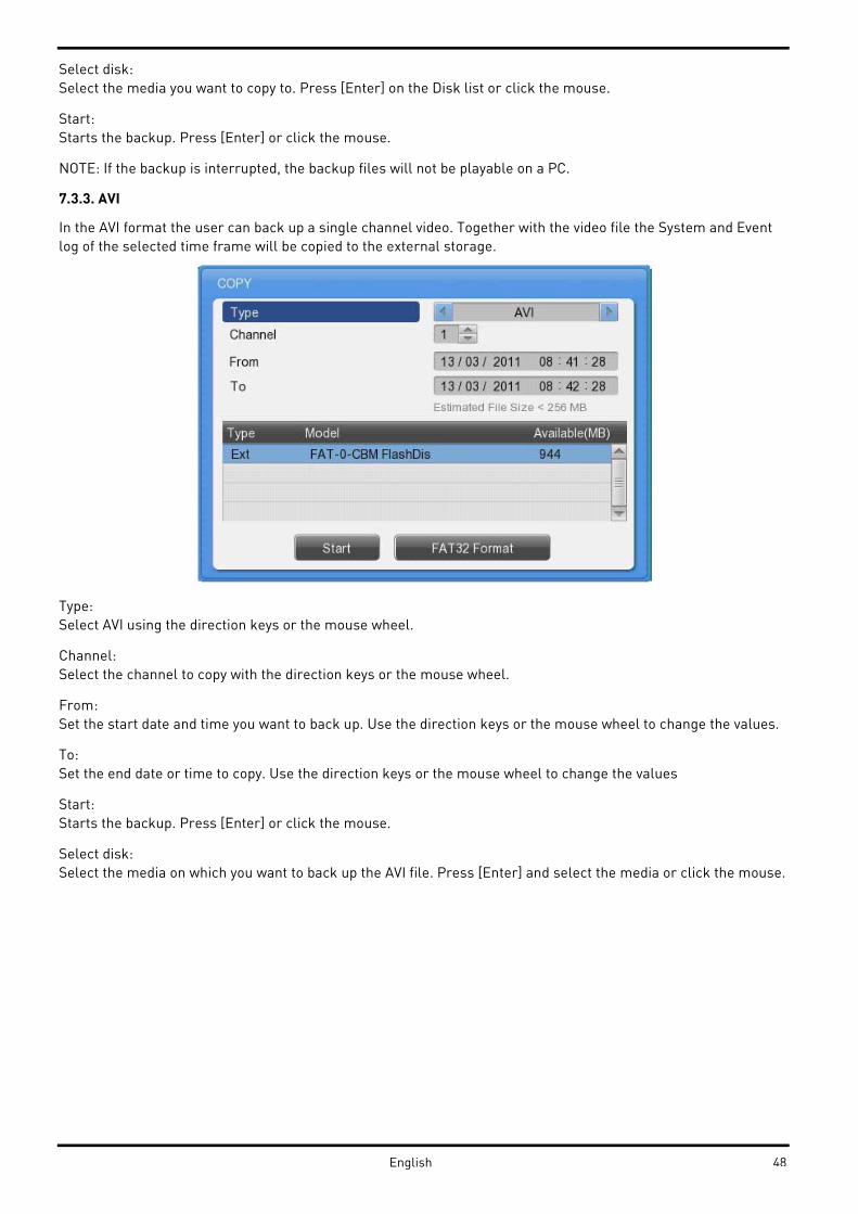
7.3.3. AVI
In the AVI format the user can back up a single channel video. Together with the video file the System and Event
log of the selected time frame will be copied to the external storage.
Type:
Select AVI using the direction keys or the mouse wheel.
Channel:
Select the channel to copy with the direction keys or the mouse wheel.
From:
Set the start date and time you want to back up. Use the direction keys or the mouse wheel to change the values.
To:
Set the end date or time to copy. Use the direction keys or the mouse wheel to change the values
Start:
Starts the backup. Press [Enter] or click the mouse.
Select disk:
Select the media on which you want to back up the AVI file. Press [Enter] and select the media or click the mouse.
48English

8. Configuration
8.1. System Setup
Time, Disk and Authority settings and miscellaneous settings can be configured here.
8.1.1. Date/Time
The Date and Time setting should be configured prior to any recording.
The Time configuration is very important to protect the recording data. Changing the time during recording is not
recommended. The factory default setting for the time is “UTC 00:00 Dublin”.
Time Setup:
Caution: While recording, changing the system time will affect a time change for all previously recorded video
data. Therefore, we recommend to back up the recorded video before changing the system time.
- Press “Main Menu” in the Function menu or the [MENU] button on the front panel.
- Select the “System” menu.
- Select “Date/Time” in the System menu. The Date/Time configuration will be opened.
- Use the directional keys or the mouse to change the values.
Time Zone / Standard Time:
Use the Left / Right direction keys or the mouse wheel. To return to the previous menu, press [ESC] or click the
right mouse button.
Daylight Saving:
This menu is synchronised with the time zone configuration menu. When a daylight saving area is set, this
function is activated. The daylight saving applicable area is working in conformity with the time zone of Microsoft
Windows.
49 English

Custom DST:
You can also use a custom DST. Select a fixed day of a week (first Tuesday of March) or the day of a month (24th of
March) to select when the switch should happen. You can also define the exact time, when it should happen. This
can be used if you want to change the time not in the middle of the night, but maybe on the noon of the next day,
so you have enough time to search for any events using the “old” time.
Date format (Type):
Change the date format between “MM/DD/YYYY”, “YYYY/MM/DD” and “DD/MM/YYYY” by using the Left / Right
direction keys or the mouse wheel.
Start / End Time:
With the Left / Right direction keys, you can move to year, month, day, hour in order. Each configuration can be
changed with the Up / Down direction keys or the mouse wheel.
50English

Apply:
When pushing the “Apply Date/Time” button, you will see the message box shown below.
NOTE:
Except for the "Date/Time" configuration, all configurations are saved automatically. The “Date/Time”
configuration can have a critical effect on the HDD recording file system, therefore the user has to confirm these
changes. Press “Yes” if you want to confirm or press “No” and return to the previous menu.
NTP Setup / Set Automatically (NTP):
The NTP (Network Time Protocol) synchronises the time of all connected devices. The DVR can be set to client
mode or server mode or to both modes at the same time.
Sync with NTP:
Enable or disable the NTP function.
NTP Mode:
Configure the NTP mode of the DVR – Client / Server / Both
Caution: When using the NTP client mode, the user must set the NTP to "On".
NTP Server Loc.:
If the DVR is in client NTP mode, this function is enabled. Configure the IP address of a local network NTP server
or select “Public” if the NTP server is a public one.
51 English

NTP Local server IP:
Input the IP address of the local NTP server or a DVR that is working in NTP server mode.
Interval:
Configure the interval of the time synchronisation.
8.1.2. Disk
In the “Disk” menu everything regarding the hard disk of the DVR can be configured. Here you can also use the
Disk Manager to format HDDs.
Overwrite (Auto Deletion):
If there is no space left in the HDD, old data will be overwritten automatically.
Disk Full Alarm Warning:
If the mounted Disk has reached the selected percentage, an alarm warning will be send to the user.
Block Playback:
The Block Playback function can be used to decline access to recorded video material. If the Block Playback is set
to 2 days, only the last 2 days can be seen and backed up with the recorder. Everything before these 2 days cannot
be accessed.
Delete Data:
The Block Playback function only denies the playback access to the recorded data, but the data is still available
on the HDD. If you have menu access, you could get access to the playback by deactivating the Block Playback
afterwards. Sometimes it is law that you need to delete the data. Therefore, you can activate the Delete Data
function and all data will be erased permanently.
52English

Disk Manager:
“Disk Manager” is the menu for the management of internal or external HDDs (hard disk drives). You can see the
type, name, the bad block status and the size of the HDD in this menu. You can also select if the HDD is enabled
for recording or not.
NOTE: If you enable a HDD to record, you will be asked whether the HDD should be formatted.
Type:
Displays the location or type of disk ( Int A (Internal A HDD), Int B (Internal B HDD), Ext (External HDD) ).
Model:
HDD model name
Bad Blk:
Displays the number of bad blocks of the HDD.
Size:
Displays the HDD size in MB.
Enabled:
Enables a HDD for recording (“Yes”: Enabled / “No”: Disabled).
To enable a HDD, select it and change the status from NO to YES, by either pressing the “Enter” button on the
front panel or changing it with the mouse wheel.
The following request window will pop up:
Caution: This Disk can be added without format. Nevertheless, do you want to format this disk?
- If you select NO, the HDD will not be formatted.
NOTE: If the HDD was already used in a GRUNDIG DVR and was formatted correctly, it will be available for
recording even if you selected NO. All previously recorded videos will be also available.
- If you select YES, all data on the HDD will be erased and the HDD will be used for recording.
If you set the HDD status to NO, a window will pop up:
Disk will be removed.
- If you select YES, the message “Recording disk removed” will appear at the bottom of the screen and the status
of the HDD is set to NO. The HDD will not be used for recording.
- If you select NO, the HDD will be used without any change and the message "Disk reused for recording" will
appear at the bottom of the screen.
53 English

Disk Status:
In the “Disk Status” menu you can check the temperature and status of the installed HDDs.
Mirroring (only GDV-C4416A & GDV-B8832A):
In the mirroring option you can activate the RAID function. You can choose between three options. You need to
use identical HDDs to activate this option and ensure a flawless working condition.
- DVR: The HDDs inside the DVR will be connected as one RAID (Redundant Array of Independent / Inexpensive
Disks). Please note that HDD1 and HDD3 will form one pair and HDD2 and HDD4 another pair.
- GDS: If you have attached the Network storage device GDS-R04A, it can be set up to mirror its data here.
- Both: All HDDs inside the DVR and inside the GDS-R04A storage will be mirrored.
Please note that you need to disable all HDDs before you can activate the mirroring. All HDDs also need to be
formatted.
After you have activated the mirroring the mirror HDD will be shown with an (M) at the end of its name. To format
both HDDs you need only to format the partner HDD.
54English

NOTE:
The recording performance of the DVR will be reduced when the mirror function is activated.
8.1.3. User Setup
The user setup is only visible for the administrator. Users can only change their passwords here.
In the user setup you can define which user has which rights. You can choose that users are only allowed to
access defined channels and can only execute defined functions. Here you can change the user name and the
password.
User ID:
Here you can select which user you want to edit.
User Name:
Change the user name here. This name can then be used to enter the DVR directly or over the Ethernet
connection.
Change Password:
The password can be up to 8 digits long. To ensure you did not misspell the password, you have to enter the
password twice. Press ”Change” when the password is finished. After that, a message window will be shown and
you have to confirm the password change.
Access rights:
Here you define which rights the user has. The administrator has always all of the rights and this cannot be
changed. In the default settings the users do not have any right to see any channel or do anything. The
administrator needs to give them rights first.
55 English

Functions:
Here you can define which functions of the DVR the user can access.
Menu: gives the user the right to access the configuration menu. (He has less rights than the admin but can
change almost anything.)
PTZ: If set to YES, the user has the right to control PTZ cameras.
Relay: If set to YES, the user has the right to activate the relays of the DVR.
Playback: If set to YES, the user has the right to access the Playback.
Power Off: If set to YES, the user has the right to turn off the DVR.
Copy: If set to YES the user has the right to backup video.
N/MIC: If set to YES, the user has the right to use the microphone function over the network.
Channel rights:
Here you can define which channels the user can see under Live & Playback. Coverted channels will also be
invisible in search results and backup files.
Auto Log-out time:
Every user can have his own auto-log-out time. With this function you can, for example, limit the admin access to
2 minutes. So even if you forget to log-out, the access to the DVR will not be possible without the admin password.
But you can also create a user with infinity log-out time (set to 0), so that you can have a “guest” account that will
show defined channels all the time without any special function rights.
56English

NOTE:
The password prompt will be visible after the DVR has started and when nobody is logged in. After that, the user
that is logged in has access to all the rights defined in user setup.
Change the Password:
Select Change P/W for the user whose password should be changed. The password input box will be displayed.
The password can be set with the direction keys on the front of the DVR or with the mouse in the text input
window.
NOTE:
The Admin Password is “1234” in factory default. For user 1 to 10 the password is (in order) “1111”,”2222”, ... and
for user 10 it is “0000”.
Change the Password:
Select Change P/W for the user whose password should be changed. The password input box will be displayed.
The password can be set with the direction keys on the front of the DVR or the mouse in the text input window.
57 English

User setup page for users:
A user will see a different page than the administrator. He will be only able to change hisits own password:
8.1.4. Utility
Configure the name of the DVR, the remote control ID and Language.
DVR Alias:
Set the name of the DVR. This name will be shown when accessing the DVR via a network.
DVR Keyboard ID:
This menu is for setting the address of the keyboard when using all functions of the DVR with the keyboard.
Factory default is “1”. If the user wants to control various DVRs with one keyboard, each address should be set
with a different value.
Remote Controller ID:
Maximally 16 remote control IDs can be set. One remote control can be used to manage all the 16 DVRs.
Registration order for the remote control:
1. Make the remote control point in the direction of the DVR.
2. Press the ID button several times to match the ID of the remote control to the DVR.
3. If the IDs are matched correctly, the DVR buzzes.
4. Now you can use the remote control.
58English

Language:
Select the language you would like to use.
Firmware Update:
You can update the firmware by a USB Memory device.
- Insert a USB memory device including the firmware file to the USB port.
- Press the Firmware Update button.
- Select [YES] in the pop-up window.
NOTE: Only the administrator is allowed to perform a Firmware Update.
- The system will reboot.
- Firmware update is done.
System Log:
The system log shows the boot status of the system and any changes regarding users and the DVR configuration.
59 English
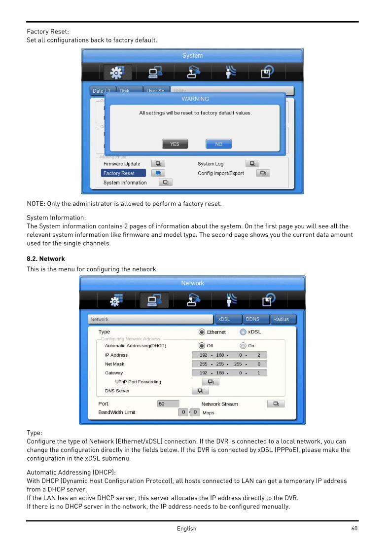
Factory Reset:
Set all configurations back to factory default.
NOTE: Only the administrator is allowed to perform a factory reset.
System Information:
The System information contains 2 pages of information about the system. On the first page you will see all the
relevant system information like firmware and model type. The second page shows you the current data amount
used for the single channels.
8.2. Network
This is the menu for configuring the network.
Type:
Configure the type of Network (Ethernet/xDSL) connection. If the DVR is connected to a local network, you can
change the configuration directly in the fields below. If the DVR is connected by xDSL (PPPoE), please make the
configuration in the xDSL submenu.
Automatic Addressing (DHCP):
With DHCP (Dynamic Host Configuration Protocol), all hosts connected to LAN can get a temporary IP address
from a DHCP server.
If the LAN has an active DHCP server, this server allocates the IP address directly to the DVR.
If there is no DHCP server in the network, the IP address needs to be configured manually.
60English

IP Address:
The IP Address is for connection between the DVR and the Control Center and also for the web connection with
the WebViewer (Net Mask and Gateway need to be configured if you want to access the DVR over the Internet.)
Net Mask:
The Net Mask determines the range of the IP addresses which are available for use. You should receive the
correct data from the network administrator.
Gateway:
The Gateway is necessary for different types of network connections. You should receive the correct data from the
network administrator.
UPnP (Universal Plug and play):
This very helpful feature can be used if you do not want to configure your network forwarding ports manually. If
activated, the DVR will instruct your router automatically to forward all requests coming to the defined port. Set
the Port Forwarding to “On” to activate this feature in the Pop Up Window. The status of the UPnP forwarding will
be shown in the Status field.
DNS Server:
DNS is a network service used to rename IP addresses (Domain Name Server) and it should be received from the
network administrator.
Port:
The port is necessary for the connection to the Control Center Software and the WebViewer. The factory default
setting is Port 80. If you want to connect to the DVR through the internet and behind the router, this is the port
you will need to forward in your router.
Please make also sure that your firewall is not preventing the access to this port.
Bandwidth Limit:
In this menu the bandwidth used for video transmission can be limited. You can define the bandwidth between
0.03 Mbps and 99.99 Mbps. Contact the network administrator for further information on bandwidth limitation.
61 English
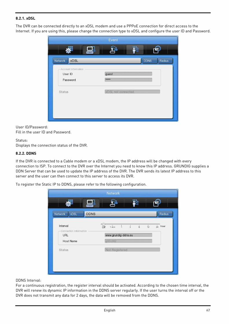
8.2.1. xDSL
The DVR can be connected directly to an xDSL modem and use a PPPoE connection for direct access to the
Internet. If you are using this, please change the connection type to xDSL and configure the user ID and Password.
User ID/Password:
Fill in the user ID and Password.
Status:
Displays the connection status of the DVR.
8.2.2. DDNS
If the DVR is connected to a Cable modem or a xDSL modem, the IP address will be changed with every
connection to ISP. To connect to the DVR over the Internet you need to know this IP address. GRUNDIG supplies a
DDN Server that can be used to update the IP address of the DVR. The DVR sends its latest IP address to this
server and the user can then connect to this server to access its DVR.
To register the Static IP to DDNS, please refer to the following configuration.
DDNS Interval:
For a continuous registration, the register interval should be activated. According to the chosen time interval, the
DVR will renew its dynamic IP information in the DDNS server regularly. If the user turns the interval off or the
DVR does not transmit any data for 2 days, the data will be removed from the DDNS.
62English
DDNS URL:
This menu is for setting a server address where the DVR can register its dynamic IP address. The DDNS address,
on which GRUNDIG is operating now, is: www.grundig-ddns.eu.
You can access the DVR now over the internet and the Control Center Software through the following address:
[last 6 digits of the MAC address].grundig-ddns.eu
(example: g02c362.grundig-ddns.eu)
The MAC address is printed on the box label and on the backside of the DVR.
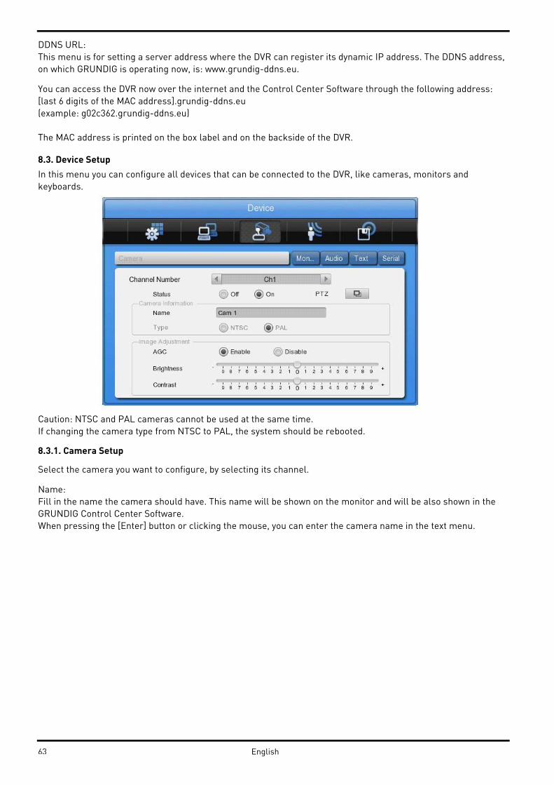
8.3. Device Setup
In this menu you can configure all devices that can be connected to the DVR, like cameras, monitors and
keyboards.
Caution: NTSC and PAL cameras cannot be used at the same time.
If changing the camera type from NTSC to PAL, the system should be rebooted.
8.3.1. Camera Setup
Select the camera you want to configure, by selecting its channel.
Name:
Fill in the name the camera should have. This name will be shown on the monitor and will be also shown in the
GRUNDIG Control Center Software.
When pressing the [Enter] button or clicking the mouse, you can enter the camera name in the text menu.
63 English
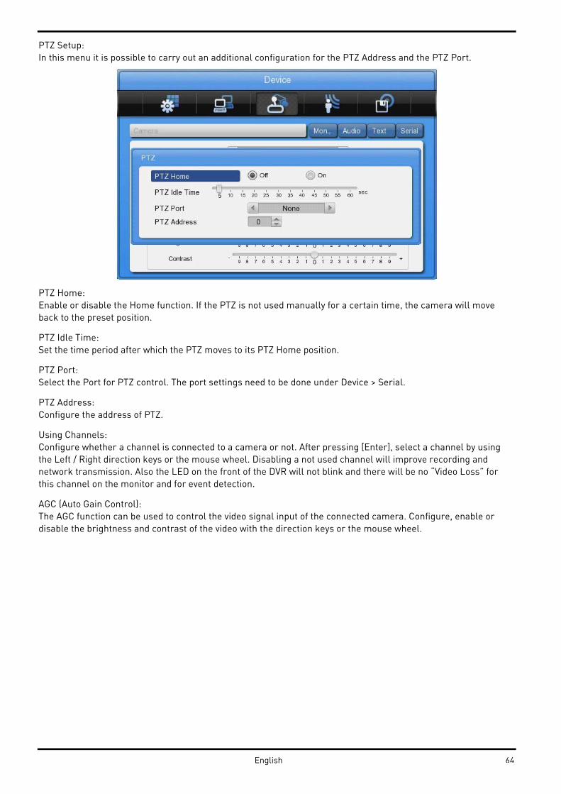
PTZ Setup:
In this menu it is possible to carry out an additional configuration for the PTZ Address and the PTZ Port.
PTZ Home:
Enable or disable the Home function. If the PTZ is not used manually for a certain time, the camera will move
back to the preset position.
PTZ Idle Time:
Set the time period after which the PTZ moves to its PTZ Home position.
PTZ Port:
Select the Port for PTZ control. The port settings need to be done under Device > Serial.
PTZ Address:
Configure the address of PTZ.
Using Channels:
Configure whether a channel is connected to a camera or not. After pressing [Enter], select a channel by using
the Left / Right direction keys or the mouse wheel. Disabling a not used channel will improve recording and
network transmission. Also the LED on the front of the DVR will not blink and there will be no “Video Loss” for
this channel on the monitor and for event detection.
AGC (Auto Gain Control):
The AGC function can be used to control the video signal input of the connected camera. Configure, enable or
disable the brightness and contrast of the video with the direction keys or the mouse wheel.
64English
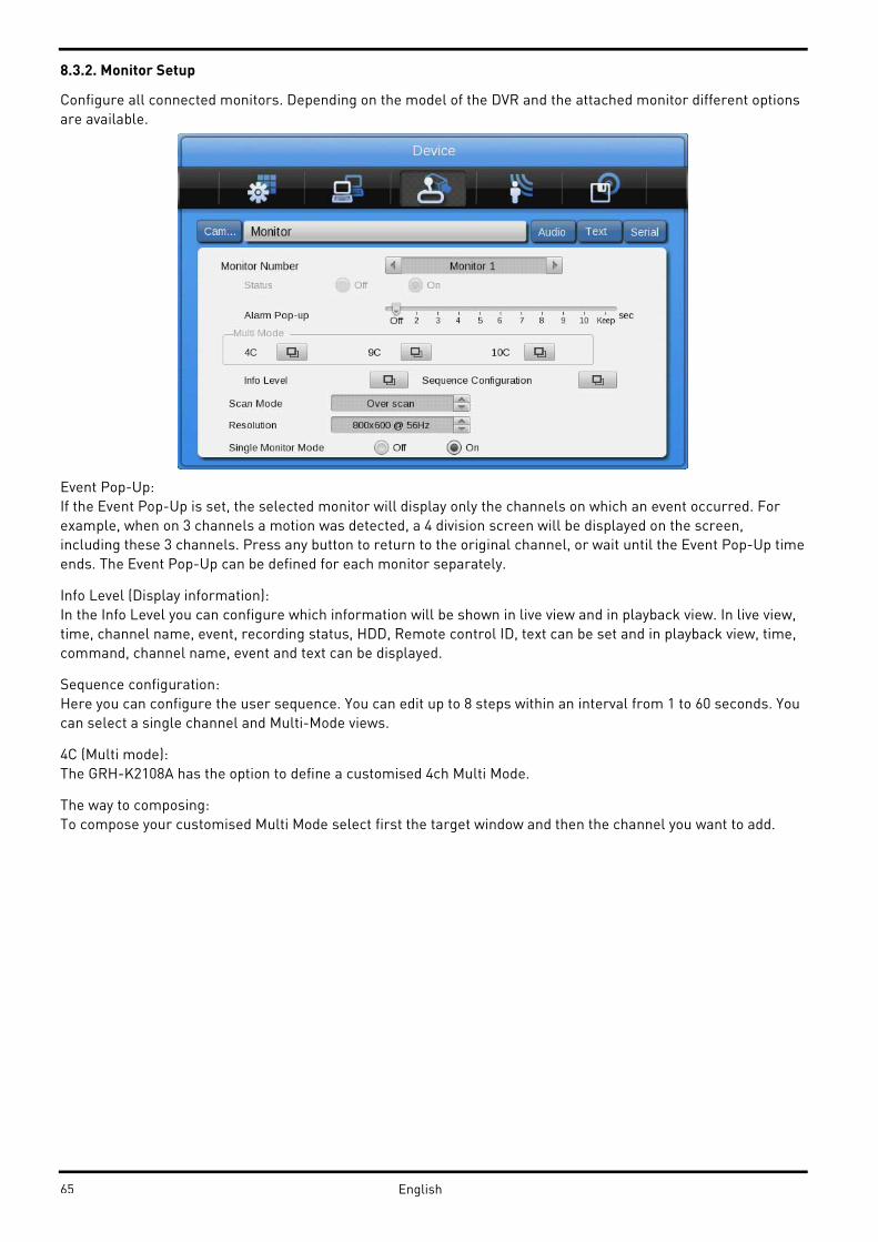
8.3.2. Monitor Setup
Configure all connected monitors. Depending on the model of the DVR and the attached monitor different options
are available.
Event Pop-Up:
If the Event Pop-Up is set, the selected monitor will display only the channels on which an event occurred. For
example, when on 3 channels a motion was detected, a 4 division screen will be displayed on the screen,
including these 3 channels. Press any button to return to the original channel, or wait until the Event Pop-Up time
ends. The Event Pop-Up can be defined for each monitor separately.
Info Level (Display information):
In the Info Level you can configure which information will be shown in live view and in playback view. In live view,
time, channel name, event, recording status, HDD, Remote control ID, text can be set and in playback view, time,
command, channel name, event and text can be displayed.
Sequence configuration:
Here you can configure the user sequence. You can edit up to 8 steps within an interval from 1 to 60 seconds. You
can select a single channel and Multi-Mode views.
4C (Multi mode):
The GRH-K2108A has the option to define a customised 4ch Multi Mode.
The way to composing:
To compose your customised Multi Mode select first the target window and then the channel you want to add.
65 English
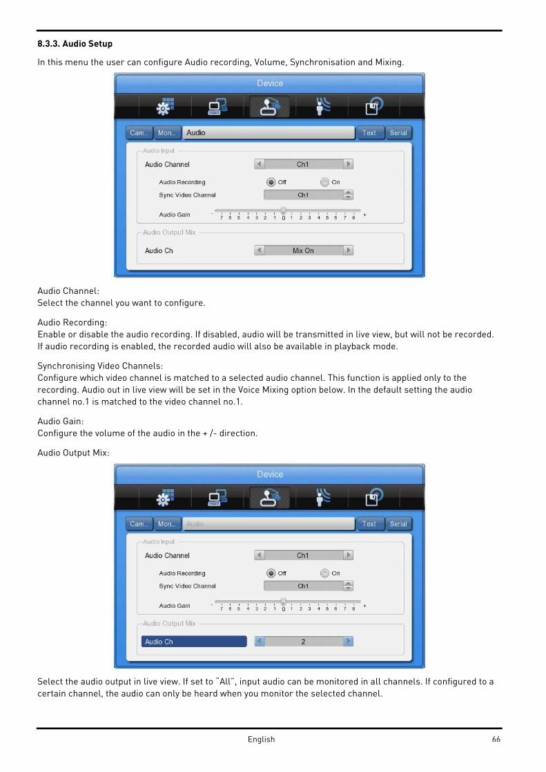
8.3.3. Audio Setup
In this menu the user can configure Audio recording, Volume, Synchronisation and Mixing.
Audio Channel:
Select the channel you want to configure.
Audio Recording:
Enable or disable the audio recording. If disabled, audio will be transmitted in live view, but will not be recorded.
If audio recording is enabled, the recorded audio will also be available in playback mode.
Synchronising Video Channels:
Configure which video channel is matched to a selected audio channel. This function is applied only to the
recording. Audio out in live view will be set in the Voice Mixing option below. In the default setting the audio
channel no.1 is matched to the video channel no.1.
Audio Gain:
Configure the volume of the audio in the + /- direction.
Audio Output Mix:
Select the audio output in live view. If set to “All”, input audio can be monitored in all channels. If configured to a
certain channel, the audio can only be heard when you monitor the selected channel.
66English
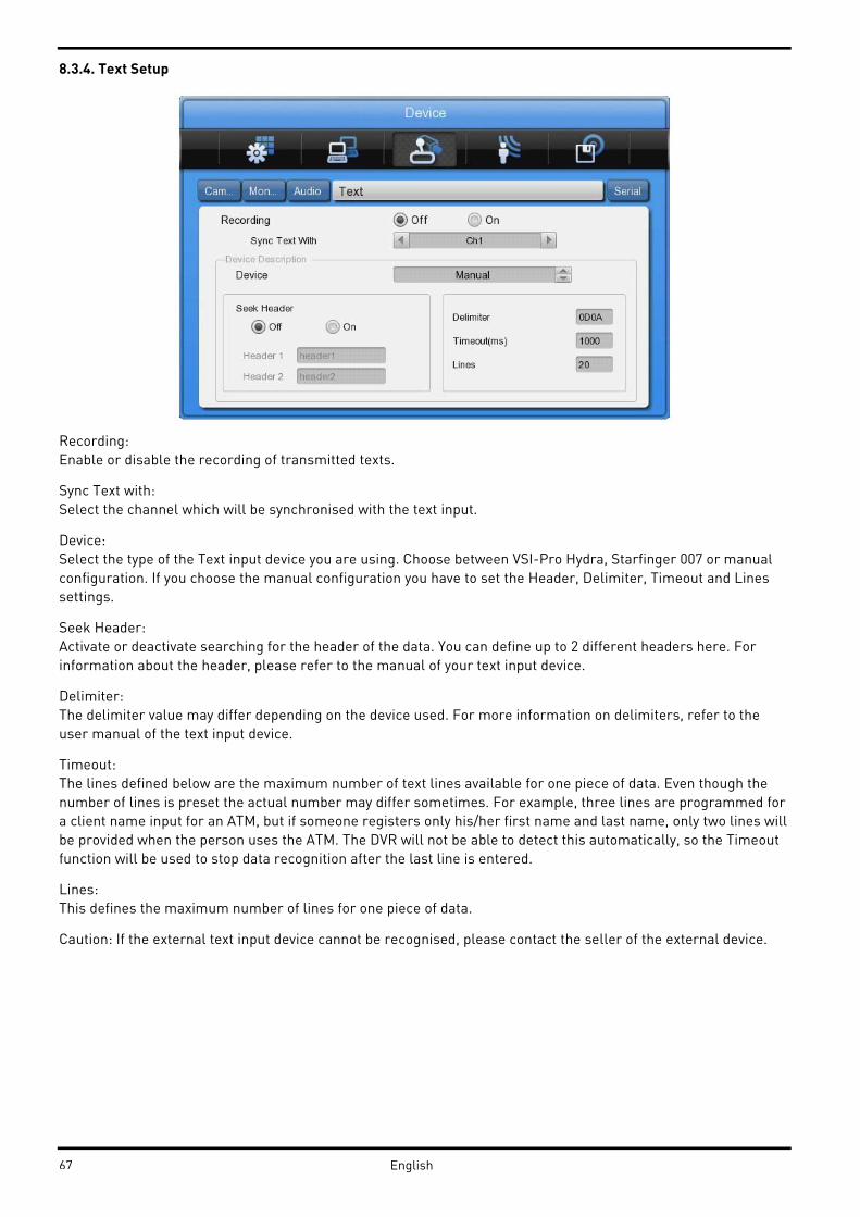
8.3.4. Text Setup
Recording:
Enable or disable the recording of transmitted texts.
Sync Text with:
Select the channel which will be synchronised with the text input.
Device:
Select the type of the Text input device you are using. Choose between VSI-Pro Hydra, Starfinger 007 or manual
configuration. If you choose the manual configuration you have to set the Header, Delimiter, Timeout and Lines
settings.
Seek Header:
Activate or deactivate searching for the header of the data. You can define up to 2 different headers here. For
information about the header, please refer to the manual of your text input device.
Delimiter:
The delimiter value may differ depending on the device used. For more information on delimiters, refer to the
user manual of the text input device.
Timeout:
The lines defined below are the maximum number of text lines available for one piece of data. Even though the
number of lines is preset the actual number may differ sometimes. For example, three lines are programmed for
a client name input for an ATM, but if someone registers only his/her first name and last name, only two lines will
be provided when the person uses the ATM. The DVR will not be able to detect this automatically, so the Timeout
function will be used to stop data recognition after the last line is entered.
Lines:
This defines the maximum number of lines for one piece of data.
Caution: If the external text input device cannot be recognised, please contact the seller of the external device.
67 English

8.3.5. Serial Setup
The DVR has 3 serial ports. One is a RS-232 serial connection and the other 2 ports are serial RS-485 connections.
Serial Port:
Select which serial port you want to configure.
Device:
Select the connected device and the protocol that it is using.
Interface:
Configure which interface the device is using.
COM1 is RS-232C; COM2 and COM3 are RS-485.
Baud rate/Parity Bit/Stop Bit/Data Bit:
Input a suitable value depending on the external device.
8.4. Event Setup
In this menu users can configure the handling of an event.
68English

8.4.1. Event Check
Enable or disable the event checking algorithms. You can set up a schedule for the event check if you want to
enable the event check only for a certain time frame. In the case of schedule mode, you can set up schedules for
different dates and times, as shown in the following screenshot.
Create a schedule:
The user can start a schedule event by clicking with the mouse or using the front panel direction and [Enter]
buttons to create schedule indexes. An active index (marked yellow) can be changed afterwards by changing the
program type and the time.
You can also copy an index to all other days by clicking on the [Daily] button. This will copy the yellow marked
index to the other days. Existing indexes on these days will not be deleted, but split.
To delete an index, select it by using the mouse or the direction keys and press the [Delete] button.
69 English
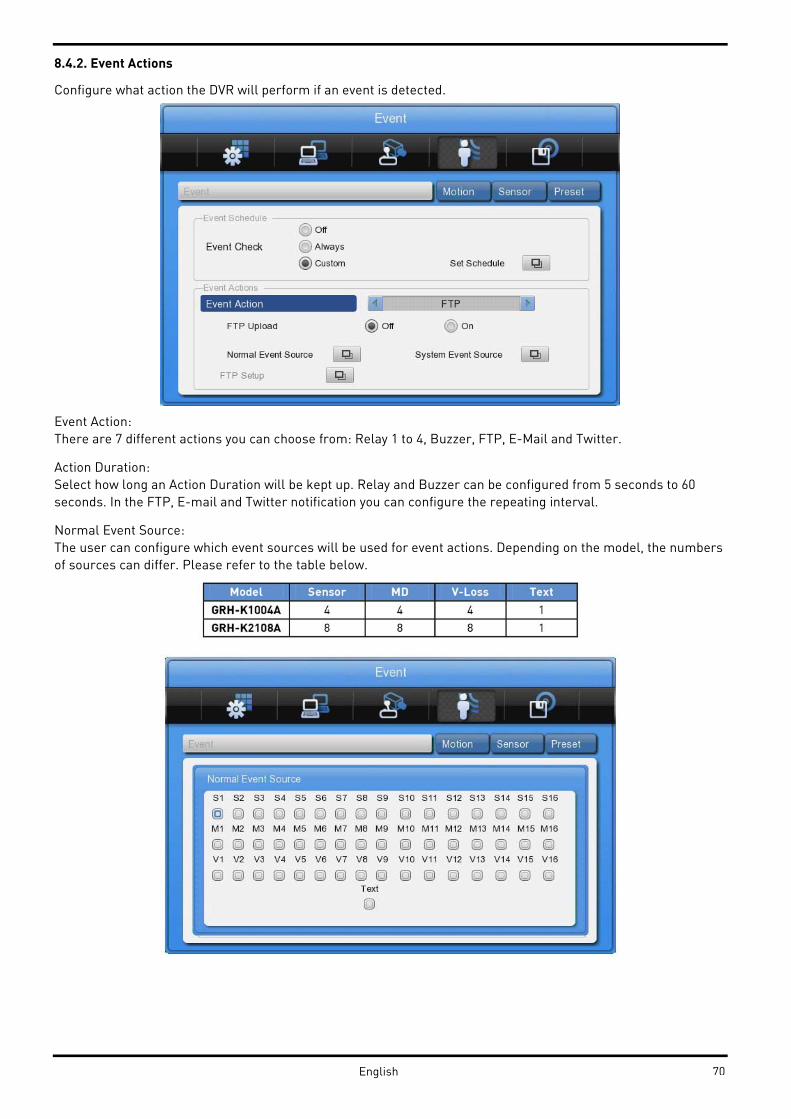
8.4.2. Event Actions
Configure what action the DVR will perform if an event is detected.
Event Action:
There are 7 different actions you can choose from: Relay 1 to 4, Buzzer, FTP, E-Mail and Twitter.
Action Duration:
Select how long an Action Duration will be kept up. Relay and Buzzer can be configured from 5 seconds to 60
seconds. In the FTP, E-mail and Twitter notification you can configure the repeating interval.
Normal Event Source:
The user can configure which event sources will be used for event actions. Depending on the model, the numbers
of sources can differ. Please refer to the table below.
70English

System Event source:
In the system event source menu you can configure which system events are used for event action (Bad block,
Disk full, Fan error, Authorisation failure, DDNS registration failure).
E-Mail:
Here you can set up the sender & receiver E-mail address.
E-mail address:
Input the E-mail address to get an event alarm to this E-Mail address.
Sender Address:
Not mandatory, but necessary if the receiver wants to know which DVR sent the event.
71 English
Authentification:
Please select here if your SMTP Server needs an authentification. You can also choose if your SMTP Server is
using a TLS encryption method.
SMTP Server: Enter your SMTP server address, provided by your email address provider.
User ID: Enter the username for your email address.
Password: Enter your email password.
SMTP Port: Enter the port your SMTP server is using. This information can also be obtained from your email
provider.
Including Picture:
In a general event, when sensor, MD, video signal loss events are generated, the event information and channel
information will be sent together with the E-mail. A system event just sends the system event information.
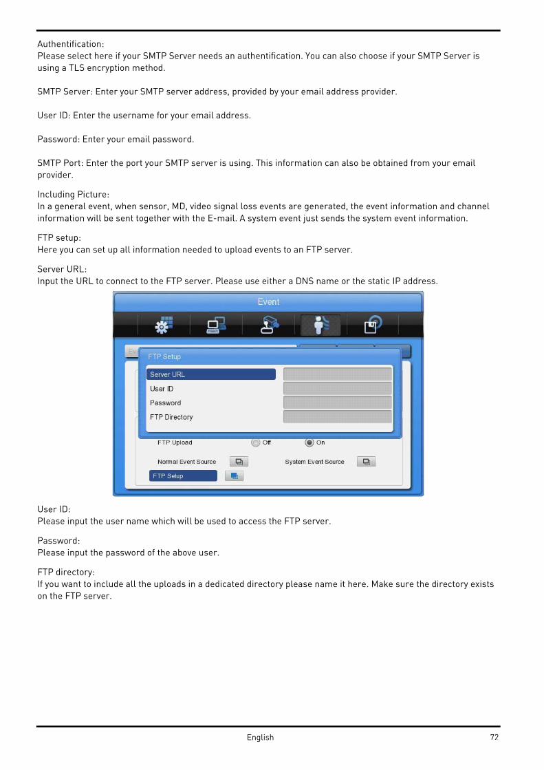
FTP setup:
Here you can set up all information needed to upload events to an FTP server.
Server URL:
Input the URL to connect to the FTP server. Please use either a DNS name or the static IP address.
User ID:
Please input the user name which will be used to access the FTP server.
Password:
Please input the password of the above user.
FTP directory:
If you want to include all the uploads in a dedicated directory please name it here. Make sure the directory exists
on the FTP server.
72English

Twitter setup:
1. Generate PIN
This will generate a link to the Twitter website, where you can allow the access of the DVR to your account.
NOTE: If you have a valid e-mail account already set up in your DVR, you can send this link directly to your e-mail
address, which will make the setup easier. Otherwise you will need to write down the address by hand and put it
manually in your web browser.
2. Open the Link in a Web browser.
3. Put in your access data in the web browser and allow the DVR to access your Twitter account.
4. Twitter will provide a PIN number that you can put into the field in the DVR.
5. Now the connection should be established automatically.
NOTE: The DVR cannot change your privacy settings in your Twitter account. If you do not want to share the
events with other people, make sure your Twitter account is set to private mode. Check the Twitter website for
details how to privatise your account.
8.4.3. Motion Detection
Channel:
Select if you want to configure all channels or only a dedicated one.
73 English

Sensitivity:
The sensitivity of the motion detection can be configured from min. 1 to max. 10, whereas 1 means less sensitive
and 10 means very sensitive.
Area:
Select the detection area. The user can either select the whole area or can define a customised user area.
User Area:
A user area can only be defined for a single channel. The video is divided into 22x15 grids. After pushing the user
area button, the configuration window for the detection area will appear.
Select an area with the direction keys and press [Enter] or click the mouse to select or deselect an area which is
used for motion detection. The first selected field will define the start and the second one will draw a rectangle
within these 2 fields. Combine several rectangles to optimise the Motion detection area. Press the [ESC] button or
click the right mouse button to apply your settings and go back to the previous menu.
8.4.4. Sensor
This menu is to set up the existing sensor input and the type of the sensor.
GRH-K2108A has 8 inputs and GRH-K1004A has 4 inputs.
The sensors can be set either to Normal Open (N.O.) or to Normal Close (N.C.).
74English

8.4.5. Preset
Configure which preset is loaded for PTZ cameras when an event is detected. You can select between sensor
events, motion detection and text synchronisation. You can configure up to 16 presets per camera. The preset
position can be configured in the PTZ single channel view.
8.5. Recording Setup
There are 4 modes for recording – schedule recording, manual recording, event recording and continuous
recording
Schedule Recording records according to a configured schedule. Manual Recording records only after pushing
the [REC] button, continuous recording will record all the time and Event Recording records when events are
detected.
8.5.1. Program Setup
Here you can setup the recording resolution, frame rate and quality for every channel for normal recording and
for event recording.
Program:
There are 9 programs from A to I composing the recording quality and resolution per channel.
For a detailed explanation please refer to the program configuration below.
75 English

CH (Channel):
Displays the channel number.
R (Resolution):
There are 2 resolutions: 720p & 1020p.
F (FPS):
FPS means frame per second. The user can select a frame rate from 1 to 30 fps. The max. frame rate can differ
according to the configuration.
Q (Quality):
There are 5 recording qualities: Q5 / Q4 / Q3 / Q2 / Q1. The recommended quality for event recording is Q3. Q1 has
a low quality which needs less storage space and Q5 is a higher quality which needs more storage space.
NOTE: If you disable a channel or lower its resolution or its frame rate the unused bandwidth can be used for
other channels to increase their frame rate or resolution.
The relation between general recording and event recording:
When an event is triggered, the DVR records with the event recording settings. The recording performance of the
DVR differs for every model.
8.5.2. Manual / Continuous / Schedule Recording Setup
In the submenu “Record” you can select the recording behaviour. Select between Manual & Event, Schedule &
Event recording or Continuous & Event recording.
Manual & Event Recording:
If set to Manual & Event, the DVR will record when pressing the [REC] button. It will stop recording when you
press [REC] again.
You can also set which program is used for manual recordings.
76English

Continuous & Event Recording:
If the DVR is set to Continuous & Event the DVR will record all the time. If an event occurs the recording setting
will be changed from continuous to event settings.
Schedule & Event Recording:
The DVR can record automatically, depending on the programmed schedule. Set the recording mode to Schedule
& Event and configure the days and time in the schedule submenu.
77 English
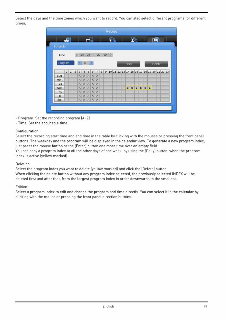
Select the days and the time zones which you want to record. You can also select different programs for different
times.
- Program: Set the recording program (A~Z)
- Time: Set the applicable time
Configuration:
Select the recording start time and end time in the table by clicking with the mousee or pressing the front panel
buttons. The weekday and the program will be displayed in the calendar view. To generate a new program index,
just press the mouse button or the [Enter] button one more time over an empty field.
You can copy a program index to all the other days of one week, by using the [Daily] button, when the program
index is active (yellow marked).
Deletion:
Select the program index you want to delete (yellow marked) and click the [Delete] button.
When clicking the delete button without any program index selected, the previously selected INDEX will be
deleted first and after that, from the largest program index in order downwards to the smallest.
Edition:
Select a program index to edit and change the program and time directly. You can select it in the calendar by
clicking with the mouse or pressing the front panel direction buttons.
78English

9. GRUNDIG Web Viewer
The GRUNDIG WebViewer is a Web application program to access the DVR over an Ethernet or Internet
connection. You can monitor the live view or access the recorded data with this program.
The GRUNDIG WebViewer is divided into the Login page, the Monitor page, where you can monitor the live video,
and the Playback page to access recorded videos.
9.1. System Requirements
9.2. Login
After inputting the IP address of the DVR, the GRUNDIG WebViewer Login page will be displayed in the browser
window.
Input the User ID and Password and click ‘LOGIN’ to access.
If the user/administrator did not change the password in the Control Center, the ID and the Password will be:
ID: admin / user1 / user2 / … / user10
Password: 1234 / 1111 / 2222 / …/ 0000
79 English

9.3. User Setup
To access the GRUNDIG WebViewer, user authority and password can be changed in the DVR or in the Control
Center configuration (see the following images).
The basic admin password is “1234” and the user password is “1111“ for User 1, “2222” for User 2 etc. The
password for User 10 is “0000”. A valid password can have up to 8 digits.
This authority configuration is almost the same in the DVR as in the Control Center. But the authorisation of quick
recording and the coverting of dedicated channels for a user are only possible in the Control Center.
80English

9.4. Available Browser
The GRUNDIG WebViewer is optimised for the Windows Internet Explorer 6.0 or higher. But GRUNDIG also
supplies a Java based access to the DVR that can be used with other browsers like Mozilla Firefox, Apple Safari,
Google Chrome or the Opera browser.
WebViewer Installer:
The Login page provides a manual installation program for the WebViewer.
A PC that accesses the WebViewer for the first time will install an ActiveX certificate to use the WebViewer’s
functions. If this installation fails, the installation program can be downloaded from the Login Page and installed
manually.
Caution:
When installing the WebViewer Installer, all programs related to the Control Center have to be closed. Otherwise
the installation might fail.
9.5. Monitor
When successfully authorised with User ID & Password input at the Login page, you will be directed to the
Monitor page. On the Monitor page you can view live videos of cameras connected to DVR, or you can control a
PTZ camera, Relays, and use the Microphone function according to user’s authorisation.
9.5.1. Screen division and changing video position
When accessing the Monitor page for the first time, 9 divisions, 16 divisions or 32 divisions (according to the
number of channels of the DVR) are displayed.
81 English

You can change to 1, 4, 9, 13, 16, 25 or 36 divisions by clicking on the number on top of the page.
Also, you can change to 1-channel mode by clicking on any of the channel images.
Double-click on one of the channels to switch to 1-channel mode.
After entering 1-channel mode, a double-click on the screen will return to the previous division of channels.
On the division screen, you can change the screen location.
If you want to move channel 3 to the position of channel 6, drag the 3ch image and drop it on the 6ch location.
Channel 6 will automatically move to the former position of channel 3.
82English

9.5.2. Playback on Standard monitor (16 / 9 / 4 division)
Move to the playback function by clicking on the image above.
9.5.3. Channel On/Off
You can select which channels are played by clicking the On/Off button of the Channel located on the left hand
side of the page.
9.5.4. Sensor Indication
The icons indicate whether a sensor event occurred in the system.
When a sensor is activated, the relevant sensor icon will change to red colour.
9.5.5. Relay operation
You can turn on or off the relays of the DVR within the WebViewer. Click the number button to activate the relay
and the icon will change from blue to orange.
If you define a time for the relay in the Control Center, the Control Center will be turned off automatically after
this configuration.
Activating relays is only possible when the user posseses the authorisation. Refer to the chapter “User Authority”
in this manual for the setup of user authority for relays.
9.5.6. Using a microphone
You can enable or disable the use of a microphone within the GRUNDIG WebViewer. The default setting is Off. If a
microphone is activated, the colour of the corresponding icon will change from blue to red.
83 English

9.5.7. Event Data
The event log is displayed at the bottom of the monitoring page and shows all the event information stored on the
DVR.
9.5.8. Relay operation
The indicated data is listed as follows:
[Table / Event Icon]
9.5.9. Video Recording & Safe Saving
Video Recording:
During monitoring, the GRUNDIG WebViewer can record up to 10 minutes of video by clicking the Quick Recording
button (the red dot in the top panel). During Quick Recording, the recording time is shown on the video.
During video recording, click the Quick Recording button to stop recording and a dialogue box will be opened to
store the recorded files.
Saved recording files are saved in “*.re4” file format. The .re4 file can be played back by the GRUNDIG Control
Center Playback software or the GRUNDIG Mini Player software.
Screenshots:
You can make a screenshot of the video by clicking on the right mouse button in the selected channel and by
choosing the “Save As” option. The picture can be stored in .jpg, .bmo or .eye file format.
84English
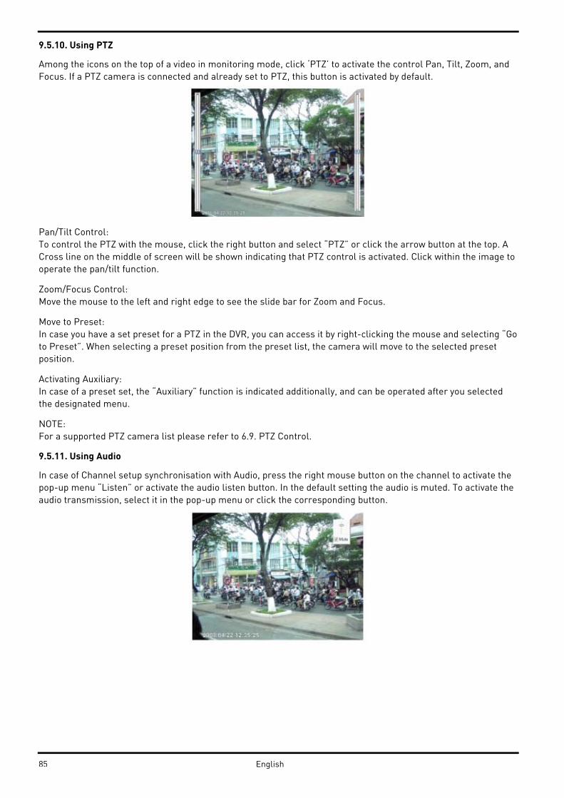
9.5.10. Using PTZ
Among the icons on the top of a video in monitoring mode, click ‘PTZ’ to activate the control Pan, Tilt, Zoom, and
Focus. If a PTZ camera is connected and already set to PTZ, this button is activated by default.
Pan/Tilt Control:
To control the PTZ with the mouse, click the right button and select “PTZ” or click the arrow button at the top. A
Cross line on the middle of screen will be shown indicating that PTZ control is activated. Click within the image to
operate the pan/tilt function.
Zoom/Focus Control:
Move the mouse to the left and right edge to see the slide bar for Zoom and Focus.
Move to Preset:
In case you have a set preset for a PTZ in the DVR, you can access it by right-clicking the mouse and selecting “Go
to Preset”. When selecting a preset position from the preset list, the camera will move to the selected preset
position.
Activating Auxiliary:
In case of a preset set, the “Auxiliary” function is indicated additionally, and can be operated after you selected
the designated menu.
NOTE:
For a supported PTZ camera list please refer to 6.9. PTZ Control.
9.5.11. Using Audio
In case of Channel setup synchronisation with Audio, press the right mouse button on the channel to activate the
pop-up menu “Listen” or activate the audio listen button. In the default setting the audio is muted. To activate the
audio transmission, select it in the pop-up menu or click the corresponding button.
85 English

9.5.12. Closing Video Channel
You can disable and enable channels by clicking on the corresponding button at the top of the screen.
9.6. Playback
If you have the user rights to play back video, you can access the Playback screen when pressing the “Go” button
on the Monitor screen of the GRUNDIG WebViewer.
In the Playback screen you can monitor up to 16 video streams simultaneously and search through a calendar to
see recorded video from that date. You can make backups of the videos and save images in .bmp format or print
them directly.
9.6.1. Video Division & Changing Channel
The Playback supports 1, 4, 9 and 16 divisional screens. You can select the number of divisions using the menu on
the top of the page as shown in the picture above.
If the screen shows 4 divisions CH1~CH4, you can change to CH5~CH8 using the ‘Next’ button. Press the ‘Prev’
button to call for the previous channel group CH1~CH4.
The analogue 32ch DVR can call the channels 17-32 using the group moving button as follows:
86English

9.6.2. Image recording
You can save a playback image as ‘.bmp’ picture file.
Select the channel with the mouse and click the ‘Save’ button.
A Save Image dialogue box appears and you can input a memo text or select if the channel name, date and event
data should be written unto the file.
Press ‘OK’ to open the dialogue box for the saving location, then you can save it as a ‘.bmp’ file.
9.6.3. Printing
Select the channel you want to print, and click the ‘Print’ button.
A window pops up to input a memo text. Click the ‘OK’ button to print the image on the connected printer. The
Printout will include the ‘Printing Date’, ‘Channel name’, ‘Recording Date’, ‘Event’ and the ‘Memo’ text.
87 English

9.6.4. Backup
You can choose between .re4 (multi-channel) or .avi (single-channel) backup. Select the time, date and channel
you want to back up und choose a location to save the file to.
If you want to secure the video file you can input a password which has to be verified.
9.6.5. Web Monitor
Click on the ‘Go’ button at the top of the page to return to the Web Monitor page.
9.6.6. Channel On/Off
This function is similar to the Channel On/Off function of the Web Monitor.
9.6.7. Saving Time & Checking Rec. Capacity
This field indicates the total capacity of the HDD and also displays the Starting date & Last date of the recorded
video on the DVR. The image shows the percentage (%) of the DVR’s HDD capacity.
88English

9.6.8. Searching in the Calendar
When a video was recorded on a special date, that day will be coloured in black. When a day is coloured in grey,
this means that there was no video recorded on this date. Select the year, month, day and time to play back the
video of that date.
When clicking on the ‘Go to’ button, you get access to the 24 hours of that date.
9.6.9. Functions at the bottom of monitor
(1) Indicates the playback range of the recorded image.
(2) Press the -> <- buttons to jump to the time area of an earlier or later time.
(3) From left to right: ‘One frame back’, ‘Play backward’, ‘Stop’, ‘Play’, ‘One frame forward’.
(4) Here you can set the playback speed. After clicking the button, it can set the playback speed to ‘0.5x, 1x, 2x,
4x, 16x, 32x, 64x, and All’.
(5) Here you can set the time area. After clicking the button, select the time area out of ‘10min, 30min, 1hour,
3hour, 6hour, 12hour, 24hour’.
(6) Here you can select if you want to use DirectX or not. If checking/activating DirectX mode, the WebViewer will
use the graphic card of the PC to display the video. This will reduce the CPU workload.
(7) Here you can set if audio should be played or not, and you can change the volume.
89 English
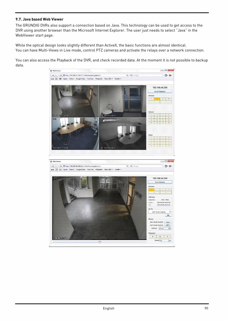
9.7. Java based Web Viewer
The GRUNDIG DVRs also support a connection based on Java. This technology can be used to get access to the
DVR using another browser than the Microsoft Internet Explorer. The user just needs to select “Java” in the
WebViewer start page.
While the optical design looks slightly different than ActiveX, the basic functions are almost identical.
You can have Multi-Views in Live mode, control PTZ cameras and activate the relays over a network connection.
You can also access the Playback of the DVR, and check recorded data. At the moment it is not possible to backup
data.
90English
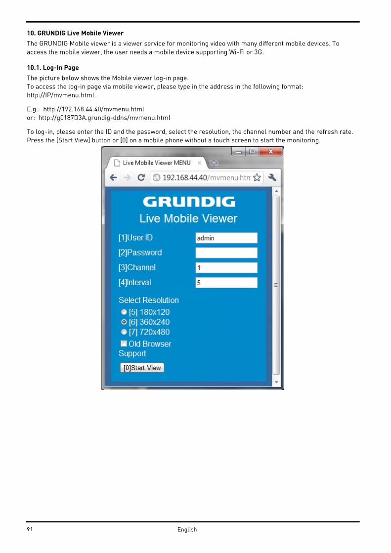
10. GRUNDIG Live Mobile Viewer
The GRUNDIG Mobile viewer is a viewer service for monitoring video with many different mobile devices. To
access the mobile viewer, the user needs a mobile device supporting Wi-Fi or 3G.
10.1. Log-In Page
The picture below shows the Mobile viewer log-in page.
To access the log-in page via mobile viewer, please type in the address in the following format:
http://IP/mvmenu.html.
E.g.: http://192.168.44.40/mvmenu.html
or: http://g0187D3A.grundig-ddns/mvmenu.html
To log-in, please enter the ID and the password, select the resolution, the channel number and the refresh rate.
Press the [Start View] button or [0] on a mobile phone without a touch screen to start the monitoring.
91 English

10.2. Monitoring Page
The monitoring page shows the selected channel video and some functions you can use, right below the video
display. The functions can be activated by pressing the buttons (touchscreen devices) or pressing the
corresponding number on your phone keypad.
For the functions, please refer to the description below.
(0) MENU : Move back to Login page
(1) CH- : Move to previous channel
(2) UP : If the channel is PTZ you can move the camera up
(3) WIDE : If the channel is PTZ you can zoom out
(4) <- : If the channel is PTZ you can move the camera to the left
(6) -> : If the channel is PTZ you can move the camera to the right
(7) CH+ : Move to next channel
(8) DN : If the channel is PTZ you can move the camera down
(9) TELE : If the channel is PTZ you can zoom in
92English
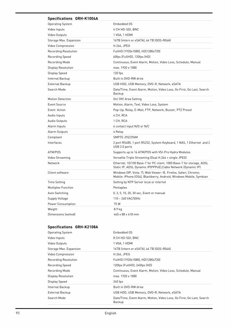
Specifications GRH-K1004A
Operating System Embedded OS
Video Inputs 4 CH HD-SDI, BNC
Video Outputs 1 VGA, 1 HDMI
Storage Max. Expansion 16TB (intern or eSATA), 64 TB (GDS-R04A)
Video Compression H.264, JPEG
Recording Resolution FullHD (1920x1080), HD(1280x720)
Recording Speed 60fps (FullHD), 120fps (HD)
Recording Mode Continuous, Event Alarm, Motion, Video Loss, Schedule, Manual
Display Resolution max. 1920 x 1080
Display Speed 120 fps
Internal Backup Built in DVD-RW drive
External Backup USB HDD, USB Memory, DVD-R, Network, eSATA
Search Mode Date/Time, Event Alarm, Motion, Video Loss, Go First, Go Last, Search
Backup
Motion Detection On/ Off/ Area Setting
Event Source Motion, Alarm, Text, Video Loss, System
Event Action Pop-Up, Relay, E-Mail, FTP, Network, Buzzer, PTZ Preset
Audio Inputs 4 CH, RCA
Audio Outputs 1 CH, RCA
Alarm Inputs 4 contact input N/O or N/C
Alarm Outputs 4 Relay
Compliant SMPTE-292/296M
Interfaces 2 port RS485, 1 port RS232, System Keyboard, 1 NAS, 1 Ethernet and 2
USB 2.0 ports
ATM/POS Supports up to 16 ATM/POS with VSI-Pro Hydra Modules
Video Streaming Versatile Triple Streaming (Dual H.264 + single JPEG)
Network Ethernet, 10/100 Base-T for PC client, 1000 Base-T for storage, ADSL
Static IP, ADSL Dynamic IP(PPPoE),Cable Network (Dynamic IP)
Client software Windows (XP, Vista, 7), Web Viewer: IE, Firefox, Safari, Chrome;
Mobile: iPhone (OS4), Blackberry, Android, Windows Mobile, Symbian
Time Setting Setting by NTP Server local or internet
Multiplex Function Pentaplex
Auto Switching 0, 3, 5, 10, 20, 30 sec, Event or manual
Supply Voltage 110 ~ 240 VAC/50Hz
75 WPower Consumption
8.9 kgWeight
445 x 88 x 418 mmDimensions (wxhxd)
Specifications GRH-K2108A
Operating System Embedded OS
Video Inputs 8 CH HD-SDI, BNC
Video Outputs 1 VGA, 1 HDMI
Storage Max. Expansion 16TB (intern or eSATA), 64 TB (GDS-R04A)
Video Compression H.264, JPEG
Recording Resolution FullHD (1920x1080), HD(1280x720)
Recording Speed 120fps (FullHD), 240fps (HD)
Recording Mode Continuous, Event Alarm, Motion, Video Loss, Schedule, Manual
Display Resolution max. 1920 x 1080
Display Speed 240 fps
Internal Backup Built in DVD-RW drive
External Backup USB HDD, USB Memory, DVD-R, Network, eSATA
Search Mode Date/Time, Event Alarm, Motion, Video Loss, Go First, Go Last, Search
Backup
93 English

Motion Detection On/ Off/ Area Setting
Event Source Motion, Alarm, Text, Video Loss, System
Event Action Pop-Up, Relay, E-Mail, FTP, Network, Buzzer, PTZ Preset
Audio Inputs 4 CH, RCA
Audio Outputs 1 CH, RCA
Alarm Inputs 8 contact input N/O or N/C
Alarm Outputs 4 Relay
Compliant SMPTE-292/296M
Interfaces 2 port RS485, 1 port RS232, System Keyboard, 1 NAS, 1 Ethernet and 2
USB 2.0 ports
ATM/POS Supports up to 16 ATM/POS with VSI-Pro Hydra Modules
Video Streaming Versatile Triple Streaming (Dual H.264 + single JPEG)
Network Ethernet, 10/100 Base-T for PC client, 1000 Base-T for storage, ADSL
Static IP, ADSL Dynamic IP(PPPoE),Cable Network (Dynamic IP)
Client software Windows (XP, Vista, 7), Web Viewer: IE, Firefox, Safari, Chrome;
Mobile: iPhone (OS4), Blackberry, Android, Windows Mobile, Symbian
Time Setting Setting by NTP Server local or internet
Multiplex Function Pentaplex
Auto Switching 0, 3, 5, 10, 20, 30 sec, Event or manual
Supply Voltage 110 ~ 240 VAC/50Hz
75 WPower Consumption
8.9 kgWeight
445 x 88 x 418 mmDimensions (wxhxd)
94English

EC Declaration of Conformity
GRH-K1004A 4 Channel H.264 HD-SDI Recorder with DVD-
RW Drive
GRH-K2108A 8 Channel H.264 HD-SDI Recorder with DVD-
RW Drive
It is hereby certified that the products meet the standards in
the following relevant provisions:
EC EMC Directive 2004/108/EC
Low Voltage Directive 2006/95/EC
Applied harmonised standards and technical specifications:
EN 60950-1 Part 1
EN 55022 Class A (2006 + A1: 2007)
EN 61000-3-2 (2006)
EN 61000-3-3 (2008)
EN 61000-3-3 (1995 + A1: 2001 + A2: 2005)
EN 50130-4
Ludwig Bergschneider
CEO
Remscheid, 05.12.2011
ASP AGLüttringhauser Str. 9
42897 Remscheid
Germany
95 English