owner's manual crnftsmrn · dental starting when setting up, transport-ing, adjusting or...
TRANSCRIPT

Owner's Manual
CRnFTSMRN°
REAR TINE TILLER WITHCOUNTER ROTATING TINES5.0 HP17 Inch Tine Width
Model No.917.294251
• Espahol, p. 21
This product has a low emission engine which operates
[_ differently from previously built engines. Before start theyouengine, read and understand this Owner's Manual,
IMPORTANT:
Read and follow all SafetyRules and Instructions before
operating this equipment.
Sears, Roebuck and Co., Hoffman Estates, IL 60179 U.S.A.
Visit our Craftsman website:www.sears.com/craftsman

Safety Rules .......................................... 2Warranty ................................................ 2Product Specifications ......................... 4Assembly/Pre-Operation ....................... 6Operation ............................................... 8Maintenance ........................................ 13
Service and Adjustments ..................... 15Storage ................................................ 18Troubleshooting ................................... 19Illustrated Parts List ............................. 40Sears Service ........................ Back Cover
LIMITED TWO YEAR WARRANTY ON CRAFTSMAN TILLER
For two (2) years from date of purchase, when this Craftsman Tiller is maintained,lubricated, and tuned up according to the operating and maintenance instructions in theowner's manual, Sears will repair free of charge any defect in material or workmanship.
This Warranty does not cover:• Expendable items which become worn during normal use, such as tines, spark plugs,
air cleaners and belts.• Repairs necessary because of operator abuse or negligence, including bent crank-
shafts and the failure to maintain the equipment according to the instructions con-tained in the owner's manual.
• If this Craftsman Tiller is used for commercial or rental purposes, this Warranty appliesfor only thirty (30) days from the date of purchase.
Warranty service is available by returning the craftsman power mower to the nearestsears service center/department in the united states. This warranty applies only whilethis product is in use in the united states.
This Warranty gives you specific legal rights, and you may also have other rights whichvary from state to state.
SEARS, ROEBUCK AND CO., D/817WA, HOFFMAN ESTATES, IL 60179 U.S.A.
IMPORTANT: This cutting machine is capable of amputating hands and feet and throw-ing objects. Failure to observe the following safety instructions could result in seriousinjury or death.
TRAINING
• Read the Owner's Manual carefully. Bethoroughly familiar with the controls andthe proper use of the equipment. Knowhow to stop the unit and disengage thecontrols quickly.
• Never allow children to operate theequipment. Never allow adults to op-erate the equipment without properinstruction.
• Keep the area of operation clear of allpersons, particularly small children, andpets.
PREPARATION
• Thoroughly inspect the area where theequipment is to be used and remove allforeign objects.
• Disengage all clutches and shift intoneutral before starting the engine (mo-tor).
• Do not operate the equipment withoutwearing adequate outer garments. Wearfootwear that will improve footing onslippery surfaces.
• Handle fuel with care; it is highly flam-mable.
• Use an approved fuel container.• Never add fuel to a running engine or
hot engine.• Fill fuel tank outdoors with extreme care.
Never fill fuel tank indoors.• Replace gasoline cap securely and
clean up spilled fuel before restarting.

• Useextensioncordsand receptaclesas specifiedby the manufacturerfor allunitswith electricdrive motorsor elec-tric starting motors.
• Neverattemptto makeanyadjustmentswhile the engine (motor)is running(ex-ceptwhere specificallyrecommendedby manufacturer).
OPERATION
• Do not put hands or feet near or underrotating parts.
• Exercise extreme caution when operat-ing on or crossing gravel drives, walks,or roads. Stay alert for hidden hazardsor traffic. Do not carry passengers.
• After striking a foreign object, stop theengine (motor), remove the wire fromthe spark plug, thoroughly inspect thetiller for any damage, and repair thedamage before restarting and operatingthe tiller.
• Exercise caution to avoid slipping or fall-ing.
• If the unit should start to vibrate ab-normally, stop the engine (motor) andcheck immediately for the cause. Vibra-tion is generally a warning of trouble.
• Stop the engine (motor) when leavingthe operating position.
• Take all possible precautions when leav-ing the machine unattended. Disengagethe tines, shift into neutral, and stop theengine.
• Before cleaning, repairing, or inspecting,shut off the engine and make certain allmoving parts have stopped. Disconnectthe spark plug wire, and keep the wireaway from the plug to prevent accidentalstarting. Disconnect the cord on electricmotors.
• Do not run the engine indoors; exhaustfumes are dangerous.
• Never operate the tiller without properguards, plates, or other safety protectivedevices in place.
• Keep children and pets away.• Do not overload the machine capacity
by attempting to till too deep at too fasta rate.
• Never operate the machine at highspeeds on slippery surfaces. Look be-hind and use care when backing.
• Never allow bystanders near the unit.• Use only attachments and accessories
approved by the manufacturer of thetiller.
• Never operate the tiller without good vis-ibility or light.
• Be careful when tilling in hard ground.The tines may catch in the ground andpropel the tiller forward. If this occurs,let go of the handlebars and do notrestrain the machine.
MAINTENANCE AND STORAGE
• Keep machine, attachments, and ac-cessories in safe working condition.
• Check shear pins, engine mountingbolts, and other bolts at frequent inter-vals for proper tightness to be sure theequipment is in safe working condition.
• Never store the machine with fuel in the
fuel tank inside a building where ignitionsources are present, such as hot waterand space heaters, clothes dryers, andthe like. Allow the engine to cool beforestoring in any enclosure.
• Always refer to the operator's guideinstructions for important details if thetiller is to be stored for an extended
period._Look for this symbol to point outimportant safety precautions. It meansCAUTION!!! BECOME ALERT!!! YOURSAFETY IS INVOLVED.
_CAUTION: Always disconnect sparkplug wire and place wire where it cannotcontact spark plug in order to prevent acci-dental starting when setting up, transport-ing, adjusting or making repairs._WARNING: Engine exhaust, some of itsconstituents, and certain vehicle compo-nents contain or emit chemicals known tothe State of California to cause cancer andbirth defects or other reproductive harm.
3

PRODUCT SPECIFICATIONS
Gasoline 2 QuartsCapacity: Unleaded Regular
Oil (API-SF-SJ): SAE 30(Capacity: 20 oz.) (Above 40°F)
SAE5W-30/10W-30
Spark Plug : NGK(Gap: .030") BPR6ES
CONGRATULATIONS on your purchaseof a Sears Tiller. It has been designed,engineered and manufactured to give youthe best possible dependability and per-formance.
Should you experience any problems youcannot easily remedy, please contact aSears or other qualified Service Center.We have competent, well-trained techni-cians and the proper tools to service orrepair this unit.Please read and retain this manual. The
instructions will enable you to assembleand maintain your tiller properly. Alwaysobserve the "SAFETY RULES".Your new tiller has been assembled at the
factory with exception of those parts leftunassembled for shipping purposes. Toensure safe and proper operation of yourtiller all parts and hardware you assemblemust be tightened securely. Use the cor-rect tools as necessary to insure propertightness.
CUSTOMER RESPONSIBILITIES
• Read and observe the safety rules.• Follow a regular schedule in main-
taining, caring for and using your tiller.• Follow the instructions under the "Main-
tenance" and "Storage" sections of thisOwner's Manual.
_WARNING: This unit is equipped withan internal combustion engine and shouldnot be used on or near any unimprovedforest-covered, brush-covered or grasscovered land unless the engine's exhaustsystem is equipped with a spark arrestermeeting applicable local or state laws (ifany). If a spark arrester is used, it shouldbe maintained in effective working orderby the operator.
In the state of California the above is
required by law (Section 4442 of theCalifornia Public Resources Code). Otherstates may have similar laws. Federallaws apply on federal lands. A spark ar-rester for the muffler is available throughyour nearest Sears service center (SeeREPAIR PARTS section of this manual).
REPAIR PROTECTIONAGREEMENTS
Congratulations on making a smart pur-chase. Your new Craftsman® product isdesigned and manufactured for years ofdependable operation. But like all products,it may require repair from time to time. That'swhen having a Repair Protection Agreementcan save you money and aggravation.Purchase a Repair Protection Agreementnow and protect yourself from unexpectedhassle and expense.Here's what's included in the Agreement:• Expert service by our 12,000 profe-
sional repair specialists.• Unlimited service and no charge for
parts and labor on all covered repairs.• Product replacement if your covered
product can't be fixed.• Discount of 10% from regular price of
service and service-related parts notcovered by the agreement; also, 10%off regular price of preventive mainte-nance check.
• Fast help by phone- phone supportfrom a Sears technician on productsrequiring in-home repair, plus conve-nient repair scheduling.
Once you purchase the Agreement, asimple phone call is all that it takes for youto schedule service. You can call anytimeday or night, or schedule a service ap-pointment online.Sears has over 12,000 professional repairspecialists, who have access to over 4.5million quality parts and accessories.That's the kind of professionalism you cancount on to help prolong the life of yournew purchase for years to come. Purchaseyour Repair Protection Agreement today!Some limitations and exclusions apply.For prices and additional informationcall 1-800-827-6655.
SEARS INSTALLATION SERVICE
For Sears professional installation of homeappliances, garage door openers, waterheaters, and other major home items, inthe U.S.A. call 1-800-4-MY-HOME®
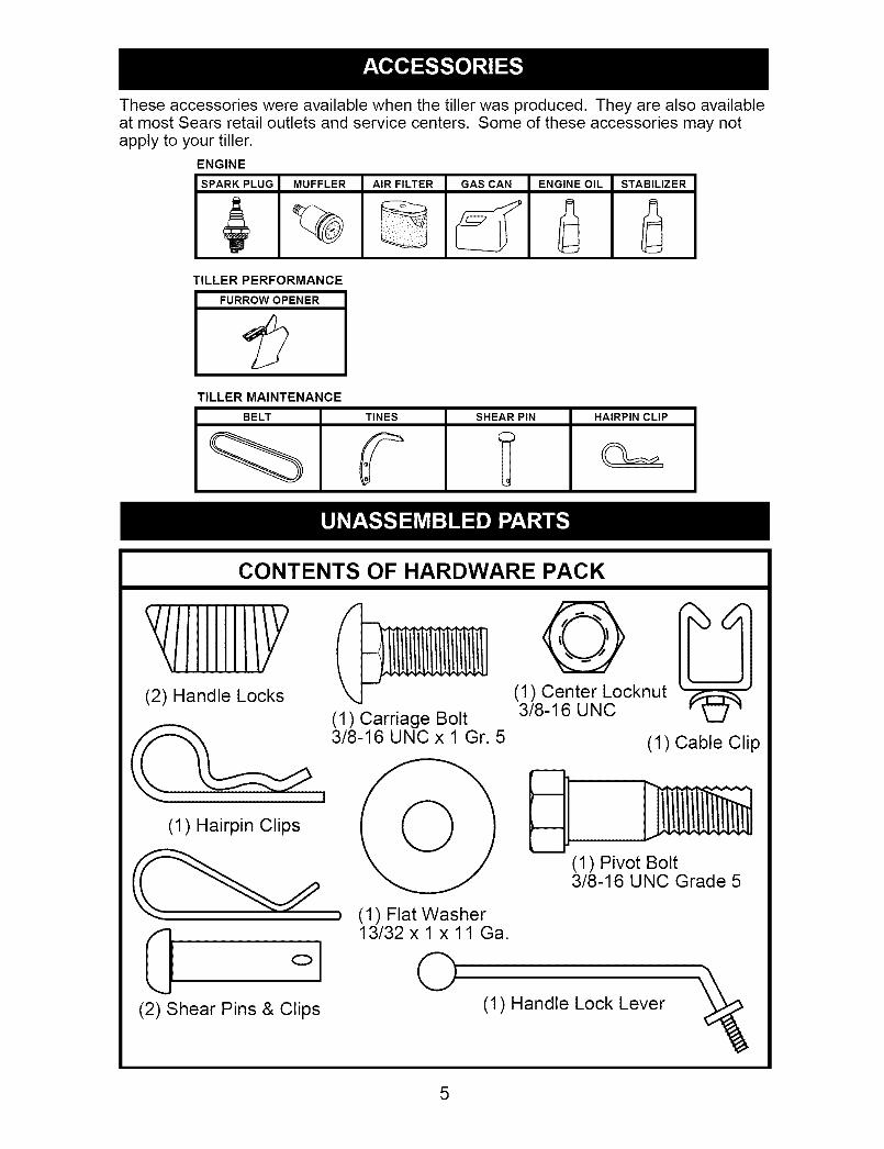
Theseaccessorieswere availablewhenthe tiller was produced. Theyare also availableat most Sears retail outletsand service centers. Someof theseaccessoriesmay notapply to your tiller.
ENGINE
SPARK PLUG MUFFLER AIR FILTER GAS CAN ENGINE OIL STABILIZER
TILLER PERFORMANCE
FURROW OPENER
TILLER MAINTENANCE
BELT TINES SHEAR PIN HAIRPIN CLIP
CONTENTS OF HARDWARE PACK
YIIIIIII/Y(2) Handle Locks
(1) Carriage Bolt3/8-16 UNC x 1 Gr. 5
(1) Hairpin Clips
0 ol(2) Shear Pins & Clips
(1) Flat Washer13/32 x 1 x 11 Ga.
0
0(1) Center Locknut3/8-16 UNC
(1) Cable Clip
(1) Pivot Bolt3/8-16 UNC Grade 5
(1) Handle Lock Lever
5

Your new tiller has been assembled at the factory with the exception of those parts leftunassembled for shipping purposes. To ensure safe and proper operation of your tillerall parts and hardware you assemble must be tightened securely. Use the correct toolsas necessary to insure proper tightness.
TOOLS REQUIRED FORASSEMBLY
A socket wrench set will make assemblyeasier. Standard wrench sizes are listed.(1) Utility knife(1) Wire cutter(1) Tire pressure gauge(1) Screwdriver(1) Pair of pliers(1) 9/16" wrench
4. Cut down right hand front and righthand rear corners of carton, lay sidecarton wall down.
5. Remove packing material from handleassembly.
6. Separate shift rod from handle as-sembly.
Shift Rod
OPERATOR'S POSITION
When right or left hand is mentioned inthis manual, it means when you are in theoperating position (standing behind tillerhandles).
FRONT
LEFT RIGHT
OPERATOR'SPOSITION
UNPACKING CARTON
_LCAUTION: Be careful of exposed sta-ples when handling or disposing of carton-ing material.IMPORTANT: When unpacking andassembling tiller, be careful of exposedstaples when handling or disposing ofcartoning material.1. While holding handle assembly, cut cable
ties securing handle assembly to topframe. Let handle assembly rest on tiller.
2. Remove top frame of carton.3. Slowly ease handle assembly up and
place on top of carton.
Assembly
INSTALL HANDLE
1. Insert one handle lock (with teeth fac-ing outward) in gearcase notch. (Applygrease on smooth side of handle lockto aid in keeping lock in place untilhandle assembly is lowered into po-sition.)
VIEWED FROM R.H. SIDE OF TILLER
___Ge andle Assembly
arcase Notch
_._ ._ /Htndle L°ck
2. Grasp handle assembly. Hold in "up"position. Be sure handle lock remainsin gearcase notch. Slide handle as-sembly into position.
3. Rotate handle assembly down. Insertrear carriage bolt first, with head ofbolt on L.H. side of tiller and loosely as-semble Iocknut.

Handle Column
"UP" Position
Loosen Handle Lockf_Lever to Move
4. Insert pivot bolt in front part of plateand tighten.
5. Cut down remaining corners of cartonand lay panels flat.
6. Lower the handle assembly. Tightennut on carriage bolt so handle moveswith some resistance. This will allowfor easier adjustment.
7. Place flat washer on threaded end ofhandle lock lever.
8. Insert handle lock lever through handlebase and gearcase. Screw in handlelock lever just enough to hold lever inplace.
9. Insert second handle lock (with teethinward) in the slot of the handle base(just inside of washer).
10. Raise handle assembly to highestposition and securely tighten handlelock lever by rotating clockwise. Leav-ing handle assembly in highest positionwill make it easier to connect shift rod.
Flat Washer Handle LockHandle Lever
Gearcase
Slot
Rear CartridgeBolt
Handle Base_ocknut J'_LPiv°t Bolt
INSERT CABLE CLIP
• Insert plastic cable clip into hole on theback of handle column. Push cables
into clip.
Cables
Cable Clip
handles 14
CONNECT SHIFT ROD
1. Insert end of shift rod farthest frombend into hole of shift lever indicator.
2. Insert hairpin clip through hole of shiftrod to secure with bend of clip on rightside.
0-"_- Attach this End To shift
Lever Indicator
Shift Rod
Shift LeverHairpin Clip Indicator
Shift Rod
7
REMOVE TILLER FROM CRATE
1. Adjust handle assemby to lowestposition. Be sure lock lever is tightenedsecurely.
2. Make sure shift lever indicator is in "N"
(neutral) position.3. Tilt tiller forward by lifting handle. Sep-
arate cardboard cover from levelingshield.
4. Rotate tiller handle to the right and pulltiller out of carton.
CHECKTIRE PRESSURE
The tires on your unit were overinflated atthe factory for shipping purposes. Correctand equal tire pressure is important forbest tilling performance.• Reduce tire pressure to 20 PSI.
HANDLE HEIGHT
• Handle height may be adjusted to bet-ter suit operator. (See "TO ADJUSTHANDLE HEIGHT" in the Service andAdjustments section of this manual).

Thesesymbols mayappearon yourTiller or in literaturesuppliedwith the product.Learnand understandtheir meaning.KNOWYOURTILLER
READ THIS OWNER'S MANUAL AND SAFETY RULES BEFORE OPERATING YOURTILLER.
Compare the illustrations with your tiller to familiarize yourself with the location ofvarious controls and adjustments. Save this manual for future reference.
TILLING FORWARD NEUTRAL REVERSE CAUTION ENGINE ENGINE FAST SLOW CHOKE FUEL OIL STOP V
OR WARNING ON OFF
Shift Lever
Drive Control BarShift Lever Indicator
Depth Stake
Leveling Shield
Outer Side Shield
RecoilStarterHandle
MEETS ANSI SAFETY REQUIREMENTS
Our tillers conform to the safety standards of the American National Standards Institute.
DRIVE CONTROL BAR - Used to engagetines.
DEPTH STAKE - Controls depth at whichtiller will dig.OUTER SIDE SHIELD - Adjustable toprotect small plants from being buried.LEVELING SHIELD - Levels tilled soil.
SHIFT LEVER - Used to shift transmission
gears.SHIFT LEVER INDICATOR - Shows
which gear the transmission is in.RECOIL STARTER HANDLE - Used to
start the engine.

Theoperationof any tiller can result in foreignobjects throwninto the eyes,which can result in severeeyedamage.Alwayswearsafety glassesor eyeshieldsbeforestartingyour tiller andwhile tilling.We recommenda wide vi-sion safetymaskoverspectaclesor standardsafetyglasses.
HOW TO USE YOUR TILLERKnow how to operate all controls beforeadding fuel and oil or attempting to startengine.
STOPPINGTINES AND DRIVE
1. Release drive control bar to stop move-ment.
2. Move shift lever to "N" (neutral) po-sition.
ENGINE
• Move throttle control to "STOP" position.If equipped with stop switch, moveswitch to "STOP" position.
NOTE: Never use choke to stop engine.
Drive Control Bar
"ENGAGED" Position Shift Lever
Drive Control Bar"DISENGAGED"Position
TINE OPERATION - WITH WHEEL
DRIVE
• Always release drive control bar beforemoving shift lever into another position.
• Tine movement is achieved by mov-ing shift lever to (_,) till position andengaging drive control bar.
FORWARD -WHEELS ONLY/TINESSTOPPED• Release drive control bar and move shift
lever indicator to "F" (forward) position.Engage drive control bar and tiller willmove forward.
REVERSE - WHEELS ONLY/TINESSTOPPED
1. DO NOT STAND DIRECTLY BEHINDTILLER.
2. Release the drive control bar.
3. Move throttle control to "SLOW" po-sition.
4. Move shift lever indicator to "R" (re-verse) position.
5. Hold drive control bar against thehandle to start tiller movement.
HARD TO SHIFT GEARS
• Briefly engage drive control bar and re-lease or rock tiller forward and backward
until are able to shift gears.
DEPTH STAKE
The depth stake can be raised or loweredto allow you more versatile tilling and cul-tivating, or to more easily transport yourtiller.
Shallowest Tilling(Cultivating)
Deeptest Tilling_
Depth Stake -------
"-" Transport Position
TILLING
1. Release depth stake pin. Pull thedepth stake up for increased tillingdepth. Place depth stake pin in hole ofdepth stake to lock in position.
2. Place shift lever indicator in till position.3. Hold the drive control bar against the
handle to start tilling movement. Tinesand wheels will both turn.
4. Move throttle control to "FAST" positionfor deep tilling. To cultivate, throttlecontrol can be set at any desiredspeed, depending on how fast or slowyou wish to cultivate.
IMPORTANT: Always release drive controlbar before moving shift lever into anotherposition.
Depth Stake Pin"RELEASED" Position
)5_
Nut"a"
Outer SideShield
"Locked"Position
9

TURNING1. Release the drive control bar.2. Move throttle control to "SLOW" posi-
tion.3. Place shift lever indicator in "F" (for-
ward) position. Tines will not turn.4. Lift handle to raise tines out of ground.5. Swing the handle in the opposite
direction you wish to turn, being carefulto keep feet and legs away from tines.
6. When you have completed your turn-around, release the drive control barand lower handle. Place shift lever in(till) position and move throttle controlto desired speed. To begin tilling, holddrive control bar against the handle.
OUTER SIDE SHIELDS
The back edges of the outer side shieldsare slotted so that the shields can beraised for deep tilling and lowered forshallow tilling to protect small plants frombeing buried.1. Loosen nut "A" in slot and nut"B".2. Move shield to desired position (both
sides).3. Retighten nuts.
TO TRANSPORT
_I, CAUTION: Before lifting or transporting,allow tiller engine and muffler to cool. Dis-connect spark plug wire. Drain gasolinefrom fuel tank.AROUND THE YARD
1. Release the depth stake pin. Movethe depth stake down to the top holefor transporting the tiller. Place depthstake pin in hole of depth stake to lockin position. This prevents tines fromscuffing the ground.
2. Place shift lever indicator in "F" (for-ward) position for transporting.
3. Hold the drive control bar against thehandle to start tiller movement. Tineswill not turn.
4. Move throttle control to desired speed.AROUND TOWN
1. Disconnect spark plug wire.2. Drain fuel tank.3. Transport in upright position to prevent
oil leakage.
BEFORE STARTING ENGINE
IMPORTANT: Be very careful not to allowdirt to enter the engine when checking oradding oil or fuel. Use clean oil and fueland store in approved, clean, coveredcontainers, use clean fill funnels.
CHECK ENGINE OIL LEVEL
The engine in your unit has been shipped,from the factory, already filled with SAE 30summer weight oil.1. With engine level, clean area around
oil filler plug and remove plug.2. Engine oil should be to point of over-
flowing when engine is level.• For approximate capacity see "PROD-
UCT SPECIFICATIONS" on page 3 ofthis manual. All oil must meet A.P.I.Service Classification SF-SJ.
• For cold weather operation you shouldchange oil for easier starting (See oilviscosity chart in the Maintenance sec-tion of this manual).
• To change engine oil, see the Mainte-nance section in this manual.
Oil Fill
Filler Plug
Drain Plug
ADD GASOLINE
• Fill fuel tank to bottom of filler neck. Donot overfill. Use fresh, clean, regularunleaded gasoline with a minimum of87 octane. (Use of leaded gasoline willincrease carbon and lead oxide depos-its and reduce valve life). Do not mix oilwith gasoline. Purchase fuel in quan-tities that can be used within 30 days toassure fuel freshness.
_CAUTION: Fill to within 1/2 inch of topof fuel tank to prevent spills and to allowfor fuel expansion. If gasoline is acci-dentally spilled, move machine away fromarea of spill. Avoid creating any source ofignition until gasoline vapors have disap-peared.Wipe off any spilled oil or fuel. Do notstore, spill or use gasoline near an openflame.
IMPORTANT: When operating in temper-atures below32°F(0°C), use fresh, cleanwinter grade gasoline to help insure goodcold weather starting.
10

CAUTION: Alcohol blended fuels (calledgasohol or using ethanol or methanol) canattract moisture which leads to separa-tion and formation of acids during storage.Acidic gas can damage the fuel systemof an engine while in storage. To avoidengine problems, the fuel system shouldbe emptied before storage of 30 daysor longer. Drain the gas tank, start theengine and let it run until the fuel linesand carburetor are empty. Use fresh fuelnext season. See Storage Instructions foradditional information. Never use engineor carburetor cleaner products in the fueltank or permanent damage may occur.
TO START ENGINE
_CAUTION: Keep drive control bar in"DISENGAGED" position when startingengine.When starting engine for the first time or ifengine has run out of fuel, it will take extrapulls of the recoil starter to move fuel fromthe tank to the engine.1. Make sure spark plug wire is properly
connected.
2. Move shift lever indicator to "N" (neu-tral) position.
3. Place throttle control in "FAST" posi-tion.
5. Move choke control to choke position.5. Grasp recoil starter handle with one
hand and grasp tiller handle with otherhand. Pull rope out slowly until enginereaches start of compression cycle(rope will pull slightly harder at thispoint).
6. Pull recoil starter handle quickly. Donot let starter handle snap backagainst starter.
NOTE: If engine fires but does not start,move choke control to half choke posi-tion. Pull recoil starter handle until enginestarts.7. When engine starts, slowly move
choke control to "RUN" position asengine warms up.
NOTE: A warm engine requires lesschoking to start.8. Move throttle control to desired running
position.9. Allow engine to warm up for a few
minutes before engaging tines.NOTE: If at a high altitude (3000 feet) orin cold temperatures (below 32°F), thecarburetor fuel mixture may need to beadjusted for best engine performance.
See "TO ADJUST CARBURETOR" in the
Service and Adjustments section of thismanual.
NOTE: If engine does not start, see trou-
11
bleshooting points.
Choke Controli- _ _._
-,_:_,,i¸ •
Recoil Starter _Handle _ _._
_:,_ parkPlug
Throttle,_Y,_ Control
',_ 2_"__
TILLING HINTS
_;_,CAUTION: Until you are accustomedto handling your tiller, start actual fielduse with throttle in slow position (mid-waybetween "FAST" and "IDLE").• Tilling is digging into, turning over, and
breaking up packed soil before plant-ing. Loose, unpacked soil helps rootgrowth. Best tilling depth is 4" to 6". Atiller will also clear the soil of unwanted
vegetation. The decomposition of thisvegetable matter enriches the soil.Depending on the climate (rainfall andwind), it may be advisable to till the soilat the end of the growing season tofurther condition the soil.
• Soil conditions are important for propertilling. Tines will not readily penetratedry, hard soil which may contribute toexcessive bounce and difficult handlingof your tiller. Hard soil should be mois-tened before tilling; however, extremelywet soil will "ball-up" or clump during till-ing. Wait until the soil is less wet in orderto achieve the best results. When tillingin the fall, remove vines and long grassto prevent them from wrapping aroundthe tine shaft and slowing your tillingoperation.
• You will find tilling much easier if youleave a row untilled between passes.Then go back between tilled rows.Thereare two reasons for doing this. First,wide turns are much easier to negoti-ate than about-faces. Second, the tillerwon't be pulling itself, and you, towardthe row next to it.
• Do not lean on handle. This takes
weight off the wheels and reducestraction. To get through a really toughsection of sod or hard ground, applyupward pressure on handle or lower thedepth stake.

CULTIVATINGCultivatingis destroyingthe weeds be-tween rows to preventthem from robbingnourishmentand moisturefrom the plants.At the same time, breakingup the upperlayerof soil crustwill help retain moisturein the soil.Bestdiggingdepth is 1" to 3"(2.5-7.5cm). Lowerthe outer side shieldsto protectsmall plantsfrom beingburied.• Cultivateup and downthe rowsat a
speedwhichwill allow tines to uprootweeds and leavethe ground in roughcondition,promotingno further growthof weeds and grass.
O O Ol wm
O O Ol
O O Oil!O O Ol
ADJUST WHEELS FOR
CULTIVATING
1. Place blocks under right hand side oftiller and remove hairpin clip and clevispin from right hand wheel.
2. Move wheel outward approximately 1inch until hole in inner wheel hub lines
up with inner hole in axle.3. Replace clevis pin and hairpin clip on
inside of wheel and remove blocks.
4. Repeat preceding steps on left handside.
NOTE: In extremely rough conditions andwhile cultivating, the wheels should bemoved outward on the axle for increased
stability.
OUTER VIEW OF TIRE
_ levis
Pin
in Cllip
INNER VIEW OF TIRE
ClevisPin
TINE SHEAR PINS
The tine assemblies on your tiller aresecured to the tine shaft with shear pins(See "TINE REPLACEMENT" in theService and Adjustments section of thismanual).If the tiller is unusually overloaded orjammed, the shear pins are designed tobreak before internal damage occurs tothe transmission.• If shear pin(s) break, replace only with
those shown in the Repair Parts sectionof this manual.
HairpinCli
tire 2
12

MAINTENANCESCHEDULE
FILL IN DATESAS YOU COMPLETEREGULAR SERVICE
Check Engine Oil Level
Change Engine Oil
Oil Pivot Points
Inspect Spark Arrester / Muffler V'
Inspect Air Screen I_
Clean or Replace Air Cleaner Cartridge 1_2
Clean Engine Cylinder Fins V'
Replace Spark Plug V'
_ _" & _" SERVtCE DATES4Yi-W-X /
v" v"
v1112€
RH Gear Case Grease Fitting (1oz.) If
1 - Change more often when operating under a heavy load or in high ambient temperatures2 - Service more often when operating in dirty or dusty conditions
GENERAL RECOMMENDATIONS
The warranty on this tiller does not coveritems that have been subjected to op-erator abuse or negligence. To receive fullvalue from the warranty, the operator mustmaintain tiller as instructed in this manual.
Some adjustments will need to be madeperiodically to properly maintain your tiller.At least once a season, check to see ifyou should make any of the adjustmentsdescribed in the Service and Adjustmentssection of this manual.
• At least once a year you should replacethe spark plug, clean or replace air filter,and check tines and belts for wear. A
new spark plug and clean air filter as-sure proper air-fuel mixture and helpyour engine run better and last longer.
BEFORE EACH USE
1. Check engine oil level.2. Check tine operation.3. Check for loose fasteners.
LUBRICATION
Keep unit well lubricated (See "LUBRI-CATION CHART").
LUBRICATION CHART
@Engine @RH Gear CaseGrease Fitting
ODepth Stake Pin
(])IdlerBracket OWheel Hub
(])LevelingShieldHinges
O SAE 30 OR 10W-30 Motor Oil@ Refer to Maintenance "ENGINE" section@ EP#1 Grease
13

AI_CAUTION: Disconnect spark plugwire before performing any maintenance(except carburetor adjustment) to preventaccidental starting of engine.Prevent fires! Keep the engine free ofgrass, leaves, spilled oil, or fuel. Removefuel from tank before tipping unit for main-tenance. Clean muffler area of all grass,dirt, and debris.Do not touch hot muffler or cylinder fins ascontact may cause burns.
ENGINE
LUBRICATION
Use only high quality detergent oil ratedwith API service classification SF-SJ. Se-
lect the oil's SAE viscosity grade accord-ing to your expected temperature.
SAE
lo_ -qO I
TI::Mp -zo o zo 40 so S0 100"F/bill/
I t I I I I I I-30 -20 -10 0 10 20 30 40"C
AMBIENT TEMPERATURE
NOTE: Although multi-viscosity oils(5W-30, 10W-30, etc.)improve starting incold weather, they will result in increasedoil consumption when used above 40°F(4°C). Check your engine oil level morefrequently to avoid possible engine dam-age from running low on oil.Change the oil after every 25 hours ofoperation or at least once a year if the tilleris not used for 25 hours in one year.Check the crankcase oil level beforestarting the engine and after each five (5)hours of continuous use. Add SAE 30 mo-
tor oil or equivalent. Tighten oil filler plugsecurely each time you check the oil level.
TO CHANGE ENGINE OIL
Determine temperature range expectedbefore oil change. All oil must meet APIservice classification SF-SJ.• Be sure tiller is on level surface.• Oil will drain more freely when warm.• Use a funnel to prevent oil spill on tiller,
and catch oil in a suitable container.1. Remove drain plug.2. Tip tiller forward to drain oil.3. After oil has drained completely,
replace oil drain plug and tighten se-curely.
4. Remove oil filler plug. Be careful not toallow dirt to enter the engine.
5. Refill engine with oil. See "CHECKENGINE OIL LEVEL" in the Operationsection of this manual.
Oil drainPlu{
Oil Level
._/ Oil Fill Plug
AIR FILTER
Your engine will not run properly and maybe damaged by using a dirty air filter.Replace the air filter every 100 hours ofoperation or every season, whichever oc-curs first. Service air cleaner more oftenunder dusty conditions.
TO CLEAN AIR FILTER
1. Remove cover.
2. Carefully remove cartridge.3. Clean by gently tapping on a flat sur-
face. If very dirty, replace cartridge._:i,CAUTION: Petroleum solvents, such askerosene, are not to be used to clean car-tridge. They may cause deterioration of thecartridge. Do not oil cartridge. Do not usepressurized air to clean or dry cartridge.4. Install cartridge, then replace cover.
Latch Tabs
Filter
Tabs Filter
MUFFLER
Do not operate tiller without muffler. Donot tamper with exhaust system. Dam-aged mufflers or spark arresters couldcreate a fire hazard. Inspect periodicallyand replace if necessary. If your engine isequipped with a spark arrester screen as-sembly, remove every 50 hours for clean-ing and inspection. Replace if damaged.
14

SPARK PLUG
Replace spark plugs at the beginning ofeach tilling season or after every 50 hoursof use, whichever comes first. Spark plugtype and gap setting is shown in "PROD-UCT SPECIFICATIONS" on page 4 of thismanual.TRANSMISSION
Once a season, lubricate the right handgear case grease fitting with 1 oz. of EP#1 grease.
CLEANING
Do not clean your tiller when the engineand transmission are hot. We do not rec-
ommend using pressurized water (gardenhose, etc.) to clean your unit unless thegasket area around the transmission andthe engine muffler, air filter and carburetorare covered to keep water out. Water inengine will shorten the useful life of yourtiller.
• Clean engine, wheels, finish, etc. of allforeign matter.
• Keep finished surfaces and wheels freeof all gasoline, oil, etc.
• Protect painted surfaces with auto-motive type wax.
_CAUTION: Disconnect spark plug wirefrom spark plug and place wire where itcannot come into contact with plug.
TILLER
TO ADJUST HANDLE HEIGHT
Select handle height best suited for yourtilling conditions. Handle height will bedifferent when tiller digs into soil.1. First loosen handle lock lever.
2. Handle can be positioned at differentsettings between "HIGH" and "LOW"positions.
3. Retighten handle lock lever securelyafter adjusting.
Handle (High) Position
Handle Lock Lever
Handle (Low)Position
TIRE CARE
_CAUTION: When mounting tires, unlessbeads are seated, overinflation can causean explosion.• Maintain 20 pounds of tire pressure. If
tire pressures are not equal, tiller willpull to one side.
• Keep tires free of gasoline or oil whichcan damage rubber.
TO REMOVE WHEEL
1. Place blocks under transmission to
keep tiller from tipping.2. Remove hairpin clip and clevis pin from
wheel.3. Remove wheel and tire.
4. Repair tire and reassemble.
Clevis Pin
Hairpin Cliptire 3
15

TO REMOVE BELT GUARD
NOTE: For ease of removal, remove hair-pin clip and clevis pin from left wheel. Pullwheel out from tiller about 1 inch.
1. Remove two (2) screws from side ofbelt guard.
2. Remove hex nut and washer from
bottom of belt guard (located behindwheel).
3. Pull belt guard out and away from unit.4. Replace belt guard by reversing above
procedure.
GuardHexNut andWasher(LocatedBehindTire)
Screws
Hairpin Clip and Clevis Pin
TO REPLACE GROUND DRIVE BELT
1. Remove belt guard as described in "TOREMOVE BELT GUARD".
Engine Pulley\
2. Remove old belt by slipping off enginepulley first then remove from trans-mission pulley.
3. Place new belt in groove of trans-mission pulley and into engine pulley.BELT MUST BE IN GROOVE ON TOPOF IDLER PULLEY. NOTE POSITIONOF BELT TO GUIDES.
4. Check belt adjustment as describedbelow.
5. Replace belt guard.6. Reposition wheel and replace clevis
pin and hairpin clip.
GROUND DRIVE BELT ADJUSTMENT
For proper belt tension, the extensionspring should have about 5/8 inch stretchwhen drive control bar is in "ENGAGED"
position. This tension can be attained asfollows:1. Loosen cable clip screw securing the
drive control cable.2. Slide cable forward for less tension and
rearward for more tension until about5/8 inch stretch is obtained while the
drive control bar is engaged.3. Tighten cable clip screw securely.
Clip Screw
Drive Control Cable
Idler PulleyExtension S
Transmission Pulley
More Tension
TINE REPLACEMENT
_L,CAUTION: Tines are sharp. Weargloves or other protection when handlingtines.A badly worn tine causes your tiller towork harder and dig more shallow. Mostimportant, worn tines cannot chop andshred organic matter as effectively norbury it as deeply as good tines. A tine thisworn needs to be replaced.
New TineTine
16

• To maintain the superb tilling perfor-mance of this machine the tines should
be checked for sharpness, wear, andbending, particularly the tines whichare next to the transmission. If the gapbetween the tines exceeds 3-1/2 inches
they should be replaced or straightenedas necessary.
• New tines should be assembled. Sharp-ened tine edges will rotate rear
Tine
3-1/2" Max =--i_i
/
....,S :9-Fine
Counter TineRotation
Hairpin Clip
Hairpin Clip
Sharp Edge
J
Sharp Edge
Shear Pin Sharp Edges
Shear Pin
tine 13
ENGINE
Maintenance, repair, or replacement ofthe emission control devices and systems,which are being done at the customers ex-pense, may be performed by any non-roadengine repair establishment or individual.Warranty repairs must be performed by anauthorized engine manufacturer's serviceoutlet.TO ADJUST CARBURETOR
The carburetor has been preset at thefactory and adjustment should not benecessary. However, engine performancecan be affected by differences in fuel, tem-perature, altitude or load. If the carburetordoes need adjustment, contact your near-est Sears or other qualified service center.
IMPORTANT: Never tamper with theengine governor, which is factory setfor proper engine speed. Overspeedingthe engine above the factory high speedsetting can be dangerous. If you thinkthe engine-governed high speed needsadjusting, contact your nearest Sears orother qualified service center which hasthe proper equipment and experience tomake any necessary adjustments.
17

Immediately prepare your tiller for storageat the end of the season or if the unit will
not be used for 30 days or more._I, CAUTION: Never store the tiller with
gasoline in the tank inside a buildingwhere fumes may reach an open flameor spark. Allow the engine to cool beforestoring in any enclosure.
TILLER
1. Clean entire tiller (See "CLEANING" inthe Maintenance section of this man-
ual).2. Inspect and replace belts, if necessary
(See belt replacement instructions inthe Service and Adjustments section ofthis manual).
3. Lubricate as shown in the Maintenancesection of this manual.
4. Be sure that all nuts, bolts and screwsare securely fastened. Inspect movingparts for damage, breakage and wear.Replace if necessary.
5. Touch up all rusted or chipped paintsurfaces; sand lightly before painting.
ENGINE
FUEL SYSTEM
IMPORTANT: It is important to preventgum deposits from forming in essentialfuel system parts such as the carburetor,fuel filter, fuel hose, or tank during storage.Also, alcohol blended fuels (called gasoholor using ethanol or methanol) can attractmoisture which leads to separation andformation of acids during storage. Acidicgas can damage the fuel system of anengine while in storage.• Empty the fuel tank by starting the en-
gine and letting it run until the fuel linesand carburetor are empty.
• Never use engine or carburetor cleanerproducts in the fuel tank or permanentdamage may occur.
• Use fresh fuel next season.
NOTE: Fuel stabilizer is an acceptablealternative in minimizing the formation offuel gum deposits during storage. Addstabilizer to gasoline in fuel tank or stor-age container. Always follow the mix ratiofound on stabilizer container. Run engineat least 10 minutes after adding stabilizerto allow the stabilizer to reach the carbu-
retor. Do not empty the gas tank andcarburetor if using fuel stabilizer.ENGINE OIL
Drain oil (with engine warm) and replacewith clean oil. (See "ENGINE" in the Main-tenance section of this manual).CYLINDER
1. Remove spark plug.2. Pour 1 ounce (29 ml) of oil through
spark plug hole into cylinder.3. Pull starter handle slowly several times
to distribute oil.
4. Replace with new spark plug.
OTHER
• Do not store gasoline from one seasonto another.
• Replace your gasoline can if your canstarts to rust. Rust and/or dirt in yourgasoline will cause problems.
• If possible, store your unit indoors andcover it to give protection from dust anddirt.
• Cover your unit with a suitable protectivecover that does not retain moisture. Donot use plastic. Plastic cannot breathewhich allows condensation to form and
will cause your unit to rust.IMPORTANT: Never cover tiller while en-
gine and exhaust areas are still warm.
18

TROUBLESHOOTING CHART:See appropriate section in manual unless directed to Sears service center
PROBLEM
Will not start
CAUSE
1. Out of fuel.2. Engine not "CHOKED"
properly.3. Engine flooded.
4. Dirty air cleaner.
5. Water in fuel.
6. Clogged fuel tank.7. Loose spark plug wire.
8. Bad spark plug orimproper gap.
9. Carburetor out of adjust-ment.
CORRECTION
1. Fill fuel tank.2. See "TO START ENGINE" in
the Operation section.3. Wait several minutes before
attempting to start.4. Clean or replace aircleaner
cartridge.5. Empty fuel tank and carbure-
tor, and refill tank with freshgasoline.
6. Remove fuel tank and clean.7. Make sure spark plug wire is
seated properly on plug.8. Replace spark plug or adjust
gap.9. Make necessary adjust
ments.10.Oil soaked air filter.
1. Throttle control not setproperly.
2. Dirty air cleaner.
3. Bad spark plug orimproper gap.
4. Stale or dirty fuel.
Hard to start
Loss of power
5. Loose spark plug wire.
6. Carburetor out of adjust-ment.
1. Engine is overloaded.
2. Dirty air cleaner.
3. Low oil level/dirty oil.4. Faulty spark plug.
5. Oil in fuel.
6. Stale or dirty fuel.
7. Water in fuel.
8. Clogged fuel tank.9. Spark plug wire loose.
10.Dirty engine air screen.11 .Dirty/clogged muffler.12.Carburetor out of adjuts-
ment.
13.Poor compression.
19
10.Replace air filter.
1. Place throttle control in"FAST" position.
2. Clean or replace air cleanercartridge.
3. Replace spark plug or adjustgap.
4. Empty fuel tank and refill tankwith fresh, clean gasoline.
5. Make sure spark plug wire isseated properly on plug.
6. Make necessary adjustments.
1. Set depth stake and wheelsfor shallower tilling.
2. Clean or replace aircleanercartridge.
3. Check oil level/change oil.4. Clean and regap or change
spark plug.5. Empty and clean fuel tank
and refill, and clean carburetor.
6. Empty fuel tank and refill tankwith fresh, clean gasoline.
7. Empty fuel tank and carbure-tor, and refill tank with freshgasoline.
8. Remove fuel tank and clean.
9. Connect and tighten sparkplug wire.
10.Clean engine air screen.11 .Clean/replace muffler.12.Make necessary adjust-
ments.13.Contact a Sears or other
qualified service center.

TROUBLESHOOTING CHART:See appropriate section in manual unless directed to Sears service centerPROBLEM
Engineoverheats
Excessivebounce/difficult
handling
CAUSE
1. Low oil level/dirty oil.2. Dirty engine air screen.3. Dirty engine.
4. Partially plugged muffler.5. Improper carburetor
adjustment.
1. Ground too dry and hard.
CORRECTION
1. Check oil level/change oil.2. Clean engine air screen.3. Clean cylinder fins, air
screen, muffler area.4. Remove and clean muffler.5. Adjust carburetor to richer
position.
1. Moisten ground or wait formore favorable soil condi-tions.
Soil balls up or 1. Ground too wet. 1. Wait for more favorableclumps soil conditions.
1. Engage tine control.Engine runs buttiller won'tm ove
Engine runs butlabors whentilling
1. Tine control is not
engaged.2. V-belt not correctly
adjusted.3. V-belt is off pulley(s).
1. Tilling too deep.
2. Throttle control not
properly adjusted.3. Carburetor out of
adjustment.
1. Shear pin (s) broken.
1. Gears not timmed.
1. Shift lever set in between
counter rotating till posi-tion and forward rotatingtill position.
2. Tines jammed.
Tines Skipover ground
Hard to Shiftinto gear
Tiller shuts offwhen drivecontrol barengaged
2. Inspect/adjust V-belt.
3. Inspect V-belt.
1. Set depth stake for shallowertilling.
2. Check throttle control setting.
3. Make necessary adjustments.
1. Replace shear pin(s).
. Briefly engage drive controlbar and release or rock tillerforward and backward until
are able to shift gears.
1. Shift to either counter
rotating till position orforward rotatingtill position.
2. Clear tines.
20

Reglas de Seguridad ................................... 22Garantia ....................................................... 22Especificaciones del producto ..................... 24Montaje/Pre Operacion ................................ 25Operaci6n .................................................... 28Mantenimiento ............................................. 33
Programa de Mantenimiento ....................... 33Servicio y Ajustes ....................................... 35Almacenamiento .......................................... 39Identificacion de Problemas ........................ 40Yea el Manual Ingles ............ Ingles del Due_o
GARANTIA LIMITADA DE DOS ANOS PARA LA CULTIVADORA CRAFTSMAN
Por dos (2) a5os, a partir de la fecha de compra, cuando esta Cultivadora Craftsman se mantenga,lubrique y afine segQn las instrucciones para la operacion y el mantenimiento en el manual deldue5o, Sears reparara, gratis, todo defecto en el material y la mano de obra.
Esta Garantia no cubre:• Articulos que se desgastan durante el uso normal tales como los brazos, las bujias, los filtros de
aire y las correas.• Reparaciones necesarias debido al abuso o a la negligencia del operador, incluyendose a los
cigQe5ales doblados y a la falta de mantenimiento del equipo segQn las instrucciones que seincluyen en el manual del due5o.
• Si la Cultivadora Craftsman se usa para fines de arriendo, esta garantia se aplica solamente portreinta (30) treintadias a partir de la fecha de compra.
El Servicio de Garantia esta disponible al devolver la cultivadora Craftsman al centro/departamentode servicio Sears mas cercano en los estados unidos.
Esta Garantia se aplica solamente mientras el producto este en uso en los estados unidos. EstaGarantia le otorga derechos legales especificos, y puede que tambien tenga otros derechos quevarian de estado a estado.
SEARS, ROEBUCK AND CO., D/817WA, HOFFMAN ESTATES, IL 60179 U.S.A.
IMPORTANTE: Esta Maquina cortadora es capaz de amputar las manosy los pies y de lanzarobjetos, si no se observan las instrucciones de seguridad siguientes se pueden producir lesionesgraves o la muerte.ENTRENAMIENTO• Lea el Manual del Due_o cuidadosamente.
Familiaricese completamente con loscontroles y con el uso adecuado del equipo.Sepa c6mo parar la unidad y desengancharlos controles rapidamente.
• Nunca permita que los ni_os operen el equi-po. Nunca permita que los adultos operen elequipo sin los conocimientos adecuados.
• Mantenga el area de operacion despejada depersonas, especialmente ni_os peque_os yanimales domesticos.
PREPARACION• Inspeccione cuidadosamente el area en
donde se va usar el equipo y remueva losobjetos extra_os.
• Desenganche todos los embragues y cambiea neutro antes de hacer arrancar el motor.
• No opere el equipo sin usar ropa exterioradecuada. Use zapatos que mejoren el equi-librio en superficies resbalosas.
• Maneje el combustible con cuidado pues esmuy inflamable.
• Use un envase de combustible aprobado.
21
• Nunca a_ada combustible a un motor enfuncionamiento o caliente.
• Llene el estanque de combustible afuera conmucho cuidado. Nunca Ilene el estanque decombustible en un recinto cerrado.
• Vuelva a colocar la tapa del dep6sito de gas-olina en forma segura y limpie el combustiblederramado antes de volver a arrancar.
• Use cordones de extensi6n y receptaculos,segQn las especificaciones del fabricante,para todas las unidades con motores de im-pulsi6n o con motores de arranque electrico.
• Nunca trate de hacer ningQn ajuste mientrasque el motor este funcionando (excepto enlos casos especificamente recomendadospor el fabricante).
OPERACION• No ponga ni las manos ni los pies cerca o
debajo de las piezas rotatorias.• Tenga mucho cuidado cuando opere o cruce
entradas para autom6viles de ripio, senderoso caminos. Este alerta en Io que se refiere alos peligros escondidos o al trafico. No Ilevepasajeros.

• Despuesdepegarlea unobjetoextrafio,pareelmotor,remuevaelalambrede labujia,inspeccionelacultivadoracuidadosa-mente,paraverificarsihaydaSos,y repareeldaSoantesdevolveraarrancary operarlacultivadora.
• Tengacuidadoparaevitarresbalarseocaerse.
• Si launidadempiezaavibraranormalmente,pareelmotory reviselainmediatamenteparaverificarlacausa.Lavibracionnormal-menteesunavisodeproblemas.
• Pareelmotorcuandoabandonelaposiciondeoperacion.
• Tometodaslasprecaucionesposiblescu-andodejelamaquinadesatendida.Desen-ganchelosbrazos,cambieaneutroy pareelmotor.
• Antesdelimpiar,reparare inspeccionar,apagueelmotory asegQresequetodaslaspartesenmovimientosehandetenido.Desconecteelalambrede labujia,ymantengaloalejadodeestaparaevitarelar-ranqueporaccidente.Desconecteel cord6nenlosmotoreselectricos.
• Nohagafuncionarelmotorenrecintoscer-rados;losgasesdeescapesonpeligrosos.
• Nuncaoperelacultivadorasinlasprotec-ciones,y lasplanchasadecuadasy sinlosdemasdispositivosdeseguridadensulugar.
• Mantengaa losni_osy a losanimalesdo-mesticosalejados.
• Nosobrecarguelacapacidadde lamaquina,tratandodecultivaramuchaprofundidad,muyrapido.
• Nuncaoperelamaquinaaaltasvelocidadesensuperficiesresbalosas.Mirehaciaatrasytengacuidadocuandoretroceda.
• Nuncapermitalapresenciadeespectadorescercade launidad.
• Usesolamenteaccesoriosyaditamentosparalacultivadoraaprobadosporel fabri-cante.
• Nuncaoperelacultivadorasinbuenavisibili-dado luz.
• Tengacuidadoal cultivarenterrenoduro.Losbrazospuedenquedarseagarradosenelsueloe impulsara lacultivadorahaciaadelante.Siestosucede,sueltelosmangosy norestrinjalamaquina.
MANTENIMIENTO Y ALMACENAMIEN-TO• Mantenga los accesorios y aditamentos de
la maquina en buenas condiciones para elfuncionamiento.
• Revise las clavijas de seguro, los pernosde montaje del motor y otros pernos, aintervalos frecuentes, para verificar si estanapretados en forma segura y asegurarse queel equipo este en buenas condiciones defuncionamiento.
• Nunca guarde la maquina con combustibleen el estanque de combustible dentro de unedificio en donde hay fuentes de ignicionpresentes, tales como calentadores de aguao del ambiente, secadoras de ropa u otrosartefactos parecidos. Permita que se enfrieel motor antes de guardarlo en algQn lugarcerrado.
• Siempre refierase alas instrucciones en laguia del operador para ver los detalles de im-portancia si la cultivadora va a ser guardadapor un periodo de tiempo largo.
,_Busque este simbolo que se5ala las precau-ciones de seguridad de importancia. Quieredecir- iiiATENCtON!!! iiiESTE ALERTO!!! SUSEGURIDAD ESTA COMPROMETIDA.
,_PRECAUCl6N: Siempre desconecte elalambre de la bujia y p6ngalo donde no puedaentrar en contacto con la bujia, para evitar elarranque por accidente, durante la preparacion,el transporte, el ajuste o cuando se hacenreparaciones._ADVERTENClA: El tubo de escape delmotor, algunos de sus constituyentes y algunoscomponentes del vehiculo contienen o despren-den productos quimicos conocidos en el Estadode California como causa de cancer y defectosal nacimiento u otros da_os reproductivos.
22

ESPECIFICACIONES DEL PRODUCTO
Capacidad de 2 Cuartos
asolina: Sin plomo, regular
Aceite(APl-SF-SJ): SAE 30 (Sobre 40°F)(Capacidad: 20 oz.) SAE 5w-30 SAE 10w-30
(Debajo 40°F)
Bujia : NGKAbertura: 0,030") BPR6ES
FELICITACIONES por la compra de su Culti-vadora Sears. Ha sido dise5ada, planificada yfabricada para darle la mejor confiabilidad y elmejor rendimiento posible.En el caso de que se encuentre con cualquierproblema que no pueda solucionar facilmente,haga el favor de ponerse en contacto con sucentro de servicio cualificado. Sears cuenta contecnicos bien capacitados y competentes conherramientas adecuadas para darle servicio opara reparar su unidad.Haga el favor de leer y de guardar este manual.Estas instrucciones le permitiran montar y man-tener su cultivadora en forma adecuada. Siem-pre observe las "REGLAS DE SEGURtDAD."RESPONSABILIDADES DEL CLIENTE• Lea y observe las reglas de seguridad.• Siga un programa regular de mantenimiento,
cuidado y uso de su cultivadora.• Siga las instrucciones descritas en las sec-
clones "Mantenimiento" y "Almacenamiento"de este Manual del Due_o.
,_ADVERTENCIA: Esta unidad viene equipa-da con un motor de combustion interno y no sedebe usar sobre, o cerca, de un terreno no de-sarrollado cubierto de bosques, de arbustos ode cesped, a menos que el sistema de escapedel motor venga equipado con un amortiguadorde chispas que cumpla con las leyes locales oestatales (si existen). Si se usa un amortigua-dor de chispas, el operador debe mantenerloen condiciones de trabajo eficientes.En el estado de California, la ley exige Io an-terior (Seccion 4442 del "California Public Re-sources Code" [Decreto de Recursos PQblicosde California]). Otros estados pueden contarcon otras leyes parecidas. Las leyes federalesse aplican en las tierras federales. Su centrode Servicio mas cercano tiene disponible amor-tiguadores de chispas para el silenciador. (Veala seccion de Partes de Repuesto en el manualIngles del due_o.)
ACUERDOS DE PROTECCION PARALA REPARACIONCongratulaciones por su buena compra.Su nuevo producto Craftsman® esta dise5adoy fabricado para funcionar de modo fiable pormuchos a5os. Pero como todos los productos,puede necesitar alguna reparacion de tantoen tanto. En este caso tener un Acuerdo deProteccion para la Reparacion puede hacerlesahorrar dinero y fastidios.Compre ahora un Acuerdo de Proteccion parala Reparacion y protegese de molestias y gas-tos inesperados.Un Acuerdo incluye los puntos siguientes:• Servicio experto de nuestros 12.000
especialistas profesionales en la reparacion.• Servicio ilimitado sin cargo alguno para
las partes y la mano de obra sobre todas lasreparaciones garantizadas.
• Sustitucion del producto si su productogarantizado no puede ser arreglado.
• Descuento del 10% sobre el preciocorriente del servicio y de las partes relativasal servicio no cubiertas por el acuerdo;tambien el 10% menos sobre el preciocorriente de un control de mantenimientopreventivo.
• Ayuda r&pida pot telefono - soportetelef6nico por parte de un tecnico Searssobre productos que requieren un arreglo encasa, y ademas una programacion sobre losarreglos mas convenientes.
Cuando se ha comprado el Acuerdo, basta conuna Ilamada telef6nica para programar el servi-cio. Puede Ilamar cuando quiera, dia y noche ofijar en linea una cita para obtener el servicio.Sears tiene mas de 12.000 especialistasprofesionales en la reparacion, que tienenacceso a mas de 4.5 millones de partes yaccesorios de calidad.Este es el tipo de profesionalidad con quepuede contar para ayudar a alargar la vida delproducto que acaba de comprar, por muchosa5os. iCompre hoy su Acuerdo de Proteccionpara la Reparaci6n!Se aplican algunas limitaciones y exclusio-nes. Para conocer los precios y tener masInformacion, Ilame al 1-800-827-6655.SERVICIO DE INSTALACION SEARSPara la instalacion profesional Sears deaparatos de casa, puertas de garaje,calentadores de agua y otros importantesarticulos para la casa, en U.S.A Ilamar a1-800-4-MY-HOME®
23

Estos accesorios estaban disponibles cuando se produjo la cultivadora. Tambien estan disponiblesen la mayoMa de las tiendas de Sears y en los centros de servicio. Algunos de estos accesorios talvez no se apliquen a su cultivadora.
MOTOR
BUJiA SILENCIADOR FILTRO DE AIRE LATA DE GASOLINA ACEITE DEL MOTOR ESTABILIZADOR
RENDIMIENTO DE LA CULTIVADORA
ABRIDOR DE SURCOS
MANTENIMIENTO DE LA CULTIVADORA
CORREA BRAZOS CLAVIJA DE SEGURO ABRAZADERA DE HORQUILLA
CONTENIDO DEL CONJUNTO DE FERRETERIA
/IIIIIII/Y(2) Cierres del mango
(1) Abrazaderas dehorquilla
°1(2) Clavijade seguro& retencion
(1) Perno portadores3/8-16 UNC x 1 clase 5
(1) Arandela plana13/32 x 1 xll Ga.
Q(1) Tuerca de
seguridadde centro
3/8-16 UNC (1)Abrazaderade cable
(1) Perno articulado3/8-16 UNC Clase 5
©(1)Palanca de cierre del mango ,,_
%24

Su cultivadora nueva ha sido montada en la fabrica, con la excepcion de aquellas partes que sedejaron sin montar por razones de envio. Para asegurarse que la cultivadora operara en formasegura y adecuada, todas las partes y los articulos de ferreteria que monte tienen que estar apre-tados en forma segura. Use las herramientas correctas, seg_n sea necesario, para asegurarse deque queden apretadas en forma segura.
HERRAMIENTAS NECESARIAS PARAEL MONTAJESe le facilitara el montaje si cuenta con unjuego de Ilaves de tubo. Se han enumerado lostama5os estandar de las Ilaves.(1) Cuchillo para todo uso(1) Cortador de alambres(1) Destornillador(1) Medidor de presion de las Ilantas(1) Par de alicates(1) Llave de 9/16"POSICION DEL OPERADORCuando en este manual se mencionan losterminos "lado derecho" o "lado izquierdo"se refiere a cuando usted se encuentra en laposicion de operacion (parado/a detras de losmangos de la cultivadora).
2. Remueva el bastidor superior de la caja decart6n.
3. Lentamente, saque el conjunto del mangohacia arriba y p6ngalo en la parte superiorde la caja de cart6n.
4. Corte la esquina del lado derecho delanteray la trasera de la caja de cart6n, tiendaen el suelo la pared lateral de la caja decart6n.
5. Remueva el material de empaque del con-junto del mango.
6. Separe la varilla de cambio del conjunto delmango.
Varilla de
PARTE DELANTERA
LADOIZQUIERDO
LADODERECHO
POSICION DEL OPERADOR
DESEMPAQUE DE LA CAJA DECARTON
_PRECAUCI6N: Tenfa cuidado con lasgrapas expuestas cuando maneje o desechelos materiales de la caja de cart6n.IMPORTANTE: Cuando desempaque y montela cultivadora, tenga cuidado de no estirar oenredar los cables.1. AI mismo tiempo que se sujeta el conjunto
del mango, corte las ligaduras del cable queaseguran el conjunto del mango al bastidorsuperior y a la estaca de profundidad. Per-mita que el conjunto del mango descanseen la cultivadora.
Conjunto delMango
INSTALACION DEL MANGO1. lnserte un cierre del mango (con los dien-
tes mirando hacia afuera) en la muescade la caja de cambio. (Aplique grasa en ellado liso del cierre del mango para ayudara mantenerlo en su lugar hasta que elconjunto del mango se baje a su posicion.)
Vista desde el lado derecho de la cultivadora
Conjunto del Manfo
esca de la Caja de Cambio
\ C,erre/e,Mango
2. Agarre el conjunto del mango. Mantengaloen la posicion "arriba." AsegQrese que elcierre del mango permanezca en la muescade la caja de cambio. Deslice el conjunto delmango a su posicion.
3. Rote el conjunto del mango hacia abajo, tn-serte el perno portador trasero primero, conla cabeza del perno en el lado izquierdode la cultivadora y ponga sueltamente latuerca de seguridad.
25

Conjunto del mango Columna delposocion "Arriba" Mango
Suelte la palanca decierre del maremoverla
Apriete la palancade cierre del mango
etarla
4. Inserte el perno de pivote de la partedelantera de la placa y apriete en formasegura.
5. Corte las esquinas restantes del cart6n ypongalas planas.
6. Baje el conjunto de mango. Apriete latuerca del perno de acarreo para que elmango pueda moverse con alguna resisten-cia. Esto facilitara el ajuste.
7. Ponga la arandela plana en el extremoroscado de la palanca de cierre del mango.
8. Inserte la palanca de cierre del mango atraves de la base del mango y de la caja deengranaje. Atornille la palanca de seguridaddel mango, justo Io suficiente como parasujetar la palanca en su lugar.
9. Inserte el segundo cierre del mango (conlos dientes hacia adentro) en la ranuraen la base del mango (justo dentro de laarandela).
10. Levante el conjunto del mango a la posici6nmas alta, y apriete la palanca de cierre delmango, en forma segura, rotandola en elsentido de las manillas del reloj. Si se dejael conjunto del mango en la oposici6n masalta, sera mas facil conectar la palanca decambios.
Arandela Plana
Cierre del Mango Palanca de
Caja de Cambio_ Cierre del Mango
Ranura _
Perno portadortrasero
Base del Mango
Boulon de
_j---_L pivot
Tuercas de Seguridad
INSERCION DE LA ABRAZADERA DELCABLE• Inserte la abrazadera del cable de plastico
dentro del agujero en la parte trasera dela columna del mango. Empuje los cablesdentro de la abrazadera.
Cables
Abrazadera delCable
CONEXION DE LAVARILLA DE CAMBIO1. Inserte el extremo de la varilla de cambio
que esta mas alejado de la dobladura, enel agujero del indicador de la palanca decambio.
2. Inserta la abrazadera de horquilla a travesdel agujero de la varilla de cambio paraasegurarla con la junta de la abrazaderasobre el lado derecho.
Varilla de cambio n
J-- Adjunte este extremo al indicador de
la palanca de cambioAbrazadera de Horquilla
Indicador de laPalanca de Cambio
Varilla de Cambio
26
REMOCION DE LA CULTIVADORA DELA CAJA1. Ajuste el conjunto del mango a la posicion
la mas baja. AsegQrese que el mango decierre este bien seguro.
2. AsegQrese que el indicador de la palancade cambio este en la posicion neutro "N".
3. Incline la cultivadora hacia adelante le-vantando el mango. Separe la cubierta decarton de la defensa de nivelacion.
4. Rote el mango de la cultivadora a la dere-cha y tirela fuera de la caja de cart6n.
REVISION DE LA PRESION DE LASLLANTASLas Ilantas en su unidad se inflaron demasiadoen la fabrica por razones de envio. Es impor-tante que las Ilantas tengan la misma presi6n yque esta sea la correcta para obtener el mejorrendimiento en el labrado.• Reduzca la presion de las Ilantas a 20 PSI.ALTURA DEL MANGO• Se puede ajustar la altura del mango en la
mejor forma que le acomode al operador.(Vea "PARA AJUSTAR LA ALTU RA DELMANGO" en la seccion de Servicio y Ajustesde este manual.)

Estossimbolospuedenaparesersobresucultivadoraen laliteratureproporcionadaconelpro-ducto,aprenday comprendasussignificados.CONOZCASU CULTIVADORALEAESTEMANUALDELDUEKIOYLASREGLASDESEGURtDADANTESDEOPERARSUCULTIVADORAComparelas ilustracionesconsu cultivadoraparafamiliarizarsecon laubicaci6nde losdiversoscontrolesy ajustes.Guardeestemanualparafuturareferencia.
F N R & --_ABOREO MARCHA NEUTRO REVES ATTENCION O MOTOR MOTOR RAPIDO LENTO ESTRANGU COM- ACEITE V
HACIA ADVERTENCIA ENCENDIDO APAGADO LACION BUSTIBLE
- Palanca de cambio
Indicador de la palancaBarra de control de dela impulsion
Estaca deProfu ndidad
Defensa denivelaci6n
Defensa lateral Mango delexterior arrancador
de culateo
Nuestras cultivadoras cumplen con los estandares de seguridad delAmerican National Standards Institute.
ESTACA DE PROFUNDIDAD - Controla la pro-fundidad a la cual excavara la cultivadora.BARRA DE CONTROL DE LA IMPULSION
- Se usa para enganchar los brazes.DEFENSA DE NIVELAClON - Nivela el suelolabrado.DEFENSA LATERAL EXTERIOR - Ajustablepara no enterrar las plantas peque5as.
MANGO DEL ARRANCADOR DE CULA-TEO - Se usa para hacer arrancar el motor.PALANCA DE CAMBIO - Se usa para cambiarlos engranajes de la transmision.INDICADOR DE LA PALANCA DE CAMBIO- Muestra en que cambio de engranaje seencuentra la transmision.
27

La operacion de cualquier cultivadora puede hacer que salten objetos extrafiosdentro de sus ojos, Io que puede producir dafios graves en estos. Siempre useanteojos de seguridad o protecciones para los ojos antes de hacer arrancar su culti-vadora o mientras este labrando con ella. Recomendamos el uso de la mascara deseguridad de vision amplia, para uso sobre los espejuelos o anteojos de seguridadestandar.
COMO USAR SU CULTIVADORASepa c6mo operar todos los controles antes deagregar combustible y aceite o antes de tratarde hacer arrancar el motor.
PARADABRA7OSY LA IMPULSION1. Suelte la barra de control de la impulsion
para parar el movimiento.2. Mueva la palanca de cambio a la posicion
de neutro ("N").MOTOR• Mueva el control de la aceleracion a la
posicion de "PARADA" (STOP). Si equipadocon un interruptor de parada, mueva el inter-ruptor a la posicion de "PARADA" (STOP).
AVlSO: Nunca use la estrangulacion para pararel motor.
Barra de control de la
impulsio6n en la posicion"Enganchada"-
ES DIFiCIL CAMBIAR LAS MARCHAS• Enganche lentamente la barra de control de
la transmision y suelte o bascule la cultiva-dora hacia adelante y hacia atras hasta quesea posible cambiar las marchas.
ESTACA DE PROFUNDIDADLa estaca de profundidad puede levantarse obajarse para permitirle un labrado m_ls versatilo para facilitar el transporte de su cultivadora.
Labrado menosprofundo(Cultivating)
de
Transporte
Labrado M&s
profundo
Estaca de profundidad
Barra de control de laimpulsion en la posicion"Disenganchada"
Palanca decambio
OPERACION DE LOS BRAZOS - CONIMPULSION DE RUEDAS• Siempre suelte la barra de control de la im-
pulsi6n antes de mover la palanca de cambioa otra posicion.
• El movimiento de los brazos se Iogra movi-endo la palanca de cambio a la posicion(_) labrado y enganchando la barra decontrol de la impulsion.
MARCHA HAClA ADELANTE - RUEDAS SO-LAMENTE/BRAZOS PARADOS• Suelte la barra de control de la impulsion y
mueva el indicador de la palanca de cambioa la posicion "F" (marcha hacia adelante).Enganche la barra de control de la impulsiony la cultivadora se movera hacia adelante.
MARCHA ATRAS - RUEDAS SOLA MENTE/BRAZOS PARADOS1. NO SE PARE DIRECTAMENTE DETRAS
DE LA CULTIVADORA.2. Suelte la barra de control de la impulsion.3. Mueva el control de la aceleracion a la
posicion de "LENTO" (SLOW).4. Mueva el indicador de la palanca de cambio
a la posicion de "R" (marcha atr_ls).5. Sujete la barra de control de la impulsion
en contra del mango para hacer arrancaren movimiento a la cultivadora.
28
LABRADO1. Suelte la clavija de la estaca de profundi-
dad. Tire la estaca de profundidad haciaarriba para aumentar la profundidad dellabrado. Ponga la clavija de la estaca deprofundidad en el agujero de la estaca deprofundidad para cerrarla en su posicion.
2. Pongael indicador de la palanca de cambioen la (_)posici6n.
3. Sujete la barra de control de la impulsi6nen contra del mango para empezar con elmovimiento de labraci6n. Tanto los brazoscomo las ruedas van a girar.
4. Mueva el control de la aceleraci6n a laposici6n de "R/kPtDO" (FAST) para un lab-rado profundo. Para cultivar, el control de laaceleraci6n puede ser ajustado a cualquiervelocidad deseada, dependiendo de cuanrapido o cuan lento desee hacer el cultivo.
IMPORTANTE: Siempre suelte la barra de con-trol de la impulsion antes de mover la palancade cambio a otra posicion.
Tuerca
"B" Defensa
lateral
Clavija de la estaca de profundidad en la
posicion "Suelta" _
Posicion"Cerrada"

GIRO1. Suelte la barra de control de la impulsi6n.2. Mueva el control de la aceleraci6n a la
posici6n de "LENTO" (SLOW).3. Ponga el indicador de la palanca de cambio
en la posici6n de "F" (marcha hacia adel-ante). Los brazos no van a girar.
4. Levante el mango para levantar los brazosfuera del suelo.
5. Mueva el mango en la direcci6n opuestaen la que desea girar, con cuidado de man-tener los pies y las piernas alejados de losbrazos de la cultivadora.
6. Cuando haya completado su vuelta, sueltela barra de control de la impulsi6n y bajeel mango. Ponga la palanca de cambioen la posici6n labrado y mueva el controlde la aceleraci6n a la velocidad deseada.Para empezar a cultivar, sujete la barra decontrol de la impulsi6n en contra del mango.
DEFENSAS LATERALES EXTERIORESLos bordes trasero de las defensas lateralesexteriores son rasurados de modo que estasse puedan levantar para hacer un labradoprofundo y bajar para uno poco profundo, paraevitar enterrar las plantas peque5as.1. Suelte la tuerca "A" en la ranura y la tuerca
'_B _"
2. Mueva la defensa a la posicion deseada (enambos lados).
3. Vuelva a apretar las tuercas.
PARA EL TRANSPORTE
,_PRECAUCI6N: Antes de levantarla o trans-portarla, permita que el motor de la cultivadoray el silenciador se enfrien. Desconecte el alam-bre de la bujia. Drene la gasolina del estanquede combustible.EN EL JARDIN1. Suelte la clavija de la estaca de profundi-
dad. Mueva la estaca de profundidad haciaabajo, al agujero superior, para transportarla cultivadora. Ponga la clavija de la estacade profundidad en el agujero de la estacade profundidad para asegurarla en su lugar.Esto impide que los brazos se arrastren porel suelo.
2. Ponga el indicador de la palanca de cambioen la posicion de "F" (marcha hacia adel-ante) para el transporte.
3. Sujete la barra de control de la impulsi6nen contra del mango para empezar con elmovimiento de la cultivadora. Los brazos novan a girar.
4. Mueva el control de la aceleracion a lavelocidad deseada.
EN LA ClUDAD1. Desconecte el alambre de la bujia.2. Drene el estanque de combustible.3. Transp6rtela en la posici6n derecha hacia
arriba para evitar la fuga del aceite.
ANTES DE HACER ARRANCAR ELMOTORIMPORTANTE: Tenga mucho cuidado de nopermitir que entre mugre al motor cuandorevise o a_ada aceite o combustible. Use aceitey combustible limpios y guardelos en envasesaprobados, limpios y con tapa. use embudospara relleno limpios.REVISION DEL NIVEL DEL ACEITE DELMOTOREl motor en su unidad ha sido enviado desdela fabrica Ileno con aceite de calidad para elverano SAE 30.1. Con el motor nivelado, limpie un area alred-
edor del tap6n del dep6sito para relleno delaceite y remueva el tap6n.
2. Con el motor nivelado, d aceite del motordebe Ilegar hasta el punto de derramarse.
• Para verificar la capacidad aproximada vea"ESPECIFICACIONES DEL PRODUCTO" enla pg_gina23 de este manual. Todo el aceitetiene que cumplir la clasificaci6n de servicioAPI SF o SJ.
• Para la operaci6n en clima frio, debe cambi-arse el aceite para facilitar el arranque (veala "TABLA DE VtSCOSIDAD DEL ACEITE"en la secci6n de Mantenimiento en estemanual).
• Para cambiar el aceite del motor, vea la sec-ci6n de Mantenimiento en este manual.
tp6n de depositorelleno de
aceite
a6cndtedrenaj e
AGREGUE GASOLINA• Llene el estanque de combustible. Llene has-
ta la parte inferior del cuello de relleno delestanque de gasolina. No Io Ilene demasiado.Use gasolina regular, sin plomo, nueva y lim-pia con el minimo de 87 octanos. (El uso degasolina con plomo aumentara los dep6sitosde 6xido de plomo y carbono y se reducira laduraci6n de la valvula). No mezcle el aceitecon la gasolina. Para asegurar que la gaso-lina utilizada sea fresca compre estanqueslos cuales puedan ser utilizados durante losprimeros 30 dias.
_,PRECAUCl6N: Llene el estanque decombustible hasta dentro de 1/2 pulgada de laparte superior para evitar los derrames y parapermitir que se expanda el combustible. Si porcasualidad se derrama la gasolina, aleje lamaquina del area del derrame. Evite crear cu-alquiera fuente de ignici6n hasta que se hayandesaparecido los gases de la gasolina.Limpie el aceite o el combustible derramado.No almacene, derrame o use gasolina cerca deuna llama expuesta.
29

IMPORTANTE: Cuando se opere en temper-aturas por debajo de 32°F (0°C) use gasolinade invierno limpia y nueva para auedar a ase-gurar un buen arranque en clima frio.PRECAUClON: Combustibles mezclados conalcohol (conocidos como gasohol, o el uso deetanol o metanol) pueden atraer la humedad,la que conduce a la separaci6n y formacion deacidos durante el almacenamiento. La gasolinaacidica puede daSar el sistema del combustiblede un motor durante el almacenamiento. Paraevitar los problemas con el motor, se debevaciar el sistema de combustible antes deguardarlo por un periodo de 30 dias o mas.Vacie el estanque de combustible, haga arran-car el motor y hagalo funcionar hasta que laslineas del combustible y el carburador quedenvacios. La proxima temporada use combustiblenuevo. Vea las Instrucciones para el Almace-namiento para mas informaci6n. Nunca useproductos de limpieza para el motor o parael carburador en el estanque del combustiblepues se pueden producir daSos permanentes.
PARA HACER ARRANCAR EL MOTOR_PRECAUCI6N: Mantenga la barra de
control de la impulsi6n en la posici6n "DESEN-GANCHADO" cuando haga arrancar el motor.Cuando este empezando un motor por laprimera vez o si el motor se ha quedado singasolina, sera necesario varios intentos paramover la gasolina desde el estanque al motor.1. AsegQrese que el alambre de la bujia este
conectado en forma adecuada y que lavalvula de cierre de la gasolina este abierta.
2. Ponga la palanca de cambio a la posici6nde (NEUTRO)"N".
3. Ponga la palanca de cambio a la posici6nde "RAPIDO" (FAST).
4. Mueva el control de la estrangulaci6n a laposici6n de ESTRANGULACION.
5. Agarre el mango del arrancador de culateocon una mano y el mango de la cultivadoracon la otra mano. Tire el cord6n haciaafuera, lentamente, hasta que el motor le-gue al comienzo del ciclo de la compresi6n(el cord6n se sentir_l un poco mas duro eneste momento).
6. Tire el mango del arrancador de culateorapidamente. No permita que el mango delarrancador se devuelva abruptamente encontra del arrancador. Vuelva a repetir, si Ioes necessario.
AVlSO: Si el motor se enciende pero no co-mienza, mueva el control de la estrangulaci6nal medio. Tire del mango del arrancador deretroceso hasta que el motor comience.7. Cuando comience el motor y al mismo
tiempo que se caliente, mueva, lentamente,el control de la estrangulaci6n, a la posici6nde "MARCHA'.
AVlSO: Un motor caliente requiere menosestrangulaci6n para empezar.8. Mueva el control de la aceleraci6n a la
posici6n de funcionamiento deseada.9. Permita que se caliente el motor por unos cu-
antos minutos antes de enganchar los brazos.
AVlSO: A mucha altura (sobre 3000 pies) oen climas frios (debajo de 40 ° F [4° C]) puedeque la mezcla del combustible del carburadornecesite ajuste, para obtener el mejor resultadodel motor. Yea "PARA AJUSTAR EL CARBU-RADOR" en la seccion de Servicio y Ajustes deeste manual.AVlSO: Si el motor no arranca, vea la guia deidentificacion de problemas.
Control de estrangulaci6n
30
I
Mango delarrancadorde culateo
jla
Control de laaceleracion
CONSEJOS PARA LABRAR
&PRECAUCION:Antes de acostumbrarse amanejar su cultivadora, empiece el uso de esta
en el terreno con la aceleracion en la posici6nde "lento" (SLOW).• El labrar quiere decir el excavar, dar vuelta
y romper el suelo duro antes de plantar. Elsuelo suelto y blando permite el desarrollo delas raices. La mejor profundidad de labrar es4" a 6". La cultivadora tambien puede despe-jar el suelo de las malezas indeseables.La descomposicion de estas malezasenriquece el suelo. Dependiendo del clima(lluvia o viento), puede ser recomendablelabrar el suelo a fines de la temporada decultivo para acondicionar el suelo aQn mas.
• Para facilitar el manejo de su cultivadora,deje alrededor de 8 pulgadas de terreno sinlabrar entre la primera y la segunda pasadapara el labrar. La tercera pasada se haceentre la primera y la segunda.
• Va a descrubrir que el labrado se facilita sideja una ilia sin labrar entre las pasadas.Entonces vuelva de nuevo entre las filas decultivo. Hay dos razones para hacer esto.Primero, las vueltas amplias se puedenrealizar con m_ls facilidad que las cerradas.Segundo, la cultivadora no estar_l empuj_ln-dose a si misma y a usted hacia la pr6ximahilera.
• No se afirme en el mango. Esto saca elpeso de la ruedas y reduce la traccion. Paraatravesar una seccion muy dificil de tierraherbosa o de suelo duro, aplique una presionhacia arriba en el mango o baje la estaca deprofundidad.

5
CULTIVOElcultivoquieredecirladestruccionde lasmalezas entre las hileras, para evitar que estasle roben la nutrici6n y la humedad alas plantas.AI mismo tiempo, si se rompe la capa superiorde la costra del suelo, este puede retener lahumedad. La mejor profundidad de excavaci6nes de 1" a 3". Baje las defensas laterales exteri-ores para evitar enterrar las plantas peque5as.• Cultive hacia arriba y hacia abajo las hileras
a una velocidad que le permita a los brazossacar las raices de las malezas y dejar elsuelo en condiciones asperas, para desalen-tar el desarrollo de las malezas y el cesped.
_.J m
OOIq
CLAVIJAS DE SEGUROLos conjuntos de los brazos de su cultivadoraestan afirmados en eje de los brazos por mediode clavijas de seguro (vea "CAMBIO DE LOSBRAZOS" en la secci6n de Servicio y Ajustesde este manual).Si la cultivadora esta muy cargada o atascada,las clavijas de seguro han sido dise5adas paraque se quiebren antes de que se produzcanda5os internos en la transmisi6n.• Si las clavijas de seguro se quiebran, cam-
bielas solamente por aquellas que aparecenen la seccion de Partes de Repuesto en elmanual Ingles del due_o.
AJUSTE DE LAS RUEDAS PARA ELCULTIVO1. Ponga bloques debajo del lado derecho de
la cultivadora y remueva la abrazadera dehorquilla y la clavija de horquilla de la ruedadel lado derecho.
2. Mueva la rueda hacia afuera, aproximada-mente 1 pulgada, hasta que el agujero enel cubo de la rueda interior se alinee con elagujero interior en el eje.
3. Vuelva a colocar la clavija de horquilla y laabrazadera de horquilla en la parte interiorde la rueda y remueva los bloques.
4. Repita los pasos anteriores para el ladoizquierdo.
AVlSO: En condiciones muy dificiles cuandose cultiva, las ruedas tienen que moverse haciaafuera en el eje para aumentar la estabilidad.
VISTA EXTERIOR DE LA LLANTA
_ Clavija de
de horquilla
VISTA INTERIOR DE LA LLANTA
Clavija de horquilla_
31

PROGRAMA DEMANTENIMIENTO
LLENE LAS FECHAS DE MEDIDAQUE COMPLETE SUSERVlCIO REGULAR
Revisar el nivel del aceite del motor V' IVl
Cambiar el aceite del motor 1_1.2
Aceitar los puntos de pivote Ikf
S DE SERVlCIO
Inspeccionar el supresor del silenciador if
Inspeccionar la rejilla de aire V _
Limpiar/cambiar el cartucho del filtro de aire 1_2
Limpiar las aletas del cilindro del motor if
Cambiar la bujia if
Raccord de graisse du c6te droit de laboTte de vitesse (1 onza)
1-Cambiar mas menudo cuando se opere bajo carga pesada o en arnbientes con altas temperaturas.2- Bar servicio mas a menudo cuando se opere en condiciones sucias O polvorosas
RECOMENDACIONES GENERALESLa garantia de esta cultivadora no cubre losarticulos que han estado sujetos al abuso o ala negligencia del operador. Para recibir todo elvalor de la garantia, el operador tiene quemantener la cultivadora segQn lasinstrucciones descritas en este manual.Hay algunos ajustes que se tienen que haceren forma periodica para poder mantener sucultivadora adecuadamente.AI menos una vez cada estacion comprobarsi es necesario efectuar los adjustes descritosen las secciones de Servicio y Ajustes de estemanual.• Una vez al a_o, cambie la bujia, limpie ocambie el filtro de aire y revise si los brazosy las correas estan desgastadas. Una bujianueva y un filtro de aire limpio aseguran unamezcla de aire-combustible adecuada y leayuda a que su motor funcione mejor y quedure mas.ANTES DE CADA USO1. Revise el nivel del aceite del motor.2. Revise la operaci6n de los brazos.3. Revise si hay sujetadores sueltos.LUBRICACIONMantenga la unidad bien lubricada (vea la"TABLA DE LUBRICAClON").
0 Motor
(_ Puntal
de la guia
TABLA DE LUBRICACION
(3)Raccord de graissedu c6te droit de la botte
_se
(_) Clavija dede
profundidad
Bisagra dela defensa denivelaci6n
(_ Cubo de la rueda
(_) Aceite de motor SAE 30 O 5W-30
0 Refierase a la secci6n del motor,"MANTENIMIENTO"
(_ Lubricante de EP #1
32

,_PRECAUCl6N: Desconecte el alambre dela bujia antes de dar mantenimiento (exceptopor el ajuste del carburador) para evitar que elmotor arranque por accidente.iEvite los incendios! Mantenga el motor sincesped, hojas, aceite o combustible derramado.Remueva el combustible del estanque antes deinclinar la unidad para darle mantenimiento.Limpie el cesped, la mugre y la basura del areadel silenciador.No toque el silenciador caliente o las aletas delcilindro, pues el contacto puede producirquemaduras.
MOTORLUBRICACIONUse solamente aceite de detergente de altacalidad clasificado con la clasificaci6n SF-SJ.de servicio APt. Seleccione la calidad deviscosidad SAE segQn su temperatura deoperaci6n esperada.
SAE
I lo_ .-qQ I
-20 0 20 40 60 80 100"F
-;0 -20 ' 1 1 i I '-10 0 10 20 30 40"C
AVISO: A pesar de que los aceites demultiviscosidad (5W-30, 10W-30, etc.) mejoranel arranque en clima frio, estos aceites demultiviscosidad van a aumentar el consumo deaceite cuando se usan en temperaturas sobre40°F (4°C).Revise el nivel del aceite del motor mas amenudo, para evitar un posible da_o en elmotor, debido a que no tiene suficiente aceite.Cambie el aceite despues de 25 horas deoperacion o por Io menos una vez al a_o si eltiller se utiliza menos 25 horas el a_o.Revise el nivel del aceite del carter antes dehacer arrancar el motor y despues de cadacinco (5) horas de uso continuado. Agregueaceite de motor SAE 30 o su equivalente.Apriete el tap6n del deposito de relleno delaceite en forma segura cada vez que revise elnivel del aceite.
PARA CAMBtAR EL ACEITE DEL MOTOR
Determine la gama de temperatura esperadaantes del cambio del aceite. Todos los aceitesdeben cumplir con los requisitos de laclasificacion de servicio API SF-SJ.• AsegQrese que la cultivadora este en una
superficie nivelada.• El aceite drenara mas facilmente cuando
esta caliente.• 0tilice un embudo para impedir el derrame
de aceite sobre la cultivadora, y recoja elaceite en un envase adecuado.
1. Remueva el tap6n del drenaje.2. Incline la cultivadora hacia adelante para
drenar el aceite.
3. Despues de que el aceite se haya drenadocompletamente, vuelva a colocar el tap6ndel drenaje del aceite y aprietelo en formasegura.
4. Remueva el tap6n del dep6sito de rellenode aceite. Tenga cuidado de no permitirque la mugre entre al motor.
5. Vuelva a Ilenar el motor con aceite. Vea"REVISION DEL NIVEL DEL ACEITE DELMOTOR CON ACEITE" en la seccion deOperacion de ese manual.
Tapon deDrenaje delaceite
Nivel deBouchon Aceite
FILTRO DE AIRESu motor puede sufrir averias y funcionar demanera incorrecta con un filtro del aire sucio.Sustituir el papel del cartucho una vez al a_o otras 100 horas de funcionamiento, mas a menu-do si se utiliza en condiciones de suciedad ypolvo particulares. No lave el filtro de aire.PARA LIMPIAR EL FILTRO DE AtRE1. Remueva la cubierta.2. Cuidadosamente, remueva el cartucho.3. Limpielo golpeandolo suavemente en una
superficie plana. Si esta muy sucio cambieel cartucho.
4_PRECAUCI6N: Los solventes de petroleo,tales como el keroseno, no se deben usar paralimpiar el cartucho. Pueden producir el deteriorode este. No aceite el cartucho. No use aire apresion para limpiarlo o secarlo.4. Instale el cartucho, luego vuelva a poner la
cubierta.
Cartucho Orejas
Orejas
delfiltro de aire
33

SILENClADORNo opere la cultivadora sin el silenciador. Nomanipulee el sistema de escape. Lossilenciadores o los amortiguadores de chispasdafiados pueden crear un peligro de incendio.Inspeccionelos periodicamente y cambielos sies necesario. Si su motor viene equipado conun conjunto de rejilla para el amortiguador dechispas, remuevalo cada 50 horas paralimpiarlo e inspeccionarlo. Cambielo si esnecesario.BUJiACambie las bujias al comienzo de cadatemporada de cultivo, o despues de 50 horasde uso, Io que suceda primero. El tipo de bujiay la abertura aparece en las"ESPECIFICACtONES DEL PRODUCTO" enla pagina 24 de este manual.TRANSMISIONUna vez per temporada, lubrique el ajuste delubricante del lado derecho dellacaja de velocidades con 1 onza de grasa EP#1.
LIMPIEZANo limpie su cultivadora cuando el motor y latransmisi6n esten calientes. No recomendamosel uso de agua presurizada (manguera deljardin, etc.) para limpiar su unidad a menos queel area de la junta alrededor de la transmision ydel silenciador del motor, del filtro de aire y delcarburador se cubran ara protejerlos del agua.El agua en la transmision y/o el motor acortarala vida de su cultivadora.• Limpie todo material extrafio del motor, las
ruedas, el pulido, etc.• Mantenga las superficies pulidas y las
ruedas sin derrames de gasolina, aceite,etc.
• Proteja las superficies pintadas con ceratipo automotriz.
_,PRECAUCI6N: Desconecte el alambre dela bujia y p6ngalo en donde no pueda entrar encontacto con la bujia.
CULTIVADORA
PARA AJUSTAR LA ALTURA DEL MANGOAjuste el mango a la altura que mejor seacomode para sus condiciones de labraci6n.La altura del mango sera diferente cuando lacultivadora excave el suelo.1. Primero afloje la tuerca hexagonal del
mango.2. El mango se puede poner en distintos
ajustes entre las posiciones de "ALTO"(HIGH) y "BAJO" (LOW).
3. Despues de ajustar, vuelva a apretar conseguridad la tuerca hexagonal.
Mango-Posici6n"Bajo" (low)
CUIDADO DE LAS LLANTAS
,_PRECAUCl6N: Cuando monte las Ilantas,a menos que los talones esten asentados, sise inflan demasiado se puede producir unaexplosi6n.• Mantenga 20 libras de presi6n en las Ilantas.
Si la presion de las Ilantas no es la misma, lacultivadora va a tirar hacia un lado.
• Mantenga las Ilantas sin gasolina o aceite,porque pueden dafiar el caucho.
PARA REMOVER LA RUEDA1. Ponga los bloques debajo de la transmisi6n
para evitar que se vuelque la cultivadora.2. Remueva la abrazadera de horquilla y la
clavija de horquilla de la rueda.3. Remueva la rueda y la Ilanta.4. Repare la Ilanta y vuelva a colocarla.
Clavija de
r ho/_/uilla
Abrazadera detire 3 horquilla
34

PARA REMOVER LA PROTECClON DE LA
CORREA
AVlSO: Para facilitar la remoci6n, remueva laabrazadera de horquilla y la clavija de horquillade la rueda izquierda. Tire la rueda hacia afuerade la cultivadora 1 pulgada.1. Remueva las dos (2) tornillos del lado de la
protecci6n de la correa.2. Remueva la tuerca hexagonal y la arandela
de la parte inferior de la protecci6n de lacorrea (ubicada detras de la rueda).
3. Tire la protecci6n de la correa hacia afueray alejela de la unidad.
4. Vuelva a colocar la protecci6n de la correainvirtiendo los pasos del procedimientoanterior.
Protecci6n de la correa
Tuerca
Hexagonaly arandela(Ubicadasdetras de laIlanta)
Tucabeza y -___j.7 _ Iarandela Abrazadera de horrquilla
y clavija de horquilla
PARA CAMBIAR LA CORREA DE IMPUL-SION DE RECORRIDO
1. Remueva la protecci6n de la correa segQnse ha descrito en "PARA REMOVER LAPROTECCION DE LA CORREA."
Polea del Motor
2. Remueva la correa antigua deslizandolafuera de la polea del motor primero y rem-ueva la polea de la transmision.
3. Ponga la correa nueva en la ranura dela polea de la transmisi6n y dentro de lapolea del motor. LA CORREA TIENE QUEESTAR EN LA RANURA EN LA PARTESUPERIOR DE LA POLEA DE GUJA. NOTALA POSIClON DE LA CORREA EN REL-AClON CON LAS GUIAS.
4. Revise el ajuste de la correa segQn sedescribe a continuacion.
5. Vuelva a colocar la proteccion de la correa.6. Vuelva a colocar la rueda y la clavija de
horquilla y la abrazadera de horquilla.AJUSTE DE LA CORREA DE IMPULSION DERECORRIDO
Para obtener la tension de la correa adecuada,el resorte de extension debe tener alrededor de5/8 de pulgada de estiramiento cuando la barrade control de la impulsion esta en la posicion"ENGANCHADO" (ENGAGED). Esta tension sepuede Iograr de la forma siguiente:1. Suelte el tornillo de la abrazadera del cable
que asegura el cable de control de la impul-sion.
2. Deslice el cable hacia adelante paraobtener una menor tension y hacia atraspara obtener una mayor tension hasta quese obtenga alrededor de 5/8 de pulgada deestiramiento cuando la barra de control dela impulsion este enganchada.
3. Apriete el tornillo de la abrazadera del cableen forma segura.
de laabrazadera del cable
controlde la impulsi6n
_Menos Tensi6n
Polea de GuiaResorte de
Polea de la transmisi6n extension
Mas Tensi6n
CAMBIO DE BRAZOS
_PRECAUCI6N: Los brazos son afilados.Use guantes u otra protecci6n cuando manejelos brazos.Si hay un brazo muy desgastado su cultivadoratiene que trabajar mas y excava con menosprofundidad. Mas importante aQn, los brazosdesgastados no pueden cortar ni moler la ma-teria organica, ni tampoco enterrarla, tan efecti-vamente como Io hacen los brazos buenos. Esnecesario cambiar un brazo desgastado.
BrazoNuevo
35

• Para que esta maquina pueda mantenerun rendimiento excelente en el labrado, sedeben revisar los brazos para verificar siestan afilados, desgastados o doblados,especialmente los que se encuentran al ladode la transmision. Si el espacio libre entrelos brazos es mas de 3-1/2 pulgadas, setienen que cambiar o enderezar, segQn seanecesario.
• Los brazos nuevos tienen que montarsesegQn se muestra en la Fig. X3. Los bordesde los brazos afilados rotaran hacia atrasdesde arriba.
Rotaci6ncontraria delbrazo
Brazo Brazo
3-1/2" Max --9', _--
Abrazadera de Horquilla
Bordes afilados
Bordes afilados
Clavija de seguro
tine_13
MOTOREl mantenimiento, la reparaci6n, o el reemplazode cualquier dispositivos o sistemas del controlde la emisi6n, los cuales sean hechos al costodel cliente, pueden ser realizados por cualquierindividuo o establecimiento de reparaci6n demotor. Los reparos que caen bajo garantiadeben ser realizados por un establecimiento deservicio de reparacion de motor autorizado.PARA AJUSTAR EL CARBURADOREl carburador tiene un chorro de alta velocidady ha sido preajustado en la fabrica y no deberianecesitar ajustes. Sin embargo, se puedennecesitar ajustes de menor importancia paracompensar por las diferencias en el combusti-ble, temperatura, altura o carga. Si el carbu-rador necesita ajustes, pongase en contactocon su centro de servicio Sears o con un otrocentro de servicio cualificado.
IMPORTANTE: Nunca manipule el reguladordel motor el que ha sido ajusta do en la fabricapara la velocidad del motor adecuada puedeser peligroso hacer funcionar el motor a una ve-Iocidad por sobre elajuste de lata velocidad dela fabrica. Si cree que la velocidad alta reguladadel motor necesita ajuste, p6ngase en contactocon su centro de servicio Sears o con un otrocentro de servicio cualificado, el que cuentacon el equipo adecuado y la experiencia parahacer los ajustes necesarios.
36

Inmediatamente prepare su cultivadora para elalmacenamiento al final de la temporada o si launidad no se va a usar por 30 dias o mas._PRECAUCl6N: Nunca almacene la cultiva-dora con gasolina en el estanque dentro de unedificio en donde los gases pueden alcanzaruna llama expuesta o una chispa. Permita queel motor se enfrie antes de almacenarlo encualquier recinto privado.CULTIVADORA1. Limpie toda la cultivadora (vea "LIMPIEZA"
en la seccion de Mantenimiento en estemanual).
2. Inspeccione y cambie las correas, si esnecesario (vea las instrucciones para elcambio de la correa en la seccion de Servi-cioy Ajustes de este manual).
3. Lubriquela segQn se muestra en la seccionde Mantenimiento en este manual.
4. AsegQrese que todas las tuercas, pernos ytornillos esten apretados en forma segura.Inspeccione las partes movibles para verifi-car si estan daSadas, rotas o desgastadas.Cglmbielas si es necesario.
5. Retoque todas las superficies pintadasque esten oxidadas o picadas; use una lijasuavemente antes de pintar.
MOTORSISTEMA DE COMBUSTIBLEIMPORTANTE: Es importante evitar que seformen depositos de goma en partes funda-mentales del sistema de combustible talescomo el carburador, el filtro del combustible,la manguera del combustible o en el estanquedurante el almacenamiento. La experienciatambien indica que los combustibles mezcladoscon alcohol (conocido como gasohol o quetienen etanol o metanol) pueden atraer hume-dad, Io que conduce a la separacion de acidosdurante el almacenamiento. La gasolina acidicapuede daSar el sistema de combustible de unmotor durante el periodo de almacenamiento.• Vaciar el deposito del carburante poniendo
en marcha el motor y dejandolo funcionarhasta que el carburante termine el carbura-dor este vacio.
• Nunca use los productos para limpieza delcarburador o del motor en el estanque decombustible pues se pueden producir da5ospermanentes.
• Use combustible nuevo la proxima tempo-rada.
AVlSO: El estabilizador de combustible es unaalternativa aceptable para reducir a un minimola formacion de dep6sitos de goma en el com-bustible durante el periodo de almacenamiento.Agregue estabilizador a la gasolina en elestanque de combustible o en el envase parael almacenamiento. Siempre siga la proporcionde mezcla que se encuentra en el envasedel estabilizador. Haga funcionar el motor porIo menos 10 minutos despues de agregar elestabilizador, para permitir que este Ilegue alcarburador. No vaciar la gasolina del estanquede gasolina y el carburador si se esta usandoestabilizador de combustible.ACEITE DEL MOTORDrene el aceite (con el motor caliente) ycambielo con aceite de motor limpio. (Vea "MO-TOR" en la seccion de Mantenimiento de estemanual.)ClLINDRO(S)1. Remueva la bujia.2. Vacie una onza de aceite a traves del agu-
jero de la bujia en el cilindro.3. Tire el mango del arrancador, lentamente,
varias veces para distribuir el aceite.4. Cambie por una bujia nueva.OTROS• No guarde la gasolina de una temporada a la
otra.° Cambie el envase de la gasolina si se emp-
ieza a oxidar. La oxidacion y/o la mugre ensu gasolina produciran problemas.
• Si es posible, guarde su unidad en un recintocerrado y cQbrala para protegerla contra elpolvo y la mugre.
• Cubra su unidad con un forro protectoradecuado que no retenga la humedad. Nouse plastico. El plastico no puede respirar, Ioque permite la formacion de condensacion,Io que producira la oxidacion de su unidad.
IMPORTANTE: Nunca cubra la cultivadoramientras el motor y las areas de escape toda-via estan calientes.
37

IDENTIFICACION DE PROBLEMAS:
Vea la seccion apropiada en el manual a menos que este dirigido a un centro de servicioSears.
PROBLEMA CAUSA CORRECCION
No arranca 1.2.
3.
4.
5.
6.
7.
8.
9.
Dificil de arrancar 1.
2.
3.
4.
Sin combustible.Motor sin la "ESTRANGU-LAClON" (CHOKE)adecuada.
Motor ahogado.
Filtro de aire sucio.
Agua en el combustible.
Estanque de combustibletaponado.
Alambre de la bujia suelto.
Bujia mala o abertura inade-cuada.
Carburador desajustado.10.La valvula de cierre del com-
bustible este cerrada.
Control de la aceleracionajustado inadecuadamente.
Filtro de aire sucio.
Bujia mala o abertura inade-cuada.Combustible rancio o sucio.
5. Alambre de la bujia suelto.
6. Carburador desajustado.
1. El motor esta sobrecargado.
2. Filtro de aire sucio.
3. Nivel de aceite bajo/aceitesucio.
4. Bujia fallada.
5. Aceite en el combustible.
6. Combustible rancio o sucio.
7. Agua en el combustible.
8. Estanque de combustibletaponado.
9. Alambre de la bujia suelto.
Falta de fuerza
1. Llene el estanque de combustible.2. Vea"PARA ARRANCAR EL
MOTOR" en la seccion deOperacion.
3. Espere varios minutos antes detratar de arrancar.
4. Limpie o cambie el cartucho delfiltro de aire.
5. Vaciar el estanque de combustibley el carburador, vuelva a Ilenarel estanque con gasolina nueva.
6. Remueva el estanque de com-bustible y limpielo.
7. AsegQrese que el alambre de labujia este asentado en formaadecuada en esta.
8. Cambie la bujia o ajuste laabertura.
9. Haga los ajustes necesarios.10.Habra la valvula.
1. Ponga el control de la aceleracionen la posicion de "R/_,PIDO''(FAST).
2. Limpie o cambie el cartuchodel filtro de aire.
3. Cambie la bujia o ajuste laabertura.
4. Vaciar el estanque de combustibley vuelva a Ilenarlo con gasolinanueva.
5. AsegQrese que el alambre de labujia este asentado en formaadecuada en esta.
6. Haga los ajustes necesarios.
1. Ajuste la estaca de profundidadpara un labrado menos profundo.
2. Limpie o cambie el cartucho delfiltro de aire.
3. Revise el nivel del aceite/cambieel aceite.
4. Limpie y vuelva a ajustar laabertura o cambie la bujia.
5. Vaciar y limpie el estanque decombustible y vuelva a Ilenarlo ylimpie el carburador.
6. Vaciar el estanque de combustible y vuelva a Ilenarlo congasolina nueva.
7. Vaciar el estanque de combustibley el carburador y vuelva a Ilenar elestanque con gasolina nueva.
8. Remueva el estanque decombustible y limpielo.
9. Conecte y apriete el alambre dela bujia.
38

IDENTIFICACION DE PROBLEMAS:
Yea la seccion apropiada en el manual a menos que este dirigido a un centro de servicioSears.
PROBLEMA
Falta de fuerza
El motor secalientademasiado
Rebote excesivo/manejo dificil
El suelo se hacebolas o seamontona
El motor
funciona perola cultivadora nose mueve
El motorfunciona pero seesfuerza cuandose labra
CAUSA
10.Rejilla de aire del motor sucia.11 .Silenciador sucio/taponado.12. Carburador desajustado.13. Mala compresion.
Los dientessaltan sobre elterreno
Dificil paracambiar detransmision
La cultivadora seapaga cuando labarra de controldel cambio demando estaenganchada
1. Nivel del aceite bajo/aceitesucio.
2. Rejilla de aire del motor sucia.3. Motor sucio.
4. Silenciador parcialmente
5. Mal ajuste del carburador.
1. El terreno esta muy seco yduro.
1. El terreno esta muy mojado.
1. La barra de control de la
impulsi6n no estaenganchada.
2. La correa V no esta ajustadacorrectamente.
3. La correa Vesta fuera de
la(s) polea(s).
1. Se esta labrando muyprofundamente.
2. El control de la aceleraci6nno esta ajustado en formaadecuada.
3. El carburador esta des ajustado.
1. No baje la estaca de arrastre
1. Las transmisiones no estandistribuidas.
1. El conjunto de palanca estacolocado entre la posici6nla para segarde contra rotaciondelante.
2. Los dientes estan atascados.
CORRECCION
10. Limpie la rejilla de aire del motor.11. Limpie/cambie el silenciador.12. Haga los ajustes necesarios.13. Contacto con su centro de
servicio cualificado.
1. Revise el nivel del aceite/cambie el aceite.
2. Limpie la rejilla de aire del motor.3. Limpie las aletas del cilindro, la
rejilla de aire y el area delsilenciador.
4. Remueva y limpie el silenciador.taponado.
5. Ajuste el carburador para unaposicion de mezcla mas rica.
1. Moje el suelo o espere a queexistan condiciones del suelomas favorables.
1. Espere a que existan condicionesdel suelo mas favorables.
1. Enganche el control de laimpulsi6n.
2. Inspeccione/ajuste la correa V.
3. Inspeccione la correa V.
1. Ajuste la estaca de profundidadpara un labrado menos profundo.
2. Revise el ajuste del control dela aceleraci6n.
3. Haga los ajustes necesarios.
1. Baje la estaca de arrastre.durante el movimiento derotacion hacia delante.
. Enganche lentamente la barra decontrol de la transmision y suelteo bascule la cultivadora haciaadelante y hacia atras hasta quesea posible cambiar lasmarchas.
1. Cambie de direcci6n a la posici6npara segar de contra rotaci6n oposici6n para segar haciay la posici6n para segarhaciaadelante.
2. Aciare los dientes.
39

TILLER - - MODEL NUMBER 917,294251HANDLES
2
4\
\
\
\
26
24
23
KEY PARTNO. NO.
2 1414063 110673X4 127254X5 6712J6 189347X0107 110641X9 7201052010 110646X11 4497H12 8132813 18749714 109313X15 110702X16 STD53371017 109229X
DESCRIPTION
Grip, HandleGrommet, HandleBar, Drive Control AssemblyCap, VinylPanel, ControlBushing, SplitBolt, 5/16-18 x 2-1/2Handle, GripRetainer SpringBolt, ShoulderHandle, ShiftGrommet, RubberRod, ShiftBolt 3/8-16 x 1 Gr. 5Lock, Handle
KEY PARTNO. NO. DESCRIPTION
18 STD541437 Nut, Crownlock 3/8-1619 19131611 Washer 13/32xlx11Ga.20 109228X Lever, Lock, Handle21 150628 Handle, Assemble22 165197 Clip, Plastic, Cable23 86777 Screw, Hex, Washer Hd, Slotted
#10-24 x 1/224 9484R Clip25 73970500 Locknut, Hex, Flange26 110675X Clutch, Cable27 73900400 Nut, Lock 1/4-2031 150696 Bolt, Pivot
NOTE: All component dimensions given in U.S.inches. 1 inch = 25.4 mm
40

TILLER - - MODEL NUMBER 917,294251MAINFRAME, LEFT SIDE
9
/
3431
3O
21
4
38
4O
40 1526
mainframe left 17 25
KEY PARTNO. NO.
1 735105002 STD5511373 STD5410374 1701275 1643296 110111X7 STD5325058 8700J9 86777
10 9484R12 STD54142513 2323050614 15611715 STD55103116 14510219 1200002821 110652X22 7477050823 102190X
183122X624795R
24 126875X
DESCRIPTION
Nut, Keps 5/16-18Washer, Lock 3/8Nut, Hex 3/8-16Shield, Inner Belt GuardPin Spiral FlaredLever, ShiftBolt, Carriage 1/4-20 x 1/2 Gr. 5Plate, Shift indicatorScrew, Hex, Washer Head,Slotted #10-24 x 1/2ClipNut, Kepsl/4-20Screw, Set, 5/16-18 x 3/8Spacer, Split .327 x .42 x 1.220Washer 11/32 x 11/16 x 16 Ga.
Sheave, TransmissionRing, RetainerSpacer, Split .327 x .42 x 2.09Bolt, Fin Hex 5/16-24 x 1/2TireRimTire ValveRivet, Drilled
KEY PARTNO. NO. DESCRIPTION
25 4497H Retainer, Spring26 165501X613 Guard, Belt27 132801 Belt, V28 104679X Pulley, Idler29 12000032 Ring, Klip30 159229 Bracket, Idler31 102384X Bolt, Hex 5/16-16 x 1232 102141X Shaft, Idler Arm33 STD523710 Bolt, Hex 3/8-16 x 134 102383X Counterweight, L.H.35 74760524 Bolt, Hex 5/16-18 x 1-1/236 102331X Bracket, Reinforcement, L.H.37 130812 Sheave, Engine38 74760544 Bolt, Fin Hex 5/16-18 x 2-3/439 140062 Cap, Plunger40 170488 Screw Hex Wsh. Hd #10-32 x 9/1644 STD541431 Nut, Lock 5/16-1865 73970500 Nut, Lock Hex Flange66 19131312 Washer 13/32 x 13/16 x 12 Ga.
NOTE: All component dimensions given in U.S.inches. 1 inch = 25.4 mm
41

TILLER - - MODEL NUMBER 917,294251MAINFRAME, RIGHT SIDE
119
10 mainframe right 16
KEY PARTDESCRIPTIONNO. NO.
2 73970500 Locknut, Hex, Flange 5/16-185 102332X Bracket, Reinforcement7 102173X CounterWeight, R.H.8 STD551137 Washer, Lock 3/89 STD541037 Nut, Hex 3/8-1610 74760524 Bolt, Hex 5/16-18 x 1-1/211 4497H Retainer, Spring12 126875X Rivet, Drilled
KEY PARTNO. NO. DESCRIPTION
13 102190X Tire183122X624 Rim795R Tire Valve
15 Engine, (See Breakdown) HondaModel No. GC160QHA2
NOTE: All component dimensions given in U.S.inches.1 inch = 25.4 mm
42

TRANSMISSIONTILLER - - MODEL NUMBER 917,294251
12 9
11
6
5
10
9
14
6O
2425
52
transmission 19.5b
44
51 58
KEY PART KEY PART
NO. NO. DESCRIPTION NO. NO.
1 188554 Transmission Assembly (includes 30 150737Key Nos. 2-52) 31 143008
2 188482 Gearcase, L.H. w/Bearing 32 106388X(Includes Key No. 4) 33 102121X
3 161963 Gasket, Gearcase 34 102112X4 5020J Bearing, Needle 35 102101X5 1370H Washer, Thrust 5/8 x 1.10 x 1/32 36 1543556 137335 Pinion, Input7 145101 Shaft, input 37 4422J8 4895H Bearing, Needle 38 1543569 154467 Washer, Seal 39 105345X10 7392M Ball, Steel 40 105346X11 100371K Spring, Shift, Fork 41 8358J12 106160X O-Ring 42 4220R13 142145 Arm, Shift 43 106146X14 8353J Fork, Shift 44 15523615 12000039 Ring, Klip 48 18848516 154466 Shaft, Shift18 4358J Washer 49 132688
19 12000040 Ring, Klip 50 106147X20 102114X Gear, Assembly, Reverse Idler 51 17720408
(Includes Key Nos. 21 and 22) 52 STD54103121 102115X Gear, Reverse Idler 53 16514022 6803J Bearing, Needle 58 17952023 102111X Shaft, Reverse Idler 60 18322624 STD551143 Washer, Lock 7/16 -- 6066J25 STD541143 Nut, Hex 7/16-2027 143009 Bearing, Shaft, Ground Drive LH.28 106390X Spacer 0.765 x 1.125 x 1.2329 102134X Chain #35-50 Pitch
DESCRIPTION
Ground Shaft AssemblyBearing, Shaft, Ground Drive R.H.Spacer 0.70 x 1.00 x 1.150Sprocket and Gear AssemblyShaft, Reduction (2rid)Screw, Whiz, Lock 5/16-18 x 3-1/2Sprocket Assembly w/Bearing(Includes Key Nos. 37 and 38)Bearing, NeedleSprocket, TineGear, Cluster, Red 1st & 2ndGear, ReverseShaft, Reduction (1st)Washer, ThrustSpacer 1.01 x 1.75 x 0.760Seal Asm. OII
Gearcase, R.H. w/Bearing(Includes Key No. 8)Shaft, TineChain, Roller #50-50 PitchScrew 1/4-20 x 1/2Nut, Hex 5/16-18Bearing Kit, Tine ShaftShoulder Bolt
Fitting GreaseGrease, Plastilube #1
NOTE: All component dimensions given in U.S.inches.1 inch = 25.4 mm
43

TINE SHIELDTILLER - - MODEL NUMBER 917,294251
tine shield 13a in
29
4
8
29
10
14
15
11
KEY PARTNO. NO.
1 739005002 161415X6133 8393J4 120000355 1808476 8394J7 8392J8 109230X9 102326X61310 STD53311011 STD54103112 STD55113113 STD53311214 124343X15 161414X61316 7390040017 16217518 STD532512
DESCRIPTION
Nut, Lock Hex Fig 5/16-18 UricShield, Side, Outer L. H.Pin, Stake, DepthRing, KlipBolt Rdhd Sqnk 5/16-18 x 3/4 ZncSpringBracket, LatchSpring, Depth StakeShield, TineBolt, Carriage 5/16-18x 1 Gr. 5Nut, Hex 5/16-18Washer, Lock 5/16Bolt, Carriage 5/16-18 x 1-1/4Bracket, Shield TineShield, Side, Outer R.H.Nut, Flange lock 1/4-20Nut, Wing Forged 5/16-18Bolt, Carr. 1/4-20 x 1-1/4 Gr. 5
KEY PART
NO. NO. DESCRIPTION
19 102701X Grip20 STD541037 Nut, Hex 3/8-1621 102156X Stake, Depth22 74930632 Bolt, Hex 3/8-16 x 223 4440J Hinge24 STD532505 Bolt, Carriage 1/4-20 x 1/225 6712J Cap, Vinyl26 109227X Pad, Idler27 102695X613 Shield, Leveling28 120588X Pin, Hinge29 104085X613 Shield, Side32 73220400 Nut, Fin, Hex 1/4-20 unc33 STD551125 Washer Lock Hvy Helical 1/4
NOTE: All component dimensions given in U.S. inches1 inch = 25.4 mm
44

TILLER - - MODEL NUMBER 917,294251TINE ASSEMBLY
2
1!1 1
._ I - _.::_
_.i _. _I" i _:_._"" ,,ys '=,' ..._',.., ,.'"> 34
• .i i
8
tine ipb 1
KEY PART
NO. NO.
1 4459J2 1326733 6554J4 3146R5 1327278 746106169 4460J
DESCRIPTION
Tine, Outer, LH.Pin, ShearTine, Inner, L.H.Clip, HairpinAssembly, Hub and Plate, L.H.Bolt, Hex 3/8-24 x 1Tine, Outer, R.H.
KEY PART
NO. NO. DESCRIPTION
10 132728 Assembly, Hub and Plate, R.H.11 6555J Tine, inner, R.H.34 73540600 Nut Crownlock 3/8-24
NOTE: All component dimensions given in U.S.inches.1 inch = 25.4 mm
45

DECALSTILLER - - MODEL NUMBER 917,294251
4
8
KEYNO.
134567891011=-
PARTNO.
189358189334189335137538120431X102180X157984120075X163094162215196665
DESCRIPTION
Decal, Service CNTRL PNLDecal, Bit GuardDecal, DescriptionDecal, Caution, Drive ControlDecal, Hand PlacementDecal, Shift IndicatorDecal, Tine, Shield, Counter Rotating TinesDecal, Warning, Rotating TinesDecal, Tine Depth StakeDecal, Tine, Shield, Warning DomManual, Owner's (Eng/Span)
46

TILLER - - MODEL NUMBER 917,294251ENGINE, HONDA - - MODEL NUMBER GC160QHA2
CONTROLJ
5
2--
_° _17
!19
CAMSHAFT J
[
ii i
CARBURETOR
FAN COVERJ
2
RECOIL STARTER J
FLYWHEEL I
6
47

TILLER - - MODEL NUMBER 917,294251ENGINE, HONDA-- MODEL NUMBER GC160QHA2
CONTROL RECOIL STARTER
KEY KEYNO. PART NO DESCRIPTION NO. PART NO DESCRIPTION
1 56110742 56111323 56111404 56111575 59270336 56111817 14273848 56112159 142740010 561125611 561127212 078859613 565602014 5611520
15 063684516 080361917 241867118 141018219 048594620 047162321 1510361
FAN COVER
KEYNO. PART NO
1 56114132 55810043 6478812
CAMSHAFT
KEYNO. PART NO
Control assy. 1 6061204Arm, governorRod, governorSpring, governor 2 5580634Spring, throttle return 3 5611454Lever, controlSpring, leverWasher, control leverSpacer, control lever CARBURETORBase, controlRod, choke control KEYGrommet, choke rod NO. PART NOPlate, sideSwitch assy., 1 3088416Engine stop (n.O) 2 5580162Bolt, flange (6x12) (ct200) 3 5611033Bolt, flange (6x14) 5 0640052Bolt, governor arm 6 1441518Nut, self-lock (6mm) 7 5580170Screw-washer (4xl 2) 8 5875687Nut, flange (6mm) 9 5611058Washer, plain (4mm) 10 5611066
11 558023812 558024613 458112014 5580253
DESCRIPTION15 5611421
Cover, fan *nhl* (black) 16 0639419Bolt, stud 17 0315705Nut, flange (6mm) 18 4750725
19 0635474-- 0635482-- 063612622 4481818
DESCRIPTION
Starter assy., Recoil *nhl*
(black)Knob, recoil starterRope, recoil starter
(#3.5X52")
DESCRIPTION
Gasket setFloat setChamber set, floatScrew set, drainScrew set bScrew setCarburetor assy. (Bb61b c)Valve, float.Nozzle, mainInsulator, carburetorGasket, insulatorGasket, carburetorGasket, carburetor(choke side)Guide, airScrew, pan (5x6)Clip, tube (b6.5)Bulk hose, vinyl (4x7x8000)Jet, main (#60)OptionalJet, main (#62)OptionalJet, main (#65)OptionalScrew set
1 70496792 55800633 70589854 55800895 55800976 55801057 55801138 55801219 558013910 142698011 029481912 000459813 6315873
Pulley, camshaftShaft, cam pulleyBelt, timing (84hu7 g-200)Arm, in. Valve rockerArm, ex. Valve rockerShaft, rocker armValve, in.Valve, ex.Spring, valveRetainer, in. Valve springScrew, tappet adj.Nut, tappet adj.O-ring (6.8X1.9)
FLYWHEEL - IGNITION COIL
KEYNO. PART NO DESCRIPTION
1 0348433 Key, special
245678
685972256560535611504142914106715520442038
woodruff (25x18)Coil assy., IgnitionFlywheelWire, stop switchHolder, stop switch wireBolt, flange (6x20) (ct200)Nut, special (14mm)
48

TILLER - - MODEL NUMBER 917,294251ENGINE, HONDA - - MODEL NUMBER GC160QHA2
CYLINDER BARREL J
5_
LABELS
68
J
I1
PISTON
CRANKSHAFT J4
r
i@,
5
l AIR CLEANER MUFFLER ]
--4
7
49

TILLER - - MODEL NUMBER 917,294251
ENGINE, HONDA-- MODEL NUMBER GC160QHA2
CYLINDER BARREL PISTON
KEY KEYNO. PART NO DESCRIPTION NO. PART NO
6842413 Cylinder assy. (010) 1 56559492399780 Clip, valve guide -- 63157176325211 Cover, head 2 55800145580006 Cover, breather(Breather 3 1426576
4 5580022valve assy.) 5 1431055
0636845 Bolt, flange (6x12) (ct200) 6 14310550803619 Bolt, flange (6x14)5581038 Oil seal (25.4X62x6). AIR CLEANER1441112 Spark plug (bpr6es) (ngk)1899848 Guide, ex. Valve (os) KEY
NO. PART NO
56789
LABELS
KEYNO.
168
PART NO
561161156116375656160
DESCRIPTION
Mark, emblem (5.0)Mark, chokeMark, throttle indication
1234
1 56110252 67181593 56113144 55804365 74980416 5611660
MUFFLER
DESCRIPTION
Ring set, piston (riken)Ring set, piston (teikoku)PistonPin, pistonRod assy.,Bolt, connecting rodClip, piston pin (13mm)
DESCRIPTION
Tube, breatherElement, air cleanerHousing, air cleanerGasket, air cleanerCover, air cleanerBolt, flange (6xl 12) (ct200)
CRANKSHAFT
KEYNO. PART NO
4 55810129 5610985
DESCRIPTION
Washer, thrustCrankshaft (q-type)
KEYNO.
1256789101112
PART NO
5611389558050156114395580972063684514311215737457565601256113971431121
DESCRIPTION
MufflerProtector, mufflerShroud, mufflerBolt, flange (6x79) (ct200)Bolt, flange (6x12) (ct200)Screw, tapping (4x6)Gasket, mufflerArrester, SparkPlate, Arrester NumberScrew, Tapping (4x6)
5O

TILLER - - MODEL NUMBER 917,294251ENGINE, HONDA - - MODEL NUMBER GC160QHA2
CRANKCASE COVER
!o_\ .......
, 15 .... I
'8 9 4 8
FUEL TANK I
CRANKCASE COVER
KEYNO. PART NO DESCRIPTION
1 6262422 Cover assy., Crankcase2 4497947 Gasket, oil filler cap3 7310998 Gauge assy., Oil level4 5611108 Governor assy.8 1427251 Slider, governor9 5611124 Shaft, governor arm10 0748111 Bolt, flange (6x25)12 2413862 Washer, thrust (6mm)13 2456697 Clip, governor holder15 5581046 Oil seal (28x41.25X6)16 0345900 Washer, plain (6mm)18 0115527 Pin, lock (8mm)19 1417369 Pin, dowel (8x20)
FUELTANK
KEYNO. PART NO
1 73784822 36836463 56113065 56559726 18146987 56559808 17629629 561135510 667328913 565599814 565600415 149040816 561168617 103349718 561170219 347342820 561173621 047162322 4260352
23 025064724 025098525 005344726 005359527 443223328 279528429 581395130 5813969
DESCRIPTION
Pump assy., FuelRubber, supporter (107mm)Tube, diaphragmTank, fuelRubber b, tank mountingJoint, fuel tubeCollar, fuel tank settingStay a, fuel tankCap assy., Fuel tankTube, fuelTube, fuel returnRubber, rr. FenderBolt, stud (f/tank)Washer (8mm)Collar (14x6.1)Bolt-washer (6x25)Screw-washer (5x14)Nut, flange (6mm)Bulk hose, fuel(5.5X8000)Clip, tube (b8)Clip, tube (bl0)Clip, tube (c9)Clip, tube (c11)Filter, fuelSuspension, strainerTube, fuel tankTube, fuel pump
51

iiiiiiiiiiiiiiiiiiii_
iiiiiiiiiiiiiiiiiii_iiiiiiiiiiiiiiiiiiiiiiiiiiiiiiiiiiiiiiiiiiiiiiiiiiiiiiiiiiiiiiiiiiiiiiiiiiiiiiiiiiiiiiiiiiiiiiiiiiiiiiiiiiiiiiiiiiiiiiiiiiiiiiiiiiiiiiiiiiiiiiiiiiiiiiiiiiiiiiiiiiiiiiiiiiiiiiiiiiiiiiiiiiiiiiiiiiiiiiiiiiiiiiiiiiiiiiiiiiiiiiiiiiiiiiiiiiiiiiiiiiiiiiiiiiiiiiiiiiiiiiiiiiiiiiiiiiiiiiiiiiiiiiiiiiiiiiiiiiiiiiiiiiiiiiiiiiiiiiiiiiiiiiiiiiiiiiiiiiiiiiiiiiiiiiiiiiiiiiiiiiiiiiiiiiiiiiiiiiiiiiiiiiiiiiiiiiiiiiiiiiiiiiiiiiiiiiiiiiiiiiiiiiiiiiiiiiiiiiiiiiiiiiiiiiiiiiiiiiiiiiiiiiiiiiiiiiiiiiiiiiiiiiiiiiiiiiiiiiiiiiiiiiiiiiiiiiiiiiiiiiiiiiiiiiiiiiiiiiiiiiiiiiiiiiiiiiiiiiiiiiiiiiiiiiiiiiiiiiiiiiiiiiiii
iiiiiiiiiiiiiiiiiiiiiiiiiiiiiiiiiiiiiiiiiiiiiii i i
iiiiiiiiiiiiiiiiiiiiiiiiiiiiiiiiiiiiiiiiiiiiiii i i
Your Home
For repair - in your home - of all major brand appliances,
lawn and garden equipment, or heating and cooling systems,no matter who made it, no matter who sold it!
For the replacement parts, accessories andowner's manuals that you need to do-it-yourself.
For Sears professional installation of home appliancesand items like garage door openers and water heaters.
1-800-4-MY-HOME ® Anytime, day or night
(1-800-469-4663) (U.S.A. and Canada)www.sears.com www.sears.ca
Our Home
For repair of carry-in products like vacuums, lawn equipment,and electronics, call or go on-line for the nearest
Sears Parts and Repair Center.
1-800-488-1222 Anytime, day or night (U.S.A. only)
www.sears.com
To purchase a protection agreement (U.S.A.)
or maintenance agreement (Canada) on a product serviced by Sears:
1-800-827-6655 (U.S.A.) 1-800-361-6665 (Canada)
Para pedir servicio de reparaci6na domicilio, y para ordenar piezas:
1-888-SU-HOGAR sM(1-888-784-6427)
Au Canada pour service en frangais:
1-800-LE-FOYER Mc(1-800-533-6937)www.sears.ca
© Sears,Roebuck andCo.
TM SM® Registered Trademark / Trademark / Service Mark of Sears, Roebuck and Co.® Marca Registrada / TMMarca de Fa.brica / SMMarca de Servicio de Sears, Roebuck and Co.
MCMarque de commerce / MDMarque d_pos_e de Sears, Roebuck and Co.
196665 12.21.04 TR Printed in U.S.A.