owner’s manual c 5 manufacturing, llc
TRANSCRIPT

OWNER’S MANUAL C 5 MANUFACTURING, LLC
TRADITIONAL BALE BEDS
DUMPING FLAT BEDS

C5 Manufacturing, LLC
C5 Manufacturing LLC,
1005 E U.S. Hwy 54 Kingman, KS 67068
Phone 620-532-3675 • Fax 620-532-2604
Emergency number 316-772-1187 Corey’s Cell number
Published 2/17/2017

Table of ContentsIntroduction and Warranty Statement ....................................... 1 Safety Signal Words ................................................................. 2 General Safety Guidelines .................................................... 3,4 Safety Decal Locations .......................................................... 5,6 Birds Eye View of bed .............................................................. 7 Safety Decal Care…………………………………………………..8 Before Operation Check List .................................................... 9 During Operation Check List .................................................. 10 Following Operation Check List & Transport operations ..........11 Bed Operation(Arm Function) old style pendant ..................... 12 Old Style Control Pendant Diagram…………….......................13 New Style Control Pendant photo……………………………….14 New Style Control Pendant Diagram……………………………15 Bed Operation(Arm Function) new style pendant……………..16 Valve Wiring Diagram Tradition Arm Bed old style pendant….17 Valve Wiring Diagram Tradition Arm Bed new style pendant...18 Valve Assembly Diagram #1……………………………………..19 Valve Assembly Diagram # 2…………………………………….20 Headache Rack Light Diagrams old style pendant ................. 21 Headache Rack Light Diagrams new style pendant…………..22 Bed Light Diagrams (Light boxes and bed mount types) ........ 23 Performing Maintenance ........................................................ 24 Maintenance Chart ................................................................. 25 C5 Bed Specifications ............................................................ 26 Use and Care Tips ................................................................. 27 ASSISTANCE and Troubleshooting ........................................ 27
ASSISTANCE We are more than willing to answer any questions you may have on the functionality of your bed. Usually a quick call to your local dealer or directly to the factory will clear up any uncertainty. We are here to help! If you have questions not answered in this manual, or require additional copies, or the manual is damaged, please contact us here at the factory.
620-532-3675 office and sales line 316-772-1187 emergency
620-491-3667 direct service line 316-772-1187 direct service and sales line

C 5 M A N U F A C T U R I N G L L C
1
INTRODUCTION Thank you for purchasing a C5 Traditional bale bed. We hope you will get many years of
productive use from it. The purpose of this hydraulic bed is to provide a means to load,
transport and feed round bales of hay.
WARRANTY C5 Manufactured LLC, began manufacturing the C5 Series beds in 2017. If you feel a
component has not lasted to your expectation, please contact us. These concerns will
be handled on a case-by-case basis. C5 Manufacturing, LLC warrants to the original
purchaser the C5 bed to be free of defects in material and craftsmanship for a period of
two years from the date of purchase. Optional items, such as the motor and pump are
warranted for a period of 1 year. Hydraulic valve and hoses are warranted for a period of
1 year. Spinners and headache rack work lights are warranted for 60 days. The Deweze
and CW Mill’s pumps are as per manufacturer’s guidelines. There will be NO warranty if
the bed is installed by an unauthorized dealer. C5 Manufacturing also warrants the
purchased parts to be free from defects for the period as set by the parts manufacturer.
This includes, but is not limited, to all small electrical components such as lights, safety
switches, trailer plugs, etc. If any part, as determined by C5 Manufacturing, LLC is found
to be defective, the labor and the part to be replaced or repaired will be borne by C5
Manufacturing. All shipping and handling are the consumer’s responsibility. For
replacement parts, please contact your dealer or the C5 plant in Kingman. Warranty for
replacement or repair shall not extend the original warranty period. C5 Manufacturing,
LLC does not warrant against normal wear or damages caused by abuse, negligence,
poor maintenance, or operation beyond the rated capacities or intended uses. The
warranty card must be completed and returned to C5 Manufacturing, LLC within 30 days
of purchase.
C 5 M A N U F A C T U R I N G L L C
2
SAFETY Please read and understand this manual and all safety procedures before operating or performing maintenance. Review the safety instructions and precautions periodically. TAKE NOTE!
The safety alert symbol found throughout this manual is used to call your attention to instructions involving your personal safety and the safety of others. Failure to follow these instructions can result in injury or death.
THIS SYMBOL MEANS ATTENTION!
BECOME ALERT!
YOUR SAFETY IS INVOLVED!
SAFETY SIGNAL WORDS
Note the use of the signal words Danger, Warning and Caution with corresponding safety
message.
DANGER: Indicates an imminently hazardous situation that, if not avoided, will result in death or serious injury. This signal word is to be limited to the most extreme situations typically for machine components which, for functional purposes, cannot be guarded.
WARNING: Indicates a potentially hazardous situation that, if not avoided, could result in death or serious injury, and includes hazards that are exposed when guards are removed. It may also be used to alert against unsafe practices.
CAUTION: Indicates a potentially hazardous situation that, if not avoided, may result in minor or moderate injury. It may also be used to alert against unsafe practices.

C 5 M A N U F A C T U R I N G L L C
3
GENERAL SAFETY GUIDELINES Safety of the operator is one of the main concerns in designing and developing a new piece of equipment. Designers and manufacturers build in as many safety features as possible. However, every year many accidents occur which could have been avoided by a few seconds of thought and a more careful approach to handling equipment. You, the operator, can avoid many accidents by observing the following precautions in this section. To avoid personal injury please study the following precautions and insist those working with you or for you follow them as well. Replace any CAUTION, WARNING, DANGER or instructional safety decal that is not readable or is missing. Location of such decals is indicated in this booklet. Do not paint over, remove or deface any safety or warning decals on your equipment. Observe all safety signs and practice the instructions on them. If decals become worn, replacements are available at a nominal charge and in many cases free from the factory. Do not attempt to operate this equipment under the influence of drugs or alcohol. Review the safety instructions with all users periodically. This equipment could be dangerous to children and persons unfamiliar with its operation. The operator should be a responsible adult familiar with farm machinery and trained in this equipment’s operations. Do not allow persons to operate or perform maintenance on your C5 bale bed until they have had thorough training on how the unit works, a complete understanding of the safety precautions, and have read the owners’ manual. Never exceed the limits of a piece of machinery. If the bed’s ability to do a job, or to do so safely, is in question - DON’T TRY IT. Never disable 350amp fuse. (May pose possible fire danger) Never remove safety decals as they are a visual clue to possible danger.
C 5 M A N U F A C T U R I N G L L C
4
GENERAL SAFETY GUIDELINES - CONTINUED You must not operate this device unless: 1. You have been trained in the safe operation of this bale bed. 2. You know and follow the safety and operating recommendations contained in the manufacturer’s manual, your employer’s work rules and applicable governmental regulations. An untrained operator subjects himself and others to Death or Serious injury.
If not offered, please request a bed tutorial and safety discussion from your local dealer or call the factory. We are happy to give the tutorial and discuss safety with you over the phone. To avoid personal injury and property damage, please read and understand your operator’s manual. This manual covers only the basic information for operating the C5 Manufacturing, LLC series of beds. If you have any questions or concerns about the operation of this bed, please feel free to contact any member of the C5 Manufacturing, LLC Team or your local C5 Manufacturing, LLC dealer. Contact us here at the factory: 620-532-3675 office
316-772-1187 emergency

C 5 M A N U F A C T U R I N G L L C
5
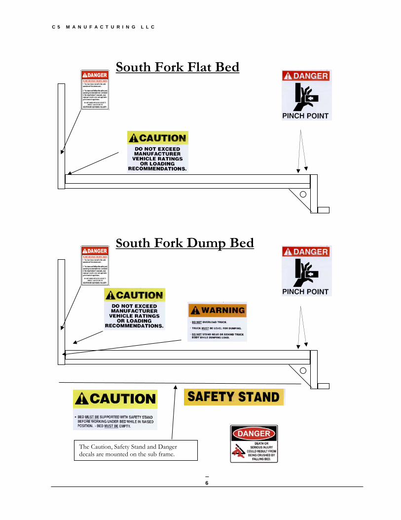
REMEMBER: If safety decals have been damaged, removed, become illegible or parts replaced without decals, new decals must be applied. New decals are available from your local dealer or the factory. Safety decal locations are shown below
Chisholm Trail Traditional Bale Bed
C 5 M A N U F A C T U R I N G L L C
6
South Fork Flat Bed
South Fork Dump Bed
The Caution, Safety Stand and Danger decals are mounted on the sub frame.

C 5 M A N U F A C T U R I N G L L C
7
Birdseye view of bed top There are 3 access doors located on the top of your bale bed.
1. The fluid fill access door (small round door closest to headache rack) 2. The Trailer hookup / Hitch ball access door (small square door in center) 3. The component access door (large square door closest to the rear edge of bed)
Fluid fill access door
Trailer hook-up / Hitch ball
Component Access Door

C 5 M A N U F A C T U R I N G L L C
8
SAFETY DECAL CARE
• Keep safety decals clean and legible at all times.
• Replace safety signs that are missing or have become illegible.
• Replaced parts that display a safety decal should also display the current decal.
• Safety decals are available from your C5 Dealer or call the C5 factory.
How to Install Replacement Safety Decals: • Be sure that the installation area is clean and dry.
• Decide on the exact position before you remove the backing paper.
• Remove the smallest portion of the split backing paper.
• Align the decal over the specified area and carefully press the small portion with the exposed sticky backing in place.
• Slowly peel back the remaining paper and carefully smooth the remaining portion of the decal in place.
• Small air pockets can be pierced with a pin and smoothed out by using the piece of decal backing paper.

C 5 M A N U F A C T U R I N G L L C
9
BEFORE OPERATION CHECK LIST
• Carefully study and understand this manual.
• Do not wear loose-fitting clothing which may catch in moving parts.
• Always wear protective clothing and substantial shoes.
• Give the unit a visual inspection for any loose bolts, worn parts or cracked welds, and make necessary repairs. Follow the maintenance safety instructions included in this manual.
• Be sure that there are no tools laying on or in the equipment.
• Do not use the unit until you are sure that the area is clear, especially of children and animals.
• Don’t hurry the learning process or take the unit for granted. Ease into it and become familiar with your new bale bed.
• Practice operation of your bale bed and its attachments. Completely familiarize yourself and other users with safe operating procedures.
• Do not allow anyone to stand between the back of the bed, or between the bed and the objects to be lifted.
• Do not allow anyone to stand near the pickup when loading or unloading hay. • Keep body parts away from pinch points. • Never operate under unsafe conditions. • Never check for leaking hydraulic fluid with hands. • Keep equipment in good operating condition and never operate bed beyond capacities.
C 5 M A N U F A C T U R I N G L L C
10
DURING OPERATION CHECK LIST
• Children should not be allowed to play on or operate the bale bed, it is a complicated piece of equipment intended for adult operation only.
• Clear the area of small children and bystanders before moving, loading, or unloading this unit.
• Never leave running equipment unattended. Keep hand control in a safe place, inaccessible from children and pets. The Arm function can be initiated while vehicle is turned off.
• Slow down for corners and rough terrain.
• Make sure you are in compliance with all local and state regulations regarding transporting equipment and hay on public roads and highways. Lights must be clean and visible by overtaking or oncoming traffic when feed or other loads are transported.
• Beware of bystanders, particularly children! Always look around to make sure that it is safe to operate your bale bed. This is particularly important with higher noise levels and quiet cabs, as you may not hear people shouting.
• Keep hands and clothing clear of moving parts.
• Do not clean, lubricate or adjust your equipment while in operation. Use access doors whenever possible while preforming routine maintenance.
• Be especially observant of the operating area and terrain - watch for holes, rocks or other obstacles. DO NOT operate near the edge of drop-offs or banks.
• DO NOT operate on steep slopes as truck roll over may result.
• Operate up and down (not across) intermediate slopes. Avoid sudden starts and stops.
• Avoid overhead wires or other obstacles. Contact with overhead lines could cause serious injury or death.
• Avoid loose fill, rocks, and holes; they can be dangerous for equipment operation or movement.
• Never stand alongside a unit while engaging the arm features.
• As a precaution, always re-check the hardware on equipment following every 100 hours of operation. Correct all problems. Follow the maintenance safety procedures.
• Do not over load your truck. The Arm lift capacity is 2850 lbs.

C 5 M A N U F A C T U R I N G L L C
11
FOLLOWING OPERATION CHECK LIST
• Do not park equipment where it will be exposed to livestock for long periods of time. Damage to the bale bed and livestock injury may result.
• Do not permit children to play on or around the stored unit.
HIGHWAY AND TRANSPORT OPERATIONS
• Adopt safe driving practices:
− Always drive at a safe speed relative to local conditions and ensure that your speed is low enough for an emergency stop to be safe and secure. Keep speed to a minimum.
− Reduce speed prior to turns, avoiding the risk of overturning.
− Avoid sudden uphill turns on steep slopes.
− Always keeps the vehicle in gear to provide engine braking when going downhill. Do not coast.
− Do not drink and drive!
• Comply with state and local laws governing highway safety and movement of farm machinery on public roads.
• Plan your route to avoid heavy traffic.
• Be a safe and courteous driver. Always yield to oncoming traffic in all situations, including narrow bridges, intersections, etc.
• Be observant of bridge loading ratings. Do not cross bridges rated lower than the gross weight at which you are operating your bale bed.
• Watch for obstructions overhead and to the side while transporting.
• Make sure any hay bales you are carrying do not obstruct the view of the trucks lights.
• Always operate equipment in a position to provide maximum visibility at all times. Make allowances for increased length and weight of the equipment when making turns, stopping the unit, etc.
• Pick the most level route possible when transporting across fields. Avoid the edges of ditches or gullies and steep hillsides.
• Be extra careful when working on inclines.
• Maneuver the vehicle at safe speeds.

C 5 M A N U F A C T U R I N G L L C
12
BED OPERATION (ARM FUNCTION)
BALE MOVING (Loading) – Back up to the bale – Stay about two feet from bale. Use a 1-2-3 step method for loading the bale.
STEP 1 – Depress LEFT Arm out to release LEFT arm from the bed (home position).
STEP 2 – Depress RIGHT Arm out switch to release RIGHT arm from the bed (home position)
MAKE SURE BOTH ARMS ARE FREE FROM BED
STEP 3 – Depress Unload switch until the arms are at the center of the bale. Depress
the Right Arm in and the Left Arm in switches to squeeze bale. Once the bale is squeezed, depress the Load switch to load bale on to the truck. Repeat procedure for 2nd bale. Keep arms squeezed on the 2nd bale to keep bales from rolling off the truck.
BALE MOVING (UNLOADING) – Use the reverse procedure from loading. BALE MOVING (UNROLLING) – If bed is equipped with spinners, unload bale onto the ground. Leave bale arms in squeezed (in) position. Cut the strings and drive forward until bales is unrolled.
WARNING BOTH BALE ARMS MUST BE IN THE OUT
POSITION BEFORE BALE MOVING

C 5 M A N U F A C T U R I N G L L C
13
Tethered Handheld Control Pendant diagram (Old Style)
White Black
Orange & Black Green Orange Blue
Red and Black Green Stripe
Blue Strip
White Stripe Black Stripe
Red Power in

C 5 M A N U F A C T U R I N G L L C
14
Tethered Handheld Control Pendant diagram (New Style)

C 5 M A N U F A C T U R I N G L L C
15
Tethered Handheld Control Pendant diagram (New Style)
To be removed
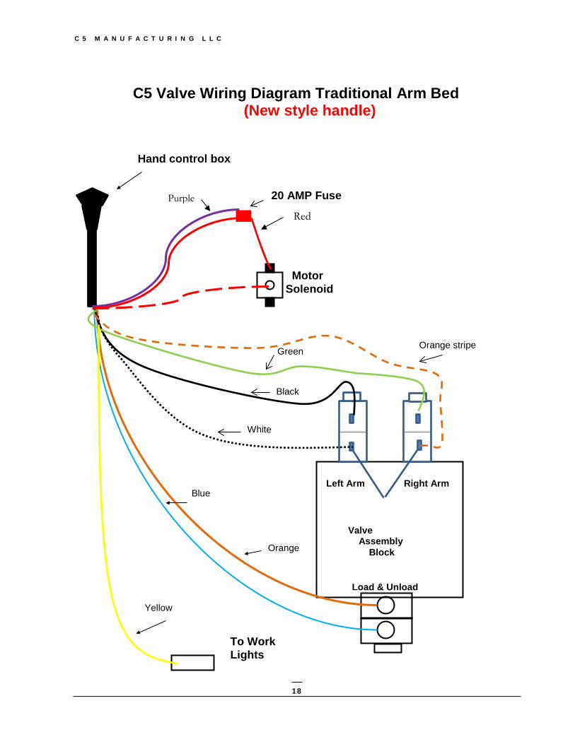
Wire Diagram Key Brown – Ground ** hook up 1st** Red – 12 V Solenoid Red/White – Exciter pin Solenoid Purple – 12 V Solenoid Yellow – Work Lights Orange – Unload Blue – Load Orange/White - Right Arm Out Green – Right Arm in White – Left Arm out Black – Left Arm in

C 5 M A N U F A C T U R I N G L L C
16
BED OPERATION (ARM FUNCTION)
BALE MOVING (Loading) – Back up to the bale – Stay about two feet from bale. While holding the pendant look at the 7 buttons. Left Arm out, Left Arm in, Right arm in, Load and Unload plus the Light on off button.
To grab a bale first Open both arms out pushing each button independently. When both arms are fully extended
away from the bed press the unload arm button. It will initiate the arms to rotate up and back. Back into the bale raise or load arms to center the spinners with the bale.
Now close arms by pushing the arm in buttons independently. Once bale is secure press the
load button to initiate the arms to rotate up allowing the bale to sit on the bed. If loading a second bale repeat the above instructions. Keep arms tight against the bale to insure the bale does not roll off the bed.
MAKE SURE BOTH ARMS ARE FREE FROM BED
BALE MOVING (UNLOADING) – Use the reverse procedure from loading. BALE MOVING (UNROLLING) – If bed is equipped with spinners, unload bale onto the ground. Leave bale arms in squeezed (in) position. Cut the strings and drive forward until bales is unrolled.

C 5 M A N U F A C T U R I N G L L C
17
C5 Valve Wiring Diagram Traditional Arm Bed (Old style handle)
Hand control box
To Work Lights
Green
White
Valve Assembly Block
Left Arm Right Arm
Load & Unload
Blue
Orange
Black
White
Orange Stripe Green
Red Stripe
20 AMP Fuse
Red
Blue Stripe
Motor Solenoid
Black Stripe
C 5 M A N U F A C T U R I N G L L C
18
C5 Valve Wiring Diagram Traditional Arm Bed (New style handle)
Hand control box
To Work Lights
Yellow
Valve Assembly Block
Left Arm Right Arm
Load & Unload
Blue
Orange
White
Black
Green Orange stripe
20 AMP Fuse
Motor Solenoid
Red
Purple

C 5 M A N U F A C T U R I N G L L C
19
Valve Assembly Diagram #1
Valve Assembly Block
Left Arm Right Arm
Load & Unload
Left Arm IN Left Arm OUT
Right Arm IN Right Arm OUT
Unload Load
Counter Balance Valve
Pressure Relief Valve
Piloted check valves
C 5 M A N U F A C T U R I N G L L C
20
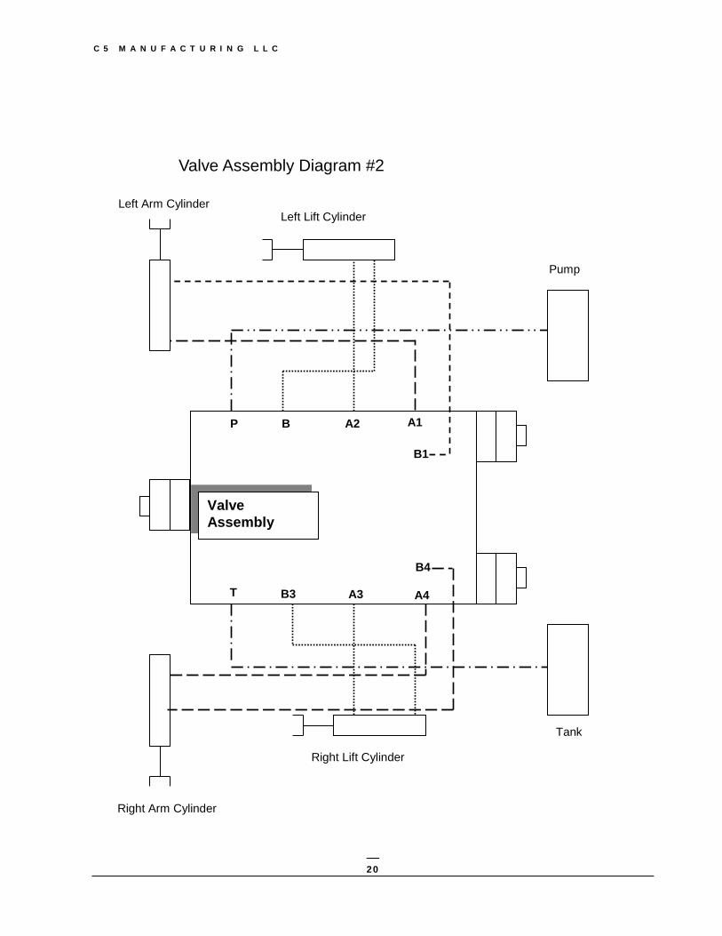
Valve Assembly Diagram #2
Left Arm Cylinder
Pump
Left Lift Cylinder
Right Arm Cylinder
Right Lift Cylinder
Tank
P
B1
A2 B
A3
B4
A1
A4 B3 T
Valve Assembly
C 5 M A N U F A C T U R I N G L L C
21
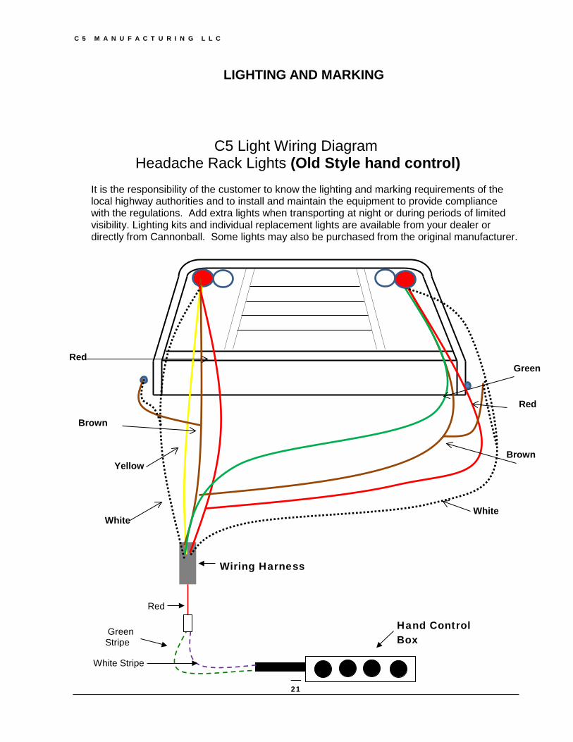
C5 Light Wiring Diagram Headache Rack Lights (Old Style hand control)
It is the responsibility of the customer to know the lighting and marking requirements of the local highway authorities and to install and maintain the equipment to provide compliance with the regulations. Add extra lights when transporting at night or during periods of limited visibility. Lighting kits and individual replacement lights are available from your dealer or directly from Cannonball. Some lights may also be purchased from the original manufacturer.
LIGHTING AND MARKING
Hand Control Box
Green Stripe
White Stripe
Red
Wiring Harness
Green
Red
Yellow
Brown
White White
Red
Brown
C 5 M A N U F A C T U R I N G L L C
22
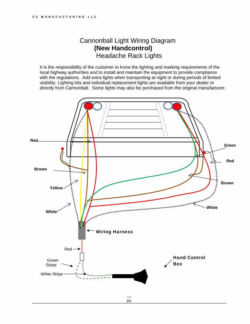
Cannonball Light Wiring Diagram (New Handcontrol)
Headache Rack Lights
It is the responsibility of the customer to know the lighting and marking requirements of the local highway authorities and to install and maintain the equipment to provide compliance with the regulations. Add extra lights when transporting at night or during periods of limited visibility. Lighting kits and individual replacement lights are available from your dealer or directly from Cannonball. Some lights may also be purchased from the original manufacturer.
Hand Control Box
Green Stripe
White Stripe
Red
Wiring Harness
Green
Red
Yellow
Brown
White White
Red
Brown
C 5 M A N U F A C T U R I N G L L C
23
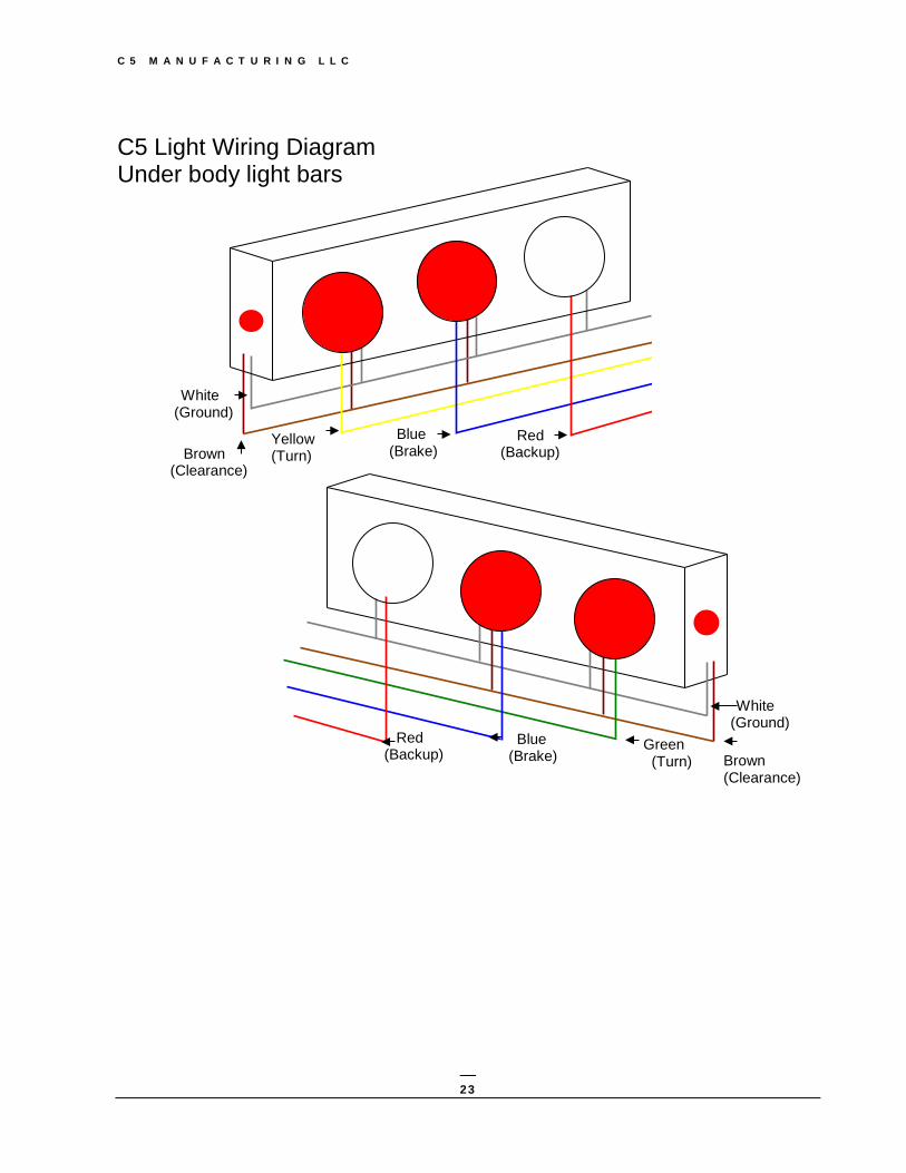
C5 Light Wiring Diagram Under body light bars
Brown (Clearance)
White (Ground)
Yellow (Turn)
Blue (Brake)
Red (Backup)
White (Ground)
Brown (Clearance)
Blue (Brake)
Red (Backup) Green
(Turn)

C 5 M A N U F A C T U R I N G L L C
24
PERFORMING MAINTENANCE
• Good Maintenance is your responsibility. Poor Maintenance is an invitation to trouble.
• Do not allow anyone to operate or perform maintenance on your C5 Bale Bed until they have had thorough training on how the unit works, a complete understanding of the safety precautions, and have read the owner’s manual.
• Use access doors whenever possible while preforming routine maintenance. • Make sure children and pets do not have access to the hand-held tethered control box or a
cord free remote as working parts of your bale bed may be engaged without the trucks motor running.
• Use extreme caution when making adjustments. (Call the factory if you have questions or
are unsure of possible outcomes)
• Make sure there is plenty of ventilation. Exhaust fumes from your truck may cause asphyxiation.
• Never replace hex bolts with less than grade five bolts unless otherwise specified.
• Where replacement parts are necessary for periodic maintenance and servicing, genuine factory replacement parts must be used to restore your equipment to original specifications. The manufacturer will not claim responsibility for use of unapproved parts and/or accessories and other damages as a result of their use.
• If equipment has been altered in any way from original design, the manufacturer does not accept any liability for injury or warranty.
• Safety devices, decals, and fuses are installed for your personal protection; please do not operate your C5 bale bed if safety devices appear altered or defective. If you are unsure call the factory, we will assist you.

C 5 M A N U F A C T U R I N G L L C
25
MAINTENANCE CHART
ITEM INTERVAL Visual inspection, walk around truck look for damage, leaks, accumulated debris, anything that looks unusual.
Daily
Check tire pressure. Before transporting Check for stress cracks or broken welds. Daily Clean dirt and debris from hinge and squeeze points.
Daily
Check for loose electrical connections (keeping them dry and tight).
Daily
Check all hydraulic components for damage or leaking fluids.
Daily
Check hydraulic hoses for proper clearance and movement when raising and lowering bed and arms. Replace broken zip ties and rubber straps.
Daily
Keep batteries in top working condition. Check ground wires for corrosion and poor contact with truck frame. Two batteries are required on all electric over hydraulic systems.
Weekly
Grease all 12 zerks Weekly Change oil filter (10 Micron) Bi-yearly, more often in dirty conditions Change Hydraulic fluid, Trans shield multi- purpose ATF or Mobile DTE 10 EX Arctic oil
When changing filter, more often in dirty conditions. Call factory with questions.
Clean and paint As needed Keep all safety decals in good visible condition. Replacements are available for a nominal fee.
Periodically as needed
Review safety instructions Periodically

C 5 M A N U F A C T U R I N G L L C
26
BED SPECIFICATIONS PLEASE NOTE THE MANUFACTURER RESERVES THE RIGHT TO SUBSTITUTE
PARTS AND VENDORS AT THEIR DISCRETION. Power unit 12v dc 1 hp motor/pump/Solenoid 4 gal pm C5 call Pump (only) C5 call Motor (only) C5 call Solenoid 3post Napa ST80 Solenoid 4 post Napa ST51 Solenoid heavy duty Trombetta call Valve Manifold (Cannonball 3 cartridge valve) C5 call Cylinder (squeeze) 2”x6” tie bolt with clevis ends varied 2x6 Cylinder (lift) 3”x20” tie bolt with clevis ends varied 3x20 Halogen Work light (headache rack) Peterson M525 Rectangular stop tail (headache rack) Peterson M305R LED Resistor harness Peterson 421-491RS LED 4” White Round Back-up Peterson M815C-3 LED 4”Red Stop/tail with 7 diodes Peterson M826R-3 LED 4” Red Stop/tail with 8 diodes Peterson M417R-5P LED x Lumen Peterson 22423R-4 LED Small Amber Clearance Peterson M177A LED 2 x 6 Red Oval Stop/turn Peterson call Incandescent 2 x 6 Red Oval Stop/turn Peterson call Incandescent 2 x 6 White Oval Back-up Peterson MZ421RX Incandescent 4” White Round Back-up Peterson M415 Incandescent 4” Red Round Stop/tail Peterson M42R Incandescent 2” Red Round Peterson 146R Grommets for all the above Peterson Call Pigtails for all the above Peterson Call Tag Lights Peterson MZ435N-X ID Bar Peterson M15-3R Reflectors (Red/Amber) Peterson call Trans shield multi-Purpose ATF (Transmission fluid) Mobile call Mobile DTE 10 EX (Artic Grade Hydraulic oil) Mobile call Replacement 10 micron Oil Filter Varied Napa-1551 Wix-51551 Small Electrical Parts Fuse (350 amp fuse) Vortex ANE-350A Fuse Block for 350 amp fuse) Vortex BLC-209 Fuse (20 amp with holder) Mize ACT20 Safety Switches (snap action) Grangers 6X286 10”Black ground cable Mize SS410 Grey rubber boots for safety switch Remote NC3030 Tethered Hand control Pendant Remote B-2194-23 Replacement Pendant switches Remote DPDT Power cable (double 00) welding cable 00 Other 2 5/16” 30# 1” riser hitch ball Buyers 1802050 Arm lift capacity Cannonball 2850#

C 5 M A N U F A C T U R I N G L L C
27
USE AND CARE TIPS FROM THE FACTORY 1. Keeping the BED clean and painted will help to prolong the usefulness of this product.
2. Failure to clean Bed routinely may cause a buildup of spoiled feed, mud and other
debris, which may become compacted or frozen. The resulting buildup may cause the bed to sit in a slightly unleveled position while resting on the sub-frame. At this point the safety switch will over-ride the arm out function. Always keep sub-frame free of debris. This applies to Arm/Dump beds only.
3. Two batteries in Top working condition are necessary for all Electric-over-hydraulic
Cannonball Bale beds.
4. Maintain good working grounds, free of corrosion and poor connections.
5. Grease the 12 zerk fittings. Keep bed in good lubrication to maintain function and longevity.
6. Keep all safety decals and devices in good visible condition
7. When in doubt, don’t hesitate to call. 620-532-3675
ASSISTANCE We are more than willing to answer any questions you may have on the functionality of your bed. Usually a quick call to your local dealer or directly to the factory will clear up any uncertainty. We are here to help. If you have any questions not answered in this manual, or require additional copies, or the manual is damaged, please contact your dealer or:
Contact us here at the factory: 620-532-3675
TROUBLESHOOTING
Call your local dealer or the factory for the latest trouble shooting help available.
620-532-3675 office line
316-772-1187 emergency and after hours line
620-491-3667 service direct line
316-772-1187 sales and service direct line
C 5 M A N U F A C T U R I N G L L C
28
C5 Engineering LLC 1005 E U.S. Hwy 54 Kingman, KS 67068
Phone 620-532-3675 • Fax 620-532-2604
Publication Date 2/17/2017