owner’s manual - aquapro pumps€¦ · safety instructions . 1. do not pump flammable or...
TRANSCRIPT

OWNER’S MANUAL
SHALLOW WELL JET PUMP
Questions, problems, missing parts? Before returning to the store call AQUAPRO Customer Service 8 a.m. - 5 p.m., EST, Monday-Friday
1-844-242-2475
© 2015 Copyright GP Enterprises Co., Ltd.
Model 60013/60023/60033 61013/61023 62013/62023
60043/61033/62033 61016/61026
SS Series 62013/62023
Tank Series 61033/60043/62033
Cast Iron Series 60013/60023/60033
Thermoplastic Series 61013/61023/ 61016/61026

2
PERFORMANCE
Model HP GPM of Water @ Total
Discharge Pressure of 40 psi Max. Pressure shutoff 0 ft. 5 ft. 10 ft. 15 ft. 20 ft. 25 ft.
60013/60043 1/2 7.2 6.5 6.0 5.5 5.0 4.5 66PSI 60023 3/4 9.2 9.0 8.1 7.4 6.8 5.8 67PSI 60033 1 14.0 12.6 12.0 10.5 9.2 7.0 67PSI
Model HP GPM of Water @ Total
Discharge Pressure of 40 psi Max. Pressure shutoff 0 ft. 5 ft. 10 ft. 15 ft. 20 ft. 25 ft.
61013/ 61016/61033 1/2 7.2 6.5 6.0 5.5 5.0 4.5 66PSI 61023/61026 3/4 9.2 9.0 8.1 7.4 6.8 5.8 67PSI
Model HP GPM of Water @ Total
Discharge Pressure of 40 psi Max. Pressure shutoff 0 ft. 5 ft. 10 ft. 15 ft. 20 ft. 25 ft.
62013 3/4 5.8 5.4 5.0 4.6 4.2 4.0 66PSI 62023/62033 3/4 7.4 6.7 6.3 5.9 5.4 4.9 66PSI
SAFETY INSTRUCTIONS
1. Do not pump flammable or explosive liquids such as oil, gasoline, kerosene, ethanol, etc. Do not use in the presence of flammable or explosive vapors. Using this pump with or near flammable liquids can cause an explosion or fire, resulting in property damage, serious personal injury, and/or death.
2. ALWAYS disconnect the power to the pump before servicing. 3. Do not touch the motor housing during operation. The motor is designed to operate at high temperatures. Do not
disassemble the motor housing. 4. Do not handle the pump or pump motor with wet hands or when standing on a wet or damp surface, or in water. 5. Wear safety goggles at all times when working with pumps. 6. This is a dual voltage 115/230 V pump. VOLTAGE SELECTOR INSIDE PRESET TO 230V. For 115V selection, please
open the terminal cover and set the switch to the proper voltage.For 61016/61026, this pump is built- in automatic dual-voltage selector switch and voltage can be converted by automatically. All wiring should be performed by a qualified electrician.
7. Protect the electrical cord from sharp objects, hot surfaces, oil, and chemicals. Avoid kinking the cord. Do not use damaged or worn cords.
8. Failure to comply with the instruction and designed operation of this unit may void the warranty. ATTEMPTING TO USE A DAMAGED PUMP can result in property damage, serious personal injury, and/or death.
9. The pump should be connected to a 230V/115V,GFCI outlet protected with a 10 amp(230V)/20 amp(115V) fuse or circuit breaker.
10. Know the pump and its applications, limitations, and potential hazards. 11. Secure the pump to a solid base. 12. Periodically inspect the pump and system components. Disconnect the pump from the power supply before inspecting. 13. Follow all local electrical and safety codes, along with the National Electrical Code (NEC). In addition, all Occupational
Safety and Health Administration (OSHA) guidelines must be followed.

3
14. The motor of this pump has a thermal protector that will trip if the motor becomes too hot. The protector will reset itself once the motor cools down and an acceptable temperature has been reached. The pump may start unexpectedly if it is plugged in.
15. Ensure the electrical power source is adequate for the requirements of the pump. 16. This pump is made of high-strength, corrosion-resistant materials. It will provide trouble-free service for a long time
when properly installed, maintained, and used. However, inadequate electrical power to the pump, dirt, or debris may cause the pump to fail. Please carefully read the manual and follow the instructions regarding common pump problems and remedies.
PRE-INSTALLATION
APPLICATION This unit is a single stage jet pump designed for shallow water well applications, where the water level is less than 25 ft. deep. If the water level to the pump is deeper than 25 ft., a convertible jet pump or a deep well submersible pump should be used. A pressure switch pre-set at 30 psi “on”, 50 psi “off” has been installed on the pump. The pressure switch will automatically turn the pump on and off based on the system pressure.
TOOLS REQUIRED
MATERIALS REQUIRED (NOT INCLUDED) One can PVC cement & primer (read instructions carefully) One well seal with vent plug One can thread compound (read instructions carefully) Foot valve Teflon tape Discharge tee/Priming tee and plug Rigid pipe Relief valve Check valve Adaptor
Flexible plastic pipe/clamps Tank(for TANK series tank is included)
Tee WARNING: All joints and connections must be AIRTIGHT. A single leak will prevent the proper operation of the pump. Wrap thread tape clockwise on all threaded connections. For all non-threaded connections, you must use PVC Purple Primer and PVC Cement to ensure airtight seals. Measure all pipe lengths before attaching. NOTE: A foot valve is a check valve that is used to keep the water from running back into the well from the pump and maintain hydraulic pressure when the pump is not running. If the foot valve does not hold the water the pump will lose it’s prime and will not pump water. If the foot valve open pressure is too high (the spring is too stiff), or the flow area is too small, the pump suction head and flow rate will significantly drop.
Phillips Screwdriver
Flathead Screwdriver
Thread Tape Tape Measure Safety goggles
Pipe wrench Hacksaw
PVC glue

4
NOTE:For61013/61023/61033/61016/61026.The suction pipe size should not be less than 1-1/4 in. the suction size of this pumpis 1-1/4 in. FNPT. For 60013/60023/60033/62013/62023/60043/62033, the suction pipe size should not be less than 1in. the suction size of this pump is 1 in. FNPT.
SPECIFICATIONS POWER SUPPLY 115V/230V,60HZ,20/10Amp circuit LIQUID TEMP. RANGE 32°F to 77°F (0°- 25°C) DISCHARGE 1in. FNPT
SUCTION 61013/61023/61033/61016/61026:1-1/4 in. FNPT 60013/60023/60033/62013/62023/60043/62043:1 in. FNPT
WATER LEVEL 25 ft.
INSTALLATION WARNING: ELECTRICAL SAFETY Capacitor voltage may be hazardous. To discharge the motor capacitor, hold the insulated handle screwdriver BY THE HANDLE and short capacitor terminals together. Do not touch the metal screwdriver blade or capacitor terminals. If in doubt, consult a qualified electrician. CAUTION: Do not touch an operating motor. Modern motors are designed to operate at high temperatures. To avoid burns when servicing the pump, allow it to cool for 20 minutes after shut-down before handling. Do not allow pump or any system component to freeze. To do so will void warranty. Pump water only with this pump. Periodically inspect the pump and system components. Wear safety glasses at all times when working on pumps. Keep the work area clean, uncluttered and properly lighted; store properly all unused tools and equipment. Keep visitors at a safe distance from the work areas. WARNING: The pump body may explode if used as a booster pump unless a relief valve capable of passing full pump flow at 75 psi is installed.
SHALLOW WELL JET PUMP INSTALLATIONS Have a vertical depth between the pump and the water being pumped of 25 ft. or less Have one pipe from the well to the pump case Can be installed in a bored or drilled well, or in a driven well
REPLACING AN OLD PUMP WARNING: Hazardous voltage. Disconnect power to the pump before working on a pump or a motor. Drain and remove the old pump. Check the old pipe for scale, lime, rust, etc., and replace it if necessary. Install the pump in the system. Make sure that all pipe joints in the suction pipe are air-tight as well as water tight. If the
suction pipe can suck air, the pump will not be able to pull water from the well.

5
Adjust the pump mounting height so that the plumbing connections do not put a strain on the pump body. Support the pipe so that the pump body does not take the weight of piping or fittings.
You have just completed the well plumbing for your new shallow well jet pump. Please go to discharge pipe and tank connections section.
WELL POINT (DRIVEN POINT) INSTALLATION Drive the well, using drive couplings and a drive cap. Drive fittings are threaded all the way through and allow the pipe
ends to butt against each other so that the driving force of the maul is carried by the pipe and not by the threads. The ordinary fittings found in hardware stores are not threaded all the way through the fitting and can collapse under impact. Drive fittings are also smoother than standard plumbing fittings, making ground penetration easier.
Mount the pump as close to the well as possible. Use the fewest possible fittings (especially elbows) when connecting the pipe from the well point to the pump suction
port. The suction pipe should be at least as large as the suction port on the pump (include a check valve as close to the well as possible). Support the pipe so that there are no dips or sags in the pipe, so it does not strain the pump body, and so that it slopes slightly upward from the well to the pump (high spots can cause air pockets which can air lock the pump). Seal the suction pipe joints with teflon tape. Joints must be air and water-tight. If the suction pipe can suck air, the pump cannot pull water from the well. If one well point does not supply enough water, consider connecting two or three well points to one suction pipe.
You have just completed the suction piping for your new shallow well jet pump. Please go to discharge pipe and tank connections section.
CASED WELL INSTALLATION, 2 IN. OR LARGER CASING Mount the pump as close to the well as possible. Assemble the foot valve, strainer, and well pipe. Make sure that the foot valve works freely. Lower the pipe into the well until the strainer is 5 ft. above the bottom of the well. It should also be at least 10 ft. below
the well’s water level while the pump is running in order to prevent the pump from sucking air. Install a sanitary well seal. Install a priming tee, priming plug, and suction pipe to the pump. Connect the pipe from the well to the pump suction port,
using the fewest possible fittings – especially elbows – as fittings increase friction in the pipe (however, include a foot valve). The suction pipe should be at least as large as the suction port on the pump. Use teflon tape on threaded pipe
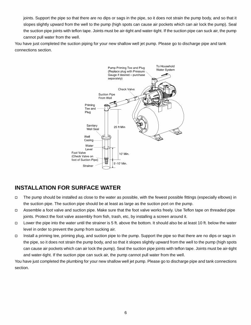
6
joints. Support the pipe so that there are no dips or sags in the pipe, so it does not strain the pump body, and so that it slopes slightly upward from the well to the pump (high spots can cause air pockets which can air lock the pump). Seal the suction pipe joints with teflon tape. Joints must be air-tight and water-tight. If the suction pipe can suck air, the pump cannot pull water from the well.
You have just completed the suction piping for your new shallow well jet pump. Please go to discharge pipe and tank connections section.
INSTALLATION FOR SURFACE WATER The pump should be installed as close to the water as possible, with the fewest possible fittings (especially elbows) in
the suction pipe. The suction pipe should be at least as large as the suction port on the pump. Assemble a foot valve and suction pipe. Make sure that the foot valve works freely. Use Teflon tape on threaded pipe
joints. Protect the foot valve assembly from fish, trash, etc, by installing a screen around it. Lower the pipe into the water until the strainer is 5 ft. above the bottom. It should also be at least 10 ft. below the water
level in order to prevent the pump from sucking air. Install a priming tee, priming plug, and suction pipe to the pump. Support the pipe so that there are no dips or sags in
the pipe, so it does not strain the pump body, and so that it slopes slightly upward from the well to the pump (high spots can cause air pockets which can air lock the pump). Seal the suction pipe joints with teflon tape. Joints must be air-tight and water-tight. If the suction pipe can suck air, the pump cannot pull water from the well.
You have just completed the plumbing for your new shallow well jet pump. Please go to discharge pipe and tank connections section.

7
DISCHARGE PIPE AND PRESSURE TANK CONNECTIONS
PRE-CHARGE TANK CONNECTION Install two tees in the pump discharge port. The pipe size must be at least as large as the discharge port.
NOTE: A pre-plumbed pump-on-tank system only requires one tee. Run a pipe or reinforced hose from one arm of the first tee to the port on the pre-charged tank. Connect the other discharge tee to your plumbing system. Check the pre-charge of air in the tank with an ordinary tire gauge. Your new pump has a 30/50 PSI switch, so adjust
the tank pre-charge pressure to 28 PSI. The pre-charge is measured when there is no water in the tank. The pre-charge should be 2 PSI less than the cut-in setting of the pump’s pressure switch.
Congratulations! You have just completed the tank connection for your jet pump.

8
NOTE: Sealing Pipe Joints. Use only teflon tape for making all threaded connections to the pump itself. Do not use pipe joint compounds on plastic: they can react with the plastic. Make sure that all pipe joints in the suction pipe are air tight as well as water tight. If the suction pipe can suck air, the pump will not be able to pull water from the well.
STANDARD TANK CONNECTION Wrap all threads with thread tape. In order for the pump and the pressure tank (sold separately) to operate properly, the pressure tank needs to be drained
of all water BEFORE INSTALLING IT TO THE PUMP. Thread a 10 in. tank tee (sold separately) or another necessary size tee into the pressure tank. Plug one outlet on top of the tank tee with a 1/4 in. plug (sold separately) and install a pressure gauge (sold separately)
on the other outlet on top of the tank tee. Thread two 1 in. female PVC adaptors (sold separately) onto the two inlet sides of the tank tee. Thread a 1/2 in. relief valve and a 1/2 in. drain valve (both sold separately) to the front of the tank tee. Congratulations! You have just completed the tank connection for your jet pump.
Pressure Switch Assembly Instructions WARNING: It is recommended all electrical work be performed by a licensed electrician. WARNING: Before wiring the pressure switch, turn off the power source to which you are connecting to avoid potentially life threatening electrical shock. WARNING: When wiring from the power source to the pressure switch, it is recommended that you use either a 14-gauge or 12-gauge cord. To complete the installation, you must connect the power source to the pressure switch. A 30/50 psi pressure switch has been installed on the pump. The pressure switch allows for automatic operation; the pump starts when pressure drops to the “cut-in” setting (30 psi pre-set).

9
To wire the pressure switch: Remove the pressure switch cover on the pump to expose the wiring terminals. Connect the green ground wire of the power supply to the switch ground terminal. Connect the power supply wires to the two outside terminals marked “LINE” and replace the switch cover. CAUTION: Do NOT use a pressure switch set at a pressure greater than 50 psi. The pump will not create pressures greater than 50 psi, if so the pump will never shut off, resulting in damage to the pump and voiding the warranty. Voltage Setting For 60013/60023/60033/61013/61023/62013/62023/60043/61033/62033 This pump is pre-wired at 230 volts. If the power source is 115 volts, remove the electrical housing cover. Flip the switch to 115 volts. Replace the cover.
For 61016/61026 The motor is 115/230 Volt single phase. This pump is built- in automatic dual-voltage selector switch and voltage can be converted by automatically. NOTE: All electrical work should be performed by a licensed electrician.
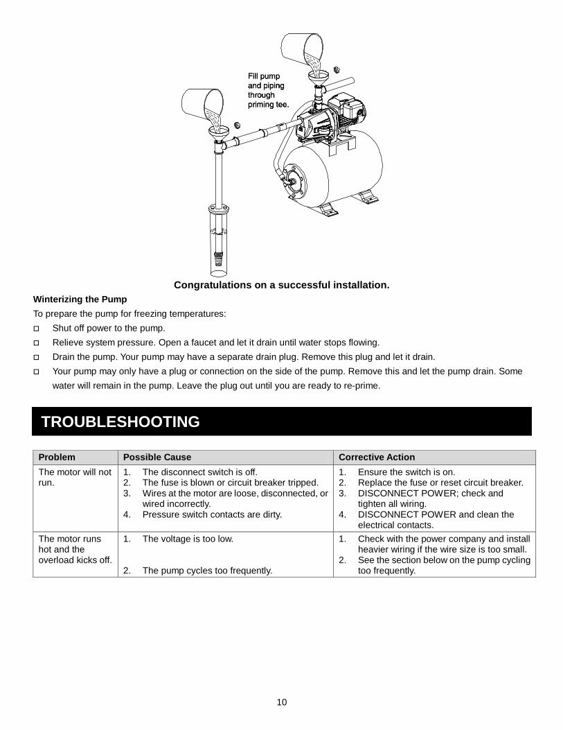
PRIMING WARNING: Never run the pump against a closed discharge. To do so can boil water inside the pump, causing hazardous pressure in the unit, risk of explosion and possibly scalding persons handling the pump. CAUTION: Never run the pump dry. Running the pump without water may cause the pump to overheat, damaging the seal and possibly causing burns to persons handling the pump. Fill the pump with water before starting. Remove the priming plug from the priming tee and fill the pump. Fill all piping between the pump and the well and make
sure that all piping in the well is full. If you have also installed a priming tee in the suction piping, remove the plug from the tee and fill the suction piping.
Replace all fill plugs (use teflon tape). Power on! Start the pump. If you do not have water in 2 minutes, stop the pump and remove the fill plugs. Refill the
pump and piping. You may have to repeat this several times in order to get all the trapped air out of the piping. A pump lifting water 25 ft. may take as long as 15 minutes to prime.
After the pump has built up pressure in the system and shut off, check the pressure switch operation by opening a faucet or two and running enough water out to bleed off pressure until the pump starts. The pump should start when pressure drops to 30 PSI and stop when pressure reaches 50 PSI. Run the pump through one or two complete cycles to verify correct operation. This will also help clean the system of dirt and scale dislodged during installation.
10
Congratulations on a successful installation.
Winterizing the Pump To prepare the pump for freezing temperatures: Shut off power to the pump. Relieve system pressure. Open a faucet and let it drain until water stops flowing. Drain the pump. Your pump may have a separate drain plug. Remove this plug and let it drain. Your pump may only have a plug or connection on the side of the pump. Remove this and let the pump drain. Some
water will remain in the pump. Leave the plug out until you are ready to re-prime.
TROUBLESHOOTING
Problem Possible Cause Corrective Action The motor will not run.
1. The disconnect switch is off. 2. The fuse is blown or circuit breaker tripped. 3. Wires at the motor are loose, disconnected, or
wired incorrectly. 4. Pressure switch contacts are dirty.
1. Ensure the switch is on. 2. Replace the fuse or reset circuit breaker. 3. DISCONNECT POWER; check and
tighten all wiring. 4. DISCONNECT POWER and clean the
electrical contacts. The motor runs hot and the overload kicks off.
1. The voltage is too low. 2. The pump cycles too frequently.
1. Check with the power company and install heavier wiring if the wire size is too small.
2. See the section below on the pump cycling too frequently.

11
Problem Possible Cause Corrective Action The motor runs but not water is delivered*. * (Note: Stop the pump; then check the prime before looking for other causes. Unscrew the priming plug and see if water is in the priming hole).
1. Pump in new installation did not pick up prime through: a) Improper priming b) Air leaks
c) Leaking foot valve or check valve
2. Pump has lost prime through.
a) Air leaks
b) Water level below suction pipe inlet 3. The foot valve or strainer is plugged. 4. The ejector or impeller is plugged. 5. The check valve or foot valve is stuck shut. 6. Pipes are frozen. 7. The foot valve and/or strainer are buried in
sand or mud. 8. Water level is too low for shallow well setup to
deliver water.
1. In new installation: a) Re-prime according to instructions. b) Check all connections on the suction
line, AVC, and ejector with shaving cream.
c) Replace the foot valve or check valve. 2. In installation already in use:
a) Check all connections on the suction line and well seal.
b) Lower the suction line into water and re-prime. If receding water level in the well exceeds 25 ft. (7.6 M), a deep well pump is needed.
3. Clean the foot valve or strainer. 4. Clean the ejector or impeller. 5. Replace the check valve or foot valve. 6. Thaw pipes. Bury pipes below the frost
line. Heat the pit or pump house. 7. Raise a foot valve and/or strainer above
the bottom of the water source. Clean the foot valve and strainer.
8. A deep well pump may be needed (over 25 ft. to water) to deliver water.
The pump does not deliver water to full capacity.
1. The water level in the well is lower than estimated.
2. Steel piping (if used) is corroded or limed, causing excess friction.
3. Piping is too small in size. 4. The well point is packed.
1. A deep well jet will be needed if your well is more than 25 ft. (7.6 M) depth to water.
2. Replace with plastic pipe where possible, otherwise with new steel pipe.
3. Use larger piping. 4.Backflush the well point or sink new point.
The pump delivers water but does not shut off or the pump cycles too frequently.
1. The pressure switch is out of adjustment or contacts are welded together.
2. Faucets have been left open. 3. The venturi, nozzle or impeller is clogged. 4. The standard pressure tank is waterlogged
and has no air cushion. 5. The pipes are leaking. 6. The foot valves are leaking. 7. The air charge is too low in the pre-charged
tank.
1. DISCONNECT POWER; adjust or replace the pressure switch.
2. Close the faucets. 3. Clean the venturi, nozzle or impeller. 4. Drain the tank to air volume control port.
Check AVC for defects. Check all connections for air leaks.
5. Check the connections. 6. Replace the foot valves. 7. DISCONNECT POWER and open faucets
until all pressure is relieved. Using a tire pressure gauge, check air pressure in the tank at the valve stem located on the tank. If necessary, adjust air pressure in the tank to 28 PSI (2 PSI lower than switch cut-in setting). Check the air valve for leaks (use shaving cream) and replace core if necessary.
Air spurts from the faucets.
1. The pump is picking up prime. 2. There is a leak in the suction side of the pump.
3. The well is gaseous. 4. Intermittent over-pumping of the well.(Water
drawn down below the foot valve.)
1. When pump has picked up prime, it should pump solid water with no air.
2. The suction pipe is sucking air. Check joints for leaks with shaving cream.
3. Consult the factory about installing a sleeve in the well.
4. Lower the foot valve if possible, otherwise restrict pump discharge.

12
WARRANTY Limited Warranty WHAT THIS WARRANTY COVERS When used and maintained in normal use and in accordance with the Owner’s Manual, your AQUAPRO product is warranted against original defects in material and workmanship for at least one year (warranty varies depending on model; see box for specific warranty information) from the date of purchase (the “Warranty Period”). During the Warranty Period, AQUAPRO will repair or replace at no cost to you, to correct any such defect in products founds upon examination by AQUAPRO to be defective in materials or workmanship. WHAT THIS WARRANTY DOES NOT COVER This Warranty does not cover: Use of the product in a non-residential application, improper installation and/or maintenance of the product, damage due to misuse, acts of God, nature vandalism or other acts beyond control of AQUAPRO, owner’s acts or omissions, use outside the country in which the product was initially purchased and resale of the product by the original owner. This warranty does not cover pick up, delivery, transportation or house calls. However, if you mail your product to an AQUAPRO Sales and Service Center for warranty service, cost of shipping will be paid one way. This warranty does not apply to products purchased outside of the United States, including its territories and possessions, outside of U.S. Military Exchange and outside of Canada. This warranty does not cover products purchased from a party that is not an authorized retailer, dealer or distributor of AQUAPRO products. OTHER IMPORTANT TERMS This warranty is not transferable and may not be assigned. This Warranty shall be governed and construed under laws of the state of Michigan. The Warranty Period will not be extended by any replacement or repair performed under this Warranty. THIS WARRANTY IS THE EXCLUSIVE WARRANTY AND REMEDY PROVIDED BY AQUAPRO. ALL OTHER WARRANTIES, EXPRESSED OR IMPLIED, INCLUDING WARRANTIES OR MERCHANTABILITY OR FITNESS FOR PARTICULAR PURPOSE, ARE DISCLAIMED. IN NO EVENT WILL AQUAPRO BE LIABLE FOR ANY SPECIAL, INDRECT, INCIDENTAL OR CONSEQUENTIAL DAMAGES OF ANY KIND OR NATURE TO OWNER OR ANY PARTY CLAIMING THROUGH OWNER WHETHER BASED IN CONTRACT, NEGLIGENCE, TORT, OR STRICT PRODUCTS LIABLITY OR ARISING FROM ANY CAUSE WHATSOEVER. Some states do not allow for the exclusion of consequential damages, so the above exclusion may not apply to you. This warranty gives you specific rights. You may also have others that vary from state to state.
Thank you for choosing an AQUAPRO product!