owners instruction manual - jk fabricationjkfabrication.com/content/jkfab single reduction anchor...
TRANSCRIPT

OWNERS INSTRUCTION MANUAL
FOR J.K. FABRICATION, INC.
MODELS 18”, 20”, 24”, 26”, 28”, AND 32”
ALUMINUM, STAINLESS STEEL, AND GALVANIZED STEEL
SINGLE REDUCTION ANCHOR WINCHES
CUSTOMER: DATE: MODEL: SERIAL NUMBER: HYDRAULIC MOTOR MODEL NUMBER: DIRECTIONAL CONTROL VALVE MODEL NUMBER: EQUIPPED WITH BRAKE? ____ YES ____ NO MAXIMUM ANCHOR WEIGHT: LBS RECOMMENDED HYDRAULIC FLOW AND PRESSURE: GPM @ PSI
3101 West Commodore Way #3
Seattle, WA 98199 Phone: 206-297-7400
Fax: 206-297-1300 [email protected]

GENERAL
SINGLE REDUCTION ANCHOR WINCH
INSTRUCTIONS
A. General Description
The J.K. Fabrication Single Reduction Anchor Winch is constructed to
provide many years of reliable service, being built with the finest Marine Grade
Materials and utilizing the proven RE Series of hydraulic motors from White
Hydraulics. The Winch is designed to haul (or pay-out) rope (or cable) by the
rotation of the hydraulic powered drum. It is important that the Anchor Winch
be mounted “in-line” with the vessel Bow Roller, so that the incoming rope (or
cable) spools onto the winch drum as evenly as possible.
Your new J.K. Fabrication Single Reduction Anchor Winch may or may not
be equipped with the Optional Winch Brake manually operated by a Handbrake
Wheel.
Contact J.K. Fabrication for recommendations and circuit diagrams before
adding an Anchor Winch to your hydraulic system.
CAUTION
AS WITH ANY WINCH OR HOIST, EXTREME CARE MUST
BE FOLLOWED TO PREVENT INJURY WHILE IN USE. DO
NOT OPERATE THE J.K. FABRICATION ANCHOR WINCH
IN AN UNSAFE MANNER AT ANY TIME.

B. Anchor Winch Installation
The J.K. Fabrication Anchor Winch must be securely mounted to a rigid
surface, which will not flex when the winch is in use. The winch should be
mounted with the centerline of the drum in a horizontal position. Also consider
the strength of the deck the winch will be installed onto, along with any needed
winch foundation, which may be necessary to strengthen (and/or to secure) the
winch to the deck, along with the location of the hydraulic hose connections.
In determining the Anchor Winch hauling location, you should consider that the
J.K. Fabrication Anchor Winch will spool the rope (or cable) onto the drum
more evenly if the winch is mounted farther from the bow roller. The closer the
winch is to the roller, the more un-even the rope (or cable) will spool onto the
drum, as the fleet angle is greater.
Secure the winch to your deck using best practice. Remember, you may not
have to anchor very often, but when you do, you’ll want the anchor winch to
hold, and not fail. If you have any doubt, consult your naval architect. Note:
Large holes are provided in the winch housing to aid in mounting. Use Bolts of
adequate Size and Strength to mount the Anchor Winch keeping in mind the
intended load on the winch.
The J.K. Fabrication Anchor Winch is Pre-plumbed with a Directional Control
Valve for easy installation (see Fig. 1 below for Typical Connection of
Hydraulic Lines to Winch Control Valve).
Figure 1- Typical Hose Connections
Return ‘Out’ to
Tank
Pressure ‘In’ from
Hydraulic Pump

C. General Anchor Winch Operation
As the J.K. Fabrication Anchor Winch is equipped with a Push-Pull operated
Valve Spool having four positions, moving the valve control handle will cause
the winch to:
1) Haul-in
2) Center or neutral (Hold Position)
3) Pay-out
4) Float-position or free-wheel
Figure 2- Control Valve Handle Positions
NOTE: The J.K. Fabrication Anchor Winch Directional Control Valve is
equipped with a Relief Valve ‘Factory-Set to 1500 PSI.’ Adjustment of this
valve is possible should customer desire to change. Please consult J.K.
Fabrication for instructions prior to adjusting.
NOTE: Even though the Directional Control Handle is designed to be re-
positional, NEVER re-position the handle while the Hydraulic Power is on, as
loss of winch control could be the result!
Haul-In Position
Center-Stop-Hold Position
Pay-Out Position
Free-Spool Position

NOTE: Spool Cable onto the Drum in Overwound direction, and always have
AT LEAST TWO LAYERS of Cable on the Drum UNUSED during payout.
The J.K. Fabrication Anchor Winch is equipped with a locking Dog to firmly
lock the drum while anchored. NOTE: Wire Cable must be spooled
‘Overwound’ onto the Drum for the Dog to work properly.
Drum Dog Operation: Upon completion of Pay-out of Anchor and Cable,
Loosen Dog Wing Nut, Rotate Dog Clip towards the Anchor allowing the dog
arm (pawl) to engage the drum ratchet. (See Fig. 3 and Fig.4)
NOTE: Always have the Drum Dog ‘ENGAGED’ while anchored, AND
while hauling in your Cable and Anchor!
Figure 3- Locking Dog Position “A”
Allows Drum to Rotate Freely
Figure 4- Locking Dog Position “B”
Engages Drum-Dog to Drum, Locking Drum While Anchored
DIS-ENGAGED
Position
ENGAGED
(Drum Locked) Position
Rotate Dog Clip to allow the Dog
Arm to Engage the Drum Ratchet

Figure 4- Locking Dog Operation Drawing
Dog Secured by Clip Dis-Engages Drum-Dog to Drum, Allowing Drum to Turn Dog Released from Clip Engages Drum-Dog to Drum, Locking Drum While Anchored
NOTE!
DO NOT Engage ‘Locking Dog’ while Anchor Winch is Free-spooling Out
or Powering Out!
RB Series Anchor Winch Operation:
As stated above, the Anchor Winch is controlled with the supplied 4-position Bi-
directional hydraulic control valve. The 4 positions include, power-in, power-out,
neutral, and a Detented (Float) position. The Information which follows covers the
operation of all 18”, 20”, 24”, 26”, 28”, and 32” Single reduction Anchor Winches
that are equipped the optional, manual Handbrake Wheels.
Follow the steps in the order below to operate the Winch:
1- When deploying the anchor, power the drum out until the anchor is free
from the bow. Stop the winch drum by slowly releasing the valve handle to
its neutral (or spring-centered) position. With the handle in this position, the
drum will stop.
2- Rotate the Handbrake Wheel in a Clockwise Direction until it becomes
‘Snug’, tightening the Band Brake to the Brake Drum.
Locking Drum Dog
Drum Dog Ring
Dog Clip

3- Shift the Hydraulic Control Valve Handle to its full travel (Detented)
position. The user will note that the valve handle will hold itself in this
Detented (Drum Free-spool) position.
4- Slowly begin to release the brake by rotating the Handbrake Wheel in a
Counter-Clockwise Direction. Deployment speeds of 80 to 140 Feet per
Minute are normal.
NOTE!
It’s very important to leave some tension on the Brake Band as the Anchor is
being deployed. Do not release the Handbrake Wheel completely during
deployment. When the Anchor reaches the ocean floor or seabed, the drum
could over-rotate (due to the inertia of the rotating drum) causing the cable to
turn into a ‘Bird’s Nest’, if some tension is not left on the Band Brake.
NOTE!
Never use the Hydraulic Control Valve or Shift the Valve Handle from its
‘Float-position’ to slow down or to stop the winch drum during anchor
deployment. Use ONLY the Handbrake Wheel to slow and stop the anchor
during deployment.
5- Once the Anchor is safely on the ocean floor or seabed, turn the Handbrake
Wheel in a Counter-Clockwise Direction to further release the Band Brake
completely. When the Handbrake Wheel is rotated Counter-Clockwise
completely, the user will notice the Brake Handwheel will come up against a
‘stop’. Come-up easy against this ‘Stop’… Don’t apply high torque after the
stop is reached.
NOTE!
Failure to completely release the Handbrake Wheel after the anchor reaches
bottom will prematurely wear out the Brake Band, and cause the Hydraulic
Motor to work harder. If maximum anchor weight is used, it can also cause
the Drive Chain and Sprockets to wear faster than normal.
6- The operator may now pay-out cable and chain until the desired ‘scope’ is
achieved.
NOTE!
NEVER SPOOL OFF THE LAST TWO LAYERS of rode on the drum core!

7- Now loosen the Dog Clip by turning the wing nut in a Counter-Clockwise
Direction. Move the Dog Clip forward allowing the Dog Arm to engage the
Dog Ring.
NOTE!
Always use the Dog System. Failure to use the Dog System will break and
damage the Drive Side Components. Never engage the Dog System during
anchor deployment (or when the drum is being rotated in a Free-spool or
power-out direction). Keep the Dog System engaged during all anchoring, as
well as when bringing up the anchor, especially as the anchor approaches the
Bow Roller. Once the Anchor reaches the waterline, see the Very Important
Note that follows to ensure that the Anchor may be deployed easily the next
time.
VERY IMPORTANT NOTE!
As the anchor is hauling-in and reaches the waterline, bring the winch to a
stop by slowly releasing the valve handle to its Spring-loaded Center Position.
At this point, the user must DIS-ENGAGE THE DOG into Position A
(allowing the drum to rotate freely). The user may now bring up the anchor
and snug to the Bow Roller. NEVER leave the Dog engaged to the Drum
when the anchor is snug to the Bow Roller, as the Dog Arm could jam tight,
thereby not allowing anchor deployment on the next set.
D. Wire Cable Installation
All J.K. Fabrication Anchor Winches are designed to ‘Over-Spool’: that is, the
cable or line must be led onto the drum above the Core Barrel. This orientation
allows the Drum Dog Pawl to work properly.
Located on the Drum Core Barrel is the Cable Hold Tube. This Tube is welded
securely to the Core Barrel internal structures, and is fitted with set screws.
When spooling onto the drum, the cable is held fast by this tube and the
tightened set screws. The Sole purpose of this arrangement is to allow the
initial spooling of the cable onto the drum.
NOTE: THE CABLE HOLD TUBE AND SET SCREWS ARE NOT DESIGNED TO
WITHSTAND ANY LOADS GENERATED DURING THE USE OF THE WINCH.

J.K. Fabrication strongly recommends a minimum wire capacity of Two
Layer’s deep on all J.K. Fabrication Winches during operation. This
means that the 1st and 2
nd layers of wire in direct contact with the Core
Barrel must never be wound or unwound when the winch is under loaded
conditions. This condition insures secure handling of the intended loads,
along with safe operation of the winch.
ALL WINCH OPERATORS MUST BE NOTIFIED AND AWARE OF
THE ABOVE RECOMMENDATION!
E. Hydraulics
The J.K. Fabrication Single Reduction Anchor Winch requires a vessel
hydraulic system delivering 16 to 20 Gallons Per Minute (GPM), along with a
corresponding hydraulic system operating pressure of 2000 to 3000 Pounds Per
Square Inch (PSI) (3000 PSI Maximum), for normal winch operation. See the
first page (Title Page) of this Manual for Hydraulic Oil Flow and Pressure
Recommendations for your particular Winch.
(See the Typical Hydraulic Circuit Drawing following the General Instructions
for Hydraulic Circuit Recommendations)
NOTE: The J.K. Fabrication Single Reduction Anchor Winch is designed to
develop very high (and potentially dangerous) line pull torque. Consult with
J.K. Fabrication or a licensed Hydraulic Company to ensure proper Hydraulic
Connections, Hydraulic Line Sizes, Hydraulic Flows and Hydraulic Pressures.
F. Maintenance
There is one provided grease fitting (which lubricates the outermost drum
bearing) on the J.K. Fabrication Anchor Winch. It is recommended that
during heavy anchor winch operations this Zerk Fitting be greased on a weekly
basis with Multi-purpose grease.
J.K. Fabrication, Inc.
3101 West Commodore Way #3
Seattle, WA 98199
206-297-7400
www.jkfabrication.com
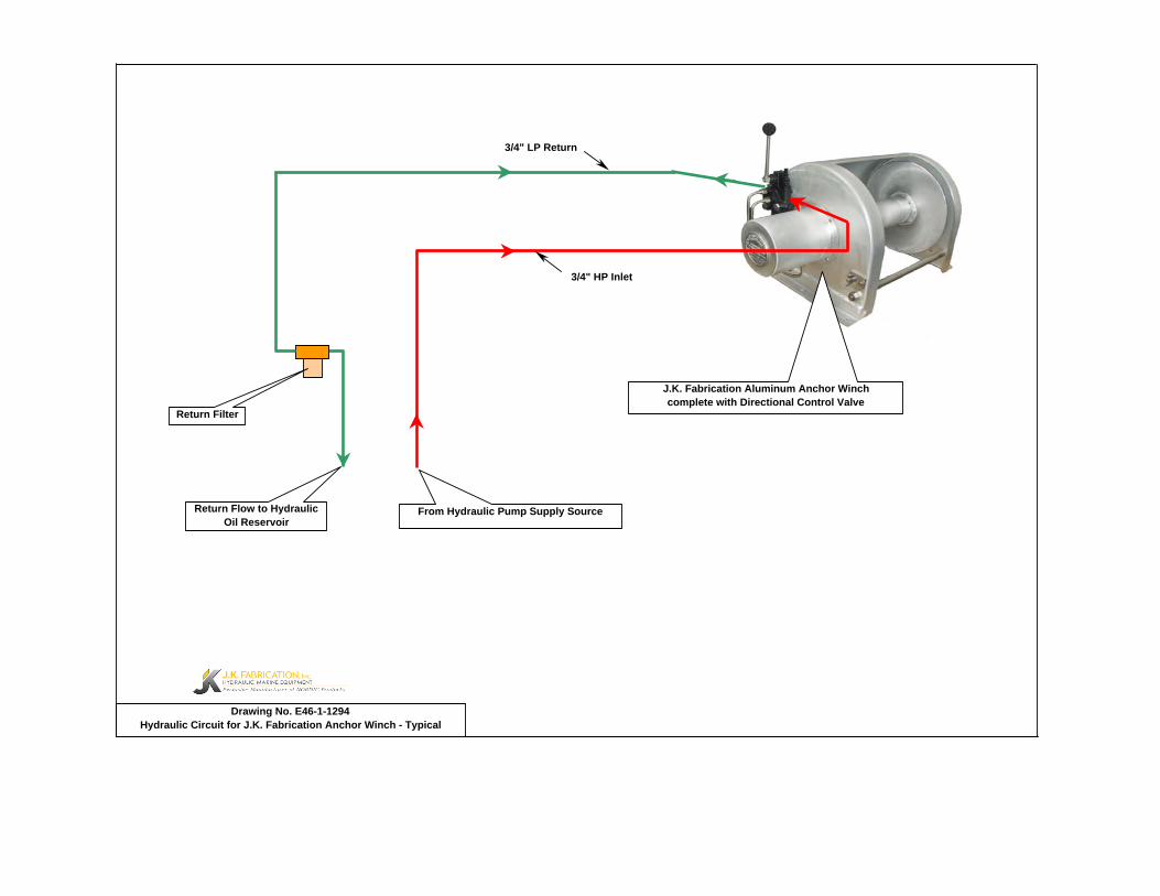
3/4" LP Return
3/4" HP Inlet
Drawing No. E46-1-1294Hydraulic Circuit for J.K. Fabrication Anchor Winch - Typical
Return Filter
J.K. Fabrication Aluminum Anchor Winch complete with Directional Control Valve
From Hydraulic Pump Supply SourceReturn Flow to Hydraulic Oil Reservoir

VENDOR DATA AND INFORMATION
For Service and Parts Assistance, Please Contact:
3101 West Commodore Way #3 Seattle, WA. 98199 USA
Phone: 206-297-7400 Fax: 206-297-1300
E-Mail: [email protected]
Contents:
WHITE RE Hydraulic Motor Information
WALVOIL SD11 Directional Control Valve Information

���������������

DUST SEAL REAR THRUST BEARINGHOUSING SEAL FRONT HOUSING BEARING (1" WIDE)METAL BACKUP SHIM REAR HOUSING BEARING (.5" WIDE)HIGH PRESSURE SEAL FORWARD MANIFOLD (CCW OR "0")METAL BACKUP SHIM REVERSE MANIFOLD (CW OR "1")POLYAMIDE SEAL BALANCE PLATE (3 BALLS INCLD)SHAFT SEAL STEEL BALLREAR HOUSING SEAL ENDCOVERBODY SEALS (2) FRONT THRUST BEARINGENDCOVER SEAL DUST SEAL
1000 PSI RELIEF VALVE2000 PSI RELIEF VALVE3000 PSI RELIEF VALVE
SEAL CARRIER 1.00-20 UNEF SLOTTED NUTTHRUST WASHER 1.00-20 UNEF SOLID NUT
1.00-20 UNEF LOCK NUT
ROTORS, DRIVE LINKS AND SPACERS, AND BOLTSWHEN CHANGING MOTOR DISPLACEMENTS, A MATCHING ROTOR AND BOLT SET KIT MUST BE ORDERED. A NEW DRIVE LINK KIT MAY BE NECESSARY.DRIVE LINK SPACERS ARE INCLUDED IN DRIVE LINK KITS, BUT MAY ALSO BE ORDERED SEPERATELY BY USING THE DRIVE LINK SPACER KIT NUMBER.
HOUSING KITS (EXPLODED VIEW ITEM #15)STANDARD HOUSING KITS INCLUDE THE FRONT BEARING (#14) AND THE REAR BEARING (#16) INSTALLED IN THE HOUSING.
#F31- 4-HOLE W/O PILOT & RS 4-HOLE BOLT PTRN. #A58- 6-HOLE SAE "A" STYLE WITH 1/2" BSP.F#W38- WHEEL MOUNT WITH 1/2" BSP.F #W38- WHEEL MOUNT W/ RELIEF PORT W/ 1/2" BSP.F#A38- 4-HOLE SAE "A" STYLE WITH 1/2" BSP.F #A38- 4-HOLE SAE "A" W/ RLF. PRT & 1/2" BSP.F#W31- WHEEL MOUNT WITH 7/8" O-RING #W31- WHEEL MOUNT W/ RLF. PORT & 7/8" O-RING#A31- 4-HOLE SAE "A" STYLE WITH 7/8" O-RING #A31- 4-HOLE SAE "A" W/ VAL. CAVITY & 7/8" O-RING#A11- 2-HOLE SAE "A" STYLE WITH 7/8" O-RING #A51- 6-HOLE SAE "A" W/ VAL. CAVITY & 7/8" O-RING#A18- 2-HOLE SAE "A" STYLE WITH 1/2" BSP.F #A58- 6-HOLE SAE "A" W/ VAL. CAVITY & 1/2" BSP.F#A51- 6-HOLE SAE "A" STYLE WITH 7/8" O-RING
SHAFTS AND RELATED COMPONENTS KITSSHAFT KITS COME WITH RELATED SHAFT COMPONENTS (i.e. keys, nuts, etc.)TO ORDER INDIVIDUAL SHAFT COMPONENTS (i.e. keys, nuts, bolts, washers or wire rings) USE THE KIT NUMBER FOR EACH INDIVIDUAL PART.
#02- 6-B SPLINE#22- 1-1/4" TAPERED#20- 1-1/4" STRAIGHT#23- 14 TOOTH SPLINE#10- 1" STRAIGHT#12- 25MM STRAIGHT#24- 19 TOOTH SPLINE#21- 32MM STRAIGHT#19- 1" STRAIGHT EXTENDED#01- 13 TOOTH SPLINE#29- 12 TOOTH SPLINE (BK)#26- 1-1/4" STR. NON-ANNEALE
Rev. 1.04
500133623500133723500133823500134823500134923
---
------
500449201500449201
------
500449201500449201
------------
---------
------
500449302---
------
---
------
------
---500449103500449100
---500449301
------
------
500018076
30WASHER KIT
KITS LIST
500131623500131723500131823
500449101
500445006500445006500445012500445014
500445024
500018076---
500018076---
500445014500445018500445026
ABOVE
500449303300339303P
500018077
BOLT SET KIT
NOT SHOWN
DRIVE LINK SPACER KIT
NOT SHOWN
---500018075
500018221500449304
NOT SHOWN
500018059500018003500018002500015006
SEE MISC.500449102
---500449100
BOLT KITNOT SHOWN
NUT KIT---
28KEY KIT
---
29WIRE RING KIT
10
12
500607011
500357005500407011
31EXPLODED VIEW ITEM #
500445026500445032
9
ITEMS # 1-10
SEAL KIT
678
EXP VIEWITEM #
12345
INCLUDED INSEAL KIT
INCLUDED IN
500444002
SEAL KIT500444001
ITEMS #11-12
500445045
500130523
HOUSING KIT500130223
HOUSING KIT
500018078
500131923500133523
DESCRIPTION
500014008
STANDARD ROTOR KIT FREETURN ROTOR KIT
500444003
11
375470540
DESCRIPTION
ITEMS # 1-12INCLUDED IN
KIT #
500014008500014008
500011600
500247005500207000500307005500357003500407005
27
DESCRIPTION
750
DESCRIPTION
500011300500011200
500087005 500087008500137005500167004
500137011500167011
500207004
500607005
26
500015007500012001500018048500016001500018252500018006500018228500018231
KIT
24
1NOT SHOWN
141619
13
1922
500307011
300
200
EXPLODED VIEW ITEM #DISPLACEMENT
120160
230260
350
SHAFT KIT
500130823
500130623500130723
500011109500011102 ---
500011101500011201
500449104
White Hydraulics, Inc. Phone (270) 885-1110 Fax (270) 886-8462
------------
500011203500011202500011114500011116500011214
500247011
500147004
500014009500014009
---
500018185
500014008500014008500014007
23
NOT SHOWN
20
NOT SHOWN
500147002500227000
18DRIVE LINK KIT
21
500014009500014009500014009500227004
21
RE (500) SERIES MOTOR COMPONENTSMISCELLANEOUS KITSSEAL KIT 500444001
DESCRIPTIONEXPLODED VIEW
ITEM #17

whitedriveproducts
White Drive Products, Inc. • P.O. Box 1127 • Hopkinsville, KY 42241 • Phone: 270.885.1110 • Fax: 270.886.8462
SERVICE INSTRUCTIONS FOR THE RE [500 & 501] SERIES MOTORS
PI444002 Rev. 12.06
For Use With Seal Kits: 500444001 & 500444002
dimensions: mm [in]
NOTE: IN DECEMBER 2006, THE 500 SERIES INCORPORATED A DESIGN CHANGE. THIS SET OF INSTRUCTIONS WILL AID IN THE DISASSEMBLY AND ASSEMBLY FOR BOTH DESIGNS. PLEASE REFER TO THE EXPLODED VIEW DRAWING TO DETERMINE WHICH DESIGN IS BEING REPAIRED AND THEN FOLLOW THE APPROPRIATE INSTRUCTIONS FOR THAT DESIGN.
Motor Section Disassembly (Same Instructions For Both Designs)Remove all shaft related components from shaft (27) (i.e. keys, wire rings, nuts). To aid in reassembly of the motor, make a "V" shaped set of lines from the endcover (24) to the housing using either paint or a marker. With shaft facing down, secure motor in vise by clamping on to housing (15).
Loosen and remove seven bolts (26) holding motor assembly together. Remove endcover (24) and endcover seal (10). Discard seal. Remove balance plate (22) taking care not to drop the three steel balls (23) located in the three holes in the balance plate (22). Remove rotor assembly (21), manifold (19), drive link spacer (20) (NOTE: Some motors do not use spacer), drive link (18) and thrust bearing (17). Remove body seals (9) from rotor assembly (21) and housing seal (8) from housing (15) and discard seals. (NOTE: Compare old housing seal (8) to the two housing seals included in kit to determine which one to use.) Gently tap shaft (27) upward from housing (15) and remove through rear of housing and lay aside.
Housing/Shaft Disassembly And Assembly (Design That Utilizes A Seal Carrier (11))Remove housing (15) from vise and turn over. Pry dust seal (1) from housing. Push the seal carrier (11), thrust washer (12) and thrust bearing (13) down until they make contact with the roller bearing (14) located in the housing bore.
Remove wire ring (2), steel backup shim (3) and high pressure seal (4) from inner bore groove with a small screwdriver. Lift seal carrier (11), thrust washer (12) and thrust bearing (13) from the housing bore. Using a small screwdriver, carefully pry shaft seal (7), backup seal (6), and metal backup shim (5) from seal carrier (11) and discard. Lay seal carrier (11), thrust washer (12) and thrust bearing (13) aside. (NOTE: If a new thrust washer (12) and seal carrier (11) is included in kit, old items may be discarded).
At this point, all parts should be cleaned in an oil-base solvent and dried using compressed air (For safety, observe all OSHA safety guidelines). All new seals should be lightly coated in clean oil prior to installation.
Place shaft (27) on a clean flat surface with output end facing up. Place thrust bearing (13) (NOTE: If thrust bearing has integral washer, make sure washer surface faces down.) Then thrust washer (12) on shaft (See Technical Bulletin PI444004 to determine correct thrust washer to use). Lightly coat seal area of shaft with clean oil and place plastic installation sleeve with shaft seal (7) down onto shaft covering all splines, keyways and wire ring grooves. Slide shaft seal (7) down onto shaft (27) making sure that lip on seal faces down (See Figure 1 for correct seal orientation) until it contacts thrust washer (12). Remove plastic installation sleeve. Carefully install the backup seal (6) onto the shaft (27) with the flat side up and the seal lip facing the shaft seal (7). Place the metal backup shim (5) onto the shaft and against the backup seal (6). Place the seal carrier (11) onto the shaft (large end down) and carefully press the seal carrier (11) down onto the seal assembly using an arbor press and sleeve to compress the seal into the carrier.
With pilot side facing up, place housing (15) on spacers to raise housing approximately 6 [.25] above work surface (NOTE: Spac-ers should allow shaft to contact work surface). Place shaft/seal carrier assembly into housing (15). Install high pressure seal (4) into groove in housing. Install metal backup shim (3) against high pressure seal (4) in groove in housing bore by squeezing the shim (3) between thumb and forefinger to bow shim. While maintaining bow in shim, start the shim into the groove and use a small screwdriver to push the shim into groove. Install wire ring (2) into the groove making sure that the ends are butted.
While holding shaft into housing, place housing/shaft assembly in vise with shaft end down. Making sure that end of drive link (18) with crowned splines goes into shaft end, install drive link (18) into shaft and tap lightly to seat the seal carrier against the wire ring (2). Place thrust bearing (17) over drive link (18). If seal carrier (11) is properly seated against wire ring (2), thrust bearing (17) will be flush with rear surface of housing.
Housing/Shaft Disassembly And Assembly (Design That Does NOT Utilizes A Seal Carrier (11))Position the housing (15) in vise and use a slide and hammer type bearing puller to remove the rear housing bearing (16), the bearing spacer (32), and the front housing bearing (14). Remove the thrust washer (12) and thrust bearing (13) and set aside. Us-ing a small screwdriver carefully pry the shaft seal (7), backup seal (6) and metal shim (5) from housing bore and discard.
Remove the housing from vise and turn over and pry the dust seal (1) from housing and discard.
At this point, all parts should be cleaned in an oil-base solvent and dried using compressed air (For safety, observe all OSHA safety guidelines). All new seals should be lightly coated in clean oil prior to installation.
Place housing (15) in vice with the seven bolt assembly holes facing up. Place metal shim (5) in the smallest diameter recess in
A)
B)
C)
D)
E)
F)
G)
H)
I)
J)

White Drive Products, Inc. • P.O. Box 1127 • Hopkinsville, KY 42241 • Phone: 270.885.1110 • Fax: 270.886.8462
FIGURE 1
BACKUP SEALSEAL CARRIERMETAL BACKUP SHIM
SHAFT SEALMETAL BACKUP SHIMHIGH PRESSURE SEALWIRE RING
FIGURE 2
1
2
3
4
5
6
7
1. *† Dust Seal2. *† Split Wire Ring3. *† Metal Backup Shim4. *† High Pressure Seal5. *† Metal Backup Shim6. *† Backup Seal (2)7. *† Shaft Seal (2)8. *† Housing Seal9. *† Body Seals (2)10. *† Endcover Seal11. * Seal Carrier12. * Thrust Washer
BACKUP SEALHOUSING
SHAFT SEALMETAL BACKUP SHIM
FIGURE 3
the housing (15). Install the backup seal (6) into the housing (15) with the flat side down and the seal lip facing up. Insert shaft seal (7) down into housing (15) making sure that lip on seal faces up (See Figure 2 for correct seal orientation). Install thrust washer (12) into housing and using an arbor press, seat the shaft seal (7) into housing (15), then place the thrust bearing (13) into housing.
Place front housing bearing (14) onto housing and press bearing into housing to a depth of 60,1 [2.37] from the rear surface of the housing (15) to the top of the bearing. Insert the bearing spacer (32) into the housing. Place the rear housing bearing (16) onto the rear housing bore and press to a depth of 3,6 [.14] from the rear surface of the housing (15) to the top of the bearing (16). Place the shaft (27) down into housing (15) and place thrust bearing (17) on top of shaft (27). If shaft seals are properly seated against the housing (15), thrust bearing (17) will be flush with rear surface of housing.
Motor Section Assembly (Same Instructions For Both Designs)Install housing seal (8) into groove in housing (15). Place manifold (19) onto housing, (15) side with only seven holes facing housing (15). Place body seals (9) in grooves in both sides of rotor (21). Place rotor (21) onto manifold (19) with side of rotor with chamfer in splines facing manifold (19).
Install balance plate (22) onto rotor (21) making sure holes for steel balls (23) faces up. Install three steel balls (23) in holes in bal-ance plate (22). Install endcover seal (10) into groove in endcover (24) and place endcover onto balance plate (22). Install seven assembly bolts (26) and pre-torque to 13,6 Nm [10 ft. lbs.] Using the bolt torque sequence shown in Figure 3, final torque all bolts to 67,8 Nm [50 ft. lbs.]
Remove motor from vise and place on work surface with shaft (27) facing up. Making sure that lip on seal (1) faces up, place dust seal (1) over shaft (27). Using a sleeve and a hammer, carefully drive dust seal (1) into place.
K)
L)
M)
N)
O)
13. Front Thrust Bearing 14. Front Housing Bearing15. Housing16. Rear Housing Bearing17. Rear Thrust Bearing18. Drive Link19. Manifold 20. Drive Link Spacer21. Rotor Assembly22. Balance Plate23. Steel Balls (3)24. Endcover
25. I.D. Tag Assembly26. Assembly Bolts (7)27. Shaft28. Shaft Key29. Shaft Bolt30. Lock Washer31. Wire Ring32. Bearing Spacer
* Contained in Seal Kit 500444001† Contained in Seal Kit 500444002
EXPLODED VIEW PARTS DESCRIPTION
NOTE: The motor design that utilizes a seal carrier will use the larger O.D. backup seal and shaft seal.

White Drive Products, Inc. • P.O. Box 1127 • Hopkinsville, KY 42241 • Phone: 270.885.1110 • Fax: 270.886.8462
8
9
10
18
19
21
22
23
24
26
25
20
13
1
7
5
6
12
14
16
15
32
27
28
3129
30
17
1
6
3
11
12
14
17
15
27
3129
30
2
4
2
7
1328
16
500 SERIES MOTOR DESIGN UTILIZING SEAL CARRIER
500 SERIES MOTOR DESIGN WITHOUT SEAL CARRIER

SD11
DAT004A2
Features
1st edition June 2006:
Questa edizione aggiorna tutte le precedenti.
WARNING!
All specifications of this catalog refer to the standard product at this date.
Walvoil, oriented to a continuous improvement, reserves the right to
discontinue, modify or revise the specifications, without notice.
WALVOIL IS NOT RESPONSIBLE FOR ANY DAMAGE CAUSED BY AN
INCORRECT USE OF THE PRODUCT.
Additional information
This catalog shows the product in the most standard configurations.
Please contact Sales Dpt. for more detailed information or special request.
Simple, compact and heavy duty designed monoblock valves from 1 to 6 sections for open and closed centre hydraulic systems.
H Fitted with a main pressure relief valve and a load check valve.
H Available with parallel or series circuit.
H Optional power beyonf port (only for parallel circuit).
H Diameter 20 mm -- 0.79 in interchangeable spools.
H A wide variety of service ports and circuit valves.
H Available manual, pneumatic, hydraulic, electro--hydraulic and remote with flexible cables spool control kits.
SD11
DAT004A 3
Content
ContentWorking conditions 4. . . . . . . . . . . . . . . . . . . . . . . . . . . . . . . . .
Dimensional data 5. . . . . . . . . . . . . . . . . . . . . . . . . . . . . . . . . . .
Hydraulic circuit 6. . . . . . . . . . . . . . . . . . . . . . . . . . . . . . . . . . . .
Performance data 7. . . . . . . . . . . . . . . . . . . . . . . . . . . . . . . . . .
Ordering codes 8. . . . . . . . . . . . . . . . . . . . . . . . . . . . . . . . . . . . .
Inlet relief options 10. . . . . . . . . . . . . . . . . . . . . . . . . . . . . . . . . .
Spools 13. . . . . . . . . . . . . . . . . . . . . . . . . . . . . . . . . . . . . . . . . . .
“A” spool positioners 20. . . . . . . . . . . . . . . . . . . . . . . . . . . . . . .
“B” side options 36. . . . . . . . . . . . . . . . . . . . . . . . . . . . . . . . . . .
Complete controls 41. . . . . . . . . . . . . . . . . . . . . . . . . . . . . . . . .
Outlet port options 45. . . . . . . . . . . . . . . . . . . . . . . . . . . . . . . . .
Service and auxiliary valves 48. . . . . . . . . . . . . . . . . . . . . . . . .
ordering codes 48. . . . . . . . . . . . . . . . . . . . . . . . . . . . . . . . .
port relief valves 49. . . . . . . . . . . . . . . . . . . . . . . . . . . . . . . .
anti--shock valves with cross return 50. . . . . . . . . . . . . . .
pilot check valves 51. . . . . . . . . . . . . . . . . . . . . . . . . . . . . .
anti--shock and anti--cavitation valves 55. . . . . . . . . . . . .
Other executions
SD11/1--N directional valve 60. . . . . . . . . . . . . . . . . . . . . .
SD11--S directional valve with series circuit 61. . . . . . . . .
Installation and maintenance 63. . . . . . . . . . . . . . . . . . . . . . . .
Accessories 65. . . . . . . . . . . . . . . . . . . . . . . . . . . . . . . . . . . . . .

Working conditions
Filettature standard
SD11
DAT004A4
This catalog shows technical specifications and diagrams measured with mineral oil of 46 mm2/s -- 46 cSt viscosity at 40°C -- 104°F
temperature.
Nominal flow rating 70 l/min 18 US gpm
Operating pressure (maximum) parallel circuit 315 bar 4600 psip g p ( )
series circuit 250 bar 3600 psi
Max. back pressure on outlet T 25 bar 360 psi
Internal leakage A(B)→T ∆p=100 bar -- 1450 psifluid and valve at 40°C − 104°F 3 cm3/min 0.18 in3/min
Fluid Mineral base oil
Fluid temperature with NBR seals from --20°C to 80°C from --4°F to 176°F
with FPM (VITON) seals from --20°C to 100°C from --4°F to 212°F
Viscosity campo di lavoro from 15 to 75 mm2/s from 15 to 75 cSty
minima 12 mm2/s 12 mm2/s
massima 400 mm2/s 400 mm2/s
Max level of contamination --/19/16 -- ISO 4406 19/16 -- ISO 4406
Ambient temperature forwith mechanical control from --40°C to 60°C from --40°F to 140°F
Ambient temperature forworking conditions with hydraulic, pneumatic controls from --30°C to 60°C from --22°F to 140°Fworking conditions
with electric controls from --20°C to 50°C from --4°F to 122°F
NOTE -- For different conditions please contact Sales Dept.
REFERENCE STANDARDS
BSP UN--UNF METRIC NPTF
THREADACCORDING TO
ISO 228/1 ISO 263 ISO 262 ANSI B1.20.3ACCORDING TO BS 2779 ANSI B1.1 unified
CAVITYACCORDING TO
ISO 1179 11926 9974--1ACCORDING TO SAE J1926 J476a
DIN 3852--2shape X or Y
3852--1shape X or Y
PORTS THREAD
MAIN PORTS BSP UN--UNF METRIC
IInlet P and power beyond C G 1/2 7/8--14 (SAE 10) M18x1.5
Ports A and B G 1/2 3/4--16 (SAE 8) M18x1.5
Outlet T G 3/4 7/8--14 (SAE 10) M22x1.5
CONTROL PILOT PORTS
Pneumatic NPTF 1/8--27 NPTF 1/8--27 NPTF 1/8--27
Hydraulic G 1/4 9/16--18 (SAE 6) G 1/4

SD11
DAT004A 5
TYPEE F Weight
TYPEE F Weight
TYPEmm in mm in kg lb
TYPEmm in mm in kg lb
SD11/1--P 130 5.12 100 3.94 6.1 13.4 SD11/4--P 264.5 10.41 235 9.25 14.2 31.3
SD11/2--P 174.5 6.87 145 5.71 8.8 19.4 SD11/5--P 309.5 12.19 280 11.02 16.7 36.8
SD11/3--P 219.5 8.64 190 7.48 11.4 25.1 SD11/6--P 354.5 13.96 325 12.80 19.4 42.8
Dimensional data (parallel circuit)
WALVOILSD11/2--PP0600001104219001
MADE IN ITALYValve code
Production batch :P06 = production year (2006)00001 = progressive number
Valve type
243.
5 125
62.5
36
51
17.5F
E
29.5 38 45 35
69.5
103
67.5
36
11
P
T
8.5
25
70
102.5
∅1
2
0
WA
LVO
ILS
D11
/2--P
P06
0000
110
4219
001
MA
DE
INIT
ALY
M 10
54
spool out3
3spool in
24
2.5
M10
2.50.098
0.69
2.01
4.92 1.
422.
46
9.59
1.16 1.50 1.77 1.34
4.06
2.74
0.43
1.42
2.66
0.33
4.04
0.94
0.98
2.13
2.76Power
beyond24
0.94

T
P
A
B
Parallel
Hydraulic circuit
Standard configuration with side inlet and open center circuit (AET configuration).
Main relief valve
Lever box
Load check valveAllen wrench 4
24 Nm / 17.7 lbft
Top inlet and outlet configuration
PA1 B1 A2 B2
T
Description example:SD11/2--P(JG3--120)/18L/18L/AET--PSA--SAE
120
P
A1 B1 A2 B2
T
Description example:SD11/2--P(JG3--120)/18L/18L/AET--SAE
120
Standard configuration
Pressure line
”A” port line
”B” port line
Positioner kit
Open center plugAllen wrench 8
24 Nm / 17.7 lbft
17501750
Outlet line
Flow throught (LC)
SD11
DAT004A6
Work port to outlet
Inlet to work port
Open center
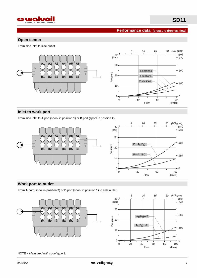
Performance data (pressure drop vs. flow)
0
10
20
30
40
0 30 60 90
0
10
20
30
40
0 30 60 90
Flow
Pre
ssur
e
0
10
20
30
40
0 20 40 60 80 100
From side inlet to side outlet.
From side inlet to A port (spool in position 1) or B port (spool in position 2).
From A port (spool in position 2) or B port (spool in position 1) to side outlet.
NOTE -- Measured with spool type 1.
(l/min)
(bar)
Flow
Pre
ssur
e
(l/min)
(bar)
Flow
Pre
ssur
e
(l/min)
(bar)
A1 A2 A3
B1 B2 B3
P
T
A4 A5 A6
B4 B5 B6
A1 A2 A3
B1 B2 B3
P
T
A4 A5 A6
B4 B5 B6
A1 A2 A3
B1 B2 B3
P
T
A4 A5 A6
B4 B5 B6
2 sections
4 sections
6 sections
P→A6(B6)
P→A1(B1)
A6(B6)→T
A1(B1)→T
540
360
180
(psi)
0
540
360
180
(psi)
0
540
360
180
(psi)
0
5 10 (US gpm)15 20
5 10 (US gpm)15 20
5 10 (US gpm)15 20
SD11
DAT004A 7

SD11
DAT004A8
Ordering codes5.
1.
SD11 / 2 -- P (KG3--120) / 1 8 L / 18L . P3(G3--120) / AET -- PSL -- SAE *
2. 3. 4. 5.
1st sectionfollowingsection
1.
I
Main relief valvesetting (bar)
Description example:
II
7.
2.
3.
5.
7.
8.
8.
2. Inlet reliaf options page 10Standard setting is referred to 10 l/min / 2.6 US gpm flow.TYPE CODE DESCRIPTIONSV XTAP526340 Valve blanking plugVMD10/1: direct differential pressure relief valve type K (standard)(KG2--80) 5KIT110112 Range 20 to 63 bar / 290 to 900 psi
standard setting 40 bar / 580 psi(KG3--120) 5KIT110113 Range 63 to 200 bar / 900 to 2900 psi
taratura standard 120 bar / 1750 psi(KG4--220) 5KIT110114 Range 180 to 315 bar / 2600 to 4600 psi
standard setting 220 bar / 3200 psiVMD10/1: direct pressure relief valve type Y(YG1--80) 3XCAR110211 Range 63 to 125 bar / 900 to 1800 psi
standard setting 80 bar / 1150 psi(YG2--125) 3XCAR110212 Range100 to 160 bar / 1450 to 2300 psi
tandard setting 125 bar / 1800 psi(YG3--175) 3XCAR110213 Range 125 to 250 / 1800 to 3600 psi
standard setting 175 bar / 2500 psi(YG4--220) 3XCAR110214 Range 200 to 315 / 2900 to 4600 psi
standard setting 220 bar / 3200 psiVMP10/1: pilot pressure relief valve type X(XG--125) X006211120 Range 25 to 315 bar / 360 to 4600 psi
standard setting 120 bar / 1750 psi
6.
Port valve setting (bar)
6.
8.
4.
1. Body kit *TYPE CODE DESCRIPTION1--P 5KC1417000 Parallel, 1 section2--P 5KC1427000 Parallel, 2 sections3--P 5KC1447000 Parallel, 3 sections4--P 5KC1477000 Parallel, 4 sections5--P 5KC1517000 Parallel, 5 sections6--P 5KC1547000 Parallel, 6 sections
Include body, seals, rings and load check valves.
9.
9.
Service valves page 48Port relief valves, pilot check valves,antishock valves, anticavitation valvesand combined.
NOTE (*) -- Items are referred to UN- UNF thread.

SD11
DAT004A 9
4. “A” side spool positioners page 20TYPE CODE DESCRIPTION7FC 5V07310000 With friction and neutral position sensor8 5V08110000 With spring return in neutral position8D 5V08110200 With spring return in neutral position and pin
with M6 female thread for dual control8D1 5V08110210 With spring return in neutral position and pin
with ∅ 8mm (0.32in) radial hole8D2 5V08110220 With spring return in neutral position and pin
with M8 male thread for dual control8TL 5V08110310 Come tipo 8, per comando a cavo flessibile8F2 5V08110101 Come tipo 8 con limitatore di corsa regolabile8M3 5V08110400 Come tipo 8 con perno uscente per comando
microinterruttore in posizione 1 e 219 5V19110000 2 positions, with spring return in neutral
position from position 120 5V19110000 2 positions, with spring return in neutral
position from position 211 5V11110000 Detent in positions neutral, 1 and 212 5V12110000 Detent in positions 1 and 215 5V15110000 2 positions, detent in positions 1 and neutral16 5V16110000 2 positions, detent in positions 2 and neutral21 5V21110000 Aggancio in pos. 2 e ritorno a molla in pos. 19B 5V09110000 With detent in position 1 and spring return in
neutral position10B 5V09110000 With detent in position 2 and spring return in
neutral position11B 5V11210000 Detent in positions 1 and 2 and spring return in
neutral position8MG3 5V08110050 As type 8 and microswitch in positions 1 and 28K 5V08710112 As type 8 and 12 VDC solenoid lock device
5V08710124 As previous, 24 VDC8P 5V08110701 ON/OFF pneumatic kit8PG 5V08111706 Proportional pneumatic kit8EPG3 5V08111725 12 VDC ON/OFF electropneumatic kit
5V08111726 24 VDC ON/OFF electropneumatic kit8ID3 5V08111801 Proportional hydraulic kit8EI3 5V08110350 12 VDC ON/OFF electrohydraulic kit
5V08110351 24 VDC ON/OFF electrohydraulic kitSpecial positioners for particular spools page 27. . . . . . . . . . . . . . . . . .9A 5V09511000 With detent in position 1, automatic release in
neutral position11A 5V11511000 With detent in position 1 and 2, automatic
release in neutral positionParticular positioner kits for special spools pag. 33. . . . . . . . . . . . . . .13B 5V13111000 4 pos. with spring return in neutral pos. and
detent in 4th pos.: for spool 513C 5V13211000 4 pos. with spring return in neutral pos. and
detent in 4th pos.: for spool 5VR8MCCR 5V08210021 Spring return in neutral position, with reduced
spool stroke: for spool 8F13FZ1 5V13611100 4 pos. with spring return in neutral pos. and
detent in 2nd pos.: for spool 88. Inlet and outlet selection * page 6
7. Outlet port options page 45
5. “B” side options page 36
Ordering codes
TYPE CODE DESCRIPTIONL 5LEV110000 Standard lever boxLF1 5LEV110101 Lever box with adjustable flow limiterLS 5LEV110020 Waterproof lever boxLB 5LEV310000 Steel leverLEB 5LEV610000 Safety lever boxSLP 5COP110000 Without lever box, with dust--proof plateTQ 5TEL110110 CD flexible cable connectionLCB 5CLO211100 Joystick lever for 2 sections operation
TYPE CODE DESCRIPTIONAET 3XTAP732201 Open center plugAEK 3XTAP532450 Closed center plug
AE 3XGIU532660* SAE10 power beyond sleeve
AET--EL 5CAR411312 With 12VDC electric control unloadervalve; normally open circuit
5CAR411314 As previous 24VDC
TYPE CODE DESCRIPTIONPSL 3XTAP826160 SAE10 plug for upper inlet and outlet (nr.2
request): side ports openPSA 3XTAP826160 SAE10 plug for side inlet and outlet (nr.2
request): upper ports open
3. Spool options page 13TYPE CODE DESCRIPTION1 3CU1410130 Double acting, 3 positions, with A and B
closed in neutral position1A 3CU1421130 Double acting, 3 positions, with A open to
tank in neutral position1B 3CU1422130 Double acting, 3 positions, with B open to
tank in neutral position2 3CU1425130 Double acting, 3 positions, with A and B
open to tank in neutral position3 3CU1431130 Single acting on A, 3 positions, B plugged
requires G3/8 plug (see part I )4 3CU1435130 Single acting on B, 3 positions, A plugged
requires G3/8 plug (see part I )Special spools for particular positioner kits page 16. . . . . . . . . . . . . .5 3CU1442100 Double acting, 4 positions, floating circuit
in 4th position with spool in5VR 3CU1443610 Double acting, 4 positions, floating circuit
in 4th position with spool out, with checkvalve
8 3CU1462110 Doppio effetto, 4 pos., rigenerativo in 4a
posizione con cursore a entrare8F 3CU1461100 Double acting, 4 positions, regenerative
circuit in 4th position with spool inSpecial spools for standard positioner kits page 33. . . . . . . . . . . . . . .1(9A) 3CU1410300 Double acting, 3 positions, with A and B
closed in neutral pos: for 9A positioner1(11A) 3CU1410320 Double acting, 3 positions, with A and B
closed in neutral pos: for 11A positioner
9. Complete controls page 41Proportional hydraulic control type 8IM and rotative control type R.
I ”A” and “B” ports plugs *TYPE CODE DESCRIPTIONSAE8 3XTAP822150 For single acting spools type 3 and 4
II Optional handleversTYPE CODE DESCRIPTIONAL01/M10x200 170012020 For lever L: height 200 mm / 7.87 inAL08/M12x250 170013125 For joystick LCB: height 250 mm / 9.84 in

0
100
200
300
400
0 20 40 60 80
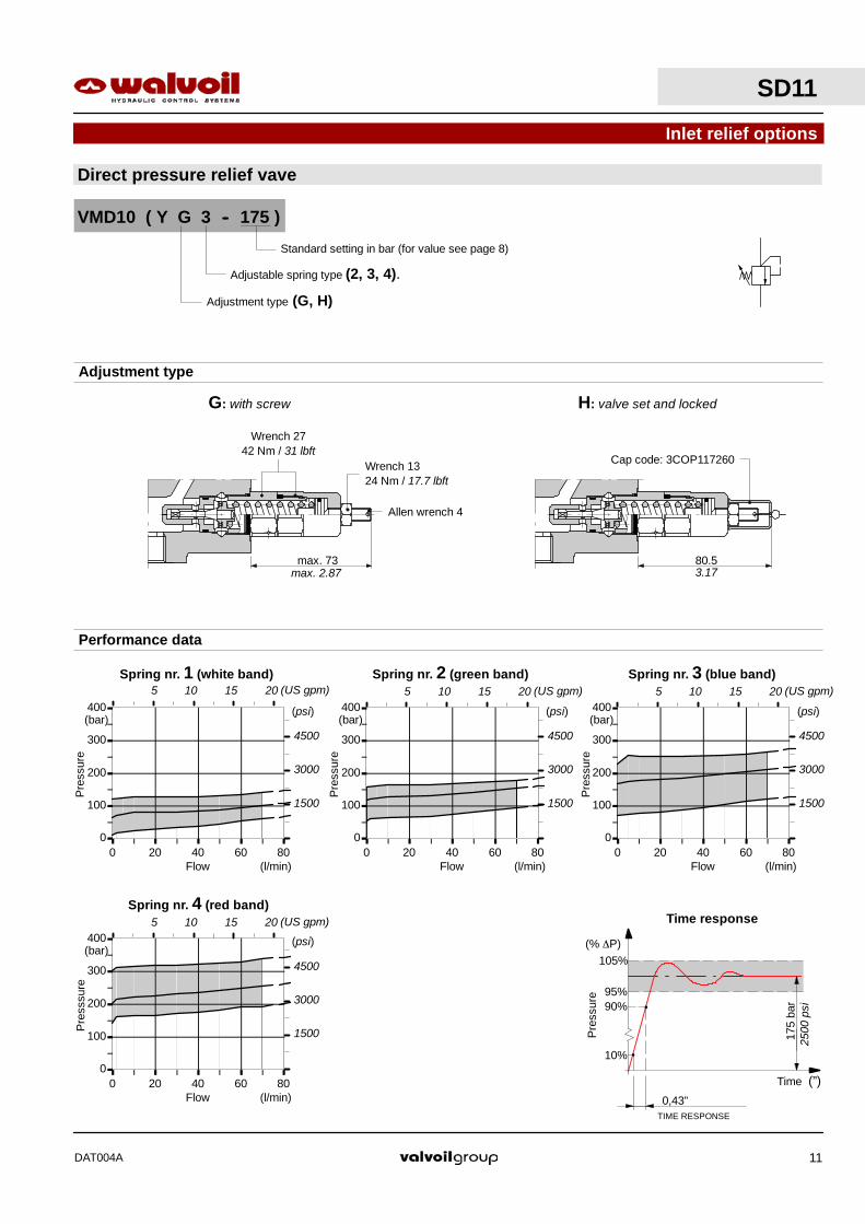
Direct differential pressure relief vave
Inlet relief options
VMD10 ( K G 3 -- 120 )
Standard setting in bar (for value see page 8)
Adjustment type
Adjustment type (G, H)
Adjustable spring type (2, 3, 4).
G: with screw H: valve set and locked
66.5max. 61
Wrenc 27 -- 42 Nm / 31 lbft
Allen wrench 4
Cap code: 3COP117260Wrench 1324 Nm / 17.7 lbft
max. 2.40 2.62
0
100
200
300
400
0 20 40 60 80
Spring nr. 4 (red band)
Spring nr. 3 (blue band)Spring nr. 2 (green band)
0
100
200
300
400
0 20 40 60 80
Flow
Pre
ssur
e
(l/min)
(bar)
Flow
Pre
ssur
e
(l/min)
(bar)
Flow
Pre
ssur
e
(l/min)
(bar)
0,2”TIME RESPONSE
10%
120
bar90%
95%
105%
Pre
ssur
e
Time (”)
(% ∆P)
Time response
Performance data
(psi)
4500
3000
1500
(psi)
4500
3000
1500
(psi)
4500
3000
1500 1750
psi
5 10 15 20 (US gpm) 5 10 15 20 (US gpm)
5 10 15 20 (US gpm)
SD11
DAT004A10
0
100
200
300
400
0 20 40 60 80
Direct pressure relief vave
Inlet relief options
Spring nr. 4 (red band)
Spring nr. 3 (blue band)Spring nr. 2 (green band)
0
100
200
300
400
0 20 40 60 80
0
100
200
300
400
0 20 40 60 80Flow
Pre
ssur
e
(l/min)
(bar)
Flow
Pre
ssur
e
(l/min)
(bar)
Flow
Pre
sssu
re
(l/min)
(bar)
0,43”TIME RESPONSE
10%
175
bar90%
95%
105%
Pre
ssur
e
Time (”)
(% ∆P)
Time response
VMD10 ( Y G 3 -- 175 )
Standard setting in bar (for value see page 8)
Performance data
Adjustment type
Adjustment type (G, H)
Adjustable spring type (2, 3, 4).
G: with screw H: valve set and locked
Cap code: 3COP117260
max. 73 80.5
Wrench 1324 Nm / 17.7 lbft
Wrench 2742 Nm / 31 lbft
Allen wrench 4
0
100
200
300
400
0 20 40 60 80
Spring nr. 1 (white band)
Flow
Pre
ssur
e
(l/min)
(bar)
max. 2.87 3.17
(psi)
4500
3000
1500
(psi)
4500
3000
1500
(psi)
4500
3000
1500
(psi)
4500
3000
1500
2500
psi
5 10 15 20 (US gpm) 5 10 15 20 (US gpm) 5 10 15 20 (US gpm)
5 10 15 20 (US gpm)
SD11
DAT004A 11

0
5
10
15
0 30 60 90
Flow
Pre
ssur
e
(l/min)
(bar)
P→T
A(B)→T
Pressure drop
P
A1 B1
T
1201750
Dimensional data
Hydraulic circuit Performance data
Description axample:
SD11/1--N(KG3--120)/18L--SAE -- Code: 104119001
69.5
103
11
125
36
353830
62.5
51.5
243.
5
12.5 100
130
M10
51
15.5
70
54
8.5
25
102.5
16°
16°
1
2
0
29°
spool out3
27°30’
3spool in
P→A(B)
3.94
5.12
0.49
2.03
2.46
9.59
2.01
0.61
2.74
4.06 4.
921.
420.43
1.18 1.5035
1.38
0.33
2.76
2.13
4.04
0.98
(psi)
150
100
50
200
5 10 (US gpm)15 20
SD11/1--N
DAT004A60
Standard threads
PORTS BSP(ISO228/1)
UN--UNF(ISO 11926--1)
METRIC(ISO 262)
Inlet P G 1/2 7/8--14 UNF--2B (SAE 10) M18x1.5
Ports A and B G 1/2 3/4--16 UNF--2B (SAE 8) M18x1.5
Outlet T G 3/4 7/8--14 UNF--2B (SAE 10) M22x1.5

Installation and maintenance
The SD11 valve is assembled and tested as per the technical specification of this catalogue.
Before the final installation on your equipment, follow the below recommendations:
-- the valve can be assembled in any position, in order to prevent body deformation and spool sticking mount the product on a flat
surface;
-- in order to prevent the possibility of water entering the lever box and spool control kit, do not use high pressure wash down directly
on the valve;
-- prior to painting, ensure plastic port plugs are tightly in place.
NOTE -- These torque are recommended. Assembly tightening torque depends on many factors, including lubrication, coating andsurface finish. The manufacturer shall be consulted.
P
C
A1A2
B2
TB1
Directional valve with poer beyond configuration
SD11
DAT004A 63
Fittings tightening torque -- Nm / lbft
THREADS TYPE P and C ports A and B ports T port
BSP (ISO 228/1) G 1/2 G 1/2 G 3/4
With O--Ring seal 50 / 37 50 / 37 70 / 51.6
With copper washer 60 / 44.3 60 / 44.3 70 / 51.6
With steel and rubber washer 60 / 44.3 60 / 44.3 70 / 51.6
UN--UNF (ISO 11926--1) 7/8--14 UNF--2B (SAE 10) 3/4--16 UNF--2B (SAE 8) 7/8--14 UNF--2B (SAE 10)
With O--Ring seal 60 / 44.3 50 / 37 60 / 44.3
METRICA (ISO 262) M18x1.5 M18x1.5 M22x1.5
With O--Ring seal 35 / 25.8 35 / 25.8 50 / 37
With copper washer 40 / 29.5 40 / 29.5 60 / 44.3
With steel and rubber washer 40 / 29.5 40 / 29.5 60 / 44.3

Installation and maintenance
NOTE -- All articulated parts inside cap, lever box and mechanical joystick are lubricated with synthetic base grease grade NLGI2
1) Directional valve body2) Main relief valve3) Spool: normally the spools are inter--
changeable. Verify the smoothnessduring the assembly
4) Lever box5) Side “A” spool positioner6) Load check valve7) Holding O--Ring bushing8) O--Ring seal 18x2,5
code: 4GUA120235
Item list
Sealing edge
Ring chamfer
SD11
DAT004A64
Malfunction Cause Remedy
External leakage pivot box lever orcontrol kit side.
Worn spool seal due to mechanicalactuation or high back pressure.
Locate the leakage and replace the seal.Check back pressure level.
Excessive internal leakage on A and Bports.
Increase clearance between spools andbody due to high wear.
Replace the directional control valve andcheck the oil contamination level.
Dropping load during transition whileraising. High leakage on the load check valve Remove the load check valve and clean
the seat, verifing it’s not dented.
Inability to build pressure on A and B Pressure relief valve blocked open. Remove and clean or replace the valve.Inability to build pressure on A and Bports. Low pump pressure and flow. Check the pump and circuit.

3101 West Commodore Way #3
Seattle, WA 98199 Telephone 206-297-7400
Fax 206-297-1300 [email protected]
LIMITED WARRANTY
J. K. Fabrication, Inc. warrants each new Product to be free from defects in Material and Workmanship for a period of one (1) Year from date of shipment by J. K. Fabrication, Inc.’s factory when properly installed and maintained in an application consistent with its intended normal use. No product will be eligible for warranty due to lack of lubrication in the assemblies, or from neglect from maintaining proper lubrication in the assemblies. Otherwise, should any product be found under normal use and service during the warranty period to be defective, J. K. Fabrication, Inc. will, at its option, repair or replace such product F.O.B. Seattle, Washington, USA, provided such product is returned to the location designated by J. K. Fabrication, Inc., Freight Prepaid, and inspection by J. K. Fabrication, Inc. establishes the defect to the satisfaction of J. K. Fabrication, Inc. Any replacement provided under this warranty will be warranted for the remainder of the warranty period applicable to the product in which it is installed or which it replaces. This warranty shall not apply to a product upon which repairs or alterations have been made, unless authorized by J. K. Fabrication, Inc., or to a product which has been misused, neglected, improperly maintained, improperly lubricated, incorrectly installed or used beyond the limits of the product rating; nor shall this warranty apply to any product manufactured in accordance with specifications of the buyer, and J. K. Fabrication, Inc. shall have no responsibility or liability for such product. Buyer’s remedy under this warranty is exclusive and is limited to repair or replacement as provided herein. J. K. Fabrication, Inc. shall not in any event be liable for consequential or incidental damages, regardless of whether such damages arise from contract or tort, including negligence, nor shall J. K. Fabrication, Inc. be held liable for any expenses, lost incomes, attorneys’ fees or delay caused by defective material or workmanship. No allowance will be made for repairs, replacements or alterations unless made with the written consent of J. K. Fabrication, Inc. This warranty is expressly in lieu of any other warranties, whether written or oral, express or implied, including any warranty of merchantability or fitness for a particular purpose.
WARNING J.K. Fabrication, Inc. Winches and Products are not designed, nor are they to be used, for operations involving the lifting or moving of personnel. J.K. Fabrication, Inc. will not be held liable responsible for any accident resulting from such use.
Effective August 2008