owner’s manual model year 2013 edition: january …...the engine cooling fans may run after the...
TRANSCRIPT

0 - 1Owner’s Manual Model Year 2013 Edition: January 2013 KTA-2648/7-VX-enVAUXHALL Antara
Owner’s Manual Model Year 2013 Edition: January 2013 KTA-2648/7-VX-en

Introduction .................................... 2In brief ............................................ 6Keys, doors and windows ............ 18Seats, restraints ........................... 33Storage ........................................ 53Instruments and controls ............. 72Lighting ...................................... 105Climate control ........................... 114Driving and operating ................. 121Vehicle care ............................... 149Service and maintenance .......... 191Technical data ........................... 194Customer information ................ 206Index .......................................... 208
Contents

2 Introduction
Introduction

Introduction 3
Vehicle specific dataPlease enter your vehicle's data onthe previous page to keep it easilyaccessible. This information isavailable in the sections "Service andmaintenance" and "Technical data"as well as on the identification plate.
IntroductionYour vehicle is a designedcombination of advanced technology,safety, environmental friendlinessand economy.This Owner's Manual provides youwith all the necessary information toenable you to drive your vehiclesafely and efficiently.Make sure your passengers areaware of the possible risk of accidentand injury which may result fromimproper use of the vehicle.You must always comply with thespecific laws and regulations of thecountry that you are in. These lawsmay differ from the information in thisOwner's Manual.
When this Owner's Manual refers to aworkshop visit, we recommend yourVauxhall Authorised Repairer.All Vauxhall Authorised Repairersprovide first-class service atreasonable prices. Experiencedmechanics trained by Vauxhall workaccording to specific Vauxhallinstructions.The customer literature pack shouldalways be kept ready to hand in thevehicle.
Using this manual■ This manual describes all options
and features available for thismodel. Certain descriptions,including those for display andmenu functions, may not apply toyour vehicle due to model variant,country specifications, specialequipment or accessories.
■ The "In brief" section will give youan initial overview.
■ The table of contents at thebeginning of this manual and withineach section shows where theinformation is located.
■ The index will enable you to searchfor specific information.
■ This Owner's Manual depicts left-hand drive vehicles. Operation issimilar for right-hand drive vehicles.
■ The Owner's Manual uses thefactory engine designations. Thecorresponding sales designationscan be found in the section"Technical data".
■ Directional data, e.g. left or right, orfront or back, always relate to thedirection of travel.
■ The vehicle display screens maynot support your specific language.
■ Display messages and interiorlabelling are written in bold letters.
Danger, Warnings andCautions
9 Danger
Text marked 9 Danger providesinformation on risk of fatal injury.Disregarding this information mayendanger life.

4 Introduction
9 Warning
Text marked 9 Warning providesinformation on risk of accident orinjury. Disregarding thisinformation may lead to injury.
Caution
Text marked Caution providesinformation on possible damage tothe vehicle. Disregarding thisinformation may lead to vehicledamage.
SymbolsPage references are indicated with 3.3 means "see page".Thank you for choosing a Vauxhall.We wish you many hours ofpleasurable driving.Your Vauxhall Team

Introduction 5
6 In brief
In brief
Initial drive information
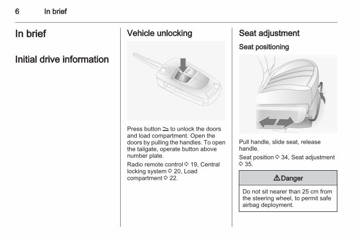
Vehicle unlocking
Press button q to unlock the doorsand load compartment. Open thedoors by pulling the handles. To openthe tailgate, operate button abovenumber plate.Radio remote control 3 19, Centrallocking system 3 20, Loadcompartment 3 22.
Seat adjustmentSeat positioning
Pull handle, slide seat, releasehandle.Seat position 3 34, Seat adjustment3 35.
9 Danger
Do not sit nearer than 25 cm fromthe steering wheel, to permit safeairbag deployment.

In brief 7
Seat backrests
Pull lever, adjust inclination andrelease lever. Allow the backrest toengage audibly. Do not lean on theseat backrest whilst adjusting it.Seat position 3 34, Seat adjustment3 35, Seat folding 3 36.
Seat height
Lever pumping motionup = seat higherdown = seat lower
Seat position 3 34, Seat adjustment3 35.
Power seat adjustment
Operate switches.

8 In brief
Positioning = move front switchforwards/backwards
Height offront part ofseat
= move front part offront switchupwards/downwards
Height ofrear part ofseat
= move rear part offront switchupwards/downwards
Height ofentire seat
= move entire frontswitch upwards/downwards
Backrest = move upper part ofrear switchforwards/backwards
Seat position 3 34, Power seatadjustment 3 37.
Head restraint adjustment
Press release button, adjust heightand engage.Head restraints 3 33.
Seat belt
Pull out the seat belt and engage inbelt buckle. The seat belt must not betwisted and must fit close against thebody. The backrest must not be tiltedback too far (maximum approx. 25 °).To release belt, press red button onbelt buckle.Seat position 3 34, Seat belts3 40, Airbag system 3 43.

In brief 9
Mirror adjustmentInterior mirror
To reduce dazzle, adjust the lever onthe underside of the mirror housing.Interior mirror 3 28, Automatic anti-dazzle interior mirror 3 29.
Exterior mirrors
Select the relevant exterior mirror andadjust it.Convex exterior mirrors 3 27,Electric adjustment 3 27, Foldingexterior mirrors 3 27, Heatedexterior mirrors 3 28.
Steering wheel adjustment
Unlock lever, adjust steering wheel,then engage lever and ensure it isfully locked.Do not adjust steering wheel unlessvehicle is stationary and steeringwheel lock has been released.Airbag system 3 43, Ignitionpositions 3 122.

10 In brief
Instrument panel overview

In brief 11
1 Side air vents ..................... 1192 Fixed air vents .................... 1193 High beam .......................... 106
Headlight flash ................... 106
Turn and lane-changesignals ................................ 108
Exit lighting ......................... 112
Parking lights ..................... 109
Cruise control ....................... 904 Remote control on
steering wheel ...................... 72
Trip computer ..................... 1005 Horn ..................................... 736 Instruments .......................... 797 Windscreen wiper and
washer system, headlightwasher system ..................... 73
Rear window wiper andwasher system ..................... 75
8 Info-Display .......................... 93
Check control, tyrepressure monitoringsystem ................................ 174
Trip computer ..................... 1009 Centre air vents .................. 11910 Hazard warning flashers .... 107
Parking assist ..................... 140
Electronic Stability Control . 137
Descent control system ...... 138
Status LED for anti-theftalarm system ........................ 24
Folding exterior mirrors ........ 27
Eco button for stop/startsystem ................................. 123
11 Infotainment system ............. 1012 Front passenger airbag ........ 4313 Status LEDs for front
passenger airbag ................. 45
Control indicator for frontpassenger seat belt ............. 41
14 Glovebox .............................. 53
15 Fuse box ............................ 16816 Climate control system ....... 11417 Ignition switch with
steering wheel lock ............ 12218 Accelerator pedal ............... 12119 Driver airbag ........................ 4320 Brake pedal ........................ 13421 Clutch pedal ....................... 12122 Steering wheel adjustment . . 7223 Bonnet release ................... 15124 Coin storage ......................... 5425 Card holder .......................... 5426 Light switch ........................ 105
Automatic light control ....... 105
Instrument illumination ....... 110
Rear fog light ...................... 109
Front fog lights ................... 108
Headlight rangeadjustment ......................... 106

12 In brief
Exterior lighting
Turn light switchAUTO = Automatic light control:
Headlights are switchedon and off automatically.
7 = Off (or deactivation ofautomatic light control)
8 = Sidelights9 = Headlights
Press button> = Front fog lightsr = Rear fog light
Lighting 3 105.
Headlight flash, high beam andlow beam
headlightflash
= pull lever
high beam = push leverlow beam = pull lever back
towards steeringwheel
Automatic light control 3 105, Highbeam 3 106, Headlight flash 3 106.
Turn and lane-change signals
right = lever upleft = lever down
Turn and lane-change signals3 108, Parking lights 3 109.

In brief 13
Hazard warning flashers
Operated with the ¨ button.Hazard warning flashers 3 107.
Horn
Press j.
Washer and wiper systemsWindscreen wiper
& = fast% = slow$ = timed interval wiping or
automatic wiping with rainsensor
§ = off
For a single wipe when thewindscreen wiper is off, press thelever down.Windscreen wiper 3 73, Wiperblade replacement 3 157.

14 In brief
Windscreen and headlightwasher systems
Pull lever.Windscreen and headlight washersystem 3 73, Washer fluid 3 153.
Rear window wiper and washersystem
Wiper on = push leverWiper off = pull leverWash = press and hold button
Rear window wiper and washersystem 3 75, Wiper bladereplacement 3 157, Washer fluid3 153.
Climate controlHeated rear window, heatedexterior mirrors
Heating is operated by pressing theRÜ button.Heated rear window 3 31, Heatedexterior mirrors 3 28.

In brief 15
Demisting and defrosting thewindows
Air distribution to V (or l).Cooling A/C (or n) and airrecirculation 4 are switched onautomatically to improve defrostingefficiency (air recirculation 4 isautomatically switched off in vehicleswith electronic climate control).Set temperature to highest level.Set fan speed to highest level.Switch on heated rear window RÜ.
Close centre air vents, open side airvents and direct them towards thedoor windows.Climate control system 3 114.
TransmissionManual transmission
Reverse: with the vehicle stationary,wait 3 seconds after depressingclutch pedal and engage the gear.If the gear does not engage, set thelever to neutral, release the clutchpedal and depress again; then repeatgear selection.Manual transmission 3 131.

16 In brief
Automatic transmission
P = parkR = reverseN = neutralD = drive
Manual mode: move selector leverfrom D to the left.< = higher gear] = lower gear
The selector lever can only be movedout of P when the ignition is on andthe foot brake is applied. To engageP or R, push the release button.Automatic transmission 3 128.
Starting offCheck before starting off■ Tyre pressure and condition 3 174,3 205.
■ Engine oil level and fluid levels3 151.
■ All windows, mirrors, exteriorlighting and number plates are freefrom dirt, snow and ice and areoperational.
■ Proper position of mirrors, seats,and seat belts 3 27, 3 34,3 41.
■ Brake function at low speed,particularly if the brakes are wet.
Starting the engine
■ Turn key to position ACC■ move the steering wheel slightly to
release the steering wheel lock■ manual transmission in neutral■ operate clutch and brake pedals■ automatic transmission in P or N■ do not accelerate■ diesel engines: turn key to ON for
preheating and wait until controlindicator ! extinguishes
■ turn key to START and releaseStarting the engine 3 122.

In brief 17
Stop-start system
If the vehicle is at a low speed or at astandstill and certain conditions arefulfilled, activate an Autostop asfollows:■ Depress the clutch pedal■ shift the selector lever to N■ release the clutch pedalAn Autostop is indicated by theneedle at the AUTOSTOP position inthe tachometer.To restart the engine, depress theclutch pedal again.Stop-start system 3 123.
Parking■ Always apply the electrical parking
brake.Pull switch m.For maximum force, e.g. parkingwith a trailer or on inclines, pullswitch m twice.
■ Switch off the engine and turn theignition key to position LOCK, pushkey into ignition switch and remove.Turn the steering wheel until thesteering wheel lock is felt toengage.For vehicles with automatictransmission, depress foot brakeand shift into P before pushing keyinto ignition switch and removing.
■ If the vehicle is on a level surface oruphill slope, engage first gear ormove the selector lever to P beforeswitching off the ignition. On anuphill slope, turn the front wheelsaway from the kerb.If the vehicle is on a downhill slope,engage reverse gear or move theselector lever to P before switching
off the ignition. Turn the frontwheels towards the kerb.
■ Lock the vehicle with button p onthe radio remote control 3 20.Activate the anti-theft alarm system3 24.
■ Do not park the vehicle on an easilyignitable surface. The hightemperature of the exhaust systemcould ignite the surface.
■ Close windows and sunroof.■ The engine cooling fans may run
after the engine has been switchedoff 3 150.
■ After running at high engine speedsor with high engine loads, operatethe engine briefly at a low load orrun in neutral for approx.1 or 2 minutes, before switching offin order to protect the turbocharger.
Keys, locks 3 18, Laying the vehicleup for a long period of time 3 149.
18 Keys, doors and windows
Keys, doors andwindows
Keys, locks ................................... 18Doors ........................................... 22Vehicle security ............................ 23Exterior mirrors ............................ 27Interior mirrors ............................. 28Windows ...................................... 29Roof ............................................. 31
Keys, locksKeysReplacement keysThe key number is specified in theCar Pass or on a detachable tag.The key number must be quotedwhen ordering replacement keys as itis a component of the immobilisersystem.Locks 3 188.
Lock cylindersDesigned to free-wheel if they areforcefully rotated without the correctkey or if the correct key is not fullyinserted. To reset, turn cylinder withthe correct key until its slot is vertical,remove key and then re-insert it. If thecylinder still free-wheels, turn the keythrough 180° and repeat operation.
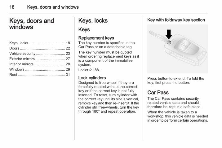
Key with foldaway key section
Press button to extend. To fold thekey, first press the button.
Car PassThe Car Pass contains securityrelated vehicle data and shouldtherefore be kept in a safe place.When the vehicle is taken to aworkshop, this vehicle data is neededin order to perform certain operations.

Keys, doors and windows 19
Radio remote control
Used to operate:■ Central locking system■ Anti-theft locking system■ Anti-theft alarm systemThe radio remote control has a rangeof approx. 6 metres. This range canbe affected by external influences.The hazard warning flashers confirmoperation.Handle with care, protect frommoisture and high temperatures andavoid unnecessary operation.
FaultIf the central locking system cannotbe operated with the radio remotecontrol, it may be due to the following:■ Range exceeded.■ Battery voltage too low.■ Frequent, repeated operation of the
radio remote control while not inrange, which will requirereprogramming. Seek theassistance of a workshop.
■ Overload of the central lockingsystem by operating at frequentintervals, the power supply isinterrupted for a short time.
■ Interference from higher-powerradio waves from other sources.
Unlocking 3 20.
Radio remote control batteryreplacementReplace the battery as soon as therange reduces.
Batteries do not belong in householdwaste. They must be disposed of atan appropriate recycling collectionpoint.
Key with foldaway key section
Extend the key and open the unit.Replace the battery (battery typeCR2032), paying attention to theinstallation position. Close the unit.

20 Keys, doors and windows
Key with fixed key sectionOpen the unit with a small screwdriverin the notch on the cover. Replace thebattery (battery type CR2032), payingattention to the installation position.Close the unit.
Central locking systemUnlocks and locks doors, loadcompartment and fuel filler flap.A pull on an interior door handleunlocks the respective door. Pullingthe handle once more opens the door.NoteIn the event of an accident in whichairbags or belt pretensioners aredeployed, the vehicle isautomatically unlocked.
Unlocking
Press button q.NoteIf no door is opened within5 minutes after the vehicle has beenunlocked, the vehicle is relockedautomatically (and the anti-theftalarm is reactivated).
When button q is pressed, theinstrument panel illuminates forapprox. 30 seconds or until ignitionswitch is turned to position ACC.
LockingClose doors, load compartment, fuelfiller flap, bonnet, windows andsunroof.
Press button p.The central locking system can beactivated with the windows open.
Keys, doors and windows 21
NoteFor safety reasons, the vehiclecannot be locked or unlocked via theremote control (and the anti-theftsystems will not be activated) if thekey is in the ignition switch.
If the driver's door is not closedproperly, the central locking systemwill not work.
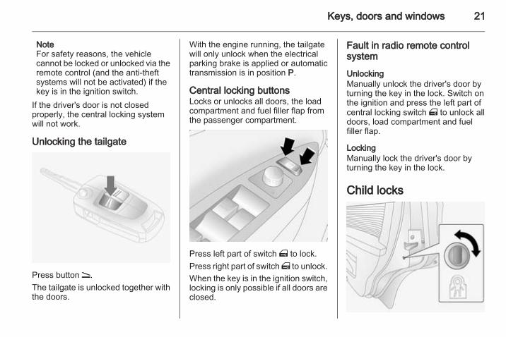
Unlocking the tailgate
Press button q.The tailgate is unlocked together withthe doors.
With the engine running, the tailgatewill only unlock when the electricalparking brake is applied or automatictransmission is in position P.
Central locking buttonsLocks or unlocks all doors, the loadcompartment and fuel filler flap fromthe passenger compartment.
Press left part of switch m to lock.Press right part of switch m to unlock.When the key is in the ignition switch,locking is only possible if all doors areclosed.
Fault in radio remote controlsystem
UnlockingManually unlock the driver's door byturning the key in the lock. Switch onthe ignition and press the left part ofcentral locking switch m to unlock alldoors, load compartment and fuelfiller flap.
LockingManually lock the driver's door byturning the key in the lock.
Child locks

22 Keys, doors and windows
9 Warning
Use the child locks wheneverchildren are occupying the rearseats.
Using a key or suitable screwdriver,turn button on rear door lock to thehorizontal position. The door cannotbe opened from inside.For deactivation, turn the child lock tothe vertical position.
DoorsLoad compartmentTailgate
Opening
Operate the button above the numberplate and lift the tailgate.If the tailgate is open when the ignitionis switched on, control indicator 1illuminates in the instrument cluster3 90.Central locking system 3 20.
Closing
Use the interior handle.Do not operate the button above thenumber plate while closing thetailgate, as this will unlock it again.Central locking system 3 20.

Keys, doors and windows 23
Fault
To open the tailgate in the event ofpower interruption:Remove the interior trim cover fromthe central latch area, then push thelever using a suitable tool.
General hints for operatingtailgate
9 Warning
Do not drive with the tailgate openor ajar, e.g. when transportingbulky objects, since toxic exhaust
gases, which cannot be seen orsmelled, could enter the vehicle.This can cause unconsciousnessand even death.
Caution
Before opening the tailgate checkoverhead obstructions, such as agarage door, to avoid damage tothe tailgate. Always check themoving area above and behind thetailgate.
NoteThe installation of certain heavyaccessories onto the tailgate mayaffect its ability to remain open.
Vehicle securityAnti-theft locking system
9 Warning
Do not use the system if there arepeople in the vehicle! The doorscannot be unlocked from theinside.
The system deadlocks all the doors.All doors must be closed otherwisethe system cannot be activated.If the ignition was on, the driver's doormust be opened and closed once sothat the vehicle can be secured.Unlocking the vehicle disables themechanical anti-theft locking system.This is not possible with the centrallocking button.

24 Keys, doors and windows
Activating
Press button p on the radio remotecontrol twice within 3 seconds.Alternatively, turn key in driver's doortowards rear of vehicle again within3 seconds after locking.
Anti-theft alarm systemThe system monitors:■ Doors, tailgate, bonnet■ Passenger compartment including
adjoining load compartment■ Vehicle inclination, e.g. if it is raised
■ Siren power supply■ Ignition
Activation
Ensure the doors, tailgate, fuel fillerflap, bonnet, windows and sunroofare closed.Press button p on radio remotecontrol or manually lock the driver'sdoor.
The system is activated:■ Automatically, 30 seconds after
locking the vehicle (initialisation ofthe system)
■ Directly by pressing p on the radioremote control once more afterlocking
If the hazard warning lights do notflash once upon activation or thecontrol indicator flashes rapidly, thismay indicate that a door, the tailgateor the bonnet is not fully closed.NoteChanges to the vehicle interior suchas the use of seat covers, and openwindows or sunroof, could impair thefunction of passenger compartmentmonitoring.

Keys, doors and windows 25
Activation without monitoring ofpassenger compartment andvehicle inclination
Switch off the monitoring ofpassenger compartment and vehicleinclination when people or animalsare being left in the vehicle, becauseof high volume ultrasonic signals,movements triggering the alarm andwhen the vehicle is on a ferry or train.1. Close tailgate, bonnet, windows
and sunroof.2. Press button o. Control
indicator o illuminates yellow inthe instrument cluster.
3. Close doors.4. Activate the anti-theft alarm
system.Press button o again to cancel.Control indicator o extinguishes.
Status LED
Status LED is located in the centreconsole.
Status during the first 30 seconds ofanti-theft alarm system activation:LEDilluminates
= test, arming delay.
LED flashesquickly
= doors, tailgate orbonnet notcompletely closed,or system fault.
Status after system is armed:LED flashesslowly
= system isarmed.
LED flashesquickly 3 timesafter unlocking
= system isdisarmed.
Seek the assistance of a workshop inthe event of faults.
DeactivationUnlocking the vehicle deactivatesanti-theft alarm system. Hazardwarning lights flash twice upondeactivation.If no door is opened or the engine isnot started within 30 seconds after thevehicle has been unlocked, thevehicle is relocked automatically andthe alarm is reactivated.
26 Keys, doors and windows
If the alarm has been triggered, thehazard warning lights will not flashupon deactivation.
AlarmWhen triggered, the alarm sounds viaa separate battery-backed powersounder, and the hazard warninglights flash simultaneously. Thenumber and duration of alarm signalsare stipulated by legislation.The alarm can be silenced bypressing any button of the radioremote control or manually unlockingthe driver's door with the ignition key.The anti-theft alarm system isdeactivated at the same time.
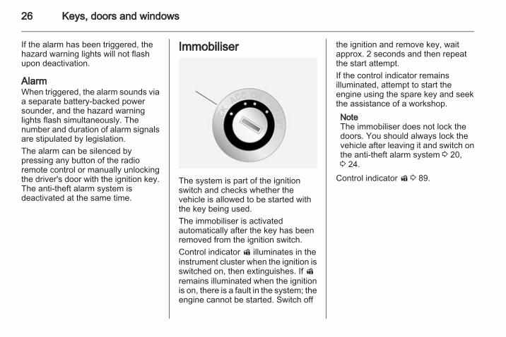
Immobiliser
The system is part of the ignitionswitch and checks whether thevehicle is allowed to be started withthe key being used.The immobiliser is activatedautomatically after the key has beenremoved from the ignition switch.Control indicator d illuminates in theinstrument cluster when the ignition isswitched on, then extinguishes. If dremains illuminated when the ignitionis on, there is a fault in the system; theengine cannot be started. Switch off
the ignition and remove key, waitapprox. 2 seconds and then repeatthe start attempt.If the control indicator remainsilluminated, attempt to start theengine using the spare key and seekthe assistance of a workshop.NoteThe immobiliser does not lock thedoors. You should always lock thevehicle after leaving it and switch onthe anti-theft alarm system 3 20,3 24.
Control indicator d 3 89.

Keys, doors and windows 27
Exterior mirrorsConvex shapeThe convex exterior mirror containsan aspherical area and reduces blindspots. The shape of the mirror makesobjects appear smaller, which willaffect the ability to estimatedistances.
Electric adjustment
Select the relevant exterior mirror byturning the switch to left (L) or right(R). Then swivel the control to adjustthe mirror.
Folding
For pedestrian safety, the exteriormirrors will swing out of their normalmounting position if they are struckwith sufficient force. Reposition themirror by applying slight pressure tothe mirror housing.
Manual foldingPress lightly on the outside of themirror housing to fold in the exteriormirrors.
Electric folding
With ignition switch in positions ACCor ON, press button n and bothexterior mirrors will fold in.Press button n again - both exteriormirrors return to their original position.If an electrically folded mirror ismanually extended, pressing buttonn will only electrically extend theother mirror. Pressing button n againfolds both mirrors back in.Fold mirrors back to the drivingposition before driving the vehicle.

28 Keys, doors and windows
Heated mirrors
Operated by pressing the RÜ button.LED illuminates in the button.Heating works with the key in ignitionswitch positions ACC or ON and isswitched off automatically after ashort time.To avoid discharging the battery,operate only with the engine running.Do not operate when you are juststarting the vehicle, or if there is abuild up of snow or ice on the exteriormirrors.
Do not use sharp instruments orabrasive cleaners on the exteriormirrors and avoid scratching ordamaging the heating elements.
Automatic dimming
Exterior mirror on the driver's sidedims to reduce glare automatically inconjunction with the automatic anti-dazzle interior mirror 3 29.
Interior mirrorsManual anti-dazzle
To reduce dazzle, adjust the lever onthe underside of the mirror housing.

Keys, doors and windows 29
Automatic anti-dazzle
Press button on mirror housing to turnfunction on; button illuminates anddazzle from following vehicles at nightis automatically reduced. Pressbutton again to turn function off.There are two light sensors in themirror housing. To avoid interferenceand loss of function, do not cover thesensors or hang anything on themirror.
WindowsWindscreenHeat-reflecting windscreenThe heat-reflecting windscreen has acoating which reflects solar radiation.Also data signals, e.g. from tollstations, might be reflected.
The marked areas of the windscreenbehind the interior mirror are notcovered with the coating. Devices forelectronic data recording and fee
payment must be attached in theseareas. Otherwise data recordingmalfunctions may occur.
Windscreen stickersDo not attach stickers such as tollroad stickers or similar on thewindscreen in the area of the interiormirror. Otherwise the detection zoneof the sensor could be restricted.
Power windows
9 Warning
Take care when operating thepower windows. Risk of injury,particularly to children.If there are children on the rearseats, switch on the child safetysystem for the power windows.Keep a close watch on thewindows when closing them.Ensure that nothing becomestrapped in them as they move.

30 Keys, doors and windows
Power windows can be operated:■ with ignition on,■ within 10 minutes of switching
ignition off.After switching off the ignition,window operation is disabled whenthe driver's door is opened.
Operate the switch for the respectivewindow by pushing to open or pullingto close.For incremental operation: Push orpull switch briefly.For automatic opening or closing:Push or pull switch for longer.Window moves up or down
automatically with safety functionenabled. To stop movement, operatethe switch once more in the samedirection.Additional switches are located in thefront passenger's door and the reardoors. The rear windows do not openfully.
Safety functionIf the window glass encountersresistance above the middle of thewindow during automatic closing, it isimmediately stopped and openedagain.
Override safety functionIn the event of closing difficulties dueto frost or the like, pull the relevantwindow switch several times until thewindow is closed. The window movesup with the safety function disabled.
Child safety system for rearwindows
Press switch z to deactivate reardoor power windows. To reactivate,press z again.With the child safety system on, reardoor windows can only be operatedvia the switches in the driver's door.
OverloadIf the windows are repeatedlyoperated within short intervals, thewindow operation is disabled forsome time.

Keys, doors and windows 31
Heated rear window
Operated by pressing the RÜ button.LED illuminates in the button.Heating works with the key in ignitionswitch positions ACC or ON and isswitched off automatically after ashort time.To avoid discharging the battery,operate only with the engine running.Do not operate when you are juststarting the vehicle, or if there is abuild up of snow or ice on the rearwindow.
Do not use sharp instruments orabrasive cleaners on the rear windowand avoid scratching or damaging theheating elements.
Sun visors
The sun visors can be folded down orswivelled to the side to preventdazzling.Sun visors have vanity mirrors and aticket holder on the rear. When thevanity mirror covers are opened, thesun visor light illuminates.The mirror covers should be closedwhen driving.
RoofSunroof
9 Warning
Take care when operating thesunroof. Risk of injury, particularlyto children.Keep a close watch on themovable parts when operatingthem. Ensure that nothingbecomes trapped in them as theymove.
Slide/tilt sunroof

32 Keys, doors and windows
For incremental operation, brieflypress the switch in the requireddirection. For automatic opening orclosing, press and hold the switch.
OpenPress switch rearwards; it will openautomatically unless the switch ispressed again in another direction, orreleased.NoteIf the top of the roof is wet, tiltsunroof, allow water to run off andthen open sunroof.
ClosePress and hold switch forwards.Release switch when sunroofreaches desired position.
TiltPress and hold switch upwards.Release switch when sunroofreaches desired position.To return sunroof to its originalposition, pull and hold switchdownwards. Release switch whensunroof reaches desired position.
General hints
Function standbyThe sunroof can be operated:■ with ignition on,■ within 10 minutes of switching
ignition off,After switching off the ignition,sunroof operation is disabled whendriver's door is opened.

Seats, restraints 33
Seats, restraints
Head restraints ............................ 33Front seats ................................... 34Rear seats ................................... 38Seat belts ..................................... 40Airbag system .............................. 43Child restraints ............................. 47
Head restraints
Position
9 Warning
Only drive with the head restraintset to the proper position.
The upper edge of the head restraintshould be at upper head level. If thisis not possible for extremely tallpeople, set to highest position, andset to lowest position for small people.
Height adjustment
Press release button, adjust heightand engage.Pull head restraint up to raise. Pushhead restraint down while pressingthe release button to lower the headrestraint.
RemovalInsert a suitable tool into the smallhole in the side of the guide sleevewithout the release button anddepress the lock. Press the releasebutton on the other guide sleeve andpull up the head restraint.

34 Seats, restraints
Stow head restraints securely in loadcompartment.
Active head restraintsIn the event of a rear-end impact, theactive head restraints automaticallytilt forwards. Thus the head issupported so that the risk of whiplashinjury is reduced.NoteDo not attach objects or componentsthat are not approved for yourvehicle to the head restraints. Theseaffect the protective effect of thehead restraints and can be propelledthrough the vehicle in anuncontrolled manner if the driverbrakes hard or an accident occurs.
Front seatsSeat position
9 Warning
Only drive with the seat correctlyadjusted.
■ Sit with buttocks as far back againstthe backrest as possible. Adjust thedistance between the seat and thepedals so that legs are slightlyangled when pressing the pedals.Slide the front passenger seat asfar back as possible.
■ Sit with shoulders as far backagainst the backrest as possible.Set the backrest rake so that it ispossible to easily reach thesteering wheel with arms slightlybent. Maintain contact betweenshoulders and the backrest whenturning the steering wheel. Do notangle the backrest too far back. Werecommend a maximum rake ofapproximately 25°.
■ Adjust the steering wheel 3 72.■ Set seat height high enough to
have a clear field of vision on allsides and of all display instruments.There should be at least one handof clearance between head and theroof frame. Your thighs should restlightly on the seat without pressinginto it.
■ Adjust the head restraint 3 33.■ Adjust the height of the seat belt3 41.
■ Adjust the lumbar support so that itsupports the natural shape of thespine.

Seats, restraints 35
Seat adjustment
9 Danger
Do not sit nearer than 25 cm fromthe steering wheel, to permit safeairbag deployment.
9 Warning
Never adjust seats while driving asthey could move uncontrollably.
9 Warning
Never store any objects under theseats.
Drive only with engaged seats andbackrests.
Seat positioning
Pull handle, slide seat, releasehandle.
Seat backrests
Pull lever, adjust inclination andrelease lever. Allow the backrest toengage audibly.Do not lean on the seat backrestwhilst adjusting it.

36 Seats, restraints
Seat height
Lever pumping motionup = seat higherdown = seat lower
Lumbar support
Adjust lumbar support to suit personalrequirements using the lever.To increase or decrease lumbarsupport, move lever forwards orbackwards.
Seat folding
Caution
When seat height is in highestposition, push head restraintsdown and lift up sun visors beforefolding backrest forwards.
Push head restraint all the way down.Slide seat as far back as it will go.Lift release lever and fold backrestdown onto seat cushion. Lower leverand backrest engages in loweredposition.

Seats, restraints 37
Slide seat forwards.To return the backrest to its originalposition, slide seat as far back as itwill go, lift release lever, move thebackrest to upright position, lowerlever and the backrest engages.Folding the backrest forwards ispossible only when the backrest is inan upright position.Do not operate lever to adjust lumbarsupport with backrest tilted forward.
Power seat adjustment
9 Warning
Care must be taken whenoperating the power seats. Thereis a risk of injury, particularly forchildren. Articles could becometrapped.Keep a close watch on the seatswhen adjusting them. Vehiclepassengers should be informedaccordingly.
Seat lengthwise positionMove front switch forwards/backwards.
Seat heightMove front of switch upwards/downwards to adjust height of frontpart of seat cushion.Move rear of switch upwards/downwards to adjust height of rearpart of seat cushion.Move front and rear of switchupwards/downwards to adjust heightof entire seat cushion.
Seat backrests
Move upper part of rear switchforwards/backwards.The seat backrest must not be tiltedback too far (recommendedmaximum tilting angle approx. 25°).

38 Seats, restraints
Heating
Adjust heating to the desired settingby pressing the ß button for therespective seat one or more timeswith the ignition switch set to ACC orON. The control indicator in the buttonindicates the setting.To deactivate heating, set the heatinglevel to its lowest setting and pressthe ß button. The control indicator inthe button will extinguish.Prolonged use of the highest settingfor people with sensitive skin is notrecommended.
If temperature continues to rise, turnseat heating off and seek theassistance of a workshop.
Rear seats
Seat backrests
To adjust seat backrests, lift releaselever on top of backrest and movebackrest forwards/backwards todesired position.Do not lean on the backrest whilstadjusting it.When folding the backrests, ensurethe seat belts are unbuckled.

Seats, restraints 39
9 Warning
Never adjust seats while driving asthey could move uncontrollably.
Seat folding
The load compartment can beenlarged by folding the seatbackrests onto the seat cushions.To fold backrests separately,unbuckle all three rear seat belts andensure front seats are not in areclined position.
Push head restraints all the waydown, lift backrest release lever andfold backrest forwards and down ontoseat cushion.Do not allow passengers to sit on afolded backrest, or place anyunrestrained loads on it.To move backrest to its originalposition, lift and push the backrestinto place and ensure the backrestengages.Safety net 3 69.
Armrest
Fold armrest down. The armrestcontains cupholders and a storagebox.

40 Seats, restraints
Seat belts
The seat belts are locked duringheavy acceleration or deceleration ofthe vehicle holding the occupants inthe seated position. Thereby the riskof injury is considerably reduced.
9 Warning
Fasten seat belt before each trip.In the event of an accident, peoplenot wearing seat belts endangertheir fellow occupants andthemselves.
Seat belts are designed to be used byonly one person at a time.Child restraint system 3 47.Periodically check all parts of the beltsystem for damage and properfunctionality.Have damaged componentsreplaced. After an accident, have thebelts and triggered belt pretensionersreplaced by a workshop.NoteMake sure that the belts are notdamaged by shoes or sharp-edgedobjects or trapped. Prevent dirt fromgetting into the belt retractors.
Seat belt reminderFront seats are equipped with a seatbelt reminder, indicated for driver seatby control indicator X in theinstrument cluster 3 83 and forpassenger seat by control indicatork on the passenger side of theinstrument panel 3 41.
Belt force limitersLocated on the front seats. Stress onthe body is reduced by the gradualrelease of the belt during a collision.
Belt pretensionersIn the event of a head-on collision orside impact of a certain severity, thefront seat belts are tightened.
9 Warning
Incorrect handling (e.g. removal orfitting of belts) can trigger the beltpretensioners.
Deployment of the belt pretensionersis indicated by illumination of controlindicator v 3 83.Triggered belt pretensioners must bereplaced by a workshop. Beltpretensioners can only be triggeredonce.NoteDo not affix or install accessories orother objects that may interfere withthe operation of the belt

Seats, restraints 41
pretensioners. Do not make anymodifications to belt pretensionercomponents as this will invalidatethe vehicle type approval.
Three-point seat beltFastening
Withdraw the belt from the retractor,guide it untwisted across the bodyand insert the latch plate into thebuckle. Tighten the lap belt regularlywhilst driving by pulling the shoulderbelt.Seat belt reminder X 3 83.
Loose or bulky clothing prevents thebelt from fitting snugly. Do not placeobjects such as handbags or mobilephones between the belt and yourbody.
9 Warning
The belt must not rest against hardor fragile objects in the pockets ofyour clothing.
Height adjustment
1. Squeeze release buttonstogether.
2. Slide adjuster up or down.3. Ensure adjuster latches into
position.

42 Seats, restraints
Adjust the height so that the belt liesacross the shoulder. It must not lieacross the throat or upper arm.Do not adjust while driving.
Removing
To release belt, press red button onbelt buckle.
Using the seat belt whilepregnant
9 Warning
The lap belt must be positioned aslow as possible across the pelvisto prevent pressure on theabdomen.

Seats, restraints 43
Front passenger seat beltreminder
When the engine is running, controlindicator k flashes then illuminates ifthe passenger seat is occupied andthe seat belt is not engaged.If vehicle speed exceeds 14 mph, kwill flash for 100 seconds along witha warning chime, then illuminate untilthe seat belt is fastened.Illuminates briefly when ignition isswitched on.Control indicator X for driver's seatbelt reminder 3 83.
Airbag systemThe airbag system consists of anumber of individual systemsdepending on the scope ofequipment.When triggered the airbags inflatewithin milliseconds. They also deflateso quickly that it is often unnoticeableduring the collision.
9 Warning
If handled improperly the airbagsystems can be triggered in anexplosive manner.
NoteThe airbag systems and beltpretensioner control electronics arelocated in the centre console area.Do not put any magnetic objects inthis area.Do not stick anything on the airbagcovers and do not cover them withother materials.
Each airbag is triggered only once.Have deployed airbags replaced bya workshop. Furthermore, it might benecessary to have the steeringwheel, the instrument panel, parts ofthe panelling, the door seals,handles and the seats replaced.Do not make any modifications tothe airbag system as this willinvalidate the vehicle type approval.
When the airbags inflate, escapinghot gases may cause burns.Control indicator v for airbag systems3 83.
Front airbag systemThe front airbag system consists ofone airbag in the steering wheel andone in the instrument panel on thefront passenger side. These can beidentified by the word AIRBAG.

44 Seats, restraints
The warning label reminds that theuse of rear-facing child restraintsystems on the front passenger seatis not permitted. Risk of fatal injury.The front airbag system is triggered inthe event of a front-end impact of acertain severity. The ignition must beswitched on.
The inflated airbags cushion theimpact, thereby considerablyreducing the risk of injury to the upperbody and head of the front seatoccupants.
9 Warning
Optimum protection is onlyprovided when the seat is in theproper position 3 34.Keep the area in which the airbaginflates clear of obstructions.
Fit the seat belt correctly andengage securely. Only then theairbag is able to protect.
Side airbag system
The side airbag system consists of anairbag in each front seat backrest.This can be identified by the wordAIRBAG.The side airbag system is triggered inthe event of a side impact of a certainseverity. The ignition must beswitched on.

Seats, restraints 45
The inflated airbags cushion theimpact, thereby considerablyreducing the risk of injury to the upperbody and pelvis in the event of a side-on collision.
9 Warning
Keep the area in which the airbaginflates clear of obstructions.
NoteOnly use protective seat covers thathave been approved for the vehicle.Be careful not to cover the airbags.
Curtain airbag systemThe curtain airbag system consists ofan airbag in the roof frame on eachside. This can be identified by theword AIRBAG on the roof pillars.The curtain airbag system is triggeredin the event of a side-on impact of acertain severity. The ignition must beswitched on.
The inflated airbags cushion theimpact, thereby considerablyreducing the risk of injury to the headin the event of a side-on impact.
9 Warning
Keep the area in which the airbaginflates clear of obstructions.The hooks on the handles in theroof frame are only suitable forhanging up light articles ofclothing, without coat hangers. Donot keep any items in theseclothes.
Airbag deactivationThe front passenger airbag systemmust be deactivated if a child restraintsystem is to be fitted on this seat. Thebelt pretensioners and all driverairbag systems will remain active.

46 Seats, restraints
The front passenger airbag systemcan be deactivated via a key-operated switch on the right side ofthe instrument panel.
Use the ignition key to choose theposition:*OFF
= front passenger airbagsystems are deactivatedand will not inflate in theevent of a collision. Controlindicator * illuminatescontinuously on thepassenger side of theinstrument panel. A childrestraint system can beinstalled in accordance withthe chart Child restraintinstallation locations3 49. No adult person isallowed to occupy the frontpassenger seat.
VON
= front passenger airbagsystems are active. A childrestraint system must notbe installed.
9 Danger
Risk of fatal injury for a child usinga child restraint system on a seatwith activated front passengerairbag.
Risk of fatal injury for an adultperson on a seat with deactivatedfront passenger airbag.
Control indicators for the frontpassenger airbag system are locatedon the passenger side of theinstrument panel.As long as control indicator is notilluminated, the front passengerairbag system will inflate in the eventof a collision.Change status only when the vehicleis stopped with the ignition off.Status remains until the next change.

Seats, restraints 47
Control indicator V for frontpassenger airbag 3 80.
Child restraintsChild restraint systemsWe recommend the Vauxhall childrestraint system which is tailoredspecifically to the vehicle.When a child restraint system is beingused, pay attention to the followingusage and installation instructionsand also those supplied with the childrestraint system.Always comply with local or nationalregulations. In some countries, theuse of child restraint systems isforbidden on certain seats.
9 Warning
When using a child restraintsystem on the front passengerseat, the airbag systems for thefront passenger seat must bedeactivated; if not, the triggering ofthe airbags poses a risk of fatalinjury to the child.
This is especially the case if rear-facing child restraint systems areused on the front passenger seat.
Airbag deactivation 3 45.
Selecting the right systemThe rear seats are the mostconvenient location to fasten a childrestraint system.Children should travel facingrearwards in the vehicle as long aspossible. This makes sure that thechild's backbone, which is still veryweak, is under less strain in the eventof an accident.Suitable are restraint systems thatcomply with ECE 44-03 orECE 44-04. Check local laws andregulations for mandatory use of childrestraint systems.Ensure that the child restraint systemto be installed is compatible with thevehicle type.Ensure that the mounting location ofthe child restraint system within thevehicle is correct.

48 Seats, restraints
Allow children to enter and exit thevehicle only on the side facing awayfrom the traffic.When the child restraint system is notin use, secure the seat with a seat beltor remove it from the vehicle.NoteDo not stick anything on the childrestraint systems and do not coverthem with any other materials.A child restraint system which hasbeen subjected to stress in anaccident must be replaced.

Seats, restraints 49
Child restraint installation locationsPermissible options for fitting a child restraint system
Weight and age classOn front passenger seat
On rear outboard seats On rear centre seatactivated airbag deactivated airbag
Group 0: up to 10 kgor approx. 10 months
X U1 U, < X
Group 0+: up to 13 kgor approx. 2 years
X U1 U, < X
Group I: 9 to 18 kgor approx. 8 months to 4 years
X U1 U, < X
Group II: 15 to 25 kgor approx. 3 to 7 years
X X U X
Group III: 22 to 36 kgor approx. 6 to 12 years
X X U X
1 = Only if front passenger seat airbag system is deactivated 3 45. Child restraint system must be secured using a three-point seat belt. Move seat height adjustment to uppermost position and ensure that vehicle seat belt runs forwardsfrom the upper anchorage point.
< = Vehicle seat with ISOFIX mounting available. When mounting with ISOFIX, only ISOFIX child restraint systems thathave been approved for the vehicle may be used.
U = Universal suitability in conjunction with three-point seat belt.X = No child restraint system permitted in this weight and age class.

50 Seats, restraints
Permissible options for fitting an ISOFIX child restraint system
Weight and age class Size class FixtureOn frontpassenger seat
On rearoutboard seats
On rearcentre seat
Group 0: up to 10 kg or approx. 10 months E ISO/R1 X IL X
Group 0+: up to 13 kg or approx. 2 years E ISO/R1 X IL X
D ISO/R2 X IL X
C ISO/R3 X IL X
Group I: 9 to 18 kg or approx. 8 months to 4 years D ISO/R2 X IL X
C ISO/R3 X IL X
B ISO/F2 X IUF X
B1 ISO/F2X X IUF X
A ISO/F3 X IUF X
IL = Suitable for particular ISOFIX restraint systems of the 'vehicle-specific', 'restricted' or 'semi-universal' categories.The ISOFIX restraint system must be approved for the specific vehicle type.
IUF = Suitable for ISOFIX forward-facing child restraint systems of universal category approved for use in this weight andage class.
X = No ISOFIX child restraint system approved in this weight and age class.

Seats, restraints 51
ISOFIX size class and seat deviceA - ISO/F3 = Forward-facing child restraint system for children of maximum size in the weight class 9 to 18 kg.B - ISO/F2 = Forward-facing child restraint system for smaller children in the weight class 9 to 18 kg.B1 - ISO/F2X = Forward-facing child restraint system for smaller children in the weight class 9 to 18 kg.C - ISO/R3 = Rear-facing child restraint system for children of maximum size in the weight class up to 18 kg.D - ISO/R2 = Rear-facing child restraint system for smaller children in the weight class up to 18 kg.E - ISO/R1 = Rear-facing child restraint system for young children in the weight class up to 13 kg.

52 Seats, restraints
ISOFIX child restraintsystems
Fasten vehicle-approved ISOFIXchild restraint systems to the ISOFIXmounting brackets.Permitted installation positions forspecific vehicle ISOFIX child restraintsystems are marked in the table by IL.No more than two ISOFIX childrestraint systems can be installed onthe rear seats at the same time,though not on the rear centre seat.ISOFIX mounting brackets areindicated by a label on the backrest.
Top-tether fastening eyes
The Top-tether anchors located onthe rear of the backrests are designedto hold child restraints which comeequipped with Top-tether anchorattachments only. Follow theinstructions provided with theTop-tether child restraint system.For use of ISOFIX and Top-tetherfixings, universal ISOFIX childrestraint systems may be used.Permitted installation positions aremarked in the table by IUF.

Storage 53
Storage
Storage compartments ................ 53Load compartment ....................... 65Roof rack system ......................... 70Loading information ..................... 70
Storage compartments
9 Warning
Do not store heavy or sharpobjects in the storagecompartments. Otherwise vehicleoccupants could be injured byobjects being thrown around in theevent of hard braking, a suddenchange in direction or an accident.
Glovebox
The glovebox will illuminate whenopened.The glovebox partition can beremoved from its groove. Store thepartition in the groove on the far left-hand side of the glovebox.The glovebox should be closed whilstdriving.
Lockable gloveboxLock and unlock the glovebox with thekey.
CupholdersCupholders are located in the front ofthe centre console.The cupholder is flexible, allowingdifferent size drink containers to bestored.Additional cupholders are located inthe centre rear seat armrest. Folddown the armrest to access thecupholder.

54 Storage
Front storageConsole net
Located in the front passenger footwell.
Coin storage
Pull handle to open. Push door firmlyto close.
Card holderLocated above the coin storagecompartment. A card can be retainedin the slot for convenient use.
Sunglasses storage
To open: push the rear part of thecover.To close: pull up cover and push ituntil it latches into place.Do not use for storing heavy objects.

Storage 55
Underseat storageFront passenger seat undertray
Pull up on front of tray then pull itforwards. Push the tray towards theseat to return it to its original position.
Armrest storageConsole box in front armrest
To open: pull up lever and lift the lid.To close: lower lid and push it downuntil it latches into position.
Centre console storageTo access the storage compartment,cigarette lighter and AUX input, slidethe cupholder tray rearwards.Cigarette lighter 3 78.
AUX input - see Infotainment systeminstruction manual for furtherinformation.
Rear carrier system
The rear carrier system (Flex-Fixsystem) allows bicycles to beattached to a pull-out carrierintegrated into the vehicle floor. Thetransportation of other objects is notpermitted.The maximum load of the rear carriersystem is 40 kg. The maximum loadper bicycle is 20 kg.

56 Storage
If not in use, the carrier system mustbe slid back into the vehicle floor.A multifunction box is offered as anaccessory for the rear carrier system.There must not be any objects on thebicycles that could become looseduring transportation.
Caution
Do not attach bicycles with carbonpedal cranks to bicycle carriers.The bicycles might get damaged.
ExtendingOpen the tailgate.
9 Warning
No-one should be in the extensionzone of the rear carrier system,risk of injury.
Raise release lever. The systemdisengages and travels quickly out ofthe bumper.
Completely pull out the rear carriersystem until you hear it engage.Ensure that it is not possible to pushin the rear carrier system withoutpulling the release lever again.
9 Warning
It is only permissible to fit objectsto the rear carrier system if thesystem has been correctlyengaged. If the rear carrier systemwill not engage correctly, do not fitobjects to the system and slide thesystem back. Seek the assistanceof a workshop.
Storage 57
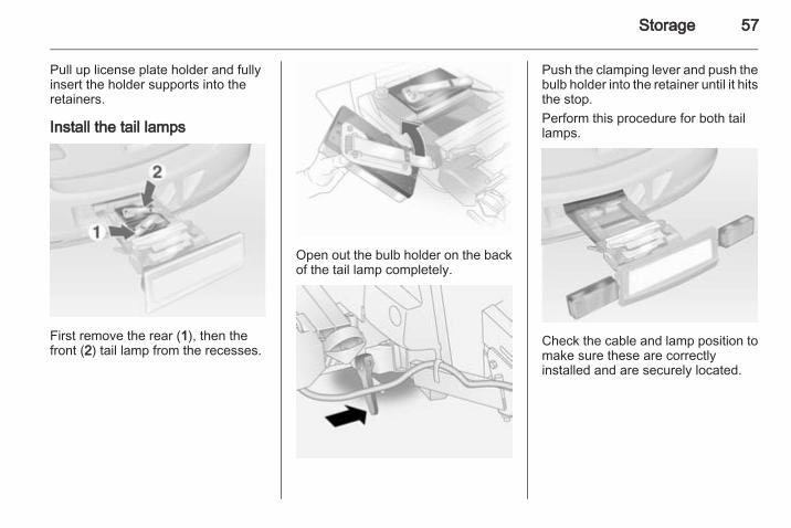
Pull up license plate holder and fullyinsert the holder supports into theretainers.
Install the tail lamps
First remove the rear (1), then thefront (2) tail lamp from the recesses.
Open out the bulb holder on the backof the tail lamp completely.
Push the clamping lever and push thebulb holder into the retainer until it hitsthe stop.Perform this procedure for both taillamps.
Check the cable and lamp position tomake sure these are correctlyinstalled and are securely located.

58 Storage
Lock the rear carrier system
Swivel the left clamping lever (1) backfirst, followed by the right clampinglever (2) until they stop. Bothclamping levers must pointbackwards, otherwise safefunctionality is not guaranteed.NoteClose the tailgate!
Unfold pedal crank recesses
Fold one or both pedal crankrecesses upwards until the diagonalsupport engages.
Remove the pedal crank mounts fromthe pedal crank recesses.

Storage 59
Adapting the rear carrier systemto a bicycle
With the rotary lever on the pedalcrank recess, roughly adapt theadjustable pedal crank unit to theprotrusion of the pedal crank.If the bicycle has straight pedalcranks, unscrew the pedal crank unitcompletely (position 5).
If the bicycle has curved pedalcranks, screw in the pedal crank unitall the way (position 1).
Press the release lever and withdrawthe wheel recesses.
Push the release lever on the strapretainer and remove the strapretainer.

60 Storage
Prepare the bicycle forattachment
NoteThe maximum width for the pedalcrank is 38.3 mm and the maximumdepth is 14.4 mm.
Rotate the left pedal (without a chaincog) vertically downwards. The pedalon the left pedal crank must behorizontal.The front bicycle must have its frontwheel facing left.The rear bicycle must have its frontwheel facing right.
Attaching a bicycle to the rearcarrier system
Put on the bicycle. The pedal crankhere must be placed in the pedalcrank recess opening as shown in theillustration.
Caution
Make sure that the pedal does nottouch the surface of the rear endcarrier. Otherwise the bicyclechainset might be damaged duringtransport.
Insert pedal crank mount into outerrail of each pedal crank recess fromabove and slide downwards as far asit will go.

Storage 61
Attach the pedal crank by rotating theattachment screw on the pedal crankmount.
Place the wheel recesses such thatthe bicycle is more or less horizontal.Here, the distance between thepedals and the tailgate should be atleast 5 cm.Both bicycle tyres must be in thewheel recesses.
Caution
Make sure to pull out the wheelrecesses as far as necessary tohave both bicycle tyres placed inthe recesses. Otherwise ahorizontal mounting of the bicycleis not ensured. Disregard couldlead to damage of the bicyclewheels caused by hot exhaustfumes.
Align the bicycle in the longitudinaldirection of the vehicle: Slightlyloosen the pedal mount.
Place the bicycle upright using therotary lever on the pedal crankrecess.If the two bicycles obstruct oneanother, the relative positions of thebicycles can be adapted by adjustingthe wheel recesses and the rotarylever on the pedal crank recess untilthe bicycles no longer touch oneanother. Make sure there is sufficientclearance from the vehicle.
Tighten the attachment screw for thepedal bearing mount to its maximumpoint by hand.

62 Storage
Secure both bicycle wheels to thewheel recesses using strap retainers.Check the bicycle to make sure it issecure.
Caution
Ensure gap between bicycle andvehicle is at least 5 cm. Ifnecessary, loosen handlebar andswivel sideways.
The settings for the wheel recessesand on the rotary lever on the pedalcrank recess should be noted andsaved for each bicycle. Correctpresetting will facilitate refitting of thebicycle.
NoteIt is recommended to attach awarning sign at the rearmost bicycleto increase visibility.
Removing a bicycle from therear carrier system
Undo strap retainers on both bicycletyres.Hold on to the bicycle, loosen theattachment screw for the pedalbearing mount, then lift the pedalbearing mount to remove it.

Storage 63
Retracting the rear carriersystem
Push the pedal crank mounts into thepedal crank recess as shown in theillustration.
Insert the strap retainer and pulltightly downwards as far as possible.
Press release lever and slide in wheelrecesses all the way as far as they willgo.
Disengage the locking lever on thediagonal support and fold both pedalcrank recesses down.
9 Warning
Risk of pinching.

64 Storage
Swivel first the right clamping lever(1) forwards, followed by the leftclamping lever (2), until they can beengaged in their respective recesses.
Push the clamping lever down andpull both lamp supports out of therecesses.
Fold in the bulb holders on the backsof the tail lamps.First place the front tail lamp (1), thenthe rear tail lamp (2) in the recessesand push down as far as possible.Push cables all the way into all guidesin order to prevent damage.
Pull up license plate holder and folddown into horizontal position.
Open the tailgate.
Storage 65
Raise the release lever and hold. Liftthe system slightly and push it into thebumper until it engages.Release lever must return to originalposition.
9 Warning
If the system cannot be correctlyengaged, please seek theassistance of a workshop.
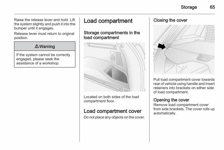
Load compartment
Storage compartments in theload compartment
Located on both sides of the loadcompartment floor.
Load compartment coverDo not place any objects on the cover.
Closing the cover
Pull load compartment cover towardsrear of vehicle using handle and insertretainers into brackets on either sideof load compartment.
Opening the coverRemove load compartment coverfrom side brackets. The cover rolls upautomatically.

66 Storage
Removing the cover
Open load compartment cover. Pullsocket on either side of cover towardscentre of vehicle, lift and removecover from the side guides.Fit in reverse order.
Rear floor storage cover
To access the rear floor storagecompartment, pull floor cover handleupwards.
Depending on version, to access therear floor storage compartment, pushboth levers on the floor cover towardsthe handle and pull up the cover bythe handle.

Storage 67
Where present, hang the hook to theupper part of the tailgate opening.
Caution
Only use the hook for hanging upthe rear floor cover and the heightadjustable cover.
Caution
Do not allow objects to protrudeabove the top of the rear floorstorage compartment, to avoiddamage to the storage area andthe load compartment floor.
Jack and vehicle tools 3 171.Tyre repair kit 3 177.Temporary spare wheel 3 183.
Lashing eyes
The lashing eyes are designed tosecure items against slippage, e.g.using lashing straps or a luggage floornet.Two additional lashing eyes arelocated in front of the rear seats forfitting a safety net 3 69.Designed for carrying small, lightitems only, a luggage floor net helpskeep loads from moving during sharpturns or quick starts and stops.To install: attach the four net hooks tothe lashing eyes mounted on the loadcompartment floor.
Cargo managementsystemThe FlexOrganizer is a flexiblesystem for dividing the loadcompartment or securing loads.

68 Storage
The system consists of:■ adapters,■ variable partition net,■ mesh pockets,■ hooks.The components are fitted in twoguide rails in the side walls of the loadcompartment using adapters andhooks.
Variable partition net
Insert an adapter into each rail: foldopen the handle plate, insert adapterinto upper and lower groove of railand move to required position.Turn handle plate upwards to lock theadapter. The rods of the net must beextended before inserting into theadapters: pull out all of the end piecesand lock by rotating clockwise.To install, push rods together a littleand insert into the relevant openingsin the adapters. The longer rod mustbe inserted into the upper adapter.
To remove, press the net rod togetherand remove from the adapters. Foldopen the adapter handle plate,disengage from lower groove andthen from upper groove.
Hooks and mesh pocket
Insert the hooks in the desiredposition in the rails: insert the hook inthe upper groove on the rail and pressin the lower groove.The mesh pocket can be hung fromthe hooks.

Storage 69
Safety netThe safety net can be mountedbehind the rear seats or, if the rearseat backrests are folded down, infront of the rear seats.Passengers must not be transportedbehind the safety net.
Installation
There are four installation openings inthe roof frame, two located in front ofand two behind the rear seats.When fitting behind the rear seats,remove the load compartment cover3 65.
When fitting in front of the rear seats,push head restraints of the rear seatsdown and fold down rear seatbackrests 3 38.Open aperture covers on the roofframe and insert top corners of safetynet into large apertures in roof frameand secure by sliding them into thesmaller apertures.
In front of and behind the rear seatson both sides of the vehicle are thehook holders (lashing eyes) for thelower strap hooks. Hang strap hooksin the two lashing eyes. Pull on thestraps to take up any slack.
9 Warning
Do not stack loads higher than theupper end of the safety net.Avoid applying excessive force tothe safety net or hanging heavyitems from it.Do not place loads behind thesafety net which have sharp edgesthat could pass through the net inthe event of heavy braking, forexample.
RemovalLoosen straps by pulling up strapadjusters and remove the strap hooksfrom the lashing eyes. Pull topcorners of safety net from the smallerapertures into the larger aperturesand remove.
Warning triangleStow the warning triangle below thefloor cover in the load compartment.

70 Storage
First aid kitStow the first aid kit below the floorcover in the load compartment.
Fire extinguisherStow the fire extinguisher securely inthe load compartment.
Roof rack systemRoof rackFor safety reasons and to avoiddamage to the roof, the vehicleapproved roof rack system isrecommended. For furtherinformation contact a workshop.Fasten the roof rack to the roof railsfollowing the instructions thataccompany the system, ensuring thatthe roof load is evenly distributed overthe side or cross rails.Loads must not be placed on the roofsurface. To prevent damage or loss,check frequently that roof loads aresecurely fastened.Driving with a roof load affects thevehicle centre of gravity; drivecarefully in crosswinds and do notdrive at high speeds.Remove the roof rack when not inuse.
Loading information■ Heavy objects in the load
compartment should be evenlydistributed and placed as farforward as possible. Ensure thebackrests are securely engaged. Ifobjects can be stacked, the heavierobjects should be placed at thebottom.With rear seats in the foldedposition, or with safety net installedbehind rear seats, objects must notbe stacked higher than the seatbackrests.
■ Secure objects with lashing strapsattached to lashing eyes 3 67.
■ Secure loose objects in the loadcompartment using FlexOrganizeror a luggage floor net to preventsliding.
■ When transporting objects in theload compartment, fit the safety net3 69. The backrests of the rearseats must not be angled forward.

Storage 71
■ Do not allow the load to protrudeabove the upper edge of thebackrests.
■ Do not place any objects on theload compartment cover or theinstrument panel, and do not coverthe sensor on top of the instrumentpanel.
■ The load must not obstruct theoperation of the pedals, electricalparking brake and gear selector, orhinder the freedom of movement ofthe driver. Do not place anyunsecured objects in the interior.
■ Do not drive with an open loadcompartment.
9 Warning
Always make sure that the load inthe vehicle is securely stowed.Otherwise objects can be thrownaround inside the vehicle andcause personal injury or damageto the load or car.
■ The payload is the differencebetween the permitted gross
vehicle weight (see identificationplate 3 195) and the EC kerbweight.To calculate the EC kerb weight,enter the data for your vehicle in theWeights table at the front of thismanual.The EC kerb weight includesweights for the driver (68 kg),luggage (7 kg) and all fluids (tank90 % full).Optional equipment andaccessories increase the kerbweight.
■ Driving with a roof load increasesthe sensitivity of the vehicle tocross-winds and has a detrimentaleffect on vehicle handling due tothe vehicle's higher centre ofgravity. Distribute the load evenlyand secure it properly with retainingstraps. Adjust the tyre pressure andvehicle speed according to the loadconditions. Check and retighten thestraps frequently.Do not drive faster than 75 mph.
The permissible roof load is100 kg. The roof load is thecombined weight of the roof rackand the load.

72 Instruments and controls
Instruments andcontrols
Controls ....................................... 72Warning lights, gauges and indi‐cators ........................................... 79Information displays ..................... 91Vehicle messages ........................ 98Trip computer ............................. 100
ControlsSteering wheel adjustment
Unlock lever, adjust steering wheel,then engage lever and ensure it isfully locked.Do not adjust steering wheel unlessvehicle is stationary and steeringwheel lock has been released.
Steering wheel controls
The Infotainment system and aconnected mobile phone can beoperated via the controls on thesteering wheel.Further information is available in theInfotainment system instructionmanual.

Instruments and controls 73
Horn
Press j.
Windscreen wiper/washerWindscreen wiper
& = fast% = slow$ = timed interval wiping or
automatic wiping with rainsensor
§ = off
For a single wipe when thewindscreen wiper is off, press thelever down.Do not use if the windscreen is frozen.Switch off in car washes.
Adjustable wiper interval
To set the wiping interval to a valuebetween 1 and 10 seconds:■ Switch on ignition.■ Push lever down from position §.■ Wait until wiping frequency reaches
the desired interval.■ Set lever to position $.The interval remains stored until thenext change or until the ignition isswitched off. Switching the ignition onand moving the lever to $ sets theinterval to 3.5 seconds.

74 Instruments and controls
In this mode, wiping frequency is alsoaffected by vehicle speed. As vehiclespeed increases, wiping will becomemore frequent.
Automatic wiping with rain sensor
$ = automatic wiping with rainsensor
The rain sensor detects the amount ofwater on the windscreen andautomatically regulates the frequencyof the windscreen wiper.
The wiper operates for one cycle tocheck the system when the key isturned to ignition switch positionACC.To turn wiper off, move lever toposition §.
Keep the rain sensor area clean byactivating the windscreen washersystem.
Windscreen and headlightwasher
Pull lever. Washer fluid is sprayedonto the windscreen.If the lever is held longer, the wiperoperates for two cycles after the leverhas been released and once moreafter a 3 second delay.If the headlights are on, washer fluidis also sprayed onto the headlights.The headlight washer system canonly be operated again after a shortdelay. If washer fluid level is low thenthis delay is increased.
Instruments and controls 75
Control indicator G illuminates in theinstrument cluster when the washerfluid level is low.
Wiper activated lightingWith light switch in the AUTOposition, when the windscreen wiperis operated for 8 cycles or more theexterior lights illuminateautomatically.
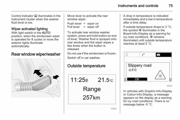
Rear window wiper/washer
Move lever to activate the rearwindow wiper:Push lever = wiper onPull lever = wiper off
To activate rear window washersystem, press and hold button on endof lever. Washer fluid is sprayed ontorear window and the wiper wipes afew times when the button isreleased.Do not use if the windscreen is frozen.Switch off in car washes.
Outside temperature
A drop in temperature is indicatedimmediately and a rise in temperatureafter a time delay.If outside temperature drops to 3 °C,the symbol : illuminates in theBoard-Info-Display as a warning foricy road conditions. : remainsilluminated until outside temperaturereaches at least 5 °C.
In vehicles with Graphic-Info-Displayor Colour-Info-Display, a messageappears on the display as a warningfor icy road conditions. There is nomessage below -5 °C.

76 Instruments and controls
9 Warning
The road surface may already beicy even though the displayindicates a few degrees above0 °C.
Clock
Date and time are shown in theInfo-Display.Board-Info-Display 3 91.
Graphic-Info-Display,Colour-Info-Display 3 93.
Automatic time synchronisation
Board-Info-Display
The RDS (Radio Data System) signalof most VHF transmittersautomatically sets the time, identifiedby } in the display.Some RDS transmitters do not senda correct time signal. In such cases,switch off automatic timesynchronisation and set the timemanually.

Instruments and controls 77
Deactivate (Clock Sync.Off) oractivate (Clock Sync.On) automatictime synchronisation with the arrowbuttons on the Infotainment system.To set date and time manually, selectthe menu item for time and datesetting from the Settings menu andmake the desired setting. The valueready for modification is marked witharrows. Use the arrow buttons tomake the required setting. The settingis saved when the menu item isexited.To correct time with the help of RDS,select the menu item for timesynchronisation from the Settingsmenu and make the desired setting.Board-Info-Display 3 91.
Graphic-Info-Display, Colour-Info-Display
With the navigation system, date andtime are set automatically uponreceipt of a GPS satellite signal. If thedisplayed time does not match localtime, it can be corrected manually orautomatically by receiving an RDStime signal.Some RDS transmitters do not senda correct time signal. In such cases,switch off automatic timesynchronisation and set the timemanually.
To set date and time manually, selectmenu item Time, Date from theSettings menu. The menu isdisplayed. Select the menu itemsrequired and make the desiredsetting.To correct time with the help of RDS,select menu item Synchron. clockautomatical. from the Time, Datemenu. The box in front of Synchron.clock automatical. will be checked.Graphic-Info-Display,Colour-Info-Display 3 93.
Power outletsThe socket for the cigarette lightercan be used to connect electricalaccessories.

78 Instruments and controls
A 12 Volt power outlet is located in therear centre console and on the right-hand side of the load compartment.Pull the cap out to use the accessorysocket, and replace the cap when notin use.Do not exceed the maximum powerconsumption of 120 watts.Operational with ignition switch inpositions ACC or ON. Use ofaccessory sockets while the engine isnot running will discharge the battery.
Electrical accessories that areconnected must comply with theelectromagnetic compatibilityrequirements laid down inDIN VDE 40 839.Do not connect any current-deliveringaccessories, e.g. electrical chargingdevices or batteries.Do not damage the outlet by usingunsuitable plugs.Stop-start system 3 123.
Cigarette lighter
Depending on the equipment, thecigarette lighter may be located in thefront centre console or beneath thecupholder.Slide the cupholder tray back toaccess the cigarette lighter.With ignition switch in position ACC orON, press in cigarette lighter. Heatingswitches off automatically once theelement is glowing. Pull out lighter.
Ashtrays
Caution
To be used only for ash and not forcombustible rubbish.
The portable front ashtray can beplaced in the front console cupholder.To open: gently lift up lid. Illuminatesdepending on outside light conditions.To empty: rotate upper part of ashtrayanticlockwise and remove. After use,close lid firmly.

Instruments and controls 79
To replace battery: remove screw onashtray lid and replace with CR 2032(or equivalent) battery.
Warning lights, gaugesand indicatorsInstrument clusterIn some versions, the needles of theinstruments briefly rotate to the endposition when the ignition is switchedon.
Speedometer
Indicates vehicle speed.
OdometerThe odometer display is located in thecentre of the instrument cluster.
The bottom line displays the recordeddistance in miles.
Trip odometerThe top line displays the recordeddistance since the last reset.There are two independent tripodometers. Press the trip odometerbutton once to toggle betweenTrip A and Trip B.

80 Instruments and controls
To reset, press and hold the tripodometer button for a few secondswith the ignition on.
Tachometer
Displays the engine speed.Drive in a low engine speed range foreach gear as much as possible.
Caution
If the needle is in the red warningzone, the maximum permittedengine speed is exceeded. Engineat risk.
Fuel gauge
Displays the fuel level in the tank.Control indicator Y illuminates if thelevel in the tank is low. Refuelimmediately 3 143.Never run the tank dry. Erratic fuelsupply can cause catalytic converterto overheat 3 127.Diesel engines: if the tank has beenrun dry, bleed the fuel system 3 157.Because of the fuel remaining in thetank, the top-up quantity may be lessthan the specified tank capacity3 204.
Transmission display
Displays the mode or selected gearwith automatic transmission.P = park positionR = reverse gearN = neutralD = drive position (automatic
mode)1-6 = selected gear in manual mode
Control indicatorsThe control indicators described arenot present in all vehicles. Thedescription applies to all instrument

Instruments and controls 81
versions. Depending on theequipment, the position of the controlindicators may vary.When the ignition is switched on,most control indicators will illuminatebriefly as a functionality test.The control indicator colours mean:red = danger, important
reminderyellow = warning, information, faultgreen = confirmation of activationblue = confirmation of activation
Control indicators on theinstrument panel
k illuminates red.Front passenger seat belt reminder3 41.* illuminates yellow.The front passenger airbag isdeactivated 3 45.
9 Danger
Risk of fatal injury for a child usinga child restraint system togetherwith activated front passengerairbag.Risk of fatal injury for an adultperson with deactivated frontpassenger airbag.

82 Instruments and controls
Control indicators in the instrument cluster

Instruments and controls 83
Turn signalO illuminates or flashes green.The relevant control indicator flasheswhen the turn signal is switched on3 108.Rapid flashing: failure of a turn signalbulb or the associated fuse or failureof a turn signal light on trailer.Both control indicators flash when thehazard warning flashers are active3 107.Bulb replacement 3 158, Fuses3 164.Turn signals 3 108.
Seat belt reminderSeat belt reminder for frontseatsX for driver's seat illuminates orflashes red.k for front passenger's seatilluminates or flashes red, when theseat is occupied.
When the engine is running, if seatbelt is not engaged, the controlindicator will flash for 100 secondsthen illuminate until seat belt isfastened.If vehicle speed exceeds 14 mph, thecontrol indicator will flash for100 seconds along with a warningchime and remains illuminated untilseat belt is fastened.Fastening the seat belt 3 40.Front passenger seat belt reminder k3 41.
Airbag and belt tensionersv illuminates red.When the ignition is switched on, vflashes briefly. If it does not flash,stays lit or flashes during driving,there is a fault in the airbag system.Seek the assistance of a workshop.The airbags and belt pretensionersmay fail to trigger in the event of anaccident.Deployment of the belt pretensionersor airbags is indicated by continuousillumination of v.
9 Warning
Have the cause of the faultremedied immediately by aworkshop.
Belt pretensioners, airbag system3 40, 3 43.
Charging systemp illuminates red.Illuminates when the ignition isswitched on and extinguishes shortlyafter the engine starts. If it does notilluminate, seek the assistance of aworkshop.
Illuminates when the engine isrunningStop vehicle and switch off engine.Battery is not charging. Enginecooling may be interrupted. Thebrake servo unit may cease to beeffective.

84 Instruments and controls
Interrupt your journey immediately.Remove key and check drive beltcondition and tensioning beforeseeking the assistance of aworkshop.
Malfunction indicator lightZ illuminates or flashes yellow.Illuminates when the ignition isswitched on and extinguishes shortlyafter the engine starts. If it does notilluminate, seek the assistance of aworkshop.Can illuminate briefly when driving;this is normal and does not indicate asystem fault.
Illuminates when the engine isrunningFault in the emission control system.The permitted emission limits may beexceeded. Fuel economy and vehicledriveability may be impaired. Seekthe assistance of a workshopimmediately.
Control indicator Z also illuminates ifthere is a fault in the diesel particlefilter 3 126 or with the automatictransmission 3 130. Seek theassistance of a workshop as soon aspossible.Ensure the fuel filler cap is screwed incompletely 3 143.
Flashes when the engine isrunningFault that could lead to catalyticconverter damage 3 127. Ease up onthe accelerator until the flashingstops. Seek the assistance of aworkshop immediately.
Service vehicle soong illuminates yellow.Illuminates when the engine isrunning to indicate a fault in theengine or transmission electronics.The electronics switch to anemergency running programme, fuelconsumption may be increased andvehicle handling may be impaired.
In some cases, the fault can beeliminated by switching the engine offand back on again. If g illuminatesagain after restarting the engine, thevehicle may need a service.Have the cause of the fault eliminatedby a workshop.
Brake systemR illuminates red.Illuminates when the ignition isswitched on and extinguishes shortlyafter the engine starts. If it does notilluminate, stop and seek theassistance of a workshop.If it stays lit while the engine isrunning, the brakes do not operate asnormal, or leaks are found in thebrake system, do not attempt to drivethe vehicle. Have the vehicle towed toa workshop for inspection and repair.
9 Warning
Stop. Do not continue yourjourney. Consult a workshop.
Instruments and controls 85
Illuminates when engine is running iffluid level for brake hydraulics is toolow 3 154.Brake system 3 134.
Electrical parking brakem illuminates or flashes red.When the engine is started, milluminates briefly. If it does notilluminate, seek the assistance of aworkshop.
IlluminatesElectrical parking brake is applied3 135.
FlashesElectrical parking brake is not fullyapplied or released.Switch on ignition, depress brakepedal and attempt to reset the systemby first releasing and then re-applyingthe electrical parking brake.If m remains flashing, do not driveand seek the assistance of aworkshop.
Electrical parking brakefaultj illuminates yellow.When the ignition is switched on, jilluminates briefly. If it does notilluminate, seek the assistance of aworkshop.
IlluminatesElectrical parking brake is operatingwith degraded performance 3 135.
9 Warning
Have the cause of the faultremedied immediately by aworkshop.
Antilock brake system(ABS)u illuminates yellow.The system is ready for operationwhen the control indicatorextinguishes.
If the control indicator does notilluminate when the ignition isswitched on, stays lit or illuminatesduring driving, there is a fault in theABS. The brake system remainsoperational but without ABSregulation.If control indicator u illuminatesduring driving along with brakesystem control indicator R, there is aserious fault in the brake system.Have the system checkedimmediately by a workshop.Antilock brake system 3 134.
Upshift[ illuminates green.Upshifting is recommended for fuelsaving purposes.
All wheel driveB illuminates or flashes yellow.Illuminates briefly when the ignition isswitched on. If it does not illuminate,seek the assistance of a workshop.

86 Instruments and controls
Flashes briefly when the engineis runningThe system is temporarily disabled.
Flashes continuously when theengine is runningSystem fault. Seek the assistance ofa workshop immediately.All wheel drive 3 132.
Descent control systemu illuminates yellow and/or green.Both the yellow and green controlindicators illuminate briefly when theignition is switched on.
GreenIlluminates when system is ready foroperation.Flashes during driving when systemis in operation, after pressing the ubutton.
YellowFlashes to indicate system is notready for conditions to operate.
Illuminates to indicate there is a faultin the system.If it flashes or illuminates duringdriving, friction material needs to cooldown: drive the vehicle withoutbraking as much as possible.Descent control system 3 138.
Power steering2 illuminates yellow.When the ignition is switched on, 2illuminates briefly. If it does notilluminate, stays lit or illuminatesduring driving, there is a fault in thesystem. Seek the assistance of aworkshop.Power steering 3 121.
Ultrasonic parking assistr illuminates yellow.Fault in systemorFault due to sensors that are dirty orcovered by ice or snowor
Interference due to external sourcesof ultrasound. Once the source ofinterference is removed, the systemwill operate normally.Have the cause of the fault in thesystem remedied by a workshop.Ultrasonic parking assist 3 140.
Electronic Stability Controlb illuminates or flashes yellow.When the engine is started, billuminates briefly. If it does notilluminate, seek the assistance of aworkshop.
IlluminatesFault in the system. Continued drivingis possible. Driving stability, however,may deteriorate depending on roadsurface conditions.Have the cause of the fault remediedby a workshop.

Instruments and controls 87
FlashesThe system is actively engaged.Engine output may be reduced andthe vehicle may be brakedautomatically to a small degree.Electronic Stability Control 3 137.
Electronic Stability Controlofft illuminates yellow.When the ignition is switched on, tilluminates briefly. If it does notilluminate, seek the assistance of aworkshop.Illuminates when ESC has beenswitched off manually by pressingbutton t on the centre console.Electronic Stability Control 3 137.
Engine coolanttemperatureW illuminates red.
When the engine is started, Willuminates briefly. If it does notilluminate, seek the assistance of aworkshop.
Illuminates when the engine isrunningStop vehicle and switch off engine.
Caution
Coolant temperature too high.
Check coolant level 3 152.If there is sufficient coolant, seek theassistance of a workshop.
Preheating! illuminates yellow.Preheating is activated. Onlyactivates when outside temperatureis low.If it illuminates during driving or if theengine cannot be started, seek theassistance of a workshop as soon aspossible.Starting the engine 3 122.
Diesel particle filter% illuminates or flashes yellow.The diesel particle filter requirescleaning.Continue driving until %extinguishes.
Illuminates during drivingThe diesel particle filter is full. Startcleaning process as soon aspossible.
Flashes during drivingThe maximum filling level of the filteris reached. Start cleaning processimmediately to avoid damage to theengine.Diesel particle filter 3 126, Stop-startsystem 3 123.
Engine oil pressureI illuminates red.

88 Instruments and controls
Illuminates when the ignition isswitched on and extinguishes shortlyafter the engine starts. If it does notilluminate, seek the assistance of aworkshop.
Illuminates when the engine isrunning
Caution
Engine lubrication may beinterrupted. This may result indamage to the engine and/orlocking of the drive wheels.
1. Depress clutch.2. Select neutral gear, set selector
lever to N.3. Move out of the flow of traffic as
quickly as possible withoutimpeding other vehicles.
4. Switch off ignition.
9 Warning
When the engine is off,considerably more force is neededto brake and steer. During anAutostop the brake servo unit willstill be operational.Do not remove key until vehicle isstationary, otherwise the steeringwheel lock could engageunexpectedly.
Check oil level before seeking theassistance of a workshop 3 151.
Low engine oil levelS illuminates yellow.When the ignition is switched on, Silluminates briefly. If it does notilluminate, seek the assistance of aworkshop.
Illuminates during drivingOil level is low: top up oil to specifiedlevel 3 151.
Change engine oilEngine oil life monitorC illuminates yellow.When the engine is started, Cilluminates briefly. If it does notilluminate, seek the assistance of aworkshop.The engine oil life monitor lets youknow when to change the oil. Controlindicator C illuminates to indicatethat engine oil life has beendiminished and the oil needschanging.Based on driving conditions, theinterval at which an oil change will beindicated can vary considerably.Change oil within 600 miles. Enginepower may be decreased.Once the engine oil has beenchanged 3 151, the engine oil lifemonitor needs to be reset. Seek theassistance of a workshop.
Fuel economy modes illuminates green.

Instruments and controls 89
Illuminates when fuel ecomony modeis switched on 3 129.
Low fuelY illuminates yellow.When the engine is started, Yilluminates briefly. If it does notilluminate, seek the assistance of aworkshop.Illuminates during driving when fuellevel in tank is too low. Refuelimmediately 3 143.Never run the tank dry. Erratic fuelsupply can cause catalytic converterto overheat 3 127.Diesel engines: if the tank has beenrun dry, bleed the fuel system 3 157.Fuel tank capacity 3 204.Catalytic converter 3 127.
Drain fuel filterU illuminates yellow.Illuminates when water level in dieselfuel filter exceeds a specified level.
Residual water in the diesel fuel filtermust be drained 3 157. Seek theassistance of a workshop as soon aspossible.
Immobiliserd illuminates red.When the engine is started, dilluminates briefly. If it does notilluminate, seek the assistance of aworkshop.Illuminates to indicate a fault in theimmobiliser system. The enginecannot be started.Electronic immobiliser 3 26.
Reduced engine power# illuminates yellow.Illuminates in conjunction with controlindicator g, the vehicle needs aservice. Move out of the flow of trafficas quickly as possible withoutimpeding other vehicles, stop theengine and restart after 10 seconds.The engine power is limited. Consulta workshop.
Apply footbrake- illuminates yellow.Brake pedal needs to be depressedto release the electrical parking brake3 135.Clutch pedal needs to be depressedto restart the engine.Stop-start system 3 123.
High beamC illuminates blue.Illuminated when high beam is on andduring headlight flash 3 106.
Automatic headlightlevelling systemq illuminates yellowIlluminates during driving to indicate afault that requires immediateattention. Seek the assistance of aworkshop as soon as possible.Automatic headlight rangeadjustment 3 106.

90 Instruments and controls
Fog light> illuminates green.Illuminates when the front fog lightsare switched on 3 108.
Rear fog lightr illuminates yellow.Illuminates when the rear fog light isswitched on 3 109.
Cruise controlm illuminates yellow or green.
Illuminates yellowThe system is ready for operation.
Illuminates greenA certain speed is stored.Cruise control 3 139.
Speed warningà illuminates yellow.In vehicles equipped with theoverspeed warning light, whenvehicle speed exceeds 75 mph,
control indicator à flashes,accompanied by a warning chime, towarn the driver to reduce speed asappropriate.
Trailer indicatorá illuminates green.Illuminates when a trailer isconnected to the vehicle 3 145.
Bonnet open/ illuminates red.Illuminates when the bonnet is open.Stop-start system 3 123.
Door open( illuminates red.Illuminates when a door is open or notsecurely latched.
Tailgate open1 illuminates red.Illuminates when tailgate is open ornot securely latched 3 22.
Anti-theft alarm systema illuminates yellow.Illuminates when alarm systemmonitoring of the passengercompartment and vehicle inclinationhas been switched off with buttona in the roof lining.Anti-theft alarm system 3 24.

Instruments and controls 91
Information displaysBoard-Info-DisplayThe Info-Display is located in theinstrument panel above theInfotainment system.
Info-Display indicates:■ time 3 76■ outside temperature 3 75■ date 3 76■ Infotainment system - see
Infotainment system instructionmanual
The Info-Display is located in theinstrument panel above theInfotainment system.An F in the display indicates a fault.Have the cause of the fault remediedby a workshop.Trip computer, Board-Info-Display3 100.
Selecting functionsFunctions and settings of theInfotainment system can be accessedvia the Info-Display.Functions are selected and executedin the menu on the display using thearrow buttons on the Infotainmentsystem or the left adjuster wheel onthe steering wheel.If a check control warning messageappears on the Info-Display, thedisplay is blocked from otherfunctions. Acknowledge the messageby pressing the OK button or the leftadjuster wheel. If there are severalwarning messages, acknowledgethem one at a time.Check control 3 99.
Select using the Infotainment systembuttons
In the Settings menu, use the OKbutton to call up the required function.Use the arrow buttons to changesettings.In the BC menu, use the OK button tocall up the required function. Use theOK button to operate the stop watchor restart measurement andcalculation.

92 Instruments and controls
Select using the left adjuster wheel onthe steering wheel
Turn the adjuster wheel to call up therequired function.Press the adjuster wheel to open theBC menu, to select marked items andconfirm commands. In the BC menupress to operate the stop watch orrestart measurement and calculation.
System settings
Press the Settings button of theInfotainment system. Menu itemAudio then opens.Call up System with the left arrowbutton and select with the OK button.The first function of the System menuis highlighted. Some of the functionsappear on the display in anabbreviated form.The functions are displayed in thefollowing order:■ Time synchronisation■ Time, setting hours
■ Time, setting minutes■ Date, setting day■ Date, setting month■ Date, setting year■ Ignition logic■ Language selection■ Setting units of measure
Automatic time synchronisation
The RDS (Radio Data System) signalof most VHF transmittersautomatically sets the time, identifiedby } in the display.

Instruments and controls 93
Some transmitters do not send acorrect time signal. In such cases,switch off automatic timesynchronisation and set the timemanually.Deactivate (Clock Sync.Off) oractivate (Clock Sync.On) automatictime synchronisation with the arrowbuttons.
Setting date and time
To set date and time manually, selectthe menu item for time and datesettings and make the desiredsetting.
The value ready for modification ismarked with arrows. Use the arrowbuttons to make the required setting.The setting is saved when the menuitem is exited.
Ignition logicSee Infotainment system instructionmanual.
Language selection
The display language for somefunctions can be selected.Select the required language with thearrow buttons.
Setting units of measure
Select the required unit ofmeasurement with the arrow buttons.
Graphic-Info-Display,Colour-Info-DisplayDepending on the vehicleconfiguration the vehicle has aGraphic-Info-Display orColour-Info-Display. TheInfo-Display is located in theinstrument panel above theInfotainment system.

94 Instruments and controls
Info-Display indicates:■ time 3 76■ outside temperature 3 75■ date 3 76■ Infotainment and navigation
systems - see Infotainment systeminstruction manual
■ system settingsThe Info-Display is located in theinstrument panel above theInfotainment system. TheGraphic-Info-Display presents theinformation in monochrome. TheColour-Info-Display presents theinformation in colour.
The type of information and how it isdisplayed depends on the equipmentof the vehicle and the settings of thetrip computer and Infotainmentsystem. Some information appearson the display in an abbreviated form.An F in the display indicates a fault.Have the cause of the fault remediedby a workshop.Trip computer, Graphic-Info-Display,Colour-Info-Display 3 101.
Selecting functionsThe functions and settings of theInfotainment system can be accessedvia the Info-Display.Functions are selected and executedin the menu on the display using thearrow buttons and the centralmultifunction knob on theInfotainment system or the leftadjuster wheel on the steering wheel.If a check control warning messageappears on the Info-Display, thedisplay is blocked from otherfunctions. Acknowledge the messageby pressing an arrow button, themultifunction knob or the left adjuster
wheel. If there are several warningmessages, acknowledge them one ata time.Check control 3 99.
Select using the Infotainmentsystem buttons
Select a function via the Infotainmentsystem arrow buttons. The menu ofthe selected function is displayed.
Select using the centralmultifunction knobThe multifunction knob is the centralcontrol element for the menus:

Instruments and controls 95
Turn■ To mark a menu option■ To set a numeric value or to display
a menu optionPress■ To select or activate the marked
option■ To confirm a set value■ To switch a system function on/offTo exit a menu, turn the multifunctionknob left or right to Return or Main andselect.
Select using the left adjusterwheel on the steering wheel
Turn the adjuster wheel to call up therequired function.Press the adjuster wheel to selectmarked items and confirmcommands. Press to operate the stopwatch or restart measurement andcalculation.Trip computer 3 101.
Function areas
For each function area there is a mainpage (Main), which is selected at thetop edge of the display:■ Audio,■ Navigation,■ Telephone,■ Trip computer.See Infotainment system instructionmanual for further information.

96 Instruments and controls
System settings
The settings are accessed via theSettings menu. Press the Main button(not found on all Infotainmentsystems) on the Infotainment system,to call up main display. Press theSettings button. On InfotainmentSystem CD 30, ensure no menu hasbeen selected. The Settings menu isdisplayed.The functions are displayed in thefollowing order:■ Time, Date■ Language■ Units
■ Contrast■ Day / Night■ Ignition logic
Setting date and time
With the navigation system, date andtime are set automatically uponreceipt of a GPS satellite signal. If thedisplayed time does not match localtime, it can be corrected manually orautomatically by receiving an RDStime signal.
Some RDS transmitters do not senda correct time signal. In such cases,switch off automatic timesynchronisation and set the timemanually.To set date and time manually, selectmenu item Time, Date from theSettings menu. The menu isdisplayed. Select the menu itemsrequired and make the desiredsetting.To correct time with the help of RDS,select menu item Synchron. clockautomatical. from the Time, Datemenu. The box in front of Synchron.clock automatical. will be checked.

Instruments and controls 97
Language selection
The display language for somefunctions can be selected. Selectmenu item Language from theSettings menu. The availablelanguages are displayed.
Select the desired language.Selections are indicated by a 6 infront of the menu item.In systems with voice output, whenthe language setting of the display ischanged, the system will ask whetherthe announcement language shouldalso be changed – see Infotainmentsystem instruction manual.
Setting units of measure
Select menu item Units from theSettings menu. The available unitsare displayed. Select the desired unit.Selections are indicated by a o infront of the menu item.

98 Instruments and controls
Adjusting contrast(Graphic-Info-Display)
Select menu item Contrast from theSettings menu. The menu isdisplayed. Confirm the requiredsetting.
Setting display modeThe display can be adjusted to suitthe lighting conditions:Select menu item Day / Night from theSettings menu. The options aredisplayed.Automatic; adapted based on vehiclelighting.
Always day design; black or colouredtext on a light background.Always night design; white orcoloured text on a dark background.Selections are indicated by a o infront of the menu item.
Ignition logicSee Infotainment system instructionmanual.
Vehicle messagesWarning chimesWhen starting the engine orwhilst drivingOnly one warning chime will sound ata time.The warning chime regardingunfastened seat belts has priorityover any other warning chime.■ If seat belt is not fastened.■ When operating the turn and lane-
change signals.■ When the vehicle is being driven
and the electrical parking brake isapplied 3 135.
■ When releasing the electricalparking brake without applying thefoot brake 3 89.
■ If there is a fault in the brakingsystem 3 84.

Instruments and controls 99
■ If the parking assist detects anobject 3 140.
■ In vehicles equipped with engineoverspeed warning; when vehiclespeed exceeds 75 mph 3 90.
When the vehicle is parked and/or the driver's door is opened■ When the key is in the ignition
switch.■ With exterior lights on.
Tyre pressureCheck control
In vehicles with tyre pressuremonitoring system, if low tyrepressures are detected, relevantinformation appears on theinformation display.Reduce speed and check tyrepressure at the next opportunity.Tyre pressure monitoring system3 174.Check tyre pressures 3 174, 3 205.
If there is a considerable loss ofpressure, a corresponding messageappears indicating the relevant tyre.
Steer out of the flow of traffic asquickly as possible withoutendangering other vehicles. Stop andcheck the tyres. Mount the sparewheel 3 180, 3 183.Tyre pressure monitoring system3 174.

100 Instruments and controls
Trip computerTrip computer in Board-Info-DisplayThe trip computer providesinformation on driving data, which iscontinually recorded and evaluatedelectronically. Access trip computervehicle data by pressing the BCbutton on the Infotainment system orthe left adjuster wheel on the steeringwheel.Some of the functions appear on thedisplay in an abbreviated form. Oncea function has been selected, thesubsequent rows of the trip computerfunction are displayed.The functions are displayed in thefollowing order:■ Instantaneous consumption■ Average consumption■ Effective consumption■ Average speed■ Distance travelled
■ Range■ Stop watchBoard-Info-Display 3 91.
Instantaneous consumption
Display of the instantaneousconsumption.Display changes depending onspeed:Display in gal/h = below 8 mphDisplay in miles/gal = above 8 mph
Average consumptionDisplay of average consumption. Themeasurement can be reset at anytime.
Effective consumptionDisplay of the amount of fuelconsumed. The measurement can bereset at any time.
Average speedDisplay of average speed. Themeasurement can be reset at anytime.Stoppages in the journey with theignition off are not included in thecalculations.
Distance travelledDisplay of distance travelled. Themeasurement can be reset at anytime.
RangeRange is calculated from current fueltank content and instantaneousconsumption. The display showsaverage values.
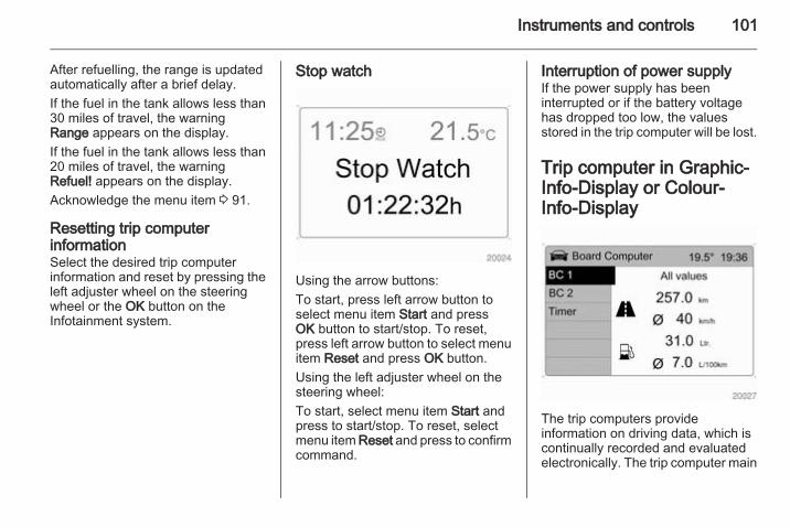
Instruments and controls 101
After refuelling, the range is updatedautomatically after a brief delay.If the fuel in the tank allows less than30 miles of travel, the warningRange appears on the display.If the fuel in the tank allows less than20 miles of travel, the warningRefuel! appears on the display.Acknowledge the menu item 3 91.
Resetting trip computerinformationSelect the desired trip computerinformation and reset by pressing theleft adjuster wheel on the steeringwheel or the OK button on theInfotainment system.
Stop watch
Using the arrow buttons:To start, press left arrow button toselect menu item Start and pressOK button to start/stop. To reset,press left arrow button to select menuitem Reset and press OK button.Using the left adjuster wheel on thesteering wheel:To start, select menu item Start andpress to start/stop. To reset, selectmenu item Reset and press to confirmcommand.
Interruption of power supplyIf the power supply has beeninterrupted or if the battery voltagehas dropped too low, the valuesstored in the trip computer will be lost.
Trip computer in Graphic-Info-Display or Colour-Info-Display
The trip computers provideinformation on driving data, which iscontinually recorded and evaluatedelectronically. The trip computer main
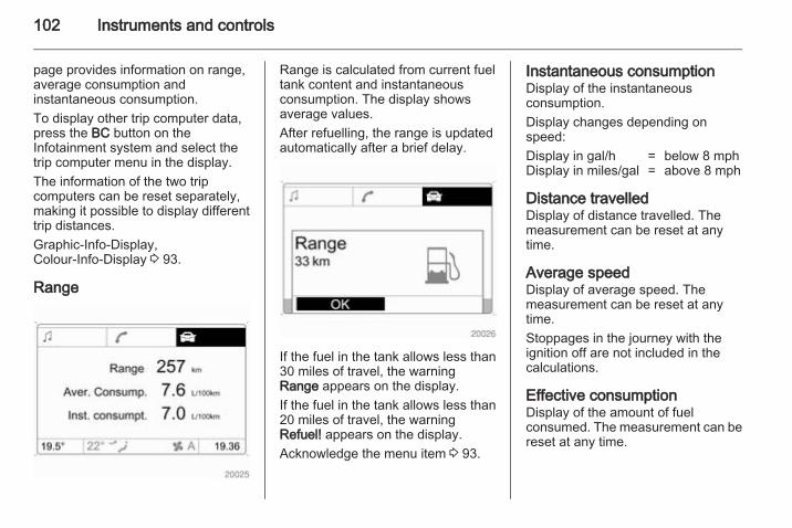
102 Instruments and controls
page provides information on range,average consumption andinstantaneous consumption.To display other trip computer data,press the BC button on theInfotainment system and select thetrip computer menu in the display.The information of the two tripcomputers can be reset separately,making it possible to display differenttrip distances.Graphic-Info-Display,Colour-Info-Display 3 93.
Range
Range is calculated from current fueltank content and instantaneousconsumption. The display showsaverage values.After refuelling, the range is updatedautomatically after a brief delay.
If the fuel in the tank allows less than30 miles of travel, the warningRange appears on the display.If the fuel in the tank allows less than20 miles of travel, the warningRefuel! appears on the display.Acknowledge the menu item 3 93.
Instantaneous consumptionDisplay of the instantaneousconsumption.Display changes depending onspeed:Display in gal/h = below 8 mphDisplay in miles/gal = above 8 mph
Distance travelledDisplay of distance travelled. Themeasurement can be reset at anytime.
Average speedDisplay of average speed. Themeasurement can be reset at anytime.Stoppages in the journey with theignition off are not included in thecalculations.
Effective consumptionDisplay of the amount of fuelconsumed. The measurement can bereset at any time.

Instruments and controls 103
Average consumptionDisplay of average consumption. Themeasurement can be reset at anytime.
Resetting trip computerinformation
Select BC 1 or BC 2 from the tripcomputer menu.Select the desired trip computerinformation and reset by pressing theleft adjuster wheel on the steeringwheel or the OK button on theInfotainment system.
To reset all information of a tripcomputer, select menu item Allvalues. After resetting, "- - -" isdisplayed for the trip computerinformation selected. Therecalculated values are displayedafter a brief delay.
Stop watch
Select menu item Timer from theBoard Computer menu. The Timermenu is displayed.To start, select menu item Start. Toreset, select menu item Reset.The desired stop watch display canbe selected from the Options menu:Driving Time excl. Stops: The time thevehicle is in motion is recorded.Stationary time is not included.Driving Time incl. Stops: The time thevehicle is in motion is recorded. Thetime the vehicle is stationary with thekey in the ignition switch is included.

104 Instruments and controls
Travel Time: Measurement of thetime from manual activation via Startto manual deactivation via Reset.
Interruption of power supplyIf the power supply has beeninterrupted or if the battery voltagehas dropped too low, the valuesstored in the trip computer will be lost.

Lighting 105
Lighting
Exterior lighting .......................... 105Interior lighting ........................... 110Lighting features ........................ 112
Exterior lightingLight switch
Turn light switch:AUTO = Automatic light control:
Headlights are switchedon and off automaticallydepending on externallighting conditions.
7 = Off (or deactivation ofautomatic light control).
8 = Sidelights9 = Headlights
Control indicator C 3 89.
Tail lightsTail lights illuminate together with lowbeam/high beam and sidelights.
Automatic light control
When the automatic light controlfunction is switched on and theengine is running, low beam switcheson automatically depending onoutside light conditions.For reasons of safety, the light switchshould always remain in the AUTOposition.

106 Lighting
To ensure automatic light controlfunctions properly, do not cover thelight sensor on top of the instrumentpanel.
Daytime running lightsDaytime running lights increasevisibility of the vehicle during daylight.The lights operate automaticallywhen the ignition is switched on.Driving abroad 3 107.
Wiper activated lightingWith light switch in the AUTOposition, when the windscreen wiperis operated for 8 cycles or more theexterior lights illuminateautomatically.
High beam
To switch from low to high beam,push lever.To switch to low beam, pull lever backagain.Control indicator C 3 89.
Headlight flashTo activate the headlight flash, pulllever.
Headlight rangeadjustmentManual headlight rangeadjustment ?
With low beam switched on, adaptheadlight range to suit vehicle load.Correct adjustment of the headlightrange reduces dazzle for other roadusers.

Lighting 107
Vehicles without automatic levelcontrol systemTurn thumb wheel ? to requiredposition:0 = front seats occupied1 = all seats occupied2 = all seats occupied and load
compartment laden3 = driver's seat occupied and load
compartment laden
Vehicles with automatic level controlsystemTurn thumb wheel to requiredposition:0 = front seats occupied1 = all seats occupied1 = all seats occupied and load
compartment laden2 = driver's seat occupied and load
compartment laden
Automatic level control 3 139.
Automatic headlight rangeadjustmentOn vehicles with Xenon headlights,the headlight range is adjustedautomatically based on vehicle load.
If control indicator q illuminates in theinstrument cluster while driving, afault has occurred. Have the cause ofthe fault remedied immediately by aworkshop.Control indicator q 3 89.
Headlights when drivingabroadThe asymmetrical headlight beamextends visibility at the edge of theroad on the passenger side.However, when driving in countrieswhere traffic drives on the oppositeside of the road, have the headlightsadjusted to prevent dazzling ofoncoming traffic. Seek the assistanceof a workshop.
Hazard warning flashers
Operated with the ¨ button.In the event of an accident with airbagdeployment the hazard warningflashers are activated automatically.

108 Lighting
Turn and lane-changesignals
lever up = right turn signallever down = left turn signal
If the lever is moved past theresistance point, the turn signal isswitched on constantly.When the steering wheel is turnedback, the turn signal is automaticallydeactivated. This will not happenwhen making a minor steeringmanoeuvre such as lane changing.
For three flashes, e.g. when changinglanes, press the lever until resistanceis felt and then release. Move thelever to the resistance point and holdfor longer indication.The volume of the turn signal audiblewarning is dependent upon vehiclespeed.Switch the turn signal off manually bymoving the lever to its originalposition.Control indicators O 3 83.
Front fog lights
Operated with the > button. Controlindicator > illuminates in theinstrument cluster when the front foglights are switched on.The front fog lights can only beswitched on when both the ignitionand low beam/high beam or sidelightsare on.Light switch in position AUTO:switching on front fog lights will switchon low beam and sidelightsautomatically.Follow the regulations of the countryin which you are driving when usingfront fog lights.

Lighting 109
Rear fog lights
Operated with the r button.Control indicator r illuminates in theinstrument cluster when the rear foglight is switched on.The rear fog light can only beswitched on when the ignition is onand the light switch is in position 9,or the front fog lights are on and thelight switch is in position 8.Light switch in position AUTO:switching on rear fog light will switchon low beam and sidelightsautomatically.
The vehicle rear fog light isdeactivated when towing.
Parking lights
When the vehicle is parked, theparking lights on one side can beactivated:1. Set light switch to 7 or AUTO.2. Switch off ignition.3. Move turn signal lever all the way
up (right parking lights) or down(left parking lights).
Confirmed by a signal tone and thecorresponding turn signal controlindicator.To deactivate, switch on the ignitionor move the turn signal lever in theopposite direction.
Reversing lightsThe reversing lights come on whenthe ignition is on and reverse gear isselected.
Centre high-mounted brake lightIlluminates when the brakes areapplied, acting as a third stop light, tosupplement the brake lights.
Misted light coversThe inside of the light housing maymist up briefly in poor, wet and coldweather conditions, in heavy rain orafter washing. The mist disappearsquickly by itself; to help switch on thelow beam/high beam.

110 Lighting
Interior lightingInstrument panelillumination control
Brightness of the following lights canbe adjusted when the exterior lightsare on:■ Instrument panel illumination■ Info-Display■ Illuminated switches and operation
elements.Turn thumb wheel k to the right or leftuntil the desired brightness isobtained.
If driver's door is opened or q ispressed on the remote control,instrument panel illuminatesautomatically for 30 seconds untilignition switch is turned to positionACC.Display mode 3 93.
Interior lightsDuring entry and exit of the vehicle,the front and rear courtesy lightsautomatically switch on and then offafter a delay.NoteIn the event of an accident withairbag deployment the courtesylights are turned on automatically.
Front courtesy light
Front and rear reading lights and theload compartment lights function ascourtesy lights and illuminate whenthe doors or the tailgate are opened.If the doors or tailgate remain open,the lights stay illuminated for10 minutes. Once all doors and thetailgate are closed, the courtesy lightsdim gradually after 10 seconds.By pressing button d in the rooflining, both the front and rear readinglights illuminate. Press again to turnoff.

Lighting 111
Courtesy lights can be turned offimmediately by pressing button K.
Ignition switch illuminationIlluminates when you open a door.Switch off immediately by pressingbutton K in the roof lining.
Ashtray illuminationThe portable front ashtray, located inthe front drink holder, illuminatesdepending on outside light conditions.
Glovebox illuminationIlluminates when the glovebox isopened.
Load compartment lighting
Illuminates when a door or the tailgateis opened.
Reading lightsFront reading lights
Operated with the L and Mbuttons.Avoid using front reading lights whiledriving in the dark, as they can reducedriver visibility.

112 Lighting
Rear reading lights
Left and right rear reading lights areindividually operable. Press toactivate and deactivate.
Sunvisor lightsIlluminates when the vanity mirrorcover is opened 3 31.
Lighting featuresEntry lightingWelcome lightingDepending upon outside lightconditions, when unlocking thevehicle with the remote control thehazard warning lights flash twice andthe exterior and interior lightsilluminate for 20 seconds. Thisfunction facilitates locating the vehiclewhen it is dark.
Exit lightingThe low beam and reversing lightsilluminate for 30 seconds after thedriver exits the vehicle and closes thedoor.
Switching on
1. Switch off ignition.2. Remove ignition key.3. Open driver's door.4. Pull turn signal lever.5. Close driver's door.
If the driver's door is not closed thelights switch off after two minutes.Exit lighting can be deactivated byinserting the key in the ignition switchor by pulling the turn signal leveragain while the driver's door is open.

Lighting 113
Battery dischargeprotectionTo prevent the battery from becomingdischarged, the exterior lights turn offautomatically 10 minutes after theignition is switched off.Battery discharge protection will notwork if the lights are turned on10 minutes after the ignition has beenswitched off; the key cannot beremoved from the ignition switch untilthe battery is recharged.

114 Climate control
Climate control
Climate control systems ............. 114Air vents ..................................... 119Maintenance .............................. 120
Climate control systemsHeating and ventilationsystem
Controls for:■ Temperature■ Air distribution■ Fan speed■ Demisting and defrostingHeated rear window Ü 3 31.Heated seats ß 3 38.
Temperaturered = warmblue = cold
Heating will not be fully effective untilthe engine has reached normaloperating temperature.
Air distributionM = to head area via adjustable air
ventsL = to head area via adjustable air
vents and to foot wellsK = to foot wellsJ = to windscreen, front door
windows and foot wellsl = to windscreen, front door
windows and head area viaadjustable air vents
All combinations are possible.
Fan speedAdjust the air flow by switching the fanto the desired speed.x = off1 = minimum speed4 = maximum speed

Climate control 115
Demisting and defrosting■ Set the air distribution switch to l
or J■ Set temperature control to warmest
level■ Set fan to highest level■ Close centre air vents■ Open side air vents and direct them
towards the door windowsHeated rear window Ü 3 31.
Air conditioning systemIn addition to the heating andventilation system, the airconditioning system has controls for:n = cooling4 = air recirculationÜ = demisting and defrosting
Heated seats ß 3 38.
Cooling n
Press button n to switch on cooling.Activation is indicated by the LED inthe button. Cooling is only functionalwhen the engine is running andclimate control fan is switched on.Press button n again to switch offcooling.The air conditioning system cools anddehumidifies (dries) as soon as theoutside temperature is slightly abovefreezing point. Thereforecondensation may form and drip fromunder the vehicle.
If no cooling or drying is required,switch the cooling system off to savefuel. Activated cooling might inhibitautostops.
Air recirculation system 4Press button 4 to activate airrecirculation mode. Activation isindicated by the LED in the button.Press button 4 again to deactivaterecirculation mode.
9 Warning
The exchange of fresh air isreduced in air recirculation mode.In operation without cooling the airhumidity increases, so thewindows may mist up from inside.The quality of the passengercompartment air deteriorates,which may cause the vehicleoccupants to feel drowsy.
Maximum coolingBriefly open the windows and sunroofso that hot air can disperse quickly.

116 Climate control
■ Press button n to activate airconditioning.
■ Press button 4 to activate airrecirculation.
■ Set air distribution switch to M.■ Set temperature control to coldest
level.■ Set fan to highest level.■ Open all vents.
Demisting and defrosting
■ Set the air distribution switch to lor J.
■ Set temperature control to warmestlevel.
■ Set fan to highest level.■ Close centre air vents.■ Open side air vents and direct them
towards the door windows.■ Switch on heated rear window Ü3 31.
Air conditioning n and airrecirculation 4 are switched onautomatically to improve defrostingefficiency when position l or J isselected.
Electronic climate controlsystemThe dual zone climate control allowsdifferent climatisation temperaturesfor driver and front passenger side.
Controls for:■ Temperature on driver side■ Air distribution■ Fan speed■ Temperature on front passenger
sideAUTO = Automatic modet = Automatic air recirculationV = Demisting and defrosting
Cooling A/C, Air recirculation 43 115.

Climate control 117
NoteDo not cover the interiortemperature sensor (located besidethe fan switch) or the sunlight sensor(located in front of the windscreendefroster vents) as this could causethe system to malfunction.
Heated rear window RÜ 3 31,Heated seats ß 3 38.
Automatic mode AUTOBasic setting for maximum comfort:
■ Press AUTO button; cooling A/C isswitched on and the air distributionand fan speed are regulatedautomatically.
■ Open all air vents.■ Set the preselected temperatures
for driver's side and frontpassenger's side using the left andright rotary knobs.
NoteAll air vents are actuatedautomatically in Automatic mode.The air vents should thereforealways be open.
Temperature preselectionRecommended comfort setting is22 °C. Intermediate settings arepossible.Press SYNC button to automaticallyadjust front passenger's sidetemperature to match current driver'sside temperature. Activation isindicated by the LED in the button.If temperature settings are differentbetween driver's side and frontpassenger's side, LED in SYNCbutton extinguishes.
Manual settings
Climate control system settings canbe changed by pressing button A/C orby adjusting the fan speed or airdistribution switch. Changing asetting will deactivate Automaticmode.To return to Automatic mode: PressAUTO button.Cooling A/C 3 115.
Fan speed xTo deactivate Automatic mode,change fan speed manually or turnfan to position off x.

118 Climate control
To return to Automatic mode: Switchon fan and press AUTO button.
Air distributionPress appropriate button for desiredadjustment. Activation is indicated bythe LED in the button.M = to head area via adjustable air
ventsL = to head area via adjustable air
vents and to foot wellsK = to foot wellsJ = to windscreen, front door
windows and foot wellsV = to windscreen, front door
windows and head area viaadjustable air vents
All combinations are possible.To return to Automatic mode: PressAUTO button.
Automatic air recirculation tThe automatic air recirculationsystem has an air quality sensorwhich switches on automatically ifharmful ambient gases are detected.
Operated with the t button.Activation is indicated by the LED inthe button.The automatic air recirculationsystem is only operational if theengine is running.
Demisting and defrosting
■ Press button V. Activation isindicated by the LED in the button.
■ Set fan to the desired speed.Air recirculation mode 4 isautomatically switched off. CoolingA/C switches on.
■ Switch on heated rear window RÜ.To switch off window demisting anddefrosting, press button V again,press AUTO button, adjust fan speedor air distribution switch.

Climate control 119
Air ventsAdjustable air ventsAt least one air vent must be openwhile the cooling A/C is on.
To open and close the vents, turn thehorizontal adjuster wheel to the left orright.Open air vents when air distributionswitch is set to M or L.The air supply is increased byswitching on the fan.
Control the air temperature at the sideair vents by adjusting the temperaturecontrol switch.
Direct the flow of air by tilting andswivelling the slats.
9 Warning
Do not attach any objects to theslats of the air vents. Risk ofdamage and injury in case of anaccident.
Fixed air ventsAdditional air vents are locatedbeneath the windscreen, doorwindows and in the front and rear footwells.The area underneath the front seatsmust be kept clear, to allow air flow tothe rear passenger foot well.

120 Climate control
MaintenanceAir intake
The air intakes in front of thewindscreen in the enginecompartment must be kept clear toallow air intake. Remove any leaves,dirt or snow.
Pollen filterCabin air filtrationA particle filter cleans the cabin airfrom dust, soot, pollen and spores.
Active carbon filterIn addition to the particle filter theactive carbon filter reduces odours.
Air conditioning regularoperationIn order to ensure continuouslyefficient performance, cooling mustbe operated for a few minutes once aweek, irrespective of the weather andtime of year. Operation with cooling isnot possible when outsidetemperature is too low.
ServiceFor optimal cooling performance, it isrecommended to annually check theclimate control system, starting3 years after initial vehicleregistration, including:■ Functionality and pressure test■ Heating functionality■ Leakage check■ Check of drive belts
■ Cleaning of condenser andevaporator drainage
■ Performance check

Driving and operating 121
Driving and operating
Driving hints ............................... 121Starting and operating ............... 121Engine exhaust .......................... 126Automatic transmission .............. 128Manual transmission .................. 131Drive systems ............................ 132Brakes ........................................ 134Ride control systems ................. 137Cruise control ............................. 139Object detection systems ........... 140Fuel ............................................ 142Towing ....................................... 145
Driving hintsControl of the vehicleNever coast with engine notrunning (except duringAutostop)Many systems will not function in thissituation (e.g. brake servo unit, powersteering). Driving in this manner is adanger to yourself and others. Allsystems function during an Autostop,but there will be a controlled reductionin power steering assist and vehiclespeed is reduced.Stop-start system 3 123.
PedalsTo ensure the pedal travel isuninhibited, there must be no mats inthe area of the pedals.
Power steeringNever leave the steering wheel on fulllock when the vehicle is stationary asthis may damage the power steeringpump.Control indicator 2 3 86.
Starting and operatingNew vehicle running-inDo not brake unnecessarily hard forthe first few journeys.During the first drive, smoke mayoccur because of wax and oilevaporating off the exhaust system.Park the vehicle in the open for awhile after the first drive and avoidinhaling the fumes.During the running-in period fuel andengine oil consumption may behigher and the cleaning process ofthe diesel particle filter may takeplace more often. Autostop may beinhibited to allow for charging of thebattery.Diesel particle filter 3 126.

122 Driving and operating
Ignition switch positions
LOCK = Ignition offACC = Steering wheel lock
released, ignition offON = Ignition on, for diesel
engine: preheatingSTART = Starting
Starting the engine
Manual transmission: operate clutchand brake pedals.Automatic transmission: operatebrake pedal and move selector leverto P or N.Do not operate accelerator pedal.Diesel engines: turn the key toposition ON for preheating untilcontrol indicator ! extinguishes3 87.Turn key briefly to position STARTand release. Key returnsautomatically to position ON.
Before restarting or to switch off theengine, turn key back to LOCK.Start attempts should not last longerthan 15 seconds. If engine does notstart, wait 10 seconds beforerepeating starting procedure.The increased engine speedautomatically returns to normal idlingspeed as the engine temperaturerises. Drive at a moderate speed,especially in cold weather, untilnormal engine operatingtemperatures have been reached.During an Autostop, the engine canbe started by depressing the clutchpedal.Stop-start system 3 123.
Starting the vehicle at lowtemperaturesIn extremely cold temperatures, i.e.below -20 °С, it may be necessary tocrank the engine for up to30 seconds for it to start.Turn key to position START and holduntil engine starts. Start attemptsshould not last longer than

Driving and operating 123
30 seconds. If engine does not start,wait 10 seconds before repeatingstarting procedure.Ensure the engine oil is of the correctviscosity, the correct fuel is used,vehicle services are performedregularly and the battery is sufficientlycharged.
Overrun cut-offThe fuel supply is automatically cut-off during overrun, i.e. when thevehicle is driven with a gear engagedbut accelerator is released.
Stop-start systemThe stop-start system helps to savefuel and to reduce the exhaustemissions. When conditions allow, itswitches off the engine as soon as thevehicle is at a low speed or at astandstill, e.g. at a traffic light or in atraffic jam. It starts the engineautomatically as soon as the clutch isdepressed. A battery sensor ensuresthat an Autostop is only performed ifthe battery is sufficiently charged fora restart.
ActivationThe stop-start system is available assoon as the engine is started, thevehicle starts-off and the conditionsas stated below in this section arefulfilled.
Deactivation
Deactivate the stop-start systemmanually by pressing the eco button.The deactivation is indicated whenthe LED in the button extinguishes.
AutostopIf the vehicle is at a low speed or at astandstill, activate an Autostop asfollows:■ Depress the clutch pedal■ set the lever to neutral■ release the clutch pedalThe engine will be switched off whilethe ignition stays on.

124 Driving and operating
An Autostop is indicated by theneedle at the AUTOSTOP position inthe tachometer.During an Autostop, the heating,power steering and brakeperformance will be maintained.Air conditioning system may or maynot inhibit the stop-start systemaccording to the cooling performance.
Caution
The steering assist can bereduced during an Autostop.
Conditions for an AutostopThe stop-start system checks if eachof the following conditions is fulfilled.■ The stop-start system is not
manually deactivated■ the bonnet is fully closed■ the driver's door is closed or the
driver's seat belt is fastened■ the battery is sufficiently charged
and in good condition■ the engine is warmed up■ the engine coolant temperature is
not too low■ the engine exhaust temperature is
not too high, e.g. after driving withhigh engine load
■ the ambient temperature is not toolow
■ the defrosting function is notactivated
■ the climate control system does notinhibit an engine stop
■ the brake vacuum is sufficient
■ the self-cleaning function of thediesel particle filter is not active
■ the vehicle has moved since thelast Autostop
Otherwise an Autostop will beinhibited.Certain settings of the climate controlsystem may inhibit an Autostop. SeeClimate control chapter for moredetails 3 116.Immediately after motorway drivingan Autostop may be inhibited.New vehicle running-in 3 121.
Battery discharge protectionTo ensure reliable engine restarts,several battery discharge protectionfeatures are implemented as part ofthe stop-start system.
Restart of the engine by thedriverDepress the clutch pedal to restart theengine.The engine start is indicated by theneedle at the idle speed position inthe tachometer.

Driving and operating 125
If the selector lever is shifted out ofneutral before depressing the clutchfirst, control indicator - illuminates.Control indicator - 3 89.
Restart of the engine by thestop-start systemIf one of the following conditionsoccurs during an Autostop, theengine will be restarted automaticallyby the stop-start system.■ The stop-start system is manually
deactivated■ the bonnet is opened■ the driver's seat belt is unfastened
and the driver's door is opened■ the engine temperature is too low■ the charging level of the battery is
below a defined level■ the brake vacuum is not sufficient■ the vehicle starts to move■ the defrosting function is activated■ the climate control system requests
an engine start■ the air conditioning is manually
switched on
If an electrical accessory, e.g. aportable CD player, is connected tothe power outlet, a brief power dropduring restart might be noticeable.
Parking■ Do not park the vehicle on an easily
ignitable surface. The hightemperature of the exhaust systemcould ignite the surface.
■ Always apply the electrical parkingbrake.Pull switch m.For maximum force, e.g. parkingwith a trailer or on inclines, pullswitch m twice.
■ Switch off the engine and turn theignition key to position LOCK, pushkey into ignition switch and remove.Turn the steering wheel until thesteering wheel lock is felt toengage.For vehicles with automatictransmission, depress foot brakeand shift into P before pushing keyinto ignition switch and removing.
■ If the vehicle is on a level surface oruphill slope, engage first gear ormove the selector lever to P beforeswitching off the ignition. On anuphill slope, turn the front wheelsaway from the kerb.If the vehicle is on a downhill slope,engage reverse gear or move theselector lever to P before switchingoff the ignition. Turn the frontwheels towards the kerb.
■ Lock the vehicle with button p onthe radio remote control 3 20 andactivate the anti-theft alarm system3 24.
■ Close windows and sunroof.■ Switch off exterior lights, otherwise
the headlight warning device willsound when the driver's door isopened.
■ The engine cooling fans may runafter the engine has been switchedoff 3 150.
■ After running at high engine speedsor with high engine loads, operatethe engine briefly at a low load or

126 Driving and operating
run in neutral for approx.1 or 2 minutes, before switching offin order to protect the turbocharger.
Laying the vehicle up for a long periodof time 3 149.
Engine exhaust
9 Danger
Engine exhaust gases containpoisonous carbon monoxide,which is colourless and odourlessand could be fatal if inhaled.If exhaust gases enter the interiorof the vehicle, open the windows.Have the cause of the faultrectified by a workshop.Avoid driving with an open loadcompartment, otherwise exhaustgases could enter the vehicle.
Malfunction indicator light 3 84.
Diesel particle filterThe diesel particle filter system filtersharmful soot particles out of theexhaust gases. The system includesa self-cleaning function that runsautomatically during driving withoutany notification.
The filter is cleaned by periodicallyburning off the soot particles at hightemperature. This process takesplace automatically under set drivingconditions and may take more than15 minutes. Autostop is not availableand fuel consumption may be higherduring this period. The emission ofsmells and smoke during this processis normal.
Under certain driving conditions, e.g.short distances, the system cannotclean itself automatically.

Driving and operating 127
If cleaning of the filter is required andprevious driving conditions did notenable automatic cleaning, it will beindicated by control indicator %3 87.% illuminates when diesel particlefilter is full. Start cleaning process assoon as possible.% flashes when diesel particle filterhas reached the maximum fillinglevel. Start cleaning processimmediately to avoid damage to theengine.
Cleaning processTo activate the cleaning process,continue driving, keeping enginespeed above 2000 revolutions perminute. Shift down if necessary.Diesel particle filter cleaning is thenstarted.If control indicator Z illuminatesadditionally in the instrument clusterwhen the engine is running, theremay be a fault in the diesel particlefilter 3 84. Seek the assistance of aworkshop immediately.
Caution
If the cleaning process isinterrupted, there is a risk ofprovoking severe engine damage.
Cleaning takes place quickest at highengine speeds and loads.Do not switch off the engine until thecleaning process is complete. This isindicated by the extinguished controlindicator %.
Catalytic converterThe catalytic converter reduces theamount of harmful substances in theexhaust gases.
Caution
Fuel grades other than those listedon pages 3 142, 3 199 coulddamage the catalytic converter orelectronic components.Unburnt petrol will overheat anddamage the catalytic converter.Therefore avoid excessive use ofthe starter, running the fuel tankdry and starting the engine bypushing or towing.
In the event of misfiring, unevenengine running, a reduction in engineperformance or other unusualproblems, have the cause of the faultrectified by a workshop as soon aspossible. In an emergency, drivingcan be continued for a short period,keeping vehicle speed and enginespeed low.Malfunction indicator light 3 84.

128 Driving and operating
Automatic transmissionThe automatic transmission permitsautomatic gearshifting (automaticmode) or manual gearshifting(manual mode).
Transmission display
The mode or selected gear is shownin the transmission display.P = park positionR = reverse gearN = neutral
D = drive position (automaticmode)
1-6 = selected gear in manual mode
Selector lever
P = park position, wheels arelocked, engage only when thevehicle is stationary and theelectrical parking brake isapplied
R = reverse gear, engage onlywhen vehicle is stationary
N = neutral or idleD = drive position (automatic mode
with all gears)
The selector lever is locked in positionP and N and can only be moved whenthe ignition is on and the foot brake isapplied.To engage P or R, push the releasebutton.Never shift to P or R while the vehicleis moving.The engine can only be started withlever in position P or N. Depress footbrake or apply electrical parkingbrake before starting.Do not accelerate while engaging agear. Never depress the acceleratorpedal and brake pedal at the sametime.When a gear is engaged, the vehicleslowly begins to creep when the footbrake is released.
Engine brakingTo utilise the engine braking effect,select a lower gear in good time whendriving downhill - see Manual mode.

Driving and operating 129
Use of the engine braking effect, asopposed to the use of the foot brakewhen driving downhill, can extend thelife of the brakes.
Rocking the vehicleRocking the vehicle is onlypermissible if the vehicle is stuck inwater, ice, sand, mud, snow or a dip.Move the selector lever between Dand R in a repeat pattern whileapplying light pressure to theaccelerator pedal when the vehicle isin gear. Do not race the engine andavoid sudden acceleration.If the vehicle cannot be released afterrocking the vehicle several times,your vehicle may need to be towed3 186.
ParkingApply the electrical parking brake andengage P.The ignition key can only be removedwhen the selector lever is in positionP.
Manual mode
Move selector lever out of position Dtowards the left and then forwards orbackwards.< = Shift to a higher gear.
] = Shift to a lower gear.
Tip selector lever in the appropriatedirection. It then returns to the centreposition.Gearshifting in manual mode can beachieved whilst accelerating. If theengine speed is too low, the
transmission will automatically shift toa lower gear, even in manual mode,to prevent the engine from stalling.If a higher gear is selected whenvehicle speed is too low, or a lowergear when vehicle speed is too high,the shift is not executed.In manual mode, no automaticshifting to a higher gear takes placeat high engine revolutions.Gears can be skipped by moving theselector lever repeatedly at shortintervals.After stopping, 1st gear isautomatically selected. When startingon slippery surfaces, tip selector leverforwards to engage 2nd gear.To move back to position D, moveselector lever back to the right.
Electronic drivingprogrammes■ Following a cold start, the operating
temperature programme increasesengine speed to quickly bring thecatalytic converter to the requiredtemperature.

130 Driving and operating
KickdownIn both automatic and manual modes,if the accelerator pedal is presseddown completely the transmissionshifts to a lower gear depending onengine speed. Full engine power isavailable for acceleration.
Fuel economy mode
Activate fuel economy mode to allowthe transmission to adapt gearshiftpatterns, improving the vehicle's fueleconomy.
ActivationIn automatic mode, press buttons; control indicator silluminates in the instrument cluster3 88.The settings of certain electronicsystems are adapted to reduce fuelconsumption:■ The engine reacts less quickly to
the accelerator pedal.■ Automatic upshift points occur
sooner and downshift points occurlater.
■ The transmission locks itself to theengine at cruising speeds, toimprove efficiency and increasepower and torque.
■ The fuel supply is automatically cut-off more quickly during vehicledeceleration. Overrun cut-off3 123.
Do not use fuel economy mode whilsttowing, e.g. a trailer.
DeactivationFuel economy mode is switched offby pressing button s again;control indicator s extinguishes inthe instrument cluster.
FaultIn the event of a fault in the automatictransmission, control indicator Zilluminates in the instrument cluster3 84. Automatic shifting may be muchharsher than normal or, in the case ofa serious fault, cancelled altogether.Have the cause of the fault remediedby a workshop.If control indicator g illuminates inthe instrument cluster when theengine is running, this may indicate afault in the transmission electronics3 84. The electronics switch to theemergency running programme, fuelconsumption may increase and thedriveability of the vehicle may beaffected. Seek the assistance of aworkshop.

Driving and operating 131
Interruption of powersupplyThe clutch is not disengaged if thevehicle battery is discharged and agear has been selected. The vehiclecannot move. The selector levercannot be moved out of position P orN.If the battery is discharged, start thevehicle using jump leads 3 184.If the battery is not the cause of thefault, release the selector lever:1. Switch off ignition and remove the
key.2. Depress and hold foot brake.
3. Remove trim cover.
4. Press and hold shift lock releasebutton.
5. Shift to neutral (N).6. Replace trim cover.7. Start engine and shift to chosen
gear.Have the cause of the power supplyinterruption remedied by a workshop.
Manual transmission
Reverse: with the vehicle stationary,wait 3 seconds after depressingclutch pedal and engage the gear.If the gear does not engage, set thelever to neutral, release the clutchpedal and depress again; then repeatgear selection.Do not grind the clutch unnecessarily.When operating, depress the clutchpedal completely. Do not use thepedal as a foot rest.

132 Driving and operating
Caution
It is not advisable to drive with thehand resting on the selector lever.
Drive systemsAll-wheel driveAll-wheel drive is an active-on-demand system that engagesautomatically, with no action requiredby the driver. Depending on thedriving environment, the vehicleswitches between two-wheel driveand four-wheel drive, to give thevehicle more traction and stabilitywhen necessary.If the front wheels begin to slip, therear wheels will automatically begin todrive the vehicle as required. Moretorque is transferred to the wheelsthat have the most traction, so thevehicle has optimum grip at all times.There may be a slight engagementnoise during hard use.As well as enabling the vehicle to bedriven off-road, this system alsoenables the vehicle to be driven onnormal roads without incurringexcessive tyre and drivetrain wear orcausing poor control.
Ensure tyres (including the spare) areinflated to the correct pressure3 205 and are suitable for theprevailing road conditions. Foroptimum system performance, thevehicle's tyres should not havevarying degrees of wear.If control indicator B flashes in theinstrument cluster during driving, All-wheel drive is temporarily disabled. IfB flashes continuously, there is a faultin the system; seek the assistance ofa workshop.All-wheel drive control indicator B3 85.
On-road drivingThe increased traction of All-wheeldrive vehicles offers greater drivingcontrol in adverse road conditions,particularly heavy snow and ice.However, All-wheel drive vehicles arenot "skid-proof" and do not decreasestopping distances.All-wheel drive vehicles have a highercentre of gravity than conventionalvehicles. Always approach curves atan appropriate driving speed. Do not

Driving and operating 133
attempt to go as fast through turns asyou might in a conventional vehicle.Strong crosswinds can affect thenormal steering of the vehicle. Driveslower under strong crosswindconditions.
Off-road driving■ Avoid protruding objects (such as
rocks or tree stumps) that maydamage the underbody and tyres ofyour vehicle.
■ Test the brakes after operating inmud, to clear excess mud from thebraking surfaces.
■ Grip the steering wheel whentravelling over rough terrain.Terrain conditions can cause rapidand unexpected movement in thesteering.
The ground clearance, ramp angle,angle of approach and departure andwading depth need to be considered,especially in hilly conditions andwhen wading, to prevent the vehiclebecoming stuck and possiblydamaged.Vehicle dimensions 3 202.
Towing the vehicle 3 186.
Driving through waterDo not exceed the maximum wadingdepth 3 202.Check the depth of water: choose thelowest entry and departure anglesbefore entering. Maintain a steadyengine speed, to help prevent waterfrom entering the exhaust system, butdo not exceed 3 mph, to avoidsplashing the water.Drive with the flow wherever possible,not against it. If you have to driveagainst the flow, try to drive at anangle to it, so that the leading cornerof the vehicle will help deflect waterfrom the engine compartment. Avoidsplashing the water - if the ignitionsystem becomes wet, the engine maystall.Avoid water entering the air intakesystem. If water enters the air intakesystem, engine seizure with severecostly damage may result.Test the brakes after leaving thewater - wet brakes are less effectivethan dry ones. Perform the service
operations for wading , involvingchecks for water contamination, atthe earliest opportunity.
Service checks after wadingCheck for the ingress of water into thefollowing:■ Brake fluid reservoir■ Air cleaner element■ Engine■ Transmission■ Axles■ Interior of vehicleRenew any lubricating oil or hydraulicfluid that has a milky appearance,indicating contamination with water.
CleaningClean the vehicle thoroughly and assoon as possible after driving off-road.Do not let mud remain dry on any partof the vehicle as it becomes abrasiveand can damage paint, glass, seals,bearings and brake components. Ifleft to build up, mud can seriouslyaffect the airflow through and over

134 Driving and operating
mechanical components and causelocalised overheating and failure ofparts, especially in the enginecompartment.Ensure the radiator core and the areabetween the radiator and intercooler/oil cooler (where installed) is cleaned,to maintain proper cooling air flow.Check the radiator and cooler coresfor blockage (sand, silt etc.).Check the tyre treads.Clean and check the mechanicalparts of the vehicle, particularly thefollowing areas:■ Driveshafts, including sealing
bellows■ Front brake calipers, pads and
discs■ Front suspension■ Clutch fork sealing bellows■ Rear brake calipers, pads and
discs■ Rear suspension■ Fuel tank and underguard■ Breathers, axles and fuel tank■ Load sensing valve
■ Transfer box and underguard■ Engine oil pan and underguardObserve the following:■ Do not spray high-pressure water
directly at the vehicle seals■ The wheels must be removed to
clean all mud and stones from thebrake calipers and to check brakepad wear
■ The areas on the upper side of theunderguards must be cleared ofstones, to prevent damage to theengine oil pan and the fuel tank
BrakesThe brake system comprises twoindependent brake circuits.If a brake circuit fails, the vehicle canstill be braked using the other brakecircuit. However, braking effect isachieved only when the brake pedalis depressed firmly. Considerablymore force is needed for this. Thebraking distance is extended. Seekthe assistance of a workshop beforecontinuing your journey.When the engine is not running, thesupport of the brake servo unitdisappears once the brake pedal hasbeen depressed once or twice.Braking effect is not reduced, butbraking requires significantly greaterforce. It is especially important to bearthis in mind when being towed.Control indicator R 3 84.
Antilock brake systemAntilock brake system (ABS)prevents the wheels from locking.

Driving and operating 135
ABS starts to regulate brake pressureas soon as a wheel shows a tendencyto lock. The vehicle remainssteerable, even during hard braking.ABS control is made apparentthrough a pulse in the brake pedaland the noise of the regulationprocess.For optimum braking, keep the brakepedal fully depressed throughout thebraking process, despite the fact thatthe pedal is pulsating. Do not reducethe pressure on the pedal.After starting off, the system performsa self-test which may be audible.Control indicator u 3 85.
Fault
9 Warning
If there is a fault in the ABS, thewheels may be liable to lock dueto braking that is heavier thannormal. The advantages of ABSare no longer available. During
hard braking, the vehicle can nolonger be steered and mayswerve.
You can continue driving, providedyou drive with care and anticipation.Have the cause of the fault remediedby a workshop.
Parking brakeElectrical parking brake
Applying when vehicle is stationaryPull switch m, the electrical parkingbrake operates automatically withadequate force. For maximum force,e.g. parking with a trailer or oninclines, pull switch m twice.The electrical parking brake canalways be activated, even if theignition is off.Do not operate electrical parkingbrake system too often withoutengine running as this will dischargethe battery.Before leaving the vehicle, check theelectrical parking brake status.Control indicator m 3 85.
ReleasingSwitch on ignition. Keep foot brakedepressed and then push switch m.If the foot brake is not depressedwhen attempting to release electricalparking brake, a warning chime willsound and control indicator -illuminates in the instrument cluster3 89.
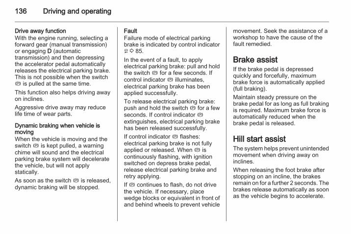
136 Driving and operating
Drive away functionWith the engine running, selecting aforward gear (manual transmission)or engaging D (automatictransmission) and then depressingthe accelerator pedal automaticallyreleases the electrical parking brake.This is not possible when the switchm is pulled at the same time.This function also helps driving awayon inclines.Aggressive drive away may reducelife time of wear parts.
Dynamic braking when vehicle ismovingWhen the vehicle is moving and theswitch m is kept pulled, a warningchime will sound and the electricalparking brake system will deceleratethe vehicle, but will not applystatically.As soon as the switch m is released,dynamic braking will be stopped.
FaultFailure mode of electrical parkingbrake is indicated by control indicatorj 3 85.In the event of a fault, to applyelectrical parking brake: pull and holdthe switch m for a few seconds. Ifcontrol indicator m illuminates,electrical parking brake has beenapplied successfully.To release electrical parking brake:push and hold the switch m for a fewseconds. If control indicator mextinguishes, electrical parking brakehas been released successfully.If control indicator m flashes:electrical parking brake is not fullyapplied or released. When m iscontinuously flashing, with ignitionswitched on depress brake pedal,release electrical parking brake andretry applying.If m continues to flash, do not drivethe vehicle. If necessary, placewedge blocks or equivalent in front ofand behind wheels to prevent vehicle
movement. Seek the assistance of aworkshop to have the cause of thefault remedied.
Brake assistIf the brake pedal is depressedquickly and forcefully, maximumbrake force is automatically applied(full braking).Maintain steady pressure on thebrake pedal for as long as full brakingis required. Maximum brake force isautomatically reduced when thebrake pedal is released.
Hill start assistThe system helps prevent unintendedmovement when driving away oninclines.When releasing the foot brake afterstopping on an incline, the brakesremain on for a further 2 seconds. Thebrakes release automatically as soonas the vehicle begins to accelerate.

Driving and operating 137
Ride control systemsElectronic Stability ControlElectronic Stability Control (ESC)improves driving stability whennecessary, regardless of the type ofroad surface or tyre grip. It alsoprevents the drive wheels fromspinning.As soon as the vehicle starts toswerve (understeer/oversteer),engine output is reduced and thewheels are braked individually. Thisconsiderably improves the drivingstability of the vehicle on slippery roadsurfaces.ESC is operational as soon as controlindicators b and t extinguish in theinstrument cluster after switching onthe ignition.When ESC is active b flashes 3 86.
9 Warning
Do not let this special safetyfeature tempt you into taking riskswhen driving.Adapt speed to the roadconditions.
Deactivation
With ESC active, if wheels areslipping on wet, snowy or icy roads,engine speed may not increase whenaccelerator pedal is depressed. Thevehicle may not move.
Switch off ESC function, to allowengine rpm to increase, by pressingbutton t briefly. Control indicator tilluminates in the instrument cluster.ESC is reactivated by pressing buttont again. The control indicatorextinguishes.Control indicator t 3 87.
Hydraulic brake assistWhen the ESC function comes intoaction and recognises anyemergency situation requiring hardbraking, it automatically deliversincreased braking pressure to thewheels.
Active rollover protectionIf the vehicle moves in an unstablemanner, this function helps thevehicle maintain normal stability.

138 Driving and operating
Trailer stability assistIf the system detects snakingmovements, engine power is reducedand the vehicle/trailer combination isselectively braked until the snakingceases. While system is working keepsteering wheel as still as possible.
Descent control systemThe Descent control system (DCS)allows the vehicle to travel at a lowspeed without depressing the footbrake. The vehicle will automaticallydecelerate to a low speed and remainat that speed when the system isactivated. Some noise or vibrationfrom the brake system may beapparent when the system is active.
Caution
Use only when descending steepgrades while driving off-road. Donot use when driving on normalroad surfaces. Unnecessaryusage of the DCS function, such
as while driving on normal roads,may damage the brake systemand the ESC function.
Activation
At speeds below approx. 30 mph,press button u. The green controlindicator u flashes in the instrumentcluster, to show DCS is in operation.DCS will not activate at speeds above30 mph, even if the button is pressed.
DeactivationPress button u again. The greencontrol indicator u extinguishes.Depressing the foot brake oraccelerator will also cause the systemto be deactivated.
FaultThe yellow control indicator u flashesto indicate that the system is notready for conditions to operate, due tothe high temperature (approx.350 - 400 °C) of friction material,through severe or repeated braking. Itwill extinguish when the temperaturedrops below 350 °C.The yellow control indicator uilluminates when there is amalfunction in the system, due to theextremely high temperature(over 400 °C) of friction material,through severe or repeated braking. Itwill extinguish when the temperaturedrops below 350 °C. Thesetemperatures may differ according tovehicle conditions or outsideconditions.
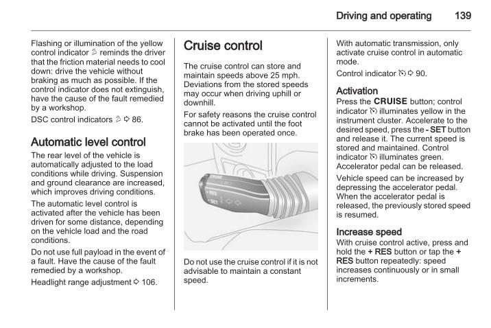
Driving and operating 139
Flashing or illumination of the yellowcontrol indicator u reminds the driverthat the friction material needs to cooldown: drive the vehicle withoutbraking as much as possible. If thecontrol indicator does not extinguish,have the cause of the fault remediedby a workshop.DSC control indicators u 3 86.
Automatic level controlThe rear level of the vehicle isautomatically adjusted to the loadconditions while driving. Suspensionand ground clearance are increased,which improves driving conditions.The automatic level control isactivated after the vehicle has beendriven for some distance, dependingon the vehicle load and the roadconditions.Do not use full payload in the event ofa fault. Have the cause of the faultremedied by a workshop.Headlight range adjustment 3 106.
Cruise controlThe cruise control can store andmaintain speeds above 25 mph.Deviations from the stored speedsmay occur when driving uphill ordownhill.For safety reasons the cruise controlcannot be activated until the footbrake has been operated once.
Do not use the cruise control if it is notadvisable to maintain a constantspeed.
With automatic transmission, onlyactivate cruise control in automaticmode.Control indicator m 3 90.
ActivationPress the e button; controlindicator m illuminates yellow in theinstrument cluster. Accelerate to thedesired speed, press the - SET buttonand release it. The current speed isstored and maintained. Controlindicator m illuminates green.Accelerator pedal can be released.Vehicle speed can be increased bydepressing the accelerator pedal.When the accelerator pedal isreleased, the previously stored speedis resumed.
Increase speedWith cruise control active, press andhold the + RES button or tap the +RES button repeatedly: speedincreases continuously or in smallincrements.
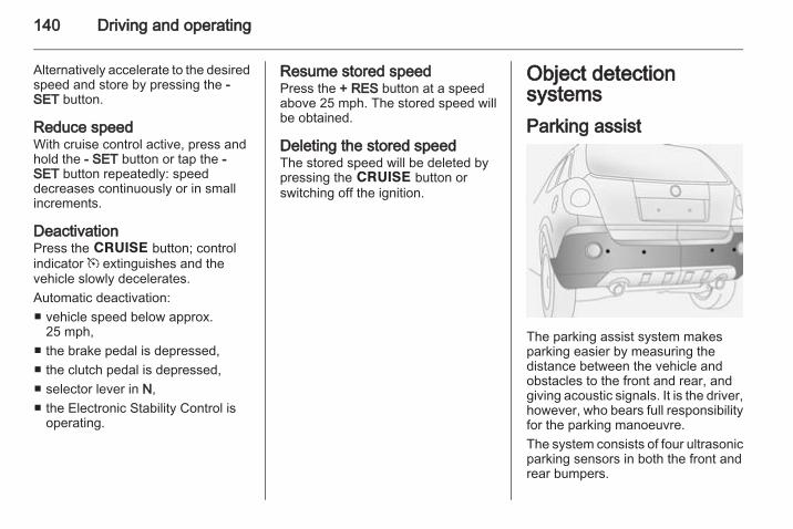
140 Driving and operating
Alternatively accelerate to the desiredspeed and store by pressing the -SET button.
Reduce speedWith cruise control active, press andhold the - SET button or tap the -SET button repeatedly: speeddecreases continuously or in smallincrements.
DeactivationPress the e button; controlindicator m extinguishes and thevehicle slowly decelerates.Automatic deactivation:■ vehicle speed below approx.
25 mph,■ the brake pedal is depressed,■ the clutch pedal is depressed,■ selector lever in N,■ the Electronic Stability Control is
operating.
Resume stored speedPress the + RES button at a speedabove 25 mph. The stored speed willbe obtained.
Deleting the stored speedThe stored speed will be deleted bypressing the e button orswitching off the ignition.
Object detectionsystemsParking assist
The parking assist system makesparking easier by measuring thedistance between the vehicle andobstacles to the front and rear, andgiving acoustic signals. It is the driver,however, who bears full responsibilityfor the parking manoeuvre.The system consists of four ultrasonicparking sensors in both the front andrear bumpers.

Driving and operating 141
Control indicator r 3 86.
Activation
With the ignition on, the system mustbe activated manually.Press button r on the instrumentpanel. The LED in the button willilluminate and will activate when aforward gear or reverse gear isengaged and the electrical parkingbrake is released.An obstacle is indicated by anacoustic signal. The interval betweenthe sounds becomes shorter as thevehicle gets closer to the obstacle.
When the distance is less than30 cm, the signal is continuous. Theacoustic signal may differ dependingon the type of object detected.
DeactivationTo deactivate, press the button againand the LED in the button willextinguish. The control indicator rin the instrument cluster will illuminateuntil the vehicle speed exceeds18 mph.The system is deactivatedautomatically when the vehicle speedis above 5 mph or when selector leveris in neutral (automatic transmissionin N or P).If the b button is pressed again, theLED in the button will extinguish andthe system will be reactivated as soonas a forward gear or reverse gear isengaged and the electrical parkingbrake is released.
FaultIn the event of a fault in the system,control indicator r illuminates in theinstrument cluster.
If the acoustic signal sounds 3 timescontinuously when there are noobstacles near the front or rearbumper, there is a fault in the system.Have the cause of the fault remediedby a workshop.
Important hints for using theparking assist system
9 Warning
Under certain circumstances,various reflective surfaces onobjects or clothing as well asexternal noise sources may causethe system to fail to detectobstacles.
Caution
Performance of the system can bereduced when sensors arecovered, e.g. by ice or snow.Performance of the parking assistsystem can be reduced due toheavy loading.

142 Driving and operating
Special conditions apply if thereare taller vehicles in the vicinity(e.g. off-road vehicles, mini vans,vans). Object identification andcorrect distance indication in theupper part of these vehiclescannot be guaranteed.Objects with a very small reflectioncross-section, e.g. objects ofnarrow size or soft materials, maynot be detected by the system.Parking assist systems do notdetect objects outside thedetection range.
FuelFuel for petrol enginesOnly use unleaded fuel that complieswith European standard EN 228 orE DIN 51626-1 or equivalent.Your engine is capable of runningwith E10 fuel that fulfills thesestandards. E10 fuel contains up to10 % bioethanol.Use fuel with the recommendedoctane rating 3 199. Use of fuel withtoo low an octane rating can reduceengine power and torque and slightlyincreases fuel consumption.
Caution
Do not use fuel or fuel additivesthat contain metallic compoundssuch as manganese-basedadditives. This may cause enginedamage.
Caution
Use of fuel that does not comply toEN 228 or E DIN 51626-1 orequivalent can lead to deposits orengine damage and may affectyour warranty.
Caution
Use of fuel with too low an octanerating could lead to uncontrolledcombustion and engine damage.
NoteUse unleaded Premium fuel only forthe following countries:Armenia, Azerbaijan, Belarus,Moldova.
Fuel for ethanol adaptedengines (E85)If access to E85 is limited then fuelwith a different proportion of ethanolor normal RON 95 can be used forrefuelling. The engine's control

Driving and operating 143
management system is adjustedautomatically according to theamount of ethanol in the fuel.E85 fuel must fulfil the CWA 15293 orSS 155480 standard.When the temperature is about-10 °C or lower a greater proportion ofpetrol should be used. E85 incombination with low temperaturescould lead to the car being moredifficult to start. A slightly higherproportion of petrol improves the coldstart properties considerably.During the engine's warm-up phase(below +50 °C) engine torque islimited when driving with a proportionof ethanol.Ethanol contains less energy per litrethan petrol, which is why fuelconsumption increases when drivingon E85 compared with petrol. Aconsequence of this is that a tank ofE85 covers fewer miles than a tank ofpetrol.
Caution
Certain additives in petrol could, incombination with ethanol, causereduced driveability. For thisreason, refuel with a full tank ofpetrol every 6000 miles. Use upthe majority of this beforerefuelling the car again.
Fuel for diesel enginesOnly use diesel fuel that complieswith EN 590.In countries outside the EuropeanUnion use Euro-Diesel fuel with asulphur concentration below 50 ppm.
Caution
Use of fuel that does not complywith EN 590 or similar can lead toengine power loss, increasedwear or engine damage and lossof warranty.
Do not use marine diesel oils, heatingoils, Aquazole and similar diesel-water emulsions. Diesel fuels mustnot be diluted with fuels for petrolengines.
Refuelling
9 Danger
Before refuelling, switch off engineand any external heaters withcombustion chambers. Switch offany mobile phones.Follow the operating and safetyinstructions of the filling stationwhen refuelling.
9 Danger
Fuel is flammable and explosive.No smoking. No naked flames orsparks.If you can smell fuel in yourvehicle, have the cause of thisremedied immediately by anauthorized dealer.

144 Driving and operating
Caution
In case of misfuelling, do notswitch on ignition.
Fuel filler flap is located at left rearside of vehicle.The fuel filler flap can only be openedif the vehicle is unlocked 3 20.Release the fuel filler flap by pushingthe flap.
To unlock fuel filler cap: turn itanticlockwise. If hissing occurs, waituntil it stops before completelyunscrewing the cap.
The fuel filler cap can be retained inthe holder on the inside of the fuelfiller flap.After refuelling, replace the fuel fillercap and turn it clockwise until youhear several clicks. Ensure the cap isscrewed in completely, otherwisecontrol indicator Z may illuminate inthe instrument cluster 3 84.Close fuel filler flap.
Caution
Wipe off any overflowing fuelimmediately.
Fuel filler capOnly a genuine fuel filler cap providesfull functionality. Diesel-enginedvehicles have special fuel filler caps.
Fuel consumption - CO2-EmissionsThe fuel consumption (combined) ofthe model Vauxhall Antara is within arange of 25 to 45 mpg.
The CO2 emission (combined) iswithin a range of 167 to 255 g/km.For the values specific for yourvehicle, refer to the EEC Certificate ofConformity provided with your vehicleor other national registrationdocuments.
General informationThe official fuel consumption andspecific CO2 emission figures quotedrelate to the EU base model withstandard equipment.Fuel consumption data and CO2emission data are determinedaccording to regulation R (EC) No.715/2007 (in the version respectivelyapplicable), taking into considerationthe vehicle weight in running order, asspecified by the regulation.The figures are provided only for thepurpose of comparison betweendifferent vehicle variants and mustnot be taken as a guarantee for theactual fuel consumption of aparticular vehicle. Additionalequipment may result in slightlyhigher results than the stated

Driving and operating 145
consumption and CO2 figures.Furthermore, fuel consumption isdependent on personal driving styleas well as road and traffic conditions.
TowingGeneral informationThe coupling ball bar is kept in a bag,fastened with a strap and is stowedbelow the floor cover in the loadcompartment.Entrust retrofitting of towingequipment to a workshop. It may benecessary to make changes thataffect the cooling system, heatshields or other equipment. Only usetowing equipment that has beenapproved for your vehicle.Control indicator á illuminates in theinstrument cluster when a trailer isconnected to the vehicle 3 90.
Driving characteristics andtowing tipsIn the case of trailers with brakes,attach the break-away stopping cableto the eye - not to the coupling ballbar.
If no eye is available, loop cablearound coupling ball bar. Ensurecable is crossed under the verticalcoupling socket to ensure the trailernose cannot drop to the ground if itbecomes separated from the trailerhitch. Do not allow the cable to dragalong the ground and always allowenough slack to permit full turning.Follow the instructions supplied withthe towing equipment.Before attaching a trailer, lubricatethe coupling ball. However, do not doso if a stabiliser, which acts on thecoupling ball, is being used to reducesnaking movements. For trailers withlow driving stability, the use of afriction-type stabiliser is stronglyrecommended.Do not drive faster than 50 mph, evenin countries where higher speeds arepermitted. When driving uphill, do notdrive faster than 20 mph in 1st gear,or 30 mph in 2nd gear.If the trailer starts snaking, drive moreslowly, do not attempt to correct thesteering and brake sharply ifnecessary.

146 Driving and operating
When driving downhill, drive in thesame gear as if driving uphill anddrive at a similar speed.Adjust tyre pressure to the valuespecified for full load 3 205.
Trailer towingTrailer loadsThe permissible trailer loads arevehicle-dependent and engine-dependent maximum values whichmust not be exceeded. The actualtrailer load is the difference betweenthe actual gross weight of the trailerand the actual coupling socket loadwith the trailer coupled.When the trailer load is beingchecked, therefore, only the trailerwheels - and not the jockey wheel -must be standing on the weighingapparatus.The permissible trailer loads arespecified in the vehicle documents. Ingeneral, they are valid for gradientsup to max. 12 %.
The permitted trailer load applies upto the specified incline and up to analtitude of 1000 metres above sealevel. Since engine power decreasesas altitude increases due to the airbecoming thinner, therefore reducingclimbing ability, the permissible grosstrain weight also decreases by 10 %for every 1000 metres of additionalaltitude. The gross train weight doesnot have to be reduced when drivingon roads with slight inclines (less than8 %, e.g. motorways).The permissible gross train weightmust not be exceeded. This weight isspecified on the identification plate3 195.
Vertical coupling loadThe vertical coupling load is the loadexerted by the trailer on the couplingball. It can be varied by changing theweight distribution when loading thetrailer.The maximum permissible verticalcoupling load (80 kg) is specified onthe towing equipment identificationplate and in the vehicle documents.Always aim for the maximum load,
especially in the case of heavytrailers. The vertical coupling loadshould never fall below 25 kg.When measuring the vertical couplingload, ensure the drawbar of theloaded trailer is at the same height asit will be when the trailer is coupledwith the towing vehicle loaded. This isparticularly important for trailers withtandem axle.
Rear axle loadWhen the trailer is coupled and thetowing vehicle is fully loaded(including all occupants), thepermissible rear axle load (seeidentification plate or vehicledocuments) must not be exceeded.National regulations regardingmaximum speeds for vehicles towinga trailer must be observed.
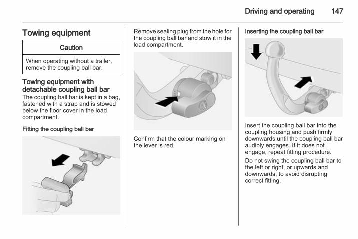
Driving and operating 147
Towing equipment
Caution
When operating without a trailer,remove the coupling ball bar.
Towing equipment withdetachable coupling ball barThe coupling ball bar is kept in a bag,fastened with a strap and is stowedbelow the floor cover in the loadcompartment.
Fitting the coupling ball bar
Remove sealing plug from the hole forthe coupling ball bar and stow it in theload compartment.
Confirm that the colour marking onthe lever is red.
Inserting the coupling ball bar
Insert the coupling ball bar into thecoupling housing and push firmlydownwards until the coupling ball baraudibly engages. If it does notengage, repeat fitting procedure.Do not swing the coupling ball bar tothe left or right, or upwards anddownwards, to avoid disruptingcorrect fitting.

148 Driving and operating
Lock coupling ball bar by turning thesupplied key in the lock cylinder of thecoupling ball bar. Remove key.Check that the coupling ball bar iscorrectly attached:■ Green marking must be visible on
lever.■ Coupling ball bar must be seated
firmly in coupling housing.Coupling ball bar must be locked andkey must be removed.
9 Warning
Towing a trailer is permitted onlywhen the coupling ball bar is fittedcorrectly. If the coupling ball barcannot be properly attached, seekthe assistance of a workshop.
Eye for break-away stopping cableIn the case of trailers with brakes,attach the break-away stopping cableto the eye - not to the coupling ballbar.
Dismounting the coupling ball bar
Unlock coupling ball bar and removekey. Push lever to the left, towards thecoupling ball bar and turn itdownwards. Pull coupling ball bar outof coupling housing.Remove any rust or dirt from areaaround the coupling housing andcoupling ball bar connection beforeinserting sealing plug in the hole.Place the coupling ball bar in the bagsupplied, fasten it with the strap andstow it below the floor cover in theload compartment.Do not use steam-jet cleaners orother high-pressure cleaners to cleanthe coupling ball bar.
Trailer stability assistIf the system detects snakingmovements, engine power is reducedand the vehicle/trailer combination isselectively braked until the snakingceases. While system is working keepsteering wheel as still as possible.Trailer stability assist (TSA) is afunction of the Electronic StabilityControl 3 137.

Vehicle care 149
Vehicle care
General Information ................... 149Vehicle checks ........................... 150Bulb replacement ....................... 158Electrical system ........................ 164Vehicle tools .............................. 171Wheels and tyres ....................... 173Jump starting ............................. 184Towing ....................................... 186Appearance care ....................... 188
General InformationAccessories and vehiclemodificationsWe recommend the use of genuineparts and accessories and factoryapproved parts specific for yourvehicle type. We cannot assess orguarantee reliability of other products- even if they have a regulatory orotherwise granted approval.Do not make any modifications to theelectrical system, e.g. changes ofelectronic control units (chip tuning).
Caution
When transporting the vehicle ona train or on a recovery vehicle, themud flaps might be damaged.
Vehicle storageStorage for a long period of timeIf the vehicle is to be stored for severalmonths:■ Wash and wax the vehicle.■ Have the wax in the engine
compartment and underbodychecked.
■ Clean and preserve the rubberseals.
■ Change the engine oil.■ Drain the washer fluid reservoir.■ Check the coolant antifreeze and
corrosion protection.■ Adjust tyre pressure to the value
specified for full load.■ Park the vehicle in a dry, well
ventilated place. Engage first orreverse gear or move selector leverto P. Prevent the vehicle fromrolling.
■ Do not apply the electrical parkingbrake.

150 Vehicle care
■ Open the bonnet, close all doorsand lock the vehicle.
■ Disconnect the clamp from thenegative terminal of the vehiclebattery. Beware that all systems arenot functional, e.g. anti-theft alarmsystem.
Putting back into operationWhen the vehicle is to be put back intooperation:■ Connect the clamp to the negative
terminal of the vehicle battery.Activate the electronics of thepower windows.
■ Check tyre pressure.■ Fill up the washer fluid reservoir.■ Check the engine oil level.■ Check the coolant level.■ Fit the number plate if necessary.Seek the assistance of a workshop forfurther advice.
End-of-life vehiclerecoveryInformation on end-of-life vehiclerecovery centres and the recycling ofend-of-life vehicles is available on ourwebsite, where legally required. Onlyentrust this work to an authorisedrecycling centre.
Vehicle checksPerforming work
9 Warning
Only perform engine compartmentchecks when the ignition is off.The cooling fan may startoperating even if the ignition is off.
9 Danger
The ignition system and Xenonheadlights use extremely highvoltage. Do not touch.

Vehicle care 151
BonnetOpening
Pull the release lever and return it toits original position.
Locate the safety catch, found slightlyleft of centre on the underside of thebonnet, push the catch upwards andlift the bonnet gently.The bonnet is held openautomatically.If the bonnet is opened during anAutostop, the engine will be restartedautomatically for safety reasons.Air intake 3 120.
ClosingLower the bonnet and allow it to dropinto the catch. Check that the bonnetis engaged.
Engine oilCheck the engine oil level manuallyon a regular basis to prevent damageto the engine.Ensure that the correct specificationof oil is used. Recommended fluidsand lubricants 3 192.Check with the vehicle on a levelsurface. The engine must be atoperating temperature and switchedoff for at least 5 minutes.Pull out the dipstick, wipe it clean,insert it to the stop on the handle, pullout and read the engine oil level.
Caution
It is the owner's responsibility tomaintain the proper level of anappropriate quality oil in theengine.
Insert dipstick to the stop on thehandle and make half a turn.

152 Vehicle care
Different dipsticks are useddepending on engine variant.When the engine oil level hasdropped to the MIN mark, top upengine oil.
We recommend the use of the samegrade of engine oil that was used atthe last oil change.The engine oil level must not exceedthe MAX mark on the dipstick.
Caution
Overfilled engine oil must bedrained or suctioned out.
Capacities 3 204, Engine oil quality/viscosity 3 192.Fit the cap on straight and tighten it.
Control indicators for engine oilpressure I 3 87, low engine oil S3 88 and engine oil life C 3 88.Once the engine oil has beenchanged, the engine oil life monitorneeds to be reset. Seek theassistance of a workshop.
Engine coolantThe coolant provides freezeprotection down to approx. -28 °C.
Caution
Only use approved antifreeze.
Coolant level
Caution
Too low a coolant level can causeengine damage.

Vehicle care 153
If the cooling system is cold, thecoolant level should be between theMIN and MAX marks. Top up if thelevel is low.
9 Warning
Allow the engine to cool beforeopening the cap. Carefully openthe cap, relieving the pressureslowly.
To top up use a 1:1 mixture ofreleased coolant concentrate mixedwith clean tap water. If no coolantconcentrate is available, use cleantap water. Install the cap tightly. Have
the coolant concentration checkedand have the cause of the coolantloss remedied by a workshop.Engine coolant temperature controlindicator W 3 87.
Power steering fluid
Open the cap and remove. Wipe thedipstick dry and turn the cap in thecontainer. Open the cap again andread the power steering fluid level.The power steering fluid level must bebetween the MIN/COLD and theMAX/HOT marks.
If the fluid level is too low, seek theassistance of a workshop.
Washer fluid
Fill with clean water mixed with asuitable quantity of washer fluid whichcontains antifreeze. For the correctmixing ratio refer to the washer fluidcontainer.

154 Vehicle care
Caution
Only washer fluid with a sufficientantifreeze concentration providesprotection at low temperatures ora sudden drop in temperature.
Do not spray washer fluid ontowindscreen in freezing weather, toavoid ice forming and impairingvision.In cold weather, do not fill the washerfluid reservoir more than threequarters full, to allow enough room forexpansion if the fluid freezes, and toprevent damage to the reservoir.
BrakesA squealing noise indicates that thebrake lining is at its minimumthickness. Continued driving ispossible but have the brake liningreplaced as soon as possible.Once new brake linings are installed,do not brake unnecessarily hard forthe first few journeys.
Brake fluid
9 Warning
Brake fluid is poisonous andcorrosive. Avoid contact with eyes,skin, fabrics and painted surfaces.
The brake fluid level must be betweenthe MIN and MAX marks.When topping up, ensure maximumcleanliness as contamination of thebrake fluid can lead to brake systemmalfunctions. Have the cause of theloss of brake fluid remedied by aworkshop.
Caution
Only use high-performance brakefluid approved for the vehicle.Brake fluid 3 192.
Brake fluid level control indicator R3 84.
Clutch fluid
9 Warning
Clutch fluid is poisonous andcorrosive. Avoid contact with eyes,skin, fabrics and painted surfaces.

Vehicle care 155
If the fluid in the reservoir falls belowthe MIN mark, seek the assistance ofa workshop.Clutch fluid 3 192.
BatteryVehicles without stop-start systemwill be equipped with a lead acidbattery. Vehicles with stop-startsystem will be equipped with an AGMbattery which is not a lead acidbattery.The vehicle battery is maintenance-free provided that the driving profileallows sufficient charging of the
battery. Short-distance-driving andfrequent engine starts can dischargethe battery. Avoid the use ofunnecessary electrical consumers.
Batteries do not belong in householdwaste. They must be disposed of atan appropriate recycling collectionpoint.Laying up the vehicle for more than6 weeks can lead to batterydischarge. Disconnect the clamp fromthe negative terminal of the vehiclebattery. Ensure the ignition isswitched off before connecting ordisconnecting the vehicle battery.Retrofitted electrical or electronicaccessories can place an additionalload on the battery or discharge thebattery. Seek the assistance of aworkshop regarding technicalpossibilities, such as fitting a morepowerful battery.
Ensure the ignition is switched offbefore reconnecting the battery. Thenperform the following actions:1. Set date and time in the
information display 3 76.2. If necessary, activate the power
windows and sun roof 3 29, 3 31.In order to prevent the battery fromdischarging, some consumers suchas the courtesy lights automaticallyswitch off after a delay.Charge a disconnected battery every6 weeks.Battery discharge protection 3 113.
Replacing the batteryNoteAny deviation from the instructionsgiven in this paragraph may lead toa temporary deactivation of the stop-start system.
When the battery is being replaced,please ensure that there are no openventilation holes in the vicinity of thepositive terminal. If a ventilation holeis open in this area, it must be closed

156 Vehicle care
off with a dummy cap, and theventilation in the vicinity of thenegative terminal must be opened.Only use batteries that allow the fusebox to be mounted above the battery.In vehicles with stop-start system,ensure to have the AGM (AbsorptiveGlass Mat) battery replaced with anAGM battery again.
An AGM battery can be identified bythe label on the battery. Werecommend the use of an originalVauxhall battery.
NoteUsing an AGM battery different fromthe original Vauxhall battery mightresult in a lower performance of thestop-start system.
We recommend that you have thebattery replaced by a workshop.Stop-start system 3 123.
Charging the battery
9 Warning
On vehicles with stop-startsystem, ensure that the chargingpotential does not exceed 14.6volts when using a batterycharger. Otherwise the batterymight be damaged.
Jump starting 3 184.
Warning label
Meaning of symbols:■ No sparks, naked flames or
smoking.■ Always shield eyes. Explosive
gases can cause blindness orinjury.
■ Keep the battery out of reach ofchildren.
■ The battery contains sulfuric acidwhich could cause blindness orserious burn injuries.
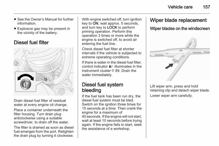
Vehicle care 157
■ See the Owner’s Manual for furtherinformation.
■ Explosive gas may be present inthe vicinity of the battery.
Diesel fuel filter
Drain diesel fuel filter of residualwater at every engine oil change.Place a container underneath thefilter housing. Turn drain pluganticlockwise using a suitablescrewdriver, to drain off the water.The filter is drained as soon as dieselfuel emerges from the port. Retightenthe drain plug by turning it clockwise.
With engine switched off, turn ignitionkey to ON, wait approx. 5 seconds,and turn key to LOCK to performpriming operation. Perform thisoperation 3 times or more while theengine is switched off, to avoid airentering the fuel line.Check diesel fuel filter at shorterintervals if the vehicle is subjected toextreme operating conditions.If there is water in the diesel fuel filter,control indicator U illuminates in theinstrument cluster 3 89. Drain thewater immediately.
Diesel fuel systembleedingIf the fuel tank has been run dry, thediesel fuel system must be bled.Switch on the ignition three times for15 seconds at a time. Then crank theengine for a maximum of40 seconds. If the engine will not start,wait at least 10 seconds before tryingagain. If the engine fails to start, seekthe assistance of a workshop.
Wiper blade replacementWiper blades on the windscreen
Lift wiper arm, press and holdretaining clip and detach wiper blade.Lower wiper arm carefully.

158 Vehicle care
Bulb replacementSwitch off the ignition and turn off therelevant switch or close the doors.Only hold a new bulb at the base! Donot touch the bulb glass with barehands.Use only the same bulb type forreplacement.Replace headlight bulbs from withinthe engine compartment.
Bulb checkAfter a bulb replacement switch onthe ignition, operate and check thelights.
HeadlightsHeadlamp removalFor bulb replacement, it is necessaryto first remove the headlampassembly.
1. Switch off the ignition andheadlight switch.
2. Open the bonnet, release the11 retainers and remove theradiator cover.
3. Remove 3 bolts and withdrawheadlamp.
4. Depress harness connector tagsand disconnect headlamp wiring.
5. Remove the headlamp assembly.Headlamp assembly installation is thereverse of removal - ensure locatingdowel aligns with its socket. Do notovertighten bolts or retainers.
Halogen headlights
Halogen headlights A can beidentified from Xenon headlights B bythe different lens layout.

Vehicle care 159
Low and high beam
Halogen headlights have separatesystems for high beam 1 (inner bulbs)and low beam 2 (outer bulbs).1. Remove headlamp assembly
3 158.2. Remove headlamp cap.3. Release bulb retaining spring and
remove bulb from reflectorhousing.
4. When inserting a new bulb,ensure the lugs engage correctlywith the recesses on the reflector.
5. Engage bulb retaining spring andreplace headlamp cap.
6. Reinstall headlamp assembly.
Front turn signal
1. Remove headlamp assembly3 158.
2. Rotate bulb holder anticlockwiseand withdraw bulb holder fromlamp assembly.
3. Press and rotate bulbanticlockwise to remove it frombulb holder.
4. Insert new bulb into bulb holder bypressing and rotating it clockwise.
5. Reinstall bulb holder in lampassembly by rotating it clockwise.
6. Reinstall headlamp assembly.
Sidelights
1. Remove headlamp assembly3 158.
2. Remove headlamp cap andwithdraw bulb holder (locatednext to high beam bulb) from lampassembly.
3. Remove bulb from bulb holder bypulling it straight out.
4. Insert new bulb, using a lint-freecloth to hold bulb.

160 Vehicle care
5. Reinstall bulb holder in lampassembly and replace headlampcap.
6. Reinstall headlamp assembly.
Xenon headlights
Xenon headlights B can be identifiedfrom Halogen headlights A by thedifferent lens layout.
Low and high beam
9 Danger
Xenon headlights work underextremely high electrical voltage.Do not touch. Have bulbs replacedby a workshop.
Front turn signal
1. Remove headlamp assembly3 158.
2. Rotate bulb holder anticlockwiseand withdraw bulb holder fromlamp assembly.
3. Press and rotate bulbanticlockwise to remove it frombulb holder.
4. Insert new bulb into bulb holder bypressing and rotating it clockwise.
5. Reinstall bulb holder in lampassembly by rotating it clockwise.
6. Reinstall headlamp assembly.
Sidelights
1. Remove headlamp assembly3 158.
2. Rotate bulb holder anticlockwiseand withdraw bulb holder fromlamp assembly.

Vehicle care 161
3. Remove bulb from bulb holder bypulling it straight out.
4. Insert new bulb, using a lint-freecloth to hold bulb.
5. Reinstall bulb holder in lampassembly by rotating it clockwise.
6. Reinstall headlamp assembly.
Fog lights
1. Remove 2 screws from panel onunderside of vehicle below frontfog lights and remove panel.
2. Disconnect harness connectorfrom bulb holder and rotate bulbholder anticlockwise.
3. Remove bulb holder from lampassembly, rotate bulbanticlockwise and remove frombulb holder.
4. Insert new bulb into bulb holderand rotate it clockwise.
5. Reinstall bulb holder in lampassembly and reconnect harnessconnector.
6. Reinstall panel to underside ofvehicle using 2 screws removedearlier.
Tail lightsRear brake, tail, turn signal,reverse and fog tail light
1. Open the tailgate and remove2 screws and lamp assembly.
2. Remove bulb holder by rotating itanticlockwise.
3. Remove bulb from bulb holder bypressing the bulb in and rotating itanticlockwise.
4. Insert new bulb into bulb holder.5. Reinstall bulb holder into lamp
assembly. Rotate bulb holderclockwise and ensure it is secure.

162 Vehicle care
6. Replace lamp assembly byguiding lugs on lamp assemblyinto their correspondingapertures.
7. Replace 2 screws removed earlierand close the tailgate.
Side turn signal lights
1. Using a suitable screwdriver, prylamp assembly away from wing.
2. Rotate bulb holder anticlockwise.3. Remove bulb from lamp assembly
by pulling bulb straight out of bulbholder.
4. Insert new bulb into bulb holder bypressing it in and rotating the bulbholder clockwise.
5. Push lamp assembly back intoaperture.
Centre high-mountedbrake lightHave bulbs replaced by a workshop.
Number plate light
1. Remove 4 screws (arrowed) andremove lamp covers.
2. Remove bulb holder from lampassembly by rotating itanticlockwise.
3. Pull bulb straight out of bulbholder.
4. Insert new bulb.

Vehicle care 163
5. Reinstall bulb holder into lampassembly, rotate bulb holderclockwise and ensure it is secure.
6. Replace lamp covers using the4 screws removed earlier.
Interior lightsFront reading lights
1. Using a suitable screwdriver, prylamp lens away from roof lining.
2. Remove bulb.3. Insert new bulb.4. Reinstall lamp lens in roof lining.
Rear reading lights
1. Using a suitable screwdriver, prylamp lens away from roof lining.
2. Remove bulb.3. Insert new bulb.4. Reinstall lamp lens in roof lining.
Load compartment light
1. Using a suitable screwdriver,remove lens from lamp assembly.
2. Remove bulb.3. Insert new bulb.4. Reinstall lens to lamp assembly.
Glovebox lightHave bulbs replaced by a workshop.
Instrument panelilluminationHave bulbs replaced by a workshop.

164 Vehicle care
Electrical systemFusesData on the replacement fuse mustmatch the data on the defective fuse.There are two fuse boxes in thevehicle:■ in the engine compartment next to
the coolant reservoir,■ in the instrument panel, on the left-
hand side of the front passengerseat foot well, or, in right-hand drivevehicles, on the left-hand side ofthe driver's seat foot well.
Before replacing a fuse, turn off therespective switch and the ignition.A blown fuse can be recognized by itsmelted wire. Do not replace the fuseuntil the cause of the fault has beenremedied.Some functions are protected byseveral fuses. Fuses may also beinserted without existence of afunction.
It is advisable to carry a full set ofspare fuses. Spare fuses can bestored in the engine compartmentfuse box.
Fuse extractorA fuse extractor may be located in theengine compartment fuse box.

Vehicle care 165
Place the fuse extractor on thevarious types of fuse from the top orside, and withdraw fuse.
Engine compartment fusebox
The fuse box is located next to thecoolant reservoir in the enginecompartment.To open, disengage cover and tiltupwards.

166 Vehicle care
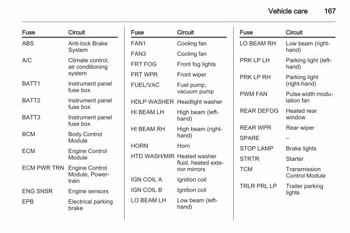
Vehicle care 167
Fuse Circuit
ABS Anti-lock BrakeSystem
A/C Climate control,air conditioningsystem
BATT1 Instrument panelfuse box
BATT2 Instrument panelfuse box
BATT3 Instrument panelfuse box
BCM Body ControlModule
ECM Engine ControlModule
ECM PWR TRN Engine ControlModule, Power‐train
ENG SNSR Engine sensors
EPB Electrical parkingbrake
Fuse Circuit
FAN1 Cooling fan
FAN3 Cooling fan
FRT FOG Front fog lights
FRT WPR Front wiper
FUEL/VAC Fuel pump,vacuum pump
HDLP WASHER Headlight washer
HI BEAM LH High beam (left-hand)
HI BEAM RH High beam (right-hand)
HORN Horn
HTD WASH/MIR Heated washerfluid, heated exte‐rior mirrors
IGN COIL A Ignition coil
IGN COIL B Ignition coil
LO BEAM LH Low beam (left-hand)
Fuse Circuit
LO BEAM RH Low beam (right-hand)
PRK LP LH Parking light (left-hand)
PRK LP RH Parking light(right-hand)
PWM FAN Pulse width modu‐lation fan
REAR DEFOG Heated rearwindow
REAR WPR Rear wiper
SPARE –
STOP LAMP Brake lights
STRTR Starter
TCM TransmissionControl Module
TRLR PRL LP Trailer parkinglights

168 Vehicle care
After changing of defective fusesclose the fuse box cover and pressuntil it engages.If the fuse box cover is not closedcorrectly, malfunctions may occur.
Instrument panel fuse box
The fuse box is located on the left-hand side of the front passenger seatfoot well, or, in right-hand drivevehicles, on the left-hand side of thedriver's seat foot well.Release latch to open cover.

Vehicle care 169

170 Vehicle care
Fuse Circuit
AMP Amplifier
APO JACK(CONSOLE)
Power outlet(centre console)
APO JACK(REAR CARGO)
Power outlet(load compart‐ment)
AWD/VENT All-wheel drive,ventilation
BCM (CTSY) Courtesy lights
BCM (DIMMER) Instrument illu‐mination
BCM (INT LIGHTTRLR FOG)
Interior lights,trailer fog light
BCM (PRK/TRN) Parking lights,turn signals
BCM (STOP) Brake lights
BCM (TRN SIG) Turn signals
BCM (VBATT) Battery voltage
CIGAR Cigarette lighter
Fuse Circuit
CIM Communica‐tions IntegrationModule
CLSTR Instrumentcluster
DRL Daytime runninglights
DR/LCK Driver door lock
DRVR PWRSEAT
Driver powerseat
DRV/PWRWNDW
Driver powerwindow
F/DOOR LOCK Fuel filler flap
FRT WSR Front washer
FSCM Fuel system
FSCM/VENT SOL Fuel system,vent solenoid
HEATING MATSW
Heating matswitch
HTD SEAT PWR Seat heating
Fuse Circuit
HVAC BLWR Climate control,air conditioningfan
IPC Instrument panelcluster
ISRVM/RCM Interior mirror,remote compassmodule
KEY CAPTURE Key capture
L/GATE Tailgate
LOGISTIC MODE Logistic mode
OSRVM Exterior mirrors
PASS PWRWNDW
Passengerpower window
PWR DIODE Power diode
PWR MODING Power moding
RADIO Radio
RR FOG Heated rearwindow
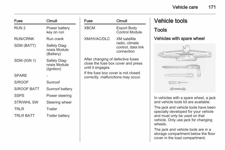
Vehicle care 171
Fuse Circuit
RUN 2 Power batterykey on run
RUN/CRNK Run crank
SDM (BATT) Safety Diag‐nosis Module(Battery)
SDM (IGN 1) Safety Diag‐nosis Module(Ignition)
SPARE -
S/ROOF Sunroof
S/ROOF BATT Sunroof battery
SSPS Power steering
STR/WHL SW Steering wheel
TRLR Trailer
TRLR BATT Trailer battery
Fuse Circuit
XBCM Export BodyControl Module
XM/HVAC/DLC XM satelliteradio, climatecontrol, data linkconnection
After changing of defective fusesclose the fuse box cover and pressuntil it engages.If the fuse box cover is not closedcorrectly, malfunctions may occur.
Vehicle toolsToolsVehicles with spare wheel
In vehicles with a spare wheel, a jackand vehicle tools kit are available.The jack and vehicle tools have beenspecially developed for your vehicleand must only be used on thatvehicle. Only use jack for changingwheels.The jack and vehicle tools are in astorage compartment below the floorcover in the load compartment.
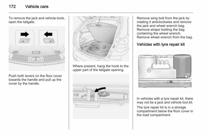
172 Vehicle care
To remove the jack and vehicle tools,open the tailgate.
Push both levers on the floor covertowards the handle and pull up thecover by the handle.
Where present, hang the hook to theupper part of the tailgate opening.
Remove wing bolt from the jack byrotating it anticlockwise and removethe jack and wheel wrench bag.Remove straps holding the bagcontaining the wheel wrench.Remove wheel wrench from the bag.
Vehicles with tyre repair kit
In vehicles with a tyre repair kit, theremay not be a jack and vehicle tool kit.The tyre repair kit is in a storagecompartment below the floor cover inthe load compartment.
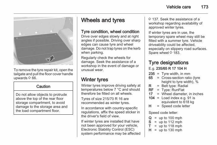
Vehicle care 173
To remove the tyre repair kit, open thetailgate and pull the floor cover handleupwards 3 66.
Caution
Do not allow objects to protrudeabove the top of the rear floorstorage compartment, to avoiddamage to the storage area andthe load compartment floor.
Wheels and tyres
Tyre condition, wheel conditionDrive over edges slowly and at rightangles if possible. Driving over sharpedges can cause tyre and wheeldamage. Do not trap tyres on the kerbwhen parking.Regularly check the wheels fordamage. Seek the assistance of aworkshop in the event of damage orunusual wear.
Winter tyresWinter tyres improve driving safety attemperatures below 7 °C and shouldtherefore be fitted on all wheels.Tyres of size 215/70 R 16 arerecommended as winter tyres.In accordance with country-specificregulations, affix the speed sticker inthe driver's field of view.If winter tyres are installed that havenot been approved for your vehicle,Electronic Stability Control (ESC)system performance may be affected
3 137. Seek the assistance of aworkshop regarding availability ofapproved winter tyres.If winter tyres are in use, thetemporary spare wheel may still befitted with a summer tyre. Vehicledriveability could be affected,especially on slippery road surfaces.Spare wheel 3 183.
Tyre designationsE.g. 235/65 R 17 104 H235 = Tyre width, in mm65 = Cross-section ratio (tyre
height to tyre width), %R = Belt type: RadialRF = Type: RunFlat17 = Wheel diameter, in inches104 = Load index e.g. 91 is
equivalent to 618 kgH = Speed code letter
Speed code letter:Q = up to 100 mphS = up to 112 mphT = up to 118 mphH = up to 130 mph

174 Vehicle care
V = up to 150 mphW = up to 168 mph
Tyre pressureCheck the pressure of cold tyres atleast every 14 days and before anylong journey. Do not forget the sparewheel. This also applies to vehicleswith tyre pressure monitoring system.Use the valve cap key to makeunscrewing the valve caps easier.The valve cap key is located on theinside of the tank flap.Tyre pressure 3 205.The tyre pressure data refers to coldtyres. It applies to summer and wintertyres.Always inflate the spare tyre to thepressure specified for full load.Incorrect tyre pressures will impairsafety, vehicle handling, comfort andfuel economy and will increase tyrewear.
9 Warning
If the pressure is too low, this canresult in considerable tyre warm-up and internal damage, leading totread separation and even to tyreblow-out at high speeds.
If the tyre pressure shall be reducedor increased on a vehicle with tyrepressure monitoring system, switchoff ignition.
Tyre pressure monitoringsystemThe tyre pressure monitoring systemchecks the pressure of all four wheelsonce per minute when vehicle speedexceeds a certain limit.All wheels must be equipped withpressure sensors and the tyres musthave the prescribed pressure. Ifwheels without sensors are mounted,the tyre pressure monitoring systemis not operational. Retrofitting ofsensors is possible.
The current tyre pressures can beshown in the menu item Tyres in theBoard Computer menu. Press theBC button on the Infotainment systemand select the menu item.The tyre pressure monitoring systemautomatically detects the vehicleload. A message appears on theinformation display if inconsistent tyrepressures are detected. In someversions, the message is displayed inabbreviated form.For example, the following messagescan be displayed:

Vehicle care 175
A graphic indicating the left rear tyreis shown together with the current tyrepressure; slight pressure deviation.Reduce speed. Check tyre pressureat next opportunity with anappropriate gauge and correct ifnecessary.On the Colour-Info-Display, thismessage will appear in yellow.
A graphic indicating the front left tyreis shown together with the current tyrepressure; significant pressuredeviation or direct pressure loss.Steer out of the flow of traffic asquickly as possible withoutendangering other vehicles. Stop andcheck the tyres. Mount the sparewheel if necessary 3 180.On the Colour-Info-Display, thismessage will appear in red.Acknowledgement of warnings 3 91,3 93.Vehicle messages 3 99.
If the tyre pressure is to be reduced orincreased, switch off the ignition. Tyrepressures 3 174, 3 205.External high-power radio equipmentcould disrupt the tyre pressuremonitoring system.The tyre pressure monitoring systemvalve cores and sealing rings must bereplaced each time the tyres arechanged.
Temperature compensationCold tyres decrease the tyrepressure, warm tyres increase thetyre pressure. The tyre pressuremonitoring system considers thiseffect for the warning messages.The tyre pressure value shown in thedisplay is the actual tyre pressure.Therefore it is important to check tyrepressure with cold tyres.
Tread depthCheck tread depth at regularintervals.

176 Vehicle care
Tyres should be replaced for safetyreasons at a tread depth of 2-3 mm(4 mm for winter tyres).For safety reasons it is recommendedthat the tread depth of the tyres onone axle should not vary by more than2 mm.
The legally permissible minimumtread depth (1.6 mm) has beenreached when the tread has worndown as far as one of the tread wearindicators (TWI). Their position isindicated by markings on thesidewall.
If there is more wear at the front thanthe rear, swap round front wheels andrear wheels. Ensure that the directionof rotation of the wheels is the sameas before.Tyres age, even if they are not used.We recommend tyre replacementevery 6 years.
Changing tyre and wheelsizeIf tyres of a different size than thosefitted at the factory are used, it may benecessary to reprogramme thespeedometer as well as the nominaltyre pressure and make other vehiclemodifications.After converting to a different tyresize, have the label with tyrepressures replaced.
9 Warning
Use of unsuitable tyres or wheelsmay lead to accidents and willinvalidate the vehicle typeapproval.
If wheel rims of a different type are tobe installed, the wheel nuts may alsoneed to be changed. We recommendyou consult your service partner.
Wheel coversWheel covers and tyres that arefactory approved for the respectivevehicle and comply with all of therelevant wheel and tyre combinationrequirements must be used.If the wheel covers and tyres used arenot factory approved, the tyres mustnot have a rim protection ridge.Wheel covers must not impair brakecooling.
9 Warning
Use of unsuitable tyres or wheelcovers could lead to suddenpressure loss and therebyaccidents.

Vehicle care 177
Tyre chains
Tyre chains are only permitted on thefront wheels.They must be fitted to the tyressymmetrically in order to achieve aconcentric fit.Always use fine mesh chains that addno more than 15 mm to the tyre treadand the inboard sides (including chainlock).
9 Warning
Damage may lead to tyre blowout.
Tyre chains are permitted only on16 inch wheels. We recommend youconsult your service partner.The use of tyre chains is not permittedon the temporary spare wheel.If the use of tyre chains is requiredafter suffering a flat front tyre, fit thetemporary spare wheel on the rearaxle and transfer one of the rearwheels to the front axle.
Tyre repair kitMinor damage to the tyre tread orsidewall can be repaired with the tyrerepair kit.Do not remove foreign bodies fromthe tyres.Tyre damage exceeding 4 mm or thatis at the tyre's sidewall near the rimcannot be repaired with the tyre repairkit.In vehicles with a tyre repair kit, theremay not be a jack and vehicle tool kit.Vehicle tools 3 171.Temporary spare wheel 3 183.
9 Warning
Do not drive faster than 50 mph.Do not use for a lengthy period.Steering and handling may beaffected.
If you have a flat tyre:Apply the electrical parking brake3 135 and engage first gear, reversegear or P.The tyre repair kit is in a storagecompartment below the floor cover inthe load compartment.To remove the tyre repair kit, open thetailgate.Pull the floor cover handle upwards3 66.Vehicle tools 3 171.

178 Vehicle care
Caution
Do not allow objects to protrudeabove the top of the rear floorstorage compartment, to avoiddamage to the storage area andthe load compartment floor.
1. Release the sealant filler hose 1and the power plug 2.
2. Unscrew valve cap from defectivetyre.Screw the sealant filler hose ontothe tyre valve.
3. Connect the power plug to thepower outlet or cigarette lightersocket. Unplug all items fromother power outlets.
4. Switch on ignition. To avoiddischarging the battery, werecommend running the engine.
5. Turn the selector switchanticlockwise to the sealant +air position.
6. Press the on/off button to turn thetyre repair kit on. The tyre is filledwith sealant.The pressure gauge briefly showsa high pressure while the sealantcanister is emptying. Then thepressure starts to drop.All of the sealant is pumped intothe tyre. Then the tyre is inflated.
7. Inflate the tyre to therecommended inflation pressureusing the pressure gauge. Theprescribed tyre pressure shouldbe obtained within 10 minutes3 205. When the correct pressure

Vehicle care 179
is obtained, switch off thecompressor.If the prescribed tyre pressure isnot obtained within 10 minutes,remove the tyre repair kit. Movethe vehicle one tyre rotation.Reattach the tyre repair kit andcontinue the filling procedure for10 minutes. If the prescribed tyrepressure is still not obtained, thetyre is too badly damaged. Seekthe assistance of a workshop.Drain excess tyre pressure withthe button next to the pressuregauge.Do not run the compressor forlonger than 10 minutes.
8. Detach the tyre repair kit andreplace the tyre valve cap.
9. Remove any excess sealantusing a cloth.
10. Take the label indicatingmaximum permitted speed fromthe sealant canister and affix inthe driver's field of view.
11. Continue driving immediately sothat sealant is evenly distributedin the tyre. After driving approx.6 miles (but no more than10 minutes) stop and check tyrepressure.If the tyre pressure has fallenslightly, set it to the correct value.Repeat the procedure until thereis no more loss of pressure.If the tyre pressure has fallen bymore than 10 psi, the vehicle must
not be driven. Seek theassistance of a workshop.
12. To adjust tyre pressure, screwcompressor air hose (arrowed)directly onto tyre valve.

180 Vehicle care
13. Turn the selector switch clockwiseto the air only position. Switch onthe compressor to inflate the tyrewith air only.
NoteThe driving characteristic of therepaired tyre is severely affected,therefore have this tyre replaced.If unusual noise is heard or thecompressor becomes hot, turncompressor off for at least30 minutes.
Note the expiry date of the kit. Afterthis date its sealing capability is nolonger guaranteed. Pay attention tostorage information on sealantcanister.Replace the used sealant canister.To remove sealant canister, releasesealant filler hose and air hose, slidecanister out of housing and unscrewhose from canister. Dispose of thecanister as prescribed by applicablelaws.The accessory adapter supplied canbe used to pump up other itemse.g. footballs, air mattresses,inflatable dinghies etc. The adapteris located on the underside of thetyre repair kit.
Wheel changingSome vehicles are equipped with atyre repair kit instead of a spare wheel3 177.
Make the following preparations andobserve the following information:■ Park the vehicle on a level, firm and
non-slippery surface. The frontwheels must be in the straight-ahead position.
■ Apply the electrical parking brake3 135 and engage first gear,reverse gear or P.
■ Remove the spare wheel 3 183.■ Never change more than one wheel
at a time.■ Block wheel diagonally opposite
the wheel to be changed, by placingwedge blocks or equivalent in frontand behind the wheel.
■ Use the jack only to change wheelsin case of puncture, not forseasonal winter or summer tyrechanges.
■ Never exceed jack maximumworking load (900 kg).
■ If the ground on which the vehicleis standing is soft, a solid board(max. 1 cm thick) should be placedunder the jack.

Vehicle care 181
■ Do not raise the vehicle more thanis necessary to change a wheel.
■ No people or animals may be in thevehicle when it is jacked-up.
■ Never crawl under a jacked-upvehicle.
■ Do not start the engine when it israised on the jack.
■ Clean wheel nuts and thread beforemounting the wheel.
9 Warning
Do not grease wheel bolt, wheelnut and wheel nut cone.
1. Pull off the wheel cover.2. Install the wheel wrench ensuring
that it locates securely and looseneach wheel nut by one turn byturning anticlockwise.
3. The location of front and rearjacking points is indicated bynotches on the bottom edge of thevehicle, under the doors.
4. Before positioning the jack, set itto the necessary height byrotating the eye by hand.Position jack at the jacking pointlocated nearest to the wheelconcerned so that the jack clawspans the vertical base. Ensurethe jack is positioned correctly.The jack base must be on theground directly below the jackingpoint in a manner that prevents itfrom slipping.

182 Vehicle care
5. Attach wheel wrench to eye ofthreaded rod and rotate wrenchclockwise to raise vehicle.If this is not the case, carefullylower the vehicle immediately andreposition the jack. Raise thevehicle until the wheel is just clearof the ground.
6. Unscrew wheel nuts completelyand wipe clean with a cloth.Do not grease the threads. Putwheel nuts somewhere where thethreads will not be soiled.
7. Change the wheel. Notes onspare wheel 3 183.
8. Screw on the wheel nuts andtighten slightly by hand by turningclockwise until wheel is heldagainst the hub.
9. Rotate wrench anticlockwise andlower vehicle to the ground.
10. Install the wheel wrench ensuringthat it locates securely and tighteneach wheel nut in a crosswisesequence. Tightening torque is140 Nm.
11. Stow the replaced wheel 3 183and the vehicle tools 3 171.
12. Check the tyre pressure of theinstalled tyre as soon as possible.
Have the defective tyre renewed andreplace temporary spare wheel with afull specification wheel without delay.
Jacking position for liftingplatform
Rear arm position of the liftingplatform centrically under the recessof the sill.

Vehicle care 183
Front arm position of the liftingplatform centrically under the recessof the sill.
Spare wheelTemporary spare wheelSome vehicles are equipped with atyre repair kit instead of a sparewheel.The temporary spare wheel isdesigned for use on your vehicle only.Use of the temporary spare wheelcould affect driveability, particularly ifusing winter tyres. Have the defective
tyre renewed as soon as possible andhave the wheel balanced and fitted tothe vehicle.
The temporary spare wheel is locatedin the load compartment below thefloor cover and is secured with ascrew-in retainer.Push both levers on the floor covertowards the handle and pull up thecover by the handle. Hang the hookto the upper part of the tailgateopening.Vehicle tools 3 171.
Remove the retainer by rotating itanticlockwise and remove temporaryspare wheel from the spare wheelwell.Only mount one temporary sparewheel. Do not drive faster than50 mph. Take curves slowly. Do notuse for a long period of time.When the temporary spare wheel isfitted, do not take the vehicle throughan automatic vehicle wash with guiderails. The temporary spare wheel mayget caught on the rails, causingdamage to the tyre, wheel and othervehicle parts.The use of tyre chains is not permittedon the temporary spare wheel.Tyre chains 3 177.
Directional tyresFit directional tyres such that they rollin the direction of travel. The rollingdirection is indicated by a symbol(e.g. an arrow) on the sidewall.

184 Vehicle care
The following applies to tyres fittedopposing the rolling direction:■ Driveability may be affected. Have
the defective tyre renewed as soonas possible and have the wheelbalanced and fitted to the vehicle.
■ Do not drive faster than 50 mph.■ Drive particularly carefully on wet
and snow-covered road surfaces.
9 Warning
Storing a jack, a wheel or otherequipment in the loadcompartment could cause injury ifthey are not fixed in placeproperly. During a sudden stop ora collision, loose equipment couldcause personal injury or damageto the vehicle.Always store the jack and vehicletools in their respective storagecompartments and secure themproperly.
Always place the damaged wheelin the load compartment, securedin the spare wheel well with thescrew-in retainer.
Jump startingDo not start with quick charger.A vehicle with a discharged batterycan be started using jump leads andthe battery of another vehicle.
9 Warning
Be extremely careful when startingwith jump leads. Any deviationfrom the following instructions canlead to injuries or damage causedby battery explosion or damage tothe electrical systems of bothvehicles.
9 Warning
Avoid contact of the battery witheyes, skin, fabrics and paintedsurfaces. The fluid containssulphuric acid which can causeinjuries and damage in the eventof direct contact.
■ Never expose the battery to nakedflames or sparks.

Vehicle care 185
■ A discharged battery can alreadyfreeze at a temperature of 0 °C.Defrost the frozen battery beforeconnecting jump leads.
■ Wear eye protection and protectiveclothing when handling a battery.
■ Use a booster battery with thesame voltage (12 Volts). Itscapacity (Ah) must not be muchless than that of the dischargedbattery.
■ Use jump leads with insulatedterminals and a cross section of atleast 16 mm2 (25 mm2 for dieselengines).
■ Do not disconnect the dischargedbattery from the vehicle.
■ Switch off all unnecessary electricalconsumers. The Infotainmentsystem may be damaged ifswitched on while jump starting.
■ Do not lean over the battery duringjump starting.
■ Do not allow the terminals of onelead to touch those of the otherlead.
■ The vehicles must not come intocontact with each other during thejump starting process.
■ Apply the electrical parking brake3 135, transmission in neutral,automatic transmission in P.
■ Open the positive terminalprotection caps of both batteries.
Lead connection order:1. Connect the red lead to the
positive terminal 1 of the boosterbattery.
2. Connect the other end of the redlead to the positive terminal 2 ofthe discharged battery.
3. Connect the black lead to thenegative terminal 3 of the boosterbattery.
4. Connect the other end of the blacklead to a vehicle grounding point,such as the engine block 4 or anengine mounting bolt. Connect asfar away from the dischargedbattery as possible, however atleast 60 cm.
Route the leads so that they cannotcatch on rotating parts in the enginecompartment.To start the engine:1. Start the engine of the vehicle
providing the jump start.2. After 5 minutes, start the other
engine. Start attempts should bemade for no longer than15 seconds at an interval of1 minute.
3. Allow both engines to idle forapprox. 3 minutes with the leadsconnected.

186 Vehicle care
4. Switch on electrical consumers(e.g. headlights, heated rearwindow) of the vehicle receivingthe jump start.
5. Operate discharged vehicle forapprox. 20 minutes to allow foradequate battery recharging.
6. Reverse above sequence exactlywhen removing leads.
TowingTowing the vehicle
The towing eye is located under thefront bumper.Remove the spoiler from the front leftside of the vehicle and attach thetowing eye. Vehicle tools 3 171.Attach a tow rope - or better still a towrod - to the front towing eye, never tothe bumper or front suspension units.Do not tow the vehicle from the rear.The front towing eye must only beused for towing and not recovering avehicle.
Switch on ignition to release steeringwheel lock and to permit operation ofbrake lights, horn and windscreenwiper.Transmission in neutral.Turn key to ignition switch positionACC and release the electricalparking brake before towing thevehicle.
Caution
Drive slowly. Do not drive jerkily.Excessive tractive force candamage the vehicle.
When the engine is not running,considerably more force is needed tobrake and steer.Keep tow rope clear of front bumper,and ensure it is securely fixed to thetowing eye at both ends. Pull on thetow rope to check.To prevent the entry of exhaust fumesfrom the towing vehicle, switch on theair recirculation system 3 115 andclose the windows.

Vehicle care 187
Vehicles with manual transmission:The vehicle must be towed facingforwards. The maximum speed is55 mph. In all other cases, and whenthe transmission is defective, the frontaxle must be raised off the ground.Vehicles with automatic transmission:Do not tow the vehicle using thetowing eye. Towing with a tow ropecould cause severe damage to thetransmission. When towing a vehiclewith automatic transmission, use flatbed or wheel lift equipment.Seek the assistance of a workshop.After towing, unscrew the towing eyeand replace the spoiler. Store towingeye in the storage compartmentbelow the floor cover in the loadcompartment.Vehicle tools 3 171.
Towing another vehicle
Remove the cover located on the rearbumper by pressing the lower part ofthe cover.The rear towing eye attachment isstored below the floor cover in theload compartment.Screw the rear towing eye attachmentanticlockwise using a suitablescrewdriver, until it is firmly in placeand stops in a horizontal position.Attach a tow rope – or better still a towrod – to the rear towing eye.
The towing eye must only be used fortowing and not for recovering avehicle.
Caution
Drive slowly. Do not drive jerkily.Excessive tractive force candamage the vehicle.
To prevent damage, do not take upslack in the tow rope too quickly.After towing, unscrew the rear towingeye attachment clockwise to remove,and reinstall the cover.

188 Vehicle care
Appearance careExterior careLocksThe locks are lubricated at the factoryusing a high quality lock cylindergrease. Use de-icing agent only whenabsolutely necessary, as this has adegreasing effect and impairs lockfunction. After using de-icing agent,have the locks regreased by aworkshop.
WashingThe paintwork of your vehicle isexposed to environmental influences.Wash and wax your vehicle regularly.When using automatic car washes,select a programme that includeswaxing.Bird droppings, dead insects, resin,pollen and the like should be cleanedoff immediately, as they containaggressive constituents which cancause paint damage.
If using a car wash, comply with thecar wash manufacturer's instructions.The windscreen wiper and rearwindow wiper must be switched off.Remove antenna and externalaccessories such as roof racks etc.If you wash your vehicle by hand,make sure that the insides of thewheel housings are also thoroughlyrinsed out.Clean edges and folds on openeddoors and the bonnet as well as theareas they cover.
Caution
Always use a cleaning agent witha pH value of 4 to 9.Do not use cleaning agents on hotsurfaces.
Have the door hinges of all doorsgreased by a workshop.Do not clean the engine compartmentwith a steam-jet or high-pressure jetcleaner.
Thoroughly rinse and leather-off thevehicle. Rinse leather frequently. Useseparate leathers for painted andglass surfaces: remnants of wax onthe windows will impair vision.
Exterior lightsHeadlight and other light covers aremade of plastic. Do not use anyabrasive or caustic agents, do not usean ice scraper, and do not clean themdry.
Polishing and waxingWax the vehicle regularly (at thelatest when water no longer beads).Otherwise, the paintwork will dry out.Polishing is necessary only if the painthas become dull or if solid depositshave become attached to it.Paintwork polish with silicone forms aprotective film, making waxingunnecessary.Plastic body parts must not be treatedwith wax or polishing agents.

Vehicle care 189
Windows and windscreen wiperbladesUse a soft lint-free cloth or chamoisleather together with window cleanerand insect remover.When cleaning the rear window,make sure the heating element insideis not damaged.For mechanical removal of ice, use asharp-edged ice scraper. Press thescraper firmly against the glass sothat no dirt can get under it andscratch the glass.Clean smearing wiper blades with asoft cloth and window cleaner.
SunroofNever clean with solvents or abrasiveagents, fuels, aggressive media(e.g. paint cleaner, acetone-containing solutions etc.), acidic orhighly alkaline media or abrasivepads. Do not apply wax or polishingagents to the sunroof.
Wheels and tyresDo not use high-pressure jetcleaners.
Clean rims with a pH-neutral wheelcleaner.Rims are painted and can be treatedwith the same agents as the body.
Paintwork damageRectify minor paintwork damage witha touch-up pen before rust forms.Have more extensive damage or rustareas repaired by a workshop.
UnderbodySome areas of the vehicle underbodyhave a PVC undercoating while othercritical areas have a durableprotective wax coating.After the underbody is washed, checkthe underbody and have it waxed ifnecessary.Bitumen/rubber materials coulddamage the PVC coating. Haveunderbody work carried out by aworkshop.Before and after winter, wash theunderbody and have the protectivewax coating checked.
Towing equipmentDo not clean the coupling ball bar witha steam-jet or high-pressure jetcleaner.
Rear carrier systemClean the rear carrier system with asteam-jet or high-pressure jet cleanerat least once a year.Operate the rear carrier system oncein a while if not in regular use, inparticular during winter.
Interior careInterior and upholsteryOnly clean the vehicle interior,including the instrument panel fasciaand panelling, with a dry cloth orinterior cleaner.Clean the leather upholstery withclear water and a soft cloth. In case ofheavy soiling, use leather care.The instrument cluster and thedisplays should only be cleaned usinga soft damp cloth.

190 Vehicle care
Clean fabric upholstery with avacuum cleaner and brush. Removestains with an upholstery cleaner.Clothing fabrics may not becolourfast. This could cause visiblediscolourations, especially on light-coloured upholstery. Removablestains and discolourations should becleaned as soon as possible.Clean seat belts with lukewarm wateror interior cleaner.
Caution
Close Velcro fasteners as openVelcro fasteners on clothing coulddamage seat upholstery.The same applies to clothing withsharp-edged objects, like zips orbelts or studded jeans.
Plastic and rubber partsPlastic and rubber parts can becleaned with the same cleaner asused to clean the body. Use interiorcleaner if necessary. Do not use anyother agent. Avoid solvents and petrolin particular. Do not use high-pressure jet cleaners.
Service and maintenance 191
Service andmaintenance
General information ................... 191Recommended fluids, lubricantsand parts .................................... 192
General informationService informationIn order to ensure economical andsafe vehicle operation and tomaintain the value of your vehicle, itis of vital importance that allmaintenance work is carried out at theproper intervals as specified.The detailed, up-to-date serviceschedule for the vehicle is available atthe workshop.
European service intervals
Main serviceMaintenance of your vehicle isrequired every 20,000 miles or after1 year, whichever occurs first.The European service intervals arevalid for the following countries:Andorra, Austria, Belgium, Cyprus,Czech Republic, Denmark, Estonia,Finland, France, Germany, Greece,Greenland, Hungary, Iceland,Ireland, Italy, Latvia, Lithuania,Luxembourg, Malta, Netherlands,
Norway, Poland, Portugal, Slovakia,Slovenia, Spain, Sweden,Switzerland, United Kingdom.
International service intervals
Main ServiceMaintenance of your vehicle isrequired every 10,000 miles or1 year, whichever occurs first.The international service intervals arevalid for the countries which are notlisted in the European serviceintervals.
ConfirmationsConfirmation of service is recorded inthe Service and Warranty Booklet.The date and mileage is completedwith the stamp and signature of theservicing workshop.Make sure that the Service andWarranty Booklet is completedcorrectly as continuous proof ofservice is essential if any warranty orgoodwill claims are to be met, and isalso a benefit when selling thevehicle.

192 Service and maintenance
Recommended fluids,lubricants and partsRecommended fluids andlubricantsOnly use products that meet therecommended specifications.Damage resulting from the use ofproducts not in line with thesespecifications will not be covered bythe warranty.
9 Warning
Operating materials arehazardous and could bepoisonous. Handle with care. Payattention to information given onthe containers.
Engine oilEngine oil is identified by its qualityand its viscosity. Quality is moreimportant than viscosity whenselecting which engine oil to use. Theoil quality ensures e.g. enginecleanliness, wear protection and oil
ageing control, whereas viscositygrade gives information on the oil'sthickness over a temperature range.Dexos is the newest engine oil qualitythat provides optimum protection forgasoline and diesel engines. If it isunavailable, engine oils of other listedqualities have to be used.Recommendations for gasolineengines are also valid for Ethanol(E85) fuelled engines.Select the appropriate engine oilbased on its quality and on theminimum ambient temperature3 196.
Topping up engine oilEngine oils of different manufacturersand brands can be mixed as long asthey comply with the required engineoil quality and viscosity.Use of engine oil with onlyACEA A1/B1 or only A5/B5 quality isprohibited, since it can cause long-term engine damage under certainoperating conditions.
Select the appropriate engine oilbased on its quality and on theminimum ambient temperature3 196.
Additional engine oil additivesThe use of additional engine oiladditives could cause damage andinvalidate the warranty.
Engine oil viscosityThe SAE viscosity grade givesinformation of the thickness of the oil.Multigrade oil is indicated by twofigures, e.g. SAE 5W-30. The firstfigure, followed by a W, indicates thelow temperature viscosity and thesecond figure the high temperatureviscosity.Select the appropriate viscosity gradedepending on the minimum ambienttemperature 3 196.All of the recommended viscositygrades are suitable for high ambienttemperatures.

Service and maintenance 193
Coolant and antifreezeUse only silicate-free long life coolant(LLC) antifreeze. Consult aworkshop.The system is factory filled withcoolant designed for excellentcorrosion protection and frostprotection down to approx. -28 °C. Innorthern countries with very lowtemperatures the factory filled coolantprovides frost protection down toapprox. -37°C. This concentrationshould be maintained all year round.The use of additional coolantadditives that intend to give additionalcorrosion protection or seal againstminor leaks can cause functionproblems. Liability for consequencesresulting from the use of additionalcoolant additives will be rejected.
Brake and clutch fluidOnly use high-performance DOT4+brake fluid approved for the vehicle.Consult a workshop.
Over time, brake fluid absorbsmoisture which will reduce brakingeffectiveness. The brake fluid shouldtherefore be replaced at the specifiedinterval.Brake fluid should be stored in asealed container to avoid waterabsorption.Ensure brake fluid does not becomecontaminated.

194 Technical data
Technical data
Vehicle identification .................. 194Vehicle data ............................... 196
Vehicle identificationVehicle IdentificationNumber
The Vehicle Identification Number isvisible through the windscreen.
The Vehicle Identification Number isalso engraved on the top right-handside of the bulkhead near the centreof the engine firewall.

Technical data 195
Identification plate
The identification label is located onthe front left door frame.
Information on identification label:1 = Manufacturer2 = Type approval number3 = Vehicle Identification Number4 = Permissible gross vehicle
weight rating in kg5 = Permissible gross train weight
in kg6 = Maximum permissible front axle
load in kg7 = Maximum permissible rear axle
load in kg8 = Vehicle-specific or country-
specific data
The combined total of front and rearaxle loads must not exceed thepermissible gross vehicle weight. Forexample, if the front axle is bearing itsmaximum permissible load, the rearaxle can only bear a load that is equalto the gross vehicle weight minus thefront axle load.The technical data is determined inaccordance with EuropeanCommunity standards. We reservethe right to make modifications.
Specifications in the vehicledocuments always have priority overthose given in this manual.

196 Technical data
Vehicle dataRecommended fluids and lubricantsEuropean service schedule
Required engine oil qualityAll European countries
(except Belarus, Moldova, Russia, Serbia, Turkey) Only Israel
Engine oil quality Petrol engines(including E85)
Diesel engines Petrol engines(including E85)
Diesel engines
dexos 1 – – ✔ –
dexos 2 ✔ ✔ – ✔
In case dexos quality is unavailable you may use max. 1 litre engine oil quality ACEA C3 once between each oil change.
Engine oil viscosity gradesAll European countries and Israel(except Belarus, Moldova, Russia, Serbia, Turkey)
Ambient temperature Petrol and diesel engines
down to -25 °C SAE 5W-30 or SAE 5W-40
below -25 °C SAE 0W-30 or SAE 0W-40

Technical data 197
International service schedule
Required engine oil qualityAll countries outside Europe
except Israel Only Belarus, Moldova, Russia, Serbia, Turkey
Engine oil quality Petrol engines(including E85)
Diesel engines Petrol engines(including E85)
Diesel engines
dexos 1 ✔ – – –
dexos 2 – ✔ ✔ ✔
In case dexos quality is unavailable you may use the oil qualities listed below:
All countries outside Europeexcept Israel Only Belarus, Moldova, Russia, Serbia, Turkey
Engine oil quality Petrol engines(including E85)
Diesel engines Petrol engines(including E85)
Diesel engines
GM-LL-A-025 ✔ – ✔ –
GM-LL-B-025 – ✔ – ✔

198 Technical data
All countries outside Europeexcept Israel Only Belarus, Moldova, Russia, Serbia, Turkey
Engine oil quality Petrol engines(including E85)
Diesel engines Petrol engines(including E85)
Diesel engines
ACEA A3/B3 ✔ – ✔ –
ACEA A3/B4 ✔ ✔ ✔ ✔
ACEA C3 ✔ ✔ ✔ ✔
API SM ✔ – ✔ –
API SN resource conserving ✔ – ✔ –
Engine oil viscosity gradesAll countries outside Europe (except Israel),including Belarus, Moldova, Russia, Serbia, Turkey
Ambient temperature Petrol and diesel engines
down to -25 °C SAE 5W-30 or SAE 5W-40
below -25 °C SAE 0W-30 or SAE 0W-40
down to -20 °C SAE 10W-301) or SAE 10W-401)
1) Permitted, but usage of SAE 5W-30 or SAE 5W-40 with dexos quality is recommended.
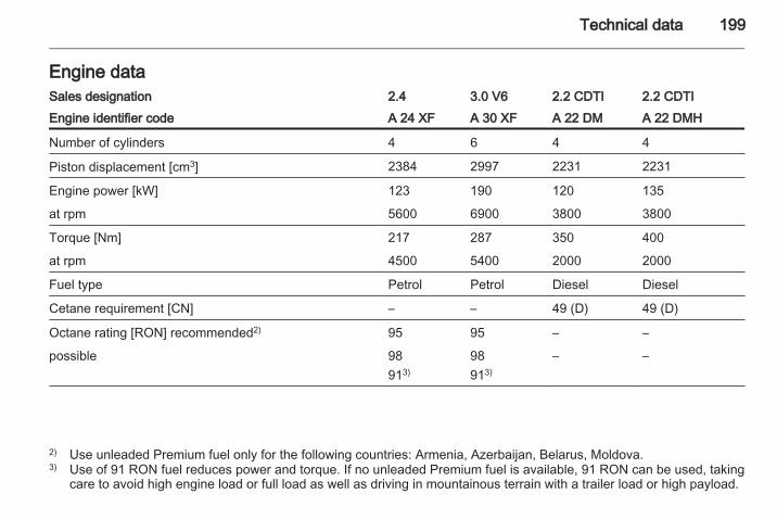
Technical data 199
Engine dataSales designation 2.4 3.0 V6 2.2 CDTI 2.2 CDTIEngine identifier code A 24 XF A 30 XF A 22 DM A 22 DMH
Number of cylinders 4 6 4 4
Piston displacement [cm3] 2384 2997 2231 2231
Engine power [kW] 123 190 120 135
at rpm 5600 6900 3800 3800
Torque [Nm] 217 287 350 400
at rpm 4500 5400 2000 2000
Fuel type Petrol Petrol Diesel Diesel
Cetane requirement [CN] – – 49 (D) 49 (D)
Octane rating [RON] recommended2) 95 95 – –
possible 98913)
98913)
– –
2) Use unleaded Premium fuel only for the following countries: Armenia, Azerbaijan, Belarus, Moldova.3) Use of 91 RON fuel reduces power and torque. If no unleaded Premium fuel is available, 91 RON can be used, taking
care to avoid high engine load or full load as well as driving in mountainous terrain with a trailer load or high payload.

200 Technical data
Sales designation 2.4 3.0 V6 2.2 CDTI 2.2 CDTIEngine identifier code A 24 XF A 30 XF A 22 DM A 22 DMH
Additional fuel type E85 E85 – –
Oil consumption [l/1000 km] 0.6 0.6 0.6 0.6

Technical data 201
PerformanceAll-wheel driveEngine A 24 XF A 30 XF A 22 DM A 22 DMH
Maximum speed4) [mph]
Manual transmission 115 – 116 124
Automatic transmission 109 123 113 119
Front-wheel driveEngine A 24 XF A 30 XF A 22 DM A 22 DMH
Maximum speed4) [mph]
Manual transmission 118 – 117 –
Automatic transmission – – 114 –
4) The maximum speed indicated is achievable at kerb weight (without driver) plus 200 kg payload. Optional equipmentcould reduce the specified maximum speed of the vehicle.

202 Technical data
Vehicle weightKerb weight, basic model without any optional equipmentManual transmission / Automatic transmission.
Engine All-wheel drive Front-wheel drive
A 24 XF 1825-1885 / 1845-1905 1750-1810 / -
A 30 XF - / 1875-1935 - / -
A 22 DM 1911-1971 / 1936-1996 1836-1896 / 1861-1921
A 22 DMH 1911-1971 / 1936-1996 - / -
Vehicle dimensionsLength [mm] 4596
Width [mm] 1850
Height with roof rails [mm] 1761
Height without roof rails [mm] 1717
Wheelbase [mm] 2707
Track width [mm]Front
1569
Rear 1576

Technical data 203
Turning circle diameter, wall to wall [m] 12.78
Turning circle diameter, kerb to kerb [m] 11.87
Maximum wading depth [mm](at 3 mph)
450
Approach angle 20°
Ramp angle 18°
Departure angle 24°

204 Technical data
CapacitiesEngine oilEngine A 24 XF A 30 XF A 22 DM A 22 DMH
including filter [l] 4.7 5.7 5.6 5.6
between MIN and MAX [l] 1.0 1.0 1.0 1.0
Fuel tankPetrol/diesel, nominal capacity [l] 65

Technical data 205
Tyre pressuresUp to full load Up to full load ECO Trailer towing
Engine Tyres front rear front rear front rear[kPa/bar]([psi])
[kPa/bar]([psi])
[kPa/bar]([psi])
[kPa/bar]([psi])
[kPa/bar]([psi])
[kPa/bar]([psi])
All 215/70 R 165),235/65 R 17,235/55 R 18,235/50 R 19
240/2.4 (35) 240/2.4 (35) 260/2.6 (38) 260/2.6 (38) 240/2.4 (35) 280/2.8 (41)
T 155/90 R 166)
(Temporary spare)420/4.2 (60) 420/4.2 (60) – – 420/4.2 (60) 420/4.2 (60)
5) Spare wheel or winter tyres.6) Spare wheel only.

206 Customer information
Customer information
Vehicle data recording and pri‐vacy ........................................... 206
Vehicle data recordingand privacyEvent data recordersData storage modules in thevehicleA large number of electroniccomponents of your vehicle containdata storage modules temporarily orpermanently storing technical dataabout the condition of the vehicle,events and errors. In general, thistechnical information documents thecondition of parts, modules, systemsor the environment:■ Operating conditions of system
components (e.g. filling levels)■ Status messages of the vehicle and
its single components (e.g. numberof wheel revolutions / rotationalspeed, deceleration, lateralacceleration)
■ Dysfunctions and defects inimportant system components
■ Vehicle reactions in particulardriving situations (e.g. inflation ofan airbag, activation of the stabilityregulation system)
■ Environmental conditions (e.g.temperature)
These data are exclusively technicaland help identifying and correctingerrors as well as optimizing vehiclefunctions.Motion profiles indicating travelledroutes cannot be created with thesedata.If services are used (e.g. repairworks, service processes, warrantycases, quality assurance),employees of the service network(manufacturer included) are able toread out this technical informationfrom the event and error data storagemodules applying special diagnosticdevices. If required, you will receivefurther information at theseworkshops. After an error has beencorrected, the data are deleted fromthe error storage module or they areconstantly overwritten.
Customer information 207
When using the vehicle, situationsmay occur in which these technicaldata related to other information(accident report, damages on thevehicle, witness statements etc.) maybe associated with a specific person -possibly with the assistance of anexpert.Additional functions contractuallyagreed upon with the client (e.g.vehicle location in emergency cases)allow the transmission of particularvehicle data from the vehicle.
Radio FrequencyIdentification (RFID)RFID technology is used in somevehicles for functions such as tyrepressure monitoring and ignitionsystem security. It is also used inconnection with conveniences suchas radio remote controls for doorlocking/unlocking and starting, and in-vehicle transmitters for garage dooropeners. RFID technology inVauxhall vehicles does not use orrecord personal information or linkwith any other Vauxhall systemcontaining personal information.

208
Index AAccessories and vehicle
modifications .......................... 149Accessory sockets........................ 77Active head restraints............. 33, 34Adjustable air vents ................... 119Airbag and belt tensioners ........... 83Airbag deactivation ...................... 45Airbag system .............................. 43Air conditioning regular
operation ................................ 120Air conditioning system .............. 115Air intake .................................... 120Air vents...................................... 119All wheel drive ..................... 85, 132Antilock brake system ................ 134Antilock brake system (ABS) ....... 85Anti-theft alarm system .......... 24, 90Anti-theft locking system .............. 23Appearance care........................ 188Apply footbrake ............................ 89Armrest......................................... 39Armrest storage ........................... 55Ashtrays ....................................... 78Automatic anti-dazzle .................. 29Automatic dimming ...................... 28Automatic headlight levelling
system ...................................... 89Automatic level control....... 106, 139
Automatic light control ............... 105Automatic transmission........ 84, 128AUX input..................................... 55
BBattery.................................. 83, 155Battery discharge protection ...... 113Battery, jump starting.................. 184Belt pretensioners......................... 40Belts.............................................. 40Bicycle rack.................................. 55Board-Info-Display ....................... 91Bonnet ....................................... 151Bonnet open................................. 90Brake and clutch fluid................. 192Brake assist ............................... 136Brake fluid .................................. 154Brakes ............................... 134, 154Brake system ............................... 84Breakdown.................................. 186Bulb replacement ....................... 158
CCapacities .................................. 204Card holder................................... 54Cargo management system ........ 67Car Pass ...................................... 18Catalytic converter................ 84, 127CD tray......................................... 54Central locking system ................ 20

209
Centre console storage ............... 55Centre high-mounted brake
light.................................. 109, 162Change engine oil ....................... 88Changing tyre and wheel size . . . 176Charging system .......................... 83Check control................................ 99Child locks ................................... 21Child restraint installation
locations ................................... 49Child restraints.............................. 47Child restraint systems ................ 47Cigarette lighter...................... 55, 78Cleaning the vehicle................... 188Climate control ............................. 14Climate control systems............. 114Clock ............................................ 76Clutch fluid.................................. 154Coin storage................................. 54Console box.................................. 55Console net.................................. 54Control indicators.......................... 80Control of the vehicle ................. 121Controls........................................ 72Controls in steering wheel............ 72Convex shape .............................. 27Coolant and antifreeze............... 192Coupling ball bar........................ 147Cruise control ...................... 90, 139
Cupholders .................................. 53Curtain airbag system .................. 45
DDanger, Warnings and Cautions . . . 3Daytime running lights................ 105Descent control system ....... 86, 138Diesel fuel filter .......................... 157Diesel fuel system bleeding ....... 157Diesel particle filter......... 84, 87, 126Door open .................................... 90Doors............................................ 22Drain fuel filter ............................. 89Drink holders................................ 53Driving characteristics and
towing tips .............................. 145Driving hints................................ 121
EElectric adjustment ...................... 27Electrical parking brake........ 85, 135Electrical parking brake fault........ 85Electrical system......................... 164Electronic climate control
system .................................... 116Electronic driving programmes . . 129Electronic Stability Control . . 86, 137Electronic Stability Control off....... 87End-of-life vehicle recovery ....... 150Engine compartment fuse box ... 165
Engine coolant ........................... 152Engine coolant temperature ........ 87Engine data ............................... 199Engine exhaust .......................... 126Engine oil ................... 151, 192, 196Engine oil life monitor................... 88Engine oil pressure ...................... 87Entry lighting .............................. 112Event data recorders.................. 206Exhaust gases............................ 126Exit lighting ................................ 112Exterior care .............................. 188Exterior lighting .................... 12, 105Exterior mirrors............................. 27
FFault ........................................... 130Fire extinguisher........................... 70First aid kit ................................... 70Fixed air vents ........................... 119Flex-Fix system............................ 55FlexOrganizer............................... 67Fog light ....................................... 90Fog lights.................... 108, 109, 161Folding ......................................... 27Front airbag system ..................... 43Front fog lights ........................... 108Front passenger seat undertray. . . 55Front seats.................................... 34Front storage................................ 54

210
Fuel consumption - CO2-Emissions ............................... 144
Fuel economy mode..................... 88Fuel filler cap................................ 84Fuel for diesel engines .............. 143Fuel for petrol engines ............... 142Fuel gauge ................................... 80Fuses ......................................... 164
GGauges......................................... 79General information ................... 145Glovebox ..................................... 53Graphic-Info-Display, Colour-
Info-Display .............................. 93
HHalogen headlights .................... 158Hand brake................................. 135Hazard warning flashers ............ 107Headlight flash ........................... 106Headlight range adjustment ...... 106Headlights.......................... 106, 158Headlights when driving abroad 107Headlight washer.......................... 73Head restraint adjustment ............. 8Head restraints ............................ 33Heated mirrors ............................. 28Heated rear window ..................... 31Heating ........................................ 38
Heating and ventilation system . 114High beam ........................... 89, 106Hill start assist ........................... 136Horn ....................................... 13, 73
IIdentification plate ..................... 195Ignition switch positions ............. 122Immobiliser ............................ 26, 89Indicators...................................... 79Information displays...................... 91Instrument cluster ........................ 79Instrument panel fuse box ......... 168Instrument panel illumination ..... 163Instrument panel illumination
control .................................... 110Instrument panel overview ........... 10Interior care ............................... 189Interior lighting............................ 110Interior lights ...................... 110, 163Interior mirrors.............................. 28Interruption of power supply ...... 131Introduction .................................... 3ISOFIX child restraint systems .... 52
JJump starting ............................. 184
KKerb weight........................... 70, 202Keys ............................................. 18Keys, locks................................... 18Kickdown.................................... 129
LLashing eyes ............................... 67Light covers, misted.................... 109Lighting....................................... 105Lighting features......................... 112Light switch ................................ 105Load compartment ................ 22, 65Load compartment cover ............. 65Load compartment lighting......... 111Load compartment storage.......... 65Loading information ..................... 70Low engine oil level ..................... 88Low fuel ....................................... 89
MMalfunction indicator light ............ 84Manual anti-dazzle ...................... 28Manual mode ............................. 129Manual transmission .................. 131Mirror adjustment ........................... 9Mirrors.................................... 27, 28Misted light covers ..................... 109

211
NNew vehicle running-in .............. 121Number plate light ..................... 162
OObject detection systems........... 140Octane rating.............................. 199Odometer ..................................... 79Oil............................................... 151Oil, engine.......................... 192, 196Oil life monitor............................... 88Outside temperature .................... 75Overrun cut-off ........................... 123
PParking ................................ 17, 125Parking assist ............................ 140Parking brake....................... 85, 135Parking lights ............................. 109Particulate filter........................... 126Performance .............................. 201Performing work ........................ 150Pollen filter ................................. 120Power outlets ............................... 77Power seat adjustment................. 37Power steering.............................. 86Power steering fluid.................... 153Power windows ............................ 29Preheating ................................... 87Puncture..................................... 180
RRadio Frequency Identification
(RFID)..................................... 207Radio remote control ................... 19Rain sensor.................................. 73Reading lights ............................ 111Rear carrier system...................... 55Rear floor storage cover .............. 66Rear fog light ............................... 90Rear fog lights ........................... 109Rear seats ............................. 38, 39Rear window wiper/washer .......... 75Recommended fluids and
lubricants ........................ 192, 196Reduced engine power................ 89Refuelling ................................... 143Remote control............................. 19Reversing lights ......................... 109Roof.............................................. 31Roof load...................................... 70Roof rack ..................................... 70
SSafety belts................................... 40Safety net .................................... 69Seat adjustment ....................... 6, 35Seat belt ........................................ 8Seat belt reminder.................. 41, 83Seat belts ..................................... 40
Seat folding .................................. 36Seat heating................................. 38Seat position ................................ 34Selector lever ............................. 128Service ............................... 120, 191Service information .................... 191Service vehicle soon .................... 84Side airbag system ...................... 44Sidelights.................................... 105Side turn signal lights ................ 162Spare wheel ............................... 183Speedometer ............................... 79Speed warning.............................. 90Starting and operating................ 121Starting off ................................... 16Starting the engine .................... 122Steering wheel adjustment ...... 9, 72Steering wheel controls ............... 72Stop-start system........................ 123Storage......................................... 53Storage compartments................. 53Sunglasses storage ..................... 54Sunroof ........................................ 31Sunvisor lights ........................... 112Sun visors .................................... 31Symbols ......................................... 4
TTachometer ................................. 80Tailgate......................................... 22

212
Tailgate open ............................... 90Tail lights ................................... 161Technical data............................ 199Three-point seat belt .................... 41Tools .......................................... 171Top-tether fastening eyes ............ 52Towing................................ 145, 186Towing another vehicle ............. 187Towing a trailer........................... 146Towing equipment ..................... 147Towing the vehicle ..................... 186Trailer coupling........................... 145Trailer indicator ............................ 90Trailer stability assist ................. 148Trailer towing ............................. 146Transmission ............................... 15Transmission display ........... 80, 128Tread depth ............................... 175Trip computer in Board-Info-
Display ................................... 100Trip computer in Graphic-Info-
Display or Colour-Info-Display ................................... 101
Trip odometer .............................. 79Turn and lane-change signals ... 108Turn signal ................................... 83Tyre chains ................................ 177Tyre changing............................. 180Tyre designations ...................... 173
Tyre pressure ...................... 99, 174Tyre pressure monitoring
system............................... 99, 174Tyre pressures ........................... 205Tyre repair kit ............................. 177Tyres and wheel size, changing. 176
UUltrasonic parking assist ...... 86, 140Underseat storage ....................... 55Upholstery, cleaning................... 189Upshift.......................................... 85Using this manual .......................... 3
VVehicle checks............................ 150Vehicle data................................ 196Vehicle data recording and
privacy..................................... 206Vehicle dimensions .................... 202Vehicle Identification Number .... 194Vehicle jack................................ 171Vehicle specific data ...................... 3Vehicle storage........................... 149Vehicle tools............................... 171Vehicle unlocking ........................... 6Vehicle weight ........................... 202Ventilation................................... 114
WWarning chimes ........................... 98Warning lights............................... 79Warning triangle .......................... 69Washer and wiper systems ......... 13Washer fluid ............................... 153Washing the vehicle................... 188Welcome lighting........................ 112Wheel changing ......................... 180Wheel covers ............................. 176Wheels and tyres ....................... 173Windows....................................... 29Windscreen................................... 29Windscreen wiper/washer ........... 73Winter tyres ............................... 173Wiper blade replacement .......... 157
XXenon headlights ....................... 160