owner s manual - primus wind power
TRANSCRIPT

AIR 40, AIR Breeze, AIR 30, AIR X MARINE and AIR SILENT-X are trademarks of Primus Wind Power 2013 Primus Wind Power Inc.. AIR Owner’s Manual 3-CMLT-2020-A
OWNER’S MANUAL
Installation · Operation · Maintenance
Primus Wind Power, Inc. 938 Quail Street Lakewood, CO 80215 USA Phone: 303.242.5820 [email protected] www.primuswindpower.com
MADE IN THE USA
2013 Primus Wind Power, Inc.
All Rights Reserved Silent
Manual Release Date: October 2020

AIR 40, AIR Breeze, AIR 30, AIR X MARINE and AIR SILENT-X are trademarks of Primus Wind Power 2013 Primus Wind Power Inc. AIR Owner’s Manual 3-CMLT-2020-A 2
CONTENT: IMPORTANT SAFETY INSTRUCTIONS…………………………….………….4 TECHNICAL SPECIFICATIONS…………………………………………………….5 EXAMPLE OF HYBRID OFF-GRID INSTALL ………………………..……….6 SITING ……………………………………………………………………………..……..7 TOWER HEIGHT / SAFETY TIPS ………………………………………...……..8 TIPS FOR BATTERY BANK SIZING …………………………………...………..9 TURBINE ASSEMBLY /INSTALLATION……………………………………..10-15 Arrival Kit/Packaging………………………………………………...10 Blade to Hub Assembly ……………………………..……………..11-12 Blade Hub to Turbine Assembly ………………………..……..13-14 Turbine to Tower Assembly ……………………………………..15 TOWERS ………………………………………………………………………………..16-18 Tower Options ………………………………………………...……...16 . 27 ft (8.3 m) Tower Kit ……………………………………….…….16 29 ft (8.8 m) Tower Kit ……………………………………..………16 45 ft (13.7 m) Tower Kit ………………………………….….…...17 Marine Tower Kit …………………………………………….…......17 Roof Mounting Kit ……………………………………………………18
WIRING OPTIONS/WIRE SIZING……………………………………………..19-27
Single Turbine Installation………………………………………..19
Single Turbine w/ Up-Tower Junction Box……………….20
Hybrid System Installation………………………………………..21
WIRE SIZING (CONTINUED) Multiple Systems Turbine Installation……………………………...22 Wire Size…………………………………………………………………………..23-25 Stop Switch……………………………………………………………………….26 Fuses, Circuit Breakers, Ammeter …………………………………….27 Turbine Grounding…………………………………………………………...28 Electrodes Driven in Soil……………………………………….29 AIR WIND TURBINE OPERATION …………………………………………………...30-32 Operational Summary ……………………………………………………...30-32 Operating Modes………………………………………………………………30 Voltage Regulation …………………………………………………………...31 Adjusting Regulation Voltage ……………………………….32 Using an Alternate Charge Controller …………………..32 MAINTENANCE ……………………………………………………………………………..33 TROUBLE SHOOTING …………………………………………………………………….34-35 EXPLODED VIEWS & PARTS LIST …………………………………………………...36-41 AIR 40 and AIR Breeze Parts Kits……………………………………….36-38 AIR 30, AIR X marine and Air Silent X Parts Kits …………...…..39-41 WARRANTY…………………………………………………………………………………...42-45 AIR TURBINE UPGRADE KITS & ACCESSORIES APPENDIX A-D………...46-53

AIR 40, AIR Breeze, AIR 30, AIR X MARINE and AIR SILENT-X are trademarks of Primus Wind Power 2013 Primus Wind Power Inc.. AIR Owner’s Manual 3-CMLT-2020-A 3
Primus Wind Power, Inc.
Congratulations on your purchase and welcome to our family!
Dear AIR Owner,
Thank you for your purchase of an AIR wind turbine. You have purchased the most advanced battery charging wind turbine in the world! We believe you will find it easy to install your AIR and are confident you will experience years of dependable service from it.
Before going any further, please complete and return the Warranty Registration Card or register on-line at wwww.primuswindpower.com/warranty. The five-year warranty is effective only after the product has been registered. Note - Primus Wind Power does not sell or distribute your personal information to any third party. We understand and respect your privacy.
If you have any questions or comments, we would like to hear from you. Please call during working hours (Monday-Friday – 8:00 am to 5:00 pm Mountain Standard Time). Our number is (303)-242-5820. You can also email our Customer Service Department at [email protected].
Again, welcome to our family and thank you for investing in the future of wind energy with a Primus Wind Power AIR turbine.
Sincerely,
Primus Wind Power, Inc.
Enter the serial and model numbers below
Serial Number
Model Number
The CE marking is a mandatory compliance requirement in EMEA and the UK and although it is
self-certified, testing and evidence to support that testing is preferred from an independent test
house. All Primus Wind Power turbines are third party tested and fulfil all the relevant provisions
of the following Directives :
Machinery Directive EN60204-1:2006; 2006/42/EC, Low Voltage Directive 2014/35/EU; EMC
2014/30/EU; Immunity Directive EN 61000-6-2:2005; Emissions Directive EN 61000-6-3:2007/
A1:2011,Small Wind Turbine Design Standard EN 61400-2-2014; IEC 61400-02:2013. The report
and the declaration of conformity are available for inspection on request.
The serial number stated on the inside front cover of this owner’s manual refers to a specific
Primus Wind Power product. This product is considered compliant to CE.
Manual Release Date: October 2020
AIR 40, AIR Breeze, AIR 30, AIR X MARINE and AIR SILENT-X are trademarks of Primus Wind Power 2013 Primus Wind Power Inc. AIR Owner’s Manual 3-CMLT-2020-A 4
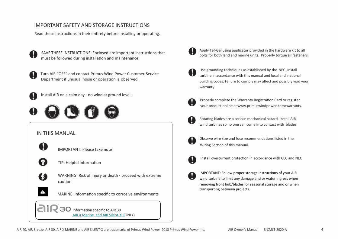
SAVE THESE INSTRUCTIONS. Enclosed are important instructions that must be followed during installation and maintenance.
Turn AIR “OFF” and contact Primus Wind Power Customer Service Department if unusual noise or operation is observed.
Install AIR on a calm day - no wind at ground level.
IN THIS MANUAL
IMPORTANT: Please take note
TIP: Helpful information
WARNING: Risk of injury or death - proceed with extreme
caution
MARINE: Information specific to corrosive environments
Apply Tef-Gel using applicator provided in the hardware kit to all bolts for both land and marine units. Properly torque all fasteners.
Use grounding techniques as established by the NEC. Install
turbine in accordance with this manual and local and national
building codes. Failure to comply may affect and possibly void your
warranty.
Properly complete the Warranty Registration Card or register
your product online at www.primuswindpower.com/warranty.
Rotating blades are a serious mechanical hazard. Install AIR
wind turbines so no one can come into contact with blades.
Observe wire size and fuse recommendations listed in the
Wiring Section of this manual.
Install overcurrent protection in accordance with CEC and NEC
IMPORTANT: Follow proper storage instructions of your AIR
wind turbine to limit any damage and or water ingress when
removing front hub/blades for seasonal storage and or when transporting between projects.
IMPORTANT SAFETY AND STORAGE INSTRUCTIONS
Read these instructions in their entirety before installing or operating.
Information specific to AIR 30 AIR X Marine and AIR Silent-X (ONLY)

AIR 40, AIR Breeze, AIR 30, AIR X MARINE and AIR SILENT-X are trademarks of Primus Wind Power 2013 Primus Wind Power Inc. AIR Owner’s Manual 3-CMLT-2020-A 5
AIR Technical Specifications
Model AIR 40 and AIR Breeze
Weight 13 lb. / 5.9 kg
Rotor Diameter 46 in / 1.17 m
Start Up Wind Speed 7 mph (3.13 m/s)
Kilowatt Hours/month 40 kWh/month @ 12 mph ( 5.5 m/s)
Max. Wind Speed 110 mph (49.2 m/s)
Rated Power 160 watts @ 28 mph (12.5 m/s)
Operating Temperature Range: AIR Breeze and AIR 40 are certified under IEC requirements applying to the temperature range 14° F / (-10° C) to 104º F (40° C). AIR 40 is CSA. IEC & CE certified. NOTE: The AIR wind turbine is designed and has proven performance in temperature ranges of -40°C to 50°C.
Model
Weight
Rotor Diameter
Start Up Wind
Kilowatt Hours/month
Max. Wind Speed
Rated Power
Certifications
AIR 30, AIR X Marine and AIR Silent X
13 lb. / 5.9 kg
46 in / 1.17 m
8 mph (3.59 m/s)
30 kWh/month @ 12 mph (5.5 m/s)
110 mph (49.2 m/s)
400 watts @ 28 mph / 12.5 m/s
CSA, IEC & CE
AIR 30 wind turbines are eligible to bear the CSA mark with “C” and “US” indicators. The “C” and “US” indicators signify that the product has been evaluated to the applicable CSA and ANSI/UL standards for use in Canada and the US.
Voltage Regulation Set Point (factory setting)
12 Volt Systems 14.1 Volts 24 Volt Systems 28.2 Volts
48 Volt Systems 56.4 Volts
Regulator Adjustment Range
12 Volt Systems 13 to 17 volts (approximately) 24 Volt Systems 26 to 34 Volts (approximately)
48 Volt Systems 52 to 68 Volts (approximately)
Recommended Fuse Size (AIR 40 and AIR Breeze) *
TOWER LOADS: Shaft Thrust* 80 lb. @ 100 mph wind speed (230 N @ 45 m/s)
* Install overcurrent protection in accordance with CEC and NEC.
12 Volt Systems 20 amp (slow blow)
24 Volt Systems 10 amp (slow blow)
48 Volt Systems 5 amp (slow blow)
Recommended Fuse Size (AIR 30, AIR X Marine and AIR Silent-X) *
12 Volt Systems 40 amp (slow blow)
24 Volt Systems 25 amp (slow blow)
48 Volt Systems 20 amp (slow blow)

AIR 40, AIR Breeze, AIR 30, AIR X MARINE and AIR SILENT-X are trademarks of Primus Wind Power 2013 Primus Wind Power Inc. AIR Owner’s Manual 3-CMLT-2020-A 6
Please NOTE: AC loads require an inverter
EXAMPLE OF AN OFF-GRID HYBRID INSTALLATION
AIR 40, AIR Breeze, AIR 30, AIR X MARINE and AIR SILENT-X are trademarks of Primus Wind Power 2013 Primus Wind Power Inc. AIR Owner’s Manual 3-CMLT-2020-A 7
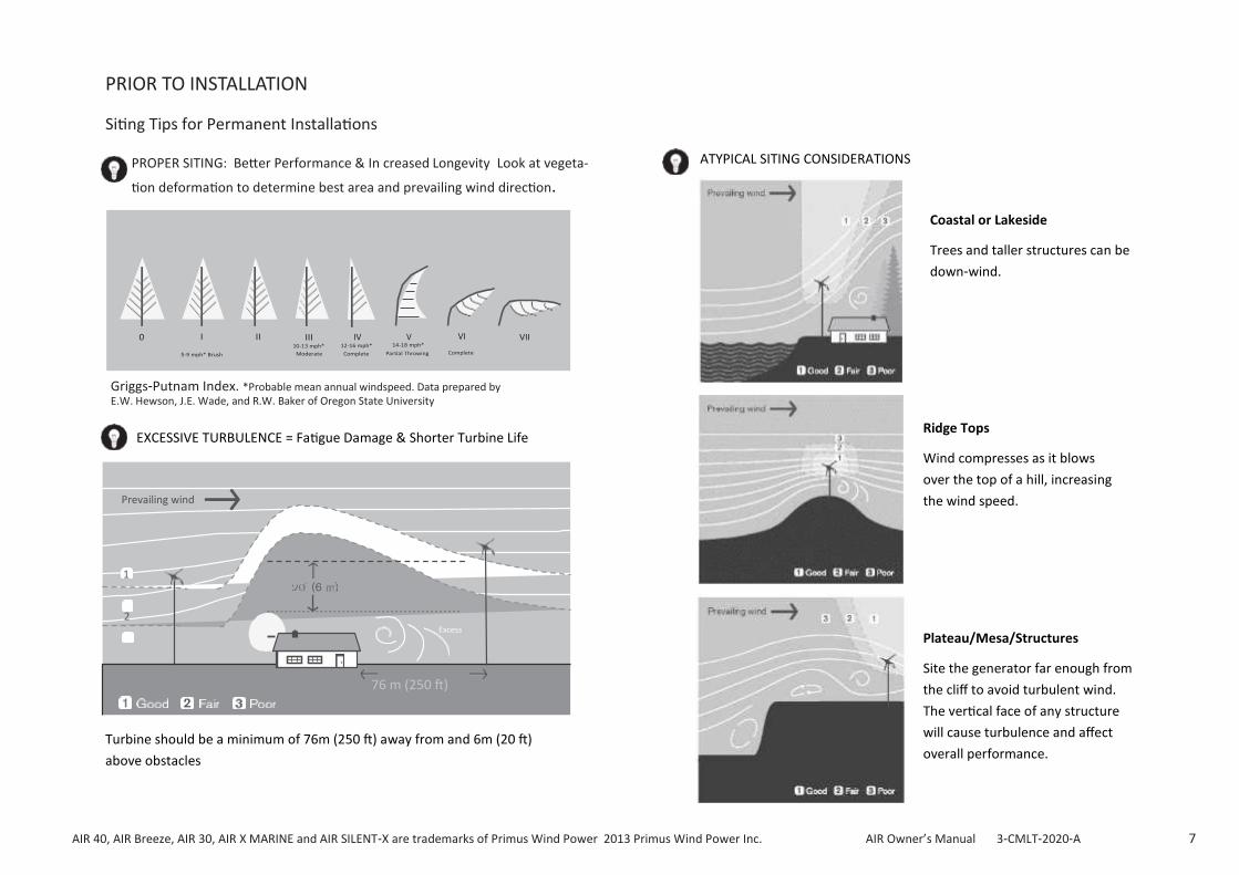
PRIOR TO INSTALLATION
Siting Tips for Permanent Installations
PROPER SITING: Better Performance & In creased Longevity Look at vegeta-
tion deformation to determine best area and prevailing wind direction.
IV VI
Griggs-Putnam Index. *Probable mean annual windspeed. Data prepared by E.W. Hewson, J.E. Wade, and R.W. Baker of Oregon State University
EXCESSIVE TURBULENCE = Fatigue Damage & Shorter Turbine Life
Prevailing wind
1
2
Excess
76 m (250 ft)
Turbine should be a minimum of 76m (250 ft) away from and 6m (20 ft)
above obstacles
ATYPICAL SITING CONSIDERATIONS
Coastal or Lakeside
Trees and taller structures can be
down-wind.
Ridge Tops
Wind compresses as it blows
over the top of a hill, increasing
the wind speed.
Plateau/Mesa/Structures
Site the generator far enough from
the cliff to avoid turbulent wind.
The vertical face of any structure
will cause turbulence and affect
overall performance.

AIR 40, AIR Breeze, AIR 30, AIR X MARINE and AIR SILENT-X are trademarks of Primus Wind Power 2013 Primus Wind Power Inc. AIR Owner’s Manual 3-CMLT-2020-A 8
TOWER SELECTION AND INSTALLATION
Tower Selection
Soil and wind conditions vary; towers and tower foundations must be designed
for your specific location.
Wind speed increases with height. Higher towers also raise generators above
the air turbulence that can exist close to the ground.
Calculations are based on Power Law Exponent 0.02 (in areas of tall row crops,
hedges, a few trees.)
Win
d S
pee
d
Prevent tower climbing by unauthor-
ized persons or children. Never climb
without proper safety equipment.
Always stop the blades before climbing the tower.
Both falling from the tower and contact with the
spinning blades can be lethal.
Tow
er h
eigh
t
THE POWER OF THE WIND: Cube of Wind Speed
The wind speed is extremely important for the amount of energy a wind turbine can convert to elec-tricity: The energy content of the wind varies with the cube (the third power) of the average wind speed, e.g. if the wind speed is twice as high it contains 2 cubed = 2 x 2 x 2 = eight times as much energy.
Wind Power Equation (air density):
WIND POWER = 1/2 x Air Density x Wind Velocity^3 x Swept Area
NOTE: Contact Primus Wind Power for wind resource assessment of your site!

AIR 40, AIR Breeze, AIR 30, AIR X MARINE and AIR SILENT-X are trademarks of Primus Wind Power 2013 Primus Wind Power Inc. AIR Owner’s Manual 3-CMLT-2020-A 9
SIMPLE TIPS FOR DEEP CYCLE BATTERY BANK SIZINING
In preparation for battery sizing, know:
ELECTRICAL USAGE - the amount of energy consumed 1 day in Watt-hours (Wh)
DAYS OF AUTONOMY - days of battery back-up required if unable to charge the batteries by any means.
DEPTH OF DISCHARGE - limit of energy withdrawal to which you will subject the deep cycle battery bank.
• Deeper discharge = Shortened battery life.
• Recommended: never discharge a deep cycle battery below 50% of its capacity
• Off-grid applications, a 25% DoD will extend battery life significantly
TEMPERATURE - Standard for most battery rating is 25 ° C /(77 °F).
• Cold temperatures = reduced battery capacity
• High temperatures = shortened battery life
RECOMMENDATION - Keep the number of parallel strings of batteries to
three or fewer (one is preferred and considered best practice). More than
three strings of batteries, risks shortening battery life due to uneven
charging.
Batteries in Series = Voltage is Additive
Batteries in Parallel = Ah is Additive
*Example: 2 12V 100Ah Battery Bank
Series 24V 100 Ah Parallel 12V 200 Ah
• A system load of 6,000 Watt-hours per day
• 3 Days of Autonomy (back-up) needed
• Planned Depth of Discharge (DoD): 40%
• Battery bank ambient average low 15.6 °C (60 ° F)
CALCULATIONS: calculate battery bank size, use example below:
STEPS: EXAMPLE:
3 days of Autonomy:
6,000 x 3 = 18,000 Wh

AIR 40, AIR Breeze, AIR 30, AIR X MARINE and AIR SILENT-X are trademarks of Primus Wind Power 2013 Primus Wind Power Inc. AIR Owner’s Manual 3-CMLT-2020-A 10
ARRIVAL KIT/PACKAGING
Foam packing Blades
Nose cone in foam packing
Nose cone & blade hub in
Hardware kit
Hardware Kit Content for AIR 40 / AIR Breeze:
• Extra yaw clamp bolts • 5/6 hex wrench
• 1/4-20 (1 3/8) socket head bolts (4) • 3/16 hex wrench
• 1/4-20 Nylock nuts (4) • 5/32 hex wrench
• Flat washers (4) • Tef Gel & Applicator
• Rotor Nut (1)
DIFFERENCES IN HARDWARE FOR AIR 30, AIR X Marine and AIR Silent X:
Different blades and hub
1/4-20 7/8 socket head bolts (7)
1/4-20 Nylock nuts (7)
No flat washers
All marine “AIR” wind turbines contain a stop switch as part of
the hardware kit. All marine turbines have “white” aircraft quality
painted nacelles (AIR Breeze, AIR X Marine and AIR Silent X).

AIR 40, AIR Breeze, AIR 30, AIR X MARINE and AIR SILENT-X are trademarks of Primus Wind Power 2013 Primus Wind Power Inc. AIR Owner’s Manual 3-CMLT-2020-A 11
TURBINE ASSEMBLY
Your AIR wind turbine is delivered partially assembled. Assembly requires:
1. Mounting the blades on the blade hub
2. Securing the hub to the turbine body.
3. Installing the nosecone on the blade hub. The necessary hex
(Allen) wrenches are furnished with your AIR wind turbine.
STEP 1: Blade to Hub Assembly
NOTE: Attach all blades to the blade hub following the directions depicted.
(See Figure 1 for AIR Breeze/AIR 40 procedure and Figure 2 for AIR 30 procedure.)
WARNING: Nylock nuts and greased blade bolts may only be used one time; replace after each use.
1- AIR 30 blade hub
2- AIR 30, AIR X blade
3- 1/4 - 20 socket head cap bolt (2)
4- 1/4 - Nylock nut (2)
Fig. 2 AIR 30,AIR X Marine and AIR Silent X wind turbine Blade Attachment Detail.
Torque Specifications:
Blade to hub bolts, 1/4-20 x 0.875 inch, Socket Head Bolt, 72 in-lb. (8.0 Nm)
Hub to rotor nut, 5/8-18, 40 lb.-ft (55 Nm)
Fig. 1 AIR Breeze & AIR 40 wind turbine Blade Attachment Detail.
Torque Specifications:
Blade to hub bolt, 1/4 - 20 x 1.375, socket head bolt 72 in-lb. (8.0 Nm)
Hub to rotor nut, 5/8-18, 40lb-ft (55 Nm)
and AIR X (see Appendix A for AIR Silent X installation

AIR 40, AIR Breeze, AIR 30, AIR X MARINE and AIR SILENT-X are trademarks of Primus Wind Power 2013 Primus Wind Power Inc. AIR Owner’s Manual 3-CMLT-2020-A 12
Blade to Hub Assembly (STEP 1)
3/16”
Assembled blade
WARNING: Nylock nuts and greased blade bolts may only be used
one time; replace after each use.
NOTE: See Appendix B: AIR Silent X Blade Set and Further Installation Recommendations
Assembly blade set first using proper torque for hardware and
application of tef-gel included.
AIR 30 and AIR X Marine units, it is recommended to perform tip to tip
measurment of blades prior to properly securing hub to avoid vibration.
The hub blade root allows for adjustment of the blade position. There-
fore, it is recommended to adjust the distance between each blade tip.
The blades should have a distance from blade tip to blade tip approxi-
mately equal between all three blades.
and AIR X Marine
IMPORTANT: Tef-Gel is a corrosion inhibitor and is especially important in marine applications. Tef-Gel should be applied to all blade bolts and yaw bolts using the applicator and Tef-Gel provided with your hardware kit. Tef-Gel helps to pre-vent corrosion and lubricates threads (recommended for both land and marine usage).

AIR 40, AIR Breeze, AIR 30, AIR X MARINE and AIR SILENT-X are trademarks of Primus Wind Power 2013 Primus Wind Power Inc. AIR Owner’s Manual 3-CMLT-2020-A 13
TURBINE ASSEMBLY
STEP 2: Mount Blade Hub to Turbine
Assembled blade hub
Rotor shaft
1.) Coat rotor shaft threads and blade hub with Tef Gel.
2.) Slide blade hub onto rotor shaft.
5.) Insert 5/16” hex wrench in rotor shaft.
6.) Carefully and slowly “spin” the blades to completely secure the blade hub to the turbine.
7.) Apply the following torque when tightening the Rotor Jam Nut using torque wrench at 40 ft.lbs. / 55 Nm.
3.) Start 5/8-18 jam nut on rotor shaft.
4.) Carefully and slowly “spin” the blades to begin tightening the nut.
IMPORTANT: Observe torque specs
NOTE: When The Shaft and Face are exposed, apply a liberal amount of synthetic grease to the gap around Shaft and Bearing on the Face of the turbine (this should be performed as a regular maintenance event every 12 months). See FAQ section on storage kit recommendations and Appendix C
IMPORTANT: Tef-Gel is a corrosion inhibitor and is especially important in marine applications. Tef-Gel should be applied to all blade bolts and yaw bolts using the applicator and Tef-Gel provid-ed with your hardware kit. Tef-Gel helps to prevent corrosion and lubricates threads (recommended for both land and marine us-age).
AIR 40, AIR Breeze, AIR 30, AIR X MARINE and AIR SILENT-X are trademarks of Primus Wind Power 2013 Primus Wind Power Inc. AIR Owner’s Manual 3-CMLT-2020-A 14
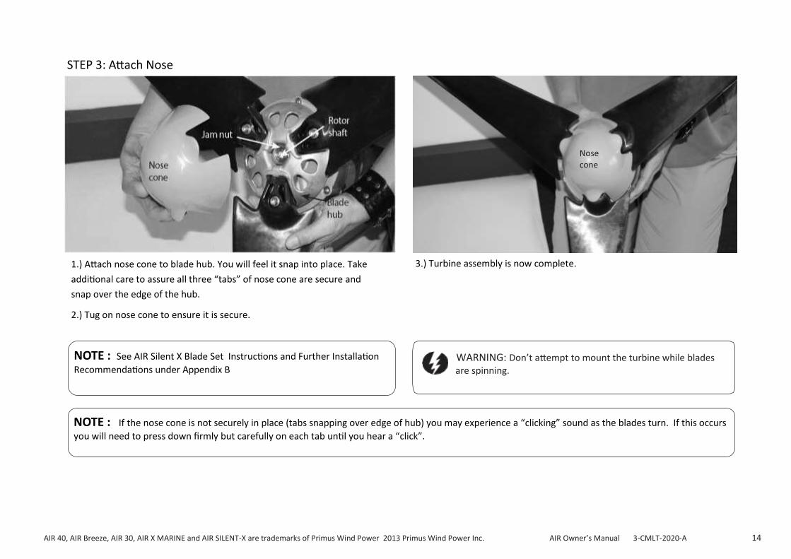
STEP 3: Attach Nose
1.) Attach nose cone to blade hub. You will feel it snap into place. Take
additional care to assure all three “tabs” of nose cone are secure and
snap over the edge of the hub.
2.) Tug on nose cone to ensure it is secure.
Nose cone
3.) Turbine assembly is now complete.
NOTE : See AIR Silent X Blade Set Instructions and Further Installation
Recommendations under Appendix B
NOTE : If the nose cone is not securely in place (tabs snapping over edge of hub) you may experience a “clicking” sound as the blades turn. If this occurs
you will need to press down firmly but carefully on each tab until you hear a “click”.
WARNING: Don’t attempt to mount the turbine while blades are spinning.

AIR 40, AIR Breeze, AIR 30, AIR X MARINE and AIR SILENT-X are trademarks of Primus Wind Power 2013 Primus Wind Power Inc. AIR Owner’s Manual 3-CMLT-2020-A 15
Yaw pivot & clamp
Tower tubing
M5 Socket head screw 5/32” (comes imbedded in Hex yaw assembly) wrench
STEP 4: Attach Turbine to Tower
4.) Insert tower into yaw assembly.
5.) Ensure yaw pad is in place.
6.) Apply Tef-Gel w/ applicator provided to yaw bolts prior to assembly.
Tighten screws to secure turbine to tower. It is important that Tef-Gel
is applied to all hardware prior to final assembly.
7.) Ensure turbine is securely attached to tower.
8.) Ensure wire connections are secure and double check for initial two
blinks by “powering up” turbine prior to raising the tower. This is especially
important when installed on boats or structures.
1.) Insert yaw pad into yaw pivot point/clamp assembly.
2.) NOT SHOWN: Complete turbine wiring connections.
3.) After assembling the yaw clamp, insert yaw/wires into the tower, lift
the yaw clamp assembly 1/8” to secure the yaw onto yaw pad to prevent
metal to metal contact and reduce vibration down-tower. This is espe-
cially important when mounted on boat or structures.
IMPORTANT: Apply Tef-Gel to yaw bolts prior to assembly.
Observe torque specs during assembly.
WARNING: The yaw pad is critical to ensuring proper and secure turbine mounting to the tower; however, in some instances it makes it difficult to tell if the tower is properly inserted into the yaw assembly. Check this carefully before raising the tower.
IMPORTANT: Further inspection of the blade bolts, yaw bolts and
rotor nut are recommended and re-tightened within 30 days after
initial installation.

AIR 40, AIR Breeze, AIR 30, AIR X MARINE and AIR SILENT-X are trademarks of Primus Wind Power 2013 Primus Wind Power Inc. AIR Owner’s Manual 3-CMLT-2020-A 16
AIR WIND TURBINE TOWERS
1. The AIR wind turbine mounts on tubing with a nominal 1.875 – 1.900
inch outside diameter.
2. Typical tower construction use: 1 1/2 inch Schedule 40 steel pipe or 2 inch
SS-20 galvanized fence tubing (0.090 inch wall thickness) or equivalent.
3. DO NOT use plastic pipe to construct a tower or electrical conduit.
LAND TOWER OPTIONS
Primus Wind Power offers a number of tower choices for your AIR wind turbine.
The following section provides a summary of the available tower kits. User manuals
for the towers and tower kits are available online and you are encouraged to review
them in order to make the most informed tower selection.
27 ft (8.3 m) Tower Kit
The 27 ft (8.3 m) Tower Kit includes a tower clamp/guy wire assembly and all neces-
sary hardware and fasteners to erect a 27 ft tilt-up tower using Schedule 40 steel pipe
or tubing with an outside diameter of 1.875 inch. See Fig. 3.
Note: Anchors and tubing are not furnished with the kit.
29 ft (8.8 m) EZ – Tower
The 29 ft (8.8 m) EZ Tower is a complete kit that includes all materials required to as-
semble a 29 ft guy wire tilt-up tower. Anchors, guy wire assemblies, galvanized steel
tubing and all fasteners. See Fig. 4. Fig. 4. 29 ft (8.8 m) Tower Kit
IMPORTANT: User manuals for towers and tower kits are available online a www.primuswindpower.com. Primus Wind Power recommends reviewing
them to make an appropriate tower selection for your AIR wind turbine.

AIR 40, AIR Breeze, AIR 30, AIR X MARINE and AIR SILENT-X are trademarks of Primus Wind Power 2013 Primus Wind Power Inc. AIR Owner’s Manual 3-CMLT-2020-A 17
AIR WIND TURBINE TOWERS (continued)
45 ft (13.7 m) Tower Kit
The 45 ft (13.7 m) Tower Kit includes tower clamp/guy wire assemblies
and all necessary hardware and fasteners to erect a 45 ft tilt-up tower
using Schedule 40 steel pipe or tubing with an outside diameter
of 1.875 inch. See Fig. 5.
Note: Anchors and pipe or tubing are not furnished.
MARINE TOWER KIT
The Marine Tower Kit is specifically designed to aid mounting the turbine on a boat deck. Kit includes powder coated alumi-num mast and stays, vibration damping mounts and all neces-sary marine grade hardware to install the kit. See Fig. 6.
Marine towers components are sold in two kits:
1) Marine grade Pole and Mast Set /Stay Kit
2) Marine grade hardware and mounting brackets (SS)
Fig. 5. 45 ft (13.7 m) Tower Kit
IMPORTANT: User manuals for towers and tower kits are available online at www.primuswindpower.com. Primus Wind Power recom-mends reviewing user manuals prior to purchase to make an appro-priate tower selection for your AIR wind turbine.
Fig. 6. Marine Tower Kit

AIR 40, AIR Breeze, AIR 30, AIR X MARINE and AIR SILENT-X are trademarks of Primus Wind Power 2013 Primus Wind Power Inc. AIR Owner’s Manual 3-CMLT-2020-A 18
ROOF MOUNT KIT
The Roof Mount Kit allows the pole for your AIR wind turbine to be mounted to the wall or roof truss of a structure and extend above its roofline. The kit includes isolators, base plates and all hardware, clamps and straps.
Your AIR can be mounted flush to the side of the structure or via a penetrating hole through the roof or eaves. If mounted via penetrating hole, we recom-mend purchasing the roof mount kit with seal. See Fig. 7.
Fig. 7. Roof Mounting Kit
TOWER LEVELING
When installing a tower it is important that both the tower and turbine are properly level. If not properly leveled this can affect both performance and power output.
In addition to power output being affected there is the potential the blades could rotate in the opposite direction loosening the rotor nut creating a safety concern.
NOTE: if the turbine is not level the turbine will always settle in the off-level position, causing reduced power and performance.
TIP: Installing wind turbine using roof mount kit tower or on a building can affect performance due to in-creased turbulence.

AIR 40, AIR Breeze, AIR 30, AIR X MARINE and AIR SILENT-X are trademarks of Primus Wind Power 2013 Primus Wind Power Inc. AIR Owner’s Manual 3-CMLT-2020-A 19
Amp Meter
User Power Center Junction Box
Battery Disconnect
Fuse or Breaker
Stop Switch
Battery Bank
Turbine Positive
Red Lead
Turbine Negative
Black Lead
Chassis Ground
Ground Rod
AIR
Wind Turbine
Generator
Tower
Tower Ground
Turbine Ground
Green Lead
Earth Ground
Fig. 8 Single Turbine Installation
AIR WIND TURBINE WIRING OPTIONS
The recommended way to connect the turbine to your battery
bank is to wire the turbine directly to its own set of battery posts;
allowing the turbine to operate independently. The AIR turbine’s internal
regulator will monitor the battery and maintain the charge as nec-essary.
Figs. 8 and 9 represent typical single turbine installations. Fig. 9 includes an up-tower junction box for UL (Underwriters Laboratory) compliance.
NOTE: Contact Primus Wind Power for more information about this configuration.

AIR 40, AIR Breeze, AIR 30, AIR X MARINE and AIR SILENT-X are trademarks of Primus Wind Power 2013 Primus Wind Power Inc. AIR Owner’s Manual 3-CMLT-2020-A 20
TIP: It is recommended for longer wire runs to utilize the 24V or 48V tur-bines due to reduced wire size. All AIR turbines are voltage specific and not field adjustable.
TIP: It is recommended to include a lighting arrestor with your installation.
See FAQ section at www.primuswindpower.com for recommendations.

AIR 40, AIR Breeze, AIR 30, AIR X MARINE and AIR SILENT-X are trademarks of Primus Wind Power 2013 Primus Wind Power Inc. AIR Owner’s Manual 3-CMLT-2020-A 21
HYBRID SYSTEM WIRING
Fig. 10 represents a typical “hybrid” system with solar panels. Some charg-ing sources (solar panels, fuel-powered generators, additional wind generators, etc.) connected to the same system may interfere with the AIR turbine’s internal charge regula-tion process. This will not harm the turbine, however it may spin slowly as if “braked” or may stop completely. Test for possible interference by dis-connecting the other charging sources to determine the possible cause. Contact Primus Wind Power Customer Service for guidance.
TIP: In this figure the AIR wind
turbine internal regulator is used.
A diversion type external regula-
tor could also have been used.
TIP: Voltage “pre-regulation” may
be prevented by increasing the
regulation set point.
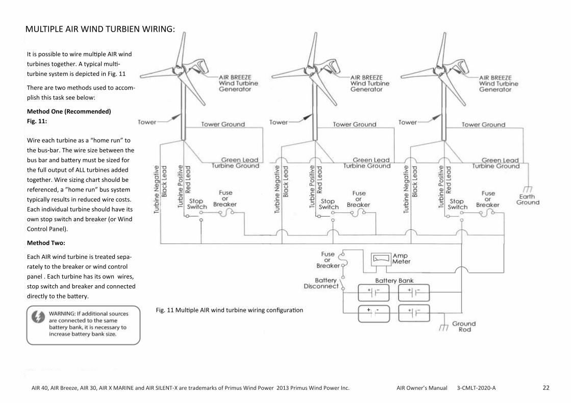
WARNING: If additional sources are
connected to the same battery
bank, it is necessary to increase
battery bank size.
AIR 40, AIR Breeze, AIR 30, AIR X MARINE and AIR SILENT-X are trademarks of Primus Wind Power 2013 Primus Wind Power Inc. AIR Owner’s Manual 3-CMLT-2020-A 22
+ -
It is possible to wire multiple AIR wind
turbines together. A typical multi-
turbine system is depicted in Fig. 11
There are two methods used to accom-
plish this task see below:
Method One (Recommended)
Fig. 11:
Wire each turbine as a “home run” to
the bus-bar. The wire size between the
bus bar and battery must be sized for
the full output of ALL turbines added
together. Wire sizing chart should be
referenced, a ”home run” bus system
typically results in reduced wire costs.
Each individual turbine should have its
own stop switch and breaker (or Wind
Control Panel).
Method Two:
Each AIR wind turbine is treated sepa-
rately to the breaker or wind control
panel . Each turbine has its own wires,
stop switch and breaker and connected
directly to the battery.
Fig. 11 Multiple AIR wind turbine wiring configuration
MULTIPLE AIR WIND TURBIEN WIRING:
AIR 40, AIR Breeze, AIR 30, AIR X MARINE and AIR SILENT-X are trademarks of Primus Wind Power 2013 Primus Wind Power Inc. AIR Owner’s Manual 3-CMLT-2020-A 23
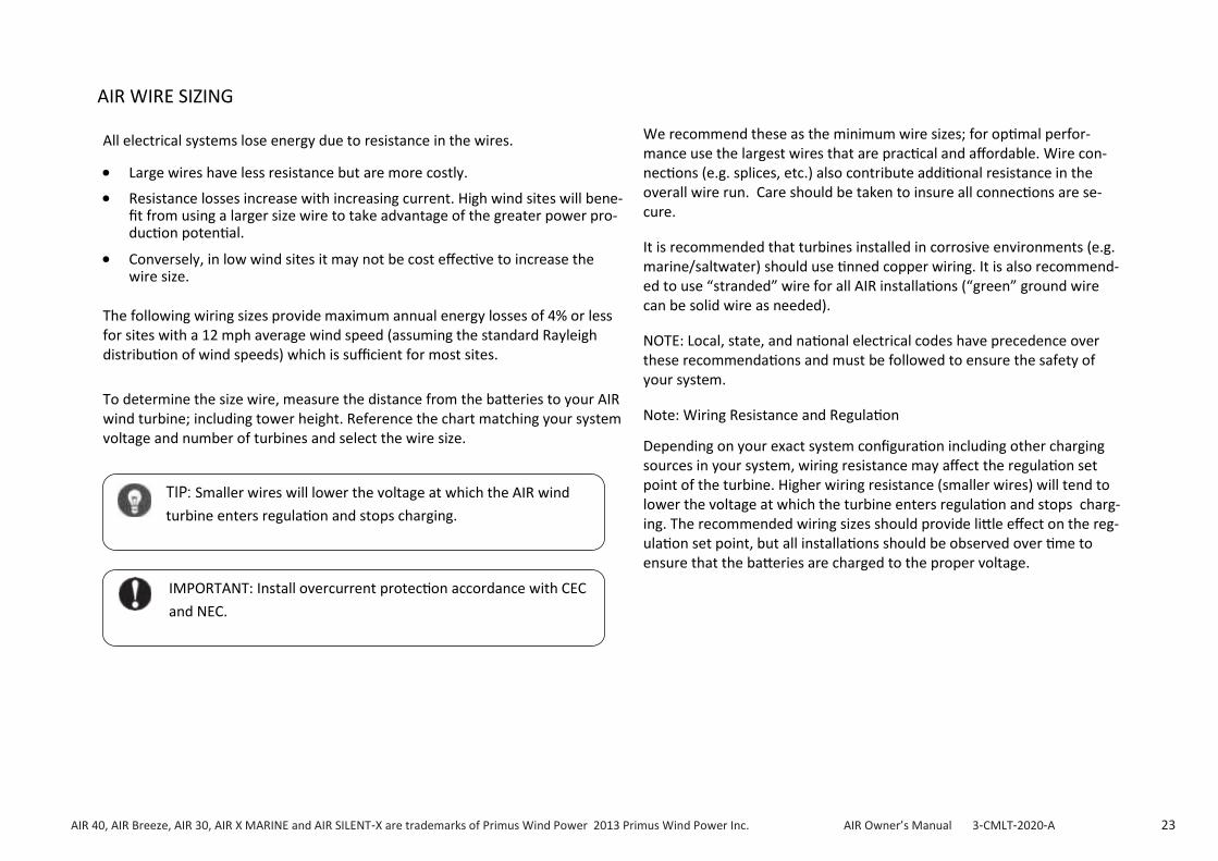
AIR WIRE SIZING
All electrical systems lose energy due to resistance in the wires.
• Large wires have less resistance but are more costly.
• Resistance losses increase with increasing current. High wind sites will bene-fit from using a larger size wire to take advantage of the greater power pro-duction potential.
• Conversely, in low wind sites it may not be cost effective to increase the wire size.
The following wiring sizes provide maximum annual energy losses of 4% or less for sites with a 12 mph average wind speed (assuming the standard Rayleigh distribution of wind speeds) which is sufficient for most sites.
To determine the size wire, measure the distance from the batteries to your AIR wind turbine; including tower height. Reference the chart matching your system voltage and number of turbines and select the wire size.
We recommend these as the minimum wire sizes; for optimal perfor-mance use the largest wires that are practical and affordable. Wire con-nections (e.g. splices, etc.) also contribute additional resistance in the overall wire run. Care should be taken to insure all connections are se-cure.
It is recommended that turbines installed in corrosive environments (e.g. marine/saltwater) should use tinned copper wiring. It is also recommend-ed to use “stranded” wire for all AIR installations (“green” ground wire can be solid wire as needed).
NOTE: Local, state, and national electrical codes have precedence over these recommendations and must be followed to ensure the safety of your system.
Note: Wiring Resistance and Regulation
Depending on your exact system configuration including other charging sources in your system, wiring resistance may affect the regulation set point of the turbine. Higher wiring resistance (smaller wires) will tend to lower the voltage at which the turbine enters regulation and stops charg-ing. The recommended wiring sizes should provide little effect on the reg-ulation set point, but all installations should be observed over time to ensure that the batteries are charged to the proper voltage.
IMPORTANT: Install overcurrent protection accordance with CEC
and NEC.
TIP: Smaller wires will lower the voltage at which the AIR wind
turbine enters regulation and stops charging.

AIR 40, AIR Breeze, AIR 30, AIR X MARINE and AIR SILENT-X are trademarks of Primus Wind Power 2013 Primus Wind Power Inc. AIR Owner’s Manual 3-CMLT-2020-A 24
Number of
Turbines:
0-30 ft (/
0-9 m)
30ft-60ft /
(9-18 m)
60ft-90ft (/
18-27 m)
90ft-150 ft /
(27-46 m)
150ft-190ft /
(46-58 m)
190ft-250 ft/
(58-76 m)
250 ft-310 ft /
(76-95 m)
310ft-390 ft /
(95-119 m)
390ft-500ft /
(119-152 m)
1
10/6 mm2
8/10 mm2
4/25 mm2 2/35 mm2 2/35 mm2 1/50 mm2 0/50 mm2 00/70 mm2 000/95 mm2
2 6/16 mm2
4/25 mm2
2/35 mm2 0/50 mm
2 00/70 mm
2 000/95 mm
2 0000/120 mm
2 *** ***
3 4/25 mm2 2/35 mm
2 0/50 mm
2 000/95 mm
2 0000/120 mm
2 *** *** *** ***
Number of
Turbines:
0-30 ft /
(0-9 m)
30ft-60ft /
(9-18 m)
60ft-90ft /
(18-27 m)
90ft-150 ft /
(27-46 m)
150ft-190ft /
(46-58 m)
190 ft-250 ft /
(58-76 m)
250 ft-310 ft /
(76-95 m)
310ft-390 ft /
(95-119 m)
390ft-500ft /
(119-152 m)
1 14/2.5 mm
2
12/4 mm2 10/6 mm
2 8/10 mm
2 8/10 mm
2 6/16 mm
2 6/16 mm
2 4/25 mm
2 4/25 mm
2
2 12/4 mm2 10/6 mm
2 8/10 mm
2 6/16 mm
2 4/25 mm
2 2/35 mm
2 2/35 mm
2 1/50 mm
2 0/50 mm
2
3 10/6 mm2 8/10 mm
2 6/16 mm
2 4/25 mm
2 2/35 mm
2 2/35 mm
2 1/50 mm
2 0/50 mm
2 00/70 mm
2
Number of
Turbines:
0-30 ft /
(0-9 m)
30ft-60ft /
(9-18 m)
60ft-90ft /
(18-27 m)
90ft-150 ft /
(27-46 m)
150ft-190ft /
(46-58 m)
190 ft-250 ft /
(58-76 m)
250 ft-310 ft /
(76-95 m)
310ft-390 ft /
(95-119 m)
390ft-500ft /
(119-152 m)
1 14/2.5 mm2 14/2.5 mm
2 14/2.5mm
2 14/2.5 mm
2 14/2.5 mm
2 12/4 mm
2 12/4 mm
2 10/6 mm
2 10/6 mm
2
2 14/2.5 mm2 14/2.5 mm
2 14/2.5 mm
2 12/4 mm
2 10/6 mm
2 8/10 mm
2 8/10 mm
2 8/10 mm
2 6/16 mm
2
3 14/2.5 mm2 14/2.5 mm
2 12/4 mm
2 10/6 mm
2 8/10 mm
2 8/10 mm
2 6/16 mm
2 6/16 mm
2 4/25 mm
2
AND AIR BREEZE
24 Volt System, AWG / Metric Wire Size mm2
48 Volt System, AWG / Metric Wire Size mm2
12 Volt System, AWG / Metric Wire Size mm2
Refer back to page 22 for multiple turbine install options. It is recommended that each turbine is installed on a “home“ run per option one for best practice installation.
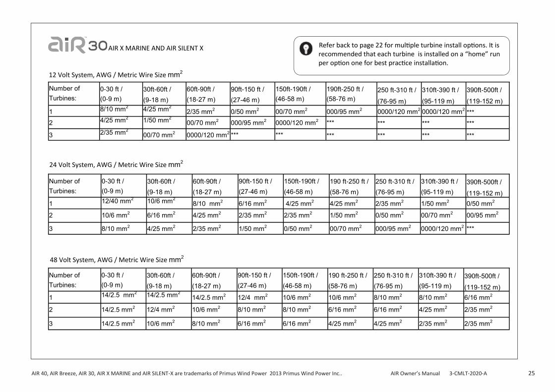
AIR 40, AIR Breeze, AIR 30, AIR X MARINE and AIR SILENT-X are trademarks of Primus Wind Power 2013 Primus Wind Power Inc.. AIR Owner’s Manual 3-CMLT-2020-A 25
AIR X MARINE AND AIR SILENT X
Number of
Turbines:
0-30 ft /
(0-9 m)
30ft-60ft /
(9-18 m)
60ft-90ft /
(18-27 m)
90ft-150 ft /
(27-46 m)
150ft-190ft /
(46-58 m)
190ft-250 ft /
(58-76 m)
250 ft-310 ft /
(76-95 m)
310ft-390 ft /
(95-119 m)
390ft-500ft /
(119-152 m)
1 8/10 mm2 4/25 mm2 2/35 mm2 0/50 mm2 00/70 mm2 000/95 mm2 0000/120 mm2 0000/120 mm2 ***
2 4/25 mm2 1/50 mm
2 00/70 mm
2 000/95 mm
2 0000/120 mm
2 *** *** *** ***
3 2/35 mm2 00/70 mm
2 0000/120 mm
2 *** *** *** *** *** ***
Number of
Turbines:
0-30 ft /
(0-9 m)
30ft-60ft /
(9-18 m)
60ft-90ft /
(18-27 m)
90ft-150 ft /
(27-46 m)
150ft-190ft /
(46-58 m)
190 ft-250 ft /
(58-76 m)
250 ft-310 ft /
(76-95 m)
310ft-390 ft /
(95-119 m)
390ft-500ft /
(119-152 m)
1 12/40 mm2 10/6 mm
2 8/10 mm
2 6/16 mm
2 4/25 mm
2 4/25 mm
2 2/35 mm
2 1/50 mm
2 0/50 mm
2
2 10/6 mm2 6/16 mm
2 4/25 mm
2 2/35 mm
2 2/35 mm
2 1/50 mm
2 0/50 mm
2 00/70 mm
2 00/95 mm
2
3 8/10 mm2 4/25 mm
2 2/35 mm
2 1/50 mm
2 0/50 mm
2 00/70 mm
2 000/95 mm
2 0000/120 mm
2 ***
Number of
Turbines:
0-30 ft /
(0-9 m)
30ft-60ft /
(9-18 m)
60ft-90ft /
(18-27 m)
90ft-150 ft /
(27-46 m)
150ft-190ft /
(46-58 m)
190 ft-250 ft /
(58-76 m)
250 ft-310 ft /
(76-95 m)
310ft-390 ft /
(95-119 m)
390ft-500ft /
(119-152 m)
1 14/2.5 mm2 14/2.5 mm
2 14/2.5 mm
2 12/4 mm
2 10/6 mm
2 10/6 mm
2 8/10 mm
2 8/10 mm
2 6/16 mm
2
2 14/2.5 mm2 12/4 mm
2 10/6 mm
2 8/10 mm
2 8/10 mm
2 6/16 mm
2 6/16 mm
2 4/25 mm
2 2/35 mm
2
3 14/2.5 mm2 10/6 mm
2 8/10 mm
2 6/16 mm
2 6/16 mm
2 4/25 mm
2 4/25 mm
2 2/35 mm
2 2/35 mm
2
48 Volt System, AWG / Metric Wire Size mm2
24 Volt System, AWG / Metric Wire Size mm2
12 Volt System, AWG / Metric Wire Size mm2
Refer back to page 22 for multiple turbine install options. It is recommended that each turbine is installed on a “home” run per option one for best practice installation.

AIR 40, AIR Breeze, AIR 30, AIR X MARINE and AIR SILENT-X are trademarks of Primus Wind Power 2013 Primus Wind Power Inc. AIR Owner’s Manual 3-CMLT-2020-A 26
(2-ARAC-101)
AIR 40, AIR Breeze, AIR 30, AIR X MARINE and AIR SILENT-X are trademarks of Primus Wind Power 2013 Primus Wind Power Inc. AIR Owner’s Manual 3-CMLT-2020-A 27
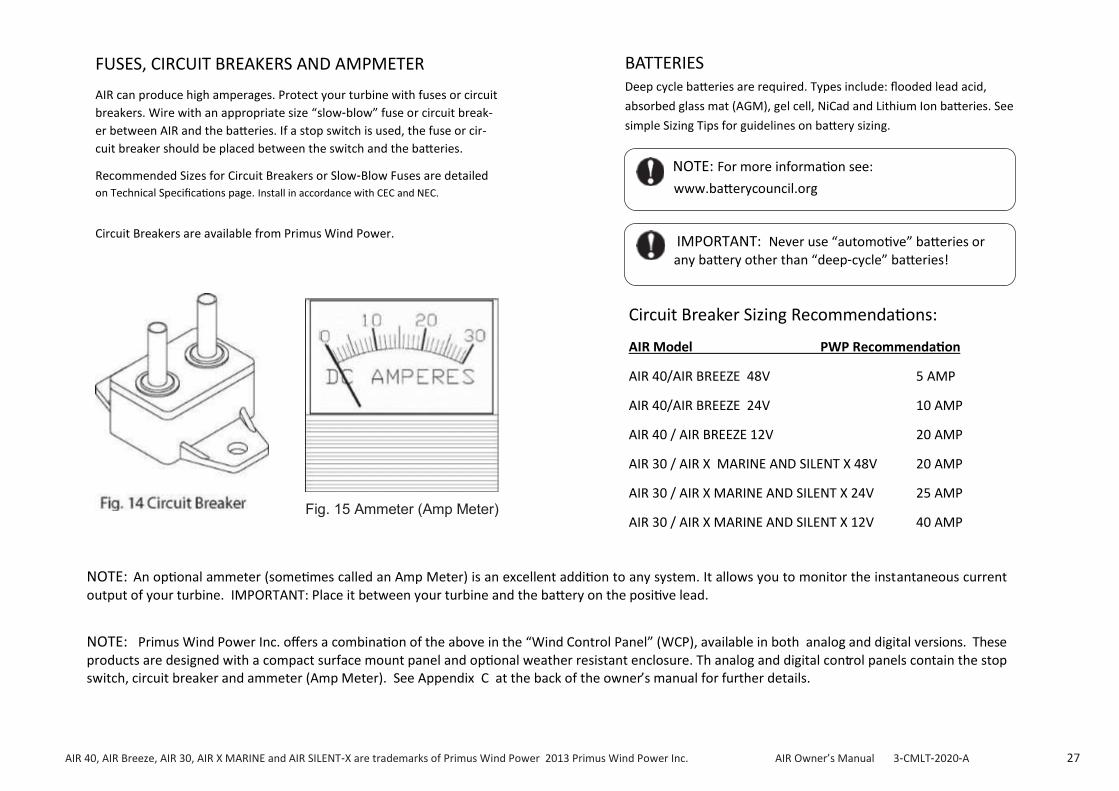
AIR can produce high amperages. Protect your turbine with fuses or circuit
breakers. Wire with an appropriate size “slow-blow” fuse or circuit break-
er between AIR and the batteries. If a stop switch is used, the fuse or cir-
cuit breaker should be placed between the switch and the batteries.
Recommended Sizes for Circuit Breakers or Slow-Blow Fuses are detailed
on Technical Specifications page. Install in accordance with CEC and NEC.
Circuit Breakers are available from Primus Wind Power.
FUSES, CIRCUIT BREAKERS AND AMPMETER BATTERIES Deep cycle batteries are required. Types include: flooded lead acid,
absorbed glass mat (AGM), gel cell, NiCad and Lithium Ion batteries. See
simple Sizing Tips for guidelines on battery sizing.
Fig. 15 Ammeter (Amp Meter)
NOTE: An optional ammeter (sometimes called an Amp Meter) is an excellent addition to any system. It allows you to monitor the instantaneous current output of your turbine. IMPORTANT: Place it between your turbine and the battery on the positive lead.
NOTE: Primus Wind Power Inc. offers a combination of the above in the “Wind Control Panel” (WCP), available in both analog and digital versions. These products are designed with a compact surface mount panel and optional weather resistant enclosure. Th analog and digital control panels contain the stop switch, circuit breaker and ammeter (Amp Meter). See Appendix C at the back of the owner’s manual for further details.
NOTE: For more information see:
www.batterycouncil.org
IMPORTANT: Never use “automotive” batteries or any battery other than “deep-cycle” batteries!
Circuit Breaker Sizing Recommendations:
AIR Model PWP Recommendation
AIR 40/AIR BREEZE 48V 5 AMP
AIR 40/AIR BREEZE 24V 10 AMP
AIR 40 / AIR BREEZE 12V 20 AMP
AIR 30 / AIR X MARINE AND SILENT X 48V 20 AMP
AIR 30 / AIR X MARINE AND SILENT X 24V 25 AMP
AIR 30 / AIR X MARINE AND SILENT X 12V 40 AMP

AIR 40, AIR Breeze, AIR 30, AIR X MARINE and AIR SILENT-X are trademarks of Primus Wind Power 2013 Primus Wind Power Inc. AIR Owner’s Manual 3-CMLT-2020-A 28
TURBINE GROUNDING
Proper grounding of the AIR wind turbine protects people and equipment by eliminating dangerous voltage potentials.
The following section describes tower grounding in detail. To ground the AIR body, connect the ground (green) conductor to the tower ground rod. Alternately the ground (green) conductor may be connected to the negative (black) conductor in which case it will be grounded through the battery bank ground rod. Refer to Figs. 8 -11.
Note that all system grounds should be connected using conductors of the same size as the positive and negative wires.
If you choose to not set up an earth ground system (not required for sys-tems under 50 volts), the green and black conductors MUST be connected to each other or severe damage to the turbine may result and void your warranty.
Primus Wind Power strongly recommends that boat installations be grounded according to American Boat and Yacht Council recommenda-tions. There are special grounding requirements for boats, in particular boats that connect to shore AC power, that MUST be observed or a seri-ous shock hazard may result. Contact the American Boat and Yacht Council at +1 410.990.4460 or at www. abyc.com.
TOWER GROUNDING (Fig. 16)
Every wind turbine and tower should be grounded at the tower base even if the turbine is grounded at the battery bank or service panel by means of the yaw ground lead.
The following sections are a guide and should not be considered compre-hensive. Reference the National Electrical Code (NEC) and local building and zoning regulations for complete requirements. Relevant sections of the National Electrical Code are referenced.
ELECTRODES DRIVEN IN SOIL
Electrodes must be a minimum of 8 ft (2.5 m) in length and free of non- conductive coatings such as paint. Hollow (pipe or conduit) electrodes must not be smaller than trade size 3/4 (metric designator 21) and must be galvanized or otherwise protected from corrosion. Solid rod electrodes must be at least 5/8 inch (16 mm) diameter. Stainless steel rods less than 5/8 inch diameter, nonferrous rods or their equivalent less than 1/2 inch diameter shall be “listed” by an organization having jurisdiction in the area. For example: UL in the USA and CSA in Canada.
Electrodes shall be installed such that 8 ft (2.5 m) is in contact with the soil. They should be driven into undisturbed soil within 1 ft of the tower foun-dation. If rock is encountered the electrode may be driven at an angle
not to exceed 45 degrees from vertical. Some local authorities permit buri-al of the electrode in a trench at least 30 inches (76 cm) deep.
The upper end of the electrode including the grounding conductor should be below grade. If above ground it must be protected from damage.
Bonding the grounding conductor to the electrode and to the tower may be accomplished by exothermic weld or by a “listed” mechanical connect-or. Solder connections are not permitted. Most local authorities require a minimum grounding conductor size of 6 AWG for copper and 4 AWG for aluminum (if aluminum is permitted).
The grounding conductor may be buried directly or contained in conduit. It is important to have no sharp bends to keep its inductance low.
POSITIVE GROUND
The AIR wind turbine has been used and tested successfully in a battery positive “earth ground” configuration. See our FAQ sec-tion on our website at www.primuswindpower.com / FAQ for more details and links.

AIR 40, AIR Breeze, AIR 30, AIR X MARINE and AIR SILENT-X are trademarks of Primus Wind Power 2013 Primus Wind Power Inc. AIR Owner’s Manual 3-CMLT-2020-A 29
WIRE CONNECTIONS TO AIR WIND TURBINE
Secure connections using "split bolt" or solder connectors. Use color coded wires - red for battery positive, black for battery negative, and green for earth ground. Size wiring based on wiring tables provided. Insulate connec-tions with heat shrink tubing or good quality electrical tape. Leave suffi-cient service loop in the wires to accommodate removal of the turbine from the tower.
FINAL CONNECTIONS
Follow system wiring diagram and run wires to disconnect switch, fuse or circuit breaker and ammeter.
Before making battery connections, make sure circuit breakers and stop switch (highly recommended) are in the OFF position. Attach wires to battery; red to positive battery terminal and black to negative battery terminal.
Complete battery connections and switch ON circuit breakers and stop switch. When power is switched on, the turbine LED will illuminate for two seconds, go off for two seconds and illuminate for four seconds. This indi-cates the internal
controller is functioning. The LED remains illuminated if the turbine is charging the battery.
The installation is now complete.
WARNING: Do not connect wires to batteries until all electrical
connections are completed.
WARNING: Reversed wire connections will damage the AIR wind
turbine’s electronics. The polarity of the AIR wind turbine’s wires may be checked by connecting a voltmeter to the wires and spinning the rotor by hand.
2005 NEC Section
Article 250.52, item 5
Article 250.53, item A
Article 250.53, item G
Article 250.64
Article 250.66, item A
Article 270.70
Topic
Tower Grounding
Tower Grounding
Grounding Electrode Installation
Grounding Conductor Routing and Placement
Grounding Conductor Size
Bonding of Grounding Conductor
Cable Clamp
Tower
Grounding Conductor
6 AWG minimum.
Must be secured and
1 ft.
(0.3 m) Grounding Wire Clamp
Grounding Rod
Existing Grade
8 ft.
(2.44m)
Foundation

AIR 40, AIR Breeze, AIR 30, AIR X MARINE and AIR SILENT-X are trademarks of Primus Wind Power 2013 Primus Wind Power Inc. AIR Owner’s Manual 3-CMLT-2020-A 30
AIR WIND TUBINE OPERATION
Operational Summary
AIR converts wind to rotational motion which turns the alternator and pro-duces electrical power. The voltage is regulated for battery charging and integrated controls prevent overcharging of the batteries, allowing the turbine to continue charging until the battery reaches a full state of charge. AIR also uses integrated controls to protect the wind turbine from extreme wind damage.
AIR incorporates a three-phase brushless permanent magnet alternator and microprocessor controlled electronics to optimize its power produc-tion capability. The microprocessor continuously adjusts the loading of the alternator to keep the turbine operating efficiently in most wind regimes. The result is high power production, high blade efficiency, and lower blade noise.
POWER MODE (Charging)
During charging mode, the turbine’s LED is continuously illuminated.
AIR charges batteries when:
• The battery state of charge is above the minimum threshold (e.g. 10.5 volts on a 12 volt system) but below the voltage set point (set at the fac-tory at 14.1V for 12 volt turbines but field changeable via the potenti-ometer)
• Sufficient wind is available
Charging continues until:
• The battery voltage set point has been reached (BATTERY REGULATION FLOAT/STOP)
• The wind is excessively high (OVERSPEED PROTECTION), approximately 16 m/s (35 mph) or greater
• The wind resource decreases such that the wind turbine RPM’s diminish below 420 (LED will turn off)
OVERSPEED PROTECTION: In gusty or sustained high winds greater
than 16 m/s (35 mph), AIR enters overspeed protection where the blades come to a near stop (approximately two revolutions per second). Depend-ing on the code revision level for your turbine, the turbine stops the blades (near stop) until restart is initiated. If the wind is still high or gusty, the cy-cle is repeated until the wind speeds drop below 16 m/s (35 mph). Depend-ing on your code revision, the LED may blink roughly 3 times per second or once every 2 seconds. Contact Primus Wind Power for further LED varia-tions between AIR turbine models/voltages.
Overspeed protection is stressful on the turbine. Primus Wind Power rec-ommends taking measures to protect the turbine in excessively high wind situations.
BRAKE MODE: AIR may be placed in brake mode by directly shorting the
turbine positive and negative wires together or by using a stop switch. The stop switch first disconnects the turbine from the battery and then shorts the positive and negative wires. In very strong winds the blades may rotate slowly even with the switch activated. If a high wind event is in the forecast (gusts greater than 23 m/s (50 mph), it is recommended to consider placing the turbine in brake mode.
AIR 40 Differences: AIR’s integrated controls allow it to generate energy in wind speeds up to 16 m/s (35 mph). Over 16 m/s (35 mph), the turbine blades drop in speed to control heat build-up. Eventually the turbine may shutdown completely to avoid excessive heat build-up in high wind conditions.
AIR 30 Differences: AIR 30 enters overspeed protection in gusty or sus-tained winds over 16 m/s (35 mph) and remains there (as described above) until the wind speeds drop below 16 m/s (35 mph).

AIR 40, AIR Breeze, AIR 30, AIR X MARINE and AIR SILENT-X are trademarks of Primus Wind Power 2013 Primus Wind Power Inc.. AIR Owner’s Manual 3-CMLT-2020-A 31
REGULATION STOP: If the high voltage threshold is confirmed via
REGULATION FLOAT (per the potentiometer/battery regulation set screw setting), the AIR shifts to REGULATION STOP and stops charging the battery; blades will slow dramatically or stop. The turbine remains in regulation until the battery voltage drops below the regulation set point (cut-in voltage). The blades then resume spinning in response to the available wind.
In REGULATION STOP, the turbine’s LED will blink approximately once per second or 3 times per second depending on the code revision level of your turbine.
When the battery voltage drops to the cut-in voltage; which is slightly lower than voltage set point, AIR re -enters REGULATION FLOAT and subsequently POWER MODE. The difference between the two values is termed “hysteresis” and is purposely done to prevent the turbine from bouncing in and out of a single regulation set point.
OPERATION SUMMARY
(REGULATION MODES—continued)
REGULATION FLOAT: When the battery voltage set point has
been reached, the turbine enters a temporary mode called REGULA-TION FLOAT where the voltage is briefly monitored to confirm the high voltage readings. Depending on the code revision, the LED will either blink erratically (quick blinks followed by long blinks) or blink approxi-mately 3 times per second. After a short time, the turbine will shift to REGULATION STOP or back to POWER MODE (depending on the battery voltage readings).
OPEN CIRCUIT CONDITIONS: AIR spins freely if disconnected from an
electrical load (i.e. battery). This results in a cycle of rapid blade speed increas-es followed by rapid braking. This accelerates turbine wear and is non-productive. Primus Wind Power recommends:
• Using a properly installed switch to turn AIR off for short periods of time
• Lowering the turbine completely or securing the blades to prevent rotation if the turbine will be shut down for an extended period of time
BASIC LED (light) FUNCTION:
• LED at “power up” mode will have two slow “BLINKS” (this should be verified prior to raising tower )
• LED “SOLID” indicates “operation or charging mode”
• LED “FAST” blink indicates “overspeed protection or regulation mode”
CONTACT PRIMUS WIND POWER TECH SUPPORT FOR FURTHER ASSISTANCE should none of these LED functions be active!
IMPORTANT: The AIR turbine may not charge if battery open circuit voltage
drops below 10.5V (12V system), 21V (24V) and 42 V (48V system) as the internal
charge control circuit may not recognize that the battery is connected to the turbine
f when connected voltage drops further indicating a totally “dead” battery.

AIR 40, AIR Breeze, AIR 30, AIR X MARINE and AIR SILENT-X are trademarks of Primus Wind Power 2013 Primus Wind Power Inc. AIR Owner’s Manual 3-CMLT-2020-A 32
ADJUSTING REGULATION VOLTAGE
The voltage regulation set point is adjustable using the potentiometer on the
side of the AIR turbine body.
To accurately set the regulation voltage, disconnect the turbine from the
batteries and use an adjustable voltage source (i.e. power supply) and or multi
-meter to apply the desired voltage across the positive and negative turbine
leads. With the target voltage applied, turn the potentiometer fully clockwise,
then slowly turn it counter-clockwise until the LED just illuminates. The regu-
lation set point is now fixed to the voltage applied across the turbine leads.
A second method is to turn the potentiometer fully clockwise. Then monitor
battery voltage while charging and when the desired battery threshold level is
reached, disconnect all current sources (other than the wind turbine) and
loads. This may take a few attempts so that the desired voltage equals the
resting battery voltage. Slowly turn the potentiometer counter clockwise un-
til the LED begins blinking.
Alternatively, the regulation set point voltage may be adjusted using a trial
and error method. Use the accompanying chart as a guide to increase or de-
crease the voltage regulation set point. Monitor the battery voltage over a
period of time and make small adjustments until the regulation set point volt-
age is at the desired level.
* Adjustment ranges are approximate; actual ranges may be greater.
** Turn clockwise to increase voltage, counter-clockwise to decrease voltage.
USING AN ALTERNATE CHARGE CONTROLLER
There are some conditions under which the AIR wind turbine’s internal regu-
lator is not optimal as the primary regulator and instead an external diver-
sion load controller can be substituted. These conditions include:
• Systems where battery temperature varies widely: Battery charge effi-
ciency varies in extreme temperatures. If these conditions exist, use an
external regulator with a temperature compensation sensor to optimize
the charge rate.
• Batteries that are extremely sensitive to charge voltage: Follow the rec-
ommendations of the battery manufacturer. For most batteries the tur-
bine’s internal voltage regulator is adequate. However, the most con-
servative approach is the use of a diversion load controller due to 3 stage
charging.
• Multiple turbine installations with a bus system will typically function
best using a single voltage regulator (i.e. diversion load controller) close
to the battery bank. This is particularly true if the wire lengths connecting
each turbine to the bus vary by distance or wire gauge. Without a diver-
sion load controller, multiple turbines may shift into battery regulation at
slightly different times due to line loss differences, etc.
CAUTION: Increasing the voltage regulation set point above the ini-tial factory setting will NOT increase the power output of the AIR wind turbine. This adjustment changes the voltage at which the turbine stops charging the batteries. By set-ting the voltage too high you may increase the probability of overcharging and damaging the batteries.
System Voltage
Factory Set
Point
Voltage Regulation Set-Point
Adjustment Range*
Voltage Change due to 1/8 Turn of Potentiometer**
12 Volt 14.1 Volts 13 – 17 Volts 0.5 Volts
24 Volt 28.2 Volts 26 – 34 Volts 1.0 Volts
48 Volt 56.4 Volts 52 – 68 Volts 2.2 Volts
AIR 40, AIR Breeze, AIR 30, AIR X MARINE and AIR SILENT-X are trademarks of Primus Wind Power 2013 Primus Wind Power Inc. AIR Owner’s Manual 3-CMLT-2020-A 33
The turbine’s internal voltage regulator cannot be completely
turned off. However, by setting the voltage regulation set-point to
its highest value the internal regulator is virtually nullified. If an
external charge controller is utilized, it must be a diversion style
regulator which diverts the excess power to a resistive load.
IMPORTANT: Do not use a pulse width modulated (PWM), maxi-
mum power point tracking (MPPT) or shunt style controller (other
than as diversion load controller). The AIR wind turbine is not de-
signed to work with these types of controllers where the controller
is wired between the wind turbine and the battery bank. Addition-
ally, most controllers designed to work with solar panels are not
suitable for use with the AIR wind turbine. These controllers
“disconnect” the solar panels – or in this case the AIR - from the
battery bank when the batteries are charged, allowing the turbine
to spin free, which is not recommended.
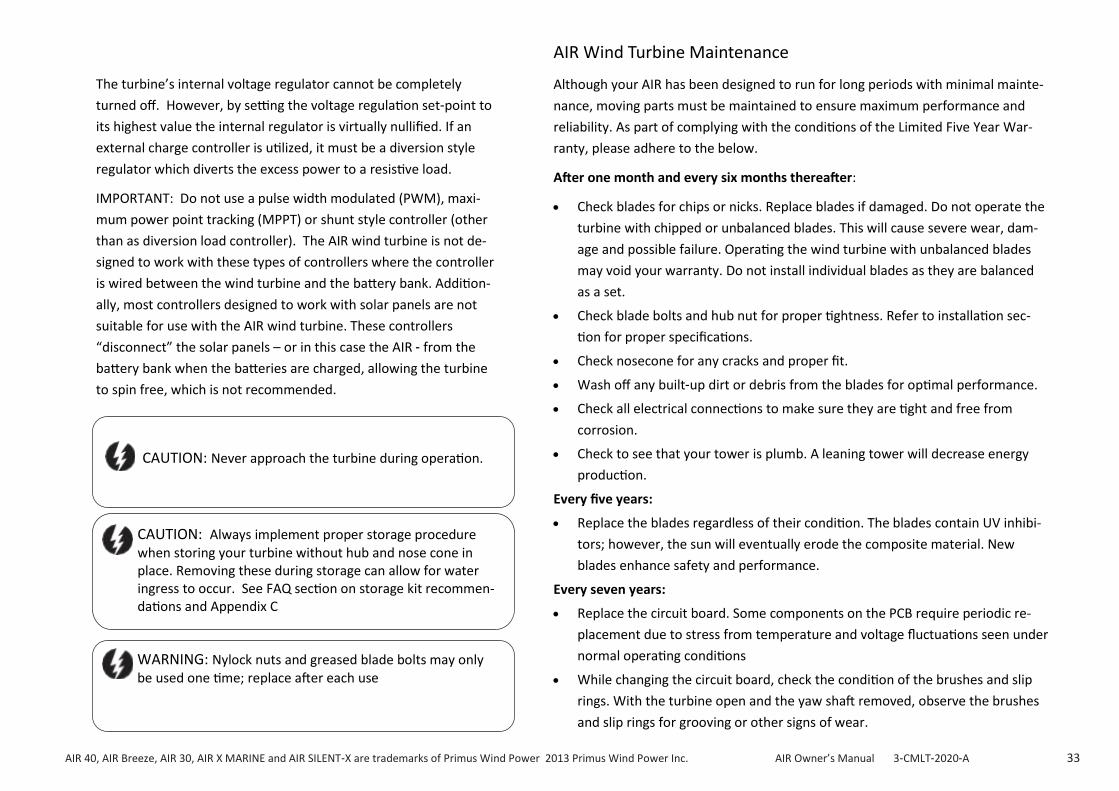
AIR Wind Turbine Maintenance
Although your AIR has been designed to run for long periods with minimal mainte-
nance, moving parts must be maintained to ensure maximum performance and
reliability. As part of complying with the conditions of the Limited Five Year War-
ranty, please adhere to the below.
After one month and every six months thereafter:
• Check blades for chips or nicks. Replace blades if damaged. Do not operate the
turbine with chipped or unbalanced blades. This will cause severe wear, dam-
age and possible failure. Operating the wind turbine with unbalanced blades
may void your warranty. Do not install individual blades as they are balanced
as a set.
• Check blade bolts and hub nut for proper tightness. Refer to installation sec-
tion for proper specifications.
• Check nosecone for any cracks and proper fit.
• Wash off any built-up dirt or debris from the blades for optimal performance.
• Check all electrical connections to make sure they are tight and free from
corrosion.
• Check to see that your tower is plumb. A leaning tower will decrease energy
production.
Every five years:
• Replace the blades regardless of their condition. The blades contain UV inhibi-
tors; however, the sun will eventually erode the composite material. New
blades enhance safety and performance.
Every seven years:
• Replace the circuit board. Some components on the PCB require periodic re-
placement due to stress from temperature and voltage fluctuations seen under
normal operating conditions
• While changing the circuit board, check the condition of the brushes and slip
rings. With the turbine open and the yaw shaft removed, observe the brushes
and slip rings for grooving or other signs of wear.
CAUTION: Always implement proper storage procedure when storing your turbine without hub and nose cone in place. Removing these during storage can allow for water ingress to occur. See FAQ section on storage kit recommen-dations and Appendix C
CAUTION: Never approach the turbine during operation.
WARNING: Nylock nuts and greased blade bolts may only be used one time; replace after each use
AIR 40, AIR Breeze, AIR 30, AIR X MARINE and AIR SILENT-X are trademarks of Primus Wind Power 2013 Primus Wind Power Inc. AIR Owner’s Manual 3-CMLT-2020-A 34
AIR WIND TURBINE TROUBLE SHOOTING
ON TOWER TROUBLE SHOOTING:
With the turbine on the tower, observe the behavior of the turbine dur-ing different states of the stop switch. On a moderate to strong wind day (winds 15 mph or greater):
1.) Place the stop switch in the STOP position (or RED and BLACK wires disconnected from the battery and crossed), the turbine should spin ap-proximately 2 revolutions per second in moderate to high winds. If the turbine spins at a significantly higher rate than that, it is likely an electri-cal connection is not secure or is corroded.
2.) Place the stop switch in the OPEN position (or wires disconnected from the battery), the turbine should repeatedly start up and shut down roughly every 30 seconds. If the turbine does this with the stop switch in any position, the turbine is not likely electrically connected to the battery bank.
3.) Place the stop switch in the RUN position (or breaker turned on), the LED should blink twice (the duration of the blinks is dependent on the code revision for that turbine). The turbine will begin spinning up with sufficient wind and the LED should come on solid (and stay on solid) if RPM are above 450 and current output should begin. If the turbine does not spin up and the LED is blinking, it could be that the turbine is in battery regulation (i.e. battery voltage is higher than the potentiometer set point, in which case the turbine is behaving appropriately).
NOTE: If the turbine spins roughly two revolutions per second in any position of the stop switch (i.e. no change in behavior between different positions of the stop switch), the circuit card (or possibly the stator) is likely compromised.
4.) With the turbine spinning and the LED on solid, monitor current output (or battery voltage) as the wind resource fluctuates. If monitoring battery voltage, disconnect all loads (if practical) to insure the turbine is charging the battery. If the turbine shuts down (i.e. blades come to a near stop) at times you would not expect, note the LED activity during those times. Also note if the shut-down duration is consistent.
BENCH TESTS:
If the turbine fails the on tower test (s), the next step is the bench tests below. The bench tests remove the balance of system wiring as a variable.
TEST 1 Stand Alone Test
1.) Remove the blade/hub assembly from the turbine and place in a safe location. Replace the rotor hub nut on the rotor shaft.
2.) With the Air turbine completely disconnected and removed from the battery or any other connection, Attempt to quickly spin the rotor shaft with your fingers while connecting and disconnecting the red and black wires (turbine must not be connected to batteries). A second person may be helpful to perform this test.
3.) With the red and black wires connected to each other, the shaft should be more difficult to turn. With the yaw wires disconnected it should spin freely. Spinning the shaft quickly makes this difference easier to detect. If these conditions do not exist, contact your turbine dealer or Primus Wind Power.
IMPORTANT: it is recommended to “Power Cycle” your turbine as a first step in troubleshooting process. Power your turbine OFF (wait 5 min), then ON, look for two LED blinks. This process will reset the electronic control circuit and verify the turbine is receiving power.

AIR 40, AIR Breeze, AIR 30, AIR X MARINE and AIR SILENT-X are trademarks of Primus Wind Power 2013 Primus Wind Power Inc.. AIR Owner’s Manual 3-CMLT-2020-A 35
BENCH TEST (continued):
TEST 2 Power Up Test
1.) Remove blade/hub assembly from turbine and place in a safe location.
2.) Connect the turbine power wires to the appropriate terminals on your battery: RED= Positive, BLACK = Negative.
3.) Each time the AIR wind turbine is connected to a battery, the LED will blink twice. The Air 40/Air Breeze LED will come on for two seconds, go off for two seconds and come back on for four seconds to indicate that the controller is running properly. The Air 30/Air X and older Air Breeze tur-bines, depending on the code revision, will have the same blink cycle as the Air 40/Air Breeze or will have a shorter set of blinks (roughly ½ second per blink). You may need to wait 10 seconds between iterations of this test in order to let the turbine discharge completely. The turbine is in Brake Mode while initializing the controller. If the LED does not blink when the AIR wind turbine is connected to a battery, you should contact your turbine dealer or Primus Wind Power.
TEST 3 Spin Test
1.) Remove blade/hub assembly from turbine and place in a safe location
2.) With the AIR wind turbine connected to your battery bank, use an electric drill to spin the rotor shaft while observing the LED. A short length cut from the 5/16 inch hex key wrench can serve as a drive if necessary.
3.) Below 400 RPM, the rotor should spin freely and the LED should remain off.
4.) At 460 RPM and above, the AIR wind turbine should be charging the battery. At this point, current should be present and can be measured using an appropriate meter, measure in milli-amps in addition to volts. (note: only small amounts of current will be present until higher RPM’s (approximately 700 RPM) are attained). There should be resistance on the rotor shaft and the LED should turn on. If the shaft is cogging (intermittent resistance) or the turbine is consuming power, contact your turbine deal-er or Primus Wind Power. Be sure your battery voltage is not high enough to activate the regulation mode during this test (LED will blink).
TEST 4 Stator Test
1.) Remove the face assembly by removing the 3 face bolts. Noting which wires go where for reassembly, remove the stator wires from the circuit card. From left to right, the wire sequence should be 2-3-1.
2.) With none of the 3 stator wires touching one another, spin the rotor quickly with your hand. It should spin easily. Repeat this touching wires 1 and 2 together. There should be a noticeable difference in rotational re-sistance. Repeat with wires 2 and 3 and then 1 and 3. These 3 scenarios should have the same rotational resistance. With all 3 wires touching, the rotational resistance should be increased.
3.) If possible, take pictures of the inside of the turbine including the slip rings and the circuit card/brushes from different perspectives to see around the yaw assembly. Note any other observations of damage or wear.
NOTE: If the turbine failed one or more of the bench tests, contact Primus Wind Power technical support at 303-242-5820 x 3 or [email protected] with the results of your
on tower and bench tests (as well as any other behavior details). Please include the serial number, product number, and voltage with all correspondence. Technical support may ask to
investigate further by opening the turbine and testing the stator (per below). Primus offers in house repair services as well as parts for field repair.

AIR 40, AIR Breeze, AIR 30, AIR X MARINE and AIR SILENT-X are trademarks of Primus Wind Power 2013 Primus Wind Power Inc. AIR Owner’s Manual 3-CMLT-2020-A 36
Exploded Views & Parts List
AIR 40 and AIR BREEZE

AIR 40, AIR Breeze, AIR 30, AIR X MARINE and AIR SILENT-X are trademarks of Primus Wind Power 2013 Primus Wind Power Inc. AIR Owner’s Manual 3-CMLT-2020-A 37
Exploded View Parts List—Numeric Designation AIR 40 and AIR BREEZE
ITEM NO. DESCRIPTION PART NUMBER QTY.
1 NOSE CONE 3-CMBP-2015-01 (AIR 40) 1
3-CMBP-2015-02 (AIR Breeze) 1
2 JAM NUT 5/8-18 - SS 3-HDNT-912 1
3 SCREW - SOCKET HEAD - 1/4-20 X 1-3/8 - SS 3-HDBT-1024-007 3
4 WASHER - FLAT -1/4"- SS 3-HDWA-919 3
5 MACHINED - HUB - AIR 3-CMBP-2016-01 (AIR 40) 1
3-CMBP-2016-02 (AIR Breeze) 1
6 BLADE - BLACK 3-CMBP-2017-03 3
7 NUT - NYLOCK - SAE - SS - 1/4"-20 3-HDNT-102-10 3
8 SCREW - SOCKET HEAD - 10-24 X 1-1/2" 3-HDBT-1000-577 3
9 MACHINED - FACE - AIR 3-CMBP-1003-01 1
10 SNAP RING - 44MM INTERNAL 3-CAOT-1005 1
11 BEARING - 6203-RLBZD - SEALED/SHIELDED 3-CABR-1002 1
12 WASHER - WAVE SPRING 3-CAOT-1012 2
13 SPACER - BEARING 3-CAOT-1010 1
14 BEARING - 6203-ZZ - SHIELDED 3-CABR-1001 1
15 ISOLATOR - STATOR 3-CMBP-1341 1
STATOR - 16 AWG 17 TURNS 3-CMBP-1019-02
16 STATOR - 18 AWG 34 TURNS 3-CMBP-1019-03 1
STATOR - 21 AWG 60 TURNS 3-CMBP-1019-05
17 ROTOR - HP 3-CMBP-1313 1
18 SCREW - TAPTITE - 8/32 X 1" 3-HDBT-9000 2
CIRCUIT & RECTIFIER ASSEMBLY - 12V 3-CMBP-1021-12
19 CIRCUIT & RECTIFIER ASSEMBLY - 24V 3-CMBP-1021-24 1
CIRCUIT & RECTIFIER ASSEMBLY - 48V 3-CMBP-1021-48
20 WIRE HARNESS - POTENTIOMETER 3-CMBP-1033-02 1
21 O-RING 3-CAOT-1002 1
22 MACHINED - BODY - AIR 3-CMBP-1000-01 1
23 BEARING - 6007 2RS 3-CABR-1000 1
24 SNAP RING - INTERNAL - 69MM - ZINC 3-CAOT-1067 (AIR 40) 1
3-CMBP-1011 (AIR Breeze) 1
25 SNAP RING - 32MM STAINLESS STEEL 3-CAOT-1219 1
26 YAW ASSEMBLY 3-ARYW-101-01 (AIR 40) 1
3-ARYW-101-02 (AIR Breeze) 1

AIR 40, AIR Breeze, AIR 30, AIR X MARINE and AIR SILENT-X are trademarks of Primus Wind Power 2013 Primus Wind Power Inc. AIR Owner’s Manual 3-CMLT-2020-A 38
AIR 40 AND AIR BREEZE SPARE PARTS LIST (not all parts are available individually – see kits)
PART NUMBER
KIT DESCRIPTION
EXPLOADED VIEW 3-CMBP-2015-01 NOSE CONE AIR 30 - LAND (1)
3-CMBP-2015-02 NOSE CONE AIR X / SILENT X - MARINE (1)
2-ARBR-101 AIR 40 AND AIR BREEZE BLADE SET AND HARDWARE (2,3,4,6 & 7
3-CMBP-1023-06 AIR 40 AND AIR BREEZE HARDWARE KIT (2,3 & 6)
3-HDNT-912 AIR – JAM NUT – NOT SOLD INDIVIDUALLY (2)
3-CMBP-2016-01 AIR 40 HUB – LAND (5)
3-CMBP-2016-02 AIR X BREEZE MARINE HUB – MARINE ANODIZED (5)
3-CMBP-1171-01 AIR 40 FACE BOLT KIT (8)
2-ARYF-100-02 AIR LAND AND MARINE FACE AND YAW BEARING KIT (10,11,12,13,14,21 & 23,24,25)
3-CMBP-1003-01 AIR FACE ASSEMBLY (9)
3-CMBP-1019-02 AIR 40 AND AIR BREEZE 12V STATOR (16)
3-CMBP-1019-03 AIR 40 AND AIR BREEZE 24V STATOR (16)
3-CMBP-1019-05 AIR 40 AND AIR BREEZE 48V STATOR (16)
3-CMBP-1313 AIR 40 AND AIR BREEZE – ROTOR SHAFT (17)
2-ARCT-103-01 AIR 40 AND AIR BREEZE CIRCUIT KIT 12V+BOLTS (18,19,20 & 21)
2-ARCT-103-02 AIR 40 AND AIR BREEZE CIRCUIT KIT 24V+BOLTS (17,18,19, 20 & 21)
2-ARCT-103-03 AIR 40 AND AIR BREEZE CIRCUIT KIT 48V+BOLTS (17,18,19, 20 & 21)
3-CMBP-1033-02 AIR POTENTIOMETER – NOT SOLD INDIVIDUALLY (19)
3-CAOT-1002 VITON O-RING – NOT SOLD INDIVIDUALLY (21)
3-CMBP-1000-01 AIR 40 LAND CASTING - CONTACT MFG. (22)
3-CMBP-1000-04 AIR BREEZE CASTING – CONTACT MFG. (22)
2-ARYF-100-02 AIR 40 AND AIR BREEZE FACE AND YAW BEARING KIT (10,11,12,13,14, 21 & 23,24,25)
2-ARYW-101-01 AIR 40 YAW SHAFT ASSEMBLY (26)
2-ARYW-101-02 AIR BREEZE YAW SHAFT ASSEMBLY (26)

AIR 40, AIR Breeze, AIR 30, AIR X MARINE and AIR SILENT-X are trademarks of Primus Wind Power 2013 Primus Wind Power Inc. AIR Owner’s Manual 3-CMLT-2020-A 39
Exploded Views & Parts List
AIR 30, AIR X AND AIR SILENT X

AIR 40, AIR Breeze, AIR 30, AIR X MARINE and AIR SILENT-X are trademarks of Primus Wind Power 2013 Primus Wind Power Inc. AIR Owner’s Manual 3-CMLT-2020-A 40
Exploded View Parts List - Numeric Designation AIR 30, AIR X and AIR SILENT X
ITEM NO. DESCRIPTION PART NUMBER QTY.
1 NOSE CONE - GRAY 3-CMBP-1007-01 1
2 JAM NUT 5/8-18 - SS 3-HDNT-912 1
3 SCREW - SOCKET HEAD - 1/4-20 X 7/8" - SS 3-HDBT-1000-04 6
4 MACHINED - HUB 3-CMBP-1005-01 1
5 BLADE 3-CMBP-1008 3
6 NUT - NYLOCK - SAE - SS - 1/4"-20 3-HDNT-102-10 6
7 SCREW - SOCKET HEAD - 10-24 X 1-1/2" 3-HDBT-1000-577 3
8 MACHINED - FACE - AIR 3-CMBP-1003-0 1 1
9 SNAP RING - 44MM INTERNAL 3-CAOT-1005 1
10 BEARING - 6203-RLBZD - SEALED/SHIELDED 3-CABR-1002 1
11 WASHER - WAVE SPRING 3-CAOT-1012 2
12 WASHER - BEARING 3-CAOT-1227 2
13 BEARING - 6203-ZZ - SHIELDED 3-CABR-1001 1
14 ISOLATOR - STATOR 3-CMBP-1341 1
15
STATOR - 16 AWG 10 TURNS 3-CMBP-1019-01
1 STATOR - 16 AWG 17 TURNS 3-CMBP-1019-02
STATOR - 18 AWG 34 TURNS 3-CMBP-1019-03
16 ROTOR - HP 3-CMBP-1313 1
17 SCREW - TAPTITE - 8/32 X 1" 3-HDBT-9000 2
18
CIRCUIT & RECTIFIER ASSEMBLY - 12V 3-CMBP-1021-12
1 CIRCUIT & RECTIFIER ASSEMBLY - 24V 3-CMBP-1021-24
CIRCUIT & RECTIFIER ASSEMBLY - 48V 3-CMBP-1021-48
19 WIRE HARNESS - POTENTIOMETER 3-CMBP-1033-01 1
20 O-RING 3-CAOT-1002 1
21 MACHINED - BODY - AIR 3-CMBP-1000-01 1
22 BEARING - 6007 2RS 3-CABR-1000 1
23 SNAP RING - INTERNAL - 69MM - ZINC 3-CAOT-1067 1
24 SNAP RING - 32MM STAINLESS STEEL 3-CAOT-1219 1
25 YAW ASSEMBLY 2-ARYW-101-01 1

AIR 40, AIR Breeze, AIR 30, AIR X MARINE and AIR SILENT-X are trademarks of Primus Wind Power 2013 Primus Wind Power Inc.. AIR Owner’s Manual 3-CMLT-2020-A 41
3-CMBP-1007-01 NOSE CONE AIR 30 - LAND (1)
3-CMBP-1007-02 NOSE CONE AIR X / SILENT X - MARINE (1)
2-ARBL-101-01 AIR 30 AND AIR X MARINE BLADE SET AND HARDWARE (2,3,5 & 6)
2-ARBL-102-01 AIR SILENT X BLADE SET AND HARDWARE KIT (2,3,5 & 6)
3-CMBP-1023-01 AIR 30, AIR X MARINE /SILENT X HARDWARE KIT (2,3 & 6)
3-HDNT-912 AIR – JAM NUT – NOT SOLD INDIVIDUALLY (2)
3-CMBP-1005-01 AIR 30 HUB – LAND (4)
3-CMBP-1005-02 AIR X MARINE / SILENT X HUB – MARINE ANODIZED (4)
3-CMBP-1171-01 AIR 30 FACE BOLT KIT (7)
2-ARYF-100-02 AIR LAND AND MARINE FACE AND YAW BEARING KIT (9,10,11,12,13 & 22,23,24)
3-CMBP-1003-01 AIR FACE ASSEMBLY (8)
3-CMBP-1019-01 AIR 30, AIR X MARINE / SILENT X 12V STATOR (15)
3-CMBP-1019-02 AIR 30, AIR X MARINE / SILENT X 24V STATOR (15)
3-CMBP-1019-03 AIR 30, AIR X MARINE /SILENT X 48V STATOR (15)
3-CMBP-1313 AIR 30, AIR X MARINE/ SILENT X – ROTOR SHAFT (16)
2-ARCT-101-03 AIR 30, AIR X MARINE / SILENT X CIRCUIT KIT 12V+BOLTS (17,18,19 & 20)
2-ARCT-101-05 AIR 30, AIR X MARINE / SILENT X CIRCUIT KIT 24V+BOLTS (17,18,19 & 20)
2-ARCT-101-06 AIR 30, AIR X MARIINE / SILENT X CIRCUIT KIT 48V+BOLTS (17,18,19 & 20)
3-CMBP-1033-02 AIR POTENTIOMETER – NOT SOLD INDIVIDUALLY (19)
3-CAOT-1002 VITON O-RING – NOT SOLD INDIVIDUALLY (20)
3-CMBP-1000-01 AIR 30 LAND CASTING (ONLY) - CONTACT MFG. (21)
3-CMBP-1000-04 AIR X MARINE / SILENT X CASTING (ONLY)– CONTACT MFG. (21)
2-ARYF-100-02 AIR 30 AND AIR X MARINE / SILENT X FACE AND YAW BEARING KIT (9,10,11,12,13 & 22,23,24)
2-ARYW-101-01 AIR 30 YAW SHAFT ASSEMBLY (26)
2-ARYW-101-02 AIR X MARINE/ SILENT X YAW SHAFT ASSEMBLY (26)
AIR 30, AIR X MARINE AND SILENT- X MARINE SPARE PARTS LIST (not all parts are available individually – see kits)

AIR 40, AIR Breeze, AIR 30, AIR X MARINE and AIR SILENT-X are trademarks of Primus Wind Power 2013 Primus Wind Power Inc. AIR Owner’s Manual 3-CMLT-2020-A 42
AIR WIND TURBINE FIVE YEAR (5 YR.) - LIMITED WARRANTY
Length of Limited Warranty and What is Covered
Primus Wind Power Inc. ("Primus Wind Power") warrants to the original end-user purchaser (the
"Customer") of the AIR Wind Turbine (the "Wind Turbine") that the Wind Turbine will be free from defects
in factory supplied materials and factory workmanship for a period of five (5) years from the earliest to
occur of the following dates: (i) date of the completed installation of the Wind Turbine if installed by an
authorized Wind Power installer, or (ii) ninety (90) days after the date the Customer purchases the Wind
Turbine (the "Warranty Period").
Purchase of the Wind Turbine constitutes acceptance of the terms and conditions of this Limited Warran-
ty. This Limited Warranty extends only to the Customer and may not be transferred if the Wind Turbine is
sold.
The Customer's sole and exclusive remedy and the entire liability of Primus Wind Power, its dealers, sup-
pliers and affiliates under this Limited Warranty is, at Primus Wind Power's sole option, either (i) to repair
free of charge the defective part or Wind Turbine, or (ii) exchange free of charge the defective part or
Wind Turbine with a new or remanufactured part or Wind Turbine that is new or equivalent to new in
performance and reliability and is at least functionally equivalent to the original part or Wind Turbine.
Should the product prove to be irreparable, Primus Wind Power reserves the right to substitute an equiva-
lent product if available. Repaired, exchanged, or substituted Wind Turbine parts or products pursuant to
this Limited Warranty will be warranted for the remainder of the Warranty Period subject to the re-
strictions, limitations, and exclusions of this Limited Warranty.
Restrictions on Limited Warranty
This Limited Warranty applies to the Wind Turbine only if the Customer follows the installation, mainte-
nance, and operation procedures outlined in the Wind Turbine's Owner's Manual. If Primus Wind Power
determines that the claimed problem with the Wind Turbine is not due to a defect in Primus Wind Power's
workmanship or materials, then the party requesting the warranty service shall be responsible for the
costs of all necessary repairs performed and expenses incurred by Primus Wind Power.
How to Register The Wind Turbine and Warranty Procedures
Primus Wind Power strongly recommends registration of the Wind Turbine with the warranty registration
materials provided with the product. The Customer is encouraged to return the warranty registration
document included with this Limited Warranty within sixty (60) days of the start of the Warranty Period. A
Customer may also visit http:// www.primuswindpower.com/maintenance-service/warranty1 / to register
the Wind Turbine online. While submission of the warranty registration document does not reduce a
Customer's eligibility to receive warranty service, the Customer will be required to provide proof of own-
ership and original purchase (including a copy of the original receipt) and date of purchase or installation
satisfactory to Primus Wind Power prior to receiving warranty services.
All Customer warranty claims must be received by Primus Wind Power during the Warranty Period. For
any problems with a Wind Turbine, please contact an Authorized Service Dealer ("ASD") or Primus
Wind Power directly. To find a Primus Wind Power ASD close by or to report a claim to technical sup-
port, call Primus Wind Power at (303) 242-5820 Monday-Friday 8:00AM - 5:00 PM Mountain Standard
Time. The ASD may be able to provide a possible solution and can also start the warranty claims pro-
cess.
A warranty claim notification must include a description of the defect, the serial number of the Wind
Turbine at issue, the original purchase date, and the name, address, and telephone number of the
Customer requesting warranty service under this Limited Warranty. All claims for defect shall be
deemed waived unless made in writing and delivered to Primus Wind Power during the Warranty
Period and not later than thirty (30) days after discovery of the defect. Please retain all information
and documents until the warranty issues are resolved.
After Primus Wind Power is notified, Primus Wind Power representatives will make all reasonable
efforts via phone and email to ascertain the nature of the problem to determine whether any part or
the Wind Turbine is defective for purposes of coverage under this Limited Warranty. Other than nor-
mal communication carrier charges, there is no charge for such diagnosis. Any repair or replacement
will be provided only after Primus Wind Power's diagnosis and its agreement regarding the defective
condition. Certain diagnostic checks may be required to be performed by the Customer or designee at
Primus Wind Power's representatives' request.
If Primus Wind Power representatives determine that the Wind Turbine requires service and that
Customer's service request constitutes a valid claim under this Limited Warranty, Primus Wind Power
will provide warranty service, at Primus Wind Power's sole option, either (i) through an ASD, with
service to be performed at the servicer's location; (ii) by sending replacement Wind Turbine or parts to
the Customer or (iii) by providing the Customer with a Return Merchandise Authorization ("RMA")
number to authorize the Customer to ship the defective Wind Turbine or Wind Turbine parts to Primus
Wind Power for service.
Any Wind Turbine/part(s)) requiring warranty repair shall be transported to Primus Wind Power at the
Customer's expense and risk, including but not limited to proper packaging of the Wind Turbine/part
(s). Primus Wind Power will return to sender any Wind Turbine and/or part(s) that do not have a valid
RMA number. Primus Wind Power will use all reasonable efforts to repair/replace the defective Wind
Turbine and/or part(s). Repaired or replaced Wind Turbines and replacement parts will be delivered to
the Customer at Primus Wind Power's expense.
(continued)

AIR 40, AIR Breeze, AIR 30, AIR X MARINE and AIR SILENT-X are trademarks of Primus Wind Power 2013 Primus Wind Power Inc. AIR Owner’s Manual 3-CMLT-2020-A 43
AIR Wind Turbine Five Year (5 Yr.) - Limited Warranty (continued)
If a warranty claim is invalid for any reason, the Customer may be charged at Primus Wind Power's and/
or the ASD's then current rate for repair services performed. In such event, the Customer will be in-
formed of the repair charges for prior approval, and, upon approval, will be charged for the approved
repairs and return freight. If the Customer refuses to approve repair charges, return freight charges
may apply. When a Wind Turbine part is replaced for a new or remanufactured part, such new or re-
manufactured part becomes Customer's property and the replaced part becomes Primus Wind Power's
property. Customer property remaining at Primus Wind Power's repair facilities for more than ninety
(90) days without required Customer approval of return freight charges, becomes the property of Pri-
mus Wind Power.
Exclusions and Limitations
Problems with Wind Turbines can be due to improper installation, use, maintenance, or repairs, non-
Primus Wind Power additions or modifications, or other problems not due to defects in Primus Wind
Power's workmanship or materials. Primus Wind Power does not warrant that the operation of the
Wind Turbine will be uninterrupted, nor does this Limited Warranty guarantee specific performance or
energy production under any conditions. This Limited Warranty does not apply to claims arising from
installation of the Wind Turbine at improper or deficient site locations as described in the Wind Tur-
bine's Owner's Manual or to installation that was not performed by an authorized Wind Power installer.
This Limited Warranty does not cover any part that was not manufactured by Primus Wind Power, nor
does it cover the costs of any repairs or adjustments to a Wind Turbine that might be needed because
of the use of non-Primus Wind Power parts, components, equipment, or materials.
This Limited Warranty also does not cover:
(i) consumable parts and the costs of normal maintenance, parts, and service not related to a warranty
claim;
(ii) equipment that was not new at the time of purchase;
(iii) damage due to normal wear and tear;
(iv) cosmetic damage, including scratches or dents unless such damage compromises the product's
function;
(v) damage caused by abnormal electrical stress, including, but not limited to overload, surges, use with
any unsuitable power source, voltage irregularities or utility system failures that enter the Wind Tur-
bine through the output side;
(vi) damage caused by acts of God (including flood, fire, earthquake, lightning, hail damage, flying de-
bris, wind speeds in excess of 120 mph, tornadoes, hurricanes or other cyclonic windstorms), abnormal
physical stress, abnormal thermal stress, misuse, negligence, accident, abuse, or vandalism
vii) damage due to a failure to service and maintain, and/or operate the Wind Turbine in accordance with
its Owner's Manual or other instructions provided by Primus Wind Power;
(viii) a Wind Turbine or any of its parts that has been altered or modified without the prior written per-
mission of Primus Wind Power;
(ix) any Wind Turbine part on which the serial number has been removed or defaced; (x) damage or loss
to any items or products not manufactured by Primus Wind Power that are connected to, powered by, or
otherwise attached to, the Wind Turbine;
(xi) damage sustained during unloading, shipment, for transit from Primus Wind Power or an ASD to the
Customer location shown on the purchase order (or other delivery point designated by Customer) or
during installation;
(xii) any expenses incurred from travel to and from the repair location, troubleshooting, diagnostic and
repair services, equipment expenses;
(xiii) damage due to improper installation of the Wind Turbine that is not in accordance with the Owner's
manual, or
(xiv) use of the Wind Turbine in wind regimes with an annual average of 18 mph (8 m/s) or greater.
(XV) Storage of the turbine which is exposed to the elements without the hub and nose cone in place is
not recommended and may void your warranty.
REPLACEMENT PARTS LIMITED WARRANTY
Primus Wind Power offers replacement parts for all Wind Turbine products that can be purchased direct-
ly from the manufacturer and or dealer/ distributors.
Replacement parts such as circuit kits, yaw assembly, bearings, blades etc. have a Ninety (90) Day Limited
Parts Warranty (this limited parts warranty does not apply to misused and or incorrect handling of com-
ponents during repair or exchange). The Ninety (90) Day Limited Parts Warranty is for a period of ninety
(90) days beginning on the date of invoice and, to the extent applicable, is subject to the exclusions,
limitations, and procedures set forth in this Limited Warranty. Notice of a claim under this Warranty must
be received by Primus Wind Power or an ASD within the ninety-day limited warranty period.
IN-HOUSE REPAIR SERVICE LIMITED WARRANTY
Primus Wind Power provides in-house repair service for regular, non-warranty repairs for the Wind Tur-
bine product via our PWP trained technical repair team and or via an ASD.
(continued)

AIR 40, AIR Breeze, AIR 30, AIR X MARINE and AIR SILENT-X are trademarks of Primus Wind Power 2013 Primus Wind Power Inc. AIR Owner’s Manual 3-CMLT-2020-A 44
AIR Wind Turbine Five Year (5 Yr.) - Limited Warranty (continued)
The In-House Repair Service Limited Warranty provides a six-month limited warranty on parts and
labor quoted within the repair (warranty is only applicable with a full pre-qualification of repair needs,
parts required and labor outlined within a company quote process). The In-House Repair Service Lim-
ited Warranty does not include or cover other non-authorized repairs by third party repair services.
The six-month In- House Repair Service Limited Warranty starts from invoice date (completion of re-
pair). Notice of a claim under this In-House Repair Service Limited Warranty must be received by Pri-
mus Wind Power or an ASD within the six-month limited warranty period. To the extent applicable, the
In-House Repair Service Limited Warranty is subject to the exclusions, limitations, and procedures of
this Limited Warranty.
Disclaimer of Warranty
These Limited Warranties grant specific legal rights, and there may exist other rights that vary from
state to state.
TO THE FULL EXTENT PERMITTED BY APPLICABLE LAW, THE EXPRESS LIMITED WARRANTIES AND THE
REMEDIES SET FORTH HEREIN ARE EXCLUSIVE AND IN LIEU OF ALL OTHER WARRANTIES, REMEDIES
AND CONDITIONS, WHETHER ORAL, WRITTEN, STATUTORY, EXPRESS OR IMPLIED. AS PERMITTED BY
APPLICABLE LAW, PRIMUS WIND POWER DISCLAIMS ANY AND ALL STATUTORY OR IMPLIED WARRAN-
TIES, INCLUDING, WITHOUT LIMITATION, THE IMPLIED WARRANTIES OF FITNESS FOR A PARTICULAR
PURPOSE, MERCHANTABILITY, NON-INFRINGEMENT AND WARRANTIES AGAINST HIDDEN OR LATENT
DEFECTS AND ALL SIMILAR WARRANTIES ESTABLISHED UNDER APPLICABLE LAWS. NO OTHER WAR-
RANTY, EXPRESS OR IMPLIED, WHETHER OR NOT SIMILAR IN NATURE TO ANY OTHER WARRANTY
PROVIDED HEREIN, SHALL EXIST WITH RESPECT TO THE PRODUCT SOLD UNDER THE PROVISION OF
THESE TERMS AND CONDITIONS. TO THE FULL EXTENT PERMITTED BY APPLICABLE LAW PRIMUS WIND
POWER EXPRESSLY DISCLAIMS ALL LIABILITY FOR BODILY INJURIES OR DEATH THAT MAY OCCUR, DI-
RECTLY OR INDIRECTLY, BY USE OF THE PRODUCT BY ANY PERSON. ALL OTHER WARRANTIES ARE EX-
PRESSLY WAIVED BY THE CUSTOMER.
IF PURSUANT TO THE LAW OF A PARTICULAR JURISDICTION, PRIMUS WIND POWER CANNOT LAWFUL-
LY DISCLAIM STATUTORY OR IMPLIED WARRANTIES THEN, TO THE FULL EXTENT PERMITTED BY LAW,
ALL SUCH LEGALLY REQUIRED WARRANTIES SHALL BE STRICTLY LIMITED AND APPLICABLE IN DURA-
TION AND SCOPE TO THE DURATION AND SCOPE OF THE APPLICABLE EXPRESS LIMITED WARRANTIES
HEREIN.
Primus Wind Power does not grant to any person or entity (including its field representatives, dealers,
or distributors, including the ASDs) the authority to create for Primus Wind Power any obligation or
liability in connection with any Wind Turbine.
Limitation of Liability
EXCEPT AS PROVIDED IN THIS EXPRESS LIMITED WARRANTY AND TO THE MAXIMUM EXTENT
PERMITTED BY APPLICABLE LAWS, UNDER NO CIRCUMSTANCES WILL PRIMUS WIND POWER, OR
ITS AFFILIATES, SUPPLIERS, DEALERS, DIRECTORS, OFFICERS, EMPLOYEES, OR AGENTS (THE
“RELEASED PARTIES”) BE LIABLE OR RESPONSIBLE FOR, EVEN IF SUCH RELEASED PARTY HAS BEEN
ADVISED OF THE POSSIBILITY OF SUCH DAMAGE, ANY DIRECT, SPECIAL, INCIDENTAL OR CONSE-
QUENTIAL DAMAGES RESULTING FROM ANY BREACH OF WARRANTY OR CONDITION, OR UNDER
ANY OTHER LEGAL THEORY OR FORM OF ACTION (WHETHER IN CONTRACT, TORT (INCLUDING
NEGLIGENCE, STRICT LIABILITY OR OTHERWISE), INCLUDING, BUT NOT LIMITED TO, ANY LOSS OF
USE, INTERRUPTION OF OR LOSS OF BUSINESS, LOST OF ACTUAL OR ANTICIPATED PROFITS
(INCLUDING LOSS OF PROFITS ON CONTRACTS), LOSS OF REVENUE, LOSS OF THE USE OF MONEY,
LOSS OF ANTICIPATED SAVINGS, LOSS OF OPPORTUNITY, LOSS OF GOODWILL, LOSS OF REPUTA-
TION, LOSS OF, DAMAGE TO OR CORRUPTION OF DATA, OR ANY INDIRECT OR CONSEQUENTIAL
DAMAGES HOWEVER CAUSED, INCLUDING THE REPLACEMENT OF EQUIPMENT AND PROPERTY,
BODILY INJURY OR DEATH. (Note: some jurisdictions may not allow the exclusion or limitation of
incidental or consequential damages, so these limitations may not apply in such jurisdictions.) THE
TOTAL CUMULATIVE LIABILITY TO CUSTOMER, FROM ALL CAUSES OF ACTION AND ALL THEORIES
OF LIABILITY OR FORM OF LIABILITY (WHETHER IN CONTRACT, TORT (INCLUDING NEGLIGENCE,
STRICT LIABILITY OR OTHERWISE), WILL BE LIMITED TO AND WILL NOT EXCEED THE PURCHASE
PRICE OF THE WIND TURBINE PAID BY CUSTOMER.
Product Changes
Primus Wind Power reserves the right to make changes, improvements or additions to its prod-
ucts in the future without incurring obligations to make such changes, improvements, or additions
to its products previously manufactured. Occasionally, a product change, improvement or addi-
tion will be made that either prevents future failure of a product or part or eliminates a safety
hazard. Primus Wind Power will then issue a mandatory field change order to correct this prob-
lem. Installation of the mandatory field change order must be done within thirty (30) days of field
change order issuance or this Limited Warranty will be void should failure of the product occurs as
a result of the Customer's failure to comply with, perform, or have performed the mandatory field
change order.

AIR 40, AIR Breeze, AIR 30, AIR X MARINE and AIR SILENT-X are trademarks of Primus Wind Power 2013 Primus Wind Power Inc. AIR Owner’s Manual 3-CMLT-2020-A 45
AIR Wind Turbine Five Year (5 Yr.) - Limited Warranty (continued)
Additional Terms that Govern this Limited Warranty
Primus Wind Power and Customer (i) agree that all actions and proceedings relating directly or indirectly
to this Limited Warranty shall be litigated only in state or federal courts located in Jefferson County, Colo-
rado, USA; (ii) consent to the jurisdiction and venue of any such court and consents to service of process
in any such action or proceeding by personal delivery or any other method permitted by law; and (iii)
waive any and all rights either may have to (x) object to the jurisdiction of any such court, or (y) transfer
or change the venue of any such action or proceeding. The forum selection provisions set forth above are
intended to be mandatory. PRIMUS WIND POWER AND CUSTOMER FURTHER EACH WAIVE THE RIGHT TO
TRIAL BY JURY IN ANY ACTION OR PROCEEDING BASED UPON, ARISING OUT OF, OR IN ANY WAY RELAT-
ING TO THE SALE OF PRIMUS WIND POWER PRODUCTS OR THIS LIMITED WARRANTY. This Limited War-
ranty may not be extended, altered or waived except in writing signed by an authorized officer of Primus
Wind Power. ANY ACTION FOR BREACH OF THIS LIMITED WARRANTY MUST BE COMMENCED WITHIN
ONE YEAR AFTER THE CAUSE OF ACTION HAS ACCRUED OR SUCH ACTION SHALL BE FOREVER BARRED.
Primus Wind Power shall be entitled to recover its reasonable attorneys' fees, costs, and expenses in
defending or enforcing or defending this Limited Warranty against Customer and others. This Limited
Warranty shall be construed and enforced in accordance with the laws of the State of Colorado without
regard to conflicts of laws principles. Primus Wind Power reserves the right to change the terms of this
Limited Warranty in the future without incurring any obligations to make the changed terms applicable to
products previously manufactured.

AIR 40, AIR Breeze, AIR 30, AIR X MARINE and AIR SILENT-X are trademarks of Primus Wind Power 2013 Primus Wind Power Inc. AIR Owner’s Manual 3-CMLT-2020-A 46
APPENDIX: A
Lithium Ion Battery Technical Bulletin
FROM: Primus Wind Power Engineering Department
RE: Potentiometer Adjustment of the Regulation Voltage for all AIR Wind Turbines and all Battery Types (including Lithium Ion batteries)
The AIR turbine continually monitors battery voltage (as a bulk charging
source) and compares it to the voltage regulation set point. The voltage
regulation settings are preset at the factory to the values illustrated with-
in the table in this document. These values are adjustable for individual
applications. The AIR factory preset point is generally acceptable for most
sealed and flooded lead acid battery types. Most lithium ion (LI) batteries
are designed to be “drop in” replacements for lead acid batteries. Howev-
er, some LI batteries have a lower recommended charge voltage. Refer to
your battery manual for the recommended bulk charge voltage. Using
the AIR manual or information below, please make the necessary adjust-
ments to the regulation voltage set point per the battery manual utilized.
The AIR turbines will function properly using all battery types if the above
considerations are taken into account. Adjustments to the regulation
voltage set point may be avoided considering the following - the larger
the battery bank and more consistent voltage load, the less likely the
need for any adjustments to the regulation voltage set point.
All LI Batteries have a battery management system and should disconnect
if the charging voltage is too high to protect the battery. If the LI battery is
disconnecting during use, please refer to steps below to adjust the regula-
tion voltage set point. It is also strongly recommended with LI batteries as
well as all battery types that when the turbine is left unattended and in-
curs no load for extended periods of time, the stop switch should be tog-
gled to the STOP/OFF position for safety.
In 2020, Primus Wind Power released an updated Lithium Ion (LI) control
circuit card designed to improve the AIR turbine functionality with LI
battery types. It is strongly recommended when using LI batteries that the
AIR turbine is also upgraded to this new power electronic circuit card. Pri-
mus Wind Power offers the AIR Loyalty program with discounted pricing
specifically for this purpose.
Please contact us at [email protected] or 303.242.5820 to
learn more.
(continued)

AIR 40, AIR Breeze, AIR 30, AIR X MARINE and AIR SILENT-X are trademarks of Primus Wind Power 2013 Primus Wind Power Inc.. AIR Owner’s Manual 3-CMLT-2020-A 47
APPENDIX A (continued)
Lithium Ion Battery Technical Bulletin
ADJUSTING REGULATION VOLTAGE
The AIR turbine enters a regulation mode when the voltage set point is
reached and remains in place until the battery voltage drops to the “cut-in”
voltage (which is slightly lower than voltage set point). The difference be-
tween these two (2) values is called “hysteresis” which prevents the tur-
bine from “bouncing” in and out regulation. The hysteresis is approximate-
ly 0.6V for 12V turbines, 1.2V for 24V turbines, and 2.4V for 48V turbines.
The voltage regulation set point is adjustable using the potentiometer on
the side of the AIR turbine body. To accurately set the regulation voltage,
disconnect the turbine from the batteries and use an adjustable voltage
source (or power supply, if available) and a multi-meter to apply the de-
sired voltage across the positive and negative turbine leads. With the pow-
er supply off, turn the potentiometer screw fully clockwise. Then turn on
the power supply, verify two (2) blinks of the LED on the turbine, and then
turn the potentiometer screw counterclockwise very slowly until the LED
begins blinking. The regulation set point is now fixed to the voltage applied
across the turbine leads. Alternatively, the regulation set point voltage may
be adjusted using a trial and error method. Use the accompanying chart as
a guide to increase or decrease the voltage regulation set point using the
potentiometer screw on the side of AIR turbine body. Monitor the battery
voltage over a period of time and make only small adjustments until the
regulation set point voltage has reached the desired level.
*Adjustment ranges are approximate and actual ranges may vary.
** Turn clockwise to increase voltage and/or counterclockwise to de-
crease voltage.
Please refer to our AIR Owner’s Manual for more information or
contact Technical Support at [email protected] or
303.242.5820 to learn more.
System Voltage
Factory Set
Point
Voltage Regulation Set-Point
Adjustment Range*
Voltage Change due to 1/8 Turn of Potentiometer**
12 Volt 14.1 Volts 13 – 17 Volts 0.5 Volts
24 Volt 28.2 Volts 26 – 34 Volts 1.0 Volts
48 Volt 56.4 Volts 52 – 68 Volts 2.2 Volts

AIR 40, AIR Breeze, AIR 30, AIR X MARINE and AIR SILENT-X are trademarks of Primus Wind Power 2013 Primus Wind Power Inc. AIR Owner’s Manual 3-CMLT-2020-A 48
APPENDINIX: B
AIR Silent X – Multi-Color BLADE INSTALL GUIDE (Part #: 2-ARBR-103), SAFETY NOTES AND TIPS
SAFETY: Wind turbine blades spin at a potentially dangerous speed. This must be respected. Danger - Never approach a turbine in motion. Utilize the stop-switch to shut down turbine and exercise caution as blade edges are sharp
and pose a safety hazard.
Affixing Blades:
1.) When attaching the blades, one should be aware of the torque applied to the screws. Blade edges are sharp – exercise caution. When tightening the screws, it is important not to over-torque as the blades may crack along the screw hole due to the rigid material of the blades. Cracking can allow water to penetrate into the blade over time and remain in the blade cavity causing a weight difference. A differ-ence in blade weights will result in one blade falling consistently to the bottom of the turbine and vibration, uneven operation may occur or potential danger of blade failure. You can easily check this by putting the blades under water for a few hours and then check the weight again. If the weight increases, this indicates cracking has occurred and the blade is damaged. The AIR user manual gives detailed instruc-tions on installing the blades: Once the mast is mounted you can start the relatively simple installation of the Silent Blades. First connect the 3 blades to the assembly hub (see below images) with the en-closed screws and washers).
Helpful Links for Blade, Nose Cone and Hub install: www.primuswndpower.com [email protected] (303) 242-5820 Primus Support
Under: Support tab – Service and Repair
(Affixing Blades—continued):
The recommended torque on the screws is 7-8 Nm (62-71 in-lbs.). This is equiv-alent to a weight of 7-8 kg (15.432-17.637 lbs.) on a 10 cm (3.94 in) long lever arm, applied perpendicular to the lever arm. If the fastening torque is too high, this will destroy or damage the blades. Warning - If the fastening torque is not high enough, the blades can become lose. If you do not have access to a torque wrench it is best to tighten until there is no side to side movement of the blade a sort of “feel” that the assembly is secure. Incorrect fastening and torque is a considerable safety risk for danger of blade failure.
Blade Weight range:
2.) Blades are matched in sets by the factory based on each blade’s weight resulting in a set of blades with a maximum weight difference of 0.5 g (.0176 oz.) between each blade. Should multiple sets be at a location and mistakenly mixed, there is a possibility of a weight difference resulting in unbalanced sets (it is important to keep spare blades in the originally supplied packaging and recording the S/N of blades sold).
New Advanced HUB
3.) A new advanced hub design allows for the blades to be slipped into the
hub with very little movement. This new hub eliminates the need to any tip to
tip measurements of the blade. Included with each blade set is a washer for
behind hub and rotor shaft. This washer is an optional install and only should
be used if there is rubbing from hub to AIR turbine Face that impedes free
movement of rotor hub. Most AIR installs will not require this washer.NOTE:
always apply the included Tef-Gel using applicator to all bolts /hardware.

AIR 40, AIR Breeze, AIR 30, AIR X MARINE and AIR SILENT-X are trademarks of Primus Wind Power 2013 Primus Wind Power Inc.. AIR Owner’s Manual 3-CMLT-2020-A 49
APPENDIX B (continued)
Silent Blade Assembly

AIR 40, AIR Breeze, AIR 30, AIR X MARINE and AIR SILENT-X are trademarks of Primus Wind Power 2013 Primus Wind Power Inc. AIR Owner’s Manual 3-CMLT-2020-A 50
APPENDIX B (continued)
SILENT X BLADE KIT COMPONENTS
ROTOR BLADES
Check if the blades show damages ( e . g . broken edges, damaged surface or cracks). you notice any damage, the generator must not be used any longer. Check blade bolt tightness one day after mounting and after that every 3-6 months. Eventually then
can go to a longer
ADVANCED HUB DESING AND HARDWARE / NOSE CONE
A new advanced hub design allows for the blades to be slipped into the hub with very little
movement. This new hub eliminates the need to any tip to tip measurements of the blade.
Included with each blade set is a washer for behind hub and rotor shaft. This washer is an
optional install and only should be used if there is rubbing from hub to AIR turbine Face that
impedes free movement of rotor hub. Most AIR installs will not require this washer. NOTE:
In addition to the washer you will find Tef-Gel and applicator in your hardware kits. Tef-Gel
should be applied to all bolts prior to installation to prevent corrosion and lubricate threads
for proper fit. Applicable to both land and marine AIR units. Fig. 1 Blade Set (set of (3))
Fig. 2 Hub and Hardware Fig. 3 Nose Cone (white)
NOTE: The Silent X Blade Kit (Upgrade Kit) can be retrofitted to all Primus
Wind Power wind turbine models. For further information contact Primus
Wind Power directly.

AIR 40, AIR Breeze, AIR 30, AIR X MARINE and AIR SILENT-X are trademarks of Primus Wind Power 2013 Primus Wind Power Inc. AIR Owner’s Manual 3-CMLT-2020-A 51
APPENDIX: C AIR Storage Kit, P/N 2-ARAL-ST-100
PARTS INCLUDED (in caption below):
AIR 30 Hub – 3-CMBP-1005-01
AIR X Marine Nose cone – 3-CMBP-1007-02
Super Lube Multi-Purpose Synthetic Grease with Syncolon (clear) - 3-CAOT-101
Rotor Jam Nut (to secure hub) – 3-HDNT-912
5/16 short arm hex key-3- CAOT-1007 (for rotor jam nut)
CAUTION - When the AIR turbine is stored outdoors for an extended peri-od, it is critical the nose cone and hub remain in place, as this prevents water infiltration through the shaft/bearing gap and into the turbine body (nacelle).
DANGER - If turbine is stored when the Blade/Hub/Nose Cone Assembly is removed, there is a high probability that water infiltration will occur and the nacelle interior will rust causing damage. This will not be covered un-der the Primus Wind Power warranty. To avoid this potential issue, Pri-mus Wind Power offers the AIR Storage Kit.
INSTRUCTIONS - When storing your turbine, remove the Blade/Hub/Nose Cone Assembly and store in safe location to not damage blade set. When The Shaft and Face is exposed, apply a liberal amount of synthetic grease to the gap around Shaft and Bearing on the Face of the turbine (this should be performed as a regular maintenance event every 12 months). Next, attach Hub and Jam Nut and tighten using 5/16” hex key (hand tighten). Attach the Nose Cone with position of the Nose Cone Blade opening not lined up with Blade bolt holes to avoid water intrusion through holes in the Hub.
If you have any questions, please feel free to call Primus Technical Support at 303.235.5820 ext. 3 or email us at: [email protected].

AIR 40, AIR Breeze, AIR 30, AIR X MARINE and AIR SILENT-X are trademarks of Primus Wind Power 2013 Primus Wind Power Inc. AIR Owner’s Manual 3-CMLT-2020-A 52
APPENDIX: D Wind Control Panel -DIGITAL (WCP-D)
Primus Wind Power is pleased to offer a digital wind control panel for use with all AIR Wind Turbines (see chart below). The panel is easy to install and will result in a professional operator station enhancing the beauty and value of the Hybrid system installation. WCP-D includes a full indoor only, black plastic enclosure. Dimensions are: L - 6.5 inch / W - 4.25 inch / D - 2.5 inches. The WCP - D helps to reduce installation costs and makes wiring a snap with just 4 wires to connect. The panel is available in 5 models specific to the AIR Wind Turbine – voltage and type.
The WCP-D controls and monitors the wind turbine. It is equipped with a power On/Off circuit breaker, digital meter and a Stop/Run switch (for direct con-
trol of the turbine). The digital meter (equipped with a 50 amp shunt) provides critical operational information; real time battery voltage, current in amps,
power in Watts and accumulated energy in W/hours (re-settable). A clearly marked rear terminal block is provided for easy interconnect of the two turbine
wires and two battery power wires. Panel is fully calibrated and ready for installation.
P/N BREAKER SIZE COMPATIBLE TURBINE TYPE________
2-ARAC-D-5 5 A AIR 40/BREEZE – 48 V
2-ARAC-D-10 10 A AIR 40/BREEZE – 24 V
2-ARAC-D-20 20 A AIR 30/AIR X MARINE/SILENT X – 48 V
AIR 40/AIR BREEZE – 12 V
2-ARAC-D-25 25 A AIR 30/AIR X MARINE/SILENT X – 24 V
2-ARAC-D-40 40 A AIR 30/AIR X MARINE/SILENT X – 12 V

AIR 40, AIR Breeze, AIR 30, AIR X MARINE and AIR SILENT-X are trademarks of Primus Wind Power 2013 Primus Wind Power Inc.. AIR Owner’s Manual 3-CMLT-2020-A 53
APPENDIX D (continued)
Wind Control Panel - Analog
Primus Wind Power is pleased to offer a low cost analog control panel for use with AIR Breeze and AIR 40 12 VDC wind turbines. The panel is easy to in-stall and will result in a professional operator station enhancing the beauty and value of your vessel or home installation. It helps to reduce installation costs and makes wiring a snap with just 4 wires to connect. The panel is available in a 25A version that will support 12 volt systems for AIR Breeze or AIR 40 Wind Turbines.
The WCP controls and monitors the wind turbine. It is equipped with a power On/Off circuit breaker, analog ammeter (indicating wind turbine current pro-duction) and a Stop/Run switch (for direct control of the turbine). A clearly marked rear terminal block is provided for easy interconnect of the two turbine wires and two battery power wires. Panel is fully calibrated and ready for installation.
Part Number: 2-ARAC-103 –WIND CONTROL PANEL
P/N BREAKER SIZE COMPATIBLE TURBINE TYPE_____
2-ARAC-D-5 5 A AIR 40/BREEZE – 48 V
2-ARAC-D-10 10 A AIR 40/BREEZE – 24 V
2-ARAC-D-20 20 A AIR 30/AIR X MARINE/SILENT X – 48 V
AIR 40/AIR BREEZE – 12 V
2-ARAC-D-25 25 A AIR 30/AIR X MARINE/SILENT X – 24 V
2-ARAC-D-40 40 A AIR 30/AIR X MARINE/SILENT X – 12 V

AIR 40, AIR Breeze, AIR 30, AIR X MARINE and AIR SILENT-X are trademarks of Primus Wind Power 2013 Primus Wind Power Inc. AIR Owner’s Manual 3-CMLT-2020-A 54
MADE IN THE USA © 2013 Primus Wind Power, Inc.
Primus Wind Power, Inc.
938 Quail Street
Lakewood, CO 80215
USA Phone: 303-242-5820
www.primuswindpower.com
All Rights Reserved