overview of the saber mission and launch vehicle design
TRANSCRIPT

Overview of the SABER Mission and Launch Vehicle
Design
Jared Fuchs∗, Aaron Hunt†, Benjamin Thompson†, Oakley Copeland†, Matt Fletcher†,
Logan Anderson†, Austin Mills†, Grant Randsell†, Colin Oberthur†, and William Hankins†
The University of Alabama in Huntsville, Huntsville, AL, 35899
The Suborbital Atmospheric Balloon Elevated Rocket (SABER) is an amateur rocketmission with the objective to take a science payload to space. The SABER vehicle is aballoon hoisted rocket launched at an altitude of 100,000 ft. in the upper atmosphere.High altitude launches significantly reduce the role of drag thereby increasing the rangecapabilities of standard commercial rocket motors. The rocket booster will expand uponcommon amateur low cost rocket designs adapted to challenges for high altitude launch andrecovery. The SABER project will allow a university team the capabilities to go farther,faster, and higher than a standard ground launch rocket can accomplish. The system istailored for launching 1-4 kg payloads to altitudes of 70-110 km. The team is developingthe single stage rocket booster, launch gondola platform, and balloon envelope. Currentmission timeline has a targeted launch of the vehicle in 2019. We will present an overviewof the SABER mission objectives, principle capabilities, simulations, and general design ofthe vehicle’s primary systems.
Nomenclature
DOF Degrees of FreedomAPRS Automatic Packet Reporting SystemCFD Computational Fluid Dynamics
PWM Pulse Width ModulationSHC Space Hardware Club
I. Introduction
The Space Hardware Club (SHC) Suborbital Atmospheric Balloon Elevated Rocket (SABER) team hasbeen working to create a launch vehicle capable of taking scientific payloads to altitudes of 70-110 km by
using commercially available systems at reduced costs in comparison to traditional means of reaching suchaltitudes. To accomplish this goal, a preliminary design has been made of a launch vehicle that incorporatesa traditional amateur high power rocket with a zero pressure balloon and gondola architecture. Historically,this system has been referred to as a rockoon (a portmanteau of the words rocket and balloon). Amateurhigh power rocketry utilizing sold fuel propellants has limitations in regards to maximum achievable altitudewhen launched from the ground, mainly due to air resistance from the air densities at ground level. However,with the drag loss removed the theoretical range of the motors puts suborbital flight within the realm ofpossible. When combined with the lifting power of high-altitude zero pressure balloons and the reduction ofair density at balloon float altitudes, the rocket can become lighter, faster and reach much higher apogees.
Traditionally, a ground launched mission to the Von Karman line requires either several booster stages,a custom large single stage solid fuel motor, or a complicated liquid propellant system. All of these optionspresents high costs in both the development and flight, in addition to greatly increasing the complexity for astudent mission. The SABER vehicle is bypassing propulsion development by using the rockoon architecture.When a launch vehicle can be elevated to high altitude, the exponential reduction in air density results in thesame exponential increase in altitude for a given motor, with additional reduction in mass. The cost of helium
∗Undergraduate, Physics Department, and AIAA Student Member.†Undergraduate, Mechanical and Aerospace Engineering Department, and AIAA Student Member.
1 of 11
American Institute of Aeronautics and Astronautics

and balloon material to lift a launch vehicle to altitude is an order of magnitude cheaper then the necessarysolid fuel propellants or custom propulsion system development needed for a ground launch. Overall, byusing a custom manufactured balloon envelope and gondola structure combined with commercially availablerocket hardware and propellant, the cost becomes a fraction of what it could be by traditional means.
Ultimately, the SABER project concept presents a very appealing means of reaching space for a studentteam. With ample experience in high altitude ballooning as well as amateur high power rocketry in theSHC, combining these two disciplines into the SABER project is the next step in furthering the knowledge,experience, and capabilities of the SHC members. In this paper, the details of the overall mission andconceptual design considerations of each subsystem will be discussed as well as the objectives, requirements,and simulations that drive the mission.
Figure 1. Render of the total SABER launch vehicle at float altitude. The person shown to the right isapproximately to scale.
A. Mission Objectives
The primary goal of SABER is to launch a 1-4kg payload on a suborbital flight to an altitude of approximately100km (62.2 miles), which is NASA’s boundary of space. The main objective is to use commercially availablepropellant, which necessitates the application of a novel launch architecture. In addition, by utilizing heritagedesigns and common commercial systems we can reduce development time of the vehicle and overall launchcosts. Alongside the main performance objective for the vehicle this mission will be lead by a studentundergraduate team. The ballooning aspect of this vehicle is being developed in-house, which sponsorsresearch in balloon and envelop manufacturing. With a vehicle range of 100km new exciting areas of studentresearch are opened, specifically in upper atmospheric payloads and the ionospheric radiation environment.
B. Concept of Operations
The SABER launch vehicle has two distinct phase of flight. First is the ascent phase when the balloon andlaunch gondola ascend to the launch altitude, this phase will last up to two hours. During ascent abortprocures will exist to safely return the vehicle to earth. Pre-ignition abort will involve a detachment andejection of the rocket from the gondola, followed by a manual burst of the balloon, both gondola and rocketwill then immediately deploy recovery systems. All of these will be command driven from the ground station.Once at float the gondola will ignite the rocker motor from ground command if it satisfies safety conditionsof tilt, vehicle location, and power levels on avionics. In the event of ignition failure, the igniter will first bemade safe, then the same procedure will be followed for pre-ignition abort. When the rocket ignites the finalflight phase is entered. The rocket will puncture straight through the balloon envelop beginning its ascent toapogee and the launch gondola will immediately begin recovery. As the booster begins descent from apogee
2 of 11
American Institute of Aeronautics and Astronautics
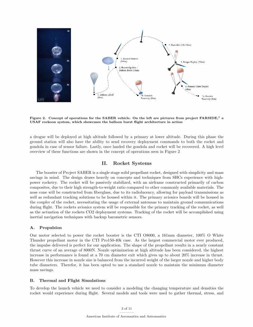
Figure 2. Concept of operations for the SABER vehicle. On the left are pictures from project FARSIDE,1 aUSAF rockoon system, which showcases the balloon burst flight architecture in action
a drogue will be deployed at high altitude followed by a primary at lower altitude. During this phase theground station will also have the ability to send recovery deployment commands to both the rocket andgondola in case of sensor failure. Lastly, once landed the gondola and rocket will be recovered. A high leveloverview of these functions are shown in the concept of operations seen in Figure 2
II. Rocket Systems
The booster of Project SABER is a single stage solid propellant rocket, designed with simplicity and masssavings in mind. The design draws heavily on concepts and techniques from SHCs experience with high-power rocketry. The rocket will be passively stabilized, with an airframe constructed primarily of carboncomposites, due to their high strength-to-weight ratio compared to other commonly available materials. Thenose cone will be constructed from fiberglass, due to its radiolucency, allowing for payload transmissions aswell as redundant tracking solutions to be housed within it. The primary avionics boards will be housed inthe coupler of the rocket, necessitating the usage of external antennas to maintain ground communicationsduring flight. The rockets avionics system will be responsible for the primary tracking of the rocket, as wellas the actuation of the rockets CO2 deployment systems. Tracking of the rocket will be accomplished usinginertial navigation techniques with backup barometric sensors.
A. Propulsion
Our motor selected to power the rocket booster is the CTI O8000, a 161mm diameter, 100% O WhiteThunder propellant motor in the CTI Pro150-40k case. As the largest commercial motor ever produced,the impulse delivered is perfect for our application. The shape of the propellant results in a nearly constantthrust curve of an average of 8000N. Nozzle optimization at high altitude has been considered, the highestincrease in performance is found at a 70 cm diameter exit which gives up to about 20% increase in thrust.However this increase in nozzle size is balanced from the incurred weight of the larger nozzle and higher bodytube diameters. Therefor, it has been opted to use a standard nozzle to maintain the minimum diametermass savings.
B. Thermal and Flight Simulations
To develop the launch vehicle we need to consider a modeling the changing temperature and densities therocket would experience during flight. Several models and tools were used to gather thermal, stress, and
3 of 11
American Institute of Aeronautics and Astronautics

Figure 3. The SABER booster is shown with major sections labeled and key dimensions listed.
range performance of the vehicle. A 6-DOF simulation was built using MATLAB Simulink to model thehigh altitude environment and the reduced drag forces present. The 6-DOF simulation considers a standardatmosphere table for density, the USAF DATCOM models for finding coefficient of drag, and Barrowmanapproximation for the coefficient of lift. The drag and lift coefficients utilize a small angle approximationand extensions for supersonic flow. Using this simulation we input a nominal flight geometry, mass, andlaunch altitude of the rocket (as seen in Figure 3) to get force curves, velocity, and acceleration the rocketwill generally experience during flight. In addition we also consider the impact of launch angles to altitudegained. Results are shown in Figure 4.
Figure 4. Flight profile for a 43kg rocket with nominal flight architecture powered by an O8000 launched atan altitude of 28km. The graphs on the left and center are for the translation motion and forces respectively.On the right is shown two graphs of the upper (30km) and lower (25km) cases of launch height with varyingdegrees of initial launch angles. Max velocity is peaked at around 1200 m/s and the max/min altitude between105-100km
Thermal analysis of the system must consider two environments. The first is the slow ascent of the launchgondola through the upper atmosphere. The second is a high velocity burn and reentry phase. Two mainmethodologies are used to tackle these conditions. First we consider the ascent profile of the rocket whichwill be modeled assuming a quasi-static condition and solving a steady state temperature model for severalaltitudes. The ascent phase of flight will take several hours so the assumption is a reasonable starting point.These results are plotted into a temperature graph in Figure 5.
Depending on the time of launch the unpainted airframe will absorb the thermal energy of the sun andprovide a fair amount of heating during ascent. Our objective is to not utilize active heating surfaces fordesign simplicity, so thermal absorptive paints will be used on the airframe surface. Conversely, the avionics
4 of 11
American Institute of Aeronautics and Astronautics

Figure 5. On the left is a graph of the steady state model assuming an unpainted black carbon fiber bodytube, ground temperature of 315K, and a forced plate convection case with h = 10. The sun angle is measuredrelative to the zenith. On the right is the same model assuming a white painted box which approximates theavionics of the launch gondola.
of the gondola we desire to keep cool, as heating methods are simplistic to implement, a case was run ofwhite paint which provides the least radiative absorption.
The second thermal case is ascent and reentry heating. To determine the actually air temperaturesexperienced we used a Computational Fluid Dynamics (CFD) tool called SimFlow to model a 3-D setup ofthe rocket. In this case the ascent of the rocket during motor burn will be the severest heat stress on therocket with re-entry heating being much less due to drag reduction in the total return velocity. The velocity,local air temperature, and local air pressure curves from the trajectory simulations are setup in the boundaryconditions. The CFD simulation run for an extended time until the air temperature reaches steady values.Results are shown in Figure 6.
Figure 6. The inlet is modeled using a velocity table matching the nominal flight profile at the highest rangeanticipated at 1300 m/s. This also considers the chaining external pressure and temperature using the standardatmosphere. On the left is the rocket temperature contour and velocity streams at motor burnout. A graph ofthe temperature profile at different points of the rocket is shown oo the right for 6 seconds of flight. Followingburnout the temperatures quickly return to the a steady value. Maximum values are for the leading edge ofthe fin at 520K (476 oF)
The maximum temperatures achieved reach generally the same values across the airframe. Our choice ofcarbon fiber airframe presents a challenge in terms of heating which reaches the assumed melting point ofthe epoxy within the carbon fiber tubes. This heating will be assessed by thermal baking coupled to stresstesting alongside selection and modeling of thermal paints. Ultimately these results will feed into specificselection of the carbon fiber type.
5 of 11
American Institute of Aeronautics and Astronautics

C. Airframe and Structures
1. Nose Cone
Due to the large diameter of the O8000, there are no commercially available options for nose cones. Insteadof contracting out the development of the nose cone to a third party, SABER instead elected to leverage thecapabilities of the UAH Engineering Design and Prototyping Facility to manufacture our own nose cones.The plug for the profile of the nose cone will be printed using a Stratasys 3D printer. A negative mold willthen be created from the 3D printed plug. Using custom molds allows for unique geometries to be used thatare not normally available in traditional commercial products allowing for the nose cone to be optimized forout high altitude application. We are planning to use a Haack series nose cone optimized for length andvolume, allowing for the greatest available payload space for least amount of mass. The Haack series of nosecones is a set of mathematically derived profiles designed to offer the lowest coefficient of drag at supersonicspeeds.
2. Body Tubes
In order to maximize the performance of the rocket system, considerations are taken to optimize attributesof the body tubes such as weight, availability, and survivability. The main driving factor of this is the sizeand characteristics of the motor in use. Due to the amount of thrust delivered during flight, three materialsthat could withstand the load incurred were considered for use: 6061-T6 aluminum, pre-impregnated carbonfiber, and G10 fiberglass. Based on approximate densities of each material considered and availability ofeach material, pre-impregnated carbon fiber round tubes at 165 mm inner diameter were selected. Thedensity, strength, and size all met or complied with mission requirements and objectives while the othertwo options would not allow the team to meet mission objectives. As mentioned before, thermal analysiswill play into the final flight selection of materials along side the thermal mitigation techniques used foraerothermal heating.
3. Motor Retention
The motor retainer will be made from 6061 Aluminum due to its strength and high-heat properties. It willbe fastened to the body tube above the motor using set screws to hold it in place. There will be a boltrunning from the top of the motor tube to the center of the motor retainer allowing the motor to be securedin place.
D. Stability and Passive Control Systems
At high altitude the stability of the rocket becomes a unique challenge to the booster. Aerodynamic forcesare around 98% less then those present at ground launch, which is the key efficiency of the SABER vehicle.This also means that cross wind conditions and phenomena such as weather cocking are a non-factor in thepassive stability design. We have opted to use passive fin systems to add net positive stability to the rocket.While air density is low the speed rapidly approaches several mach which creates enough of a torque force atliftoff to provide positive stability. Our main source of torques at launch will be from thrust misalignmentof the motor, both in the airframe mounting and non-uniformity in the exiting propellant velocities. The6-DOF simulation is run considering a thrust misalignment and theoretical wind perturbation torques toquantify the effects of these two sources of initial disturbance. These results are shown below in Figure 7.
Overall the design of the motor mount will prevent angle angles greater then 0.01o, as such the effectsof those torques are fairly small and do not cause a reduction of altitude that would jeopardize missionobjectives.
E. Avionics
The rocket system avionics will be responsible for the real time position, attitude determination, and trackingof the rocket vehicle. Its primarily responsible for deploying recovery systems at the appropriate time.Throughout the duration of the flight radio contact will be maintained so that data may be sent back tothe ground station for recording and real time visualization. However, in the event of radio contact loss, therocket will not need any human intervention in order to safely land.
6 of 11
American Institute of Aeronautics and Astronautics

Figure 7. On the left is a graph of the angular displacements vs altitude from a motor thrust misalignment.As the thrust misalignment decreases we see the flight direction converge. On the upper right is a graph of10 m/s wind tests case (nominal values at 25-30km) of assumed wind toques applied. The bottom right graphrepresents an effective restoring torque force that would exist assuming perturbations of different degreesoccurring during a burn using the rocket velocity profile.
The overall system avionics shall be broken down into two major subsystems: the primary avionics andthe recovery system. The primary avionics shall perform all functions of the avionics under normal flightconditions. It will determine its current position and attitude and make a decision on when to deploy theparachutes. The recovery system will be comprised of circuitry required to drive the deployment system, anindependent APRSa beacon, and an array of separate microcontrollers (MCU), barometers, and deploymentcircuitry. Each separate instance of an MCU, barometer, and deployment circuitry is capable of indepen-dently firing the recovery system in the event of a total primary avionics failure. Each of the backup MCUswill check a PWM signal from the MCU in the primary avionics to ensure its proper operation. In the eventof a primary avionics failure, altitude can be estimated from the attached barometer and the parachutedeployed at an appropriate time. The separate clusters of MCUs, barometers, and deployment circuitry willreach a consensus before firing the deployment system.
1. Sensor Selections
The primary avionics will contain the sensors on the rocket. This includes an IMU, thermometers, barom-eters, magnetometer, cameras, and a GPS. All information, with the exception of images/video will betransmitted to the ground in real time. All information will be recorded onto storage media on-board therocket that may be accessed after recovery. The recovery system will contain many parallel clusters of MCUs,barometers, and parachute deployment circuitry. It will also include an APRS beacon as an extra methodof locating the rocket after flight. The power system of the recovery system will be completely independentof the primary avionics for added safety.
aThe Automatic Packet Reporting System (APRS) is a standardized information packet step that is broadcast on a certainfrequency. Radio receivers tuned to that frequency will publish the packet data to a public database. This is commonly usedfor balloon tracking without the need for a custom ground station, instead using the radio network for its location.
7 of 11
American Institute of Aeronautics and Astronautics

Figure 8. Block diagram of the avionics system.
2. Position and Attitude Determination
Traditional methods within the SHC employ some combination of GPS and barometers to determine position.This is not a viable option for the rocket due to GPS speed and altitude locksb as well as extremely lowambient pressures at the flight altitudes of the mission. While it is possible to have a commercial navigationsystem unlocked, it poses legal complications. As a result, an inertial navigation scheme will be used todetermine the position and attitude of the rocket system in flight. Inertial navigation is a system in whichthe accelerations and angular rates of an object are combined, placed into chosen reference system, andintegrated to yield position and attitude. A three axis strapdown accelerometer package and three axisstrapdown gyroscope package will gather the body accelerations and rotations. These will be converted intoearth frame coordinates and will be adjusted for gravity. Afterwards, it will be numerically integrated toyield the position and altitude of the rocket vehicle. The chosen numerical integration technique is Simpsons1/3 due to its accuracy and computational requirements.
3. Communications
An onboard RF radio will transmit telemetry throughout the flight. This will include altitude, position, andthe status of the systems. Any communication needed for the payload will also be sent via the radio on-boardthe rocket. This is to mitigate any interference between systems. The only communications received for therocket will be manual overrides. If the launch needs to be aborted, the signal will be sent both to the gondolaand to the rocket and the necessary steps will be taken to ensure the safety of the entire system. Along withaborts, there is an override for parachute deployment on descent. If the parachute has not deployed at theappropriate altitude, a command can be sent to immediately deploy the parachute. This will be the case ifthere is a failure in the drogue and the main needs to be opened quickly.
F. Recovery
The recovery system for this design will be composed of a two-stage drogue and main descent system. Thedrogue will be deployed at approximately 70 km and will allow the rocket to maintain stability at a descentrate of approximately 44 m/s. The drogue chute will be 0.6 meter in diameter. Main deployment will occurat approximately 4 km and will slow the rocket for impact. The main will be 3 meters in diameter, allowinga descent rate below 6 m/s. The graphs below in Figure 9 show the descent rate and trajectory of our rocket.
bStandard commercial GPS are limited by either altitude, speed or both. These ranges are useally >60km or beyond severalhundred m/s. These limits are to prevent the use of cheap GPS systems as guidance for missiles. A GPS can be unlockedby the manufacturer, but would require the project to adhere to export controls due to the avionics possessing a sensitivitytechnology.
8 of 11
American Institute of Aeronautics and Astronautics

Figure 9. Recovery graphs of parachute sizes vs velocity and typical landing profile. On the left is a typicalflight profile of the rocket during burn and reentry. The graph on the right is terminal velocity graph withparachute size for the primary. The solid green line is our design parameter to be under.
III. Balloon Overview
The balloon system will consist of a single zero pressure balloon, with an attached launch gondola thatsecures the rocket payload. This balloon will be assembled using a sealing system developed for this project.The balloon will be approximately 20 meters tall at apogee, and will float at around 28 km above sea level.All communication with the balloon system will be transmitted by radio, and all on board telemetry will becarried out in an avionics package on-board the launch gondola. Ignition operations will occur on the launchgondola and requires a ground command to be performed.
A. Launch Gondola
The launch gondola will be consist of two launch rails made of 1515 aluminum railing. The top of the gondolawill be a ring shape that will be integrated into the balloon envelope by securing the upper part of the ringto the gore seals. The parachutes for recovery will be located on the sides of the launch rails and will beattached by angled brackets, so that the parachutes will deploy without colliding with the upper part of thegondola. The avionics box will be secured on these brackets, and will contain all of the necessary avionicssensors for the balloon system. The rocket will be resting on the rear securement plate.
Figure 10. Launch gondola overview
9 of 11
American Institute of Aeronautics and Astronautics

B. Motor Ignition
The motor ignition system used is a dual redundant igniter system. Two igniters will be attached to awooden dowel for support as they are inserted all the way up the core of the motor. The igniters used forthis motor are low-voltage electric matches. Safety is a critical aspect of ignition as electric matches requiremuch lower voltage and amperage, which puts them at risk for accidental ignition. The ignition system willuse static wicks like those found on airplanes to dissipate excess charge on the airframe, preventing earlyignition.
C. Avionics
The gondola avionics will be responsible for the real time position, attitude determination and tracking ofthe gondola and ignition of the rocket motor. It shall also be responsible for the firing of the gondolasdeployment system at the appropriate time. Throughout the duration of the flight, radio contact must bemaintained so that data may be sent back to the ground station for recording and real time visualization.However, in the event of radio contact loss, the gondola will not need any human intervention in order tobegin recovery or abort procedures.
The gondola avionics will be broken down in the same manner as the rocket with the addition of a rocketigniter. The largest difference between the two, besides the additional components, is that the gondola willrely on its GPS for position since it will be under the GPS locking altitude. The IMU and GPS data will becombined in a kalman filter in order to produce more accurate results.
1. Sensor Selection
The primary avionics will contain the sensors on the gondola. This includes an IMU, thermometers, barom-eters, magnetometer, cameras, and a GPS. All information, with the exception of images/video will betransmitted to the ground in real time. All information will be recorded onto storage, media on-board therocket will be accessed after recovery. In addition to this, the gondola will house the rocket ignition circuitry.The recovery system will contain many parallel clusters of MCUs, barometers, and recovery deployment cir-cuitry. It will also include an APRS beacon as an extra method of locating the gondola after flight. Thepower system of the recovery system will be completely independent of the primary avionics for added safety.
2. Communication
The gondola will also have its own dedicated RF radio connected to the ground station. Like the rocket, itwill transmit telemetry throughout the flight including: altitude, rotation, power, and tilt angles. This datais used to ensure a safe condition for launch of the rocket. The final launch and ignition command will besent to the gondola, not the rocket, only when the specified conditions for launch are met.
D. Recovery
The recovery of the gondola platform will be similar to that of the rocket drogue parachute system. De-ployment will be actuated by a CO2 system. Recovery deployment will occur right after balloon separationor during abort procedures at an altitude of approximately 28-20km. The main parachute for the gondolaplatform will be 3.7 meters in diameter, which will allow for a descent rate of less than 6 m/s.
IV. Launch Site Analysis and Operations
Our launch site for this vehicle will require a fairly large area to accommodate the balloon ascent drift.Research has identified the Black Rocket desert as a strong candidate. For a detailed analysis of the launchrange requirements the 6-DOF simulation is integrated into a total simulation that assumes a linear ascentof the balloon with expanding envelope as well as the drogue and primary rocket parachute recovery.
A. Vehicle Drift Analysis
Wind data and direction are gathered from local airports in the region. Three case studies are run to to givean idea of the drift possible for this launch vehicle. In figure 11 we have shown three cases of possible drift
10 of 11
American Institute of Aeronautics and Astronautics

at Black Rock desert
Figure 11. Total flight trajectory using wind data gathered from Reno NV for the year 2017. This projectionassumes 28km launch altitude and no time drifting at float. Wind data are averaged values for the monthsselected. AM and PM are the two NOAA sounding balloon flights.
A strong factor of launch date selection is the condition of stratospheric turnaround winds, which is whenthe upper atmospheric wind direction changes almost 180o and would allow the vehicle to sit at float andhead back towards the launch point thereby reduce the required landing space. This would not limit theairspace requirements persay, but it would allow for a smaller zone of impact and reduce the public risk andscale of recovery operations.
B. Ground Support Operations
On site, there will be two separate ground stations for the flight, each dealing with either the rocket orballoon. The ground stations will facilitate all communications to the systems and display any data to alaptop on the ground. Most data will be plotted in real-time using MATLAB and any commands needed tobe sent will be through a graphic user interface (GUI).
Each station will track its respective system independently. The major concern is possible loss of com-munication; if that were to occur there would be no ability to accurately track or provide launch commandsto the systems. As a safety mitigation, separate trackers transmitting to APRS network will be placed onthe rocket and gondola, this data can be accessed from the internet as a backup for location data.
V. Conclusion
The SABER team has outlined a launch vehicle design that can send a 1-2kg payload to altitudesexceeding 100km. Our design has utilized standard commercial systems when possible to reduce developmenttime and costs. Simulations have been developed to identify the thermal and stress loads the vehicle willundergo. The project is currently in Phase B development with an anticipated launch in 2019-20.
Acknowledgments
We would like to thank Dr. Francis Wessling for mentoring the project and the entire SABER team.
References
1http://www.whiteeagleaerospace.com/operation-farside/.
11 of 11
American Institute of Aeronautics and Astronautics