overview of the emerging hevc screen content coding extension · 1 overview of the emerging hevc...
TRANSCRIPT

MITSUBISHI ELECTRIC RESEARCH LABORATORIEShttp://www.merl.com
Overview of the Emerging HEVC Screen Content CodingExtension
Xu, J.; Joshi, R.; Cohen, R.A.
TR2015-126 September 2015
AbstractA Screen Content coding (SCC) extension to High Efficiency Video Coding (HEVC) is cur-rently under development by the Joint Collaborative Team on Video Coding (JCT-VC), whichis a joint effort from the ITU-T Video Coding Experts Group and the ISO/IEC Moving Pic-ture Experts Group. The main goal of the HEVC screen content coding standardizationeffort is to enable significantly improved compression performance for videos containing asubstantial amount of still or moving rendered graphics, text, and animation rather than, orin addition to, camera-captured content. This paper provides an overview of the technicalfeatures and characteristics of the current HEVCSCC test model and related coding tools,including intra block copy, palette mode, adaptive colour transform, and adaptive motion vec-tor resolution. The performance of the screen content coding extension is compared againstexisting standards in terms of bit-rate savings at equal distortion.
2015 IEEE Transactions on Circuits and Systems for Video Technology
This work may not be copied or reproduced in whole or in part for any commercial purpose. Permission to copy inwhole or in part without payment of fee is granted for nonprofit educational and research purposes provided that allsuch whole or partial copies include the following: a notice that such copying is by permission of Mitsubishi ElectricResearch Laboratories, Inc.; an acknowledgment of the authors and individual contributions to the work; and allapplicable portions of the copyright notice. Copying, reproduction, or republishing for any other purpose shall requirea license with payment of fee to Mitsubishi Electric Research Laboratories, Inc. All rights reserved.
Copyright c© Mitsubishi Electric Research Laboratories, Inc., 2015201 Broadway, Cambridge, Massachusetts 02139


1
Overview of the Emerging HEVC Screen ContentCoding Extension
Jizheng Xu, Senior Member, IEEE, Rajan Joshi, Member, IEEE, and Robert A. Cohen, Senior Member, IEEE
Abstract—A Screen Content coding (SCC) extension to HighEfficiency Video Coding (HEVC) is currently under developmentby the Joint Collaborative Team on Video Coding (JCT-VC),which is a joint effort from the ITU-T Video Coding ExpertsGroup and the ISO/IEC Moving Picture Experts Group. Themain goal of the HEVC screen content coding standardization ef-fort is to enable significantly improved compression performancefor videos containing a substantial amount of still or movingrendered graphics, text, and animation rather than, or in additionto, camera-captured content. This paper provides an overview ofthe technical features and characteristics of the current HEVC-SCC test model and related coding tools, including intra blockcopy, palette mode, adaptive colour transform, and adaptivemotion vector resolution. The performance of the screen contentcoding extension is compared against existing standards in termsof bit-rate savings at equal distortion.
Index Terms—HEVC, video coding, screen content coding.
I. INTRODUCTION
IN January 2013, the first edition of the High EfficiencyVideo Coding standard, also known as HEVC version 1 [1],
was finalized. This work was done by the Joint CollaborativeTeam on Video Coding (JCT-VC), which was establishedjointly in 2010 by ITU-T Study Group 16 (VCEG) andISO/IEC JTC1/SC 29/WG 11 (MPEG). One of the primaryrequirements of that standard was that it demonstrates asubstantial bit-rate reduction over the existing H.264/AVC [2]standard. Both the initial development of HEVC and theearlier development of H.264/AVC focused on compressingcamera-captured video sequences. Although several differenttest sequences were used during the development of thesestandards, the camera-captured sequences exhibited commoncharacteristics such as the presence of sensor noise and anabundance of translational motion. Recently, however, therehas been a proliferation of applications that use video devicesto display more than just camera-captured content. Theseapplications include displays that combine camera-capturedand computer graphics, wireless displays, tablets, automotivedisplays, screen-sharing, etc. [3]. The type of video contentused in these applications can contain a significant amount ofstationary or moving computer graphics and text, along withcamera-captured content. However, unlike camera-capturedcontent, screen content frequently contains no sensor noise,and such content may have large uniformly flat areas, repeated
Copyright (c) 2015 IEEE. Personal use of this material is permitted.However, permission to use this material for any other purposes must beobtained from the IEEE by sending an email to [email protected]
J. Xu is with Microsoft Research, Beijing 100080, China.R. Joshi is with Qualcomm Technologies, Inc.R. A. Cohen is with Mitsubishi Electric Research Laboratories.
patterns, highly saturated or a limited number of differentcolours, and numerically identical blocks or regions amonga sequence of pictures. These characteristics, if properlyleveraged, can offer opportunities for significant improvementsin compression efficiency over a coding system designedprimarily for camera-captured content.
During the development of HEVC, decisions as to whichtools to incorporate into the version 1 standard were madeprimarily based on their coding performance on camera-captured content. Several tool proposals showed that thecharacteristics of screen-content video can be leveraged toobtain additional improvements in compression efficiency overthe HEVC version 1 standard under development.
Residual Scalar Quantization (RSQ) and Base Colors andIndex Map (BCIM) [4] were proposed early during the HEVCdevelopment process. Because screen content often has highcontrast and sharp edges, RSQ directly quantized the intraprediction residual, without applying a transform. BCIM tookadvantage of the observation that the number of unique coloursin screen content pictures is usually limited as compared tocamera-captured content. RSQ and BCIM could respectivelybe considered early forms of transform skip, which is partof HEVC version 1, and palette mode, which is describedin Section III-B. Additional modes such as transform bypasswhere both the transform and quantization steps are bypassedfor lossless coding, and the use of differential pulse codemodulation (DPCM) for sample-based intra prediction wereproposed in [5].
Because screen content often contains repeated patterns,dictionary and Lempel-Ziv coding tools were shown to beeffective at improving coding efficiency, especially on picturescontaining text and line graphics [6], [7], [8]. These tools storea dictionary of previously-coded samples. If a block or codingunit contains strings of samples that are already contained inthe dictionary, then a pointer to the dictionary can be signalled,thus avoiding the need to transform and quantize a predictionresidual.
In January 2014, the MPEG Requirements subgroup pub-lished a set of requirements for an extension of HEVC forcoding of screen content [3]. This document identified threetypes of screen content: mixed content, text and graphics withmotion, and animation. Up to visually lossless coding perfor-mance was specified, for RGB and YUV 4:4:4 video having 8or 10 bits per colour component. Given the earlier publisheddrafts of these requirements, along with the existing evidencethat additional tools could improve the coding performance ofHEVC on screen content material, VCEG and MPEG issued ajoint Call for Proposals (CfP) for coding of screen content [9].

2
At the next JCT-VC meeting in March 2014, seven re-sponses to the CfP were evaluated. After identifying the toolsthat produced significant improvements in performance forscreen content, several core experiments (CEs) were defined.The tools included in these CEs were: intra block copyingextensions, line-based intra copy, palette mode, string match-ing for sample coding, and cross-component prediction andadaptive colour transforms. After evaluating the outcome ofthe CEs and related proposals, the HEVC Screen ContentCoding Draft Text 1 [10] was published in July 2014.
This paper gives an overview of the tools and coding perfor-mance associated with this new HEVC screen content codingextension. At the time of this writing, the current version of thetext is Draft 2 [11]. Section II describes screen content codingsupport in HEVC version 1 and HEVC range extensions. Newcoding tools in the HEVC screen content coding extension(HEVC-SCC) are described Section III. Section IV presentsnew encoding algorithms introduced during the developmentof HEVC-SCC. Coding performance comparisons are dis-cussed in Section V, and Section VI concludes the paper.
II. SCREEN CONTENT CODING SUPPORT IN HEVC
The HEVC screen content coding extension (HEVC-SCC)is developed based on HEVC version 1 [1] and HEVC rangeextensions (HEVC-RExt) [12]. Thus, it inherits the codingstructure and coding tools of HEVC version 1 and HEVC-RExt. HEVC-SCC also maintains backward compatibility toHEVC version 1 and HEVC-RExt. As an example, an HEVC-SCC decoder can decode HEVC version 1 bit-streams and thedecoded videos are identical to those produced by an HEVCversion 1 decoder. Screen content, as one class of video, wasalso considered during the development of HEVC version 1and HEVC-RExt, although it was not the main focus of thosestandards. In the following subsections, the structure of HEVCand HEVC-RExt, along with the coding tools that primarilytargeted screen content, are briefly introduced.
A. HEVC version 1
HEVC version 1 follows the conventional hybrid codingstructure as in previous video coding standards. An inputimage is first divided into image blocks, referred to as codingtree units (CTU), of pre-defined size. The size of a CTUcan be of 16×16, 32×32, or 64×64 luma samples. A CTUcontains corresponding chroma samples according to the inputcolour format. A quad-tree split, with a CTU as the root,divides the CTU into one or more coding units (CU). A CU issquare-shaped and can have 8×8, 16×16, 32×32, or 64×64luma samples and corresponding luma samples. A CU canbe classified as an intra CU or an inter CU, and it is furtherdivided into one, two or four prediction units (PU). For an intraCU, spatially neighboring reconstructed samples are used topredict its PUs. For an inter CU, a motion vector is sent foreach PU, which is used by a motion compensation process togenerate the prediction from other pictures.
A transform quad-tree is also defined for a CU to indi-cate how the predicted residual are decorrelated with spatialtransforms after the prediction process. A leaf of a transform
quad-tree is referred to as a transform unit (TU). An integertransform is applied to each TU. All transforms applied toan inter CU and most transforms applied to an intra CU arederived to approximate the discrete cosine transform (DCT)of appropriate size. The only exception is the 4×4 transformapplied to an intra CU, which is designed to approximate thediscrete sine transform (DST).
During the development of HEVC version 1, it was observedthat for screen content, spatially transforms mentioned abovedo not always help in improving coding efficiency. For mostscreen content, the images are sharp, containing irregularedges and shapes. After the prediction process, the residualsignal may already be sparse because the background canbe precisely predicted while irregular foreground may not. Insuch a case, the existing transform will spread the energy tomost frequencies instead of compacting the energy, therebydestroying the sparsity of the residual, leading to low codingefficiency during entropy coding. Thus, for those blocks, skip-ping the transform and quantizing data in the spatial domaincan be a better choice, as was demonstrated for H.264/AVCin [13]. HEVC version 1 can skip the transform for a 4×4 TU,whether it is intra [14] or inter [15]. This transform skip isequivalent to applying an identity transform to the TU. Thus,the quantization process after applying transform skip is thesame as that applied after the spatial transform. It turns out thatsuch a simple design can lead to significant coding efficiencyimprovement for screen content, e.g. the bit-saving broughtby the transform skip mode is about 7.5% for typical 4:2:0screen content [15]. When applied to 4:4:4 screen content, thecoding gain for transform skip is much larger [16], rangingfrom 5.5% to 34.8%.
B. HEVC-RExt
After HEVC version 1, HEVC-RExt was developed tosupport non-4:2:0 colour formats, e.g. 4:4:4 and 4:2:2v, andhigh bit-depth video, e.g. up to 16-bit. Because most screencontent is captured in the 4:4:4 colour format, which is notsupported by HEVC version 1, more attention was given tocoding of screen content in HEVC-RExt. The coding tools thatimproved the coding efficiency for screen content in HEVC-RExt compared with HEVC version 1 include:
1) Improvements to transform skip mode: As mentionedabove, HEVC version 1 only supports transform skip for 4×4TUs. HEVC-RExt extends transform skip to all TUs, regard-less of their size [17]. Enabling transform skip for all TUshas two benefits. One is that the coding efficiency for screencontent can be further improved. The other is that encodershave the flexibility to exploit the transform skip mode. Forexample, a specific encoder may support only large transformunits so that the encoding complexity can be reduced. Iftransform skip is allowed only for 4×4 TUs, the performanceof such an encoder would be affected adversely since it cannotexploit the benefit brought by transform skip, which can bemuch more noticeable for screen content. Other improvementsinclude coefficient coding for transform skip blocks. For an in-tra transform block, when a spatial transform is applied to theresidual, the energy is compacted at the upper-left corner of the

3
block. However, when transform skip is used on a transformblock, because its prediction is from the adjacent upper rowand/or left column of samples, the prediction error is higherat the bottom-right corner compared to the upper-left corner.The different characteristics of the residual of transform skipblocks relative to transformed blocks make entropy codingdesigned for transformed blocks inefficient when applied totransform skip blocks. A simple yet effective solution adoptedin HEVC-RExt is to rotate the residual of transform skipblocks by 180 degrees [18], [19]. This rotation process isonly applied to 4×4 intra transform skip blocks [20]. Anotherimprovement for the entropy coding of the transform skipblocks is that a single context is used to code the significantcoefficient map. For transformed blocks, the context used forsignificance coding depends on the position (frequency) of thecoefficient. However, since all the coefficients of a transformskip block are from the residual in the spatial domain, using asingle context is more reasonable that using different contextsdepending on position.
2) Residual differential pulse code modulation (RDPCM):Even after intra prediction, there is still correlation in theresidual signal which can be exploited. Residual differentialpulse code modulation (RDPCM) predicts the current residualusing its immediately neighboring residual. In HEVC-RExt,RDPCM was proposed for intra lossless coding [21]. Then itwas extended to lossy coding [22] and inter coding [23]. InRDPCM, the left reconstructed residual or the above one isused to predict the current residual, depending on whether theblock uses horizontal or vertical RDPCM. RDPCM is usedonly for transform skip blocks. In inter mode, flags are sentto indicate whether RDPCM is used and if so, its direction.In contrast, RDPCM in intra mode is applied in the samedirection as the intra prediction direction. Because of this,using the reconstructed residual to predict the current residualis identical to using reconstructed samples to predict thecurrent sample in intra mode (if clipping of the reconstructedsample is ignored). From this perspective, RDPCM shortensthe prediction distance, leading to better prediction. For screencontent, a short distance prediction is quite useful becauseusually the content is sharp and changes rapidly.
3) Cross-component prediction (CCP): CCP [24] and itspredecessor LM Chroma mode [25] were proposed to ex-ploit correlation among colour components [24]. In CCP, theresidual of the second or third colour component can bepredicted from the residual of the first colour componentmultiplied by a scaling factor. The factor is selected from{0,± 1
8 ,±14 ,±
12 ,±1} and is signalled to the decoder. One
advantage of performing prediction on residuals in the spatialdomain is that the reconstruction process for the second andthird colour components does not depend on reconstructedsamples of the first colour component. Hence the reconstruc-tion process for different colour components can be performedin parallel once the residuals for the three colour componentsare available. Although such a design can still leave a cer-tain degree of correlation among colour components, it wasdemonstrated that CCP can significantly improve the codingefficiency when coding videos having the RGB colour format.Because much screen content is captured in the RGB domain,
CCP is very effective in coding of screen content.4) Other improvements: Some other aspects of HEVC-
RExt, although not specifically designed for screen contentcoding, also improve the coding efficiency for screen content.For example, the initialization of Rice parameters based onprevious similar blocks was primarily designed for high bit-depth coding; but it also showed improvement for codingscreen content [26].
C. HEVC-SCCUnlike HEVC version 1 and HEVC-RExt, the tools added
for the HEVC-SCC extension focus primarily on coding screencontent. To illustrate the framework of SCC, an SCC encoderis shown Fig. 1. As shown in the figure, HEVC-SCC is basedon the HEVC framework while several new modules/tools areadded. The new coding tools are:
• Intra block copy (IBC): HEVC-SCC introduces a newCU mode in addition to the conventional intra and intermodes, referred to as intra block copy (IBC). When a CUis coded in IBC mode, the PUs of this CU find similarreconstructed blocks within the same picture. IBC can beconsidered as ”motion compensation” within the currentpicture.
• Palette mode: For screen content, it is observed thatfor many blocks, a limited number of different colourvalues may exist. Thus, palette mode enumerates thosecolour values and then for each sample, sends an indexto indicate to which colour it belongs. Palette modecan be more efficient than the prediction-then-transformrepresentation.
• Adaptive colour transform (ACT): Because much screencontent uses the RGB colour space, removing inter-colourcomponent redundancy is important for efficient coding.Earlier work with adaptive colour space transforms wasshown to yield improvements in coding efficiency [27].In HEVC-SCC, a CU-level adaptation is used to convertresidual to different colour spaces. More precisely, animage block in the RGB colour space can be codeddirectly. Or it can be converted adaptively to the YCoCgcolour space during coding.
• Adaptive motion vector resolution: Unlike camera-captured content, where motion is continuous, screencontent often has discrete motion, which has a granularityof one or more samples. Thus, for much screen content,it is not necessary to use fractional motion compensa-tion. In HEVC-SCC, a slice-level control is enabled toswitch the motion vectors between full-pel and fractionalresolutions.
The details of these new tools are described in the followingsections.
III. NEW CODING TOOLS IN HEVC-SCCThis section describes the new coding tools that were
adopted into the HEVC-SCC text specifications, i.e. normativespecifications. When relevant, some non-normative aspects areincluded in this section, and a more complete description ofnon-normative aspects of the tools is included in the sectionon encoding algorithms.

4
+
Coder Control
Transform & Quant.
De-quant. & Inv. transform
+
Deblocking & SAO filters
Intra block copy
Intra prediction
Motion compensation
Palette coding
Adaptive color transform
Inv. color transform
Block vector estimation
Hash-based block matching & motion estimation
CABAC
Partitioning & mode information
Palette & index map
Transf. Coef.
Block vectors
Motion vectors
SAO parameters
Bitstreams
Split into CTUs
Fig. 1. Encoder for screen content coding extension.
A. Intra Block Copy
Intra Block Copy (IBC) is a coding tool similar to inter-picture prediction. The main difference is that in IBC, a pre-dictor block is formed from the reconstructed samples (beforeapplication of in-loop filtering) of the current picture. Previ-ously, IBC was proposed in the context of AVC/H.264 [28] butthe coding gain was not consistently high across different testsequences, which at the time were primarily camera-capturedsequences and not screen content material. A CU based IBCmode was proposed during the HEVC-RExt development [29].A modified version [30] was adopted into the HEVC-RExt textspecification but was later removed. IBC has been a part ofHEVC-SCC test model since the beginning of the HEVC-SCCdevelopment.
At the early stage of HEVC-SCC development, IBC wasperformed at the coding unit (CU) level. A block vector wascoded to specify the location of the predictor block. However,since both IBC and inter mode share the concept of vectorsrepresenting displaced blocks, it is natural to unify the designof IBC and inter mode. Methods to unify these modes [31],[32] have shown that also using the inter mode syntax designfor IBC is an adequate choice.
In the current HEVC-SCC design, IBC is performed atthe prediction unit (PU) level and is treated as an inter PU.Specifically, using the inter mode design, the current picturecan also be used as a reference picture for IBC. When aPU’s reference picture is the current picture, it means thatits prediction is performed from the reconstructed samples,before in-loop filtering in the encoder, of the current picture,
which corresponds to the original IBC design. When thecurrent picture is used as a reference, it is marked as a long-term reference. After the current picture is fully decoded, thereconstructed picture after in-loop filtering is added to thedecoded picture buffer (DPB) as a short-term reference, whichis identical to what HEVC version 1 does after decoding apicture. Using the inter mode design to enable IBC at the PUlevel enables greater flexibility in combining IBC and intermode. For example, an inter CU can have two PUs, one usingconventional inter mode and the other using IBC; a PU canbe bidirectionally predicted from an average between a blockfrom the current picture and a block from a previous picture.
However, unification between IBC and inter mode does notmean that IBC can be directly implemented as an inter modein practice. The implementation of IBC can be much differentfrom that of inter mode in many platforms. Such differencesexist because when the current picture is used as a reference,it has not been fully reconstructed, whereas the other referencepictures have been decoded and stored in the DPB.
For IBC mode, because the block to be processed and itsprediction are from the same picture, several constraints havebeen placed to avoid affecting other modules adversely. Theconstraints for IBC mode are:
• The predictor block may not overlap the current CU, toavoid generating predictions from unreconstructed sam-ples.
• The predictor block and the current CU should be withinthe same slice and the same tile. Otherwise, there will bedependency among different slices or tiles, which affect

5
CTU
BV
block predictor
current CU
Fig. 2. Search area for IBC (shown in gray).
the parallel processing capability provided by the designof slices and tiles.
• The predictor block is normatively required to be entirelycontained in the search region shown in Fig. 2. It isso designed to avoid affecting the parallel processingcapability provided by wavefronts. To simply the design,the constraint still holds even when wavefronts are notbeing used.
• For constrained-intra profiles, the samples of the predictorblock must be from other intra blocks or IBC blocks.
• The block vector precision is full-pel.
B. Palette mode
Palettes are an efficient method for representing blockscontaining a small number of distinct colour values. Ratherthan apply a prediction and transform to a block, palettemode signals indices to indicate the colour values of eachsample. An early use of palettes was in the conversion of 24-bit RGB images to 8-bit index images to save on RAM orvideo memory buffer space. A CU based palette coding modewas proposed during the HEVC-RExt development [33]. Thepalette mode was further refined through core experiments andAd Hoc Group (AHG) discussions and was adopted [34] intothe SCC text specification.
A palette refers to a table consisting of representative colourvalues from the CU coded using the palette mode. For eachsample in the CU, an index into the current table is signalled inthe bit-stream. The decoder uses the palette table and the indexto reconstruct each sample of the CU. Each entry in the palettetable consists of three components (RGB or YCbCr). For 4:2:0and 4:2:2 colour formats, if no chroma components are presentfor the current sample position, only the first component isused for reconstruction. A special index, known as an escapeindex, is reserved to indicate that a sample does not belongto the palette. In such a case, in addition to coding the escapeindex, the quantized values of the component(s) of the escapesample are also coded in the bit-stream.
The size of the palette table is referred to as the palette size.If the palette size is nonzero, then the indices from zero topalette size minus one are reserved for denoting entries fromthe palette, and the escape index is set equal to the palette
4
R/Y G/Cb B/Cr
Index 0
Index 1
Index 2
Index 3
Index 4
CU
palette
escape
0 32240 80 80
100 50 20
200 200 250
250 250 150
Fig. 3. Palette example (palette size = 4).
size. An example for this coding is illustrated in Fig. 3. Onthe encoder side, palette table derivation is performed. This isdiscussed further in Section IV-C. Normative aspects of palettecoding can be divided into two categories: coding of the palettetable and coding of the palette indices of the samples in theCU.
The palette needs to be signalled to the decoder. It is typicalthat a palette shares some entries with neighboring blocksthat are coded using the palette mode. To exploit this sharing,the palette table is coded using a combination of predictionfrom palette entries of previously coded CUs and new paletteentries that are explicitly signalled. For prediction, a predictorpalette consisting of palette entries from the previous CUscoded in palette mode is maintained. For each entry in thepalette predictor, a flag is signalled to specify whether thatentry is reused in the current palette. The collection of flagsis signalled using run-length coding of zeros. The run-lengthsare coded using exponential Golomb code of order 0. Aftersignalling the predicted palette entries, the number of newpalette entries and their values are signalled. This is illustratedin Fig. 4. In this example, the predictor palette contains sixentries. Out of these, three are reused in the current palette(0th, 2nd and 3rd). These are assigned indices 0, 1 and 2,respectively, in the current palette. This is followed by 2 newentries.
For the first CTU of each slice, tile and CTU row (whenwavefronts are used), the palette predictor is initialized usinginitialization entries signalled in the picture parameter set(PPS) or to zero. After a CU has been coded in palette mode,the palette predictor is updated as follows. First all the entriesfrom the current palette are included in the predictor palette.This is followed by all the entries that were not reused fromthe previous predictor palette. This process is continued tillall the entries from the previous predictor palette that werenot reused are included or the maximum palette predictor sizeis reached. The updated predictor palette is illustrated on theright side in Fig. 4.
To code the palette indices, first a flag,palette escape val present flag, is coded to indicate whetherthere are any escape indices present in the current CU. Twodifferent scans may be used to code the palette indices ina CU, namely, horizontal traverse scan and vertical traversescan as shown in Fig. 5. In the following description, a

6
Reuse flag
1
0
1
1
0
0
Index
0
1
2
current palette
3
4Reused palette entries (3)
New palette entries (2), signalled
G/Y B/Cb R/Cr
G0 B0 R0
G2 B2 R2
G3 B3 R3
G3N B3N R3N
G4N B4N R4N
Index
0
1
2
3
4
5
predictor palette
G/Y B/Cb R/Cr
G0 B0 R0
G1 B1 R1
G2 B2 R2
G3 B3 R3
G4 B4 R4
G5 B5 R5
Index
0
1
2
3
4
Updated predictor palette
G/Y B/Cb R/Cr
G0 B0 R0
G2 B2 R2
G3 B3 R3
G3N B3N R3N
G4N B4N R4N
5 G1 B1 R1
6 G4 B4 R4
7 G5 B5 R5
Fig. 4. Construction of palette from predictor palette and new explicitly signalled entries.
horizontal traverse scan is assumed. If the scan is verticaltraverse, the CU index map may be transposed before coding(or after decoding). The direction of the scan is signalledusing palette transpose flag.
Since screen content may typically contain flat areas withuniform or near-uniform sample values, run-length codingof palette indices is an efficient method of compression.Additionally, it is observed that indices in consecutive rowsor columns may be identical. To exploit this, each palettesample may be coded in one of two palette sample modes,COPY INDEX MODE and COPY ABOVE MODE, whichare signalled in the bitstream as palette run type flag. InCOPY INDEX MODE, the palette index is coded followedby a run value which specifies the number of subsequent sam-ples that have the same index. The index values are coded us-ing a truncated binary code [35]. In COPY ABOVE MODE,the palette index is copied from the previous row. This is fol-lowed by a run value which specifies the number of subsequentpositions for which the index is copied from the previous row.Both COPY INDEX MODE and COPY ABOVE MODEruns may span multiple rows. In COPY ABOVE MODE onlythe run value is signalled but not the index. If the indexfor a particular sample corresponds to the escape index, thecomponent value(s) are quantized and coded. Fig. 6 shows anexample of palette sample modes, indices and run values fora 4×4 block1.
The run coding uses a concatenation of unary code andexponential Golomb code of order zero. The code can bedescribed as follows. A run of zero is represented as ”0”. Arun of length L ≥ 1 is represented as a concatenation of ”1”and the exponential Golomb code (order zero) representationfor (L− 1). Both prefix and suffix are truncated based on themaximum possible run value when the run continues to theend of the block. The code is specified in Table I.
Several redundancies are exploited in the coding of paletteindices to reduce the number of syntax elements and makethe coding more efficient. For example, when the palettesize is equal to 0 or when the palette size is equal to1 and there are no escape indices present, then the in-
1The 4×4 block is chosen for convenience. The minimum palette blocksize is 8×8.
TABLE IBINARIZATION FOR THE PALETTE RUN VALUE.
value prefix suffix0 0 -1 10 -2-3 110 X4-7 1110 XX7-15 11110 XXX
. . . . . . . . .
dex values can be inferred, thereby eliminating the needto signal the palette sample modes, indices and runs. Fur-thermore a COPY ABOVE MODE may not occur in thefirst row (or column for vertical traverse scan) and maynot follow COPY ABOVE MODE. This is used in inferringCOPY INDEX MODE under these conditions.
C. Adaptive colour transform
Much screen content is captured in the RGB colour space.For an image block in RGB colour space, usually there canbe strong correlation among different colour components suchthat a colour space conversion is useful for removing inter-colour component redundancy. However, for screen content,there may exist many image blocks containing different fea-tures having very saturated colours, which leads to less cor-relation among colour components. For those blocks, codingdirectly in the RGB colour space may be more effective.To handle different characteristics of image blocks in screencontent, a RGB-to-Y CoCg conversion [36] as shown in thefollowing equation was investigated, and it turned out to beeffective. YCo
Cg
=
1/4 1/2 1/41/2 0 −1/2−1/4 1/2 −1/4
RGB
(1)
When this colour transform is used, both the input imageblock and its corresponding prediction use the same conver-sion. Because the conversion is linear, it is identical to havingthe transform applied to residuals in the spatial domain whenthe prediction processes in different colour components areconsistent. Thus, in HEVC-SCC, the conversion is applied

7
1 1 1 1 1
1 1 1 1 1
1
1
1
1
1
1
0 0 00
0 0 00 0 0 00
0 0 00 0 0 00
0
0 0
00
0 0
0
0 00
0 00
0 00
0 0
0
0
0 0
0 0 00
1
0
1 1 1 1
1 1 1 1 1
1
1
1
1
1
1
0 0 00
0 0 00 0 0 00
0 0 00 0 0 00
0
0 0
00
0 0
0
0 00
0 00
0 00
0 0
0
0
0 0
0 0 00
horizontal traverse scan vertical traverse scan
0
Fig. 5. Horizontal and vertical traverse scans for the coding of palette indices.
Mode Index Run
COPY_INDEX 0 3
COPY_INDEX 4 0
COPY_INDEX 1 1
COPY_INDEX 2 0
COPY_INDEX 3 0
COPY_ABOVE - 5
COPY_INDEX 2 0
0 0 0 0
2 1 1 4
3 1 1 4
2 1 1 4
Fig. 6. Example of palette sample modes, indices, and run values for a 4×4 block.
on the residual [37], which makes the prediction process fordifferent colour components independent. It is also noted forintra-coded blocks, when the intra prediction directions fordifferent colour components are not the same, the colourtransform is not allowed to be used. This limitation is specifiedbecause when the intra prediction directions are different, thecorrelation among colocated samples across colour compo-nents is decreased, making the colour transform less effective.The colour transform also changes the norm of differentcomponents. To normalize the errors in different colour spaces,when the above transform is used for an image block, a setof QP offsets (−5,−5,−3) is applied to those three colourcomponents [38] during quantization. After the quantizationand reconstruction, an inverse transform is applied to thequantized residual so that the reconstruction is still kept inthe input colour space.
To limit the dynamic range expansion brought by the colourtransform, a lifting-based approximation is used in HEVC-SCC. The corresponding colour space is called Y CoCg-R.The forward and inverse transform from RGB to Y CoCg-R,also from [36], are
Co = R−Bt = B + bCo/2c
Cg = G− tY = t+ bCg/2c (2)
t = Y − bCg/2cG = Cg + t
B = t− bCo/2cR = B + Co (3)
where bxc denotes the greatest integer less than or equal to x.With the forward transform (2), the bit-depth of Y remains
the same as that of the input, while for Co and Cg components,the bit-depth will be increased by 1. For lossless coding, (2)and (3) are directly used. While for lossy coding, to keep thebit-depth identical to the residual of the original colour space,an additional right shift is applied to Co and Cg componentsafter the forward transform. Correspondingly, an additional leftshift is applied before the inverse transform [39].
Even after the adaptive colour transform is applied in theencoder, or in cases when the input video has already under-gone a colour transform, there can still be inter-componentredundancy that may benefit from the application of cross-component prediction, e.g. as shown in [40], [41]. Therefore,CCP may also be applied to CUs which have undergonethe adaptive colour transform. It is shown in [42] that bothACT and CCP can significantly improve the coding efficiencyfor videos in RGB colour space, while ACT might improvemore. In [43], Lai et. al. compare performance with differentadaptive strategies, which indicates that coding in YCoCgcolour space remarkably improve the coding efficiency, whileadaptively choose a better colour space can further improve theperformance, especially for RGB videos and lossless codingcases.
8
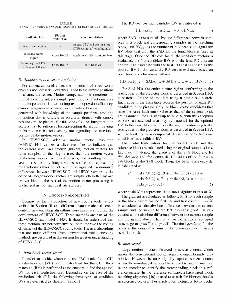
TABLE IITYPES OF CANDIDATE BVS AND ENCODER RESTRICTIONS ON THEIR USE
candidate BVs PU sizerestriction other restrictions
local search region – current CTU and one or moreCTUs to the left (configurable)
extended searchregion
up to 16×16 enable or disable (configurable)
Previously used BVswith same PU size
up to 16×16 up to 64 BVs
D. Adaptive motion vector resolution
For camera-captured video, the movement of a real-worldobject is not necessarily exactly aligned to the sample positionsin a camera’s sensor. Motion compensation is therefore notlimited to using integer sample positions, i.e. fractional mo-tion compensation is used to improve compression efficiency.Computer-generated screen content video, however, is oftengenerated with knowledge of the sample positions, resultingin motion that is discrete or precisely aligned with samplepositions in the picture. For this kind of video, integer motionvectors may be sufficient for representing the motion. Savingsin bit-rate can be achieved by not signalling the fractionalportion of the motion vectors.
In HEVC-SCC, adaptive motion vector resolution(AMVR) [44] defines a slice-level flag to indicate thatthe current slice uses integer (full-pel) motion vectors forluma samples. If the flag is true, then the motion vectorpredictions, motion vector differences, and resulting motionvectors assume only integer values, so the bits representingthe fractional values do not need to be signalled. To minimizedifferences between HEVC-SCC and HEVC version 1, thedecoded integer motion vectors are simply left-shifted by oneor two bits, so the rest of the motion vector processing isunchanged as the fractional bits are zero.
IV. ENCODING ALGORITHMS
Because of the introduction of new coding tools as de-scribed in Section III and different characteristics of screencontent, new encoding algorithms were introduced during thedevelopment of HEVC-SCC. These methods are part of theHEVC-SCC test model 3 [45]. It should be understood thatthese methods are not normative but help improve the codingefficiency of the HEVC-SCC coding tools. The new algorithmsthat are much different from conventional video encodingmethods are described in this session for a better understandingof HEVC-SCC.
A. Intra block vector search
In order to decide whether to use IBC mode for a CU,a rate-distortion (RD) cost is calculated for the CU. Blockmatching (BM) is performed at the encoder to find the optimalBV for each prediction unit. Depending on the size of theprediction unit (PU), the following three types of candidateBVs are evaluated as shown in Table II
The RD cost for each candidate BV is evaluated as:
RD costY = SADluma + λ× BVbits (4)
where SAD is the sum of absolute differences between sam-ples in a block and corresponding samples in the matchingblock, and BVbits is the number of bits needed to signal theBV. Note that only the SAD for the luma block is used atthis stage. Once the RD cost for all the candidate vectors isevaluated, the four candidate BVs with the least RD cost arechosen. The candidate with the best RD cost is chosen as theoptimal BV. In this case, the RD cost is evaluated based onboth luma and chroma as follows:
RD costYUV = SADluma + SADchroma + λ× BVbits (5)
For 8×8 PUs, the entire picture region conforming to therestrictions on the predictor block as described in Section III-Ais searched for the optimal BV using a hash-based search.Each node in the hash table records the position of each BVcandidate in the picture. Only the block vector candidates thathave the same hash entry value as that of the current blockare examined. For PU sizes up to 16×16, with the exceptionof 8×8, an extended area may be searched for the optimalBV. In this case, block vectors in the region conforming to therestrictions on the predictor block as described in Section III-Awith at least one zero component (horizontal or vertical) areconsidered as candidate BVs.
The 16-bit hash entries for the current block and thereference block are calculated using the original sample values.Let gradBLK denote the gradient of the 8×8 block and letdc0, dc1, dc2, and dc3 denote the DC values of the four 4×4sub-blocks of the 8×8 block. Then, the 16-bit hash entry His calculated as:
H = msb(dc0, 3)� 13 + msb(dc1, 3)� 10 +
msb(dc2, 3)� 7 + msb(dc3, 3)� 4 +
msb(gradBLK, 4) (6)
where msb(X,n) represents the n most significant bits of X .The gradient is calculated as follows: First for each sample
in the block except for the first line and first column, gradXis calculated as the absolute difference between the currentsample and the sample to the left. Similarly gradY is cal-culated as the absolute difference between the current sampleand the sample above. Then grad for the sample is set equalto average of gradX and gradY . The final gradBLK for theblock is the cumulative sum of the per-sample grad valuesover the block.
B. Inter search
Large motion is often observed in screen content, whichmakes the conventional motion search computationally pro-hibitive. However, because digitally-captured screen contentis usually noiseless, it is possible to use fast search methodsin the encoder to identify the corresponding block in a ref-erence picture. In the reference software, a hash-based blockmatching algorithm [46] is used to search for identical blocksin reference pictures. For a reference picture, a 16-bit cyclic

9
redundancy check (CRC) value is calculated using the originalsample values for a block starting from any sample positionand having sizes of 8× 8, 16× 16, 32× 32 and 64× 64. An18-bit hash value is formed comprising the 16-bit CRC and2 bits representing the block size. An inverted index is usedto index every block having the same hash value. For a CUwith a 2Nx2N prediction unit, the hash value is calculated,and with this hash value an exact match can be searched forusing the inverted index in linear time, regardless of the searchrange and number of reference pictures. To reduce the memoryrequirement for storing the hash table, a pre-filtering processis applied to exclude blocks that can be easily predicted usingintra prediction. For those blocks, it is not necessary to performblock matching. When a block cannot find an exact match inthe reference picture, as is the case for most camera-capturedmaterial, conventional motion estimation is used. For simplescreen content material, most blocks can have exact matches.Thus, the motion estimation search process is often be skipped,which can significantly reduce the encoding complexity.
C. Palette mode encoding
To evaluate the RD cost of encoding a CU in palette modea palette table for the CU is derived as follows. A modifiedk-means clustering method is used to derive a palette tablein the lossy case. The palette table is initialized to haveno entries. Then, for each sample in the CU, the nearestpalette entry (in terms of SAD) is determined. If the SADis within a threshold value, the sample is added to the clustercorresponding to the nearest palette entry. Otherwise a newpalette entry is created to be equal to the sample value. Afterprocessing all the samples in the CU, each palette entry isupdated by the centroid of the cluster. Then, the palette entriesare sorted based on the number of entries in their associatedclusters. There is a limit on the maximum palette size, whichis signalled in the sequence parameter set. If the number ofpalette entries exceeds this limit, the least frequent clusters areeliminated and the sample values belonging to those clustersare converted to escape samples.
As discussed in Section III-B, if a palette entry is alreadyin the palette predictor, the cost of including it in the currentpalette is small. On the other hand, when the centroid is not inthe palette predictor, all the components have to be signalledexplicitly in the bit-stream, resulting in much higher cost.Hence a rate distortion analysis is performed to determinewhether assigning a cluster to an existing palette predictorentry has a lower RD cost. If this is the case, then thecentroid is replaced by the palette predictor entry. After thisstep, duplicate palette entries are removed. Also, if a clusterincludes a single entry that is not contained in the palettepredictor, the entry is converted to an escape sample. Forlossless coding a slightly different method of palette derivationbased on histogram of the CU samples is used.
Once the palette table and assignment of CU sample valuesto palette indices are determined, a rate-based encoder opti-mization is performed to determine the palette run type flagand run values [47]. For example, assuming that index modeis chosen for the sample, a run value is determined. Then, the
per-sample cost in bits for coding the index and run value iscalculated. This cost is compared to the per-sample bit costfor coding the run value assuming COPY ABOVE MODE ischosen. The run type with the lower per-sample bit cost ischosen. The decision is greedy in the sense that sometimeswhen COPY ABOVE MODE is chosen, the cost of codingan index is just postponed to a future run. More sophisti-cated strategies are possible. For example, instead of firstperforming index assignment and then making the decisionabout palette run type flag and run values, it may be possibleto make these decisions jointly. As a simple example, byforcing a sample value to map to a different index, it maybe possible to extend a run, thereby lowering the RD cost.Such strategies are currently not considered in HEVC-SCCtest model 3 encoder.
D. Decision for adaptive colour transform
When the adaptive colour transform is enabled, a codingunit can choose to perform the colour transform describedin III-C on the residual of three colour components. In thecurrent test model, the encoder simply compares the R-D costsof coding in both modes (with or without the colour transform)and selects one with the least cost. Thus, the encoding timeincreases accordingly.
E. Decision for adaptive motion vector resolution
For each slice, an encoder can choose to use full-pel orfractional motion vectors for luma samples. In the current testmodel, instead of checking both options and comparing theRD costs, a fast algorithm is used to make the decision forthe entire slice. The basic idea of this algorithm is to determinewhether most blocks in the current slice have exact matchingblocks with full-pel displacements in the reference picture.
Similar to the inter search scheme described earlier, hashvalues are precomputed for every possible 8× 8 block in thereference picture. Next, the current slice is divided into non-overlapped 8 × 8 blocks. For each block, the correspondinghash value is calculated, and an exact match for each currentblock’s hash is searched for in the list of reference blockhashes, without considering the case of hash collision. A matchindicates that an integer motion vector would yield an exactmatch, without the need to actually perform the motion search.If exact matches are found for most of the 8 × 8 blocks,then full-pel motion vectors will be used for the slice. Forthe detailed algorithms, readers can refer to [44].
V. PERFORMANCE ANALYSIS
Simulations were conducted to evaluate the new cod-ing tools in HEVC-SCC and compare the coding effi-ciency of HEVC-SCC with HEVC-RExt and H.264/AVC. ForH.264/AVC, HEVC-RExt and HEVC-SCC, the reference soft-ware JM-18.6, HM-16.4 and SCM-3.0/SCM-4.0 were used,respectively.

10
A. Test conditions
The common test conditions (CTC) used during the devel-opment of HEVC-SCC [48] were used to generate the resultspresented in this section. These test conditions include videosequences comprising a variety of resolutions and contenttypes. Table III lists the 4:4:4 sequences. In the categorycolumn, ”TGM”, ”CC”, ”M” and ”A” stand for text andgraphics with motion, camera-captured content, mixed content(i.e. content having both TGM and CC) and animation. Foreach sequence, two colour formats are tested. One is in RGBand the other is in YCbCr, denoted as YUV in the tables).Table IV lists the 4:2:0 sequences. All of them are in YCbCrcolour format. As indicated by their names, several of the 4:2:0sequences are generated from their 4:4:4 correspondences.
TABLE IIITEST SEQUENCES (4:4:4) IN THE CTC.
Resolution Sequence name Category
1920x1080
sc flyingGraphics 1920x1080 60 8bit TGMsc desktop 1920x1080 60 8bit TGMsc console 1920x1080 60 8bit TGM
MissionControlClip3 1920x1080 60p 8b444 MEBURainFruits 1920x1080 50 10bit CC
Kimono1 1920x1080 24 10bit CC
1280x720
sc web browsing 1280x720 30 8bit TGMsc map 1280x720 60 8bit TGM
sc programming 1280x720 60 8bit TGMsc SlideShow 1280x720 20 8bit TGM
sc robot 1280x720 30 8bit A
2560x1440 Basketball Screen 2560x1440 60p 8b444 MMissionControlClip2 2560x1440 60p 8444 M
TABLE IVTEST SEQUENCES (4:2:0) IN THE CTC.
Resolution Sequence name Category
1920x1080
sc flyingGraphics 1920x1080 60 8bit 420 TGMsc desktop 1920x1080 60 8bit 420 TGMsc console 1920x1080 60 8bit 420 TGM
MissionControlClip3 1920x1080 60p 8b420 M
1280x720
sc web browsing 1280x720 30 8bit 420 r1 TGMsc map 1280x720 60 8bit 420 TGM
sc programming 1280x720 60 8bit 420 TGMsc SlideShow 1280x720 20 8bit 420 TGM
sc robot 1280x720 30 8bit 420 A
2560x1440 Basketball Screen 2560x1440 60p 8b420 MMissionControlClip2 2560x1440 60p 8420 M
1024x768 ChinaSpeed 1024x768 30 A
Three test configurations, i.e. all intra (AI), random access(RA) and low-delay B (LB) were used. For lossy coding, fourQPs, {22, 27, 32, 37}, were applied. More details can be foundin [48].
B. Performance analysis of coding tools
To verify the effectiveness of coding tools described inSection III, Tables V, VI, VII and VIII show the codingperformance compared to an anchor not having the specific
coding tool in SCM-3.0, for 4:4:4 sequences2. Only the BD-rate measures of the first colour component are listed due tospace limitations. From these tables, it can be seen that bothIBC and palette modes are very effective for videos in theTGM and M categories. For camera-captured content, bothtools neither help nor harm the coding efficiency noticeably.Another observation is that the coding gain for AI is largerthan that for RA or LB, because both IBC and palette modesare for intra coding.
From Table VII, it can be observed that ACT improves thecoding of RGB videos significantly, regardless of categories.In contrast, the performance gains of ACT are limited whenthe video is already in the YUV colour format.
TABLE VCOMPARISON OF SCM-3.0 WITH VERSUS WITHOUT IBC (BD-RATE
CHANGE).
AI RA LB
RGB
TGM -31.3% -19.1% -10.6%M -28.9% -19.2% -8.9%A -1.1% -0.5% -0.1%
CC -0.1% 0.0% 0.0%
YUV
TGM -32.5% -19.1% -9.8%M -29.5% -19.9% -8.9%A -1.6% -0.5% 0.1%
CC -0.2% 0.0% 0.1%
TABLE VICOMPARISON OF SCM-3.0 WITH VERSUS WITHOUT PALETTE (BD-RATE
CHANGE).
AI RA LB
RGB
TGM -15.5% -10.5% -6.8%M -3.7% -2.6% -1.5%A 0.0% -0.1% 0.0%
CC 0.0% 0.0% 0.0%
YUV
TGM -16.2% -11.1% -6.8%M -5.9% -4.4% -2.7%A 0.1% 0.2% 0.1%
CC 0.0% 0.1% 0.1%
TABLE VIICOMPARISON OF SCM-3.0 WITH VERSUS WITHOUT ACT (BD-RATE
CHANGE).
AI RA LB
RGB
TGM -9.6% -11.6% -11.1%M -16.6% -23.1% -23.7%A -24.5% -24.9% -24.0%
CC -24.5% -27.5% -26.1%
YUV
TGM -0.4% -0.7% -1.0%M 0.1% 0.4% 0.4%A 0.1% -0.1% 0.0%
CC 0.1% 0.5% 0.3%
2For individual tool comparisons, SCM-3.0 is used because it alreadycontains all coding tools mentioned above. The improvements of later versionsof SCM are mainly for 4:2:0 sequences.
11
TABLE VIIICOMPARISON OF SCM-3.0 WITH VERSUS WITHOUT AMVR (BD-RATE
CHANGE).
RA LB
RGB
TGM -1.4% -2.2%M 0.0% 0.0%A 0.0% 0.0%
CC 0.0% 0.0%
YUV
TGM -1.5% -2.4%M 0.0% -0.1%A 0.0% 0.0%
CC 0.0% 0.0%
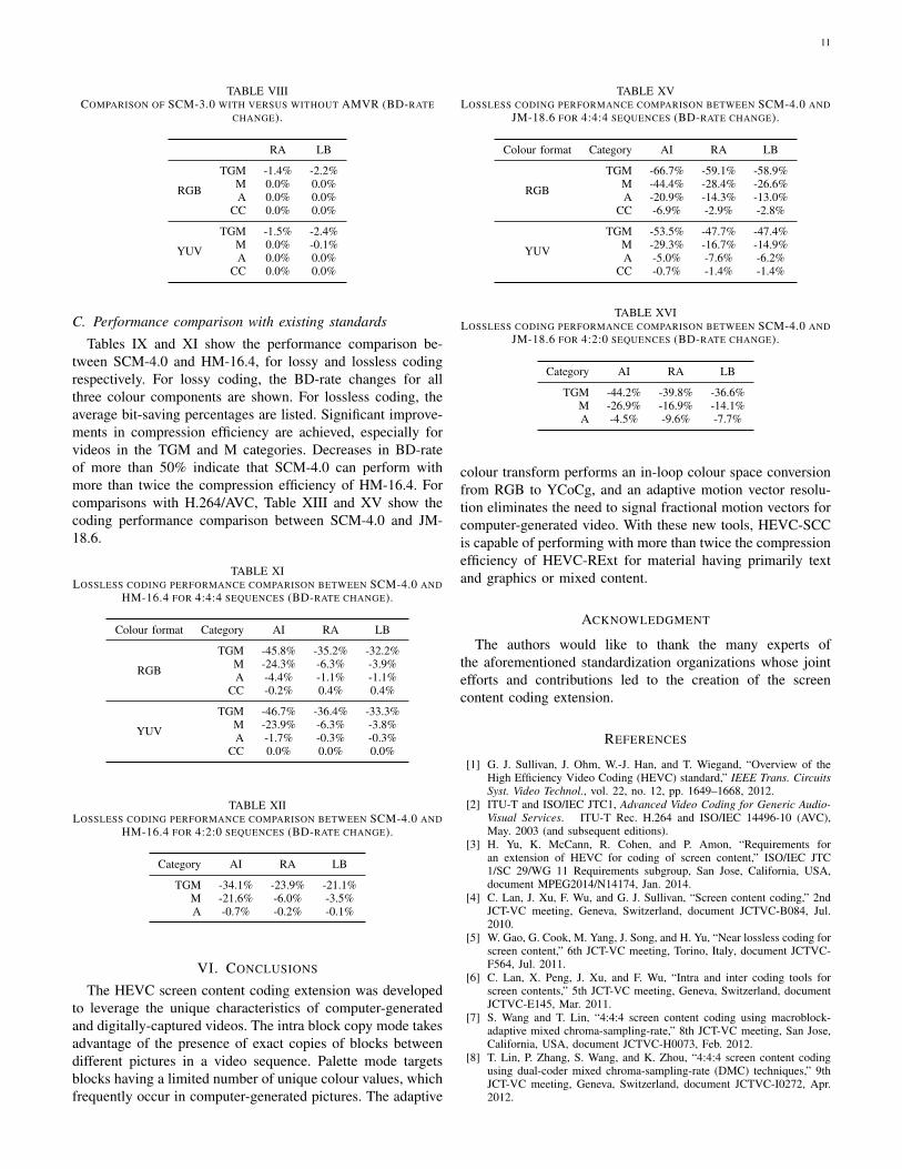
C. Performance comparison with existing standards
Tables IX and XI show the performance comparison be-tween SCM-4.0 and HM-16.4, for lossy and lossless codingrespectively. For lossy coding, the BD-rate changes for allthree colour components are shown. For lossless coding, theaverage bit-saving percentages are listed. Significant improve-ments in compression efficiency are achieved, especially forvideos in the TGM and M categories. Decreases in BD-rateof more than 50% indicate that SCM-4.0 can perform withmore than twice the compression efficiency of HM-16.4. Forcomparisons with H.264/AVC, Table XIII and XV show thecoding performance comparison between SCM-4.0 and JM-18.6.
TABLE XILOSSLESS CODING PERFORMANCE COMPARISON BETWEEN SCM-4.0 AND
HM-16.4 FOR 4:4:4 SEQUENCES (BD-RATE CHANGE).
Colour format Category AI RA LB
RGB
TGM -45.8% -35.2% -32.2%M -24.3% -6.3% -3.9%A -4.4% -1.1% -1.1%
CC -0.2% 0.4% 0.4%
YUV
TGM -46.7% -36.4% -33.3%M -23.9% -6.3% -3.8%A -1.7% -0.3% -0.3%
CC 0.0% 0.0% 0.0%
TABLE XIILOSSLESS CODING PERFORMANCE COMPARISON BETWEEN SCM-4.0 AND
HM-16.4 FOR 4:2:0 SEQUENCES (BD-RATE CHANGE).
Category AI RA LB
TGM -34.1% -23.9% -21.1%M -21.6% -6.0% -3.5%A -0.7% -0.2% -0.1%
VI. CONCLUSIONS
The HEVC screen content coding extension was developedto leverage the unique characteristics of computer-generatedand digitally-captured videos. The intra block copy mode takesadvantage of the presence of exact copies of blocks betweendifferent pictures in a video sequence. Palette mode targetsblocks having a limited number of unique colour values, whichfrequently occur in computer-generated pictures. The adaptive
TABLE XVLOSSLESS CODING PERFORMANCE COMPARISON BETWEEN SCM-4.0 AND
JM-18.6 FOR 4:4:4 SEQUENCES (BD-RATE CHANGE).
Colour format Category AI RA LB
RGB
TGM -66.7% -59.1% -58.9%M -44.4% -28.4% -26.6%A -20.9% -14.3% -13.0%
CC -6.9% -2.9% -2.8%
YUV
TGM -53.5% -47.7% -47.4%M -29.3% -16.7% -14.9%A -5.0% -7.6% -6.2%
CC -0.7% -1.4% -1.4%
TABLE XVILOSSLESS CODING PERFORMANCE COMPARISON BETWEEN SCM-4.0 AND
JM-18.6 FOR 4:2:0 SEQUENCES (BD-RATE CHANGE).
Category AI RA LB
TGM -44.2% -39.8% -36.6%M -26.9% -16.9% -14.1%A -4.5% -9.6% -7.7%
colour transform performs an in-loop colour space conversionfrom RGB to YCoCg, and an adaptive motion vector resolu-tion eliminates the need to signal fractional motion vectors forcomputer-generated video. With these new tools, HEVC-SCCis capable of performing with more than twice the compressionefficiency of HEVC-RExt for material having primarily textand graphics or mixed content.
ACKNOWLEDGMENT
The authors would like to thank the many experts ofthe aforementioned standardization organizations whose jointefforts and contributions led to the creation of the screencontent coding extension.
REFERENCES
[1] G. J. Sullivan, J. Ohm, W.-J. Han, and T. Wiegand, “Overview of theHigh Efficiency Video Coding (HEVC) standard,” IEEE Trans. CircuitsSyst. Video Technol., vol. 22, no. 12, pp. 1649–1668, 2012.
[2] ITU-T and ISO/IEC JTC1, Advanced Video Coding for Generic Audio-Visual Services. ITU-T Rec. H.264 and ISO/IEC 14496-10 (AVC),May. 2003 (and subsequent editions).
[3] H. Yu, K. McCann, R. Cohen, and P. Amon, “Requirements foran extension of HEVC for coding of screen content,” ISO/IEC JTC1/SC 29/WG 11 Requirements subgroup, San Jose, California, USA,document MPEG2014/N14174, Jan. 2014.
[4] C. Lan, J. Xu, F. Wu, and G. J. Sullivan, “Screen content coding,” 2ndJCT-VC meeting, Geneva, Switzerland, document JCTVC-B084, Jul.2010.
[5] W. Gao, G. Cook, M. Yang, J. Song, and H. Yu, “Near lossless coding forscreen content,” 6th JCT-VC meeting, Torino, Italy, document JCTVC-F564, Jul. 2011.
[6] C. Lan, X. Peng, J. Xu, and F. Wu, “Intra and inter coding tools forscreen contents,” 5th JCT-VC meeting, Geneva, Switzerland, documentJCTVC-E145, Mar. 2011.
[7] S. Wang and T. Lin, “4:4:4 screen content coding using macroblock-adaptive mixed chroma-sampling-rate,” 8th JCT-VC meeting, San Jose,California, USA, document JCTVC-H0073, Feb. 2012.
[8] T. Lin, P. Zhang, S. Wang, and K. Zhou, “4:4:4 screen content codingusing dual-coder mixed chroma-sampling-rate (DMC) techniques,” 9thJCT-VC meeting, Geneva, Switzerland, document JCTVC-I0272, Apr.2012.

12
TABLE IXLOSSY CODING PERFORMANCE COMPARISON BETWEEN SCM-4.0 AND HM-16.4 FOR 4:4:4 SEQUENCES (BD-RATE CHANGE).
AI RA LBColour format Category G/Y B/U R/V G/Y B/U R/V G/Y B/U R/V
RGB
TGM -64.5% -60.9% -62.0% -56.9% -51.0% -53.1% -50.8% -42.9% -45.3%M -54.8% -49.7% -49.5% -50.2% -42.4% -42.0% -41.7% -29.2% -28.2%A -26.3% -19.5% -16.8% -26.2% -17.3% -12.9% -24.4% -11.9% -5.5%
CC -25.6% -5.5% -10.4% -28.3% -5.8% -14.4% -26.1% -1.6% -11.9%
YUV
TGM -57.4% -61.3% -62.8% -48.0% -52.6% -55.3% -40.5% -44.9% -47.4%M -45.2% -50.9% -50.8% -36.7% -45.1% -44.8% -23.8% -33.6% -33.3%A -1.2% -10.9% -7.6% -0.4% -10.1% -6.8% 0.0% -7.0% -4.9%
CC 0.4% 0.0% -0.2% 0.6% -0.2% -0.3% 0.6% -0.3% -0.2%
TABLE XLOSSY CODING PERFORMANCE COMPARISON BETWEEN SCM-4.0 AND HM-16.4 FOR 4:2:0 SEQUENCES (BD-RATE CHANGE).
AI RA LBCategory G/Y B/U R/V G/Y B/U R/V G/Y B/U R/V
TGM -49.0% -49.3% -50.5% -39.4% -40.6% -42.2% -32.7% -33.2% -34.4%M -36.6% -37.6% -37.6% -29.4% -31.2% -31.5% -18.0% -18.7% -19.5%A -7.3% -11.7% -10.7% -3.8% -12.4% -9.9% -2.0% -8.2% -5.7%
TABLE XIIILOSSY CODING PERFORMANCE COMPARISON BETWEEN SCM-4.0 AND JM-18.6 FOR 4:4:4 SEQUENCES (BD-RATE CHANGE).
AI RA LBColour format Category G/Y B/U R/V G/Y B/U R/V G/Y B/U R/V
RGB
TGM -86.1% -83.5% -84.1% -80.4% -76.1% -77.4% -77.7% -73.0% -74.4%M -80.1% -76.2% -76.0% -74.3% -68.2% -67.3% -69.7% -60.8% -59.8%A -52.4% -45.0% -40.1% -54.8% -49.5% -43.2% -56.4% -51.0% -43.1%
CC -58.4% -35.6% -44.3% -63.3% -42.6% -51.5% -60.1% -36.5% -48.2%
YUV
TGM -74.6% -75.0% -77.0% -68.1% -70.4% -73.3% -65.4% -67.6% -70.5%M -63.6% -64.8% -64.8% -56.9% -63.2% -63.1% -51.5% -60.5% -60.6%A -23.4% -35.5% -29.3% -32.2% -48.0% -41.8% -39.0% -59.6% -54.6%
CC -26.5% -18.5% -25.4% -40.0% -42.2% -42.6% -39.8% -51.5% -53.6%
TABLE XIVLOSSY CODING PERFORMANCE COMPARISON BETWEEN SCM-4.0 AND JM-18.6 FOR 4:2:0 SEQUENCES (BD-RATE CHANGE).
AI RA LBCategory G/Y B/U R/V G/Y B/U R/V G/Y B/U R/V
TGM -69.9% -64.4% -65.3% -62.3% -61.6% -62.6% -60.3% -58.7% -59.5%M -57.4% -52.2% -53.1% -51.8% -51.7% -52.7% -47.0% -46.0% -47.7%A -31.7% -33.3% -33.5% -36.4% -45.2% -44.2% -39.5% -45.0% -43.9%
[9] ISO/IEC JTC1/SC29/WG11, “Joint call for proposals for codingof screen content,” ITU-T Q6/16 Visual Coding and ISO/IECJTC1/SC29/WG11 Coding of Moving Pictures and Audio, San Jose,California, USA, document MPEG2014/N14175, Jan. 2014.
[10] R. Joshi and J. Xu, “HEVC Screen Content Coding Draft Text 1,” 18thJCT-VC meeting, Sapporo, Japan, document JCTVC-R1005, Jul. 2014.
[11] ——, “HEVC Screen Content Coding Draft Text 2,” 19th JCT-VCmeeting, Strasbourg, France, document JCTVC-S1005, Nov. 2014.
[12] J. Boyce, J. Chen, Y. Chen, D. Flynn, M. M. Hannuksela, M. Naccari,C. Rosewarne, K. Sharman, J. Sole, G. J. Sullivan, T. Suzuki, G. Tech,Y.-K. Wang, K. Wegner, and Y. Ye, “Edition 2 Draft Text of HighEfficiency Video Coding (HEVC), Including Format Range (RExt),Scalability (SHVC), and Multi-View (MV-HEVC) Extensions,” 18thJCT-VC meeting, Sapporo, Japan, document JCTVC-R1013, Jul. 2014.
[13] M. Narroschke, “Extending H.264/AVC by an adaptive coding of theprediction error,” in Picture Coding Symposium, PCS2006, Beijing,China, Apr. 2006.
[14] C. Lan, J. Xu, G. J. Sullivan, and F. Wu, “Intra transform skipping,” 9thJCT-VC meeting, Geneva, Switzerland, document JCTVC-I0408, Apr.2012.
[15] X. Peng, C. Lan, J. Xu, and G. J. Sullivan, “Inter transform skipping,”10th JCT-VC meeting, Stockholm, Sweden, document JCTVC-I0408,Jul. 2012.
[16] R. Cohen and A. Vetro, “AHG8: Impact of transform skip on newscreen content material,” 12th JCT-VC meeting, Geneva, Switzerland,document JCTVC-L0428, Jan. 2013.
[17] X. Peng, J. Xu, L. Guo, J. Sole, and M. Karczewicz, “Non-RCE2:Transform skip on large TUs,” 14th JCT-VC meeting, Vienna, Austria,document JCTVC-N0288, Jul. 2013.
[18] J. An, L. Zhao, Y.-W. Huang, and S. Lei, “Residue scan for intratransform skip mode,” 10th JCT-VC meeting, Stockholm, Sweden,document JCTVC-J0053, Jun. 2012.
[19] D. He, J. Wang, and G. Martin-Cocher, “Rotation of residual blockfor transform skipping,” 10th JCT-VC meeting, Stockholm, Sweden,document JCTVC-J0093, Jun. 2012.
[20] X. Peng, B. Li, and J. Xu, “On residual rotation for inter and intra bcmodes,” 15th JCT-VC meeting, Geneva, Switzerland, document JCTVC-O0186, Oct. 2013.
[21] S. L. an I.-K. Kim and C. Kim, “AHG7: Residual DPCM for HEVClossless coding,” 12th JCT-VC meeting, Geneva, Switzerland, document
13
JCTVC-L0117, Jan. 2013.[22] R. Joshi, J. Sole, and M. Karczewicz, “AHG8: Residual DPCM for visu-
ally lossless coding,” 13th JCT-VC meeting, Incheon, Korea, documentJCTVC-M0351, Apr. 2013.
[23] M. Naccari, M. Mrak, A. Gabriellini, S. Blasi, and E. Izquierdo, “Inter-prediction residual DPCM,” 13th JCT-VC meeting, Incheon, Korea,document JCTVC-M0442, Apr. 2013.
[24] T. Nguyen, A. Khairat, and D. Marpe, “Non-RCE1/Non-RCE2/AHG5/AHG8: Adaptive Inter-Plane Prediction for RGBContent,” 13th JCT-VC meeting, Incheon, Korea, document JCTVC-M0230, Apr. 2013.
[25] X. Zhang, C. Gisquet, E. Francois, F. Zou, and O. C. Au, “Chroma intraprediction based on inter-channel correlation for HEVC,” IEEE Trans.Image Process., vol. 23, no. 1, pp. 274–286, Jan 2014.
[26] M. Karczewicz, L. Guo, J. Sole, R. Joshi, K. Sharman, N. Saunders, andJ. Gamei, “RCE2: Results of Test D1 on Rice Parameter Initialization,”15th JCT-VC meeting, Geneva, Switzerland, document JCTVC-O0239,Oct. 2013.
[27] D. Marpe, H. Kirchhoffer, V. George, P. Kauff, and T. Wiegand,“Macroblock-adaptive residual color space transforms for 4:4:4 videocoding,” in Image Processing, 2006 IEEE International Conference on,Atlanta, Georgia, USA, Oct. 2006.
[28] S. L. Yu and C. Chrysafis, “New intra prediction using intra-macroblockmotion compensation,” 3rd JVT meeting, Fairfax, Virginia, USA, doc-ument JVT-C151r1, May 2002.
[29] D.-K. Kwon and M. Budagavi, “AHG8: Video coding using intra mo-tion compensation,” 13th JCT-VC meeting, Incheon, Korea, documentJCTVC-M0350, Apr. 2013.
[30] C. Pang, J. Sole, L. Guo, M. Karczewicz, and R. Joshi, “Non-RCE3:Intra motion compensation with 2-D MVs,” 14th JCT-VC meeting,Vienna, Austria, document JCTVC-N0256, Jul. 2013.
[31] B. Li and J. Xu, “Non-SCCE1: Unification of intra BC and inter modes,”18th JCT-VC meeting, Sapporo, Japan, document JCTVC-R0100, Jul.2014.
[32] C. Pang, Y.-K. Wang, V. Seregin, K. Rapaka, M. Karczewicz, X. Xu,S. Liu, S. Lei, B. Li, and J. Xu, “CE2 Test1: Intra block copy andinter signalling unification,” 20th JCT-VC meeting, Geneva, Switzerland,document JCTVC-T0094, Feb. 2015.
[33] L. Guo, J. Sole, and M. Karczewicz, “Palette Mode for Screen ContentCoding,” 13th JCT-VC meeting, Incheon, Korea, document JCTVC-M0323, Apr. 2013.
[34] P. Onno, X. Xiu, Y.-W. Huang, and R. Joshi, “Suggested combinedsoftware and text for run-based palette mode,” 18th JCT-VC meeting,Sapporo, Japan, document JCTVC-M0348, Jul. 2014.
[35] Wikipedia, “Truncated binary encoding — Wikipedia, the freeencyclopedia,” 2014. [Online]. Available: http://en.wikipedia.org/wiki/Truncated binary encoding
[36] H. S. Malvar, G. J. Sullivan, and S. Srinivasan, “Lifting-basedreversible color transformations for image compression,” in SPIEApplications of Digital Image Processing. International Societyfor Optical Engineering, August 2008. [Online]. Available: http://research.microsoft.com/apps/pubs/default.aspx?id=102040
[37] L. Zhang, J. Chen, J. Sole, M. Karczewicz, X. Xiu, Y. He, andY. Ye, “SCCE5 Test 3.2.1: In-loop color-space transform,” 18th JCT-VC meeting, Sapporo, Japan, document JCTVC-R0147, July 2014.
[38] B. Li and J. Xu, “Fix for adaptive color space coding in JCTVC-Q0035,”17th JCT-VC meeting, Valencia, Spain, document JCTVC-Q0213, Mar.2014.
[39] L. Zhang, J. Chen, M. Karczewicz, B. Li, and J. Xu, “Unification ofcolour transforms in ACT,” 19th JCT-VC meeting, Strasbourg, France,document JCTVC-S0254, Oct. 2014.
[40] A. Khairat, T. Nguyen, M. Siekmann, D. Marpe, and T. Wiegand, “Adap-tive cross-component prediction for 4:4:4 high efficiency video coding,”in Image Processing (ICIP), 2014 IEEE International Conference on,Paris, France, Oct 2014.
[41] T. Nguyan, J. Sole, and J. Kim, “RCE1: Summary report of HEVCrange extensions core experiment 1 on inter-component decorrelationmethods,” 14th JCT-VC meeting, Vienna, Austria, document JCTVC-N0034, Jul. 2013.
[42] L. Zhang, J. Chen, J. Sole, M. Karczewicz, X. Xiu, and X. J., “Adaptivecolor-space transform for HEVC screen content coding,” in Data Com-pression Conference (DCC), 2015, Snowbird, Utah, USA, Apr. 2015.
[43] P. Lai, S. Liu, and S. Lei, “AHG6: On adaptive color transform (ACT) inSCM2.0,” 19th JCT-VC meeting, Strasbourg, France, document JCTVC-S0100, Nov. 2014.
[44] B. Li, J. Xu, G. Sullivan, Y. Zhou, and B. Lin, “Adaptive motionvector resolution for screen content,” 19th JCT-VC meeting, Strasbourg,France, document JCTVC-S0085, Oct. 2014.
[45] R. Joshi, J. Xu, C. R., S. Liu, Z. Ma, and Y. Ye, “Screen Content CodingTest Model 3 Encoder Description (SCM 3),” 19th JCT-VC meeting,Strasbourg, France, document JCTVC-S1014, Oct. 2014.
[46] B. Li, J. Xu, F. Wu, X. Guo, and G. J. Sullivan, “Description ofscreen content coding technology proposal by Microsoft,” 17th JCT-VCmeeting, Valencia, Spain, document JCTVC-Q0035, Mar. 2014.
[47] W. Pu, F. Zou, V. Seregin, R. Joshi, M. Karczewicz, and J. Sole, “Non-CE6: Palette parsing dependency and palette encoder improvement,”19th JCT-VC meeting, Strasbourg, France, document JCTVC-S0156,Oct. 2014.
[48] H. Yu, R. Cohen, K. Rapaka, and J. Xu, “Common test conditions forscreen content coding,” 20th JCT-VC meeting, Geneva, Switzerland,document JCTVC-T1015, Feb. 2015.
Jizheng Xu (M’07-SM’10) received the B.S. andM. S. degrees in computer science from the Univer-sity of Science and Technology of China (USTC),and the Ph.D. degree in electrical engineering fromShanghai Jiaotong University, China.
He joined Microsoft Research Asia (MSRA) in2003 and currently he is a Lead Researcher. Hehas authored and co-authored over 100 conferenceand journal refereed papers. He has over 30 U.S.patents granted or pending in image and videocoding. His research interests include image and
video representation, media compression, and communication. He has beenan active contributor to ISO/MPEG and ITU-T video coding standards. Hehas over 30 technical proposals adopted by H.264/AVC, H.264/AVC scalableextension, High Efficiency Video Coding, HEVC range extension and HEVCscreen content coding standards. He chaired and co-chaired the ad-hoc groupof exploration on wavelet video coding in MPEG, and various technical ad-hocgroups in JCT-VC, e.g., on screen content coding, on parsing robustness, onlossless coding. He co-organized and co-chaired special sessions on scalablevideo coding, directional transform, high quality video coding at variousconferences. He also served as special session co-chair of IEEE InternationalConference on Multimedia and Expo 2014.
Rajan Joshi (M’95) received the the B. Tech. degreein electrical engineering and the M. Tech. degree incommunications engineering from Indian Institute ofTechnology, Mumbai in 1988 and 1990, respectively,and the Ph.D. degree in electrical engineering fromWashington State University, Pullman, WA, in 1996.
In 1995, he was with the Xerox Palo Alto Re-search Center, Palo Alto, CA. From 1996 to 2006 hewas a Senior Research Scientist with Eastman KodakCompany, in Rochester, NY. From 2006 to 2008, hewas a Senior Member Technical Staff with Thomson
Corporate Research in Burbank, CA. He joined Qualcomm, Inc. in SanDiego, CA, in 2008, where he is currently a Senior Staff Engineer/Manager.He has been an active participant in several past and present video andimage coding standardization efforts such the Joint Collaborative Team onVideo Coding (JCT-VC) for the development of the HEVC standard, andits extensions, JPEG2000, and the advanced display stream compression taskgroup in VESA. His current research interests include video and image coding,video processing, and information theory.

14
Robert A. Cohen (S’85-M’90-SM’12) received theB.S. (summa cum laude) and M.Eng. in computerand systems engineering, and in 2007 the Ph.D.degree in electrical engineering from RensselaerPolytechnic Institute, Troy, NY. While a student,he held positions at IBM and at Harris RF Com-munications. From 1991 to 2001, he was a seniormember of the research staff in Philips Research,Briarcliff Manor, NY, where he performed researchin areas related to the Grand Alliance HDTV de-coder, rapid prototyping for VLSI video systems,
statistical multiplexing for digital video encoders, scalable MPEG-4 videostreaming, and next-generation video surveillance systems. Since 2007 he hasbeen a principal member of the research staff at Mitsubishi Electric ResearchLaboratories (MERL) in Cambridge, MA, where he performs research,publishes, and generates patents related to next-generation video coding,screen-content coding, and perceptual image/video coding and processing.He also actively participates in ISO/MPEG and ITU standardization activities,including chairing several ad hoc groups and core experiments, contributingto HEVC-related call for proposals and drafting the Joint Call for Proposalsfor coding of screen content in JCT-VC. Recently he organized the specialsession on screen content coding in PCS 2013, and he was a guest editor ofthe Signal Processing: Image Communication Special issue on advances inhigh dynamic range video research. His current research interests are videocoding & communications, video, image & signal processing, and 3D pointcloud compression.