overview of super-harvard architecture (sharc) daniel glickdaniel glick – may 15, 2002 for...
TRANSCRIPT

Overview of Super-Harvard Architecture (SHARC)
Daniel Glick – May 15, 2002for V22.0480-002 (Dewar)

SHARC
32-bit DSPOptimized for I/O – DMA, rapid interrupt handling, dual-ported memoryOn-board floating point
We will examine ADSP-2106xManuals are online at:http://www.analog.com/library/dspManuals/ADSP_2106x_SHARC_Users_Manual_books.html

Registers – General RegistersRegister file
16 40-bit registersEach register can be interpreted as fixed point (R prefix) or floating point (F prefix)Divided into two segments for context switching
Multiplier result register80 bits, accessible as three 32-bit registers

Registers – Addressing Registers16 sets of addressing registers, divided into 4 segments for context switchingEach set has:
IndexModifier (offset from index)Base (base of circular buffer)Length (length of circular buffer)

Registers – System RegistersProgram Sequencer Registers
3 program counters (1 for each stage of pipeline)5 registers for branching (subroutines and looping)
System Registers2 32-bit mode registers3 registers for interrupt handlingFlags

Registers - FlagsArithmetic status flag registers
ASTAT: reset after each operationSTKY: remains set until clearedSame registers, different semantics for:
ALU ops Multiplier ops Shifter ops
Two user-defined 32-bit status registers

Registers – Context SwitchingAlternate set of general, multiplier, and address registersEach segment of registers can be separately switched between primary/alternate sets by setting a bit in the mode register

Data Formats
Integer32-bit word
In 40-bit register, stored in 32 MSBs
Floating-point32-bit (IEEE standard)40-bit (IEEE + 8 extra LSBs of mantissa)16-bit (11-bit mantissa + 5-bit exponent + sign bit)

Memory - AddressingWord-based addressing
16, 32, or 48-bit words
Two address busesData bus: 32-bit addressesProgram bus: 24-bit addresses
Can also be used to access data
Each bus has a Data Address Generator (DAGs)

Memory – Addressing (cont.)Each DAG has eight sets of registers
Each set is: Index, Modifer, Base, and Length
Addressing modes:Index + modifierIndex + immediate(Index + modifier mod length) + base
For circular buffers
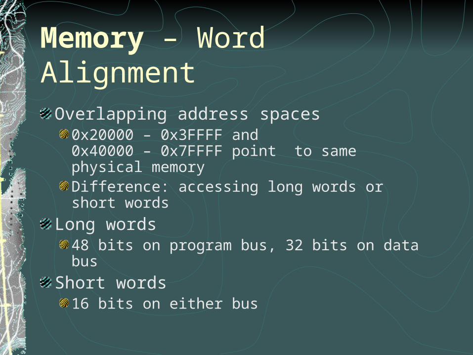
Memory – Word AlignmentOverlapping address spaces
0x20000 – 0x3FFFF and0x40000 – 0x7FFFF point to same physical memoryDifference: accessing long words or short words
Long words48 bits on program bus, 32 bits on data bus
Short words16 bits on either bus

Memory – Physical StructureUp to 512 KB of on-chip SRAM
Divided into two equal-sized blocks Both can be accessed simultaneously, using both buses
External Memory32-bit addressesUp to 4 gigawords

Instruction Set – Compute & MoveArithmetic, multiple, shift, register move, load, storeLoads and stores can be explicit or part of a compute operationExecution of each instruction can be conditioned on a flag

Instruction Set – Flow ControlJUMP and CALL to relative or absolute address
Can be conditioned on flags Compute instruction can be conditioned on failure of jump
condition, all within a single instruction word
CALLs and interrupts store return address to on-chip PC Stack
30 levels deepTriggers interrupt when 29 levels full

Instruction Set – Flow Control (cont)
DO UNTIL – loopingCondition can be flagCondition can be loop counter register = 0
Loop stacks, for nested loopsLoop counter stackLoop termination address stackBoth 6 levels deep

Instruction Set – Multiple ComputeDual add / subtract
Dual-result op: sum and difference of input regsParallel multiply / ALU
Simultaneously performs multiplication and ALU operation
All multiple compute ops limited to a specific subset of registers, to fit within 48-bit instruction word

Instruction Set - MiscellaneousSet register bitsAccess flow control stacksIDLE: halt until interruptFlush instruction cacheCJUMP/RFRAME
C-style function prolog and epilog

Pipelining & Caching
Three-stage pipelineFetchDecodeExecute
2-way, set-associative, 32-instruction cacheInstructions are only cached if they conflict with a data read

Instruction Latency
One cycle latency on register context switchOne cycle latency on some writes to system registersDelay flag in branch instructions
If set, two instructions following branch are executed
Loop exit testTest value must be set two cycles before test
Interrupts
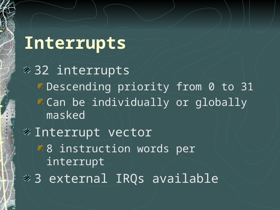
32 interruptsDescending priority from 0 to 31Can be individually or globally masked
Interrupt vector8 instruction words per interrupt
3 external IRQs available

Interrupts - HandlingInterrupt is latched during processing
Cannot be re-triggered until processing is overFor some interrupts, status and mode flags are stored to on-chip status stackBased on system option flag:
Either all interrupts are maskedOr all lower-priority interrupts are masked
Latency: for most interrupts, one instruction is executed after interrupt triggered

I/O
DMA10 channelsFor each channel, three memory-mapped registers:
II – starting address base IM – starting address modifier C – number of words to transfer
Interrupts at end of transfer (C = 0)

Summary – Design PhilosophyCISC/RISC hybrid
PipelinedFixed-width instructionsSome instructions are complex, multi-cycle
Efficiency chosen over consistency/simplicitySpecial instructionsSpecialized registersNo consistent word sizeSpecialized buses