overview of new design - engr.psu.edu · the new design for the hyatt tower is structural steel...
TRANSCRIPT

����������� �� �������� ������
��������������� ����������������������� �������
� �������������
�
18
Another design criterion that must be followed is the layout of the floor plans. In similar conversation with the design architects, the Global Hyatt Corporation has set criteria for general building design. In order to prevent architectural conflict, the new design will try to constrain to architectural layout with any variations noted in the conclusions. Overview of New Design The new design for the Hyatt tower is structural steel framing with symmetrically placed chevron braced frames to resist lateral loads. The preliminary design compared similar systems to determine the most viable option for a full new design. Various non-composite and composite steel floor systems were compared to select the primary system used in typical bays in the new design. Non-composite systems were analyzed with 4’-0”, 4’-6”, and 5’-0” beam spacing in both typical bay sizes: 24’-0” x 27’-0” and 18’-6” x 27’-0”. All non-composite designs resulted in deep sections (compared to the existing 8” filigree slab). Composite systems were then analyzed to determine the feasibility of composite steel framing. With the use of W8x48 beams and composite action, the total floor depth was increased to 12”, significantly smaller than the 14” depth of typical non-composite configurations. Using the composite floor framing, preliminary sizes were found for beams and columns. A computer model was created in RAM Structural Systems to assist in calculations and distribution of loads. Using code specified loads and load cases; the new structure was designed. Braced frames were selected to prevent greatly increasing member sizes through the use of moment frames.
Member sizes of beams, columns, and braces were edited to reduce moment-axial interaction to levels below 95% of allowable interaction. In addition, member sizes were standardized throughout the design to minimize the number of different sections used and create more typical framing. Column splices were placed every 3 levels (main level counted as 2 levels due to increased height).
New seismic and wind loads are compared to the original loads on the original design to compare the effects of the new design on the loading. The seismic loading decreased significantly with the significant decrease in building weight, while wind loads increase slightly based on the small increase of building height.
A vibration analysis has been calculated to determine the impact of walking
induced vibrations in guest rooms based on the excitation force from the corridors. This check determines whether or not the lighter framing could cause serviceability issues for guests.

����������� �� �������� ������
��������������� ����������������������� �������
� �������������
�
19
In accordance with IBC 2003 LRFD design, the following factored load cases were considered for the new design:
• 1.4 D • 1.2 D + 1.6 L • 1.2 D ± 1.6 W + 0.5 L • 1.2 D ± 1.0 E + 0.5 L • 0.9 D ± (1.6 W or 1.0 E)
D = dead load or dead load effects L = live load or live load effects W = wind load or wind load effects E = seismic load or seismic load effects
Gravity Load Design The new gravity design was achieved through a process of comparing various alternate floor framing systems and choosing the system that would best fit the criteria for the new design. As the floor to floor height would greatly impact the overall height of the building, which is a major design criterion to be met, the new gravity system would need to be designed to provide the necessary strength to resist the gravity loads as well as having a relatively small depth. The initial framing choices were compared to the initial filigree system to determine which would be the best choice for the new design. The major three steel framing systems investigated were: open-web steel joists with steel beams, non-composite steel beams and girders, and composite steel beams and girders. Through investigation of various spacing of the members, the depths of the systems were roughly determined. Through open-web steel joists with 16K5 at 2’-0” on center, with 2.5” slab thickness; total floor depth was 18.5”. The non-composite W10X49 at 6’-0” on center, with 3.5” slab thickness; total floor depth was 13.5”. The composite W8X48 at 8’-0” on center, with 3.5” slab thickness; total floor depth 12”. See Appendix C for calculations. Although the 12” depth is still greatly increased from the filigree slab thickness of 8”, the composite system was the best choice for the framing. Although it may be possible to decrease the floor depth slightly by decreasing the beam spacing, it would be a less efficient floor system. In addition, based on deck spans and beam depths, it is unlikely that a composite system could be found that would decrease the depth of the floor much more than the 12” depth found. In addition, AISC shear connections require a minimum 2-bolt connection; with a 3” bolt spacing and ¾” A325-N bolts, this would require a web depth (minus flange thickness) of at least 5.5”, which is within the range of

����������� �� �������� ������
��������������� ����������������������� �������
� �������������
�
20
W8 sections. Smaller members would prove both inefficient and may not even be feasible under standard construction practices. While the composite system may increase the labor costs for the installation of the shear studs, the more critical design criterion of preventing the building height from significantly increasing is a more critical factor in the consideration of the system. Bay sizes are typical in the tower with 27’-0” x 18’-6” exterior bays and 27’-0” x 24’-0” interior bays. Beams were selected to span 27’ in both bays with girders running perpendicular. The selection was made so that the girders would be spanning shorter distances than the beams that they support. This selection was made so that the girders would be located above the partition walls between guest rooms, where the depth of the members was less critical. In exterior bays, beam spacing was selected to have 2 equal spaces, or 9’-3” center-to-center spacing of the beams; exterior girders span 18’-6” between columns. In interior bays, beam spacing was selected to have 3 equal spaces, or 8’-0” center-to-center spacing of the beams; interior girders span 24’-0” between columns. Gravity column sizes were initially selected from hand calculations (See Appendix D) by determining accumulated gravity loads below levels 2, 8, and 12 of typical interior and exterior columns. This allowed an approximate design size to be compared to initial computer design sizes to ensure that loads were being accounted for properly. Live load reduction on the non-roof levels was taken into account as the live loads were not greater than 100 psf and met other criteria for reduction according to ASCE 7-02. W14 sections were chosen for the initial selection as they are easy to stack and are commonly used for columns in professional practice. Initial member sizes selected for the columns below level 2 are W14X48; below level 8 are W14X53 exterior and W14X109 interior; and below level 12 are W14X74 exterior and W14X145 interior. Once the initial sizes were determined from hand calculations, a computer model was created in RAM Structural Systems for analysis and further member design. Since member depth was of great concern, after initial computer sizing calculations, member sizes were manually overridden to match those that were determined by hand calculations. Computer checks of the updated model showed that the member sizes selected through hand calculations were suitable for design, although they were not the optimized member sizes selected through the RAM calculations. Since the members selected have a smaller depth than the optimized sections, some of the members require a camber to meet deflection criteria of �/360 for live loads and �/240 for dead plus live loads. The following page contains floor plans for the West (Figure 13) and East (Figure 14) ends of the tower with new steel framing member sizes shown. In addition, required cambers and shear studs requirements are detailed on the plan.

����������� �� �������� ������
��������������� ����������������������� �������
� �������������
�
21
Figure 13. – Layout of New Floor Plan (Tower – West End)
Figure 14. – Layout of New Floor Plan (Tower – East End)

����������� �� �������� ������
��������������� ����������������������� �������
� �������������
�
22
With the increased depth, the floor-to-floor story height was changed from 10’ to 11’ in levels 2 through the roof to accommodate the increased member depth as well as allow for an architectural ceiling to be added below the new steel framing. This would have the effect of adding 10’ to the total building height. While this is a significant increase, with larger member sizing (even only 13.5” floor depth), over 10 stories, the building height increases 1 foot per 1.2” of depth added to the section. The 10’ increase in height was determined to be acceptable, as it is less than a 10% increase in the total height of the building. (While this may not be acceptable for the airport restrictions, for the purpose of analysis and comparison, the change will be considered acceptable) If the building height would be required to be decreased based on the new design, the height of the main level that houses the lobby could be decreased to accommodate the changes, or the building could be adjusted to have the ground level start at a lower overall elevation. With the minimal change in height, any problems arising could easily be resolved with minor architectural changes that would not affect the guest rooms in the tower. Columns splices were set every 3 stories. Column schedule and plans below:
Figure 15. – Gravity Column Schedule (See plans, next page, for location)

����������� �� �������� ������
��������������� ����������������������� �������
� �������������
�
23
Figure 16. – Layout of Columns (Tower – East End)
Figure 17. – Layout of Columns (Tower – East End)

����������� �� �������� ������
��������������� ����������������������� �������
� �������������
�
24
Lateral Load Design
The lateral load resisting system for the new design must be adequate to resist the design load combinations. The loads have been calculated for wind design based on the ASCE 7-02 Method 2 – Analytical Procedure. For the seismic loading, ASCE 7-02 Equivalent Lateral Force System method was used.
In selecting the type of lateral load resisting system to use, there were a number of
considerations for the design. The primary systems to compare were fully restrained rigid moment frames, simple partially restrained frames, or semi-rigid partially restrained frames. Each system had advantages and disadvantages that were considered. The semi-rigid partially restrained frame was not selected because it involves a complex design process and there was no primary design reason to select this system over simple partially restrained frames. Fully restrained moment frames would best suit the architectural requirements for the floor plan layout; however, they are typically more costly than simple braced frames. In addition, fully restrained moment frames are more difficult to fabricate and more inefficient in resisting lateral loads. Partially restrained braced frames were chosen because they have the advantages of: being very stiff, simple shear connections, and a determinate analysis. If consideration is given to the bracing layout, there should be minimal architectural impact.
To additionally minimize architectural impact, chevron braces were selected.
Based on the configuration, openings can still be oriented near the middle of the bracing configuration. Based on the Hyatt floor plan, 4 frames were placed in each direction (see Figure 18). The frames are located where openings would occur near the middle of the bracing configuration.
Figure 18. – Layout of Braced Frame Locations
����������� �� �������� ������
��������������� ����������������������� �������
� �������������
�
25
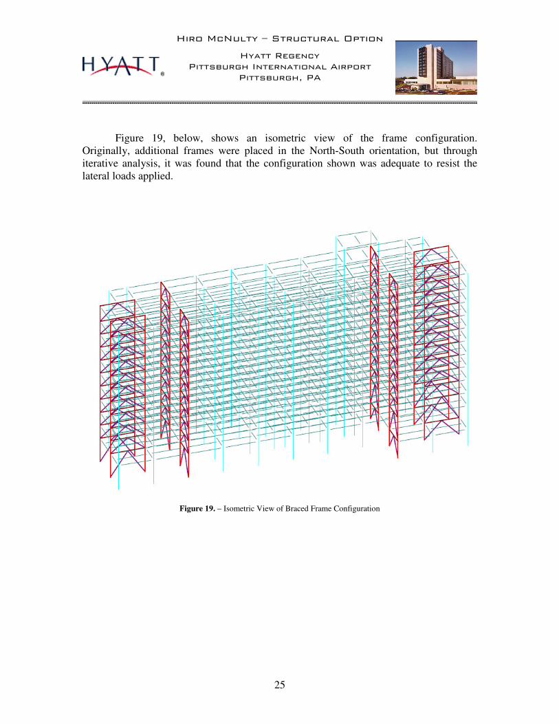
Figure 19, below, shows an isometric view of the frame configuration. Originally, additional frames were placed in the North-South orientation, but through iterative analysis, it was found that the configuration shown was adequate to resist the lateral loads applied.
Figure 19. – Isometric View of Braced Frame Configuration

����������� �� �������� ������
��������������� ����������������������� �������
� �������������
�
26
The frames have been oriented so that they have minimal impact on the floor plan
layout while also being laid out symmetrically to prevent building torsion. The chevron brace members are typically W8X40 in the North-South frames and W12X53 in the East West Frames. Brace slenderness in compression controlled the members in the East-West frames as well as the braces below level 2, which has a larger story height. Below level 2, typical braces are W12X65 in both directions. Figures 20 and 21 below show the member sizes for the frames: beam and column sizes on the left of each figure and brace sizes on the right (separated for clarity).
Figure 20. – North-South Braced Frame Members
Figure 21. – East-West Braced Frame Members

����������� �� �������� ������
��������������� ����������������������� �������
� �������������
�
27
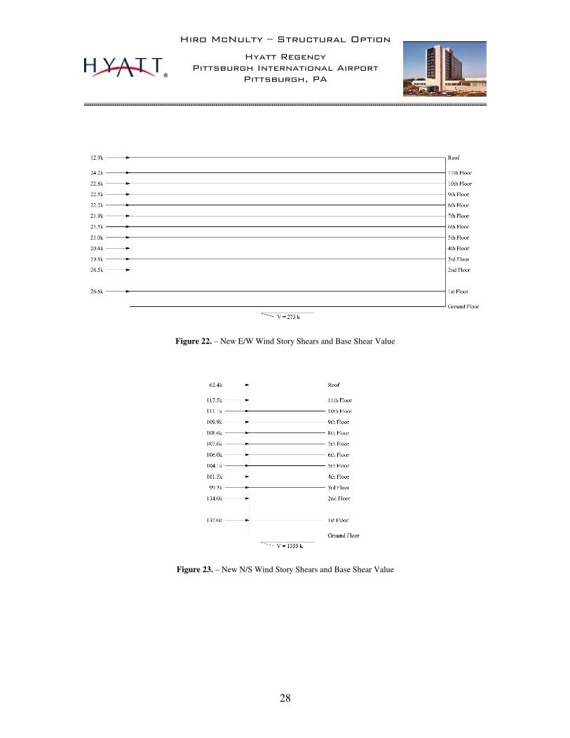
Wind Loads With a change in building height, even a minimal adjustment, the wind loading calculated for the original design needed revision. The height adjustment not only increased the velocity pressure with increased roof elevation, it also increased the area that the wind pressure acted over. Similar to the original calculations, ASCE 7-02 Method 2 – Analytical Procedure was used to determine the lateral loading from wind pressures on the tower. The design factors for the wind loading remains the same, with only the building dimensions changing. From this calculation, the new base shear values are slightly increased from those in the original design. In the North-South direction, the original base shear value was 1321 kips; it is now increased to 1355 kips. In the East-West direction, the original base shear value was 269 kips, increased to 273 kips. While these increases do not significantly impact the design of the lateral force resisting system, it is worth noting that there is a slight increase. Updated story shears have been calculated based on the tributary area of each floor. The new values and new base shears can be seen in Figures 22 and 23. The new loading is slightly conservative as the loading for each story only takes into account a maximum pressure on the tributary area. If the change in pressure with change in height were completely accounted for, the loading would decrease slightly. Below are listed the updated windward and leeward. See Appendix A for calculations.
Windward Wind Pressures:
p0-15 = 10.2 psf ± 2.7 psf p20 = 10.8 psf ± 2.9 psf p25 = 11.3 psf ± 3.0 psf p30 = 11.8 psf ± 3.1 psf p40 = 12.4 psf ± 3.3 psf p50 = 13.1 psf ± 3.5 psf p60 = 13.5 psf ± 3.6 psf p70 = 14.0 psf ± 3.7 psf p80 = 14.5 psf ± 3.8 psf p90 = 14.9 psf ± 3.9 psf p100 = 15.1 psf ± 4.0 psf p120 = 15.7 psf ± 4.2 psf p140 = 16.3 psf ± 4.3 psf p150 = 16.5 psf ± 4.4 psf
Leeward Wind Pressures:
pN/S = -10.3 psf ± 4.4 psf pE/W = -4.1 psf ± 4.4 psf
����������� �� �������� ������
��������������� ����������������������� �������
� �������������
�
28
Figure 22. – New E/W Wind Story Shears and Base Shear Value
Figure 23. – New N/S Wind Story Shears and Base Shear Value

����������� �� �������� ������
��������������� ����������������������� �������
� �������������
�
29
Seismic Loads
New seismic loads were computed using the ASCE 7-02 Equivalent Lateral Force Procedure. Story weights have been calculated based on tributary weight to each floor from RAM model data. The RAM model takeoffs of the gravity beams, gravity columns, and frame members provided the necessary weights to accurately calculate the framing weight. From the new weight and new factors, new story and base shears were calculated and can be seen in Figures 24 and 25. See Appendix B for calculations.
Figure 24. – New E/W Seismic Story Shears and Base Shear Value
Figure 25. – New N/S Seismic Story Shears and Base Shear Value

����������� �� �������� ������
��������������� ����������������������� �������
� �������������
�
30
Impact of New Design on Seismic Loading
Calculation of the seismic loading for the new design changes the applied loads to each floor and base shear values. Based on the new building design, there are a number of design factors that impact the loading.
Building Weight: Based on the building weight and Cs, the seismic response coefficient, the base shear value is calculated. As this calculation is linearly dependent on the weight of the building, the weight has a large effect on the base shear value. For the original structure design, the weight of each floor was calculated to be approximately 1950 kips. For the new structure, typical floor weight was calculated to be around 680 kips (lower floors have slightly larger weight based on increasing column sizes near ground level). This is a decrease of 1270 kips per floor. On an overall building scale, the total building weight calculated for the concrete design was 22,700 kips, whereas the steel framing has a total weight of 7350 kips; this results in a change in total building weight of over 15,000 kips, thus having a large impact on the seismic loading by decreasing the total seismic base shear. Seismic Response Coefficient, Cs: The seismic response coefficient also impacts the seismic base shear. The factor is multiplied by the building weight to determine the total base shear. It is a factor of the design spectral response acceleration, SDS, the importance factor, I, and the response modification factor, R. With the change in framing, the design spectral response acceleration and importance factor do not change, but the response modification factor is changed based on the building frame systems. The original concrete moment frame system has a response modification factor of 3. The new steel braced frames have a response modification factor of 5. In the equation to calculate the seismic response coefficient, the formula is: Cs = SDS/(R/I). As the response modification factor is in the denominator of the equation, the increased value in the new steel braced frames has the effect of decreasing the response coefficient and therefore also decreasing the total base shear value. The response coefficient has been therefore decreased from a value of 0.045 to a value of 0.027, which is still greater than the code minimum of 0.006 (as calculated for this case). Vertical Distribution Factors, Cvx:
To distribute the total base shear vertically into story forces, vertical distribution factors, Cvx, are calculated for each floor. The factor is a function of the floor weight, floor height, and the approximate fundamental period of the structure, Ta. The floor

����������� �� �������� ������
��������������� ����������������������� �������
� �������������
�
31
weight does not have a great impact on the distribution unless a specific level has a much larger weight than other levels. The height of the levels has increased slightly, so the change is factored into the equation. The period of the structure has changed with the change from concrete moment frames to steel braced frames. For the case of concrete moment frames, the fundamental period is allowed to be approximated as 0.1 times the number of stories (not exceeding 12). This provides a period of 1.2 seconds. With the new design, the period is calculated from parameters based on the structure. The new calculated period is 1.26 seconds. This changes the distribution to each story by increasing the exponent, k, on the height of the floor, h. From the distribution, it is found that the loads to the upper levels are significantly larger than those at the lower levels. Table 1, below, shows the distribution of the base shear (198 kips) to each story.
Table 1. - New Seismic Story Force Distribution
Story wx hx wxhxk Cvx Story Force
1 233.2 14 15905 0.002 0.35
2 755.0 34 212967 0.023 4.63
3 702.4 45 310259 0.034 6.74
4 690.6 56 432840 0.047 9.40
5 690.6 67 576695 0.063 12.53
6 683.7 78 728143 0.080 15.82
7 676.7 89 890062 0.098 19.34
8 676.7 100 1072497 0.118 23.30
9 671.9 111 1258408 0.138 27.34
10 667.0 122 1453120 0.159 31.57
11 669.1 133 1673608 0.184 36.36
Roof 168.7 146 489869 0.054 10.64
� 9114374 1.000 198.00

����������� �� �������� ������
��������������� ����������������������� �������
� �������������
�
32
Braced Frame Design
The controlling factor in the design of the members was the slenderness of the member in compression. The tension slenderness ratio of kl/r � 300 was typically met by all initially sized members; however, the kl/r � 200 for members in compression controlled the design and required member sizes to be increased. To meet the slenderness requirements and for constructability, member sizes for braces were selected to be the same through similar frames. This makes the design of the frames in the N-S direction all the same and the frames in the E-W direction are also all the same. Braces are subject to tension and compression forces (axial), so the interaction of moment and axial forces was not significant in these cases.
Frame members have been standardized to keep the stiffness of all frames in one
direction equal. With the concrete slab in place, the floor will act as a rigid diaphragm and distribute loads based on the stiffness of the frame and its distance from the center of rigidity. As the stiffness of the North-South frames are equal and the stiffness of the East-West frames are equal, the spacing of the frames has the only impact on the forces each frame takes. Similarly to the stiffness, all frames in either orthogonal direction are spaced equal distances from the center of rigidity. Therefore, all North-South frames resist an equal portion of the story forces in the North-South direction and all East-West frames resist an equal portion of the story forces in the East-West direction.
The standardization of the bracing members not only simplifies the distribution of
the lateral forces but also helps prevent building torsion. Large torsional forces occur when the applied location of the load has a significant eccentricity to the center of rigidity. With the symmetrical layout of frames, the torsional impact on the building is insignificant.
Drifts were calculated in the RAM model, and compared to an �/400 value for the
building. The calculated value of �/400 for the new building height is 4.8 inches. From the model, calculated drift from the controlling load case of 1.2 D + 0.5 L + 1.6 W was determined to be 4.8 inches in the N/S direction and 0.7 in the E/W direction.
Column and beam sizes were checked to meet the combined force equations H1-
1a and H1-1b, in the Specifications Chapter H in the AISC 3rd Edition LRFD Design Manual. Initial member sizes selected did not meet the combined loading criteria, so were resized to limit all interactions to a value less than 0.95 or 95% of the allowable combined loading. The load case of 1.2 D + 0.5 L + 1.6 W controlled the design of all members in the frames. Most column members remain well below 90% of the allowable combined loading due to the location of the column splices. Members were sized based on the lowest point at a splice, so in levels above (before a new splice), the strength of the member becomes conservative.

����������� �� �������� ������
��������������� ����������������������� �������
� �������������
�
33
Vibration Analysis of New Design
With the large decrease in weight of the new structural design, a vibration analysis was checked to determine if the walking excitations of hotel guests in the corridors would result in unfavorable conditions for guests in the adjacent rooms. Calculations of a typical bay were carried out in accordance to the criterion set in Chapter 4 of AISC Design Guide 11 – Floor Vibrations Due to Human Activity.
In the calculations (see Appendix E), the floor acceleration is calculated and
compared to a recommended limit. For the hotel, the acceleration limit, ao/g, of 0.5% gravity was used, which is the recommended limit value for offices, residences, and churches. From the same general building category, the constant force, Po, was taken to be 65 lb. and the damping ratio, �, was taken as 0.05 (for full height partitions between floors).
The value of the peak acceleration as a fraction of gravity, ap/g was calculated and compared to the acceleration limit. The peak acceleration is a function of the constant force, the damping ratio, the effective weight supported, and the fundamental natural frequency, fn, of the combined panel. The fundamental natural frequency of the beam panel was calculated to be 5.3 Hz. The fundamental natural frequency of the girder panel was calculated to be 9.3 Hz. When the two values are combined into a bay panel frequency, the result was 4.6 Hz. The effective weight supported was calculated to be 41351 lbs. which resulted in a peak acceleration value of 0.006 or 0.6% gravity. From the calculations performed, the floor does not meet the recommended criteria set forth by the design guide. While this may produce unfavorable conditions, it is still possible that guests will not be affected by the vibrations caused by walking in the corridors. Since the building is a hotel, there are typically more partitions than a normal office building or similar structure of this size. As this is the case, it may result that the damping ratio from the increased number of partitions will prevent problems from arising. It can be noted that an increase in the damping ratio from 0.05 to 0.06 (or a 1% increase) results in the peak acceleration calculated to be 0.005 or 0.5% gravity, which is equal to the recommended limit. Remedial measures could also be taken to reduce the effects of the floor vibration. The simplest way of fixing the problem would be to stiffen the beams. As the girder panel frequency is much larger than the beam panel frequency, by increasing the stiffness of the beams, the frequency is increased and this results in a larger combined panel frequency. Typically in a design of this type, larger and stiffer members would be selected in preliminary design, which would increase the frequency of the beam panel and effectively decrease the peak acceleration; however, with the floor-to-floor height

����������� �� �������� ������
��������������� ����������������������� �������
� �������������
�
34
criterion set, the members selected do not allow for the recommended acceleration limit to be met. Overall Impact of the New Design When the foundations are evaluated based on the allowable soil bearing capacity, 2ksf, it is evident that even with the decrease in building size, the deep foundations are the most practical for the situation. Without piles, the required footing size for a typical gravity column would be approximately 19’x19’ and 3 feet deep. While this is not impossible to construct, it results in almost the equivalent of a mat foundation. Mat foundations are difficult to construct, require methods to dissipate heat generated and delay the schedule until the foundation has cured. While the reduced building weight may allow smaller pile configurations, it does not reduce the foundations to a shallow system.
The new steel design has also impacted a number of aspects of the tower that can be discussed and used to evaluate whether or not the new design would be recommended as a good alternative to the original design. The advantages and disadvantages can be compared below. Existing system: Concrete moment frames with 8” filigree slab.
Advantages:
• Filigree slab allows short floor to floor story heights. • Concrete moment frames have little impact on floor layout except at
column locations.
• Filigree slab allows faster construction than typical cast-in-place flat slab or similar concrete construction.
Disadvantages:
• Large building self weight.
• Increased seismic loads due to self weight.
• Longer construction time for cast-in-place sections.
• Large column sizes have some impact on floor plan.

����������� �� �������� ������
��������������� ����������������������� �������
� �������������
�
35
New system: Steel framing with braced frames and 3.5” composite slab.
Advantages:
• Lightweight framing decreases loads to columns and foundations. • Decrease in building seismic loads. • Smaller column sizes.
Disadvantages:
• Slightly increased floor to floor story heights.
• Slightly increased wind loading due to height increase.
• Braced frames restrict openings through frame location.
• Possible vibration issues based on lightweight framing.
• Requires additional fireproofing.
Conclusions of Depth Work
The analysis of the building has proven to show that the seismic loads can greatly be reduced in lightweight structures; in this case the conversion from concrete framing to steel framing. There other issues that are impacted by the new design must be accounted for when determining what the best choice is for the given project. With the redesign to steel framing, the architectural constraints that were set as design criterion were adhered to as closely as possible. The use of the chevron bracing allowed for the openings in the wall to remain where the architects had laid them out in the original design. The new design has greatly decreased the total weight of the structure. As noted, the original structure weight was calculated to be 22,700 kips, whereas the new structural design has a self-weight of only 7,350 kips. This has reduced the seismic base shear to be reduced from 1021 kips to 198 kips. This changes the East-West controlling load case from seismic to wind. The controlling wind load causes a base shear of 269 kips, much less than the previous controlling seismic load.

����������� �� �������� ������
��������������� ����������������������� �������
� �������������
�
36
While the increase in building height does have some impact on the architectural constraints of the building, the building height has increased less than 10%. The FAA regulations on building height in proximity to airports would still need to be enforced; however, it would be possible to reduce the main story height or the overall elevation of the building by adjusting the ground floor level if necessary. In cases where the building was not located adjacent to an airport, the height limitation would widely increase the viability of steel framing over concrete framing. The analysis of walking induced vibrations has also shown that lightweight framing can also have disadvantages for serviceability. While there might not be any complaints based on these vibrations, it is known from the analysis that this case is more susceptible to vibrations than other systems with beams with higher stiffness. From the combination of these analyses, I believe that the original floor system would be the most viable option for the building. Although the steel framing could be adapted for use in this situation, the architectural requirements (including the height limit) in this case would enforce the fact that the low floor-to-floor heights are preferable in this case. The new design has supported the proposal that the seismic loading could be reduced so that wind forces would control in both directions. It has also shown that structural steel framing is an alternative option and will greatly decrease the overall weight of the structure without greatly increasing the floor-to-floor height or overall height of the structure. In this particular building case, the disadvantages of the new system seem to outweigh the advantages that it provides.