overview of jigging process - florida industrial and phosphate
TRANSCRIPT

Publication No. 02-181-242
REMOVAL OF DOLOMITE FROM PHOSPHATE PEBBLE CONCENTRATE BY
ENHANCED JIGGING
FINAL REPORT
Prepared by
Michigan Technological University Houghton, MI
under a grant sponsored by
March 2012


REMOVAL OF DOLOMITE FROM PHOSPHATE PEBBLE CONCENTRATE BY ENHANCED JIGGING
FINAL REPORT
S. K. Kawatra Principal Investigator
with
T. C. Eisele and J. T. Carlson
Department of Chemical Engineering MICHIGAN TECHNOLOGICAL UNIVERSITY
Houghton, MI 49931
Prepared for
UNIVERSITY OF SOUTH FLORIDA POLYTECHNIC FLORIDA INDUSTRIAL AND PHOSPHATE RESEARCH INSTITUTE
1855 West Main Street Bartow, Florida 33830 USA
Contract Manager: Patrick Zhang FIPR Project Number: 09-02-181
March 2012
DISCLAIMER
The contents of this report are reproduced herein as received from the contractor. The report may have been edited as to format in conformance with the FIPR Institute Style Manual. The opinions, findings and conclusions expressed herein are not necessarily those of the Florida Industrial and Phosphate Research Institute or its predecessor, the Florida Institute of Phosphate Research, nor does mention of company names or products constitute endorsement by the Florida Industrial and Phosphate Research Institute. © 2012, Florida Industrial and Phosphate Research Institute.
iii
PERSPECTIVE
Patrick Zhang, Ph.D. – Research Director, Mining and Beneficiation The central Florida phosphate deposits in the Southern Extension may be divided into two zones: an upper zone and a lower zone. The upper zone is readily amenable to the current processing technology, but the lower zone is highly contaminated by dolomite and requires a new method. Dolomite is generally concentrated in the pebble fraction, typically within the size range of 1 to 20 mm. Geological and mineralogical statistics show that up to 50% of the phosphate resource would be wasted if the lower zone is bypassed in mining, and that about 13% of the phosphate resource would be wasted if the lower zone is mined but the dolomitic pebbles are discarded.
Most research on the separation of dolomite from phosphate has focused on the flotation process. Perhaps the most promising process for Florida dolomitic phosphate pebbles is the CLDRI process developed under FIPR funding. In that process, dolomitic pebbles are ground to suitable particle sizes (normally to -100 mesh) for liberating dolomite. The ground slurry is subject to dolomite flotation followed by either silica or phosphate flotation. Pilot-scale testing demonstrated both the technical and economical feasibility of the CLDRI process. However, fine grinding has been one of the major hurdles to commercializing the process due to high energy cost. Because dolomite has a lower specific gravity than phosphate, some gravity separation methods have been tested for separating the two minerals. As a matter of fact, the heavy media separation technology was installed in two Florida plants, and run for several years at one plant. However, heavy media separation is no longer in use due to high cost and low phosphate recovery. Under a previous project, Michigan Tech conducted research for separating dolomite from pebble phosphate using a jig. The method of separation initially centered on the fact that the high-dolomite particles would generate CO2 when exposed to a slightly acidic solution. This generation of CO2 will reduce the apparent density of dolomite particles, rendering better separation using gravity separation equipment, in this case a jig. However, success was achieved without using the complicated and expensive CO2 generation system. The current project focused on improving jigging efficiency using techniques based on gravity separation principles.
Jigging is particularly attractive for this application because of the following: (1) jigs can operate with coarse feeds, thus eliminating costly grinding; (2) operating costs are much lower than flotation or heavy media separation; (3) jigs can be highly selective.
The best performance on a crushed feed of about 2% MgO achieved a concentrate containing 0.84% MgO with a BPL recovery of 55.4%. For an uncrushed sample of 3.20% MgO, the phosphate concentrate averaged 1.5% MgO at a BPL recovery of 80.5%. These results are quite promising, considering that jigging is about 20 times less expensive than heavy media separation and 6 times less than flotation, as estimated in this report.

v
ABSTRACT
Dolomite [CaMg(CO3)2] is an objectionable impurity in phosphate ores due to its MgO content. Separating dolomite from phosphate ores (apatite) has proven to be difficult due to very similar mineralogical properties. It is desired that a process reduce MgO content in the concentrate to less than 1%, while still achieving respectable phosphate recoveries.
Jigging was investigated as a low-cost physical separation method for the removal
of dolomite from high-MgO phosphate ores. It was determined by liberation analysis that the dolomite is sufficiently liberated from phosphate, making it theoretically possible to remove a significant amount of MgO without crushing or grinding. A laboratory-scale jig was designed and built to examine the feasibility of jigging as a process for separating dolomite from phosphate pebble. Using a batch jigging procedure, it was determined that the optimal pulsation frequency was 200 pulsations/minute.
A continuous jigging laboratory-scale testing procedure was developed and
alumina balls were used as ragging material. Jigging tests were completed using different phosphate ores with water as the jigging fluid. Use of a dense jigging fluid (CaCl2 solution) was explored as a possible method for increasing separation efficiency. It was found that using a dense fluid resulted in an increase in dense particle recovery rate, corresponding to approximately a 52.3% increase in throughput over experiments run with water.
Contact angle experiments were conducted to determine whether existing froth
flotation reagents could make dolomite sufficiently hydrophobic for a novel “flotation jigging” process. It was found that the available reagents could not provide sufficient hydrophobicity to reliably separate dolomite from phosphate. These experiments also indicated that conventional froth flotation would not be expected to provide adequate dolomite removal using these reagents.
Cost estimation calculations are included that indicate that a jig process is
approximately 1/20th the cost of a comparable-capacity heavy-media process for removing dolomite. It was also calculated that a jig process would be cheaper than a froth flotation process, even if a suitable dolomite flotation reagent becomes available that is useful for conventional flotation.

vi
ACKNOWLEDGMENTS The financial support of the Florida Institute of Phosphate Research (FIPR) is gratefully acknowledged. The authors would also like to acknowledge The Mosaic Company and CF Industries for supplying the phosphate ore samples used to conduct this research project.

vii
TABLE OF CONTENTS PERSPECTIVE.................................................................................................................. iii ABSTRACT ....................................................................................................................... iii ACKNOWLEDGMENTS ................................................................................................. vi EXECUTIVE SUMMARY ................................................................................................ 1 INTRODUCTION .............................................................................................................. 5
Background ............................................................................................................. 5 Jigging Theory ........................................................................................................ 6
Overview of Jigging Process ...................................................................... 6 Jigging with a Dense Fluid ......................................................................... 7 Flotation/Jigging ......................................................................................... 7 Variables Involved in the Jigging Process .................................................. 8
MATERIALS AND METHODS ........................................................................................ 9
Characterization of High-MgO Phosphate Ore ....................................................... 9
Screening, Splitting, and Preparation of Samples ....................................... 9 X-Ray Diffraction ..................................................................................... 10 MgO Analysis ........................................................................................... 10 BPL Analysis ............................................................................................ 14 Carbonate Analysis ................................................................................... 16 Liberation Analysis ................................................................................... 19 Removal of MgO by Sizing ...................................................................... 20
Confirmation of Analytical Methods .................................................................... 21 Characterization of CaCl2 Solution ....................................................................... 23
DowflakeXTRA Solution Density Measurements.................................... 23 DowflakeXTRA Solution Viscosity Measurements ................................. 24
EXPERIMENTAL SETUP AND DESIGN FOR JIGGING STUDIES .......................... 27
Jig Design and Operation ...................................................................................... 27
Design of Laboratory-Scale Jig ................................................................ 27 Design of Smaller-Scale Laboratory Jig ................................................... 28 Batch Jigging Procedure ........................................................................... 29

viii
TABLE OF CONTENTS (CONT.)
Continuous Jigging Procedure .................................................................. 30
Optimization of Jigging Parameters...................................................................... 31
Optimization of Pulsation Rate ................................................................. 31 Optimization of Stroke Length and Hutch Water Flow Rate ................... 32 Effects of Ragging Density ....................................................................... 32
Jigging with Different Phosphate Feeds ............................................................... 33
Crushed Higher-MgO Feed ....................................................................... 33 Uncrushed Higher-MgO Feed ................................................................... 34
Jigging with a Dense Fluid ................................................................................... 35
Batch-Scale Dense Fluid Jigging Experiments ......................................... 35 Dense Fluid Continuous Jigging Experiments with Crushed Feed .......... 35 Jigging with a Dense Fluid—Factorial Experiments ................................ 36
RESULTS AND DISCUSSION OF JIGGING EXPERIMENTS ................................... 37
Jig Optimization Results ....................................................................................... 37
Optimization of Pulsation Rate in Batch Experiments ............................. 37 Optimization of Stroke Length and Hutch Water Flow Rate ................... 38 Effect of Ragging Density in Continuous Jigging .................................... 39
Jigging with Different Phosphate Feeds ............................................................... 40
Crushed Higher-MgO Feed ....................................................................... 40 Uncrushed Higher-MgO Feed ................................................................... 41
Jigging with a Dense Fluid ................................................................................... 44
Preliminary Batch-Scale Dense Fluid Jigging Experiments ..................... 44 Preliminary Dense Fluid Jigging Experiments ......................................... 45 Jigging with a Dense Fluid ....................................................................... 46
CONTACT ANGLE AND FLOTATION EXPERIMENTS ........................................... 51
Contact Angle Experiments .................................................................................. 51
Contact Angle Experimental Procedures .................................................. 51

ix
TABLE OF CONTENTS (CONT.)
Sample Preparation ........................................................................51 Reagent Solution Preparation ........................................................52 Sample Conditioning .....................................................................52 Contact Angle Measurements ........................................................53
Results and Discussion for Contact Angle Experiments .......................... 54 Conclusions from Contact Angle Experiments......................................... 55
Flotation Experiments ........................................................................................... 56
Flotation Experiment Procedures .............................................................. 56
COST ESTIMATION ANALYSIS .................................................................................. 59
Cost Estimation Procedures and Calculations ...................................................... 59
General Cost Estimation Procedure .......................................................... 59 Cost Estimation of Jigging Process .......................................................... 60
Cost Estimation of Jig ....................................................................61 Cost Estimation of Extras for Jigging Process ...............................62 Total Estimated Cost of Jigging Process .......................................63
Cost Estimation for Heavy Media Separation Process ............................. 63 Cost Estimation for Flotation Process....................................................... 65
Cost Estimation for Flotation Cells................................................65 Cost Estimation of Extras for the Flotation Process ......................67 Total Estimated Cost of Flotation ..................................................68
Cost Estimate Summary ........................................................................................ 68
CONCLUSIONS............................................................................................................... 69 REFERENCES ................................................................................................................. 71

xi
LIST OF FIGURES Figure Page 1. Mechanisms of Particle Stratification During the Jigging Process (figure
adapted from Gupta and Yan 2006) ......................................................................6 2. Diagram of Jigging Flotation Process. ................................................................. 8 3. Description of Variables Involved in the Jigging Process (Karantzavelos
and Frangiscos 1984) ........................................................................................... 8 4. Method for Sizing, Splitting, and Preparing Sample from High-MgO
Phosphate Pebble ................................................................................................. 9 5. X-ray Diffraction Analysis of High-MgO Phosphate Pebble ............................ 10 6. Varian AA240FS Fast Sequential Spectrometer Used for MgO Analysis ........ 11 7. Percent of Total Weight in Each Size Fraction for the High-MgO
Phosphate Pebble ............................................................................................... 13 8. MgO Analysis of High-MgO Phosphate Pebble. ............................................... 13 9. Hach DR 5000 UV-Vis Spectrophotometer Used for BPL Analysis ................ 14 10. BPL Analysis of High-MgO Phosphate Pebble. ................................................ 16 11. Diagram Showing TGA of High-Dolomite Phosphate Ore (+2.5M Size
Fraction). ............................................................................................................ 17 12. Leco TGA701 Thermogravimetric Analyzer Used for Carbonate Analysis ..... 18 13. TGA Results for All Size Fractions of High-MgO Phosphate Ore ................... 18 14. Carbonate (CO3) Analysis of High-MgO Phosphate Ore. ................................. 19 15. Histogram Results of Liberation Analysis for High-MgO Phosphate Ore ........ 20 16. MgO Rejection Versus BPL Recovery for a Screening Process ....................... 21 17. Comparison of MgO Analyses Done at MTU with Results from a
Phosphate Industry Lab...................................................................................... 22 18. Comparison of BPL Analyses Done at MTU with Results from a
Phosphate Industry Lab...................................................................................... 22 19. Solution Density Measurements at Various DowflakeXTRA
Concentrations ................................................................................................... 23 20. Solution Kinematic Viscosity Measurements at Various DowflakeXTRA
Concentrations ................................................................................................... 24 21. Kinematic Viscosity and Density Measurements for each recycle of CaCl2
Solution. ............................................................................................................. 25 22. Photo of Large Laboratory-Scale Jig ................................................................. 27 23. Laboratory Jig Complete Experimental Setup. .................................................. 28 24. Smaller U-Shaped Laboratory-Scale Jig. ........................................................... 29 25. Jig Top Broken Down into Four Zones ............................................................. 29 26. Comparison of "Over the Screen" and "Through the Screen" Jigging
Processes. ........................................................................................................... 31 27. Diagram Describing the Function of Ragging in the Jigging Process ............... 31 28. Results from Pulsation Rate Optimization Experiments Plotted as MgO
Rejection Curves. ............................................................................................... 37 29. Effects of Stroke Length and Hutch Water Flow Rate on Jigging Process ....... 39

xi
LIST OF FIGURES (CONT.) Figure Page 30. Grade Versus Recovery Curve for Ragging Density Experiments. ................... 40 31. Grade Versus Recovery Curve for Experiments Using a Crushed
Higher-MgO Feed. ............................................................................................. 41 32. Grade Versus Recovery Curve for Uncrushed Higher-MgO Phosphate Ore .... 43 33. Hand-Separated CF Industries 6×20 Mesh Sample ........................................... 43 34. Total % MgO Removed Versus Weight % Rejected for Preliminary
Batch-Scale Jigging Experiments with a Dense Fluid. ...................................... 44 35. Grade Versus Recovery Curve for Preliminary Dense Fluid Jigging
Experiments ....................................................................................................... 45 36. Sample of High-MgO Mosaic Phosphate Ore (5×20 Mesh) Hand-Separated
into Four Different Categories: Dark Black Pebbles, Light Gray Pebbles, Light Yellow Pebbles, and Silica Pebbles ......................................................... 47
37. Grade Versus Recovery Curve for Dense Fluid Jigging Studies. ...................... 47 38. Feed Rate Versus Recovery Curve for Dense Fluid Jigging Studies................. 48 39. Grade Versus Recovery Curve for Dense Fluid Jigging Studies, with Trend
Lines Included. ................................................................................................... 48 40. Feed Rate Versus Recovery Curve for Dense Fluid Jigging Study
Including Average Recoveries at Each Condition ............................................. 49 41. Dolomite (left) and Apatite (right) Pebbles After Being Ground into
"Slices". .............................................................................................................. 52 42. Photo of Tantac CAM-PLUS Contact Angle Meter. ......................................... 53 43. Example Photo showing Contact Angle Measurement Using the Half-Angle
Method. .............................................................................................................. 53 44. Procedures Used for Dolomite Flotation Experiments. ..................................... 57 45. Cost Estimation for Jigs (Without Extras) (Mular 1982). .................................. 62 46. Cost Estimation for Heavy Media Separation (Mular 1982). ............................ 65 47. Cost Estimation of Flotation Cells (Without Extras) (Mular 1982). ................. 67

xiii
LIST OF TABLES Table Page 1. Chemical Composition of DowflakeXTRA as Supplied by Manufacturer ....... 23 2. Experimental Design for Optimization of Stroke Length and Hutch Water
Flow Rate ........................................................................................................... 32 3. Experimental Design for Ragging Density Experiments. .................................. 33 4. Jigging Parameters Used in Ragging Density Experiments .............................. 33 5. Jigging Parameters for Higher-MgO Experiments ............................................ 33 6. Characterization of CF Industries Phosphate Ore. ............................................. 34 7. Jigging Parameters Used for Uncrushed High-MgO Phosphate Ore
Experiments ....................................................................................................... 34 8. Jigging Parameters for Preliminary Batch-Scale Dense Fluid Jigging
Experiments ....................................................................................................... 35 9. Jigging Parameters Used in Preliminary Dense Fluid Jigging Experiments ..... 35 10. Experimental Design for Dense Fluid Jigging Studies. ..................................... 36 11. Jigging Parameters for Dense Fluid Jigging Studies ......................................... 36 12. Pulsation Rate Optimization Results Corresponding to Figure 28 .................... 38 13. Results for Uncrushed Higher-MgO Phosphate Feed Experiments .................. 42 14. Results from Preliminary Batch-Scale Jigging Trials with a Dense Fluid ........ 44 15. Results from Dense Fluid Jigging Studies. ........................................................ 46 16. Contact Angle Measurements at a Reagent Dosage of 0.5 kg/ton at a pH
of 4.5 .................................................................................................................. 54 17. Contact Angle Measurements at a Reagent Dosage of 2 kg/ton at pH of 4.5.... 54 18. Contact Angle Measurements at a Reagent Dosage of 0.5 kg/ton at pH
of 4.5 .................................................................................................................. 55 19. Results from Dolomite Flotation Experiments .................................................. 57 20. Particle Size Analysis of Concentrate and Tailings from Flotation
Experiments ....................................................................................................... 58 21. Jig Cost Estimation Parameters (Mular 1982) ................................................... 61 22. Jig Cost Estimation Specifications (Mular 1982) .............................................. 62 23. Cost Estimation Parameters and Specifications for Heavy Media Separation
Process (Mular 1982). ........................................................................................ 64 24. Flotation Cell Cost Estimation Parameters and Specifications (Mular 1982). .. 66

1
EXECUTIVE SUMMARY Phosphate rock is a fundamental mineral needed in the production of phosphorus based fertilizers. With world population continuing to rise, the demand for phosphate rock will continues to increase. As high-grade phosphate reserves become depleted, the phosphate industries will be force to begin mining lower-grade high-dolomite phosphate reserves. If not removed from the phosphate concentrate, dolomite is problematic to the wet process production of phosphoric acid in two ways: (1) dolomite reacts with the sulfuric acid, which leads to higher sulfuric acid consumption, and (2) dolomite impurities increase the viscosity of fluid, which increases filtration costs in the gypsum removal step. Developing an efficient and cost effective method for removing dolomite from sedimentary phosphate rock has proven to be difficult due to the dolomite and the phosphate-bearing minerals having very similar chemical and physical properties. Many conventional methods such as flotation, strong and weak acid leaching, calcination, and physical separation methods have been attempted and reported in the literature, but have not been commercially successful. Many of these methods are hindered by high operating costs and low separation efficiencies. This project investigated jigging as a method for removing dolomite. Jigging is particularly attractive for this application because of the following:
(1) Jigs can operate with coarse feeds, and so can process feeds that have not been crushed or ground. Since the dolomite in Florida phosphates is normally present as discrete pebbles rather than as inclusions locked to the phosphate minerals, it is not necessary to reduce the size of the particles to liberate the dolomite.
(2) Operating costs are relatively inexpensive when compared to other
conventional mineral processing methods. This is due to the mechanical simplicity of jigs, and to the fact that they do not require expensive consumables or chemical reagents.
(3) Jigs can be highly selective when operated correctly. They also separate
particles based on density differences rather than on absolute density, and so they can continue to work efficiently even when the absolute densities of the particles being processed are somewhat variable. The goal of this project was to evaluate jigging as a method for the beneficiation of high-MgO sedimentary phosphate ores, and it consisted of the following objectives:
(1) Characterization of phosphate samples supplied by Florida phosphate companies
(2) Design and construction of specialty laboratory-scale jigs for separation
experiments

2
(3) Optimization of laboratory-scale jig using continuous testing procedures (4) Investigation of enhanced jigging using a dense jigging fluid (5) Contact angle measurements and flotation experiments for the feasibility of a
flotation/jigging process, and (6) Estimate the costs associated with a jigging process compared with those of
competing processes. High-MgO phosphate samples were received from The Mosaic Company and CF Industries. Each sample was systematically split to achieve representative samples for jig testing, along with representative samples for characterization of the two ores. X-ray diffraction showed that the phosphate ore consisted mostly of apatite, dolomite, and silica. During characterization it was determined that the coarse pebble size fraction (+3 mesh) contained a disproportionate fraction of the MgO. Screening at this size could reject nearly 40% of the MgO in the coarse fraction, while still recovering approximately 85% of the phosphorus in the fine fraction. A liberation analysis was also performed by analyzing individual pebbles for MgO content. It was determined that the dolomite was significantly liberated from the phosphate minerals even at the coarser pebble sizes. This showed that crushing and grinding was not needed to liberate the dolomite before jig processing. To conduct laboratory-scale jigging experiments, a special 4-inch (10 cm) diameter laboratory-scale jig was constructed to allow for the modification and optimization of the most important jigging parameters. The jigging parameters that were investigated were pulsation rate, stroke length, hutch water flow rate, and feed rate (for continuous testing procedure). Using a batch-scale testing procedure, pulsation rates of 100, 200, and 300 pulsations/minute were tested. Results indicated that a pulsation frequency of 200 pulsations/minute gave in the best separation. To further optimize the jigging process for the removal of dolomite from phosphate ores, a continuous jigging testing procedure was developed. This included the addition of alumina ragging balls and a vibratory feeder. Experiments were conducted to optimize stroke length and hutch water flow rate. It was determined that for this specific jigging device and phosphate feed, a stroke length of 1 inch and hutch water flow rate of 0.5gpm are optimal. It was also determined that stoke length had a significantly greater effect on separation efficiency than the hutch water flow rate. With the dolomite pebbles provided for testing by Mosaic, it was found that MgO levels could be reduced to below 1% while still recovering approximately 50% of the pebble weight. This shows that the jig process is capable of making the desired specification. Based on jigging theory, two possible avenues for enhancing jigging efficiency were investigated: (1) increase the density of the jigging fluid; and (2) add a flotation aspect to the jigging process to increase the apparent density difference between dolomite and apatite.

3
Increasing the density of the jigging fluid increases the value of the
Concentration Criterion = h f
l f
D DD D
− −
, where Dh is the density of the heavier mineral, Dl
is the density of the lighter mineral, and Df is the density of the fluid. Since higher values of the concentration criterion indicate more effective separation by the jig, the use of denser fluid will tend to improve jig performance, although increased fluid viscosities will hinder particle movement and decrease separation. For this study, calcium chloride was used to create a dense jigging fluid. By measuring the densities and kinematic viscosities of several CaCl2 solutions, it was determined that a solution concentration of 20-25wt% produced a significantly denser jigging fluid with only a small increase in fluid viscosity. Experiments were conduction with a CaCl2 solution of 22wt%, which had a measured density of approximately 1.20g/cm3. A 2×2 factorial design was constructed using feed rate (high≈160 g/min. and low≈55 g/min.) and jigging fluid density (tap water≈1 g/cm3 and CaCl2≈1.20 g/cm3) as the variables. When using the same feed, it was observed that the dense jigging fluid resulted in a higher recovery (or throughput) for this process. From the results, it was estimated that the dense jigging fluid increased the throughput by approximately 52.3%. It is believed that the increase in throughput could be a result of greater fluidization of the ragging material by the denser and more viscous CaCl2 solution. Adding a flotation aspect to the jigging process was also investigated as a method for increasing jigging efficiency. If an appropriate reagent could be used to selectively induce hydrophobicity on the dolomite pebbles so that air bubbles would attach to the surfaces, the apparent density difference between the dolomite and phosphate pebbles would be increased, raising the value of the concentration criterion. As a result, jigging efficiency would be improved. The key to implementing a jigging/flotation process therefore lies with finding a selective dolomite flotation reagent. Several reagents were received and tested for effectiveness by way of contact angle measurement for both dolomite and apatite pebbles, at varying conditioning parameters. It was found that the available reagents could not provide sufficient hydrophobicity to reliably separate dolomite from phosphate. Finally, costs estimations for the jigging process, froth flotation, and heavy media separation were conducted. Using 100 tons per hour feed basis, the cost a fully-equipped jig was estimated at $50,135. For comparison, a heavy media separation process of similar throughput had an estimated cost of $1,031,289, which is approximately 20 times greater than the cost of the jig plant. In addition, 100 ton per hour capacity froth flotation plant was estimated at $322,360, which is approximately 6.4 times more than the jig plant. Therefore, the jigging process is dramatically cheaper than both heavy media separation and froth flotation. Overall, the jigging process was shown to be capable of separating dolomite from phosphate-bearing minerals, and experiments with hand-sorting of particles showed that the jig approaches the minimum achievable levels of MgO for a given phosphate rock sample. When the individual phosphate pebbles have a low level of contained MgO, then the jig can produce a similarly low-MgO product by removing the discrete MgO-bearing

4
pebbles. The significantly lower cost of the jigging process compared to other processing methods makes it a viable approach to removing dolomite from Florida phosphate deposits.

5
INTRODUCTION BACKGROUND
Phosphate rock is a fundamental mineral used to produce fertilizers. Traditionally, the Florida phosphate industry has been able to mine high-grade reserves, such as those of the Bone Valley of Florida. However, as high-grade reserves become depleted, the phosphate industry will be forced to move operations into lower-grade reserves (Gu and others 1999). These lower-grade reserves typically contain dolomite [CaMg(CO3)2], which has negative effects on the wet production of phosphoric acid. If not removed, dolomite (1) increases sulfuric acid consumption, and (2) decreases filtration rates by increasing fluid viscosity. In general, the phosphate industry demands a phosphate concentrate containing less than 1% MgO.
Separating dolomite from apatite has proven to be very difficult due to very similar mineralogical properties (Somasundaran and Zhang 1999). Many methods have been attempted including flotation (reverse and direct), acid leaching (strong and weak), calcination, and physical separation (El-Shall and others 1996). Although some of these methods have been shown to produce encouraging results, there is still no widely accepted economical process for removing dolomite from phosphate ores. One method that has not yet been tried for the removal of dolomite from phosphate ores is jigging.
The objective of this project has been to develop a low-cost physical separation technique for removing dolomite from phosphate rock. The primary approach taken has been jigging, with jigs designed and optimized specifically to be effective when density differences between the minerals are small. The project consisted of the following activities: (1) characterization of phosphate pebble to determine liberation of dolomite from phosphate, (2) design and construction of specialty lab-scale jigs for separation experiments, (3) optimization of laboratory-scale jig using a continuous testing procedure, (4) investigation of enhanced jigging using a dense jigging fluid, and (5) contact angle measurements and flotation experiments for the feasibility of a flotation/jigging process.
Jigs are particularly promising because they are high-capacity and are considerably less expensive than the previously attempted heavy media separation processes. Based on a 100 tph unit, a heavy media vessel ($1,031k; 2011 dollars) is estimated to cost approximately 20 times more than a jig unit ($50k; 2011 dollars) (Mular 1982; Reeves 2002). Heavy media separation is particularly expensive due to the need for extra support equipment such as magnetic separators, reclaim screens, pumps, and sumps. Jigging has a lower operating cost because minimal support equipment is needed.

6
JIGGING THEORY Overview of Jigging Process
Jigging is a gravity concentration method that separates minerals of different densities by a continuous expansion and compaction of a particle bed. Figure 1 shows the ideal jigging process including the separation mechanism involved. First, the particle bed is fluidized by the pulsation stroke, where initial differential separation is the main separating mechanism. Initial differential acceleration separates particles purely by density. Second, as the particles begin to reach terminal velocity, drag forces begin to play a role and hindered settling becomes the mechanism of separation. Hindered settling separates particles based on size and density. Finally, during the suction stroke, fine particles penetrate through coarse particles and into the dense particle concentrate. This is referred to as consolidated trickling. Some major advantages of the jigging process include the following:
(1) Jigs can operate with coarse particle feeds (2) Jigging is relatively inexpensive compared to heavy media separation and
flotation, and (3) Jigs can be selective when operated correctly.
Figure 1. Mechanisms of Particle Stratification During the Jigging Process (figure
adapted from Gupta and Yan 2006).

7
Since jigging is a gravity separation method, the efficiency of the process is highly dependent on the density difference between the minerals being separated. As a rule of thumb, the concentration criterion (Equation 1) is used to determine the feasibility of a gravity concentration process (Gupta and Yan 2006)
Concentration Criterion = h f
l f
D DD D
− −
(1)
where Dh is the density of heavy mineral, Dl is the density of light mineral, and Df is the density of the fluid. In general, a concentration criterion less than 1.25 means that the separation is not economically possible with currently available gravity concentration methods. Jigging with a Dense Fluid
When looking at Equation 1, it is apparent that a possible method for increasing the concentration criterion would be by increasing the density of the jigging fluid. Possible dense fluids could include a dissolved salt solution (CaCl2) or magnetite suspension. It should be noted that increasing the viscosity of the jigging fluid has been shown to retard particle movement and hinder particle separation, making it important to increase the density of the solution without significantly increasing the viscosity (Gupta and Yan 2006). Flotation/Jigging
Another possible method for increasing the concentration criterion would be by decreasing the apparent density of the dolomite pebbles. This could be accomplished by combining a flotation process with the jigging process. Figure 2 shows a diagram of how the proposed combination jigging/flotation method would in theory work. Air bubbles would be added through the hutch of the jig by way of air sparging system or venturi aspirator. The air bubbles would then selectively adhere to the dolomite particles, making them appear less dense, and increasing the concentration criterion. However, in order for a process such as the jigging/flotation method to work, there must be an adequate reagent available for the selective flotation of dolomite from apatite. As mentioned before, finding a selective reagent for the flotation of dolomite from apatite has been problematic due to very similar mineralogical properties.

8
Phosphate
Air bubbles adhering to hydrophobic dolomite
Injected Air
Pulsation
Figure 2. Diagram of Jigging Flotation Process. Variables Involved in the Jigging Process Jigging is a relatively complex process due to many interrelating variables and parameters. Figure 3 lists the independent and dependent variables involved in the jigging process. The independent variables are further broken down into disturbance variables and manipulated variables. Disturbance variables are mainly properties of the feed ore, making them mostly unchangeable. On the other hand, the manipulated variables are essentially jigging parameters that can be optimized for a particular separation. Overall, the manipulated variables must be optimized and modified to account for disturbances in feed properties. Dependent variables are primarily metrics that can be used to quantify the efficiency of the jigging process.
Figure 3. Description of Variables Involved in the Jigging Process (Karantzavelos
and Frangiscos 1984).

9
MATERIALS AND METHODS CHARACTERIZATION OF HIGH-MgO PHOSPHATE ORE
For this study, two 55-gallon drums of high-dolomite phosphate pebble were initially received from Mosaic, a large producer of phosphate rock in Florida. The first step after receiving the high-MgO phosphate ore sample was to perform a full mineral characterization. The characterization section is broken into the following sections: (1) screening and preparation of samples, (2) X-ray diffraction, (3) MgO analysis, (4) BPL analysis, (5) CO3 analysis, (6) liberation analysis, and (7) removal of MgO by sizing. Screening, Splitting, and Preparation of Samples
Florida phosphate ore is sedimentary in nature, formed in the shape of pebbles ranging in sizes of very large (>8 mm) to superfine. It has been noted in literature that the coarse pebbles contain significantly more dolomite (MgO) than the finer pebbles (El-Shall and others 1996). For this reason, it was important that the phosphate pebble be sized into different size fractions, to measure the natural distribution of MgO content by size. Initially, the first barrel of phosphate ore was sized into 3 different size fractions: +3 mesh (+6.73 mm), 3×6 mesh (-6.73/+3.36 mm), and -6 mesh (-3.36 mm). Figure 4 shows the process used for preparing representative samples of each size fraction.
Riffle Splitter
Riffle Splitter
Screening
12
14
3 mesh
6 mesh
Rotary Splitter
55 gallons
Rotary Splitter Puck Mill
Short-head Crusher
Roll Crusher Samples
+3 mesh sample
-3 by +6 mesh
sample
-6 mesh sample
11/12ths to samples for experiments
1/12th for analytical sample
Figure 4. Method for Sizing, Splitting, and Preparing Sample from High-MgO
Phosphate Pebble.

10
X-Ray Diffraction
X-ray diffraction was used to determine what minerals were present in the high-MgO phosphate ore. The XRD results shown in Figure 5 indicated that the three main minerals present in the ore are dolomite, apatite, and SiO2/quartz. It should be noted that the apatite is of the carbonate-rich variety called francolite, which is usually present in sedimentary phosphate pebble, like that found in the Bone Valley reserves of central Florida (UNIDO and IFDC 1998).
It can also be inferred from the relative peak sizes that the amount of dolomite (MgO) is greatest in the coarse size fraction (+3 mesh). The dolomite peaks decrease in size along with the particle size fractions, indicating that the amount of dolomite present decreases with particle size. Atomic absorption spectrometry was later used to quantify this observation.
Figure 5. X-ray Diffraction Analysis of High-MgO Phosphate Pebble. MgO Analysis
Dolomite is a magnesium-bearing impurity that must be removed from the phosphate ore. The phosphate industry demands a phosphate concentrate containing less than 1% MgO. Therefore, accurate and precise measurements of MgO are crucial in determining the quality of the phosphate ore. Atomic absorption spectrometry was chosen as the method for MgO analysis throughout this project. An acid digestion and

11
dilution process was used to prepare atomic absorption samples. The spectrometer used was a Varian AA 240FS fast sequential atomic absorption spectrometer, which is shown in Figure 6.
Figure 6. Varian AA240FS Fast Sequential Spectrometer Used for MgO Analysis.
The analytical procedure used is as follows: Acid Digestion Procedure
Step (1) Measure 0.5 g of dried and pulverized phosphate sample and put in 100 ml beaker.
Step (2) Add 10 ml of concentrated HCl acid, cover with watch glass, and
heat on hot plate for 3-5 minutes. Step (3) Filter the solution using a 90 mm diameter Buchner funnel with
Whatman 1 filter paper. Record filter paper weight before and after filtration to estimate acid insolubles (silica) content.
Step (4) Wash filter paper 4 times with distilled water (approximately 400
ml total). Transfer to 500 ml volumetric flask and dilute to mark with distilled water. Mix contents by inverting the flask 25 times. This sample is used for both MgO and BPL analyses.
Making Standard Solutions for AA Analysis
Step (1) Add 80 µl of a 1000 ppm magnesium AA standard solution to a 200 ml volumetric flask. Dilute to mark with distilled water and mix by inverting 30 times. This is standard solution #3.

12
Step (2) Transfer 100 g of standard solution #3 to a 200 ml volumetric flask. Dilute to mark with distilled water and mix by inverting 30 times. This is standard solution #2.
Step (3) Transfer 100g of standard solution #2 to a 200 ml volumetric
flask. Dilute to mark with distilled water and mix by inverting 30 times. This is standard solution #1.
Step (4) Fill and empty 200 ml volumetric flask with distilled water. This
is the calibration zero standard. Atomic Absorption Analysis
Step (1) Using a micropipette, add 1ml of the acid digested solution to a 100ml volumetric flask. Dilute to mark with distilled water, and mix by inverting flask 25 times. For samples with higher MgO concentrations, add less (down to 100 µl) of the digested solution.
Step (2) Repeat Step 1 three times (creating 3 diluted samples) for each
sample for reproducibility. Step (3) Set up Varian AA 240FS for MgO analysis and measure MgO
content of diluted solution. Calculate the total amount of MgO in the 0.5 g sample taking into account the dilution factor and determine total percent MgO in the sample.
It was determined by x-ray diffraction that the amount of dolomite (MgO) present
is greatest in the +3 mesh size fraction, with MgO content decreasing as natural size fraction decreases. For this reason, more analytical samples were prepared from the phosphate ore from the following size fractions: +2.5 mesh, 2.5×3 mesh, 3×4 mesh, 4×5 mesh, 5×6 mesh, 6×8 mesh, 8×10 mesh, 10×12 mesh, 12×14 mesh, and -14 mesh. Figure 7 shows the % of total weight for each size fraction and Figure 8 gives the results of the MgO analysis.
The coarsest size fraction (+2.5 mesh) has the highest concentration of MgO at approximately 5.75% MgO. MgO levels decrease steadily from the coarser- to finer-size fractions. One thing that should be noted is the slight increase in MgO content from the 12×14 mesh to the -14 mesh size fraction. This can be attributed to the fact that dolomite is significantly softer than apatite, resulting in the production of high MgO fines (Zhang 1993).

13
0.0%
10.0%
20.0%
30.0%
40.0%
50.0%
60.0%
70.0%
80.0%
90.0%
100.0%
%W
eigh
t
Size Fraction (Tyler Mesh)
Size Analysis
Figure 7. Percent of Total Weight in Each Size Fraction for the High-MgO
Phosphate Pebble.
0.00%
1.00%
2.00%
3.00%
4.00%
5.00%
6.00%
7.00%
% M
gO
Size Fraction (Tyler Mesh)
%MgO Analysis
Figure 8. MgO Analysis of High-MgO Phosphate Pebble.

14
BPL Analysis Bone phosphate of lime (BPL) is used to quantify the quality of the phosphate concentrate. BPL, or tricalcium phosphate (Ca3(PO4)2), was determined using UV-Vis spectroscopy. For this photometric method, phosphate samples were first dissolved in acid and then reacted with a reagent solution to produce a yellow-colored complex. Standards were created using monopotassium phosphate, and measurements were converted to BPL by a simple conversion (P2O5 × 2.1853 = BPL) (Notholt and others 1989). The spectrophotometer used was a Hach DR 5000 UV-Vis spectrophotometer, which is shown in Figure 9.
Figure 9. Hach DR 5000 UV-Vis Spectrophotometer Used for BPL Analysis. Detailed analytical procedures are given below (Barton 1948, Quinlan and DeSesa 1955). Acid Digestion Procedure
Step (1) Measure 0.5 g of dried and pulverized phosphate sample and put in 100 ml beaker.
Step (2) Add 10 ml of concentrated HCl acid, cover with watch glass, and
heat on hot plate for 3-5 minutes. Step (3) Filter the solution using a 90 mm diameter Buchner funnel with
Whatman 1 filter paper. Record filter paper weight before and after filtration to estimate acid insolubles (silica) content.
15
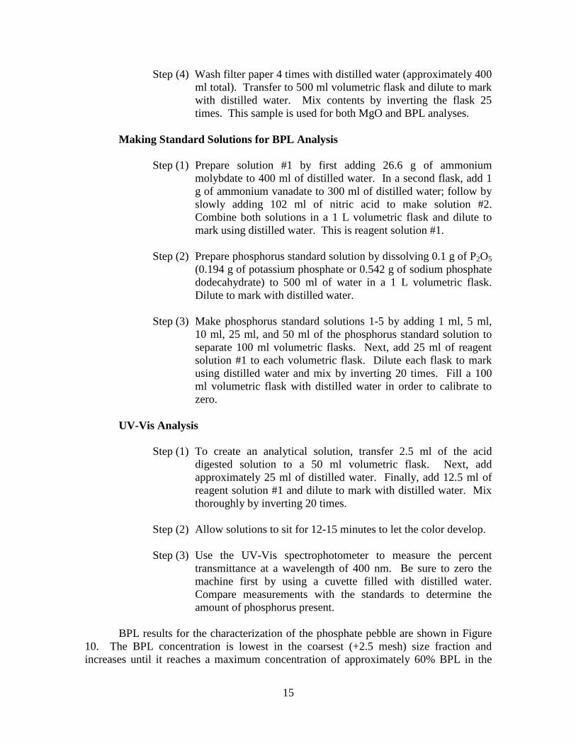
Step (4) Wash filter paper 4 times with distilled water (approximately 400 ml total). Transfer to 500 ml volumetric flask and dilute to mark with distilled water. Mix contents by inverting the flask 25 times. This sample is used for both MgO and BPL analyses.
Making Standard Solutions for BPL Analysis
Step (1) Prepare solution #1 by first adding 26.6 g of ammonium molybdate to 400 ml of distilled water. In a second flask, add 1 g of ammonium vanadate to 300 ml of distilled water; follow by slowly adding 102 ml of nitric acid to make solution #2. Combine both solutions in a 1 L volumetric flask and dilute to mark using distilled water. This is reagent solution #1.
Step (2) Prepare phosphorus standard solution by dissolving 0.1 g of P2O5
(0.194 g of potassium phosphate or 0.542 g of sodium phosphate dodecahydrate) to 500 ml of water in a 1 L volumetric flask. Dilute to mark with distilled water.
Step (3) Make phosphorus standard solutions 1-5 by adding 1 ml, 5 ml,
10 ml, 25 ml, and 50 ml of the phosphorus standard solution to separate 100 ml volumetric flasks. Next, add 25 ml of reagent solution #1 to each volumetric flask. Dilute each flask to mark using distilled water and mix by inverting 20 times. Fill a 100 ml volumetric flask with distilled water in order to calibrate to zero.
UV-Vis Analysis
Step (1) To create an analytical solution, transfer 2.5 ml of the acid digested solution to a 50 ml volumetric flask. Next, add approximately 25 ml of distilled water. Finally, add 12.5 ml of reagent solution #1 and dilute to mark with distilled water. Mix thoroughly by inverting 20 times.
Step (2) Allow solutions to sit for 12-15 minutes to let the color develop. Step (3) Use the UV-Vis spectrophotometer to measure the percent
transmittance at a wavelength of 400 nm. Be sure to zero the machine first by using a cuvette filled with distilled water. Compare measurements with the standards to determine the amount of phosphorus present.
BPL results for the characterization of the phosphate pebble are shown in Figure 10. The BPL concentration is lowest in the coarsest (+2.5 mesh) size fraction and increases until it reaches a maximum concentration of approximately 60% BPL in the

16
6×8 mesh size fraction. BPL concentration then decreases slightly in the finer size fractions (12×14 and -14 mesh) due to the increase in dolomite and silica fines.
0.0%
10.0%
20.0%
30.0%
40.0%
50.0%
60.0%
70.0%
%BP
L
Size Fraction (Tyler Mesh)
%BPL Analysis
Figure 10. BPL Analysis of High-MgO Phosphate Pebble. Carbonate Analysis Carbonate analysis of phosphate pebble is important not only because dolomite (MgCa(CO3)2) is a carbonate mineral, but also because the phosphate is a carbonate-rich apatite (francolite). Carbonate concentrations were determined using thermogravimetric analysis (TGA). TGA measures changes in weight in relation to a change in temperature. In the case of dolomite, there are two specific reactions involved in the evolution of CO2 gas resulting in weight loss of the sample. The two reactions occur over a temperature range of 450-900o C (Duval 1963):
Reaction (1): MgCa(CO3)2(s) → CO2(g) + MgO(s) + CaCO3(s) 450-710o C
Reaction (2): MgO(s) + CaCO3(s) → CO2(g) + MgO(s) + CaO(s) 710-820o C Figure 11 shows an example of results from the thermogravimetric analysis of the +2.5 mesh size fraction. For this particular ore, reaction (1) begins at approximately 450o
C and ends around 710o C. Reaction (2) follows directly after reaction (1) and finishes at

17
a temperature around 820o C. Total change in weight over the CO2-producing reactions was 12.6%. This equates to a carbonate concentration of 17.2%. The TGA used for carbonate analysis was a Leco TGA 701 thermogravimetric analyzer, which is shown in Figure 12. TGA was performed on all size fractions of the high-MgO phosphate ore, with the TGA curves shown in Figure 13. Carbonate concentrations for each size fraction were calculated and can been seen in Figure 14. Carbonate concentrations are greatest in the coarsest (+2.5 mesh) size fraction and decrease until a minimum of approximately 3.7% is reached in the 10×12 mesh size fraction. The finer size fractions (12×14 and -14 mesh) then show a slight increase in CO3 due to the accumulation of dolomite fines in the finest size fraction.
80.0%
85.0%
90.0%
95.0%
100.0%
0 200 400 600 800 1000
% of
Initi
al To
tal W
eigh
t
Temperature (oC)
Characterization of High-MgO Phosphate Pebble -- CO3 Analysis
+2.5M (T1)
+2.5M (T2)
Reaction (1)
Reaction (2)
12.6 %Wt. Loss
Figure 11. Diagram Showing TGA of High-Dolomite Phosphate Ore (+2.5M Size
Fraction).

18
Figure 12. Leco TGA701 Thermogravimetric Analyzer Used for Carbonate
Analysis.
80.0%
85.0%
90.0%
95.0%
100.0%
0 100 200 300 400 500 600 700 800 900 1000
% o
f Ini
tial T
otal
Wei
ght
Temperature (oC)
TGA of High-MgO Phosphate Pebble -- CO3 Analysis
+2.5M
2.5x3M
3x4M
4x5M
5x6M
6x8M8x10M
-14M12x14M
10x12M
Figure 13. TGA Results for All Size Fractions of High-MgO Phosphate Ore.

19
0.0%
2.0%
4.0%
6.0%
8.0%
10.0%
12.0%
14.0%
16.0%
18.0%
20.0%%
CO3
Size Fraction (Tyler Mesh)
% CO3 Analysis
Figure 14. Carbonate (CO3) Analysis of High-MgO Phosphate Ore. Liberation Analysis
A liberation analysis was performed on the high-MgO phosphate ore by analyzing MgO content of single pebbles from the +3 mesh and 3×6 mesh size fractions. Twenty pebbles were randomly selected from each size fraction and analyzed for MgO. Results are presented in Figure 15 as a histogram. Pure dolomite contains approximately 21.8% MgO. The histogram shows that pebbles contain either very large amounts of MgO or very small amounts of MgO, indicating that the dolomite and the phosphate are well-liberated.

20
0
5
10
15
20
25
30
0-1
1-2
2-3
3-4
4-5
5-6
6-7
7-8
8-9
9-10
10-1
1
11-1
2
12-1
3
13- 1
4
14-1
5
15-1
6
16- 1
7
17-1
8
18-1
9
19-2
0
20-2
1
21-2
2
Num
ber o
f Peb
bles
%MgO in Pebble
Liberation Analysis of Mosaic Phosphate Ore
Figure 15. Histogram Results of Liberation Analysis for High-MgO Phosphate Ore. Removal of MgO by Sizing The most significant conclusion from the characterization of the first shipment of high-MgO phosphate pebble is that MgO concentration decreases with natural particle size. This occurrence presents the opportunity to reject a significant amount of MgO by a screening process. Figure 16 shows the % of MgO removed and % BPL recovered by sizing. Optimal removal by sizing occurs when removing the +4 mesh size fraction, resulting in the removal of 54% of the weight of the MgO while recovering approximately 75% of the BPL.

21
0%
10%
20%
30%
40%
50%
60%
70%
80%
90%
100%
Tyler Screen Size
Cumulative %MgO RemovedCumulative %BPL Recovered
Figure 16. MgO Rejection Versus BPL Recovery for a Screening Process. Confirmation of Analytical Methods
Periodically samples were sent out to a phosphate industry lab to confirm MgO and BPL analysis completed at Michigan Tech. Comparison of MgO results from Michigan Tech and an industry lab are shown below in Figure 17. MgO results are in good agreement with industrial analyses. BPL results were also compared and can be found below in Figure 18. BPL results are also in good agreement with industrial analyses.

22
0.00%
0.50%
1.00%
1.50%
2.00%
2.50%
3.00%
3.50%
4.00%
4.50%
5.00%
0.00% 1.00% 2.00% 3.00% 4.00% 5.00%
MgO
Ana
lysis
by
Indu
stry
MgO Analysis at MTU
MgO Analysis
Figure 17. Comparison of MgO Analyses Done at MTU with Results from a
Phosphate Industry Lab.
0%
10%
20%
30%
40%
50%
60%
70%
80%
0% 10% 20% 30% 40% 50% 60% 70% 80%
BPL A
naly
sis b
y In
dust
ry
BPL analysis at MTU
BPL Analysis
Figure 18. Comparison of BPL Analyses Done at MTU with Results from a
Phosphate Industry Lab.

23
CHARACTERIZATION OF CaCl2 SOLUTION
A goal of this study was to determine how a dense fluid affects the efficiency of the jigging process. A calcium chloride (DowflakeXTRA) solution was used for the dense fluid. DowflakeXTRA was used in this study since it is significantly less expensive than reagent-grade calcium chloride. The chemical composition of DowflakeXTRA can be found below in Table 1. Density and viscosity measurements were taken at various DowflakeXTRA solution concentrations. Table 1. Chemical Composition of DowflakeXTRA as Supplied by Manufacturer.
Component Percentage Calcium chloride (CaCl2) 83-87% Potassium chloride (KCl) 2-3% Water (H2O) 8-14% Sodium chloride (NaCl) 1-2%
DowflakeXTRA Solution Density Measurements DowflakeXTRA solutions of 5%, 10%, 15%, 20%, 25%, 30%, 35%, and 40% (by weight) were created. Solution densities were determined using 20 mL pycnometers. Results are shown below in Figure 19.
0.00
0.20
0.40
0.60
0.80
1.00
1.20
1.40
1.60
0% 5% 10% 15% 20% 25% 30% 35% 40% 45%
Solu
tion
Dens
ity (g
/cm
3 )
wt.% Dowflake Solution
DowflakeXTRA Solution Density
Figure 19. Solution Density Measurements at Various DowflakeXTRA
Concentration.

24
DowflakeXTRA Solution Viscosity Measurements Solution viscosity has been noted throughout literature to have detrimental effects on gravity separation processes (Gupta and Yan 2006). Therefore, it was important to determine the viscosity of DowflakeXTRA solutions at various concentrations. Kinematic viscosity measurements were made using a Cannon Fenske viscometer (model 50). Kinematic viscosity results are shown below in Figure 20. Based on results from the density and viscosity measurements, it was determined that a CaCl2 solution between 20-25% wt. would be best. This concentration was chosen because it is the point beyond which fluid viscosity starts to drastically increase. Therefore, any possible benefits gained by an increase in fluid density beyond that point would be hindered by the significant increases in viscosity. For this study a 22% wt. CaCl2 solution was created by adding 11.8 kg of DowflakeXTRA to 8.9 gallons of tap water. The CaCl2 solution had a density of 1.20 g/cm3 and a kinematic viscosity of 1.65 cSt. The CaCl2 solution was recycled and used for all experiments in this study. Solution samples were taken before each CaCl2 jigging experiment, with density and kinematic viscosity measurements taken to ensure that the fluid maintained similar properties throughout all experiments. Figure 21 shows kinematic viscosity and density measurements for each recycle. Measurements showed no significant variations in fluid density and kinematic viscosity when recycling the CaCl2 solution.
0.00
0.50
1.00
1.50
2.00
2.50
3.00
3.50
4.00
0% 5% 10% 15% 20% 25% 30% 35% 40% 45%
Kine
mat
ic V
iscos
ity (c
St)
wt.% Dowflake Solution
Dowflake Solution Viscosity
Figure 20. Solution Kinematic Viscosity Measurements at Various DowflakeXTRA
Concentrations.

25
0.00
0.20
0.40
0.60
0.80
1.00
1.20
1.40
1.60
1.80
2.00
0 1 2 3 4 5
Dens
ity (g
/cm
3 ), K
inem
atic
Visc
osity
(cS
t)
Number of Recycles
Viscosity and Density of Recycled CaCl2 Solution
Kinematic Viscosity (cSt)
Density (g/cm3)
Figure 21. Kinematic Viscosity and Density Measurements for Each Recycle of
CaCl2 Solution.

27
EXPERIMENTAL SETUP AND DESIGN FOR JIGGING STUDIES JIG DESIGN AND OPERATION Design of Laboratory-Scale Jig
A lab-scale jig was designed and built for this study at Michigan Tech. It was desired that the jig be large enough to handle larger (4 mm) particle feeds and also be compatible with corrosive fluids. Other jig specifications included making a jig that could be operated as a batch or continuous (or semi-continuous) process and have easily varied jigging parameters.
Figure 22 shows a photo of the jig used for this study. The main body of the jig is constructed out of 4” PVC pipe, with a 2” PVC pipe for the pulsation arm. A plunger and controller were used to control pulsation frequency. The stroke length could be changed by moving the pulsation arm out radially. Feed rate was controlled by a vibratory feeder with a hopper that could hold approximately 4 kg of ore.
Figure 22. Photo of Large Laboratory-Scale Jig.
Supplemental water was added at the bottom of the jig through the hutch to aid in fluidization of the particle bed. This hutch water flow was provided by a chemical-resistant magnetic drive pump with appropriate valves for flow control. A rotameter was calibrated and used to ensure precise and accurate flows during each experiment. A plastic 55 gallon drum was used to store the jigging fluid.

28
The jig included interchangeable screens so that the screen apertures could be changed, and a feed gate to allow continuous operation. The use of unions for assembly allowed the screen to be changed easily, and also to modify the jig as desired. The feed gate was added to ensure that the feed ore reached the middle of the jig bed instead of simply moving across the top of the jig bed. A full diagram of the experimental setup is shown in Figure 23.
Feed (vibratory feeder)
Phosphate Concentrate
Dolomite-rich Rejects
Ragging
Screen
Rotameter
Magnetic Drive Pump
Pulsation Piston
Jigging Fluid Storage
Figure 23. Laboratory Jig Complete Experimental Setup. Design of Smaller-Scale Laboratory Jig
A smaller-scale U-shaped jig was built to allow for more trials to be completed while using smaller quantities of jigging fluid and feed ore. The U-shaped jig was made out of 2” diameter PVC pipe, so it was also corrosion-resistant. Figure 24 shows a photo of the small-scale U-shaped jig. A plunger was used as the pulsation mechanism and pulsation frequency was controlled by the variable speed controller. There was a valve at the bottom of the jig that could be used for the addition of hutch water flow.
Since the U-shaped jig was significantly smaller than the larger laboratory-scale jig (2” diameter as opposed to 4” diameter), the feed ore needed to be kept to a relatively small size (less than 6 mesh). Also, the smaller U-shaped jig could only be used for batch-scale jigging tests as it did not have a large container for collecting the dense particle concentrate in the hutch.

29
Figure 24. Smaller U-Shaped Laboratory-Scale Jig. Batch Jigging Procedure A batch-scale jigging procedure was initially used to determine the optimum pulsation frequency for removing dolomite from high-MgO phosphate ore. Batch-scale jigging is similar to an “over the screen” jigging process, where particle segregation occurs on top of the screen.
For batch-scale testing, the jig was first filled with the desired amount of ore. After all jigging parameters were set; the jig was run for 1 minute. Results were analyzed by separating the jig bed into Zones 1 through 4, as shown below in Figure 25. Each zone was analyzed for MgO. Similar procedures can be used when using the smaller-scaled U-shaped jig for batch jigging trials.
Zone 1Zone 2Zone 3Zone 4
Screen
Figure 25. Jig Top Broken Down into Four Zones.

30
Continuous Jigging Procedure A continuous jigging process was developed in order to more accurately simulate an industrial jigging process while testing critical jigging parameters. The continuous jigging method used is a “through the screen” jigging process, where dense particles are allowed to penetrate through the screen. “Through the screen” jigging was selected due to the difficulty of implementing and controlling a small-scale “gate and dam” system for “over the screen” jigging. Figure 26 shows the differences between “over the screen” and “through the screen” jigging processes. In a “through the screen” jigging process, all particles in the feed are smaller than the screen opening and have a chance to be collected in the dense particle concentrate.
Ragging is a layer of coarse dense particles that sit on top of the screen (Figure 27) and hinder particle movement. This prevents particles from simply entering the jig and immediately falling into the hutch. The size ratio (Equation 2), where df is the diameter of the fine particle (coarsest feed particle) and dc is the diameter of the coarse particle (ragging), is used to determine an appropriate ragging size that will allow particles to pass into the hutch. Due to geometric considerations, the theoretical size ratio limit for interstitial penetration of fines is 0.41 (Mukherjee and Mishra 2006). This would mean that a ragging diameter greater than 2.43 times that of the coarsest particle in the feed should be used.
Size ratio = f
c
dd
(2)
A vibratory feeder was used to control the feed rate for the continuous jigging
process. First, the jig was filled with the desired amount of ragging balls. Next, 300 g of feed ore was added to the jig bed. After setting the feed rate, pulsation rate, hutch water flow rate, and stroke length, the jig was run until the feed hopper was empty. Three samples were collected for analysis: (1) dense particle concentrate (hutch); (2) middlings; and (3) light particle concentrate (overs).

31
Figure 26. Comparison of "Over the Screen" and "Through the Screen" Jigging
Processes.
Ragging
Figure 27. Diagram Describing the Function of Ragging in the Jigging Process. OPTIMIZATION OF JIGGING PARAMETERS Optimization of Pulsation Rate
In literature, it has been stated that pulsation frequency is the second most important jigging parameter aside from feed rate (Mukherjee and Mishra 2006). A set of jigging tests were run to find the optimal pulsation rate for removing dolomite from Mosaic’s phosphate ore. Pulsation frequencies of 100, 200, and 300 pulsations/minute

32
were tested. The stroke length was 1”, and tap water was used as the jigging fluid at a hutch water flow rate of 0.5 gpm. Tests were run in triplicate for reproducibility. Optimization of Stroke Length and Hutch Water Flow Rate While pulsation frequency is the most important jigging parameter, stroke length and hutch water flow rate also play an important role in determining the efficiency of the jigging process. Tests were run using a continuous jigging process to determine an optimal stroke length and hutch water flow rate. Stroke lengths of 1”, 1.25”, 1.5”, and 1.75” were tested at a low hutch water flow rate of 0.5 gpm, and also at a high hutch water flow rate of 1.5 gpm. Feed rate was kept constant for these experiments. The feed ore used in these experiments was a coarser high-MgO phosphate ore that was crushed and sized to 6×20 mesh. The feed ore averaged 2.15% MgO. Table 2. Experimental Design for Optimization of Stroke Length and Hutch Water
Flow Rate.
Experiment # Stroke Length (Inches)
Hutch Water Flow Rate (gpm)
1.1 1” 0.5 1.2 1” 1.5 2.1 1.25” 0.5 2.2 1.25” 1.5 3.1 1.5” 0.5 3.2 1.5” 1.5 4.1 1.75” 0.5 4.2 1.75” 1.5
Effects of Ragging Density Ragging is an important factor in the efficient operation of the jigging process. Therefore, a complete understanding of ragging parameters is essential for proper optimization of the jigging process. All of the following ragging properties will affect the performance of the jigging process: (1) size; (2) shape; and (3) density. As previously discussed, a minimum ragging size of 2.43 times that of the coarsest feed particle is needed for penetration of fines (Mukherjee and Mishra 2006). Ragging shape can significantly lower the voidage, and therefore significantly limit the ability for fine particles to penetrate into the dense particle concentrate. For that reason, spherical ragging balls were used in all jigging experiments to eliminate variations due to particle shape. Finally, ragging density was the focus of this set of experiments. Two different ragging materials of the same size (10 mm dia.) were used: (1) Stainless steel balls (S.G.≈7.9 g/cm3) (2) Alumina (99.5%) balls (S.G. ≈3.5 g/cm3)

33
Table 3 shows the experimental design for this set of experiments. Table 4 shows the relevant jigging parameters. Average MgO content in the feed was 1.37%. Each experiment was run in triplicate for reproducibility. Table 3. Experimental Design for Ragging Density Experiments.
Experiment No. Feed Rate Ragging
Density 1 - - 2 - + 3 + - 4 + +
Table 4. Jigging Parameters Used in Ragging Density Experiments.
Parameter Value Pulsation rate 200 pulses/minute Stroke length 1 inch Hutch water flow rate 0.5 gpm Feed Uncrushed phosphate ore Feed size 5×20 mesh No. of ragging balls 200 balls (depth of 2.5-3 ragging layers)
JIGGING WITH DIFFERENT PHOSPHATE FEEDS Crushed Higher-MgO Feed It was desired that it be determined how the jigging process would perform using higher-MgO phosphate ore feeds, therefore a second shipment of phosphate ore was requested and received. The ore was considerably coarser than the first shipment and was consequently crushed and sized to 6×20 mesh to be consistent with previous experiments. The crushed higher-MgO feed had an average MgO content of 2.05%. A continuous jigging procedure was used for this set of experiments. Six experiments in total were run under the conditions shown in Table 5. Table 5. Jigging Parameters for Higher-MgO Experiments.
Parameter Value Pulsation rate 200 pulse/min. Hutch water flow rate 0.5 gpm Stroke length 1" Ragging material 3/8" steel balls Feed size -6/+20 mesh crushed high-MgO feed

34
Uncrushed Higher-MgO Feed
An additional high-MgO phosphate ore was also received from CF Industries to be tested with the optimized jigging parameters. A 5 gallon bucket of uncrushed high-MgO phosphate pebble was sized to 6×20 mesh and split for use as feed material. Characterization results are shown in table 6. The uncrushed high-MgO feed had an average MgO content of 3.00%.
A continuous jigging testing procedure was used to determine the efficiency of the jigging process using the uncrushed phosphate ore. Table 7 shows important jigging parameters. Experiments were run at a high (≈300 g/min.) and low (≈170 g/min.) feed rates. Due to the limited amount of feed ore, two tests were run for reproducibility.
After completing the water jigging experiment, the 6×20 mesh CF Industries phosphate ore was remixed and used for preliminary dense fluid jigging experiments. One experiment was completed using a CaCl2 solution along with the optimized jigging parameters at a high (≈455 g/min.) feed rate. The CaCl2 solution had a solution density of approximately 1.20 g/cm3 and a kinematic viscosity of 1.73 cSt. Table 6. Characterization of CF Industries Phosphate Ore.
Size Fraction Weight % % MgO % BPL +6M 18.23% 8.40% 17.48%
6×10M 32.75% 4.19% 40.47% 10×14M 28.07% 2.54% 49.72% 14×20M 15.18% 2.29% 51.19%
-20M 5.77% 3.51% 29.71% Table 7. Jigging Parameters Used for Uncrushed High-MgO Phosphate Ore
Experiments.
Parameter Value Pulsation rate 200 pulses/minute Stroke length 1" Hutch water flow rate 0.75 gpm Feed ore 6×20 mesh uncrushed CF Industries
high-MgO phosphate pebble Ragging Alumina balls (10 mm dia.)
35
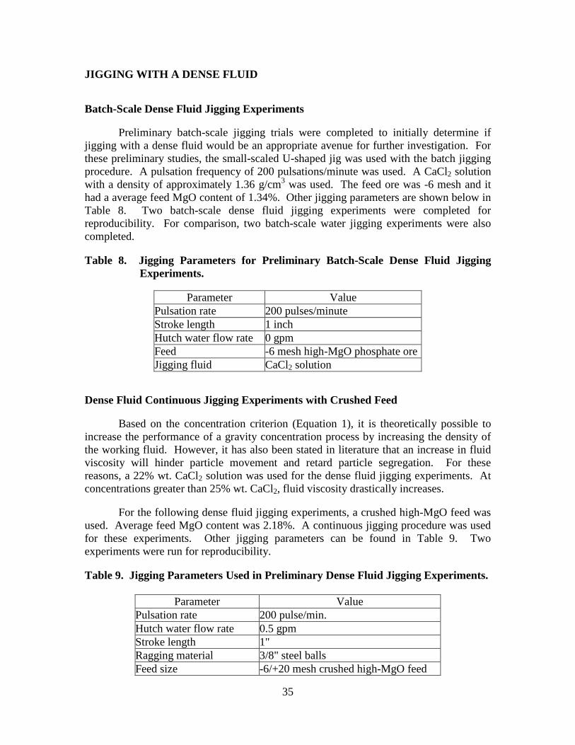
JIGGING WITH A DENSE FLUID Batch-Scale Dense Fluid Jigging Experiments Preliminary batch-scale jigging trials were completed to initially determine if jigging with a dense fluid would be an appropriate avenue for further investigation. For these preliminary studies, the small-scaled U-shaped jig was used with the batch jigging procedure. A pulsation frequency of 200 pulsations/minute was used. A CaCl2 solution with a density of approximately 1.36 g/cm3 was used. The feed ore was -6 mesh and it had a average feed MgO content of 1.34%. Other jigging parameters are shown below in Table 8. Two batch-scale dense fluid jigging experiments were completed for reproducibility. For comparison, two batch-scale water jigging experiments were also completed. Table 8. Jigging Parameters for Preliminary Batch-Scale Dense Fluid Jigging
Experiments.
Parameter Value Pulsation rate 200 pulses/minute Stroke length 1 inch Hutch water flow rate 0 gpm Feed -6 mesh high-MgO phosphate ore Jigging fluid CaCl2 solution
Dense Fluid Continuous Jigging Experiments with Crushed Feed Based on the concentration criterion (Equation 1), it is theoretically possible to increase the performance of a gravity concentration process by increasing the density of the working fluid. However, it has also been stated in literature that an increase in fluid viscosity will hinder particle movement and retard particle segregation. For these reasons, a 22% wt. CaCl2 solution was used for the dense fluid jigging experiments. At concentrations greater than 25% wt. CaCl2, fluid viscosity drastically increases. For the following dense fluid jigging experiments, a crushed high-MgO feed was used. Average feed MgO content was 2.18%. A continuous jigging procedure was used for these experiments. Other jigging parameters can be found in Table 9. Two experiments were run for reproducibility. Table 9. Jigging Parameters Used in Preliminary Dense Fluid Jigging Experiments.
Parameter Value Pulsation rate 200 pulse/min. Hutch water flow rate 0.5 gpm Stroke length 1" Ragging material 3/8" steel balls Feed size -6/+20 mesh crushed high-MgO feed

36
JIGGING WITH A DENSE FLUID—FACTORIAL EXPERIMENTS The goal of this study was to determine how jigging with a dense fluid affects the efficiency of the jigging process for the removal of dolomite from high-MgO phosphate ore. It is stated in literature that feed rate is the most important jigging parameter, with the second most important parameter being pulsation frequency (Mukherjee and Mishra 2006). In previous studies by the investigators it was determined that a pulsation rate of 200 pulsations/minute was optimal for this separation. For this set of experiments, a 2×2 factorial design was constructed with feed rate and jigging fluid being the varied parameters. A high feed (~160 g/min.) and a low feed rate (~55 g/min.) were used. For the jigging fluid, tap water (S.G.≈1 g/cm3) and a CaCl2 solution (S.G.≈1.20 g/cm3) were used. Experiments were run in triplicate at each condition, as shown in Table 10. Other jigging parameters that were kept constant can be found in Table 11. Table 10. Experimental Design for Dense Fluid Jigging Studies.
Experiment No. Feed Rate Jigging Fluid
1.1 Low Water 1.2 Low Water 1.3 Low Water 2.1 High Water 2.2 High Water 2.3 High Water 3.1 Low CaCl2 soln. 3.2 Low CaCl2 soln. 3.3 Low CaCl2 soln. 4.1 High CaCl2 soln. 4.2 High CaCl2 soln. 4.3 High CaCl2 soln.
Table 11. Jigging Parameters for Dense Fluid Jigging Studies.
Parameter Value Pulsation frequency 200 pulsations/min. Hutch flow 0.5 gpm Pulsation stroke 1” Ragging 10 mm alumina balls (200 balls) Feed ore 5×20 mesh uncrushed phosphate
ore

37
RESULTS AND DISCUSSION OF JIGGING EXPERIMENTS JIG OPTIMIZATION RESULTS Optimization of Pulsation Rate in Batch Experiments
Pulsation rate is one of the most important jigging parameters. If the pulsation frequency is too fast, particles will not have time to segregate. If the pulsation rate is too slow, the pulsation stroke will not be strong enough to fluidize the jig bed, resulting in no separation. Pulsation rates of 100, 200, 300 pulsations/minute were tested using a batch jigging procedure.
Tabulated results from the pulsation rate studies can be seen in Table 12, including % MgO content and % weight recovery for each zone. Higher pulsation rates of 200 and 300 pulses/minute showed significantly better results than the lower pulsation rates. Results were also plotted as MgO rejection curves, which can be seen below in Figure 28. Graphically, it shows that higher pulsation rates of 200 and 300 pulses/minute gave the best results as they removed more MgO while removing less of the total weight. Pulsation rates greater than 300 resulted in turbulent flow through the jig bed and an uneven pulsation across the jig bed. The best separation occurred during Trial 2 at a pulsation rate of 300 pulses/minute, where the greatest MgO rejection was achieved, resulting in a phosphate concentrate containing 1.57 % MgO at 26.11% weight recovery. Based on these results, a pulsation frequency of 200 pulsations/minutes was chosen as the optimal pulsation rate for future experiments.
0%
10%
20%
30%
40%
50%
60%
70%
80%
90%
100%
0% 10% 20% 30% 40% 50% 60% 70% 80% 90% 100%
Wei
ght %
Rej
ecte
d
% of Total MgO Removed
Pulsation Rate Jigging Results
PR100PR200PR300
Figure 28. Results from Pulsation Rate Optimization Experiments Plotted as MgO
Rejection Curves.

38
Table 12. Pulsation Rate Optimization Results Corresponding to Figure 28.
Pulsation Rate – 100 pulse/min. T1 T2 T3
Zone % MgO % Weight % MgO % Weight % MgO % Weight 4 3.71 20.92 4.18 20.58 4.04 20.73 3 3.89 25.47 2.88 26.27 3.51 25.53 2 3.64 26.58 3.70 29.06 2.88 26.64 1 2.82 27.03 3.14 24.09 2.88 27.09
Calc. Feed 3.49 100 3.45 100 3.28 100
Pulsation Rate – 200 pulse/min. T1 T2 T3
Zone % MgO % Weight % MgO % Weight % MgO % Weight 4 3.85 16.96 3.83 20.58 3.98 20.92 3 4.09 19.99 4.07 26.27 4.48 25.47 2 4.18 29.01 3.57 29.06 3.11 26.58 1 2.01 34.04 1.75 24.09 1.88 27.03
Calc. Feed 3.37 100 3.32 100 3.31 100
Pulsation Rate – 300 pulse/min. T1 T2 T3
Zone % MgO % Weight % MgO % Weight % MgO % Weight 4 4.06 15.19 3.59 18.46 4.29 25.51 3 4.37 17.10 3.89 24.81 3.67 23.55 2 4.16 28.56 3.44 30.61 3.99 25.82 1 2.30 39.15 1.57 26.11 1.80 25.12
Calc. Feed 3.45 100 3.09 100 3.44 100 Optimization of Stroke Length and Hutch Water Flow Rate Continuous jigging tests were run at four different stroke lengths (1”, 1.25”, 1.5’, and 1.75”) and two different hutch water flow rates (0.5 gpm and1.5 gpm). Results are shown below in Figure 29 as % weight recovery vs. % MgO in the dense particle concentrate. At these conditions, the stroke length had a significantly greater affect on recovery than hutch water flow rate. Furthermore, longer stroke lengths resulted in a larger fraction of the feed going into the hutch. Based on these results, 1” was chosen as the optimal stroke length for future testing.

39
0.0%
20.0%
40.0%
60.0%
80.0%
100.0%
0.50% 1.00% 1.50% 2.00% 2.50%
% W
eigh
t Rec
over
y in
Phos
phat
e Co
ncen
trat
e
%MgO in Phosphate Concentrate
% Weight Recovery vs. %MgO in Phosphate Concentrate
0.5 gpm hutch water flow rate
1.5 gpm hutch water flow rate
1"
1.25"
1.75"1.5"
1.75"1.25"
1"
1"
1.5"
1"
Figure 29. Effects of Stroke Length and Hutch Water Flow Rate on Jigging Process. Effect of Ragging Density in Continuous Jigging
Results from ragging density experiments can be found below in Figure 30. As anticipated, results show a general trend of decreasing MgO content with decreasing BPL recovery. The best results came from Trial 4, where a phosphate concentrate containing 0.88% MgO with a BPL recovery of 53.48% was achieved. It is apparent from the grade vs. recovery curve that feed rate has a large effect on recovery. For experiments conducted at the slower feed rate (Experiments #2 and #4), a wide range of recoveries were obtained, this can be attributed to the fairly wide 5×20M feed size range. A larger particle will penetrate through the ragging slower than a finer particle. If the feed had become segregated by size in the feed hopper during continuous experiments, more of the larger particles could be fed to the jig during the beginning of the experiment. This would result in a lower dense particle recovery at the start of the experiment. Conversely, if finer particles were fed to the jig in the beginning of the experiment, a higher dense particle recovery would be obtained. For this reason, much attention was put on making sure the feed was thoroughly mixed before being put into the vibratory feed hopper.

40
Overall, it does not appear that ragging density has a significant effect on the jigging process at these conditions. However, it is possible that performance would change if the ragging was only slightly denser than the high-density apatite particles. Possible options for lower-density ragging would include glass beads or hollow balls of various materials.
0%
10%
20%
30%
40%
50%
60%
70%
80%
90%
100%
0.00% 0.20% 0.40% 0.60% 0.80% 1.00% 1.20% 1.40%
% B
PL R
ecov
ered
%MgO in Phosphate Concentrate
Grade vs. Recovery
Experiment #1 [Feed rate (+), Ragging density (-)]
Experiment #2 [Feed rate (-), Ragging density (-)]
Experiment #3 [Feed rate (+), Ragging density (+)]
Experiment #4 [Feed rate (-), Ragging density (+)]
Figure 30. Grade Versus Recovery Curve for Ragging Density Experiments. JIGGING WITH DIFFERENT PHOSPHATE FEEDS Crushed Higher-MgO Feed
In general, for a process to be considered as a promising method for the removal of MgO from phosphate ores, it is desired that the process perform well with many different ore bodies. However, as is the case with any separation process, performance is going to vary depending on the feed ore. For this reason, different feed ores were tested with the jigging process. Results from experiments conducted with a crushed higher-MgO phosphate ore are shown below in Figure 31. The best results came from Experiment #4, where a concentrate containing 0.84% MgO was achieved, with a BPL recovery of 55.4%. The
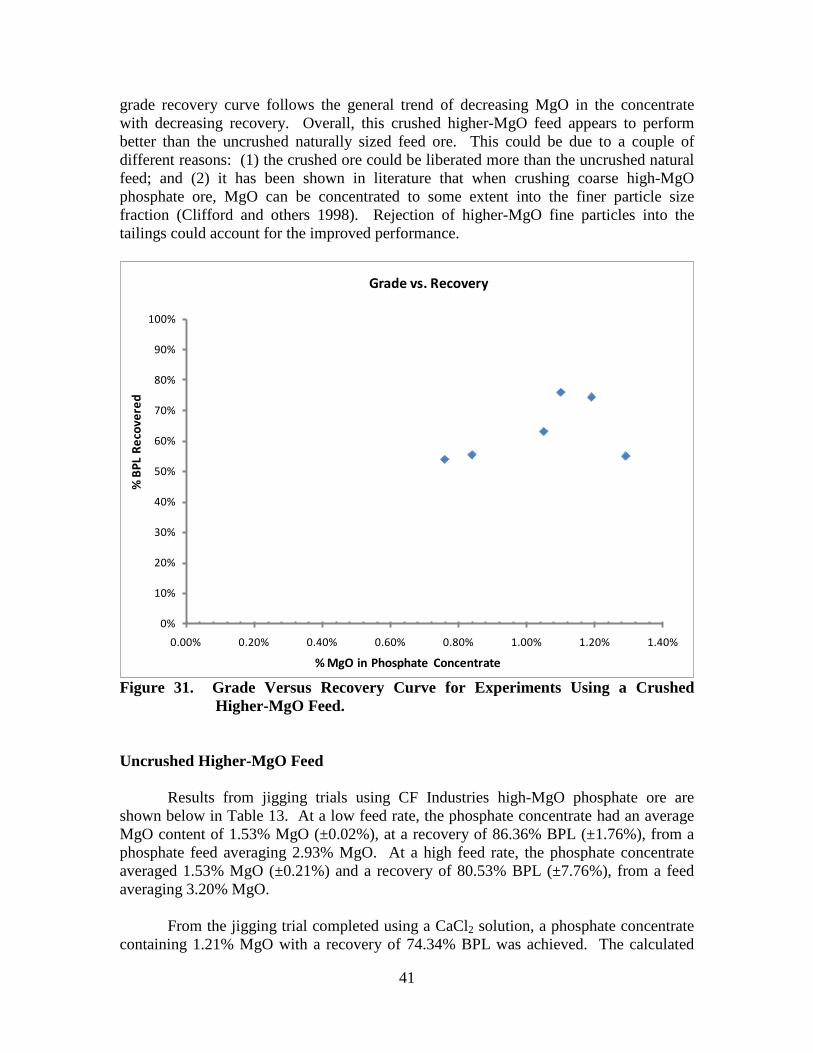
41
grade recovery curve follows the general trend of decreasing MgO in the concentrate with decreasing recovery. Overall, this crushed higher-MgO feed appears to perform better than the uncrushed naturally sized feed ore. This could be due to a couple of different reasons: (1) the crushed ore could be liberated more than the uncrushed natural feed; and (2) it has been shown in literature that when crushing coarse high-MgO phosphate ore, MgO can be concentrated to some extent into the finer particle size fraction (Clifford and others 1998). Rejection of higher-MgO fine particles into the tailings could account for the improved performance.
0%
10%
20%
30%
40%
50%
60%
70%
80%
90%
100%
0.00% 0.20% 0.40% 0.60% 0.80% 1.00% 1.20% 1.40%
% B
PL R
ecov
ered
% MgO in Phosphate Concentrate
Grade vs. Recovery
Figure 31. Grade Versus Recovery Curve for Experiments Using a Crushed
Higher-MgO Feed. Uncrushed Higher-MgO Feed
Results from jigging trials using CF Industries high-MgO phosphate ore are shown below in Table 13. At a low feed rate, the phosphate concentrate had an average MgO content of 1.53% MgO (±0.02%), at a recovery of 86.36% BPL (±1.76%), from a phosphate feed averaging 2.93% MgO. At a high feed rate, the phosphate concentrate averaged 1.53% MgO (±0.21%) and a recovery of 80.53% BPL (±7.76%), from a feed averaging 3.20% MgO.
From the jigging trial completed using a CaCl2 solution, a phosphate concentrate containing 1.21% MgO with a recovery of 74.34% BPL was achieved. The calculated

42
feed MgO for the CaCl2 jigging trial was 2.75% MgO. Grade versus recovery curves for both trials are shown in Figure 32. Table 13. Results for Uncrushed Higher-MgO Phosphate Feed Experiments.
Trial # Conditions Sample %
MgO %
BPL %
Weight
% MgO
Recov.
% BPL
Recov.
% Calc. Feed MgO
% Calc. Feed BPL
Total Time
(Min:Sec)
CF1.1 Water - low feed rate
Dolomite-rich tailings 8.63 16.57 17.0 49.38 6.63
2.97 42.47 10:19 Middlings 4.26 42.99 8.2 11.70 8.25
Phosphate concentrate 1.54 48.29 74.9 38.93 85.11
CF1.2 Water - low feed rate
Dolomite-rich tailings 8.92 17.09 16.0 49.25 5.96
2.89 45.73 9:42 Middlings 4.38 43.25 6.8 10.32 6.44
Phosphate concentrate 1.51 51.87 77.2 40.43 87.60
CF2.1 Water - high feed rate
Dolomite-rich tailings 7.34 30.55 27.7 64.04 16.07
3.18 52.73 5:49 Middlings 2.95 53.03 9.2 8.53 9.24
Phosphate concentrate 1.38 62.43 63.1 27.43 74.69
CF2.2 Water - high feed rate
Dolomite-rich tailings 8.58 22.17 19.9 52.89 8.71
3.22 50.60 5:25 Middlings 4.47 44.18 6.4 8.93 5.62
Phosphate concentrate 1.67 58.82 73.7 38.18 85.67
CF3.1
CaCl2 solution - high feed rate
Dolomite-rich tailings 6.12 34.78 28.0 62.30 19.14
2.75 50.80 3:44 Middlings 3.59 47.47 7.0 9.11 6.52
Phosphate concentrate 1.21 58.04 65.1 28.59 74.34

43
0%
10%
20%
30%
40%
50%
60%
70%
80%
90%
100%
0.00% 0.50% 1.00% 1.50% 2.00% 2.50% 3.00%
% B
PL R
ecov
ered
%MgO in Phosphate Concentrate
Water - Low Feed Rate
Water - High Feed Rate
CaCl2 Solution - High Feed Rate
Figure 32. Grade Versus Recovery Curve for Uncrushed Higher-MgO Phosphate
Ore.
Figure 33. Hand-Separated CF Industries 6×20 Mesh Sample. A 6×20 mesh sample of CF Industries high-MgO phosphate ore was hand separated into three different color categories as shown in Figure 33: (1) black pebbles, (2) light grey/red pebbles, and (3) light yellow pebbles. It was determined using atomic absorption analysis that the black (phosphate) pebbles contained an average of 1.15% MgO, while the light yellow (dolomite) pebbles contained an average of 9.17% MgO. This indicates that the lowest attainable MgO level is approximately 1.15% MgO.

44
JIGGING WITH A DENSE FLUID Preliminary Batch-Scale Dense Fluid Jigging Experiments
Results from the preliminary batch-scale dense fluid jigging experiments are shown below in Table 14. Figure 34 shows the results plotted as % of total MgO removed versus % weight rejected. Results indicate that the best results came from Trial 1 using a dense jigging fluid. Also, results showed that when using a dense fluid more ore was collected in the hutch than when using water. It was decided that the next step would be to determine how the dense fluid jigging process would perform on a larger-scale, continuous jigging process. Table 14. Results from Preliminary Batch-Scale Jigging Trials with a Dense Fluid. Water-T1 Water-T2 CaCl2 Solution-T1 CaCl2 Solution-T2
% MgO Weight % % MgO Weight % % MgO Weight % % MgO Weight % Tops 2.09 14.8 1.79 16.9 1.71 16.1 1.68 14.0 Middles 1.77 24.5 1.63 20.0 1.78 17.0 1.62 22.4 Bottoms 1.20 54.6 1.22 58.2 1.06 55.4 1.20 51.8 Hutch 0.83 6.1 0.68 4.9 0.60 11.5 0.69 11.8 Calc. Feed 1.45 100 1.37 100 1.23 100 1.30 100
0.0%
10.0%
20.0%
30.0%
40.0%
50.0%
60.0%
70.0%
80.0%
90.0%
100.0%
0.0% 10.0% 20.0% 30.0% 40.0% 50.0% 60.0% 70.0% 80.0% 90.0% 100.0%
Wei
ght %
Rej
ecte
d
% of Total MgO Removed
Preliminary Dense Fluid Batch Jigging Test
Water T1
Water T2
CaCl2 Solution T1
CaCl2 Solution T2
Figure 34. Total %MgO Removed Versus Weight % Rejected for Preliminary
Batch-Scale Jigging Experiments with a Dense Fluid.

45
Preliminary Dense Fluid Jigging Experiments Jigging experiments were run to examine how using a dense jigging fluid (CaCl2 solution) affected different aspects of the jigging process. Results are shown below in Figure 35. Concentrates containing 1.33%MgO and 0.84%MgO were achieved at BPL recoveries of 76.5% and 60.8%, respectively. Average MgO content in the feed was 2.18%. While running dense fluid jigging experiments, one major operational difference from jigging with water was noticed. When jigging with a dense fluid, recovery rates showed a significant increase. For the preliminary set of dense fluid jigging experiments it was desired that weight recovery in the concentrate be similar to that of previous jigging experiments (45-65%). In order to reach this desired recovery range, the feed rate was increased significantly. Average feed rates were 176.8 g/minute and 159.9 g/minute. This would indicate a significant increase in throughput over experiments with similarly sized feed ore using water as the jigging fluid. However, a more complete set of carefully controlled experiments needed to be completed to ensure that the increase in recovery (or throughput) could be attributed to the dense jigging fluid and not some other operational difference (such as gate height, insufficient mixing, or feed differences).
0%
10%
20%
30%
40%
50%
60%
70%
80%
90%
100%
0.00% 0.20% 0.40% 0.60% 0.80% 1.00% 1.20% 1.40%
% B
PL R
ecov
ery
% MgO in Phosphate Concentrate
Grade vs. Recovery
Figure 35. Grade Versus Recovery Curve for Preliminary Dense Fluid Jigging Experiments.
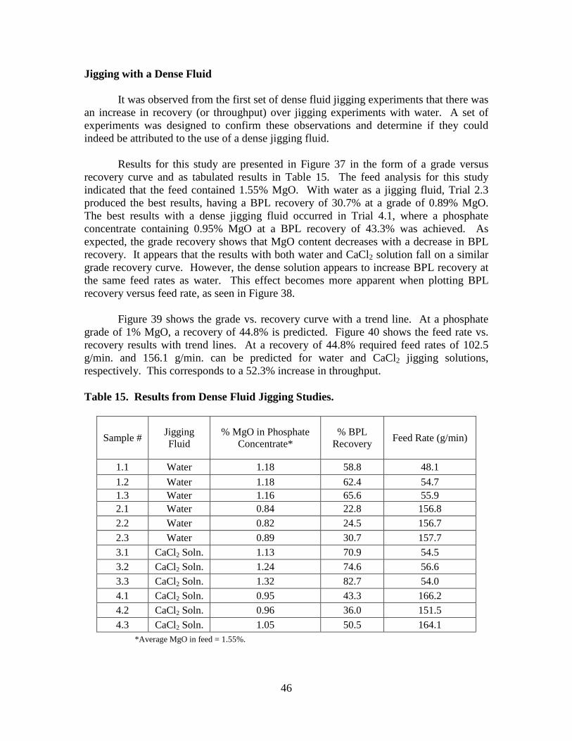
46
Jigging with a Dense Fluid
It was observed from the first set of dense fluid jigging experiments that there was an increase in recovery (or throughput) over jigging experiments with water. A set of experiments was designed to confirm these observations and determine if they could indeed be attributed to the use of a dense jigging fluid.
Results for this study are presented in Figure 37 in the form of a grade versus recovery curve and as tabulated results in Table 15. The feed analysis for this study indicated that the feed contained 1.55% MgO. With water as a jigging fluid, Trial 2.3 produced the best results, having a BPL recovery of 30.7% at a grade of 0.89% MgO. The best results with a dense jigging fluid occurred in Trial 4.1, where a phosphate concentrate containing 0.95% MgO at a BPL recovery of 43.3% was achieved. As expected, the grade recovery shows that MgO content decreases with a decrease in BPL recovery. It appears that the results with both water and CaCl2 solution fall on a similar grade recovery curve. However, the dense solution appears to increase BPL recovery at the same feed rates as water. This effect becomes more apparent when plotting BPL recovery versus feed rate, as seen in Figure 38.
Figure 39 shows the grade vs. recovery curve with a trend line. At a phosphate grade of 1% MgO, a recovery of 44.8% is predicted. Figure 40 shows the feed rate vs. recovery results with trend lines. At a recovery of 44.8% required feed rates of 102.5 g/min. and 156.1 g/min. can be predicted for water and CaCl2 jigging solutions, respectively. This corresponds to a 52.3% increase in throughput. Table 15. Results from Dense Fluid Jigging Studies.
Sample # Jigging Fluid
% MgO in Phosphate Concentrate*
% BPL Recovery Feed Rate (g/min)
1.1 Water 1.18 58.8 48.1 1.2 Water 1.18 62.4 54.7 1.3 Water 1.16 65.6 55.9 2.1 Water 0.84 22.8 156.8 2.2 Water 0.82 24.5 156.7 2.3 Water 0.89 30.7 157.7 3.1 CaCl2 Soln. 1.13 70.9 54.5 3.2 CaCl2 Soln. 1.24 74.6 56.6 3.3 CaCl2 Soln. 1.32 82.7 54.0 4.1 CaCl2 Soln. 0.95 43.3 166.2 4.2 CaCl2 Soln. 0.96 36.0 151.5 4.3 CaCl2 Soln. 1.05 50.5 164.1
*Average MgO in feed = 1.55%.

47
A 5×20 mesh sample of Mosaic high-MgO phosphate ore was hand-separated into four different color categories as shown in Figure 36: (1) black pebbles, (2) light gray/red pebbles, (3) light yellow pebbles, and (4) silica. It was determined using atomic absorption analysis that the black (phosphate) pebbles contained an average of 0.53% MgO, the light gray pebbles contained 1.03% MgO, and the light yellow (dolomite) pebbles contained an average of 4.65% MgO. This indicates that the lowest attainable MgO level is approximately 0.53% MgO for this specific ore.
Figure 36. Sample of High-MgO Mosaic Phosphate Ore (5×20 Mesh) Hand-
Separated into Four Different Categories: Dark Black Pebbles, Light Gray Pebbles, Light Yellow Pebbles, and Silica Pebbles.
0%
10%
20%
30%
40%
50%
60%
70%
80%
90%
100%
0.00% 0.20% 0.40% 0.60% 0.80% 1.00% 1.20% 1.40%
% B
PL R
ecov
ered
%MgO in Phosphate Concentrate
Grade vs. Recovery
WaterJigging - Low Feed Rate
Water Jigging - High Feed Rate
CaCl2 Soln Jigging - Low Feed Rate
CaCl2 Soln. Jigging - High Feed Rate
Figure 37. Grade Versus Recovery Curve for Dense Fluid Jigging Studies.
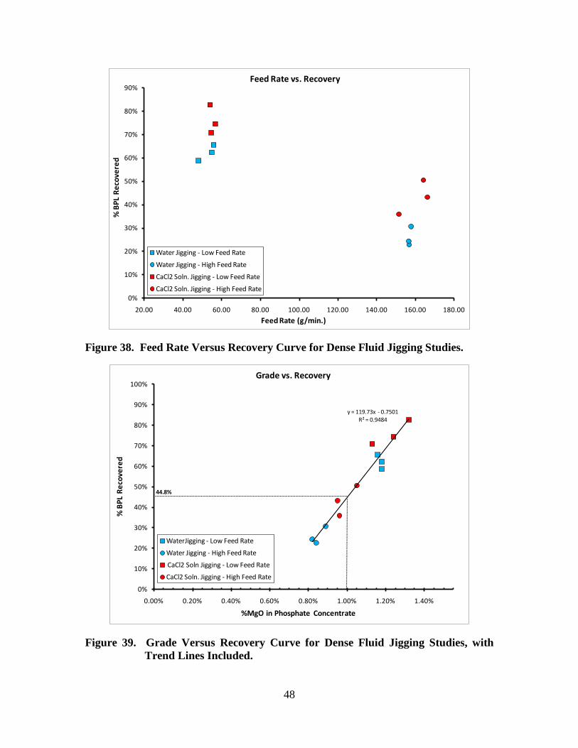
48
0%
10%
20%
30%
40%
50%
60%
70%
80%
90%
20.00 40.00 60.00 80.00 100.00 120.00 140.00 160.00 180.00
% B
PL R
ecov
ered
Feed Rate (g/min.)
Feed Rate vs. Recovery
Water Jigging - Low Feed Rate
Water Jigging - High Feed Rate
CaCl2 Soln. Jigging - Low Feed Rate
CaCl2 Soln. Jigging - High Feed Rate
Figure 38. Feed Rate Versus Recovery Curve for Dense Fluid Jigging Studies.
y = 119.73x - 0.7501R² = 0.9484
0%
10%
20%
30%
40%
50%
60%
70%
80%
90%
100%
0.00% 0.20% 0.40% 0.60% 0.80% 1.00% 1.20% 1.40%
% B
PL R
ecov
ered
%MgO in Phosphate Concentrate
Grade vs. Recovery
WaterJigging - Low Feed Rate
Water Jigging - High Feed Rate
CaCl2 Soln Jigging - Low Feed Rate
CaCl2 Soln. Jigging - High Feed Rate
44.8%
Figure 39. Grade Versus Recovery Curve for Dense Fluid Jigging Studies, with
Trend Lines Included.

49
0%
10%
20%
30%
40%
50%
60%
70%
80%
90%
100%
20.00 40.00 60.00 80.00 100.00 120.00 140.00 160.00 180.00
% B
PL R
ecov
ered
Feed Rate (g/min.)
Feed Rate vs. Recovery
Water Jigging - Low Feed RateWater Jigging - High Feed RateCaCl2 Soln. Jigging - Low Feed RateCaCl2 Soln. Jigging - High Feed RateAverage (water)Average (CaCl2 soln.)
102.5 156.1
Figure 40. Feed Rate Versus Recovery Curve for Dense Fluid Jigging Study,
Including Average Recoveries at Each Condition. One possible explanation for the increase in recovery when using a CaCl2 solution could be a result of the increased fluid density and viscosity. The increase in fluid density and viscosity of the CaCl2 solution may fluidize the ragging balls more than water, resulting in an increase in void space, making it easier for particles to pass through into the hutch.

51
CONTACT ANGLE AND FLOTATION EXPERIMENTS It was determined from jigging experiments that the jigging process could, to some extent, separate the denser dark apatite particles from the dolomite particles. However, characterization showed that a significant portion of the phosphate ore is approximately the same density as the dolomite pebbles. A jigging/flotation process was proposed as a possible method for separating the lighter apatite pebbles from the dolomite pebbles in a scavenger stage. In a jigging/flotation process, air bubbles would selectively attach to the dolomite pebbles, decreasing the apparent density of dolomite and increasing the separation efficiency. The first step in determining the feasibility of a jigging/flotation process was to examine possible dolomite flotation reagents using contact angle measurements. Contact angle experiments were designed keeping in mind that the jigging process would use coarse pebbles (up to 6 mesh). CONTACT ANGLE EXPERIMENTS
Contact angle measurements provide a quantitative way of measuring the effectiveness of flotation reagents. In this study, contact angle methods were used to investigate the effectiveness of certain dolomite flotation reagents proposed for the removal of dolomite from phosphate ores by means of flotation processes. Contact angle measurements have not previously been carried out for dolomite and apatite. Reagents have always been tested directly in laboratory flotation, and have failed in practice.
Contact angle measurements are needed to unambiguously quantify the effects of reagents on the dolomite and apatite surfaces. The dolomite flotation reagents used in this study are proprietary, but are referred to as ‘modified oleic acid’ by the manufacturer. Key flotation parameters such as reagent concentration and pH were varied within the optimum boundaries provided by the manufacturer. Contact Angle Experimental Procedures The procedures are broken down into the following steps: (1) sample preparation, (2) reagent solution preparation, (3) sample conditioning, and (4) contact angle measurement. Each step is discussed in detail below. Sample Preparation Samples used for this investigation were pebbles of approximately 7 mm taken from high-dolomite phosphate ore supplied by Mosaic. Five light yellow-colored pebbles (dolomite) and 5 dark-colored pebbles (apatite) were selected from the phosphate ore. Each pebble was ground flat on two sides to create a “slice,” as shown in Figure 41. This

52
produced a clean, flat surface for contact angle measurements. Pebbles were then set aside until conditioning.
Figure 41. Dolomite (left) and Apatite (right) Pebbles After Being Ground into
"Slices." Reagent Solution Preparation The reagents used in this study are called Custofloat and were received from the manufacturer ArrMaz Custom Chemicals Inc. Six different Custofloat reagents labeled MT1, MT2, MT3, MT4, MT5, and MT6 were tested. The Custofloat manufacturer also provided information on what concentrations and pH levels should be used. It was recommended by the manufacturer that the reagent dosage should be in the range of 0.5-2 kg/ton of feed. It was also indicated that the pH should be slightly acidic (4.5-6).
Reagent solutions were created by adding the appropriate amounts of Custofloat reagent to 400 ml of slightly acidic distilled water (pH 4.5-6). A basis of 70% solids was used to determine the corresponding amount of reagent in solution to add to the 400 ml of slightly acidic distilled water. Using this basis, it was determined that 2,000 μl of reagent would be added for the 2 kg/ton dosage and 500 μl would be added for the 0.5 kg/ton dosage. Reagent solutions were then mixed thoroughly using a stirring rod. Sample Conditioning Samples were conditioned by submerging each pebble in the reagent solution. The solution was then lightly agitated. Three minute conditioning times were used for this study. After 3 minutes the pebbles were removed and placed in plastic weighing dishes. After the contact angle measurements were completed, each pebble was either washed in an acid solution or re-polished to expose new surfaces for the next round of tests.
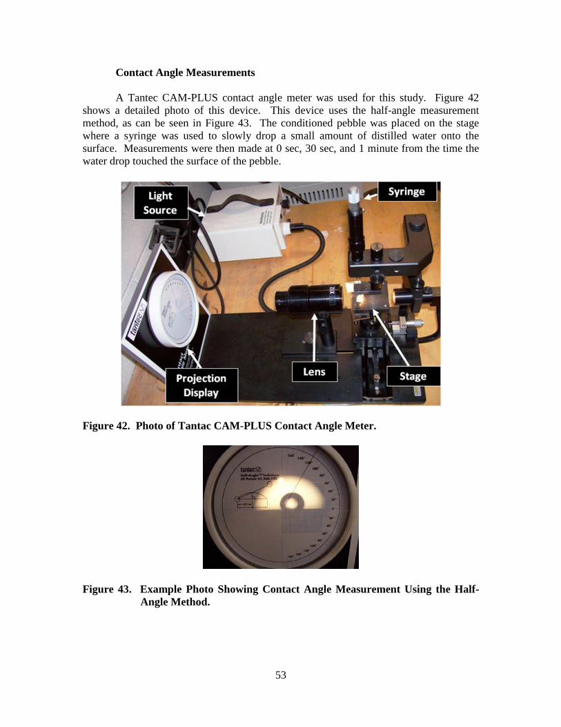
53
Contact Angle Measurements A Tantec CAM-PLUS contact angle meter was used for this study. Figure 42 shows a detailed photo of this device. This device uses the half-angle measurement method, as can be seen in Figure 43. The conditioned pebble was placed on the stage where a syringe was used to slowly drop a small amount of distilled water onto the surface. Measurements were then made at 0 sec, 30 sec, and 1 minute from the time the water drop touched the surface of the pebble.
Figure 42. Photo of Tantac CAM-PLUS Contact Angle Meter.
Figure 43. Example Photo Showing Contact Angle Measurement Using the Half-
Angle Method.

54
Results and Discussion for Contact Angle Experiments
The two key parameters studied were reagent dosage and solution pH. As mentioned in the above sections, the reagent manufacturer described the optimal dosage as 0.5-2 kg/ton at a pH of 4.5-6. Table 16 shows the results for a dosage of 0.5 kg/ton at a pH of 4.5. It was determined that reagents MT2, MT3, and MT6 gave the best results and therefore were selected for further testing. Also, it was noticed that there were a significant number of instances where the contact angle measurement was zero. In many of these cases there was a thin water film on the pebble that simply absorbed the water droplet, leading to contact angle measurements of zero degrees. It was decided that the pebbles would be allowed a certain amount of drying time between the conditioning and contact angle measurements in attempt to achieve measureable contact angles. Table 16. Contact Angle Measurements at a Reagent Dosage of 0.5 kg/ton at a pH
of 4.5.
Dosage: 0.5 kg/ton pH: 4.5 Contact Angle Measurement (Degrees @ 0 Sec, 30 Sec, 1 Min)
Sample Pebble Type MT1 MT2 MT3 MT4 MT5 MT6 1 Dolomite 40,28,26 40,38,34 84,80,76 60,48,34 40,0,0 40,30,28 2 Dolomite 0 0 0 0 0 0 3 Dolomite 0 0 0 0 0 0 4 Dolomite 0 50,50,50 58,56,52 30,20,18 40,0,0 42,34,28 5 Dolomite 0 0 0 0 0 0 6 Apatite 0 0 0 0 0 0 7 Apatite 0 56,38,16 56,52,46 0 0 0 8 Apatite 0 44,38,24 50,40,36 0 0 0 9 Apatite 0 48,30,24 54,54,48 0 0 38,32,26
10 Apatite 0 24,20,18 48,40,38 0 0 0 Table 17. Contact Angle Measurements at a Reagent Dosage of 2 kg/ton at pH of
4.5.
Dosage: 2 kg/ton pH: 4.5 Contact Angle Measurement (Degrees @ 0 Sec, 30 Sec, 1 Min)
Sample Pebble Type MT2 MT3 MT6* 1 Dolomite 0 68,52,46 50,40,38 2 Dolomite 0 0 64,20,10 3 Dolomite 0 0 64,50,48 4 Dolomite 42,36,30 50,48,48 50,16,10 5 Dolomite 0 64,46,42 66,56,48 6 Apatite 0 0 24,12,12 7 Apatite 0 50,34,30 64,18,10 8 Apatite 0 70,40,36 40,20,10 9 Apatite 0 64,42,36 48,38,34
10 Apatite 0 52,34,34 38,26,20 * Allowed to air dry for 24 hours before making contact angle measurements.

55
Table 17 gives results for trials at a dosage of 2 kg/ton and pH of 4.5. It should be noted that for the MT6 trial, the pebbles were allowed to dry for 24 hours. Results showed that allowing a drying time increased the initial contact measurement at 0 seconds. However, in most instances where the contact angle measurement had previously been 0, a rapid decay in contact angle was observed. After this trial, the procedures were modified to allow for 5 minutes of drying time between pebble conditioning and contact angle measurements.
Table 18 gives the results for trials conducted at a dosage of 0.5 kg/ton and pH of 4.5. Pebbles were allowed to dry for 5 minutes after being conditioned. It should also be noted that for this trial the reagent solution was created by adding 125μl of Custofloat reagent to 100ml of slightly acidic distilled water. This change was made in attempt to increase contact between the pebbles and reagent during the conditioning step in cases where the reagents produced emulsions instead of dissolving into solution. Results showed an increase in contact angle measurements for MT2. However, contact angles were still significantly lower than what is needed for flotation, and no significant selectivity was observed. Table 18. Contact Angle Measurements at a Reagent Dosage of 0.5 kg/ton at pH of
4.5. Dosage: 0.5 kg/ton*
pH: 4.5 Contact Angle Measurement (Degrees @ 0 Sec, 30 Sec, 1 Min)
Sample Pebble Type MT2 MT3 MT6
1 Dolomite 46,34,26 48,44,44 44,26,22 2 Dolomite 18,0,0 0 60,32,28 3 Dolomite 48,30,16 54,28,14 56,34,28 4 Dolomite 60,36,26 58,44,34 0 5 Dolomite 48,38,22 66,50,44 52,36,24 6 Apatite 20,0,0 32,0,0 0 7 Apatite 20,0,0 58,36,34 0 8 Apatite 36,18,16 54,44,38 38,24,20 9 Apatite 54,28,24 59,44,34 50,38,34
10 Apatite 34,24,18 50,34,28 32,20,16 *Solution was created by adding 125 μl of Custofloat reagent to 100 ml of slightly acidic distilled water. Conclusions from Contact Angle Experiments
Initial contact angle testing procedures resulted in many zero degree measurements. These contact angle procedures went through numerous modifications to ensure accurate contact angle measurements were made. Unfortunately, results continually showed very low contact angles, with no discernible difference in contact angles between dolomite and apatite pebbles. Based on these contact angle measurements and methods, the reagents are not sufficient for flotation separation of

56
dolomite from apatite. For effective reagents, we would expect contact angles >90o for the floating species, and at least a 20o difference between floating and non-floating species. FLOTATION EXPERIMENTS Results from the contact angle experiments showed that the Custofloat reagents were not conducive to the removal of dolomite from phosphate ores via flotation processes. However, with some questions regarding the contact angle procedures, a more conventional approach was taken to determine the effectiveness of Custofloat reagents. Denver float cells were used to perform batch flotation experiments, which would provide another method for measuring reagent effectiveness and comparing it with the contact angle results.
Flotation Experiment Procedures Procedures for the batch-scale dolomite flotation experiments are shown below in Figure 44. First, a high-MgO feed ore was sized to -32/+150 mesh. The feed ore was then washed 10 times with distilled water to remove ultrafine clays. Next, the Custofloat reagent was added at a dosage of 2 kg/ton. Slightly acidic tap water (adjusted with H2SO4 to pH 5.5-6) was added until a 70% solids slurry was achieved. The slurry was then mixed for 5 minutes using a mechanical mixer.
Next, the conditioned slurry was transferred to a laboratory-scale Denver float cell. The mixer was lowered into the cell, turned on, and flotation was carried out for 10 minutes. The flotation froth was continually scraped off into a tailings collection pan. More slightly acidic tap water was periodically added to the cell as make-up water. Finally, the phosphate concentrate (sinks) and dolomite-rich rejects (floats) were filtered, dried, and prepared for analysis. These procedures were followed for 6 different experiments in which the only variable changed was the flotation reagent. Custofloat reagents MT1, MT2, MT3, MT4, MT5, and MT6 were tested and the results are shown in Table 19.

57
Figure 44. Procedures Used for Dolomite Flotation Experiments. Table 19. Results from Dolomite Flotation Experiments. Test No. Collector Sample % MgO % BPL % Feed
MgO % Weight
Recov. % BPL Recov.
% MgO Recov.
1 MT1 Dolomite tailings 3.99 53.30 1.41 18.97 20.25 53.61 Phosphate conc. 0.81 49.12 81.03 79.75 46.39
2 MT2 Dolomite tailings 2.39 60.97 1.59 36.81 45.01 55.36 Phosphate conc. 1.12 43.38 63.19 54.99 44.64
3 MT3 Dolomite tailings 5.13 52.34 1.64 8.81 9.18 27.58 Phosphate conc. 1.30 49.97 91.19 90.82 72.42
4 MT4 Dolomite tailings 2.13 53.68 1.56 52.80 56.35 72.05 Phosphate conc. 0.92 46.52 47.20 43.65 27.95
5 MT5 Dolomite tailings 4.08 53.30 1.57 19.59 20.77 50.78 Phosphate conc. 0.96 49.52 80.41% 79.23 49.22
6 MT6 Dolomite tailings 5.45 48.78 1.50 5.43 5.14 19.70 Phosphate conc. 1.28 50.63 94.57 94.86 80.30

58
Table 20. Particle Size Analysis of Concentrate and Tailings from Flotation Experiments.
Collector 80% Passing Size (µm) Concentrate Tailings
MT1 360 11 MT2 383 173 MT3 360 13 MT4 410 200 MT5 359 13 MT6 325 15
While these experiments did show selectivity between dolomite and phosphate, the results are somewhat deceptive. Examination of the products showed that the flotation experiments that generated the highest-dolomite froth products were primarily recovering the finest particles into the froth (see Table 20). Since dolomite particles are more easily broken and abraded than the phosphate particles, the finest size fraction of the ore tends to become enriched in dolomite as it is handled and processed. The apparent separation by froth flotation was therefore largely due to classification by size, with the dolomite-enriched fines being preferentially floated. This suggests that similar results could have been more easily achieved through screening or hydraulic classification.

59
COST ESTIMATION ANALYSIS One of major benefits of jigs is that they are generally considered to be significantly cheaper than most other separation processes. The well-known book Mining and Mineral Processing Equipment Costs and Preliminary Capital Cost Estimations, by A.L. Mular (1982), was used to estimate equipment costs for the jigging process. Processing costs for heavy media separation and flotation were also calculated for comparison. In the following sections, costing procedures and calculations for each process are shown. COST ESTIMATION PROCEDURES AND CALCULATIONS General Cost Estimation Procedure The general procedure for equipment cost estimation is described below in a step-by-step procedure. Step (1) Assume a basis; choose the proper equipment size. A basis needed to be assumed in order to compare each separation process with each other. For this cost estimation analysis, a feed rate of 100 tph was used as a basis. After choosing the basis, the given parameters for each process were used to determine proper equipment size. Step (2) Determine what equipment is included in the cost equation, and what equipment must be added. For each separation process there is a list of the equipment that is included/excluded from the given cost equation. For the excluded, or “extra” items, further costing needed to be done. The costs of the extras were also determined using Mular’s book on equipment cost estimation.
• Jigs • Included – cost of jig and motor • Extras – ragging and hutch water pump
• Heavy Media Separator • Included – heavy media drum or cone separator, screen densifier,
magnetic separator, pumps, hoppers, sumps, launders and motor controls • Extras – none
• Flotation Cells • Included – flotation cells, motor guard, feed/discharge boxes • Extras – motors, launders, and paddles

60
Step (3) Determine costs for each process. Estimate the cost of each process involved following the procedures described in Mular’s book on equipment costs estimation. Since each process involved slightly different costing procedures, details for each separation process are given in the following sections. Step (4) Converting from 1982 Canadian $ to Current U.S. $. In Mular’s book, costs are determined in 1982 Canadian dollars (when the book was written). Therefore, conversions were needed to determine the costs in current U.S. dollars.
• In 1982, the exchange rate was $1.19 Canadian for $1 U.S. dollar.
( ) $1 US$US = $Canadian$1.19Canadian
x
(3)
Step (5) Converting from 1982 U.S. $ to 2011 U.S. $. After converting to 1982 U.S. dollars, the next step was to convert to 2011 U.S. dollars. In Mular’s book, all prices were given at a Marshall & Swift (mining and milling) cost index equal to 800. Equation 2 is used to convert 1982 dollars to 2011 dollars. The Marshall & Swift (mining and milling) cost index for 2011(Q1) was 1599.7.
cost index nowCost now =(cost then)cost index then
(4)
Step (6) Calculating delivered and installed costs. Since the cost estimation only gives the equipment costs, other factors such as delivery and installation must be taken into consideration. To estimate the delivered cost of an item, its equipment cost was multiplied by 1.03. To estimate the installed cost, delivered cost was multiplied by 1.39. Delivered cost = (1.03) × (equipment cost) .............................................. (5) Installed cost = (1.39) × (delivered cost) .................................................. (6) Cost Estimation of Jigging Process A step-by-step process for estimating the cost of the jigging process is described below. The total estimated cost of the jigging process (with extras) was $50.1 K U.S. (2011).

61
Cost Estimation of Jig (1) Basis: feed rate of 100 tph; choose the proper equipment size
• Choose a jig that can handle 100 tph feed • Duplex style jig • 12”×18” jigging area (216 in2)
(2) Determine what equipment is included in the cost equation, and what
equipment must be added. • Jigs
• Includes cost of jig and motor • Extras: ragging and hutch water pump
(3) Use cost equation with correct parameters
Cost=(a)(Xb) • where a and b are parameters, and X is jigging area in inches2
• For a duplex jig size of 216 in2, use parameters a=4930; b=0.1786, as shown in Table 21.
• Cost=(4930)(X0.1786) = $12,875.98 Canadian (1982) (4) Convert to 1982 U.S. dollars
• $ U.S. (1982) = ($12,875.98 CDN) × ($1US / $1.19 CDN) = $10,820.15 U.S.
(5) Convert to 2011 U.S. dollars
• Cost now = ($10,820.15) × (1599.7 / 800) = $21,636.25 (6) Delivered and installed cost
• Delivered cost = (1.03) × ($21,636.25) = $22,285.34 U.S. (2011) • Installed cost = (1.39) × ($22,258.34) = $30,976.62 U.S. (2011)
Table 21. Jig Cost Estimation Parameters (Mular 1982).
Jig Type Jig Size Range (Sq. In.)
Parameters (a) (b)
Simplex 24 to 217.22 6498.7 0.05716 217.22 to 864 742.7 0.4603
Duplex 96 to 233.16 4930 0.1786 233.16 to 864 1069.8 0.4589
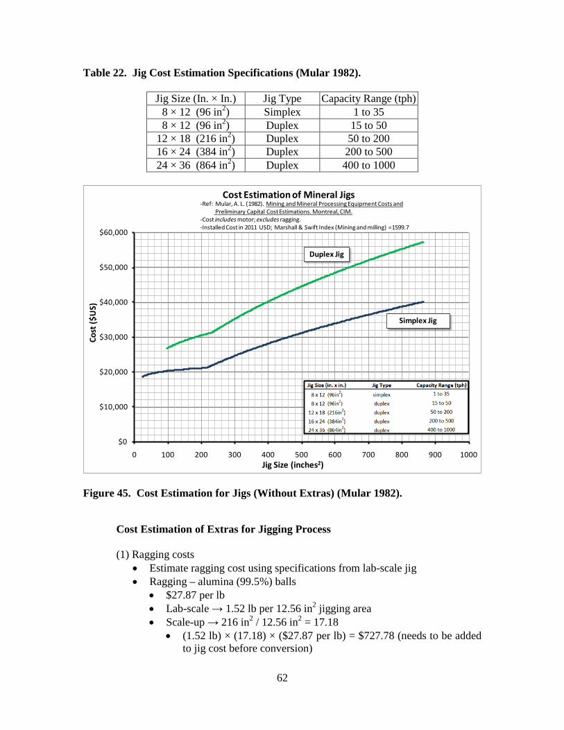
62
Table 22. Jig Cost Estimation Specifications (Mular 1982).
Jig Size (In. × In.) Jig Type Capacity Range (tph) 8 × 12 (96 in2) Simplex 1 to 35 8 × 12 (96 in2) Duplex 15 to 50
12 × 18 (216 in2) Duplex 50 to 200 16 × 24 (384 in2) Duplex 200 to 500 24 × 36 (864 in2) Duplex 400 to 1000
$0
$10,000
$20,000
$30,000
$40,000
$50,000
$60,000
0 100 200 300 400 500 600 700 800 900 1000
Cost
($U
S)
Jig Size (inches2)
Cost Estimation of Mineral Jigs
Duplex Jig
Simplex Jig
-Ref: Mular, A. L. (1982). Mining and Mineral Processing Equipment Costs and Preliminary Capital Cost Estimations. Montreal, CIM.
-Cost includes motor; excludes ragging.-Installed Cost in 2011 USD; Marshall & Swift Index (Mining and milling) =1599.7
Figure 45. Cost Estimation for Jigs (Without Extras) (Mular 1982). Cost Estimation of Extras for Jigging Process (1) Ragging costs
• Estimate ragging cost using specifications from lab-scale jig • Ragging – alumina (99.5%) balls
• $27.87 per lb • Lab-scale → 1.52 lb per 12.56 in2 jigging area • Scale-up → 216 in2 / 12.56 in2 = 17.18
• (1.52 lb) × (17.18) × ($27.87 per lb) = $727.78 (needs to be added to jig cost before conversion)

63
(2) Hutch water pump • Includes drive; motor is extra • Based on lab-scale jig → 0.5 gpm per 12.56 in2 • Scale-up → 0.5 gpm × (17.18) = 8.59 gpm • Cost using single-stage centrifugal pump
• Cost = 2883.9 × (50)0.1613 = $5,420.31 • Motor cost (TEFC motor 575V)
• Cost = 227.40 × (10)0.9022 = $1,815.48 • Total cost = $5,420.31 + $1,815.48 = $7,235.76 (needs to be added to jig
cost before conversion) (3) Total costs of extras (1982 $CDN)
• Total costs of extras = $727.78 + $7,235.76 = $7,963.54 (CDN 1982) (4) Convert to 1982 U.S. dollars
• $ U.S. (1982) = ($7,963.54 CDN) × ($1 U.S. / $1.19 CDN) = $6,692.05 U.S.
(5) Convert to 2011 U.S. dollars
• Cost now = ($6,692.05) × (1599.7 / 800) = $13,381.59 U.S. (2011) (6) Delivered and installed cost
• Delivered cost = (1.03) × ($13,381.59) = $13,783.04 U.S. (2011) • Installed cost = (1.39) × ($13,783.04) = $19,158.42 U.S. (2011)
Total Estimated Cost of Jigging Process In order to get the total estimated costs of the jigging process, the cost of the jig ($30,976.62) is added to the extra costs ($19,158.42) to give a total estimated cost of $50,135.04 U.S. (2011). Cost Estimation for Heavy Media Separation Process A step-by-step process for estimating the cost of the heavy media separation process is described below. The total estimated cost of the heavy media separation process (with extras) was $1,031 K U.S. (2011). (1) Basis: feed rate of 100 tph; choose the proper equipment size
• Choose a heavy media separator that can handle 100 tph feed • 8 × 8 ft drum; or 10 ft dia. cone → capacity range (40-140 tph)
(2) Determine what equipment is included in the cost equation, and what
equipment must be added. • Heavy Media Separator

64
• Includes heavy media drum or cone separator, screen densifier, magnetic separator, pumps, hoppers, sumps, launders and motor controls
• Extras: none (2) Use cost equation with correct parameters
Cost=(a)(Xb) • where a and b are parameters, and X is capacity in tph
• For a HMS with a capacity of 100tph use parameters a=148637; b=0.230 as shown in table 23.
• Cost=(148637)(X0.230) = $428,673.79 Canadian (1982) (3) Convert to 1982 U.S. dollars
• $ U.S. (1982) = ($428,673.79 CDN) × ($1 U.S. / $1.19CDN) = $360,230.08 U.S.
(4) Convert to 2011 U.S. dollars
• Cost now = ($360,230.08) × (1599.7 / 800) = $720,325.07 U.S. (2011) (5) Delivered and installed cost
• Delivered cost = (1.03) × ($720,325.07) = $741,934.82 U.S. (2011) • Installed cost = (1.39) × ($741,934.82) = $1,031,289.40 U.S. (2011)
Table 23. Cost Estimation Parameters and Specifications for Heavy Media
Separation Process (Mular 1982).
Heavy Media Separator Range (tph) Parameters (a) (b)
15 to 200 148,637 0.230 Drum (Dia. × Length) Cone Dia. (ft) Capacity Range (tph) 4 ft. × 4 ft. 5 5 to 20 6 ft. × 6 ft. 7 20 to 70 8 ft. × 8 ft. 10 40 to 140 10 ft. × 10 ft. 14 80 to 250

65
$500,000
$600,000
$700,000
$800,000
$900,000
$1,000,000
$1,100,000
$1,200,000
$1,300,000
$1,400,000
0 50 100 150 200 250 300
Cost
($U
S)
HMS Capacity (tph)
Cost Estimation of Heavy Media Separator Assembly
Heavy Media Separator
-Ref: Mular, A. L. (1982). Mining and Mineral Processing Equipment Costs and Preliminary Capital Cost Estimations. Montreal, CIM.
-Cost includes heavy media drum or cone separator, screen densifier, magnetic separator, pumps, hoppers, sumps, launders and motor controls-Cost in 2011 USD; Marshall & Swift Index (Mining and milling) = 1599.7
Figure 46. Cost Estimation for Heavy Media Separation (Mular 1982). Cost Estimation for Flotation Process The total estimated cost of the flotation process (with extras) was $322.3 K U.S. (2011). A step-by-step process for estimating the cost of the flotation process is described in the next section. Cost Estimation for Flotation Cells (1) Basis: feed rate of 100 tph; choose the proper equipment size
• Choose a flotation cell that can handle 100 tph feed • Using the coal throughput estimations for a 300 ft3 cell → capacity
350 tons per day → 14.5 tph • So, 100 tph / 14.5 tph = 6.9 cells needed → round up to 7 cells
(2) Determine what equipment is included in the cost equation, and what
equipment must be added. • Flotation Cells
• Includes flotation cells, motor guard, feed/discharge boxes • Extras: launders, motors, and paddles

66
(3) Use cost equation with correct parameters Cost=(a)(Xb)
• where a and b are parameters, and X is cell size in ft3 • For a flotation cell size of 300 ft3 use parameters a=482.4; b=0.6121,
as shown below in Table 24. • Cost = (482.4)(X0.6121) = $15,863.28 Canadian (1982)
• $15,863.28 per cell × (7 cells) = $110,853.97 Canadian (1982) Table 24. Flotation Cell Cost Estimation Parameters and Specifications (Mular
1982).
Flotation Cells
Range (Ft3)
Parameters (a) (b)
3 to 99.58 1,955.3 0.3079 99.58 to 1275 482.4 0.6121
Cell Vol. (Ft3)
Tons Per Day Per Cell Motor HP Per Cell Cu Fe Zn Pb Coal
25 25-40 30-40 20-30 25-40 20-25 7.5 40 50-80 60-80 40-60 50-80 40-50 10 50 80-120 100-120 50-85 80-120 60-70 15 100 130-200 165-200 85-140 130-200 100-115 25 180 200-300 250-310 125-210 200-300 150-175 40 300 400-600 500-600 250-425 400-600 300-350 50 500 -- -- -- -- -- 80 1275 -- -- -- -- -- 150

67
$0
$10,000
$20,000
$30,000
$40,000
$50,000
$60,000
$70,000
$80,000
$90,000
$100,000
0 200 400 600 800 1000 1200 1400
Cost
($ U
S)
Cell Volume (ft3)
Cost Estimation of Flotation Cells
Flotation
-Ref: Mular, A. L. (1982). Mining and Mineral Processing Equipment Costs and Preliminary Capital Cost Estimations. Montreal, CIM.
-Cost includes motor guard, feed/discharge boxes; excludes motors, launders, blowers, and paddles-Cost in 2011 USD; Marshall & Swift Index (Mining and milling) = 1599.7
Figure 47. Cost Estimation of Flotation Cells (Without Extras) (Mular 1982). Cost Estimation of Extras for the Flotation Process
• Launders • App. $100 per ft of cell lengths • From Metso DR-300 flotation cell data sheet
• (7.33 ft/cell) × 7 cells = 51.3 ft • Total cost of launders = 51.3 ft × $100/ft = $5,133 Canadian (1982)
• Motors (drip-proof motors, 575V, pg. 170)
• Need 30 hp of each cell (based on Metso DR-300 float cell spec sheet) Cost=(a)(Xb)
• where a and b are parameters, and X is hp • For a drip proof motor (575V) with 30 hp, use parameters a=34.07;
b=1.0340 • Cost = (34.07)(X1.0340) = $1,147.23 Canadian (1982)
• Total cost of motors = $1,147.23 per cell × (7 cells) = $8,030.63 Canadian (1982)
• Paddles
• ≈9% of cost per cell

68
• Cost = 0.09 × $15,836.28 = $1,425.27 per cell • Total cost of paddles = $1,425.27 / cell × 7 cells = $9,977 Canadian
(1982) Total Estimated Cost of Flotation (1) Total estimated cost Canadian (1982) = $110,853.97 + $5,133 + $8,031 +
$9,977 = $133,994.80 Canadian (1982) • $ U.S. (1982) = ($133,994.80 CDN) × ($1 U.S. / $1.19 CDN) =
$112,600.67 U.S. (1982) (2) Convert to 2011 U.S. dollars
• Cost now = ($112,600.67) × (1599.7 / 800) = $225,159.11 U.S. (2011) (3) Delivered and installed cost
• Delivered cost = (1.03) × ($225,159.11) = $231,913.89 U.S. (2011) • Installed cost = (1.39) × ($231,913.89) = $322,360.30 U.S. (2011)
COST ESTIMATE SUMMARY The installed cost of a fully-equipped jig with a capacity of 100 tons per hour is estimated at $50,135. In comparison, using the same cost estimation procedures the installed cost of a 100 ton per hour heavy media plant would be $1,031,289, which is approximately 20 times more than the cost of the jig plant. It is therefore clear that, all other things being equal, the jig is a far more economical choice for dolomite removal from phosphate pebble. A 100 ton per hour froth flotation plant for dolomite removal, at a cost of $322,360, would still be 6.4 times more expensive than a jig plant of comparable capacity. The froth flotation plant would have the added problem that, to date, there are no flotation reagents that can reliably remove enough of the dolomite to make the process viable. Therefore, based both on the dramatically lower costs, and on the proven ability of the jig to reject a large fraction of the dolomite from phosphate, it is clear that jigging is a much more viable approach than these alternatives.

69
CONCLUSIONS Jigging was investigated as a method for the removal of dolomite from high-MgO phosphate ore. First, experiments were designed to optimize jigging performance. Second, tests were run with different phosphate ores (crushed and uncrushed) to determine how the jig performed with different feeds. Third, a dense fluid (CaCl2 solution) was tested as a method for improving jigging efficiency. Finally, contact angle measurements were completed as part of an experiment to determine the feasibility of a jigging/flotation process. Conclusions from these studies are listed below.
• It was found using a batch-scale testing procedure that 200 pulses/minute was the optimal pulsation frequency for this application.
• The optimal stroke length at the given operating conditions was determined to
be 1 inch. It was also found that stroke length had a greater effect on the separation than hutch water flow rate at the tested parameter levels.
• Varying ragging densities gave no noticeable advantages or disadvantages for
this separation. However, alumina balls were found to be best suited for current testing procedures as they are highly durable and corrosion resistant. Future jigging tests using a less dense ragging may be useful.
• The jig was found to perform reasonably well with different high-MgO
phosphate feeds. It is possible that crushed high-MgO phosphate feeds performed better due to fine high-MgO particles reporting to the tailings.
• With the dolomite pebbles provided for testing by Mosaic, it was found that
MgO levels could be reduced to below 1% while still recovering approximately 50% of the pebble weight. This shows that the jig process is capable of making the desired specification.
• Experiments with hand-sorting of particles showed that the jig approaches the
minimum achievable levels of MgO for a given phosphate rock sample. When the individual phosphate pebbles have a low level of contained MgO, then the jig can produce a similarly low-MgO product by removing the discrete MgO-bearing pebbles.
• It was initially observed that jigging with a dense fluid increased the recovery
(or throughput). Experiments using both water and a dense jigging fluid, with the same feed ore, were completed to confirm this observation. Based on results, it can be predicted that the throughput can be increased by approximately 52.3% when using a dense jigging fluid and a given phosphate feed ore. It is believed that the increase in throughput could be due to greater fluidization of the ragging material by the denser and more viscous CaCl2 solution.

70
• With our testing procedures, contact angle measurements showed that the proposed reagents were not capable of achieving the required selectively hydrophobic surface on the dolomite pebbles needed for a coarse particle jigging/flotation process. Further investigation of flotation reagents could include contact angle measurements using the captive bubble technique with different conditioning processes.
• Cost estimation calculations indicate that a jig installation would cost
approximately 1/20th as much as a heavy-media plant of the same capacity. Froth flotation is not yet a viable alternative due to poor selectivity for dolomite, but even if an appropriate froth flotation reagent could be developed for removing dolomite, a jig installation would still be approximately 1/6th the cost of the flotation circuit.

71
REFERENCES Barton CJ. 1948. Photometric analysis of phosphate rock. Analytical Chemistry 20(11): 1068-73. Duval C. 1963. Inorganic thermogravimetric analysis. New York: American Elsevier Publishing Company. p 221. El-Shall H, Zhang P, Snow R. 1996. Comparative analysis of dolomite/francolite flotation techniques. Minerals & Metallurgical Processing 13(3): 135-40. Gu Z, Gao Z, Zheng S. 1999. Beneficiation of Florida dolomitic phosphate pebble with a fine-particle flotation process. In: Zhang P, El-Shall H, Wiegel R, editors. Beneficiation of phosphates: advances in research and practice. Littleton (CO): Society for Mining, Metallurgy, and Exploration. p 155-62. Gupta A, Yan DS. 2006. Mineral processing design and operations: an introduction. Amsterdam: Elsevier. p 494-554. Karantzavelos GE, Frangiscos AZ. 1984. Contribution to the modelling of the jigging process. In: Herbst JA. Control 84: mineral metallurgical processing. New York: AIME. p 97-105. Mukherjee AK, Mishra BK. 2006. An integral assessment of the role of critical process parameters on jigging. International Journal of Mineral Processing 81(3): 187-200. Mular AL. 1982. Mining and mineral processing equipment costs and preliminary capital cost estimations. Montreal: CIM. 256 p. Notholt AJG, Sheldon RP, Davidson DF. 1989. Phosphate deposits of the world: Volume 2, Phosphate rock resources. New York: Cambridge University Press. p 62-70. Quinlan KP, DeSesa MA. 1955. Spectrophotometric determination of phosphorus as molybdovanadophosphoric acid. Analytical Chemistry 27(10): 1625-9. Reeves RA. 2002. Types and characteristics of heavy-media separators and flowsheets. In: Mular AL, Halbe DN, Barrat DJ. Mineral processing plant design, practice, and control proceedings. Littleton (CO): Society for Mining, Metallurgy, and Exploration. p 962-94. Somasundaran P, Zhang L. 1999. Role of surface chemistry of phosphate in its beneficiation. In: Zhang P, El-Shall H, Wiegel R, editors. Beneficiation of phosphates: advances in research and practice. Littleton (CO): Society for Mining, Metallurgy, and Exploration. p 141-54.

72
UNIDO, IFDC. 1998. Fertilizer manual. Dordecht: Kluwer Academic Publishers. p 85-126. Zhang P. 1993. Phosphate beneficiation—trends of the 90's. In: El-Shall HE, Moudgil BM, Wiegel RL. Beneficiation of phosphate: theory and practice. Littleton (CO): Society for Mining, Metallurgy, and Exploration. p 399-425.