overview of impedance and phases of rc circuits for ac sources….w/ examples! phy230 –...
TRANSCRIPT

Overview of Impedance and Phases of RC Circuits for AC
Sources….w/ Examples!
PHY230 – ElectronicsProf. Mitchell
What Are We Reviewing???The relationship between current and voltage in an RC circuit
How to determine the impedance and phase angle in a series RC
circuit
How to analyze a series RC circuit
How to determine the impedance and phase angle in a parallel RC
circuit
How to analyze a parallel RC circuit
REMEMBER: i = j sometimes for electrical engineers,
which is where some of these figures are from!

AC Response of a Series RC Circuit
The current through a capacitor leads the voltage across it.
The current must be the same everywhere because it is a series circuit.
Thus, the capacitor voltage lags the source voltage.
Capacitance causes a phase shift between voltage and current that depends on the relative values of the resistance and the capacitive reactance
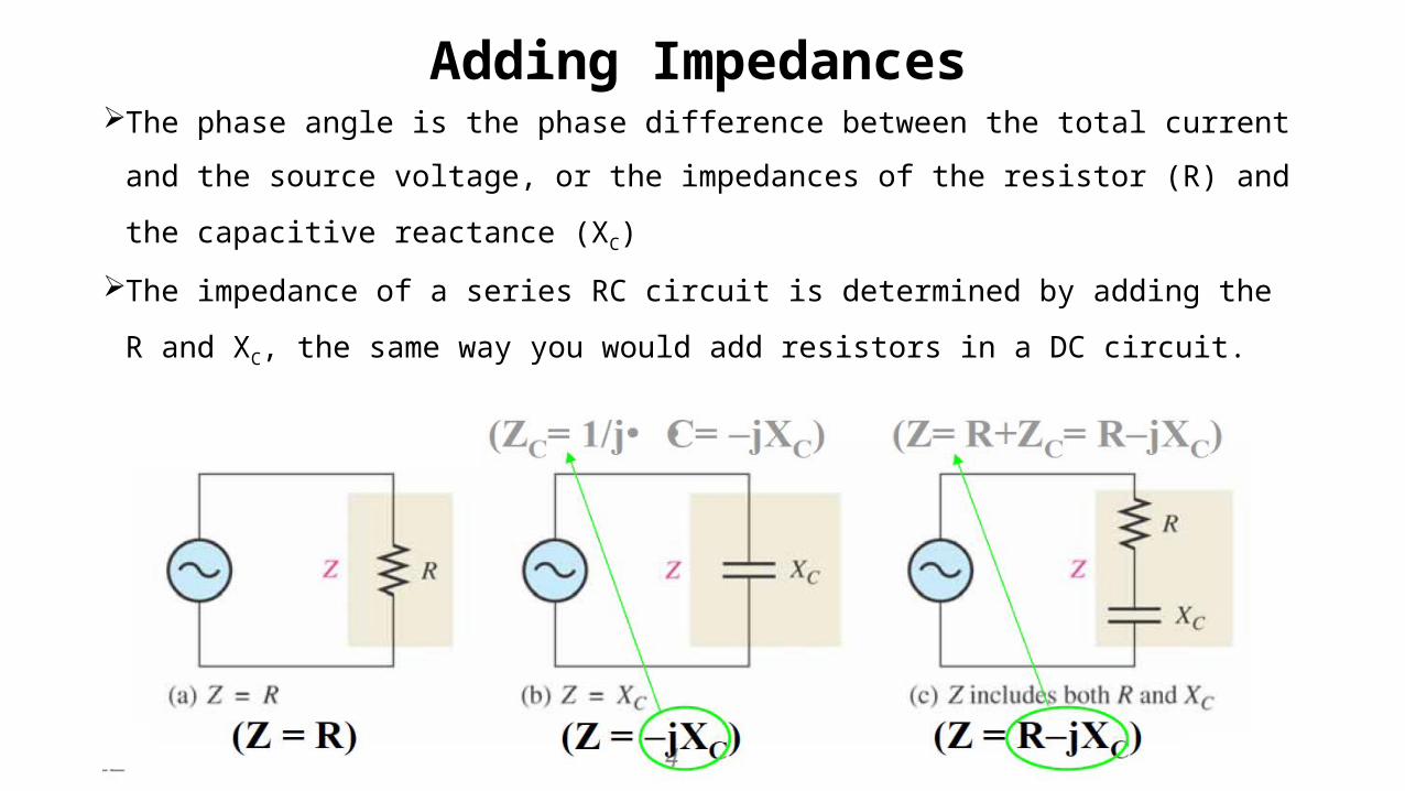
Adding ImpedancesThe phase angle is the phase difference between the total
current and the source voltage, or the impedances of the resistor
(R) and the capacitive reactance (XC)
The impedance of a series RC circuit is determined by adding the
R and XC, the same way you would add resistors in a DC circuit.
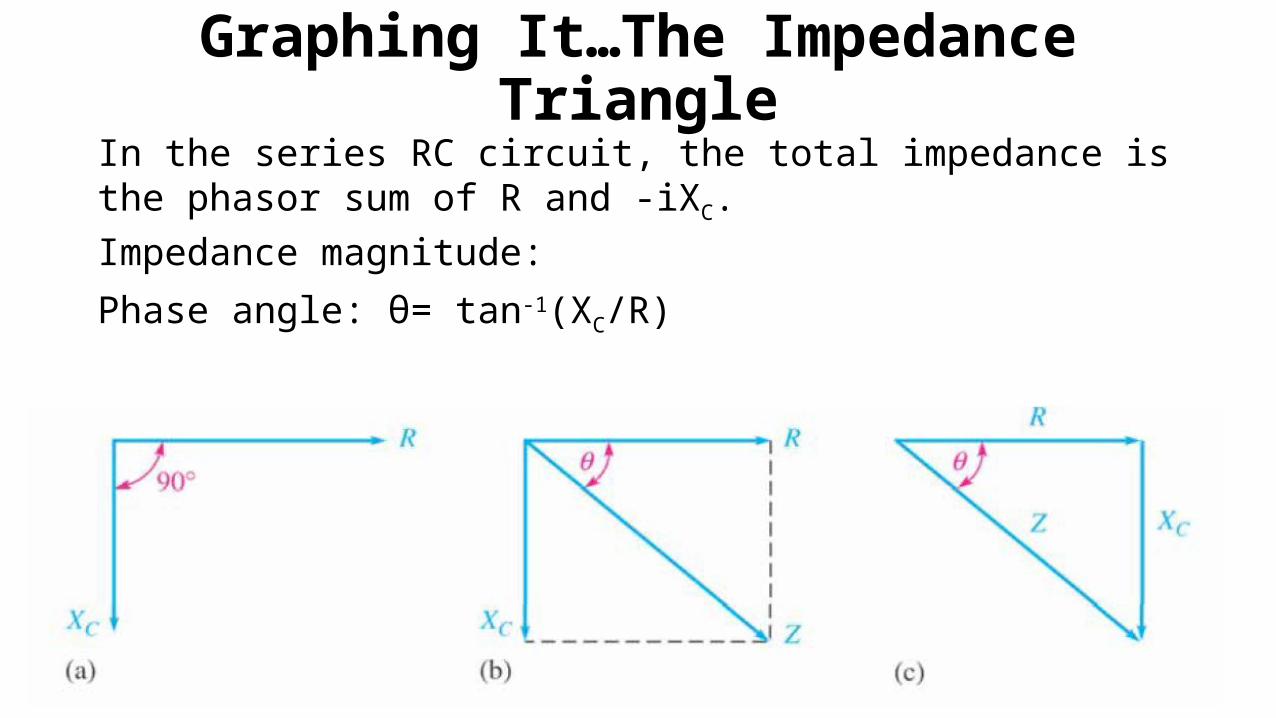
Graphing It…The Impedance Triangle
In the series RC circuit, the total impedance is the phasor sum of R and -iXC.
Impedance magnitude:
Phase angle: θ= tan-1(XC/R)
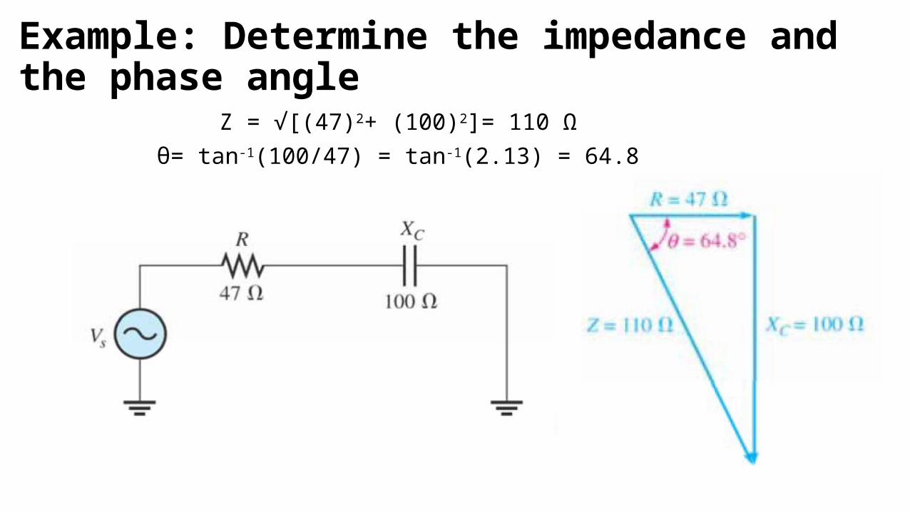
Example: Determine the impedance and the phase angle
Z = √[(47)2+ (100)2]= 110 Ω
θ= tan-1(100/47) = tan-1(2.13) = 64.8
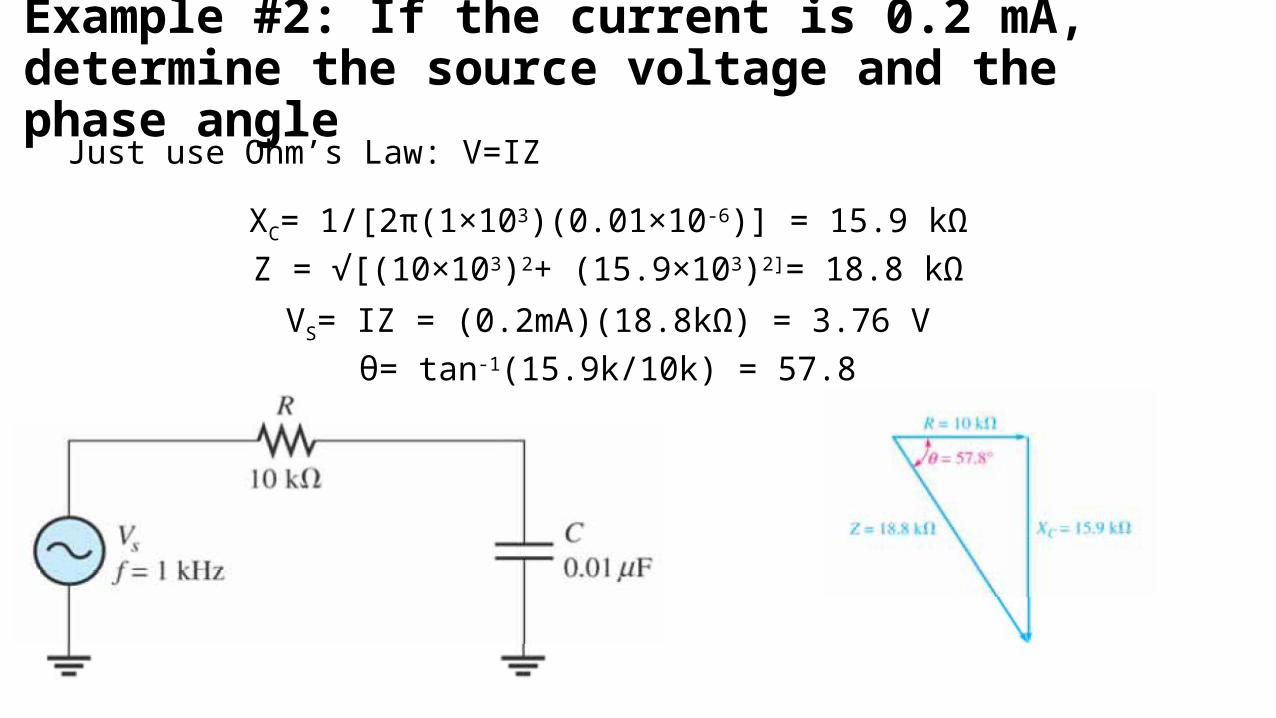
Example #2: If the current is 0.2 mA, determine the source voltage and the phase angle
Just use Ohm’s Law: V=IZ
XC= 1/[2π(1×103)(0.01×10-6)] = 15.9 kΩZ = √[(10×103)2+ (15.9×10³)2]= 18.8 kΩ
VS= IZ = (0.2mA)(18.8kΩ) = 3.76 Vθ= tan-1(15.9k/10k) = 57.8

Current, Voltage and ImpedanceIn a series circuit, the current is the same through both the
resistor and the capacitor.The resistor voltage is in phase with the current, and the
capacitor voltage lags the current by 90.XC and R also follow the voltage so, XC lags R!
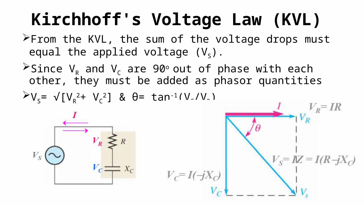
Kirchhoff's Voltage Law (KVL)From the KVL, the sum of the voltage drops must equal
the applied voltage (VS).Since VR and VC are 90o out of phase with each other,
they must be added as phasor quantitiesVS= √[VR
2+ VC2] & θ= tan-1(VC/VR)
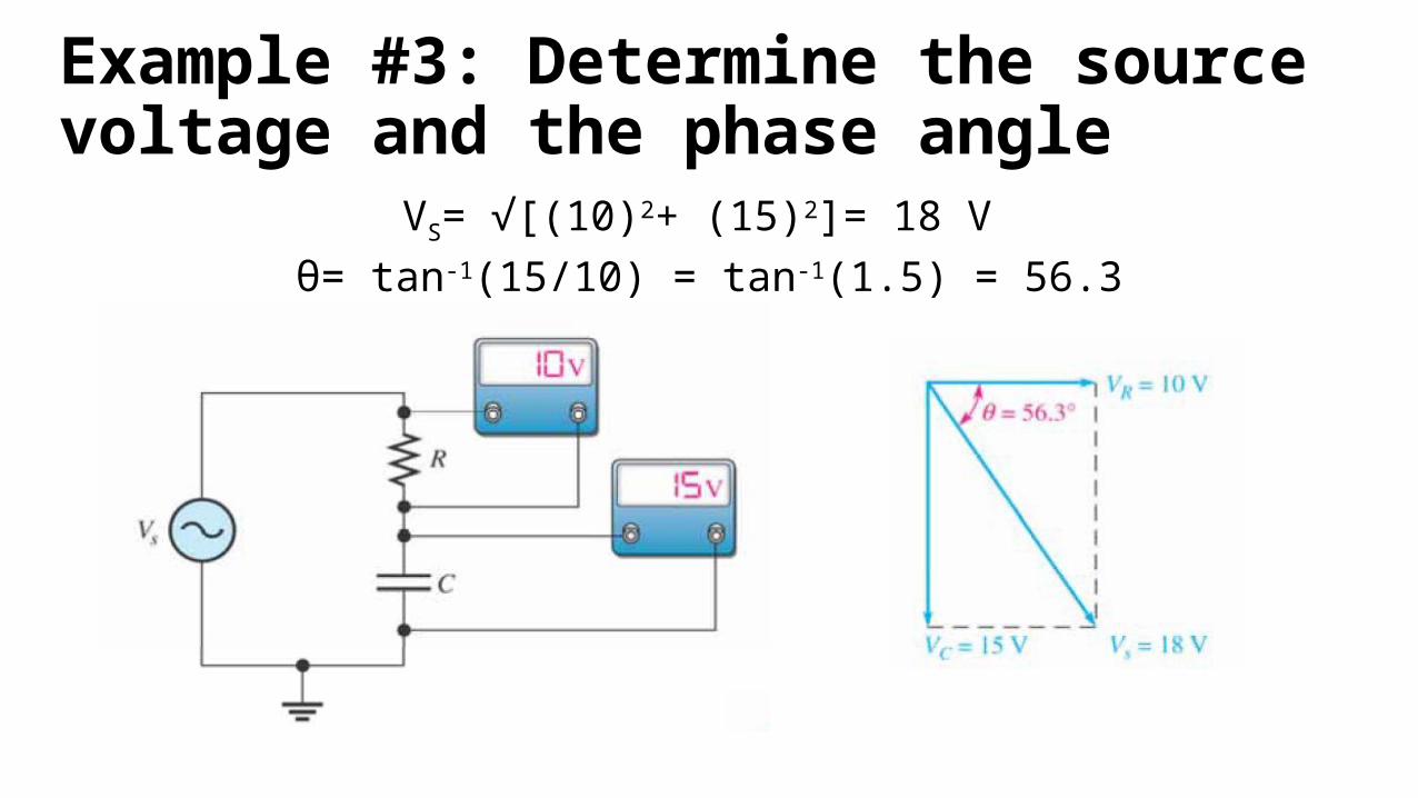
Example #3: Determine the source voltage and the phase angle
VS= √[(10)2+ (15)2]= 18 V
θ= tan-1(15/10) = tan-1(1.5) = 56.3

How Do Things Change With Frequency?
For a series RC circuit, as frequency increases:–R remains constant
–XC decreases
–Z decreases–θ decreases

Example #4: Determine the impedance and phase angle for each of the following values of frequency: (a) 10 kHz (b) 30 kHz
(a) XC= 1/2π(10×103)(0.01×10-6) = 1.59 kΩZ = √[(1.0×10³)2+ (1.59×10³)2]= 1.88 kΩθ= tan-1(1.59kΩ/1.0kΩ) = 57.8
(b) XC= 1/2π(30×103)(0.01×10-6) = 531 kΩZ = √[(1.0×10³)2+ (531)2]= 1.13 kΩθ= tan-1(531Ω/1.0kΩ) = 28.0

What About Parallel RC Circuits?Total impedance in parallel RC circuit:
Z = (RXC) / (√[R2 +XC2])
…add like you would resistors in parallel
(TRY FOR YOURSELVES!)
Phase angle between the applied V and the total I:
θ= tan-1(R/XC)
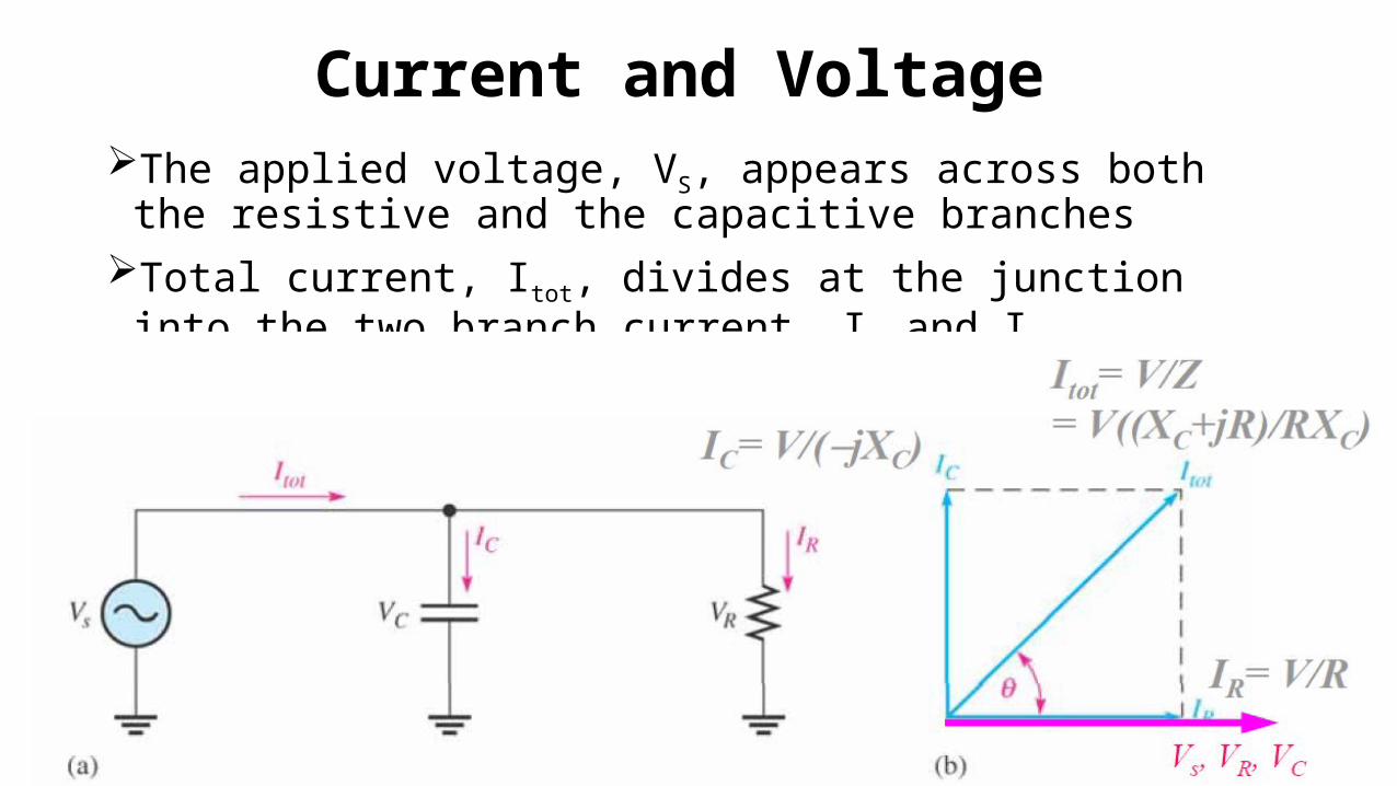
Current and Voltage The applied voltage, VS, appears across both the
resistive and the capacitive branchesTotal current, Itot, divides at the junction into the two
branch current, IR and IC
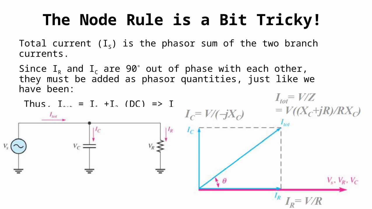
The Node Rule is a Bit Tricky!Total current (IS) is the phasor sum of the two branch currents.
Since IR and IC are 90º out of phase with each other, they must be added as phasor quantities, just like we have been:
Thus, Itot = I1 +I2 (DC) => Itot= √[IR2+ IC2] (AC) w/ θ= tan-1(IC/IR)

Example #5: Determine the value of each current, and describe the phase relationship of each with the source voltage
IR= 12/220 = 54.5 mA
IC= 12/150 = 80 mA
Itot= √(54.5)2+ (80)2= 96.8 mA
θ= tan-1(80/54.5) = 55.7