overview of european space cryogenic missions and
TRANSCRIPT

P#48
1
Overview of European Space Cryogenic Missionsand Developments in 2020 (and Beyond)
T. Tirolien, M. Linder, M. Branco
ESA-ESTEC2200 AG Noordwijk, The Netherlands
ABSTRACT
After almost 30 years of technological developments spearheaded by innovative institutes and companiesand supported by national and international agencies, space cryogenics is now a mature engineering domain,embraced by instruments and payload designers. This state of affair leads to a multiplication of missions invarious stages of development that require cryocooling solutions in various forms and sizes and with a vastarray of specificities. It is an exciting time to be involved in space cryogenics.
After a rapid rundown of the major historical European space cryogenic missions, this paper describesthe cryogenic aspects of European missions currently in-orbit, in development, or in preparation. Thedriving requirements will be spelled out as well as the associated baseline and alternative solutions.
Finally, the paper lays out the current landscape of space cryogenic developments in Europe.
INTRODUCTION
Created in 1975, the European Space Agency has been involved since its beginnings in Cryogenicmissions. InfraRed detection being a pressing need for Earth Observation, the spearheading missionsoriginate from this domain. Picking up from CNES, then ESRO developments, ESA launched in 1977 thefirst Meteosat satellite. The spacecraft not only revolutionized weather forecasting for Europe, but wasalso the first incursion of Europe in Space Cryogenics: the MVIRI instrument used HgCdTe detectorscooled at 90K by a passive system. An important page of European, but also global Space Cryogenics,was turned in 1991 with the launch of ISAMS onboard UARS (NASA) and ATSR onboard ERS-1(ESA) (Fig. 1). The University of Oxford (GB) and RAL (GB) designed a compact 80K split StirlingCooler based on the clearance seal/diaphragm spring solution which virtually removed all rubbing surfacesfrom the mechanism: for the first time, the long lifetime Space Cryogenics dream became a reality. On theScientific front, as described in C. Jewell paper [1], most of the early Research and Development effort forCryogenics of the European Space Agency was devoted to the development of the Superfluid HeliumCooling for the Infrared Space Observatory which was launched in 1995.
The end of the 1990’s and early 2000’s saw in parallel the democratization of the long-life StirlingOxford-Style Cooler for Space (more than 20 flight units delivered worldwide, Gibson [2]) and themultiplication of developments in the promising field of Pulse Tube Cooling. This period culminated in 2009by the dual launch of Herschel and Planck. Those two ESA satellites symbolize the turning point that thetechnical field was going through: 1) Herschel was the last large European dewar-based cryogenic missionto date, while 2) Planck was the first in-orbit demonstration of a complex cryochain that combines passivecooling and closed-cycle cryocoolers to provide cooling from room temperature to <1 K.
Cryocoolers 21, edited by R.G. Ross, Jr., J.R. Raab and S.D. Miller© International Cryocooler Conference, Inc., Boulder, CO, 2021 1

P#48
2
Following this ‘Golden Age’, what were the European Space Cryogenic missions that flew in the post2009 period? What do the missions in development and in preparation look like?
EUROPEAN CRYOGENIC IN-ORBIT MISSION PERFORMANCE
Cryogenic Missions Launched since 2009
Table 1 lists all the European space missions with significant Cryogenic elements that have beenlaunched since 2009.
Figure 1. ERS-1/ERS-2 (left) and ISO (right) illustrate the early steps of Europe in Space Cryogenics in thedomains of Earth Observation and Science.
Table 1. List of European Cryogenic Missions launched since 2009. In green are the missions that will betackled in the paper.
P#48
3The following points can be noted:
• With 14 cryogenics spacecraft launched, the last 10 years totals the same number of cryogenicmissions than in the period 1999 – 2009.
• However, since 2009 only four actively cooled missions (cumulating seven flight coolers) were launched,whereas in the previous period, seven missions required mechanical coolers for a total of 16 flightmechanisms.
• In both periods, the bulk of the missions comes from the Earth Observation domain.
The significant discrepancy in the number of actively cooled missions between the two periods can beexplained by two phenomena:
1) The 2000-2010 period corresponds to the end of major development cycles (Envisat, Herschel/Planck, Metop, MSG). Due to the time constants in the sector, follow-up missions (which also wouldrequire active cryocooling) were not launched in the decade that follows, but will be launched in the 2020’s.
2) Technologically, this period corresponds also to the end of a cycle: from 2000 to 2010 the effort onStirling Coolers was focused on industrialization, lifetime confirmation, and supplying the demand.Pulse Tube Cooler technology was maturing, but not yet qualified. The portfolio of ‘off-the shelf’coolers was limited and hindered by the industrial reorganization that Astrium UK underwent in 1999(move from Bristol to Stevenage).
To illustrate these points, the following two in-orbit missions are discussed in more detail: 1) Sentinel 3,the latest launched ESA spacecraft with Active Cryocooling, and 2) Sentinel 5p, the latest (nonrecurrent)launched ESA spacecraft with Passive Cryocooling.
In-Orbit Performance of Sentinel 3
SENTINEL-3 is a European Earth Observation satellite mission developed by ESA as part of theEuropean Commission’s Copernicus program. The main objective of the SENTINEL-3 mission is tomeasure sea surface topography, sea and land surface temperature, and ocean and land surface color withhigh accuracy and reliability to support ocean forecasting systems, environmental monitoring and climatemonitoring. The mission definition is driven by the need for continuity in provision of ERS, ENVISAT andSPOT vegetation data, with improvements in instrument performance and coverage.
The four main instruments are Ocean and Land Colour Instrument (OLCI), SAR Radar Altimeter(SRAL), Microwave Radiometer (MWR) and Sea and Land Surface Temperature instrument (SLSTR).As the only Cryogenic instrument of the suite, SLSTR from Leonardo (IT) will be the subject of the nextparagraphs.
The SLSTR instrument is a high accuracy radiometer, which represents the successor of the (A)ATSRfamily. It is comprised of two elements: the SLSTR Optical Scanning Unit (SLOSU) and theControl&Processor Electronics (CPE). The SLOSU (Fig. 2) includes the Detection Assembly (DA),which contains the Focal Plane Assembly (FPA) and the Cryocooler System (CCS), Coppo [3].
Figure 2. The schematic of the SLOSU (left – courtesy Leonardo) shows the Cryocooler System location(right – courtesy Airbus DS ltd) used to achieve the ~85 K detector temperature.
AEROSPACE APPLICATIONS2

P#48
2
Following this ‘Golden Age’, what were the European Space Cryogenic missions that flew in the post2009 period? What do the missions in development and in preparation look like?
EUROPEAN CRYOGENIC IN-ORBIT MISSION PERFORMANCE
Cryogenic Missions Launched since 2009
Table 1 lists all the European space missions with significant Cryogenic elements that have beenlaunched since 2009.
Figure 1. ERS-1/ERS-2 (left) and ISO (right) illustrate the early steps of Europe in Space Cryogenics in thedomains of Earth Observation and Science.
Table 1. List of European Cryogenic Missions launched since 2009. In green are the missions that will betackled in the paper.
P#48
3The following points can be noted:
• With 14 cryogenics spacecraft launched, the last 10 years totals the same number of cryogenicmissions than in the period 1999 – 2009.
• However, since 2009 only four actively cooled missions (cumulating seven flight coolers) were launched,whereas in the previous period, seven missions required mechanical coolers for a total of 16 flightmechanisms.
• In both periods, the bulk of the missions comes from the Earth Observation domain.
The significant discrepancy in the number of actively cooled missions between the two periods can beexplained by two phenomena:
1) The 2000-2010 period corresponds to the end of major development cycles (Envisat, Herschel/Planck, Metop, MSG). Due to the time constants in the sector, follow-up missions (which also wouldrequire active cryocooling) were not launched in the decade that follows, but will be launched in the 2020’s.
2) Technologically, this period corresponds also to the end of a cycle: from 2000 to 2010 the effort onStirling Coolers was focused on industrialization, lifetime confirmation, and supplying the demand.Pulse Tube Cooler technology was maturing, but not yet qualified. The portfolio of ‘off-the shelf’coolers was limited and hindered by the industrial reorganization that Astrium UK underwent in 1999(move from Bristol to Stevenage).
To illustrate these points, the following two in-orbit missions are discussed in more detail: 1) Sentinel 3,the latest launched ESA spacecraft with Active Cryocooling, and 2) Sentinel 5p, the latest (nonrecurrent)launched ESA spacecraft with Passive Cryocooling.
In-Orbit Performance of Sentinel 3
SENTINEL-3 is a European Earth Observation satellite mission developed by ESA as part of theEuropean Commission’s Copernicus program. The main objective of the SENTINEL-3 mission is tomeasure sea surface topography, sea and land surface temperature, and ocean and land surface color withhigh accuracy and reliability to support ocean forecasting systems, environmental monitoring and climatemonitoring. The mission definition is driven by the need for continuity in provision of ERS, ENVISAT andSPOT vegetation data, with improvements in instrument performance and coverage.
The four main instruments are Ocean and Land Colour Instrument (OLCI), SAR Radar Altimeter(SRAL), Microwave Radiometer (MWR) and Sea and Land Surface Temperature instrument (SLSTR).As the only Cryogenic instrument of the suite, SLSTR from Leonardo (IT) will be the subject of the nextparagraphs.
The SLSTR instrument is a high accuracy radiometer, which represents the successor of the (A)ATSRfamily. It is comprised of two elements: the SLSTR Optical Scanning Unit (SLOSU) and theControl&Processor Electronics (CPE). The SLOSU (Fig. 2) includes the Detection Assembly (DA),which contains the Focal Plane Assembly (FPA) and the Cryocooler System (CCS), Coppo [3].
Figure 2. The schematic of the SLOSU (left – courtesy Leonardo) shows the Cryocooler System location(right – courtesy Airbus DS ltd) used to achieve the ~85 K detector temperature.
OVERVIEW OF EUROPEAN SPACE CRYOGENIC MISSIONS 3

P#48
4Within the FPA, the IR and the SWIR channels are accommodated onto a cryogenic optical benchcooled at 85K by a pair of head-to-head 50-80K Stirling Coolers from Airbus DS Ltd (GB). The maindesign features related to cryogenics are the following:
• The two 50-80K Coolers are mounted onto a Cryocooler Support Structure that provides a suitablethermal and mechanical environment for the System as well as a cunning accommodation of themoving parts to passively mitigate exported vibrations.
• The Cooler Drive Electronics from CRISA (ES) possesses the following functions: active launchlock, position control loop for compressor and displacer, cold tip temperature control and activemicrovibration cancellation.
• The Cold Tips of the Stirling Coolers are connected to the FPA InfraRed Optical Bench via two HighPurity Aluminum Thermal Link Assemblies.
• The IR OB is supported by GFRP struts and enclosed in a Low Emissivity Can , which in flight isconnected to deep space via the so-called venting snorkel. On ground, the entire FPA can be evacu-ated for ground testing purposes.
Launched the 16th of February 2016, SLSTR on Sentinel 3A has been performing exceptionally well[4][5][6]. There have been no major anomalies, and availability gaps are due to ground station issues,maneuvers, calibration observations or decontamination. It is interesting to note that due to early CDEblips, which caused impromptu transitions to STANDBY mode, it has been decided to disable the vibrationcontrol loop of the cooler system, without impact on the performance of the instrument.
The Cryocooling System performs nominally. In beginning of life conditions, the thermal model correlationhas been verified with in-orbit data. When applying the thermal environment reported in telemetry to theFPA Thermal Model, the expected heat load on the cold tip at ~80K was around 1.84W. This was comparedto the heat load measured in-flight derived from the compressor stroke and only a small discrepancy of 4%(within the uncertainties of the exercise) was obtained (~1.77W at 80K was estimated in flight).
The short-term behavior of the cryocooling system as described in Figure 3 is typical. On the bottompanel we see that the radiator picks up a little bit of sun before the satellite enters eclipse, thus its temperaturevaries sensibly during the orbit (from -8ºC to 2ºC). This 10ºC temperature excursion is damped to 5ºC at
Figure 3. Examples of in-orbit data of daily variation of compressor currents, compressor temperatures,piston stroke, and compressor radiator temperature.
P#48
5
the compressors/displacers level. The variation of interface temperature of the cooler affects slightly itsefficiency, and — as the cold tip temperature is actively controlled in closed loop on the piston stroke tomaintain a target temperature — this variation of efficiency is reflected on the piston stroke and currents:when the coolers get hotter, the stroke increases.
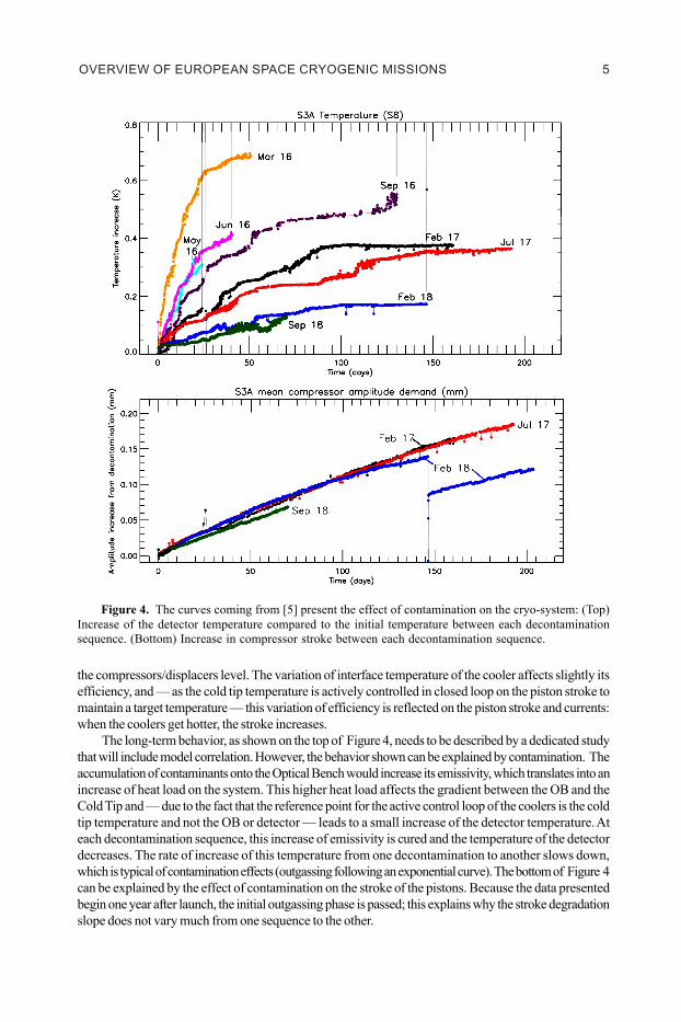
The long-term behavior, as shown on the top of Figure 4, needs to be described by a dedicated studythat will include model correlation. However, the behavior shown can be explained by contamination. Theaccumulation of contaminants onto the Optical Bench would increase its emissivity, which translates into anincrease of heat load on the system. This higher heat load affects the gradient between the OB and theCold Tip and — due to the fact that the reference point for the active control loop of the coolers is the coldtip temperature and not the OB or detector — leads to a small increase of the detector temperature. Ateach decontamination sequence, this increase of emissivity is cured and the temperature of the detectordecreases. The rate of increase of this temperature from one decontamination to another slows down,which is typical of contamination effects (outgassing following an exponential curve). The bottom of Figure 4can be explained by the effect of contamination on the stroke of the pistons. Because the data presentedbegin one year after launch, the initial outgassing phase is passed; this explains why the stroke degradationslope does not vary much from one sequence to the other.
Figure 4. The curves coming from [5] present the effect of contamination on the cryo-system: (Top)Increase of the detector temperature compared to the initial temperature between each decontaminationsequence. (Bottom) Increase in compressor stroke between each decontamination sequence.
AEROSPACE APPL ICAT IONS4
P#48
4Within the FPA, the IR and the SWIR channels are accommodated onto a cryogenic optical benchcooled at 85K by a pair of head-to-head 50-80K Stirling Coolers from Airbus DS Ltd (GB). The maindesign features related to cryogenics are the following:
• The two 50-80K Coolers are mounted onto a Cryocooler Support Structure that provides a suitablethermal and mechanical environment for the System as well as a cunning accommodation of themoving parts to passively mitigate exported vibrations.
• The Cooler Drive Electronics from CRISA (ES) possesses the following functions: active launchlock, position control loop for compressor and displacer, cold tip temperature control and activemicrovibration cancellation.
• The Cold Tips of the Stirling Coolers are connected to the FPA InfraRed Optical Bench via two HighPurity Aluminum Thermal Link Assemblies.
• The IR OB is supported by GFRP struts and enclosed in a Low Emissivity Can , which in flight isconnected to deep space via the so-called venting snorkel. On ground, the entire FPA can be evacu-ated for ground testing purposes.
Launched the 16th of February 2016, SLSTR on Sentinel 3A has been performing exceptionally well[4][5][6]. There have been no major anomalies, and availability gaps are due to ground station issues,maneuvers, calibration observations or decontamination. It is interesting to note that due to early CDEblips, which caused impromptu transitions to STANDBY mode, it has been decided to disable the vibrationcontrol loop of the cooler system, without impact on the performance of the instrument.
The Cryocooling System performs nominally. In beginning of life conditions, the thermal model correlationhas been verified with in-orbit data. When applying the thermal environment reported in telemetry to theFPA Thermal Model, the expected heat load on the cold tip at ~80K was around 1.84W. This was comparedto the heat load measured in-flight derived from the compressor stroke and only a small discrepancy of 4%(within the uncertainties of the exercise) was obtained (~1.77W at 80K was estimated in flight).
The short-term behavior of the cryocooling system as described in Figure 3 is typical. On the bottompanel we see that the radiator picks up a little bit of sun before the satellite enters eclipse, thus its temperaturevaries sensibly during the orbit (from -8ºC to 2ºC). This 10ºC temperature excursion is damped to 5ºC at
Figure 3. Examples of in-orbit data of daily variation of compressor currents, compressor temperatures,piston stroke, and compressor radiator temperature.
P#48
5
the compressors/displacers level. The variation of interface temperature of the cooler affects slightly itsefficiency, and — as the cold tip temperature is actively controlled in closed loop on the piston stroke tomaintain a target temperature — this variation of efficiency is reflected on the piston stroke and currents:when the coolers get hotter, the stroke increases.
The long-term behavior, as shown on the top of Figure 4, needs to be described by a dedicated studythat will include model correlation. However, the behavior shown can be explained by contamination. Theaccumulation of contaminants onto the Optical Bench would increase its emissivity, which translates into anincrease of heat load on the system. This higher heat load affects the gradient between the OB and theCold Tip and — due to the fact that the reference point for the active control loop of the coolers is the coldtip temperature and not the OB or detector — leads to a small increase of the detector temperature. Ateach decontamination sequence, this increase of emissivity is cured and the temperature of the detectordecreases. The rate of increase of this temperature from one decontamination to another slows down,which is typical of contamination effects (outgassing following an exponential curve). The bottom of Figure 4can be explained by the effect of contamination on the stroke of the pistons. Because the data presentedbegin one year after launch, the initial outgassing phase is passed; this explains why the stroke degradationslope does not vary much from one sequence to the other.
Figure 4. The curves coming from [5] present the effect of contamination on the cryo-system: (Top)Increase of the detector temperature compared to the initial temperature between each decontaminationsequence. (Bottom) Increase in compressor stroke between each decontamination sequence.
OVERVIEW OF EUROPEAN SPACE CRYOGENIC MISSIONS 5

P#48
6
In-Orbit Performances of Sentinel-5P
Sentinel-5 Precursor (shown in Fig 5) —the fruit of the collaboration between ESA, the EuropeanUnion and the Netherlands Space Office —is the first Copernicus mission dedicated to monitoring theatmosphere. The sole instrument, TROPOspheric MOnitoring Instrument (TROPOMI), performsatmospheric measurements with high spatial resolution to be used for air quality and climate monitoring &forecasting. TROPOMI features a three-stage radiant cooler. This cooler offers room-temperature coolingfor the instrument Front End Electronics and UVN optical bench, cooling down to 205 K for the UVNdetectors and SWIR optical bench, and cooling down to 140 K for the SWIR detector, Zevenbergen [7].
Sentinel 5-P was launched the 13th of October 2017. As shown on the top-left of Figure 6, followinga 3-week decontamination period, the Earth Shade door opened on November 7, 2017. The coldeststage of the radiant cooler reached its target temperature in merely 16 hours. As it can be seen on themiddle curves, the week of thermal commissioning was devoted to the fine-tuning of the active thermalcontrol of the intermediate stage. The radiant cooler was pronounced commissioned on the 13th of November2017 and has maintained outstanding performance to this date. In particular, the temperature stabilitiesobtained are excellent and well beyond the requirements (e.g. 10mK peak to peak is obtained on theSWIR detector for 80 mK required).
Another remarkable performance of TROPOMI’s radiant cooler is its long-term behavior. As presentedin Figure 7, the head room for active thermal controllability of the cold radiator decreased by less than 2%in 2.5 years. This should guarantee the required temperature and stability far beyond the 7-year mission.
Figure 6. Temperature of the radiant cooler from launch until the end of the thermal commissioning. Zerodays is midnight, November 7, 2017.
Figure 5. This artist view of Sentinel-5P shows how the radiant cooler looks like after opening of theEarth shade door, which protects from contamination and limits heat losses during launch.
P#48
7
EUROPEAN CRYOGENIC MISSIONS IN DEVELOPMENT
Even though it is clear that new types of uses are appearing on the horizon (e.g. In Situ Resource Utilization,RBO/ZBO), most of space cryogenics applications concern either Earth Observation or Scientific focal planecooling. The paper next examines the European missions currently on the books in these two domains.
Earth Observation Cryogenic Missions in Development in Europe
As alluded to in the first part of this paper, we can see in Table 2 that the 2020’s decade will see thelaunch of the newest generation of two important families of European Earth Observation Satellites: MeteosatThird Generation, and MetOp-SG. Those two sets of spacecraft will require 24 flight models of cryocoolers.Along with these two heavyweights, Copernicus Expansion — which began its implementation in 2018 —brings the total to three missions that require cryogenics, including one that needs mechanical coolers.
Table 2. List of European Cryogenic Earth Observation Missions in study or development.In green are the three missions that will be addressed in the paper.
Figure 7. Long-term evolution of the SWIR detector Duty Cycle (courtesy Airbus DS NL)
AEROSPACE APPL ICAT IONS6

P#48
6
In-Orbit Performances of Sentinel-5P
Sentinel-5 Precursor (shown in Fig 5) —the fruit of the collaboration between ESA, the EuropeanUnion and the Netherlands Space Office —is the first Copernicus mission dedicated to monitoring theatmosphere. The sole instrument, TROPOspheric MOnitoring Instrument (TROPOMI), performsatmospheric measurements with high spatial resolution to be used for air quality and climate monitoring &forecasting. TROPOMI features a three-stage radiant cooler. This cooler offers room-temperature coolingfor the instrument Front End Electronics and UVN optical bench, cooling down to 205 K for the UVNdetectors and SWIR optical bench, and cooling down to 140 K for the SWIR detector, Zevenbergen [7].
Sentinel 5-P was launched the 13th of October 2017. As shown on the top-left of Figure 6, followinga 3-week decontamination period, the Earth Shade door opened on November 7, 2017. The coldeststage of the radiant cooler reached its target temperature in merely 16 hours. As it can be seen on themiddle curves, the week of thermal commissioning was devoted to the fine-tuning of the active thermalcontrol of the intermediate stage. The radiant cooler was pronounced commissioned on the 13th of November2017 and has maintained outstanding performance to this date. In particular, the temperature stabilitiesobtained are excellent and well beyond the requirements (e.g. 10mK peak to peak is obtained on theSWIR detector for 80 mK required).
Another remarkable performance of TROPOMI’s radiant cooler is its long-term behavior. As presentedin Figure 7, the head room for active thermal controllability of the cold radiator decreased by less than 2%in 2.5 years. This should guarantee the required temperature and stability far beyond the 7-year mission.
Figure 6. Temperature of the radiant cooler from launch until the end of the thermal commissioning. Zerodays is midnight, November 7, 2017.
Figure 5. This artist view of Sentinel-5P shows how the radiant cooler looks like after opening of theEarth shade door, which protects from contamination and limits heat losses during launch.
P#48
7
EUROPEAN CRYOGENIC MISSIONS IN DEVELOPMENT
Even though it is clear that new types of uses are appearing on the horizon (e.g. In Situ Resource Utilization,RBO/ZBO), most of space cryogenics applications concern either Earth Observation or Scientific focal planecooling. The paper next examines the European missions currently on the books in these two domains.
Earth Observation Cryogenic Missions in Development in Europe
As alluded to in the first part of this paper, we can see in Table 2 that the 2020’s decade will see thelaunch of the newest generation of two important families of European Earth Observation Satellites: MeteosatThird Generation, and MetOp-SG. Those two sets of spacecraft will require 24 flight models of cryocoolers.Along with these two heavyweights, Copernicus Expansion — which began its implementation in 2018 —brings the total to three missions that require cryogenics, including one that needs mechanical coolers.
Table 2. List of European Cryogenic Earth Observation Missions in study or development.In green are the three missions that will be addressed in the paper.
Figure 7. Long-term evolution of the SWIR detector Duty Cycle (courtesy Airbus DS NL)
OVERVIEW OF EUROPEAN SPACE CRYOGENIC MISSIONS 7

P#48
8 Lastly, one can note that the promise of (very) small satellites requiring cryogenics seems to havefinally come to fruition with missions like TANGO or LOCUS.
Example of Cryogenic EO Mission in Development in Europe: MTG
Meteosat Third Generation is the next-generation of European operational geostationary meteorologicalsatellite system undertaken in the frame of a cooperation agreement between ESA and EUMETSAT. It iscomposed of two types of satellites:
1) Four imaging Satellites (MTG-I) embarking two optical payloads (Flexible Combined Imagerand Lightning Imager) and one communication payload (DCS&SAR). FCI and DCS&SAR arecontinuation of MSG mission.
2) Two sounder Satellites (MTG-S) embarking two sounding payloads: the InfraRed Sounder (IRS)and the Copernicus Sentinel 4 UVN.
The main features of the two types of Spacecraft are described hereafter:• MTG-I, prime TAS-F (FR):
o Total mass ~3.6t, FCI mass ~450kg.o Total power budget ~2.2kW, FCI power consumption ~500W.o 3-axis Stabilized GEO platform.o HgCdTe Detectors to be cooled at 58Ko Lifetime requirement: 8.5 years.o First launch: Q4 2022.
• MTG-S, prime OHB (DE):o Total mass ~3.8t, IRS mass ~500kg.o Total power budget ~2.2kW, IRS power consumption ~800W.o 3-axis Stabilized GEO platform.o HgCdTe Detectors to be cooled at 55Ko Lifetime requirement: 8.5 years.o First launch: Q4 2023
In the years 2004-2005, the Pre-phase A studies conducted within ESA based upon the high leveluser needs identified Cryogenics (~3W at 50K) as one of the technological drivers. That prompted thelaunch of two technological development activities: the Large Pulse Tube Cooler of ALAT (FR) and theHigh Power Stirling Cooler of Airbus DS ltd (GB). In 2012, the LPTC of ALAT was selected as thetechnical baseline to cool down the detectors of both FCI and IRS.
In addition to the Cryocooler System, for which you can find more details in the paper of T. Wiertz[8], the following building blocks are key elements of the cryogenic architecture (common for IRS andFCI):
• Both FPAs are accommodated into Cryostats coming from Frentech (CZ) covered with PhysicalVapour Deposited Gold coating that guarantees an emissivity lower than 0.027.
• The cryocoolers in cold redundancy are connected to the detectors and cold optics via High purityaluminium Thermal Link Assemblies from Absolut System (FR).
• The Coolers are connected to radiator assemblies provided by Iberespacio (ES) in order to guaranteethe required interface temperatures (0ºC for FCI and -10ºC for IRS).
• In order to mitigate the effect of the little exported microvibrations coming from the coolers, they areaccommodated on sophisticated Cryocooler Structures that include Elastomeric Suspension Elements.
At the time of writing of this paper (January 2021), the status of the hardware is as follows:
• All the Cryocooler Units for both FCI and IRS have been manufactured and tested and exceedcryogenic commitments by a significant margin (between +6 and +10% more efficient than theEMs). The solar vacuum testing is illustrated in Figure 8. The microvibration performance is alsoexcellent and consistent across all coolers thanks to the significant manufacturing efforts deployed byTCBV (NL).
• The PFM of the first FCI has been assembled and is being tested in order to be delivered to thesatellite in 2021. The Detector Chain and Electronics Assembly has been characterized which con-firms the excellent behavior of the PFM Cryocooler System.
P#48
9
• The AIT of the PFM of the Detector Electronics Assembly and Interferometer Assembly (IA DEA)of IRS is ongoing. The EM testing held in 2018-2019 demonstrated the adequacy of the cryogenicdesign.
Example of Cryogenic EO Mission in Development in Europe: Trishna
The Thermal infrared Imaging Satellite for High-resolution Natural resource Assessment (TRISHNA)is a cooperation between CNES (FR) and ISRO (IN) with the objective to monitor at a global scale:
• Ecosystem stress and water use (i.e. monitoring of energy and water budgets of the continentalbiosphere, evapotranspiration)
• Coastal and inland waters (mesoscale, sub mesoscale dynamics, processes)
The TRISHNA payload is composed of:o The VNIR-SWIR instrument under ISRO responsibility.o The TIR instrument under the CNES responsibility.
The key features of this medium sized satellite are described hereafter:o Total mass: ~1t (<295kg for the TIR instrument)o Solar Array sizing: ~2kW (<265W for the TIR instrument)o Launch year: 2025.
Airbus DS (FR) was awarded the contract for the TIR instrument development in April 2020 andproposes a concept (Figure 9) that allies innovation and cost effectiveness. In particular, Focal Planecooling (58 K required for the detector) is provided by two LPT6510 coolers from TCBV (NL) in hotredundancy, and the Cryostat is additionally manufactured. One of the underlying concepts of the ALMCryostat design proposed by Airbus ( Figure 10) is to have a single monolithic piece of titanium bridgefrom the Instrument optical bench interface to the detector interface, thus simplifying mounting and alignment.
Figure 8. (Left) The FCI STM solar vacuum testing in 2018 at ESTEC demonstrated the performance ofthe Cryogenic System. (Right) The STM of the IRS has been vacuum tested in August 2019. The cryogenicperformance was demonstrated during the IA DEA EM test in 2018.
Figure 9. The compact TRISHNA IR instrument is based on a full AlSi design for the optical bench and thetelescope.
AEROSPACE APPL ICAT IONS8

P#48
8 Lastly, one can note that the promise of (very) small satellites requiring cryogenics seems to havefinally come to fruition with missions like TANGO or LOCUS.
Example of Cryogenic EO Mission in Development in Europe: MTG
Meteosat Third Generation is the next-generation of European operational geostationary meteorologicalsatellite system undertaken in the frame of a cooperation agreement between ESA and EUMETSAT. It iscomposed of two types of satellites:
1) Four imaging Satellites (MTG-I) embarking two optical payloads (Flexible Combined Imagerand Lightning Imager) and one communication payload (DCS&SAR). FCI and DCS&SAR arecontinuation of MSG mission.
2) Two sounder Satellites (MTG-S) embarking two sounding payloads: the InfraRed Sounder (IRS)and the Copernicus Sentinel 4 UVN.
The main features of the two types of Spacecraft are described hereafter:• MTG-I, prime TAS-F (FR):
o Total mass ~3.6t, FCI mass ~450kg.o Total power budget ~2.2kW, FCI power consumption ~500W.o 3-axis Stabilized GEO platform.o HgCdTe Detectors to be cooled at 58Ko Lifetime requirement: 8.5 years.o First launch: Q4 2022.
• MTG-S, prime OHB (DE):o Total mass ~3.8t, IRS mass ~500kg.o Total power budget ~2.2kW, IRS power consumption ~800W.o 3-axis Stabilized GEO platform.o HgCdTe Detectors to be cooled at 55Ko Lifetime requirement: 8.5 years.o First launch: Q4 2023
In the years 2004-2005, the Pre-phase A studies conducted within ESA based upon the high leveluser needs identified Cryogenics (~3W at 50K) as one of the technological drivers. That prompted thelaunch of two technological development activities: the Large Pulse Tube Cooler of ALAT (FR) and theHigh Power Stirling Cooler of Airbus DS ltd (GB). In 2012, the LPTC of ALAT was selected as thetechnical baseline to cool down the detectors of both FCI and IRS.
In addition to the Cryocooler System, for which you can find more details in the paper of T. Wiertz[8], the following building blocks are key elements of the cryogenic architecture (common for IRS andFCI):
• Both FPAs are accommodated into Cryostats coming from Frentech (CZ) covered with PhysicalVapour Deposited Gold coating that guarantees an emissivity lower than 0.027.
• The cryocoolers in cold redundancy are connected to the detectors and cold optics via High purityaluminium Thermal Link Assemblies from Absolut System (FR).
• The Coolers are connected to radiator assemblies provided by Iberespacio (ES) in order to guaranteethe required interface temperatures (0ºC for FCI and -10ºC for IRS).
• In order to mitigate the effect of the little exported microvibrations coming from the coolers, they areaccommodated on sophisticated Cryocooler Structures that include Elastomeric Suspension Elements.
At the time of writing of this paper (January 2021), the status of the hardware is as follows:
• All the Cryocooler Units for both FCI and IRS have been manufactured and tested and exceedcryogenic commitments by a significant margin (between +6 and +10% more efficient than theEMs). The solar vacuum testing is illustrated in Figure 8. The microvibration performance is alsoexcellent and consistent across all coolers thanks to the significant manufacturing efforts deployed byTCBV (NL).
• The PFM of the first FCI has been assembled and is being tested in order to be delivered to thesatellite in 2021. The Detector Chain and Electronics Assembly has been characterized which con-firms the excellent behavior of the PFM Cryocooler System.
P#48
9
• The AIT of the PFM of the Detector Electronics Assembly and Interferometer Assembly (IA DEA)of IRS is ongoing. The EM testing held in 2018-2019 demonstrated the adequacy of the cryogenicdesign.
Example of Cryogenic EO Mission in Development in Europe: Trishna
The Thermal infrared Imaging Satellite for High-resolution Natural resource Assessment (TRISHNA)is a cooperation between CNES (FR) and ISRO (IN) with the objective to monitor at a global scale:
• Ecosystem stress and water use (i.e. monitoring of energy and water budgets of the continentalbiosphere, evapotranspiration)
• Coastal and inland waters (mesoscale, sub mesoscale dynamics, processes)
The TRISHNA payload is composed of:o The VNIR-SWIR instrument under ISRO responsibility.o The TIR instrument under the CNES responsibility.
The key features of this medium sized satellite are described hereafter:o Total mass: ~1t (<295kg for the TIR instrument)o Solar Array sizing: ~2kW (<265W for the TIR instrument)o Launch year: 2025.
Airbus DS (FR) was awarded the contract for the TIR instrument development in April 2020 andproposes a concept (Figure 9) that allies innovation and cost effectiveness. In particular, Focal Planecooling (58 K required for the detector) is provided by two LPT6510 coolers from TCBV (NL) in hotredundancy, and the Cryostat is additionally manufactured. One of the underlying concepts of the ALMCryostat design proposed by Airbus ( Figure 10) is to have a single monolithic piece of titanium bridgefrom the Instrument optical bench interface to the detector interface, thus simplifying mounting and alignment.
Figure 8. (Left) The FCI STM solar vacuum testing in 2018 at ESTEC demonstrated the performance ofthe Cryogenic System. (Right) The STM of the IRS has been vacuum tested in August 2019. The cryogenicperformance was demonstrated during the IA DEA EM test in 2018.
Figure 9. The compact TRISHNA IR instrument is based on a full AlSi design for the optical bench and thetelescope.
OVERVIEW OF EUROPEAN SPACE CRYOGENIC MISSIONS 9

P#48
10
Example of Cryogenic EO Mission in Study in Europe: TANGO
Twin ANthropogenic Greenhouse gas Observers (TANGO) is part of ESA’s SCOUT initiative, whichembraces the ‘New Space’ paradigm to develop reduced budget (30MEURO) Earth Observation ResearchMissions. Two ideas motivate ESA to pursue this approach:
1) The possibility to compliment classical institutional missions with high revisit times constellations,
2) The opportunity to easily and quickly demonstrate in-orbit technologies.
In the case of TANGO, one of the objectives of the mission is to complement Sentinel 5 and CopernicusCO2M observation for the verification of the Paris agreement and global stock takes. Some of the othergoals are (Pastena [9]):
• NO2 observations at high spatial resolution,
• Exploit the use of CO2/NO2 ratio observations to estimate CO2 emissions from offshore NO2 sources,
• Demonstrate a distributed monitoring system that can pave the way to future larger constellationsallowing for enhanced coverage and temporal resolution.
TANGO is based on two push-broom spectrometers each flying on the ISIS (NL) 16U CubeSatplatform. One of the spectrometer concerns CO2 monitoring and requires a cutoff wavelength at1.6 micrometers. If the detector selected is HgCdTe based, it will need cooling at around 150 K. However,unlike comparable bigger missions like CO2M or Sentinel 5, passive cooling cannot be an option due tothe limited volume available and the fact that the satellite relies on forward motion compensation (pitchmaneuver to improve observation quality). Consequently, it is very likely that, if selected, TANGO will relyon microcooler(s) (potentially with IDCA) for its focal plane cooling.
Science Cryogenic Missions in Study or Development in Europe
Table 3 lists the Cryogenic missions in the Science domains that are currently in development orenvisaged. It has to be noted that it is very likely that this list will expand based on the new call from ESAfor Scientific missions, Voyage 2050, will happen in 2021. It is expected that several of the proposedmission concepts will require cryogenic cooling.
Example of Cryogenic Scientific Mission in study in Europe: ARIEL
The Atmospheric Remote-sensing Infrared Exoplanet Large-survey (ARIEL) mission (Fig. 11) hasjust been approved for implementation (ph. B2/C/D) in the frame of the ESA Cosmic Vision M4 program.It will perform a spectroscopy survey of hundreds of transiting planets, spanning different planetary sizes,a range of equilibrium temperatures and orbiting a variety of stellar types. As explained in the ARIELDefinition Study Report [10], multiple methods—amongst with the transit and the eclipse methods—areused to probe the atmosphere of the exoplanets, using the wide wavelength coverage (1.95 μm to 7.8 μm)of the Ariel IR Spectrograph (AIRS).
Figure 10. The ALM Cryostat (left) is made out of three different pieces and shall guarantee <1W of parasiticson the detector. A first BB of the Cryostat (right) has been manufactured. Court. Airbus DS
P#48
11
From the Thermal and Cryogenics point of view, the driving requirements coming from the ARIELPayload are the following:
• The aluminum mirrors need to be maintained at a temperature < 70K in operation,
• The FGS Detectors need to be maintained at a temperature <70K in operation,
• The Cold Optics for both AIRS and the FGS need to be maintained at a temperature <60 K inoperation
• The AIRS detectors need to be maintained at a temperature <42K in operation.
To tackle those challenging requirements, ARIEL uses a thermal architecture “à-la Planck”:
• The Cold Payload Module is mounted on a warm Service Module but is thermally decoupled using aset of three V-Grooves and low conductivity BiPods.
• The remaining parasitics coming from the SVM and the internal dissipations of the Cold PLM arerejected to space using a large surface area covered with a high-emissivity coating: the upper surfaceof the third V-Grooves, the Telescope Baffle, and the dedicated Instrument Radiator mounted on topof the Optical Bench.
Table 3. List of European Cryogenic Scientific Missions in study or development. In green are the twomissions that will be addressed in the paper.
Figure 11. The ARIEL Spacecraft and its main payload elements (court. Ariel Mission Consortium).
AEROSPACE APPL ICAT IONS1 0

P#48
10
Example of Cryogenic EO Mission in Study in Europe: TANGO
Twin ANthropogenic Greenhouse gas Observers (TANGO) is part of ESA’s SCOUT initiative, whichembraces the ‘New Space’ paradigm to develop reduced budget (30MEURO) Earth Observation ResearchMissions. Two ideas motivate ESA to pursue this approach:
1) The possibility to compliment classical institutional missions with high revisit times constellations,
2) The opportunity to easily and quickly demonstrate in-orbit technologies.
In the case of TANGO, one of the objectives of the mission is to complement Sentinel 5 and CopernicusCO2M observation for the verification of the Paris agreement and global stock takes. Some of the othergoals are (Pastena [9]):
• NO2 observations at high spatial resolution,
• Exploit the use of CO2/NO2 ratio observations to estimate CO2 emissions from offshore NO2 sources,
• Demonstrate a distributed monitoring system that can pave the way to future larger constellationsallowing for enhanced coverage and temporal resolution.
TANGO is based on two push-broom spectrometers each flying on the ISIS (NL) 16U CubeSatplatform. One of the spectrometer concerns CO2 monitoring and requires a cutoff wavelength at1.6 micrometers. If the detector selected is HgCdTe based, it will need cooling at around 150 K. However,unlike comparable bigger missions like CO2M or Sentinel 5, passive cooling cannot be an option due tothe limited volume available and the fact that the satellite relies on forward motion compensation (pitchmaneuver to improve observation quality). Consequently, it is very likely that, if selected, TANGO will relyon microcooler(s) (potentially with IDCA) for its focal plane cooling.
Science Cryogenic Missions in Study or Development in Europe
Table 3 lists the Cryogenic missions in the Science domains that are currently in development orenvisaged. It has to be noted that it is very likely that this list will expand based on the new call from ESAfor Scientific missions, Voyage 2050, will happen in 2021. It is expected that several of the proposedmission concepts will require cryogenic cooling.
Example of Cryogenic Scientific Mission in study in Europe: ARIEL
The Atmospheric Remote-sensing Infrared Exoplanet Large-survey (ARIEL) mission (Fig. 11) hasjust been approved for implementation (ph. B2/C/D) in the frame of the ESA Cosmic Vision M4 program.It will perform a spectroscopy survey of hundreds of transiting planets, spanning different planetary sizes,a range of equilibrium temperatures and orbiting a variety of stellar types. As explained in the ARIELDefinition Study Report [10], multiple methods—amongst with the transit and the eclipse methods—areused to probe the atmosphere of the exoplanets, using the wide wavelength coverage (1.95 μm to 7.8 μm)of the Ariel IR Spectrograph (AIRS).
Figure 10. The ALM Cryostat (left) is made out of three different pieces and shall guarantee <1W of parasiticson the detector. A first BB of the Cryostat (right) has been manufactured. Court. Airbus DS
P#48
11
From the Thermal and Cryogenics point of view, the driving requirements coming from the ARIELPayload are the following:
• The aluminum mirrors need to be maintained at a temperature < 70K in operation,
• The FGS Detectors need to be maintained at a temperature <70K in operation,
• The Cold Optics for both AIRS and the FGS need to be maintained at a temperature <60 K inoperation
• The AIRS detectors need to be maintained at a temperature <42K in operation.
To tackle those challenging requirements, ARIEL uses a thermal architecture “à-la Planck”:
• The Cold Payload Module is mounted on a warm Service Module but is thermally decoupled using aset of three V-Grooves and low conductivity BiPods.
• The remaining parasitics coming from the SVM and the internal dissipations of the Cold PLM arerejected to space using a large surface area covered with a high-emissivity coating: the upper surfaceof the third V-Grooves, the Telescope Baffle, and the dedicated Instrument Radiator mounted on topof the Optical Bench.
Table 3. List of European Cryogenic Scientific Missions in study or development. In green are the twomissions that will be addressed in the paper.
Figure 11. The ARIEL Spacecraft and its main payload elements (court. Ariel Mission Consortium).
OVERVIEW OF EUROPEAN SPACE CRYOGENIC MISSIONS 1 1

P#48
12• In order to achieve the 42K required for the AIRS detectors, a Neon Joule-Thomson Cooler fromRAL STFC (GB) is baselined. This cooler draws his heritage from the He Joule-Thomson Cooler fromPlanck, with modernized mechanisms and an adapted cold plumbing due to the different working fluid.
As explained in the paper of G. Morgante [11], this design shows comfortable margins toward thetemperature levels requested. However the following challenges are still anticipated:
• Management of the interfaces: as is typically the case in ESA Science projects, the responsibility ofthe Payload elements has been shared between numerous parties. This leads to a high number ofinterfaces in technically sensitive parts (e.g. V-Grooves and BiPods, between the cryoharness and allthe PLM elements).
• Effect of Sun Illumination: being a Cryogenic PLM, the Payload Module of ARIEL is sensitive to sunintrusion. Missions phases like ascent and maneuvers need to be carefully analyzed to ensure that nofragile parts exceed their temperature limits.
• Neon Joule-Thomson Cooler Development: even though the risk for the development of the cooler isconsidered relatively low due to the expertise of the RAL team and the direct heritage of a flightproven cooler, the upcoming Engineering Model testing planned in the second half of 2021 will becrucial to demonstrate the Technology Readiness Level necessary at this stage of the project.
Example of Cryogenic Scientific Mission in Study in Europe: ATHENA
Selected in 2014 as the second Large Class mission in the frame of ESA’s Cosmic Vision, ATHENA—Advanced Telescope for High-ENergy Astrophysics—will be an X-ray telescope designed to addressthe Cosmic Vision science theme “The Hot and Energetic Universe” [10]. For European Space Cryogenics,this ambitious and extremely challenging mission is shaping up to drive the community for the coming yearsas Herschel/Planck did in the 1990’s and early 2000’s.
To achieve the mission’s science objectives, Athena carries a payload capable of spatially-resolvedX-ray spectroscopy and deep wide-field X-ray spectral imaging with performance greatly exceeding thatoffered by current X-ray observatories. Its instrumentation will consist of a cryogenic X-ray spectrometercalled the X-ray Integral Field Unit (X-IFU), and a Wide Field Imager (WFI). The main characteristics ofthe spacecraft are the following:
• Total mass: ~7t• Power budget: ~8kW• Focal length: 12m• Surface area of the X-ray mirror: 1.5m2 through combining 600 Silicon Pore Optics modules
to be maintained at 20ºC +/-5ºC• Mass of the Science Instrument Module: ~2.4t• Dissipation inside the Science Instrument Module: ~5kW.• Launch year: 2031
From the Cryogenic point of view, X-IFU represents one of the most challenging instruments to belaunched. In order to guarantee the 50 mK temperature required by the Transition Edge Sensor detectors,the following architecture is envisaged by CNES (FR):
• Outer Vessel at 300 K• Internal Passive Cooling at 200 K• Outer Cold Shield at 80 K• Inner Cold Shield at 30 K• 15K JT Precooling stage• 4K Stage• 2K Stage• 2K core (with 300 mK and 50 mK stage)
Those temperature stages are obtained thanks to a cooling-chain (Fig. 12) which is single-point-failure tolerant (except for the Sub-K cooler):
• 4x PT15K Coolers (24 kg and 300 W each)• 2x JT4K Coolers• 2x JT2K Coolers• Hybrid He-3 Sorption Cooler / ADR
P#48
13
In order to achieve the required technological maturity, ESA has been in the last 10 years fundingdevelopments corresponding to each stage of the Cryochain as well as an end-to-end demonstrator.
CONCLUSION AND LINK TO THE DEVELOPMENTS
As described in this paper, the coming years promise to be exciting for European Space Cryogenics.Indeed, cryogenic missions have never been so ambitious, numerous and diverse.
In the space sector, technology developments need to be one step ahead of the missions: TechnologyReadiness Level can make or break projects. With a standard financial commitment, a brand new
Figure 12. The concept of the active cooling chain as depicted on the left has been demonstratedthanks to the Detector Cooling Chain CTP (right) from CEA (FR). Court. CNES and CEA
AEROSPACE APPL ICAT IONS1 2

P#48
12• In order to achieve the 42K required for the AIRS detectors, a Neon Joule-Thomson Cooler fromRAL STFC (GB) is baselined. This cooler draws his heritage from the He Joule-Thomson Cooler fromPlanck, with modernized mechanisms and an adapted cold plumbing due to the different working fluid.
As explained in the paper of G. Morgante [11], this design shows comfortable margins toward thetemperature levels requested. However the following challenges are still anticipated:
• Management of the interfaces: as is typically the case in ESA Science projects, the responsibility ofthe Payload elements has been shared between numerous parties. This leads to a high number ofinterfaces in technically sensitive parts (e.g. V-Grooves and BiPods, between the cryoharness and allthe PLM elements).
• Effect of Sun Illumination: being a Cryogenic PLM, the Payload Module of ARIEL is sensitive to sunintrusion. Missions phases like ascent and maneuvers need to be carefully analyzed to ensure that nofragile parts exceed their temperature limits.
• Neon Joule-Thomson Cooler Development: even though the risk for the development of the cooler isconsidered relatively low due to the expertise of the RAL team and the direct heritage of a flightproven cooler, the upcoming Engineering Model testing planned in the second half of 2021 will becrucial to demonstrate the Technology Readiness Level necessary at this stage of the project.
Example of Cryogenic Scientific Mission in Study in Europe: ATHENA
Selected in 2014 as the second Large Class mission in the frame of ESA’s Cosmic Vision, ATHENA—Advanced Telescope for High-ENergy Astrophysics—will be an X-ray telescope designed to addressthe Cosmic Vision science theme “The Hot and Energetic Universe” [10]. For European Space Cryogenics,this ambitious and extremely challenging mission is shaping up to drive the community for the coming yearsas Herschel/Planck did in the 1990’s and early 2000’s.
To achieve the mission’s science objectives, Athena carries a payload capable of spatially-resolvedX-ray spectroscopy and deep wide-field X-ray spectral imaging with performance greatly exceeding thatoffered by current X-ray observatories. Its instrumentation will consist of a cryogenic X-ray spectrometercalled the X-ray Integral Field Unit (X-IFU), and a Wide Field Imager (WFI). The main characteristics ofthe spacecraft are the following:
• Total mass: ~7t• Power budget: ~8kW• Focal length: 12m• Surface area of the X-ray mirror: 1.5m2 through combining 600 Silicon Pore Optics modules
to be maintained at 20ºC +/-5ºC• Mass of the Science Instrument Module: ~2.4t• Dissipation inside the Science Instrument Module: ~5kW.• Launch year: 2031
From the Cryogenic point of view, X-IFU represents one of the most challenging instruments to belaunched. In order to guarantee the 50 mK temperature required by the Transition Edge Sensor detectors,the following architecture is envisaged by CNES (FR):
• Outer Vessel at 300 K• Internal Passive Cooling at 200 K• Outer Cold Shield at 80 K• Inner Cold Shield at 30 K• 15K JT Precooling stage• 4K Stage• 2K Stage• 2K core (with 300 mK and 50 mK stage)
Those temperature stages are obtained thanks to a cooling-chain (Fig. 12) which is single-point-failure tolerant (except for the Sub-K cooler):
• 4x PT15K Coolers (24 kg and 300 W each)• 2x JT4K Coolers• 2x JT2K Coolers• Hybrid He-3 Sorption Cooler / ADR
P#48
13
In order to achieve the required technological maturity, ESA has been in the last 10 years fundingdevelopments corresponding to each stage of the Cryochain as well as an end-to-end demonstrator.
CONCLUSION AND LINK TO THE DEVELOPMENTS
As described in this paper, the coming years promise to be exciting for European Space Cryogenics.Indeed, cryogenic missions have never been so ambitious, numerous and diverse.
In the space sector, technology developments need to be one step ahead of the missions: TechnologyReadiness Level can make or break projects. With a standard financial commitment, a brand new
Figure 12. The concept of the active cooling chain as depicted on the left has been demonstratedthanks to the Detector Cooling Chain CTP (right) from CEA (FR). Court. CNES and CEA
OVERVIEW OF EUROPEAN SPACE CRYOGENIC MISSIONS 1 3

P#48
14development takes ~10 years to reach TRL 6, 5 years if it is the evolution of a product. It is thereforenecessary to prepare today the technological development of missions that will be launched in 2040 –2050.
What are the main topics of ESA led development activities?
• Completing the portfolio of qualified cooler systems for Large (MTG-like) to Small (TANGO-like)missions.
• Capitalize the lessons learned of 15 years of developments by preparing the next iteration of better &cheaper coolers.
• Prepare the future Earth Observation or Science challenges by developing Vibration-Free Cooler forSpace (e.g. Reverse Turbo Brayton, Laser Cooler, Sorption Cooler).
• Embrace the New Space paradigm and develop methods to increasingly use COTS coolers on Spacemissions.
ACKNOWLEDGMENT
The author would like to acknowledge J. Tanchon and M. Crook to give me the opportunity to givethis plenary talk. I also would like to thank the following colleagues for their valuable contributions: J. Frerick(ESA), H. Rana (Oxford University), J. Doornink (Airbus DS NL), the MTG team (TAS/OHB/ESA),Stéphanie Remaury (CNES), Didier Charvet and his team (Airbus DS France), Michel Tossaint andVictor Cleren (ESA), The ARIEL Team (ESA/RAL Space/RAL STFC/INAF), Moritz Branco and MartinLinder (ESA).
REFERENCES
1. Jewell, C., “Overview of Cryogenic Development at ESA,” Proceedings of the 6th European Sympo-sium on Space Environmental Control, 1997.
2. Gibson, A., “Heritage Overview: 20 Years of Commercial Production of Cryocoolers for Space,” AIPConference Proceedings 985. 10.1063/1.2908589, 2008.
3. Coppo, P., “The Sea and Land Surface Temperature Radiometer (SLSTR) Detection Assembly Designand Performance,” Sensors, Systems, and Next-Generation Satellites XVII, edited by Roland Meynart,Steven P. Neeck, Haruhisa Shimoda, 2013, Proc. of SPIE Vol. 8889, 888914.
4. Sentinel-3 Optical Annual Performance Report - 2017
5. Sentinel-3 Optical Annual Performance Report – 2018
6. Sentinel-3 Optical Annual Performance Report – 2019
7. Zevenbergen, P. et al., “Thermal Design of the Sentinel 5 Precursor TROPOMI Instrument,” AIAAProceedings of The 42nd International Conference on Environmental Systems (ICES), 2012.
8. Wiertz, T. et al., “Qualification Status of the LPTC Cryocoolers for MTG Instruments,” Cryocoolers20, ICC Press, Boulder, Colorado (2018), pp. 127-133.
9. Pastena, M., “Overview of ESA’s Earth Observation Upcoming Small Satellites Missions,” Proceed-ings of the 34th Annual AIAA/USU Conference on Small Satellites, 2020.
10. Ariel Definition Study Report – 2020.
11. Morgante, G., “Thermal Architecture of the ESA ARIEL Payload,” Proc. SPIE 10698, Space Telescopesand Instrumentation 2018: Optical, Infrared, and Millimeter Wave.
Thermal Design of the Earth Surface Mineral Dust
Source Investigation (EMIT)
Jet Propulsion Laboratory, California Institute of Technology Pasadena, CA 91109 *Aerospace Corporation El Segundo, CA 90245
ABSTRACT
The Earth Surface Mineral Dust Source Investigation (EMIT) instrument, designed and built for NASA by the Jet Propulsion Laboratory, will map the surface mineralogy of arid source regions in the visible and short-wave infrared (VSWIR) from the International Space Station. EMIT requires a longlife mechanical cooler that provides cooling at 150 K and a heat rejection system (HRS) that can efficiently absorb, transfer, and reject instrument waste heat to space. The Thermal Control System (TCS) consists of a combination of active and passive components to maintain instrument components within the allowable flight temperature (AFT) limits. The active components include a mechanical cryocooler, heaters, and variable conductance heat pipes (VCHP). The passive TCS include multi-layer insulation, constant conductance heat pipes (CCHP) and coatings. The focal plane array (FPA) and spectrometer are cooled to 155 K and 240 K, respectively, by a single-stage split Stirling linear pulse tube cryocooler (LPT9310), powered by HP-LCCE2 electronics. High performance Pyrolytic Graphite Sheet (PGS) thermal links are used to transport operational and parasitic heat loads from the FPA and spectrometer to the cooler cold tip. This paper provides an overview of the EMIT instrument TCS architecture, cryocooler and instrument/ISS requirements, key design drivers, and top-level thermal design and analysis approach, and reports preliminary test results.
INTRODUCTION The Earth Surface Mineral Dust Source Investigation (EMIT) is a NASA-
JPL instrument designed to measure mineral compositions of the Earth’s dust source regions from International Space Station (ISS). EMIT is planned to launch in 2022 on a Commercial Resupply Services 2 (CRS-2) SpaceX Falcon 9 Launch Vehicle aboard the Dragon spacecraft and will be deployed at EXPRESS Logistics Carrier 1 (ELC-1) Flight Releasable Attachment Mechanism 8 (FRAM 8) shown in Figure 1. ELC-1 is a multipurpose platform where scientific activities including Earth observation can be conducted. The EMIT mission life is twelve months plus one month for in-orbit checkout.
J.S. Cha, O. Deng, D.L. Johnson, *D.G. Gilmore, L.D. Fonseca, B. Briggs,I. M. McKinley, W. Chen, C.D. Hummel, J. Keller, M.A. Mok, J. Cepeda-Rizo
���AEROSPACE APPLICATIONS1 4