overview - ciscoproduct overview the cisco mds 9500 multilayer director elevates the standard for...
TRANSCRIPT

Send documenta t ion comments to mdsfeedback -doc@c i sco .com
COL-21516-01
C H A P T E R 1
Product OverviewThe Cisco MDS 9500 Multilayer Director elevates the standard for director-class switches. Providing industry-leading availability, scalability, security, and management, the Cisco MDS 9500 Series allows deployment of high-performance SANs with lowest total cost of ownership. Layering a rich set of intelligent features onto a high-performance, protocol-agnostic switch fabric, the Cisco MDS 9500 Series of Multilayer Directors addresses the stringent requirements of large data-center storage environments: uncompromisingly high availability, security, scalability, ease of management, and transparent integration of new technologies.
The Cisco MDS 9500 Series includes the Cisco MDS 9513 Director, the Cisco MDS 9509 Director, and the Cisco MDS 9506 Director, which all provide the following high availability features:
• Redundant Supervisor-2 modules with associated external crossbar modules for the Cisco MDS 9513 Director.
• Redundant Supervisor-2 modules with associated integrated crossbar modules for the Cisco MDS 9509 and 9506 Directors.
• Redundant Supervisor-1 modules with dual switching fabrics for the Cisco MDS 9509 and 9506 Directors.
• Optional hot-swappable switching or services modules.
• Switching module port interfaces that support field-replaceable, hot-swappable, form-factor pluggable X2 transceivers.
• Switching module port interfaces that support field-replaceable, hot-swappable, small form-factor pluggable (SFP) and Enhanced small form-factor pluggable (SFP+) transceivers.
• Redundant and hot-swappable power supplies and fan modules.
• Power and cooling management and environmental monitoring.
• Nondisruptive code load and activation.
• Redundant and self-monitoring system clocks.
For more information about high availability features, redundant supervisor operation, and how to configure the Cisco MDS 9500 Series, see the Cisco MDS 9000 Family NX-OS High Availability and Redundancy Configuration Guide and the Cisco Fabric Manager High Availability and Redundancy Configuration Guide.
The Cisco MDS 9500 Series supports the following hot-swappable, field-replaceable modules:
• Cisco MDS 16-port Storage Services module (DS-X9316-SSNK9)
• 48-port 8-Gbps Fibre Channel switching module (DS-X9248-96K9)
• 24-port 8-Gbps Fibre Channel switching module (DS-X9224-96K9)
1-1isco MDS 9500 Series Hardware Installation Guide

Send documenta t ion comments to mdsfeedback -doc@c i sco .com
Chapter 1 Product Overview Chassis
• 4/44-port 8-Gbps Host-Optimized Fibre Channel switching module (DS-X9248-48K9)
• 48-port 4-Gbps Fibre Channel switching module (DS-X9148)
• 24-port 4-Gbps Fibre Channel switching module (DS-X9124)
• 12-port 4-Gbps Fibre Channel switching module (DS-X9112)
• 4-port 10-Gbps Fibre Channel switching module (DS-X9704)
• 32-port 2-Gbps Fibre Channel switching module (DS-X9032)
• 16-port 2-Gbps Fibre Channel switching module (DS-X9016)
• 18/4-port Multiservice (MSM-18/4) module (DS-X9304-18K9)
• 14/2-port Multiprotocol Services (MPS-14/2) module (DS-X9302-14K9)
• 8-port IP Storage Services (IPS-8) module (DS-X9308-SMIP)
• 4-port IP Storage Services (IPS-4) module (DS-X9304-SMIP)
• Storage Services Module (SSM) (DS-X9032-SSM)
• Advanced Services Module (ASM) (DS-X9032-SMV)
• Caching Services Module (CSM) (DS-X9560-SMC)
This chapter includes the following sections:
• Chassis, page 1-2
• Backplane and Clock Modules, page 1-8
• Cisco MDS Fibre Channel Switch for IBM Blade Center, page 1-9
• Power Supplies, page 1-9
• Fan Modules, page 1-16
• Supervisor Modules, page 1-16
• Crossbar Modules, page 1-25
• Cisco MDS 9000 Series Module Compatibility, page 1-27
• Port Index Availability, page 1-28
• Switching Modules, page 1-32
• Services Modules, page 1-41
• Supported Transceivers, page 1-57
ChassisThis section describes the different chassis offerings in the Cisco MDS 9500 Series:
• Cisco MDS 9513 Director, page 1-3
• Cisco MDS 9509 Director, page 1-6
• Cisco MDS 9506 Director, page 1-7
1-2Cisco MDS 9500 Series Hardware Installation Guide
OL-21516-01

Send documenta t ion comments to mdsfeedback -doc@c i sco .com
Chapter 1 Product Overview Chassis
Cisco MDS 9513 DirectorThe Cisco MDS 9513 Director is a 13-slot Fibre Channel switch. The front panel consists of 13 horizontal slots, where slots 1 to 6 and slots 9 to 13 are reserved for switching and services modules only, and slots 7 and 8 are for Supervisor-2 modules only. A variable speed fan tray, with 15 individual fans, is located on the front left panel of the chassis.
The Cisco MDS 9513 Director uses a midplane. Modules exist on both sides of the plane. (See Figure 1-1.) The Cisco MDS 9513 Director supports the following:
• Two Supervisor-2 modules that reside in slots 7 and 8.
• Switching and storage services modules. (See the “Port Index Availability” section on page 1-28 for possible configurations.)
• One hot-swappable front panel fan tray with redundant individual fans.
• Two power supplies located at the rear of the chassis. The power supplies are redundant by default and can be configured to be combined if desired.
• Two crossbar modules located at the rear of the chassis.
• One hot-swappable fan module for the crossbar modules located at the rear of the chassis.
• Two hot-swappable clock modules located at the rear of the chassis.
Note The Cisco MDS 9513 Director does not support the Advanced Services Module (ASM) or the Caching Services Module (CSM).
1-3Cisco MDS 9500 Series Hardware Installation Guide
OL-21516-01

Send documenta t ion comments to mdsfeedback -doc@c i sco .com
Chapter 1 Product Overview Chassis
Figure 1-1 Cisco MDS 9513 Chassis Front Panel View
The rear of the chassis supports two vertical, redundant power supplies, two clock modules, two vertical, redundant, external crossbar modules, and a variable speed fan tray with two individual fans located above the crossbar modules. (See Figure 1-2.)
1 Switching or services modules in slots 1–6 3 Switching or services modules in slots 9–13
2 Supervisor-2 modules in slots 7 and 8 4 Fan tray14
4465
1
2
3
4
1-4Cisco MDS 9500 Series Hardware Installation Guide
OL-21516-01

Send documenta t ion comments to mdsfeedback -doc@c i sco .com
Chapter 1 Product Overview Chassis
Figure 1-2 Rear Panel 9513 Chassis
1 Power supplies 4 Air vent panels
2 crossbar module fans 5 Clock module1
1. Clock modules are located inside the air vent panel. You must remove the air vent panel to access the clock modules.
3 crossbar modules
1444
26
1 2
345
1-5Cisco MDS 9500 Series Hardware Installation Guide
OL-21516-01

Send documenta t ion comments to mdsfeedback -doc@c i sco .com
Chapter 1 Product Overview Chassis
Cisco MDS 9509 DirectorThe Cisco MDS 9509 Director has a 9-slot chassis as shown in Figure 1-3, and it supports the following:
• Redundant Supervisor-2 modules with associated internal crossbar modules.
• Up to two Supervisor-1 modules that provide a switching fabric, plus a console port, COM1 port, and a MGMT 10/100 Ethernet port on each module. Slots 5 and 6 are reserved for the supervisor modules.
• Seven slots for optional modules that can include up to seven switching modules or six IPS modules.
• Two power supplies located in the front of the chassis. The power supplies are redundant by default and can be configured to be combined if desired.
• One hot-swappable fan module with redundant fans.
Figure 1-3 Cisco MDS 9509 Chassis
1 Switching or services modules in slots 1–4
5 Fan module
2 Supervisor module in slot 5 6 Power supply 1
3 Redundant supervisor module in slot 6
7 ESD socket
4 Switching or services modules in slots 7–9
8 Power supply 2 (redundant)
9169
2
1
4
56
87
2
3
1-6Cisco MDS 9500 Series Hardware Installation Guide
OL-21516-01

Send documenta t ion comments to mdsfeedback -doc@c i sco .com
Chapter 1 Product Overview Chassis
Cisco MDS 9506 DirectorThe Cisco MDS 9506 Director has a 6-slot chassis as shown in Figure 1-4, and it supports the following:
• Up to two Supervisor-1 modules that provide a switching fabric, with a console port, COM1 port, and a MGMT 10/100 Ethernet port on each module. Slots 5 and 6 are reserved for the supervisor modules.
• Four slots for optional modules that can include up to four switching modules or three IPS modules.
• Two power supplies located in the back of the chassis. The power supplies are redundant by default and can be configured to be combined if desired.
• Two power entry modules (PEMs) in the front of the chassis for easy access to power supply connectors and switches.
• One hot-swappable fan module with redundant fans.
Figure 1-4 Cisco MDS 9506 Chassis
1 Switching or services modules in slots 1–4 4 ESD Socket
2 Supervisor modules in slots 5 and 6 5 Power supplies (in back)
3 Fan module 6 Location of power entry modules (PEMs) -- one PEM shown and one filler panel shown.
9158
0
1
2
3
46
5
1-7Cisco MDS 9500 Series Hardware Installation Guide
OL-21516-01

Send documenta t ion comments to mdsfeedback -doc@c i sco .com
Chapter 1 Product Overview Backplane and Clock Modules
Backplane and Clock ModulesThe Cisco MDS 9500 Series includes one or more clock modules that are accessible from the back of the chassis. The Cisco MDS 9513 and 9509 Directors have two field-replaceable clock modules for redundancy and failover. The Cisco MDS 9506 Director has one field-replaceable clock module. In the unlikely event of a clock module failure, the Cisco MDS 9500 Series generates an error message and a switchover from one clock module to the other, causing the system to reset automatically. Cisco recommends that the failed clock module be replaced during a maintenance window. See the “Removing and Installing Clock Modules” section on page 2-76 for information on replacing clock modules.
There are two LEDs per clock module. Figure 1-5 shows the upper and lower LEDs.
Figure 1-5 Clock Module LEDs
1 Lower LEDs 2 Upper LEDs
Table 1-1 Clock LEDs for the Cisco MDS 9500 Series Directors
LED Status Description
Upper LED Green Clock module is active and in use.
Off Clock module is in standby mode.
Lower LED Green Power supply is on and working properly.
Red Power supply is not in a stable state. If this indication continues after initial power on, check that all connections are secure.
Off Normal operation or power supply is turned off.
1813
36
1
2
CLOCK A CLOCK B
1-8Cisco MDS 9500 Series Hardware Installation Guide
OL-21516-01

Send documenta t ion comments to mdsfeedback -doc@c i sco .com
Chapter 1 Product Overview Cisco MDS Fibre Channel Switch for IBM Blade Center
Cisco MDS Fibre Channel Switch for IBM Blade CenterThe Cisco MDS Fibre Channel Bladeswitch for IBM BladeCenter is designed for IBM BladeCenter environments. The Cisco MDS Fibre Channel Bladeswitch is based on the Cisco MDS 9000 Family SAN switching technology, which integrates the Cisco MDS 9000 Family of switches and directors into a blade-switch architecture. The advanced architecture of the Cisco MDS Fibre Channel Bladeswitch for IBM BladeCenter, along with 4-Gb technology, provides outstanding performance between Bladeswitches and the rest of the Fibre Channel infrastructure.
The Cisco MDS Fibre Channel Bladeswitch for IBM BladeCenter provides 4-Gb Fibre Channel performance to blade-server switching. It also provides network intelligence features such as virtual SANs (VSANs), quality of service (QoS), and N-port interface virtualization (NPIV). It also offers nondisruptive software upgrades and on-demand port activation and is the most complete embedded Fibre Channel switching available for the IBM BladeCenter, BladeCenter-T, and BladeCenter-H platforms.
The Cisco MDS Fibre Channel Bladeswitch for IBM BladeCenter provides up to 20 nonblocking 1-, 2-, and 4-Gb Fibre Channel ports that are available in two configurations: 7 internal ports and 3 external ports, or 14 internal ports and 6 external ports. Each port provides line-rate performance up to 4-Gb without any performance loss for integrated features such as VSANs, QoS, or Network Address Translation (NAT). The Cisco MDS Fibre Channel Bladeswitch for IBM BladeCenter supports up to 16 VSANs per blade switch.
Each external port on the Cisco MDS FC Bladeswitch for IBM BladeCenter also provides line-rate performance up to 4-Gb for Inter-Switch Links (ISLs) or additional device connectivity such as storage or host bus adapters (HBAs).
The Cisco NX-OS software provides role-based access control (RBAC) for management access of the Cisco Fibre Channel Bladeswitch for IBM BladeCenter command-line interface (CLI) and Simple Network Management Protocol (SNMP). For more information, see the Cisco 9000 Family Command Reference.
Power SuppliesThe Cisco MDS 9500 Series supports dual hot-swappable power supplies, each of which is capable of supplying sufficient power to the entire chassis should one power supply fail. The power supplies monitor their output voltage and provide status to the supervisor modules. To prevent the unexpected shutdown of an optional module, the power management software only allows a module to power up if adequate power is available.
The power supplies can be configured to be redundant or combined. By default, they are configured as redundant, so that if one fails, the remaining power supply can still power the entire system. For information about how to configure the power supplies, see the Cisco MDS 9000 Family NX-OS Fundamentals Configuration Guide.
1-9Cisco MDS 9500 Series Hardware Installation Guide
OL-21516-01

Send documenta t ion comments to mdsfeedback -doc@c i sco .com
Chapter 1 Product Overview Power Supplies
Cisco MDS 9513 Power SuppliesThe Cisco MDS 9513 Director supports the 6000-W AC power supply (AC input). (See Figure 1-6.)
Figure 1-6 Cisco MDS 9513 Power Supply
1 Power supply switch 3 Power Supply LEDs
2 AC power connection
1444
66
3
2
1
1-10Cisco MDS 9500 Series Hardware Installation Guide
OL-21516-01

Send documenta t ion comments to mdsfeedback -doc@c i sco .com
Chapter 1 Product Overview Power Supplies
Table 1-2 describes the LEDs for the Cisco MDS 9513 Director power supplies.
Table 1-2 LEDs for the Cisco MDS 9513 Director Power Supplies
LED Status Description
Input 1 OK Green AC input at greater than 85 V is good and power supply is functioning normally if two single 110 V or one single 220 V are connected.
Off Power supply is turned off or power is not connected.
Input 2 OK Green AC input at greater than 85 V is good and power supply is functioning normally if two single 110 V or one single 220 V are connected.
Off Power supply is turned off or power is not connected.
INPUT 1 = 220VAC Green AC input is good at greater than 168 V and power supply should function normally.
Off AC input is 163 V or less or power is not connected.
INPUT 2 = 220VAC Green AC input is good at greater than 168 V and power supply should function normally.
Off AC input is 163 V or less or power is not connected.
FAN OK Green Power supply fans are operating properly.
Off Fan is not operating or power supply is off.
OUTPUT FAIL Red Power supply is not in a stable state. If this indication continues after initial power on, check that all connections are secure, including the system fan tray.
Off Normal operation or power supply is turned off.
1-11Cisco MDS 9500 Series Hardware Installation Guide
OL-21516-01

Send documenta t ion comments to mdsfeedback -doc@c i sco .com
Chapter 1 Product Overview Power Supplies
Cisco MDS 9509 Power SuppliesThe Cisco MDS 9509 Director supports the following types of power supplies:
• 4000-W AC power supply (AC input and DC output)
The 4000-W AC power supply has a permanently attached power cable, and it requires 220-VAC input. (See Figure 1-7.)
• 3000-W AC power supply (AC input)
The 3000-W AC power supply requires 220 VAC to deliver 3000 W of power. If powered with 110 VAC, it delivers only 1400 W. (See Figure 1-8.)
• 2500-W AC power supply (AC input and DC output)
The 2500-W AC power supply requires 220 VAC to deliver 2500 W of power. If powered with 110 VAC, it delivers only 1300 W. (See Figure 1-9.)
• 2500-W DC power supply (DC input and DC output)
The 2500-W DC power supply requires positive, negative, and ground wires. (See Figure 1-10).
Figure 1-7 4000-W AC Power Supply for the Cisco MDS 9509 Director
1 AC power connection 4 Power supply switch
2 Power supply LEDs 5 Permanent power cable
3 Captive screws
9937
0
INPUTOK
FANOK
OUTPUTFAIL
I
0
3
4
1
2
5
1-12Cisco MDS 9500 Series Hardware Installation Guide
OL-21516-01

Send documenta t ion comments to mdsfeedback -doc@c i sco .com
Chapter 1 Product Overview Power Supplies
Figure 1-8 3000-W AC Power Supply for the Cisco MDS 9509 Director
1 AC power connection 4 Power supply LEDs
2 Power cable 5 Captive screws
3 Power supply switch
1449
86
1
2
3
4
5 5
1-13Cisco MDS 9500 Series Hardware Installation Guide
OL-21516-01

Send documenta t ion comments to mdsfeedback -doc@c i sco .com
Chapter 1 Product Overview Power Supplies
Figure 1-9 2500-W AC Power Supply for the Cisco MDS 9509 Director
Figure 1-10 2500-W DC Power Supply for the Cisco MDS 9509 Director
1 AC power connection 4 Captive screws
2 Cable retention device 5 Power supply LEDs
3 Power supply switch
9499
2
INPUTOK
FANOK
OUTPUTFAIL
I
0
4
3
1
5
2
1 Terminal block cover 4 Power supply switch
2 Power supply LEDs 5 Terminal block
3 Captive screw
9936
0
INPUTOK
FANOK
OUTPUTFAIL
I
0
1
23
4
5
1-14Cisco MDS 9500 Series Hardware Installation Guide
OL-21516-01

Send documenta t ion comments to mdsfeedback -doc@c i sco .com
Chapter 1 Product Overview Power Supplies
Cisco MDS 9506 Power SuppliesThe Cisco MDS 9506 Director supports the following types of power supplies:
• 1900-W AC power supply (AC input and DC output)
• 1900-W DC power supply (DC input and DC output)
Power is supplied to the Cisco MDS 9506 power supplies though PEMs in the front of the chassis. The AC power requires an AC PEM, and the DC power requires a DC PEM.
The 1900-W AC and DC power supplies are similar in appearance (see Figure 1-11), except for the label that indicates whether the power supply is AC or DC.
Figure 1-11 Cisco MDS 9506 Power Supply (1900-W AC or DC)
Table 1-3 describes the power supply LEDs for the Cisco MDS 9509 and 9506 Directors.
1 Power supply LEDs 2 Captive screws
INPU
T OK
FAN O
KO
UTPU
T FAIL94
996
1
2
Table 1-3 Power Supply LEDs for the Cisco MDS 9509 and 9506 Directors
LED Status Description
Input OK Green AC input is good and power supply is functioning normally.
Off Power supply is turned off or is not seated properly in the chassis.
Fan OK Green Power supply fans are operating properly.
Off Fan is not operating or power supply is off.
Output Fail Red Power supply is not in a stable state. If this indication continues after initial power on, check that all connections are secure, including the system fan tray.
Off Normal operation or power supply is turned off.
1-15Cisco MDS 9500 Series Hardware Installation Guide
OL-21516-01

Send documenta t ion comments to mdsfeedback -doc@c i sco .com
Chapter 1 Product Overview Fan Modules
Fan ModulesThe Cisco MDS 9513 Director has a front panel fan tray with 15 fans with an abrupt stop-to-fan rotation safety feature after power is disconnected or the fan tray is removed from the midplane. The Cisco MDS 9509 Director has a front panel fan module with nine fans and the Cisco MDS 9506 Director has a front panel fan module with six fans.
Sensors on the supervisor module monitor the internal air temperature. If the air temperature exceeds a preset lower-level threshold, the environmental monitor displays warning messages. If the air temperatures exceeds a preset higher-level threshold, the switch will shut down.
If one or more fans within the module fail, the Fan Status LED turns red and the module must be replaced. If the higher-level temperature threshold is not exceeded, the switch continues to run for five minutes after the fan module is removed. This allows you to swap out a fan module without having to bring the system down. For information on how to replace a fan module, see the “Removing and Installing Fan Modules” section on page 2-68.
The fan module has one status LED that indicates the following conditions:
• Green—Fan module is operating normally.
• Red—One or more fans failed. Fan module should be replaced.
• Off—Fan module is not properly seated in the chassis or power supply has failed.
Caution The Cisco MDS 9000 Family switches have internal temperature sensors that are capable of shutting down the system if the temperature at different points within the chassis exceed certain safety thresholds. To be effective, the temperature sensors require the presence of airflow; therefore, in the event a fan module is removed from the chassis, the Cisco MDS 9000 Family switches will be shut down after five minutes to prevent potentially undetectable overheating. However, the switches will shut down sooner if the higher-level temperature threshold is exceeded.
The Cisco MDS 9513 Director also has crossbar module fan trays located at the back of the chassis. There is one fan per crossbar module. There is one LED that provides operational status. Figure 1-2 shows the fan status LED on the Cisco MDS 9513 Director. To replace these fan modules, see the “Removing and Installing Fan Modules” section on page 2-68.
Supervisor ModulesThe Cisco MDS 9500 Series supports two types of supervisor modules: Supervisor-1 and Supervisor-2 modules. Both the supervisor modules provide the control and management functions for the Cisco MDS 9500 Series. The Cisco MDS 9500 Series supports two supervisor modules for redundancy. In the event of an internal component failure, the standby supervisor module takes over, if installed. This section discusses the following modules:
• Supervisor-2 Modules, page 1-17 (DS-X9530-SF2-K9)
• Supervisor-1 Modules, page 1-21 (DS-X9530-SF1-K9)
Note The internal bootflash installed on the modules are not field-replaceable units. Do not remove or replace internal bootflash on the modules. Modifying the factory installed bootflash is not supported.
1-16Cisco MDS 9500 Series Hardware Installation Guide
OL-21516-01

Send documenta t ion comments to mdsfeedback -doc@c i sco .com
Chapter 1 Product Overview Supervisor Modules
Supervisor-2 ModulesThe Cisco MDS 9500 Series offers redundant, hot-swappable, Supervisor-2 modules. (See Figure 1-12.) Supervisor-2 modules can be used in the Cisco MDS 9509 and 9506 Directors in slots 5 and 6. Supervisor-2 modules must be used in slots 7 and 8 of the Cisco MDS 9513 Director.
Supervisor-2 modules provide an integrated crossbar switching fabric to connect all the switching modules when used in a Cisco MDS 9509 or 9506 Director. Single fabric configurations provide 720-Gbps full duplex speed with 80-Gbps full duplex bandwidth per switching module. Dual fabric configurations provide 1.4-Tbps speed with 160-Gbps full duplex bandwidth per switching module. This integrated crossbar switching fabric is disabled when a Supervisor-2 module is installed in a Cisco MDS 9513 Director. The Cisco MDS 9513 Director supports two external crossbar modules located at the rear of the chassis that handle this function. (For more information, see the “Crossbar Modules” section on page 1-25.)
Figure 1-12 Cisco MDS 9500 Series Supervisor-2 Module
The main functions and components of the Supervisor-2 modules are as follows:
• Control and Management
• Processor
• Port Interfaces
• LEDs on the Supervisor-2 Module
1 Status, System, Active, and Power Management LEDs1
1. See Table 1-4 on page 1-20 for status LED descriptions.
6 CompactFlash LED
2 Reset button 7 CompactFlash eject button
3 Console port 8 CompactFlash slot
4 MGMT 10/100/1000 Ethernet port (with integrated Link and Activity LEDs)
9 USB ports
5 COM1 serial port14
4472
7 83
4 95
2 61
1-17Cisco MDS 9500 Series Hardware Installation Guide
OL-21516-01

Send documenta t ion comments to mdsfeedback -doc@c i sco .com
Chapter 1 Product Overview Supervisor Modules
Control and Management
The Supervisor-2 modules provide the following control and management features:
• A redundant central arbiter that provides traffic control and access fairness.
• A nondisruptive restart of a single failing process on the same supervisor.
A service running on the Supervisor-2 module keeps track of the high availability policy of each process and issues a restart when a process fails. The type of restart issued is based on the process’s capability:
– Warm or stateful (state is preserved)
– Cold or stateless (state is not preserved)
• A nondisruptive switchover from the active Supervisor-2 to a redundant standby without loss of traffic.
If the Supervisor-2 module has to be restarted, then the secondary Supervisor-2 (which is continuously monitoring the primary) takes over. Once a switchover has occurred and the failed Supervisor-2 has been replaced or restarted, operation does not switch back to the original primary Supervisor-2, unless it is forced to switch back or another failure occurs.
Processor
The Supervisor-2 module has a processor running at 1.4 GHz. It contains a PowerPC class processor and offers the following memory specifications:
Port Interfaces
The Supervisor-2 module provides the following port interfaces:
• RS-232 (EIA/TIA-232) console port with an RJ-45 connection that you can use to:
– Configure the Cisco MDS 9500 Series from the CLI
– Monitor network statistics and errors
– Configure SNMP agent parameters
• RS-232 COM1 port with a DB-9 connector, which can be attached to a modem.
• Front panel triple speed (10/100/1000) management port with CTS function. This port is used as an out-of-band management port. There are two LEDs associated with it. The Link LED on the left side indicates the link status and the Activity LED on the right side blinks when there is traffic going through this port.
Memory Bytes
DRAM 1 GB
1 internal CompactFlash card1
1. The card stores software images.
512 MB
1 external CompactFlash slot2
2. The slot is for optional cards to store additional images, and for configuration, debugging, and syslog information.
NA3
3. NA = not applicable.
1-18Cisco MDS 9500 Series Hardware Installation Guide
OL-21516-01

Send documenta t ion comments to mdsfeedback -doc@c i sco .com
Chapter 1 Product Overview Supervisor Modules
• Two USB ports provide a simple interface allowing you to connect to different devices supported by Cisco MDS NX-OS. On the double decker connector, USB port 1 is on the lower position and port 2 is on the upper position.
• Supervisor CPU subsystem based on Motorola PowerPC 7447.
• Reset button that resets the Supervisor-2 without cycling the power.
• External CompactFlash slot for an optional CompactFlash card provides a convenient way to boot different images, back up the image, or store running-configuration data. The optional card can be used for storing additional software images and configuration, debugging, and syslog information. There is one LED that blinks when accessing this CompactFlash.
Caution Use only the CompactFlash devices that are certified for use with Cisco MDS 9000 switches and are formatted using Cisco MDS 9000 switches. Using CompactFlash devices that are uncertified or are formatted using other platforms may result in errors.
LEDs on the Supervisor-2 Module
The front panel on the supervisor module has the following LEDs:
• Status LED
• System LED
• Active LED
• Power Management LED
• MGMT 10/100/1000 Ethernet port LEDs (at right of the port):
– Link LED (on top)
– Activity LED (on bottom)
• CompactFlash LED for external CompactFlash card
The front panel on the Supervisor-2 module also includes a reset button (see Figure 1-13).
The LEDs on the Supervisor-2 module indicate the status of the Supervisor-2 module, power supplies, and fan module. Table 1-4 provides more information about these LEDs.
Figure 1-13 Supervisor-2 Module LEDs
1448
08
1-19Cisco MDS 9500 Series Hardware Installation Guide
OL-21516-01

Send documenta t ion comments to mdsfeedback -doc@c i sco .com
Chapter 1 Product Overview Supervisor Modules
Table 1-4 LEDs for the Cisco MDS 9500 Series Supervisor-2 Modules
LED Status Description
Status Green All diagnostics pass. The module is operational (normal initialization sequence).
Orange One of the following occurs:
• The module is booting or running diagnostics (normal initialization sequence).
• An over-temperature condition occurred (a minor threshold was exceeded during environmental monitoring).
Red One of the following occurred:
• The diagnostic test failed. The module is not operational because a fault occurred during the initialization sequence.
• An over-temperature condition occurred (a major threshold was exceeded during environmental monitoring).
System Green All chassis environmental monitors are reporting OK.
Orange One of the following occurred:
• The power supply failed or the power supply fan failed.
• Incompatible power supplies are installed.
• The redundant clock failed.
Red The temperature of the supervisor module exceeded the major threshold.
Active Green The Supervisor-2 module is operational and active.
Orange The Supervisor-2 module is in standby mode.
Power Management
Green Sufficient power is available for all modules.
Orange Sufficient power is not available for all modules.
MGMT 10/100/1000 Ethernet Link LED
Green Link is up.
Off No link.
MGMT 10/100 Ethernet Activity LED
Green Traffic is flowing through port.
Off No link or no traffic.
CompactFlash Green The external CompactFlash card is being accessed.
Off No activity.
1-20Cisco MDS 9500 Series Hardware Installation Guide
OL-21516-01

Send documenta t ion comments to mdsfeedback -doc@c i sco .com
Chapter 1 Product Overview Supervisor Modules
Supervisor-1 ModulesThe Cisco MDS 9509 and 9506 Directors support up to two Supervisor-1 or Supervisor-2 modules that can be installed in slots 5 and 6 only. The main functions and components of the Supervisor-1 modules are as follows:
• Control and Management, page 1-21
• Crossbar Switching Fabric, page 1-22
• Processor, page 1-22
• Port Interfaces, page 1-22
• LEDs on the Supervisor-1 Module, page 1-23
Note Supervisor-1 is not supported on the Cisco MDS 9513 Director.
Figure 1-14 shows a Cisco MDS 9500 Series Supervisor-1 module.
Figure 1-14 Cisco MDS 9500 Series Supervisor-1 Module
Control and Management
The supervisor modules provide the following control and management features:
• A redundant central arbiter that provides traffic control and access fairness.
• A nondisruptive restart of a single failing process on the same supervisor.
A kernel service running on the supervisor module keeps track of the high availability policy of each process and issues a restart when a process fails. The type of restart issued is based on the process’s capability:
– Warm or stateful (state is preserved)
– Cold or stateless (state is not preserved)
1 Status, System, Active, and Pwr Mgmt LEDs1
1. See Table 1-5 on page 1-24 for status LED descriptions.
6 CompactFlash LED
2 Reset button 7 CompactFlash eject button
3 Console port 8 CompactFlash slot
4 MGMT 10/100 Ethernet port (with integrated Link and Activity LEDs)
9 Asset tag
5 COM1 serial port
7768
8
3 4 5 7 8
62
1 9
1-21Cisco MDS 9500 Series Hardware Installation Guide
OL-21516-01
Send documenta t ion comments to mdsfeedback -doc@c i sco .com
Chapter 1 Product Overview Supervisor Modules
If the kernel service cannot perform a warm restart of the process, it issues a cold restart.
• A nondisruptive switchover from the active supervisor to a redundant standby without loss of traffic.
If the supervisor module has to be restarted, then the secondary supervisor (which is continuously monitoring the primary) takes over. Once a switchover has occurred and the failed supervisor has been replaced or restarted, operation does not switch back to the original primary supervisor, unless it is forced to switch back or another failure occurs.
Crossbar Switching Fabric
The Cisco MDS 9500 Series supervisor modules provide an integrated crossbar switching fabric to connect all the switching modules. Dual fabric configurations provide 2.1-Tbps system throughput with 192-Gbps full duplex bandwidth per switching module.
The Cisco MDS 9500 Series supports redundant supervisor modules. Upon power up with slots 5 and 6 active, the supervisors negotiate to determine which one is active and which is the standby supervisor.
Each supervisor exchanges its own status and updates the signal quality error (SQE) status periodically. If the active supervisor becomes disabled, the standby supervisor switches over to become the active supervisor.
Dual supervisor modules provide dual crossbar switching fabrics for redundancy.
Processor
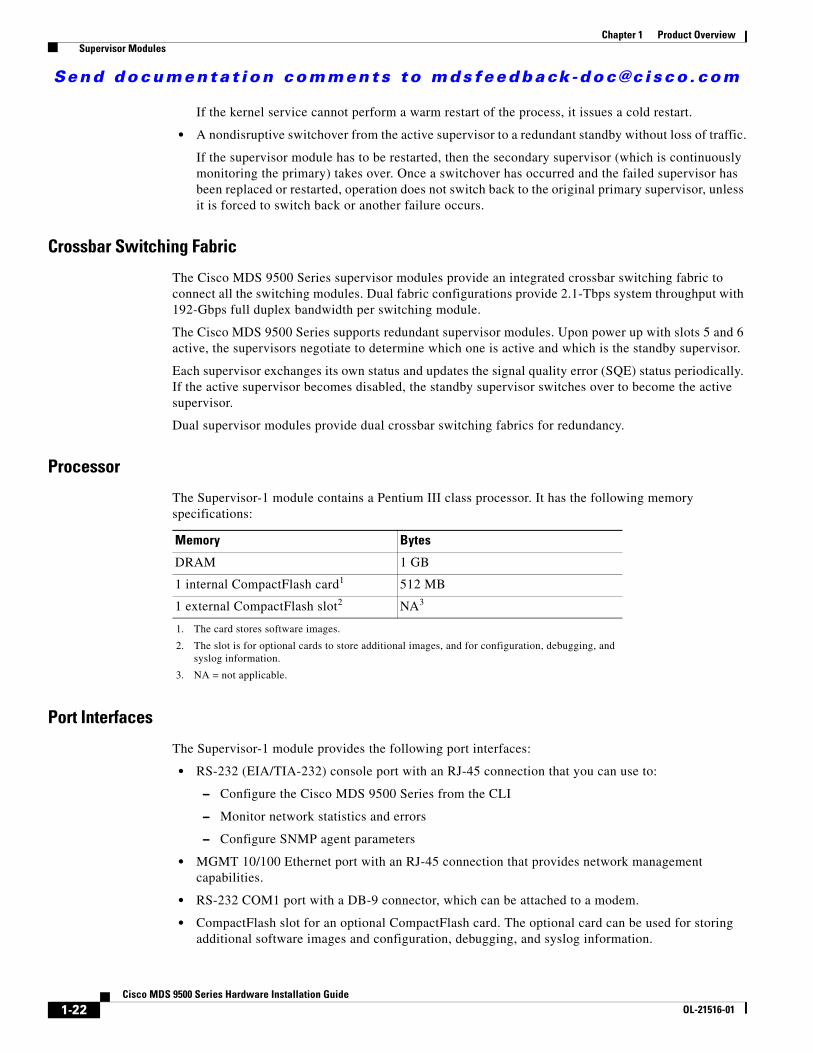
The Supervisor-1 module contains a Pentium III class processor. It has the following memory specifications:
Port Interfaces
The Supervisor-1 module provides the following port interfaces:
• RS-232 (EIA/TIA-232) console port with an RJ-45 connection that you can use to:
– Configure the Cisco MDS 9500 Series from the CLI
– Monitor network statistics and errors
– Configure SNMP agent parameters
• MGMT 10/100 Ethernet port with an RJ-45 connection that provides network management capabilities.
• RS-232 COM1 port with a DB-9 connector, which can be attached to a modem.
• CompactFlash slot for an optional CompactFlash card. The optional card can be used for storing additional software images and configuration, debugging, and syslog information.
Memory Bytes
DRAM 1 GB
1 internal CompactFlash card1
1. The card stores software images.
512 MB
1 external CompactFlash slot2
2. The slot is for optional cards to store additional images, and for configuration, debugging, and syslog information.
NA3
3. NA = not applicable.
1-22Cisco MDS 9500 Series Hardware Installation Guide
OL-21516-01

Send documenta t ion comments to mdsfeedback -doc@c i sco .com
Chapter 1 Product Overview Supervisor Modules
Caution Use only the CompactFlash devices that are certified for use with Cisco MDS switches and are formatted using Cisco MDS switches. Using CompactFlash devices that are uncertified or are formatted using other platforms may result in errors.
LEDs on the Supervisor-1 Module
The front panel on the Supervisor-1 module has the following LEDs:
• Status LED
• System LED
• Active LED
• Power Management LED
• MGMT 10/100 Ethernet port LEDs (at top of port):
– Link LED (on left)
– Activity LED (on right)
• CompactFlash LED for external CompactFlash card
The front panel on the supervisor module also includes a reset button (see Figure 1-15).
The LEDs on the Supervisor-1 module indicate the status of the Supervisor-1 module, power supplies, and fan module. Table 1-5 provides more information about these LEDs.
Figure 1-15 Supervisor-1 Module LEDs
1448
53
1-23Cisco MDS 9500 Series Hardware Installation Guide
OL-21516-01
Send documenta t ion comments to mdsfeedback -doc@c i sco .com
Chapter 1 Product Overview Supervisor Modules
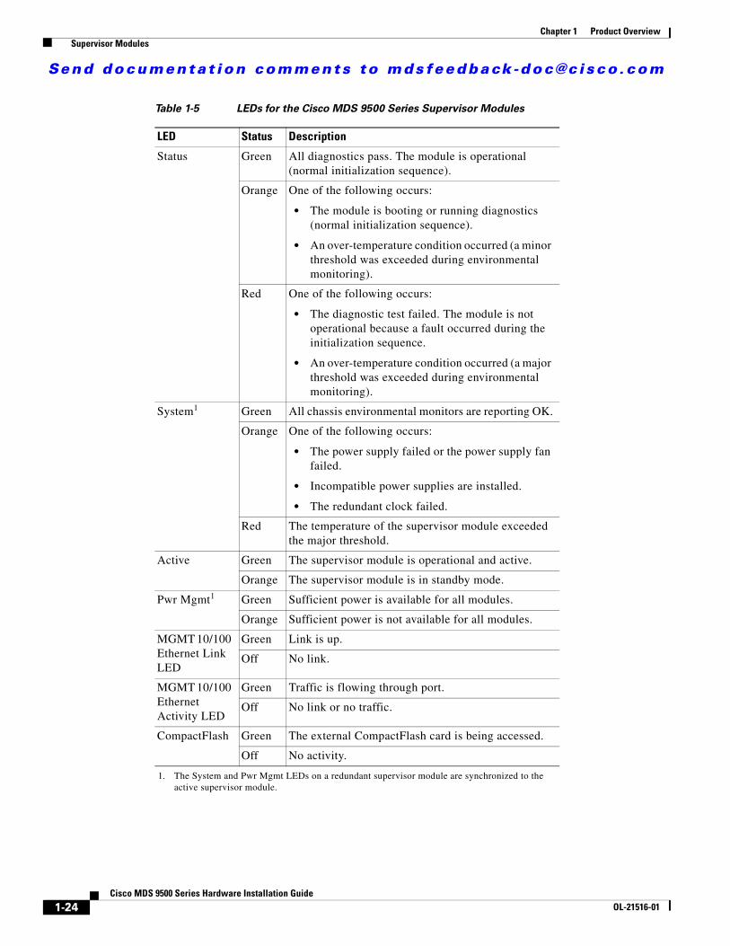
Table 1-5 LEDs for the Cisco MDS 9500 Series Supervisor Modules
LED Status Description
Status Green All diagnostics pass. The module is operational (normal initialization sequence).
Orange One of the following occurs:
• The module is booting or running diagnostics (normal initialization sequence).
• An over-temperature condition occurred (a minor threshold was exceeded during environmental monitoring).
Red One of the following occurs:
• The diagnostic test failed. The module is not operational because a fault occurred during the initialization sequence.
• An over-temperature condition occurred (a major threshold was exceeded during environmental monitoring).
System1
1. The System and Pwr Mgmt LEDs on a redundant supervisor module are synchronized to the active supervisor module.
Green All chassis environmental monitors are reporting OK.
Orange One of the following occurs:
• The power supply failed or the power supply fan failed.
• Incompatible power supplies are installed.
• The redundant clock failed.
Red The temperature of the supervisor module exceeded the major threshold.
Active Green The supervisor module is operational and active.
Orange The supervisor module is in standby mode.
Pwr Mgmt1 Green Sufficient power is available for all modules.
Orange Sufficient power is not available for all modules.
MGMT 10/100 Ethernet Link LED
Green Link is up.
Off No link.
MGMT 10/100 Ethernet Activity LED
Green Traffic is flowing through port.
Off No link or no traffic.
CompactFlash Green The external CompactFlash card is being accessed.
Off No activity.
1-24Cisco MDS 9500 Series Hardware Installation Guide
OL-21516-01

Send documenta t ion comments to mdsfeedback -doc@c i sco .com
Chapter 1 Product Overview Crossbar Modules
Crossbar ModulesThe Cisco MDS 9513 Director supports two external crossbar modules located at the rear of the chassis. Each Supervisor-2 module has an associated external crossbar module for redundancy. The Supervisor-2 module in slot 7 is associated with crossbar module 1 and Supervisor-2 in slot 8 is associated with crossbar module 2. Redundant crossbar modules act in an active-active method, where each switching module forwards traffic across both crossbar fabrics based on the intended destination. The traffic load is shared across both crossbar modules. Each crossbar fabric channel connects to a fabric interface ASIC on the switching modules through serial links on the midplane. Each Supervisor-2 processor also has a 20-Gbps (40-Gbps FDX) link to each crossbar fabric for participating in management and control protocols and for in-band diagnostics.
The LEDs on the crossbar modules indicate the status of the crossbar modules. Table 1-6 provides more information about these LEDs.
For information regarding migrating to Generation 3 modules, see the “Migrating to Generation 3 8-Gbps Fibre Channel Switching Modules” section on page A-1.
Figure 1-16 Crossbar Module LEDs
181335
1-25Cisco MDS 9500 Series Hardware Installation Guide
OL-21516-01

Send documenta t ion comments to mdsfeedback -doc@c i sco .com
Chapter 1 Product Overview Crossbar Modules
Table 1-6 LEDs for the Cisco MDS 9500 Crossbar Modules
LED Status Description
Status Green All diagnostics pass. The module is operational (normal initialization sequence).
Orange One of the following occurs:
• The module is booting or running diagnostics (normal initialization sequence).
• An over-temperature condition occurred (a minor threshold was exceeded during environmental monitoring).
Red One of the following occurs:
• The diagnostic test failed. The module is not operational because a fault occurred during the initialization sequence.
• An over-temperature condition occurred (a major threshold was exceeded during environmental monitoring).
1-26Cisco MDS 9500 Series Hardware Installation Guide
OL-21516-01

Send documenta t ion comments to mdsfeedback -doc@c i sco .com
Chapter 1 Product Overview Cisco MDS 9000 Series Module Compatibility
Cisco MDS 9000 Series Module CompatibilityTable 1-7 lists the hardware modules available and the chassis compatibility associated with them.
Table 1-7 MDS 9000 Modules and Platform Compatibility Matrix
Module 9513 9509 9506 9222i 9216A 9216i 9216
Supervisor-2 module X X X
Supervisor -1 module X X
16-port Storage Services module (SSN-16) X X X X
48-port 8-Gbps Fibre Channel switching module X X X
24-port 8-Gbps Fibre Channel switching module X X X
4/44-port 8-Gbps Host-Optimized Fibre Channel switching module
X X X X
48-port 4-Gbps Fibre Channel switching module X X X X X X
24-port 4-Gbps Fibre Channel switching module X X X X X X
12-port 4-Gbps Fibre Channel switching module X X X X X X
4-port 10-Gbps Fibre Channel switching module X X X X X X
32-port 1-Gbps/2-Gbps Fibre Channel switching module X X X X X X
16-port 1-Gbps/2-Gbps Fibre Channel switching module X X X X X X
8-port Gigabit Ethernet IP Storage Services module X X X X X X X
4-port Gigabit Ethernet IP Storage Services module X X X X X X
32-port 1-Gbps/2-Gbps Fibre Channel Storage Services Module (SSM)
X X X X X X X
32-port Fibre Channel Advanced Services Module (ASM) X X X X X
Caching Services Module (CSM) X X X X X
18-port Fibre Channel and 4-port Gigabit Ethernet IP Services (MSM-18/4) module
X X X X X X
14-port Fibre Channel/2-port Gigabit Ethernet Multiprotocol Services (MPS-14/2) module
X X X X X X
1-27Cisco MDS 9500 Series Hardware Installation Guide
OL-21516-01

Send documenta t ion comments to mdsfeedback -doc@c i sco .com
Chapter 1 Product Overview Port Index Availability
Port Index AvailabilityThe Cisco MDS 9500 Multilayer Directors are designed to operate with any combination of Cisco MDS 9000 modules. However, you should be aware of the maximum port availability your chassis can support. A port index is an internally assigned number that Cisco NX-OS uses to switch data packets within the director or fabric switch. When the maximum number of port indexes is reached in a chassis, any modules remaining or added to the chassis will not boot up. The number of physical ports on a Fibre Channel module is equal to its number of port indexes. However, for Gigabit Ethernet modules (IPS-8, IPS-4, MPS-14/2, MSM-18/4, and SSN-16), one physical port is equal to four port indexes (one port index for iSCSI and three port indexes for FC IP tunnels). Table 1-8 lists the physical ports and port indexes (virtual ports) available per Cisco MDS 9000 module.
Using any combination of modules that include a Generation 1 module or a Supervisor-1 module limits the port index availability to 252 on all Cisco MDS 9500 Series directors. Generation 1 modules also require contiguous port indexes where the system assigns a block of port index numbers contiguously starting from the first port index reserved for the slot that the module is inserted in (See Table 1-9). This means that while there may be enough port indexes available for a Generation 1 module, the module may not boot up because the available port indexes are not in a contiguous range or the contiguous block does not start at the first port index for a given slot.
Table 1-8 Port Index Allocation
Module Physical Ports Port Indexes Allocated
16-port Storage Services module (SSN-16) 16 64
48-port 8-Gbps Fibre Channel switching module 48 48
24-port 8-Gbps Fibre Channel switching module 24 24
4/44-port 8-Gbps Host-Optimized Fibre Channel switching module
48 48
48-port 4-Gbps Fibre Channel switching module 48 48
24-port 4-Gbps Fibre Channel switching module 24 24
12-port 4-Gbps Fibre Channel switching module 12 12
4-port 10-Gbps Fibre Channel switching module 4 4
16-port 2-Gbps Fibre Channel switching module 16 161
1. All Generation 1 modules reserve port indexes on fixed boundaries with Supervisor-1. See Table 1-9.
32-port 2-Gbps Fibre Channel switching module 32 321
8-port Gigabit Ethernet IP Storage Services module 8 321
4-port Gigabit Ethernet IP Storage Services module 4 32 (with Supervisor-1)16 (with Supervisor-2)
32-port 2-Gbps Fibre Channel Storage Services module (SSM)
32 321
18-port Fibre Channel and 4-port Gigabit Ethernet IP Multiservice module (MSM-18/4)
222
2. 18 Fibre Channel ports and four Gigabit Ethernet ports.
34
14-port Fibre Channel/2-port Gigabit Ethernet Multiprotocol Services (MPS-14/2) module
163
3. 14 Fibre Channel ports and two Gigabit Ethernet ports.
32 (with Supervisor-1)22 (with Supervisor-2)
1-28Cisco MDS 9500 Series Hardware Installation Guide
OL-21516-01

Send documenta t ion comments to mdsfeedback -doc@c i sco .com
Chapter 1 Product Overview Port Index Availability
Example 1-1 shows a scenario with a Supervisor-1 module, where a 48-port Generation 2 module borrowed port indexes from the first slot. Slot 1 still has 16 port indexes available, but the full 32 indexes are no longer available (28-31 are used by the module in slot 4). This means that no Generation 1 module except a 16-port Fibre Channel switching module can be inserted into slot 1 because some of the port indexes for the slot are already in use.
Example 1-1 Borrowing Port Indexes from Another Slot
switch# show port index-allocationModule index distribution:---------------------------------------------------+Slot | Allowed | Alloted indices info | | range* | Total | Index values |-------|---------|-------|-------------------------|1 | 0- 31| - | - |2 | 32- 63| 32 | 32-63 |3 | 64- 95| 48 | 64-95,224-239 |4 | 96- 127| 48 | 96-127, 240-252, 28-31 |7 | 128- 159| 32 | 128-159 |8 | 160- 191| 32 | 160-191 |9 | 192- 223| 32 | 192-223 |SU | 253-255 | 3 | 253-255 |*Allowed range applicable only for Generation-1 modules
Using any combination of modules that include a Generation 1 module and a Supervisor-2 module limits the port index availability to 252 on all Cisco MDS 9500 Series Directors. The Generation 1 modules can use any contiguous block of port indexes that start on the first port index reserved for any slot in the range 0-252. (See Table 1-9.)
Using any combination of only Generation 2 with a Supervisor-2 module allows a maximum of 528 (with an architectural limit of 1020) port indexes on all Cisco MDS 9500 Series Directors. Generation 2 modules do not need contiguous port indexes. Generation 2 modules use the available indexes in the slot that it is installed and then borrow available indexes from the supervisors. If the module requires more indexes, it starts borrowing available indexes from slot 1 of the chassis until it has the number of port indexes necessary.
Note Enter the purge module CLI command to free up reserved port indexes after you remove a module.
1-29Cisco MDS 9500 Series Hardware Installation Guide
OL-21516-01
Send documenta t ion comments to mdsfeedback -doc@c i sco .com
Chapter 1 Product Overview Port Index Availability
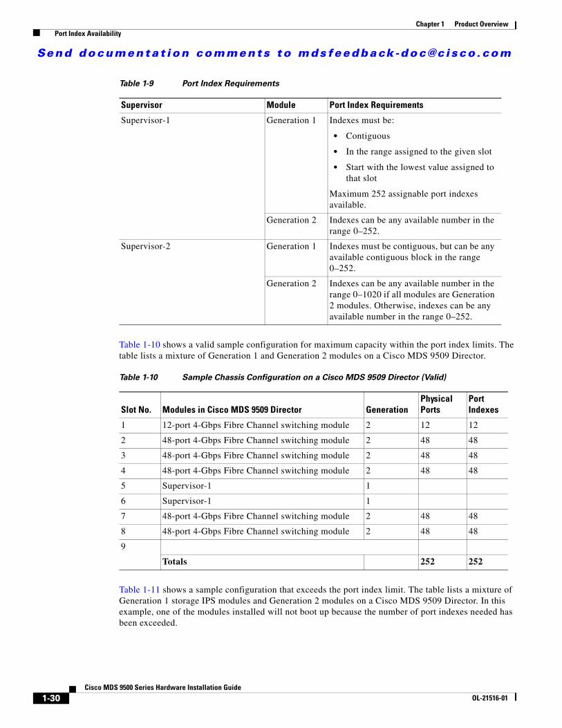
Table 1-10 shows a valid sample configuration for maximum capacity within the port index limits. The table lists a mixture of Generation 1 and Generation 2 modules on a Cisco MDS 9509 Director.
Table 1-11 shows a sample configuration that exceeds the port index limit. The table lists a mixture of Generation 1 storage IPS modules and Generation 2 modules on a Cisco MDS 9509 Director. In this example, one of the modules installed will not boot up because the number of port indexes needed has been exceeded.
Table 1-9 Port Index Requirements
Supervisor Module Port Index Requirements
Supervisor-1 Generation 1 Indexes must be:
• Contiguous
• In the range assigned to the given slot
• Start with the lowest value assigned to that slot
Maximum 252 assignable port indexes available.
Generation 2 Indexes can be any available number in the range 0–252.
Supervisor-2 Generation 1 Indexes must be contiguous, but can be any available contiguous block in the range 0–252.
Generation 2 Indexes can be any available number in the range 0–1020 if all modules are Generation 2 modules. Otherwise, indexes can be any available number in the range 0–252.
Table 1-10 Sample Chassis Configuration on a Cisco MDS 9509 Director (Valid)
Slot No. Modules in Cisco MDS 9509 Director GenerationPhysical Ports
Port Indexes
1 12-port 4-Gbps Fibre Channel switching module 2 12 12
2 48-port 4-Gbps Fibre Channel switching module 2 48 48
3 48-port 4-Gbps Fibre Channel switching module 2 48 48
4 48-port 4-Gbps Fibre Channel switching module 2 48 48
5 Supervisor-1 1
6 Supervisor-1 1
7 48-port 4-Gbps Fibre Channel switching module 2 48 48
8 48-port 4-Gbps Fibre Channel switching module 2 48 48
9
Totals 252 252
1-30Cisco MDS 9500 Series Hardware Installation Guide
OL-21516-01

Send documenta t ion comments to mdsfeedback -doc@c i sco .com
Chapter 1 Product Overview Port Index Availability
Using any combination of modules that include a Generation 1 module and a Supervisor-2 module limits the port index availability to 252 on all Cisco MDS 9500 Series Directors. But the Generation 1 modules can use any contiguous block of port indexes in the range 0–252 (See Table 1-9).
Using any combination of only Generation 2 with a Supervisor-2 module allows a maximum of 528 (with an architectural limit of 1020) port indexes on all Cisco MDS 9500 Series Directors. Generation 2 modules do not need contiguous port indexes. Generation 2 modules will use the available ports in the slot that it is installed and then borrow available ports from the supervisors, and then restart at slot 1 of the chassis until it has the number of port indexes necessary.
Table 1-12 shows a valid sample configuration for maximum capacity within the port index limits. The table only lists Generation 2 modules in a Cisco MDS 9513 Director.
Table 1-11 Maximum Chassis Configuration on a Cisco MDS 9509 Director (Exceeded)
Slot No. Modules in Cisco MDS 9509 Director GenerationPhysical Ports
Port Indexes
1 18-port Fibre Channel and 4-port Gigabit Ethernet IP Multiservice module (MSM-18/4)
2 22 34
2 14-port Fibre Channel/2-port Gigabit Ethernet Multiprotocol Services (MPS-14/2) module
1 16 22
3 8-port Gigabit Ethernet IP Storage Services module 1 8 32
4 4-port Gigabit Ethernet IP Storage Services module 1 4 16
5 48-port 4-Gbps Fibre Channel switching module 2 48 48
6 Supervisor-1 1
7 Supervisor-1 1
8 48-port 4-Gbps Fibre Channel switching module 2 48 48
9 48-port 4-Gbps Fibre Channel switching module 2 48 48
10 48-port 4-Gbps Fibre Channel switching module 2 48 48
Totals 240 296
Table 1-12 Maximum Chassis Configuration on a Cisco MDS 9513 Director (Valid)
Slot No. Modules in Cisco MDS 9513 Director GenerationPhysical Ports
Port Indexes
1 48-port 4-Gbps Fibre Channel switching module 2 48 48
2 48-port 4-Gbps Fibre Channel switching module 2 48 48
3 48-port 4-Gbps Fibre Channel switching module 2 48 48
4 48-port 4-Gbps Fibre Channel switching module 2 48 48
5 48-port 4-Gbps Fibre Channel switching module 2 48 48
6 48-port 4-Gbps Fibre Channel switching module 2 48 48
7 Supervisor-2 2
8 Supervisor-2 2
9 48-port 4-Gbps Fibre Channel switching module 2 48 48
10 48-port 4-Gbps Fibre Channel switching module 2 48 48
1-31Cisco MDS 9500 Series Hardware Installation Guide
OL-21516-01

Send documenta t ion comments to mdsfeedback -doc@c i sco .com
Chapter 1 Product Overview Switching Modules
Switching ModulesThe Cisco MDS 9500 Series supports the following hot-swappable Fibre Channel switching modules:
• Generation 3 modules
– 48-Port 8-Gbps Fibre Channel Switching Module
– 24-Port 8-Gbps Fibre Channel Switching Module
– 4/44-Port 8-Gbps Host-Optimized Fibre Channel Switching Module
• Generation 2 modules
– 48-Port 4-Gbps Fibre Channel Switching Module
– 24-Port 4-Gbps Fibre Channel Switching Module
– 12-Port 4-Gbps Fibre Channel Switching Module
– 4-Port 10-Gbps Fibre Channel Switching Module
• Generation 1 modules
– 32-Port 2-Gbps Fibre Channel Switching Module
– 16-Port 2-Gbps Fibre Channel Switching Module
The Cisco MDS 9500 Series supports up to eleven hot-swappable switching modules. By combining different switching modules in a single, modular chassis, you can design cost and performance optimized storage networks in a wide range of application environments.
The Fibre Channel switching modules provide system-wide power management and autonegotiation, which allows ports to negotiate for speed at the other end of the link. Each module has temperature sensors and an EEPROM that stores serial number and model number information.
The Fibre Channel port interfaces support hot-swappable Fibre Channel SFP and SFP+ transceivers, which can be short wavelength (SWL) or long wavelength (LWL). The port interfaces also support coarse wavelength-division multiplexing (CWDM) and dense wavelength-division multiplexing (DWDM) SFP transceivers, which can be used for extended long wavelength (ELWL) transmission or for coarse wavelength-division multiplexing (CWDM) and dense wavelength-division multiplexing (DWDM). See the “Supported Transceivers” section on page 1-57.
Note The internal bootflash installed on the modules are not field-replaceable units. Do not remove or replace internal bootflash on the modules. Modifying the factory-installed bootflash is not supported.
11 48-port 4-Gbps Fibre Channel switching module 2 48 48
12 48-port 4-Gbps Fibre Channel switching module 2 48 48
13 48-port 4-Gbps Fibre Channel switching module 2 48 48
Totals 528 528
Table 1-12 Maximum Chassis Configuration on a Cisco MDS 9513 Director (Valid) (continued)
Slot No. Modules in Cisco MDS 9513 Director GenerationPhysical Ports
Port Indexes
1-32Cisco MDS 9500 Series Hardware Installation Guide
OL-21516-01

Send documenta t ion comments to mdsfeedback -doc@c i sco .com
Chapter 1 Product Overview Switching Modules
48-Port 8-Gbps Fibre Channel Switching ModuleThe 48-Port 8-Gbps Fibre Channel switching module offers 48 autosensing 1-, 2-, 4- and 8-Gbps Fibre Channel ports and can be used in the Cisco MDS 9500 Series Switches. The 48-port switching module can be configured in one of two operational modes: shared bandwidth mode (default) and dedicated bandwidth mode.
Figure 1-17 shows a 48-port 8-Gbps Fibre Channel switching module. The front panel connectors support standard modular SFP and SFP+ transceivers and the speed detection is autosensing.
Figure 1-17 48-Port 8-Gbps Fibre Channel Switching Module
24-Port 8-Gbps Fibre Channel Switching ModuleThe 24-Port 8-Gbps Fibre Channel switching module offers 24 autosensing 1-, 2-, 4- and 8-Gbps Fibre Channel ports and can be used in the Cisco MDS 9500 Series Switches. The 24-port switching module can be configured in one of two operational modes: shared bandwidth mode (default) and dedicated bandwidth mode.
Figure 1-18 shows a 24-port 8-Gbps Fibre Channel switching module. The front panel connectors support standard modular SFP and SFP+ transceivers and the speed detection is autosensing.
Figure 1-18 24-Port 8-Gbps Fibre Channel Switching Module
4/44-Port 8-Gbps Host-Optimized Fibre Channel Switching ModuleThe 4/44-port 8-Gbps Host-Optimized Fibre Channel switching module offers 48 autosensing 1-, 2-, 4- and 8-Gbps Fibre Channel ports and can be used in any of the Cisco MDS 9500 Series chassis and in the Cisco MDS 9222i Switches. The 48-port switching module can be configured in one of two operational modes: shared bandwidth mode (default) and dedicated bandwidth mode.
Figure 1-19 shows a 4/44-port 8-Gbps Host-Optimized Fibre Channel switching module. The front panel connectors support standard modular SFP and SFP+ transceivers and the speed detection is autosensing.
1886
5518
8656
1-33Cisco MDS 9500 Series Hardware Installation Guide
OL-21516-01

Send documenta t ion comments to mdsfeedback -doc@c i sco .com
Chapter 1 Product Overview Switching Modules
Figure 1-19 4/44-Port 8-Gbps Host-Optimized Fibre Channel Switching Module
48-Port 4-Gbps Fibre Channel Switching ModuleThe 48-port 4-Gbps Fibre Channel switching module offers 48 autosensing 1-, 2-, and 4-Gbps Fibre Channel ports and can be used in any of the Cisco MDS 9500 Series chassis and in the Cisco MDS 9216i and 9216A Switches. The 48-port switching module can be configured in one of two operational modes: shared bandwidth mode (default) and dedicated bandwidth mode.
Figure 1-20 shows a 48-port 4-Gbps Fibre Channel switching module. The front panel connectors support standard modular SFP and the speed detection is autosensing.
Figure 1-20 48-Port 4-Gbps Fibre Channel Switching Module
Figure 1-21 shows the port numbering and LEDs on the 48-port 4-Gbps Fibre Channel switching module.
Figure 1-21 48-Port 4-Gbps Fibre Channel Switching Module LEDs
1886
5714
4474
1 Status LED 3 Fibre Channel ports
2 Link LEDs
1448
09
1
2 3
1-34Cisco MDS 9500 Series Hardware Installation Guide
OL-21516-01

Send documenta t ion comments to mdsfeedback -doc@c i sco .com
Chapter 1 Product Overview Switching Modules
24-Port 4-Gbps Fibre Channel Switching ModuleThe 24-port 4-Gbps Fibre Channel switching module offers 24 autosensing 1-, 2-, and 4-Gbps Fibre Channel ports and can be used in any of the Cisco MDS 9500 Series chassis and in the Cisco MDS 9216i and 9216A Switches. The 24-port switching module can be configured in one of two operational modes: shared bandwidth mode (default) and dedicated bandwidth mode.
Figure 1-22 shows a 24-port 4-Gbps Fibre Channel switching module. The front panel connectors support standard modular SFP and the speed detection is autosensing.
Figure 1-22 24-Port 4-Gbps Fibre Channel Switching Module
12-Port 4-Gbps Fibre Channel Switching ModuleThe 12-port 4-Gbps Fibre Channel switching module can be used in any of the Cisco MDS 9500 Series chassis and in the Cisco MDS 9216i and 9216A Switches. The 12-port 4-Gbps switching module is a full rate mode module providing 12 SPF-based Fibre Channel interfaces. Each interface is capable of supporting full line rate operation at 4-Gbps interface speed. The module delivers a sustained data rate of up to 4 Gbps in each direction, on all ports simultaneously, and up to 96 Gbps of continuous, aggregate bandwidth when attached to high-performance servers and storage subsystems.
Figure 1-23 shows a 12-port 4-Gbps Fibre Channel switching module. The front panel connectors support standard modular SFP and the speed detection is autosensing.
Figure 1-23 12-Port 4-Gbps Fibre Channel Switching Module
1 Status LED 3 Fibre Channel ports
2 Link LEDs 4 Port group
1444
71
2
34
1
1 Status LED 3 Link LEDs
2 Fibre Channel ports
1444
70
3
2
1
1-35Cisco MDS 9500 Series Hardware Installation Guide
OL-21516-01
Send documenta t ion comments to mdsfeedback -doc@c i sco .com
Chapter 1 Product Overview Switching Modules
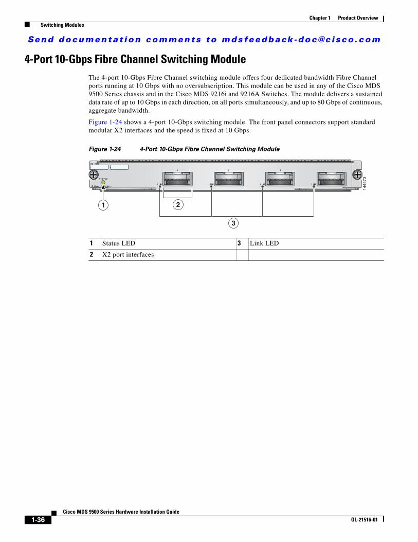
4-Port 10-Gbps Fibre Channel Switching ModuleThe 4-port 10-Gbps Fibre Channel switching module offers four dedicated bandwidth Fibre Channel ports running at 10 Gbps with no oversubscription. This module can be used in any of the Cisco MDS 9500 Series chassis and in the Cisco MDS 9216i and 9216A Switches. The module delivers a sustained data rate of up to 10 Gbps in each direction, on all ports simultaneously, and up to 80 Gbps of continuous, aggregate bandwidth.
Figure 1-24 shows a 4-port 10-Gbps switching module. The front panel connectors support standard modular X2 interfaces and the speed is fixed at 10 Gbps.
Figure 1-24 4-Port 10-Gbps Fibre Channel Switching Module
1 Status LED 3 Link LED
2 X2 port interfaces
1444
73
2
3
1
1-36Cisco MDS 9500 Series Hardware Installation Guide
OL-21516-01

Send documenta t ion comments to mdsfeedback -doc@c i sco .com
Chapter 1 Product Overview Switching Modules
LEDs on the Generation 2 Switching ModulesTable 1-13 describes the LEDs for the 48-port, 24-port, and 12-port 4-Gbps Fibre Channel switching modules and the 4-port 10-Gbps Fibre Channel switching module.
32-Port 2-Gbps Fibre Channel Switching ModuleThe 32-port 2-Gbps Fibre Channel switching module can be used to allocate bandwidth optimally. The module is organized into eight four-port groups. Only the first port in each four-port group can be an ISL. If the first port is an ISL, the other three ports in the group are disabled. The four ports within a port group share a single internal channel resulting in a subscription ratio of approximately 3.2 to 1. The 32-port 2-Gbps switching module provides more ports at a lower price per port. Figure 1-25 shows a 32-port switching module.
Table 1-13 LEDs for the Cisco MDS 9000 Family Generation 2 Fibre Channel Switching Modules
LED Status Description
Status Green All diagnostics pass. The module is operational (normal initialization sequence).
Orange One of the following occurs or occurred:
• The module is booting or running diagnostics (normal initialization sequence).
• The inlet air temperature of the system has exceeded the maximum system operating temperature limit (a minor environmental warning). To ensure maximum product life, you should immediately correct the environmental temperature and restore the system to normal operation.
Red One of the following occurs or occurred:
• The diagnostic test failed. The module is not operational because a fault occurred during the initialization sequence.
• The inlet air temperature of the system has exceeded the safe operating temperature limits of the card (a major environmental warning). The card has been shut down to prevent permanent damage.
Link Solid green Link is up.
Intermittent flashing green
Link is up (traffic on port).
Solid yellow Link is disabled by software.
Flashing yellow
A fault condition exists.
Off No link.
1-37Cisco MDS 9500 Series Hardware Installation Guide
OL-21516-01

Send documenta t ion comments to mdsfeedback -doc@c i sco .com
Chapter 1 Product Overview Switching Modules
Tip For a full 2-Gbps bandwidth between two hosts, connect one host to the first port group and the second host to the second port group.
Figure 1-25 Cisco MDS 9000 Family 32-Port 2-Gbps Switching Module
16-Port 2-Gbps Fibre Channel Switching ModuleThe 16-port 2-Gbps switching module supports a sustained data rate of up to 2-Gbps in each direction, on all ports simultaneously. The autosensing 2-Gbps ports of the 16-port Fibre Channel switching module deliver up to 64-Gbps of continuous, aggregate bandwidth when attached to high-performance servers and storage subsystems. Figure 1-26 shows a 16-port 2-Gbps switching module.
Figure 1-26 Cisco MDS 9000 Family 16-Port 2-Gbps Switching Module
1 Status LED 3 Link LEDs (under ports, on left) and Speed LEDs (under ports, on right)
2 1-Gbps/2-Gbps Fibre Channel port group
4 Asset tag
9167
3
2
1 43
17 20
4
DS-X9032
5
21 24
8 9
25 28
12 13
29 32
16
1 Status LED 3 Link LEDs (under ports, on left) and Speed LEDs (under ports, on right)
2 1-Gbps/2-Gbps Fibre Channel ports
4 Asset tag
9167
2
43
1 2 3 4 5 6 7 8 9 10 11 12 13 14 15 16
2
1
1-38Cisco MDS 9500 Series Hardware Installation Guide
OL-21516-01

Send documenta t ion comments to mdsfeedback -doc@c i sco .com
Chapter 1 Product Overview Switching Modules
Switching Module FeaturesEach switching module draws its power from the 42 V supplied on the backplane with local DC/DC power converters and regulators.
The control processor on the switching module provides power-on, offline, and online diagnostics. The control processor can be used for configuring devices on the switching module and to gather statistical data from each port.
The control processor can determine which slot it is plugged into, and it can monitor its DC/DC power source and temperature. The control processor signals the supervisor module and displays an alarm on its front panel when a problem is detected.
The front panel on the switching module provides basic status information, such as power-on, self-test running, self-test passed, alarm, and ready.
The binary image for the switching module is downloaded from the supervisor module. Prior to the image download, the control processor on the switching module runs from code stored on its local CompactFlash card.
Note Routine software downloads are not required.
The supervisor module can force a reset on the switching module and controls whether power is applied to the switching module.
If a single component or a set of components on the switching module fails, this does not disable other switching modules if that is the only failure in the system.
Each switching module has a hardware watchdog timer for detecting most component failures. This watchdog resets the card if is not serviced periodically.
1-39Cisco MDS 9500 Series Hardware Installation Guide
OL-21516-01

Send documenta t ion comments to mdsfeedback -doc@c i sco .com
Chapter 1 Product Overview Switching Modules
LEDs on the Generation 1 Switching ModuleTable 1-14 describes the LEDs for the 16-port and 32-port switching modules.
The Fibre Channel switching modules provide autoconfiguring Fibre Channel ports that support Fibre Channel speeds of 1.0625 Gbps and 2.125 Gbps. For more information about supported port types, see the Cisco MDS 9000 Family NX-OS Interfaces Configuration Guide.
Table 1-14 LEDs for the Cisco MDS 9000 Family Generation 1 Fibre Channel Switching Modules
LED Status Description
Status Green All diagnostics pass. The module is operational (normal initialization sequence).
Orange One of the following occurs or occurred:
• The module is booting or running diagnostics (normal initialization sequence).
• The inlet air temperature of the system has exceeded the maximum system operating temperature limit (a minor environmental warning). To ensure maximum product life, you should immediately correct the environmental temperature and restore the system to normal operation.
Red One of the following occurs or occurred:
• The diagnostic test failed. The module is not operational because a fault occurred during the initialization sequence.
• The inlet air temperature of the system has exceeded the safe operating temperature limits of the card (a major environmental warning). The card has been shut down to prevent permanent damage.
Speed On 2-Gbps mode.
Off 1-Gbps mode.
Steady flashing green
Link is up (beacon used to identify port).1
1. The flashing green light turns on automatically when an external loopback is detected that causes the interfaces to be isolated. The flashing green light overrides the beacon mode configuration. The state of the LED is restored to reflect the beacon mode configuration after the external loopback is removed.
Link Solid green Link is up.
Intermittent flashing green
Link is up (traffic on port).
Solid yellow Link is disabled by software.
Flashing yellow
A fault condition exists.
Off No link.
1-40Cisco MDS 9500 Series Hardware Installation Guide
OL-21516-01

Send documenta t ion comments to mdsfeedback -doc@c i sco .com
Chapter 1 Product Overview Services Modules
Services ModulesThe Cisco MDS 9500 Series supports the following hot-swappable Generation 1 services modules:
• 16-Port Storage Services Module, page 1-41
• 18/4-Port Multiservice Module, page 1-43
• 14/2-Port Multiprotocol Services Module, page 1-46
• IP Storage Services Modules, page 1-48
• 32-Port Fibre Channel Advanced Services Module, page 1-50
• 32-Port Fibre Channel Storage Services Module, page 1-52
• Caching Services Module, page 1-54
Note The internal bootflash installed on the modules are not field-replaceable units. Do not remove or replace internal bootflash on the modules. Modifying the factory installed bootflash is not supported.
16-Port Storage Services ModuleThe Cisco MDS 9000 Family 16-port Storage Services module (SSN-16) provides 16-Gigabit Ethernet IP services ports. The SSN-16 module provides 16 1-Gigabit Ethernet ports, and supports features such as I/O Accelerator, Storage Media Encryption and Fiber Channel over IP.
The SSN-16 module acts as a service blade for the storage applications. The module provides 16-Gigabit front panel ports for IPS and for the management of the ISAPI applications. For ISAPI, up to four Gigabit Ethernet ports are used for management of the application.
The ports are arranged in such a way that all the odd numbered ports (1, 3, 5, and so on till 15) are arranged in a single horizontal line and the even numbered ports (2, 4, 6, and so on till 16) are arranged below it, in another single horizontal line. That is, port 1 would be placed on the top left, port 2 would be placed on the bottom left, port 3 would be placed next to port 1, port 4 would be placed next to port 2, and so on.
The SSN-16 module provides transparent services to any port in a fabric and does not require additional SAN reconfiguration and rewiring. The module does not require the host or target to be directly attached and provides high availability with multimodule clustering and balancing.
By running four separate, concurrent applications on the SSN-16 module, it can provide the following functions:
• Provides better disaster recovery and continuity solutions for mission-critical applications.
• Minimizes the number of devices required, which improves the reliability.
• Consolidates the management with a single module, which provides end-to-end visibility.
• Provides optimized performance.
1-41Cisco MDS 9500 Series Hardware Installation Guide
OL-21516-01

Send documenta t ion comments to mdsfeedback -doc@c i sco .com
Chapter 1 Product Overview Services Modules
Figure 1-27
The SSN-16 module provides the following features:
• FCIP for remote SAN extension
– Simplifies data protection and business continuance strategies by enabling backup, remote replication, and other disaster-recovery services over WAN distances using open-standard FCIP tunneling.
– Optimizes utilization of WAN resources for backup and replication by enabling hardware-based compression, hardware-based encryption, FCIP write acceleration, and FCIP tape read and write acceleration.
– Preserves the Cisco MDS 9000 Family switch enhanced capabilities, including VSANs, advanced traffic management, and security, across remote connections.
• If you use engines for FCIP, then the mapping between the engines and the corresponding ports are:
– Engine 1 - Ports 1 to 4
– Engine 2 - Ports 5 to 8
– Engine 3 - Ports 9 to 12
– Engine 4 - Ports 13 to 16
• Integrated IP storage services in a high density form factor
The module supports 16-Gigabit Ethernet ports for FCIP. Individual ports can be configured with hot-swappable shortwave, longwave small form-factor pluggables (SFPs).
• Integrated hardware-based virtual SANs (VSANs) and Inter-VSAN Routing (IVR)
The module enables deployment of large-scale multisite and heterogeneous SAN topologies. Integration into port-level hardware allows any port within a system or fabric to be partitioned into any VSAN. Integrated hardware-based IVR provides line-rate routing between any ports within a system or fabric without the need for external routing appliances.
• Intelligent network services
The module uses VSAN technology for hardware-enforced, isolated environments within a single physical fabric, access control lists (ACLs) for hardware-based intelligent frame processing, and
2761
44
1 2
3
1 Status LED 3 Link LEDs
2 16-Gigabit Ethernet IP services ports
1-42Cisco MDS 9500 Series Hardware Installation Guide
OL-21516-01

Send documenta t ion comments to mdsfeedback -doc@c i sco .com
Chapter 1 Product Overview Services Modules
advanced traffic management features such as Fibre Channel congestion control and fabric-wide quality of service (QoS) to facilitate migration from SAN islands to enterprise-wide storage networks.
• Sophisticated diagnostics
The module provides intelligent diagnostics, protocol decoding, and network analysis tools as well as integrated Call Home capability for added reliability, faster problem resolution, and reduced service costs.
• Comprehensive network security framework
The module supports RADIUS and TACACS+, Fibre Channel Security Protocol (FC-SP), Secure File Transfer Protocol (SFTP), Secure Shell (SSH) Protocol, and Simple Network Management Protocol Version 3 (SNMPv3) implementing AES, VSANs, hardware-enforced zoning, ACLs, and per-VSAN role-based access control (RBAC). RBAC provides separate control over management functions and access on a per-VSAN basis, enabling separation of duties among administrators on the same physical switch. Gigabit Ethernet ports support IPsec authentication, data integrity, and hardware-assisted data encryption.
• IP version 6 (IPv6) support
The module supports IPv6 as mandated by the U.S. Department of Defense (DoD), Japan, and China. IPv6 support is provided for FCIP and management traffic routed in-band and out-of-band
18/4-Port Multiservice ModuleThe Cisco MDS 9000 Family 18/4-port Multiservice (MSM-18/4) module provides 18 autosensing 1-, 2-, and 4-Gbps Fibre Channel ports and four Gigabit Ethernet IP services ports. The MSM-18/4 module provides multiprotocol capabilities such as Fibre Channel, Fibre Channel over IP (FCIP), Small Computer System Interface over IP (iSCSI), IBM Fiber Connectivity (FICON), and FICON Control Unit Port (CUP) management.
The MSM-18/4 module provides18 4-Gbps Fibre Channel interfaces for high-performance SAN and mainframe connectivity and four Gigabit Ethernet ports for FCIP and iSCSI storage services. Individual ports can be configured with hot-swappable shortwave, longwave, extended-reach, coarse wavelength-division multiplexing (CWDM) or dense wavelength-division multiplexing (DWDM) Small Form-Factor Pluggables (SFPs) for connectivity up to 125 miles (200 km).
The MSM-18/4 module can minimize latency for disk and tape through FCIP write acceleration and FCIP tape write and read acceleration. The MSM-18/4 module provides up to 16 virtual Inter-Switch Link (ISL) connections on the four 1-Gigabit Ethernet ports through tunneling, and provides up to 4095 buffer-to-buffer credits that can be assigned to a single Fibre Channel port.
The MSM-18/4 supports hardware-based encryption and it is required to run the Storage Media Encryption (SME) which, is a part of the Cisco NX-OS. For more information on SME, see the Cisco MDS 9000 Family Storage Media Encryption Configuration Guide.
The MSM-18/4 supports SAN extension over IP and is compatible with current SAN extension products, such as MPS-14/2, 9216i, and IPS. The MSM-18/4 provides an integrated next generation 4-Gbps FC platform for SAN extension. The MSM-18/4 module supports Internet Protocol version 6 (IPv6) as mandated by the U.S. Department of Defense (DoD), Japan, and China. The IPv6 support is provided for FCIP, iSCSI, and management traffic routed in-band and out-of-band.
The MSM-18/4 provides intelligent diagnostics, protocol decoding, and network analysis tools with the integrated Call Home capability.
1-43Cisco MDS 9500 Series Hardware Installation Guide
OL-21516-01
Send documenta t ion comments to mdsfeedback -doc@c i sco .com
Chapter 1 Product Overview Services Modules
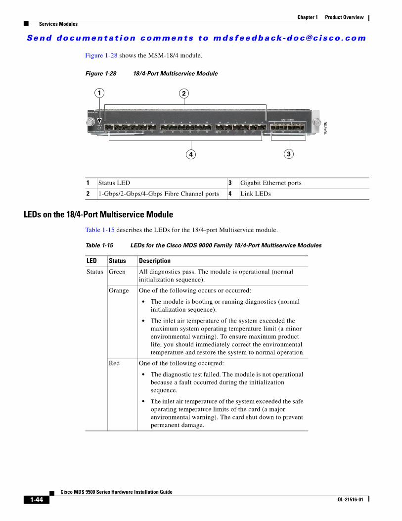
Figure 1-28 shows the MSM-18/4 module.
Figure 1-28 18/4-Port Multiservice Module
LEDs on the 18/4-Port Multiservice Module
Table 1-15 describes the LEDs for the 18/4-port Multiservice module.
1847
06
1 2
4 3
1 Status LED 3 Gigabit Ethernet ports
2 1-Gbps/2-Gbps/4-Gbps Fibre Channel ports 4 Link LEDs
Table 1-15 LEDs for the Cisco MDS 9000 Family 18/4-Port Multiservice Modules
LED Status Description
Status Green All diagnostics pass. The module is operational (normal initialization sequence).
Orange One of the following occurs or occurred:
• The module is booting or running diagnostics (normal initialization sequence).
• The inlet air temperature of the system exceeded the maximum system operating temperature limit (a minor environmental warning). To ensure maximum product life, you should immediately correct the environmental temperature and restore the system to normal operation.
Red One of the following occurred:
• The diagnostic test failed. The module is not operational because a fault occurred during the initialization sequence.
• The inlet air temperature of the system exceeded the safe operating temperature limits of the card (a major environmental warning). The card shut down to prevent permanent damage.
1-44Cisco MDS 9500 Series Hardware Installation Guide
OL-21516-01

Send documenta t ion comments to mdsfeedback -doc@c i sco .com
Chapter 1 Product Overview Services Modules
Link Solid green
Link is up.
Solid yellow
Link is disabled by software.
Flashing yellow
A fault condition exists.
Off No link.
Table 1-15 LEDs for the Cisco MDS 9000 Family 18/4-Port Multiservice Modules (continued)
LED Status Description
1-45Cisco MDS 9500 Series Hardware Installation Guide
OL-21516-01

Send documenta t ion comments to mdsfeedback -doc@c i sco .com
Chapter 1 Product Overview Services Modules
14/2-Port Multiprotocol Services ModuleThe 14/2-port Multiprotocol Services (MPS-14/2) module provides 14 2-Gbps Fibre Channel autosensing ports and two 1-Gigabit Ethernet ports for iSCSI and FCIP over Gigabit Ethernet. The MPS-14/2 module supports the intelligent features available on other modules, including VSANs, security, and traffic management.
The 14 2-Gbps autosensing Fibre Channel ports (labeled 1 through 14) are best used for applications requiring high bandwidth; for example, Inter-Switch Link (ISL) connections between switches and high-performance host or storage controllers. Each Fibre Channel port supports a sustained data rate of up to 2 Gbps in each direction.
The Cisco 9513 supports up to seven MPS-14/2 modules. The Cisco MDS 9509 supports up to seven MPS-14/2 modules. The Cisco MDS 9506 supports up to four MPS-14/2 modules. The two Gigabit Ethernet ports (labeled 1 and 2) provide 1-Gbps throughput for IP services, including iSCSI and FCIP over Gigabit Ethernet. The MPS-14/2 also supports hardware-based encryption and compression for these Gigabit Ethernet ports. This hardware-based encryption handles the computationally intensive IPsec feature for IP services.
The MPS-14/2 modules support FCIP compression to maximize the effective WAN bandwidth of SAN extension solutions. It achieves up to a 30 to 1 compression ratio, with typical ratios of 2 to 1 over a wide variety of data sources. With the addition of hardware-based compression, the MPS-14/2 module is able to provide optimal levels of compressed throughput for implementations across low-bandwidth to high-bandwidth links.
The Gigabit Ethernet ports on the MPS-14/2 module support the iSCSI protocol, the FCIP protocol, or both protocols simultaneously. For information about configuring the ports, see the Cisco MDS 9000 Family NX-OS Interfaces Configuration Guide.
The Fibre Channel port interfaces support hot-swappable Fibre Channel SFP transceivers, which can be short wavelength (SWL) for connectivity up to 1640 feet (500 meters), or long wavelength (LWL) for connectivity up to 6.2 miles (10 km). All Fibre Channel interfaces are autosensing 1-Gbps or 2-Gbps compatible. The Fibre Channel interfaces also support coarse wavelength-division multiplexing (CWDM) SFP transceivers, which can be used for extended long wavelength (ELWL) transmission or for CWDM. See the “Supported Transceivers” section on page 1-57.
Note Cisco MDS 9500 Series switches running Cisco MDS SAN-OS Release 2.x, 3.x, or NX-OS Release 4.1(1b) support the MPS-14/2 module.
1-46Cisco MDS 9500 Series Hardware Installation Guide
OL-21516-01

Send documenta t ion comments to mdsfeedback -doc@c i sco .com
Chapter 1 Product Overview Services Modules
Figure 1-29 shows an MPS-14/2 module.
Figure 1-29 Cisco MDS 9000 Family MPS-14/2 Module
LEDs on the MPS-14/2 Module
Table 1-16 describes the LEDs for the MPS-14/2 modules.
1 Status LED 4 Gigabit Ethernet ports
2 1-Gbps/2-Gbps Fibre Channel ports 5 Link LEDs
3 Link LEDs (under ports, on left) and Speed LEDs (under the ports, on the right)
6 Asset tag
—SPEED LINK—
LINK-
—SPEEDLINK—
STATUS
1 5 6 7 8 9
LINK— —SPEED
10 11 12 13 142 3 4
1 2
LINK-
GIGABIT E THERNET
1168
89
1 6
2 4
3 5
Table 1-16 LEDs for the Cisco MDS 9000 Family MPS-14/2 Modules
LED Status Description
Status Green All diagnostics pass. The module is operational (normal initialization sequence).
Orange One of the following occurs or occurred:
• The module is booting or running diagnostics (normal initialization sequence).
• The inlet air temperature of the system exceeded the maximum system operating temperature limit (a minor environmental warning). To ensure maximum product life, you should immediately correct the environmental temperature and restore the system to normal operation.
Red One of the following occurred:
• The diagnostic test failed. The module is not operational because a fault occurred during the initialization sequence.
• The inlet air temperature of the system exceeded the safe operating temperature limits of the card (a major environmental warning). The card shut down to prevent permanent damage.
Speed On 2-Gbps mode.
Off 1-Gbps mode.
1-47Cisco MDS 9500 Series Hardware Installation Guide
OL-21516-01

Send documenta t ion comments to mdsfeedback -doc@c i sco .com
Chapter 1 Product Overview Services Modules
IP Storage Services Modules The 4-port and 8-port IP Storage services (IPS-4 and IPS-8) modules provide four or eight 1-Gigabit Ethernet ports for iSCSI as well as FCIP over Gigabit Ethernet, and they support the intelligent features available on other modules, including VSANs, security, and traffic management.
The IPS module ports can be configured to support the iSCSI protocol, the FCIP protocol, or both protocols simultaneously. For information about configuring the ports, see the Cisco MDS 9000 Family NX-OS Interfaces Configuration Guide.
The Fibre Channel port interfaces support hot-swappable Gigabit Ethernet SFP transceivers, which can be short wavelength (SWL) for connectivity up to 1640 feet (500 meters), or long wavelength (LWL) for connectivity up to 6.2 miles (10 km). The port interfaces also support coarse wavelength-division multiplexing (CWDM) SFP transceivers, which can be used for extended long wavelength (ELWL) transmission or for CWDM. See the “Supported Transceivers” section on page 1-57.
Figure 1-30 shows an IPS-8 services module.
Figure 1-30 Cisco MDS 9000 Family IPS-8 Services Module
Link Solid green
Link is up.
Flashing green
Link is up (beacon used to identify port).
Solid yellow
Link is disabled by software.
Flashing yellow
A fault condition exists.
Off No link.
Table 1-16 LEDs for the Cisco MDS 9000 Family MPS-14/2 Modules (continued)
LED Status Description
1 Status LED 3 Link LEDs
2 Gigabit Ethernet ports 4 Asset tag
9169
4
2
1 43
1-48Cisco MDS 9500 Series Hardware Installation Guide
OL-21516-01

Send documenta t ion comments to mdsfeedback -doc@c i sco .com
Chapter 1 Product Overview Services Modules
Figure 1-31 shows the IPS-4 services module.
Figure 1-31 Cisco MDS 9000 Family IPS-4 Services Module
LEDs on IP Storage Services Modules
Table 1-17 describes the LEDs for the IPS services modules.
1 Status LED 3 Link LEDs
2 Gigabit Ethernet ports 4 Asset tag
1131
61
LINK LINK LINK LINK
1 2 3 4
1 43
2
Table 1-17 LEDs for the Cisco MDS 9000 Family IPS Module
LED Status Description
Status Green All diagnostics pass. The module is operational (normal initialization sequence).
Orange One of the following occurs or occurred:
• The module is booting or running diagnostics (normal initialization sequence).
• The inlet air temperature of the system exceeded the maximum system operating temperature limit (a minor environmental warning). To ensure maximum product life, you should immediately correct the environmental temperature and restore the system to normal operation.
Red One of the following occurred:
• The diagnostic test failed. The module is not operational because a fault occurred during the initialization sequence.
• The inlet air temperature of the system exceeded the safe operating temperature limits of the card (a major environmental warning). The card shut down to prevent permanent damage.
Link Solid green
Link is up.
Flashing green
Link is up (beacon used to identify port).
Solid yellow
Link is disabled by software.
Flashing yellow
A fault condition exists.
Off No link.
1-49Cisco MDS 9500 Series Hardware Installation Guide
OL-21516-01

Send documenta t ion comments to mdsfeedback -doc@c i sco .com
Chapter 1 Product Overview Services Modules
32-Port Fibre Channel Advanced Services ModuleThe Cisco MDS 9000 Family 32-port Fibre Channel Advanced Services Module (ASM) enables pooling of heterogeneous storage for increased storage utilization, simplified storage management, and reduced total cost of storage ownership. The ASM incorporates all the capabilities of the Cisco MDS 9000 DS-X9032 Fibre Channel switching module and also provides scalable, in-band storage virtualization services. The module makes it possible to allocate bandwidth optimally.
The Fibre Channel port interfaces support hot-swappable Fibre Channel SFP transceivers, which can be short wavelength (SWL) for connectivity up to 500 meters (1640 feet), or long wavelength (LWL) for connectivity up to 10 km (6.2 miles). All interfaces are autosensing 1-Gbps or 2-Gbps compatible. The port interfaces also support coarse wavelength-division multiplexing (CWDM) SFP transceivers, which can be used for extended long wavelength (ELWL) transmission or for CWDM. See the “Supported Transceivers” section on page 1-57.
Note Cisco MDS 9509 and 9506 Directors running Cisco MDS SAN-OS Release 1.2(2a) to Release 2.1(x) support the Fibre Channel ASM. The Cisco MDS 9513 Director does not support the ASM.
Figure 1-32 shows the Fibre Channel ASM.
Figure 1-32 Fibre Channel ASM
Each module draws power from the 42 V supplied on the backplane with local DC/DC power converters and regulators.
The control processor on the module provides power-on, offline, and online diagnostics. The control processor can be used to configure devices on the switching module and to gather statistical data from each port.
The control processor monitors the DC/DC power source and temperature. The control processor signals the supervisor module and displays an alarm on its front panel when a problem is detected.
The front panel on the services module provides basic status information, such as power-on, self-test running, self-test passed, alarm, and ready.
The binary image for the services module is downloaded from the supervisor module. Prior to the image download, the control processor on the switching module runs from code stored on its local CompactFlash card. The image for an ASM can be specified using the ASM-SFN boot variable. For details on how to specify the ASM-SFN boot variable, see the Cisco MDS 9000 Family NX-OS High Availability and Redundancy Configuration Guide.
1 Status LED 3 Link and Speed LEDs
2 1-Gbps/2-Gbps Fibre Channel port group
4 Asset tag94
298
2
1 43
17 20
4 5
21 24
8 9
25 28
12 13
29 32
16
DS-X9032
1-50Cisco MDS 9500 Series Hardware Installation Guide
OL-21516-01

Send documenta t ion comments to mdsfeedback -doc@c i sco .com
Chapter 1 Product Overview Services Modules
Note Software downloads are only necessary when a revision of the code is needed.
The supervisor module can force a reset on the services module and controls whether power is applied to the switching module.
If a single component or a set of components on the switching module fails, this failure does not disable another switching module if that is the only failure in the system.
Each ASM has a hardware watchdog timer to detect most component failures. The watchdog timer resets the card if it is not serviced periodically.
LEDs on the Fibre Channel Advanced Services Modules
Table 1-18 describes the LEDs for the Advanced Services module.
Table 1-18 LEDs for the Cisco MDS 9000 Family Fibre Channel ASMs
LED Status Description
Status Green All diagnostics pass and the module is operational (normal initialization sequence).
Orange One of the following occurs or occurred:
• The module is booting or running diagnostics (normal initialization sequence).
• The inlet air temperature of the system exceeded the maximum system operating temperature limit (a minor environmental warning). To ensure maximum product life, you should immediately correct the environmental temperature and restore the system to normal operation.
Red One of the following occurred:
• The diagnostic test failed. The module is not operational because a fault occurred during the initialization sequence.
• The inlet air temperature of the system exceeded the safe operating temperature limits of the card (a major environmental warning). The card shut down to prevent permanent damage.
Speed On 2-Gbps mode.
Off 1-Gbps mode.
Link Solid green Link is up.
Steady flashing green
Link is up (beacon used to identify port).
Intermittent flashing green
Link is up (traffic on port).
Solid yellow Link is disabled by software.
Flashing yellow A fault condition exists.
Off No link.
1-51Cisco MDS 9500 Series Hardware Installation Guide
OL-21516-01

Send documenta t ion comments to mdsfeedback -doc@c i sco .com
Chapter 1 Product Overview Services Modules
32-Port Fibre Channel Storage Services ModuleThe 32-port Fibre Channel Storage Services Module (SSM) for the Cisco MDS 9000 Family supports up to 32 Fibre Channel ports, provides distributed intelligent storage services, and supports future storage services.
Note Cisco MDS 9500 Series switches running Cisco MDS SAN-OS Release 2.x, 3.x, or NX-OS Release 4.1(1b) support the SSM.
The Fibre Channel ports support hot-swappable Fibre Channel SFP transceivers, which can be short wavelength (SWL) for connectivity up to 1640 ft (500 m), or long wavelength (LWL) for connectivity up to 6.2 miles (10 km). All interfaces are autosensing 1-Gbps/2-Gbps compatible. The ports also support coarse wavelength-division multiplexing (CWDM) SFP transceivers, which can be used for extended long wavelength (EWL) transmission or for CWDM. For more information about SFP transceivers, see the “Supported Transceivers” section on page 1-57.
Figure 1-33 shows the SSM.
Figure 1-33 Cisco MDS 9000 Family Storage Services Module
Each module draws power from the 42 V supplied on the backplane with local DC/DC power converters and regulators.
The control processor on the module provides power-on, offline, and online diagnostics. The control processor can be used to configure devices on the switching module and to gather statistical data from each port.
The control processor monitors the DC/DC power source and temperature. The control processor signals the SSM and displays an alarm on its front panel when it detects a problem.
The front panel of the SSM provides basic status information, such as power-on, self-test running, self-test passed, alarm, and ready.
The binary image for the SSM is downloaded from the supervisor module. Prior to the image download, the control processor on the services module runs from code stored on its local CompactFlash card. The image for an SSM can be specified using the SSI boot variable. For details on how to specify the SSI boot variable, see the Cisco MDS 9000 Family NX-OS Fundamentals Configuration Guide.
Note Software downloads are only necessary when a revision of the code is needed.
The SSM can force a reset and control whether or not power is applied to the switching module.
1 Status LED 3 Link and speed LEDs
2 1-Gbps/2-Gbps Fibre Channel port group 4 Asset tag12
0094
2
43
17 20
4 5
21 24
8 9
25 28
12 13
29 32
16
Storage Services Module
1
DS-X9032
1-52Cisco MDS 9500 Series Hardware Installation Guide
OL-21516-01

Send documenta t ion comments to mdsfeedback -doc@c i sco .com
Chapter 1 Product Overview Services Modules
If a single component or a set of components on the switching module fails, this failure will not disable another switching module if that is the only failure in the system.
For the detection of most component failures, each switching module has a hardware watchdog timer that resets the card if is not serviced periodically.
LEDs on the Storage Services Modules
Table 1-19 describes the LEDs for the Storage Services Modules.
Table 1-19 LEDs for the Cisco MDS 9000 Family Storage Services Modules
LED Status Description
Status Green All diagnostics pass. The module is operational (normal initialization sequence).
Orange One of the following occurs or occurred:
• The module is booting or running diagnostics (normal initialization sequence).
• The inlet air temperature of the system exceeded the maximum system operating temperature limit (a minor environmental warning). To assure maximum product life, you should immediately correct the environmental temperature and restore the system to normal operation.
Red One of the following occurred:
• The diagnostic test failed. The module is not operational because a fault occurred during the initialization sequence.
• The inlet air temperature of the system exceeded the safe operating temperature limits of the card (a major environmental warning). The card shut down to prevent permanent damage.
Speed On 2-Gbps mode.
Off 1-Gbps mode.
Link Solid green Link is healthy.
Steady flashing green
Link is healthy and beacon is enabled.
Intermittent flashing green
Link is up and traffic is flowing through port.
Solid yellow Link is disabled by software.
Flashing yellow A fault condition exists.
Off No link.
1-53Cisco MDS 9500 Series Hardware Installation Guide
OL-21516-01

Send documenta t ion comments to mdsfeedback -doc@c i sco .com
Chapter 1 Product Overview Services Modules
Caching Services ModuleThe Caching Services Module (CSM) provides virtualization services that allow the Cisco MDS 9000 Family switches to reallocate physical resources as virtual resources for increased efficiency. The CSM receives and sends data through the switch backplane. It has two disk drives, two internal batteries for backup in case of power failure, and no external ports.
CSMs must be implemented in pairs in the fabric to provide redundancy and backup. Only two or more CSMs in a fabric are supported. However, the CSMs do not have to be installed in the same switch.
The CSM may shut down because of the software, an external power failure, or the module separated from the backplane while it still had power. The CSM automatically backs up the data in memory to the disk drives and then shuts down. The CSM batteries provide adequate power to back up data without external power.
Note The Cisco MDS 9513 does not support the CSM.
Figure 1-34 shows the CSM.
Figure 1-34 CSM
Figure 1-35 shows the location of the disk drives and batteries on the CSM.
Caution The batteries are shipped fully charged and should be handled with caution accordingly.
1 Status LED 5 Disk 1 Status LED
2 Battery LED 6 Node 2 LEDs
3 Node 1 LEDs 7 Node 2 Status LED
4 Node 1 Status LED 8 Disk 2 Status LED
9162
6STATUS
DS-X9560-SMXX
BATTERY STATUS
NODE 1 NODE 2
DISK STATUS DISK
Cashing Services Module
3 6
8521 4 7
1-54Cisco MDS 9500 Series Hardware Installation Guide
OL-21516-01

Send documenta t ion comments to mdsfeedback -doc@c i sco .com
Chapter 1 Product Overview Services Modules
Figure 1-35 CSM, Internal View
See the “Installing a Switching or Services Module, Including Caching Services Modules” section on page 2-45 for information about installing the CSM and maintaining the CSM batteries.
1 Disk drive 2 3 Battery 2
2 Disk drive 1 4 Battery 1
9403
8
1
34
2
1-55Cisco MDS 9500 Series Hardware Installation Guide
OL-21516-01

Send documenta t ion comments to mdsfeedback -doc@c i sco .com
Chapter 1 Product Overview Services Modules
LEDs on the Caching Services Module
Table 1-20 describes the LEDs for the CSM.
Table 1-20 LEDs for the Cisco MDS 9000 Family CSM
LED Status Description
Status Green All diagnostics pass, and the module is operational (normal initialization sequence).
Orange One of the following occurs or occurred:
• The module is booting or running diagnostics (normal initialization sequence).
• The inlet air temperature of the system exceeded the maximum system operating temperature limit (a minor environmental warning). To ensure maximum product life, you should immediately correct the environmental temperature and restore the system to normal operation.
Red One of the following occurred:
• The diagnostic test failed. The module is not operational because a fault occurred during the initialization sequence.
• The inlet air temperature of the system exceeded the safe operating temperature limits of the card (a major environmental warning). The card shut down to prevent permanent damage.
Node Green Node is fully operational.
Flashing green Node is not yet part of a cluster.
Orange The module is booting or node is administratively down.
Flashing orange Node is in service mode.
Red Node failure.
Off Node does not have power.
Battery Green Battery has sufficient charge to dump cache.
Flashing green Battery is charging and has sufficient charge to dump cache. Battery conditioning in progress.
Flashing orange Battery is charging but has insufficient charge to dump cache.
Red Battery failure or battery is charged to the extent possible but in-sufficient to dump cache; replace CSM.
Off Battery does not have power and is not charged.
Disk Solid green Disk is operational.
Flashing orange Dumping cache to disk.
Flashing green Restoring cache from disk.
Red Disk failure.
Off Disk does not have power.
1-56Cisco MDS 9500 Series Hardware Installation Guide
OL-21516-01

Send documenta t ion comments to mdsfeedback -doc@c i sco .com
Chapter 1 Product Overview Supported Transceivers
Supported TransceiversThe following types of transceivers are available from Cisco and are supported on the Cisco MDS 9500 Series:
• X2 transceivers
• Fibre Channel SFP and SFP+ transceivers, in either SWL or LWL
• Combination Fibre Channel/Gigabit Ethernet SFP transceivers, in either SWL or LWL
• Combination Fibre Channel/Gigabit Ethernet CWDM SFP transceivers, which can be used for ELWL transmission or for CWDM
• Gigabit Ethernet SFP transceiver, 1-Gbps copper
• Fibre Channel DWDM SFP transceiver, which can be used for ELWL transmission or for DWDM
Note Switches running Cisco MDS SAN-OS Release 1.x, 2.x, 3.x, or NX-OS Release 4.1(1b) support combination Fibre Channel/Gigabit Ethernet SFP transceivers.
The transceivers are field-replaceable and hot-swappable. You can use any combination of SFP transceivers that are supported by the switch. The only restrictions are that SWL transceivers must be paired with SWL transceivers, and LWL transceivers with LWL transceivers, and the cable must not exceed the stipulated cable length for reliable communications.
For more information about the X2 transceiver, see the “X2 Transceiver Specifications” section on page C-19.
For more information about a specific Cisco SFP transceiver, see the “SFP and SFP+ Transceiver Specifications” section on page C-22. SFP transceivers can be ordered separately or with the Cisco MDS 9500 Series.
Note Use only Cisco transceivers in the Cisco MDS 9500 Series. Each Cisco transceiver is encoded with model information that enables the switch to verify that the transceiver meets the requirements for the switch.
X2 TransceiversThe X2 transceiver is a small form-factor transceiver optimized for 10-Gbps applications and uses an SC connector. The X2 transceiver is ideally suited for Ethernet, Fibre Channel and telecom switches, and standard (PCI) peripheral component interconnect based server and storage connections. The X2 provides robust thermal performance and electromagnetic shielding.
For more information about X2 transceiver specifications, see the “X2 Transceiver Specifications” section on page C-19.
1-57Cisco MDS 9500 Series Hardware Installation Guide
OL-21516-01

Send documenta t ion comments to mdsfeedback -doc@c i sco .com
Chapter 1 Product Overview Supported Transceivers
Fibre Channel SFP TransceiversCisco Fibre Channel SFP transceivers are available in SWL or LWL versions. Both of these versions are 1-Gbps/2-Gbps/4-Gbps capable. Cisco Fibre Channel SFP+ transceivers are available in SWL or LWL versions. Both of these versions are 2-Gbps/4-Gbps/8-Gbps capable.
Cisco Fibre Channel SFP transceivers have LC connectors and comply with 1-Gbps/2-Gbps/4-Gbps Fibre Channel standards as defined in FC-PI 10.0 2. Cisco Fibre Channel SFP+ transceivers have LC connectors and comply with 2-Gbps/4-Gbps/8-Gbps Fibre Channel standards as defined in FC-PI-4.
For more information about Fibre Channel SFP and SFP+ transceiver specifications, see the “SFP and SFP+ Transceiver Specifications” section on page C-22.
Combination Fibre Channel/Gigabit Ethernet SFP TransceiversThe combination Fibre Channel/Gigabit Ethernet SFP transceivers from Cisco Systems are available in SWL or LWL versions. Both of these versions are 1-Gbps/2-Gbps capable.
The combination SFP transceivers from Cisco Systems have LC connectors and comply with 1-Gbps/2-Gbps Fibre Channel as defined in FC-PI 10.0 2 and Gigabit Ethernet as defined in IEEE 802.3z.
For more information about Fibre Channel/Gigabit Ethernet SFP transceiver specifications, see the “SFP and SFP+ Transceiver Specifications” section on page C-22.
CWDM Combination Fibre Channel/Gigabit Ethernet SFP TransceiversThe Cisco CWDM SFP transceivers have LC connectors and support Gigabit Ethernet and 1-Gbps/2-Gbps Fibre Channel. They match the wavelength plan of Cisco CWDM GBICs and Cisco CWDM optical add/drop multiplexers (OADMs). Cisco 4-Gbps CWDM SFP transceivers are also available.
CWDM SFP transceivers are used in the following ways:
• CWDM transmission can send and receive up to eight laser wavelengths carrying different signals simultaneously on the same optical fiber using an OADM.
• ELWL signals can transmit over longer distances than LWL SFP transceivers.
There are eight different “colors” of CWDM SFP transceivers, one for each fixed wavelength. The fiber-optic cables from the CWDM SFP transceivers must be connected to an OADM. The OADM combines the wavelengths of the different outgoing signals into one composite send signal. The OADM also separates the received transmissions into the different wavelengths and sends them to the corresponding CWDM SFP transceiver.
For more information about CWDM SFP transceiver specifications, see the “SFP and SFP+ Transceiver Specifications” section on page C-22.
Gigabit Ethernet SFP TransceiversThe 4-port and 8-port IP Storage Services (IPS-4 and IPS-8) modules provide four or eight 1-Gigabit Ethernet ports that support Gigabit Ethernet SFP transceivers. The Gigabit Ethernet SFP transceivers have RJ-45 connectors and support Gigabit Ethernet (1-Gbps).
1-58Cisco MDS 9500 Series Hardware Installation Guide
OL-21516-01

Send documenta t ion comments to mdsfeedback -doc@c i sco .com
Chapter 1 Product Overview Supported Transceivers
For more information about Gigabit Ethernet SFP transceiver specifications, see the “SFP and SFP+ Transceiver Specifications” section on page C-22.
DWDM Fibre Channel SFP TransceiversThe Cisco DWDM SFP transceivers have LC connectors and support 1-Gbps and 2-Gbps Fibre Channel. The DWDM SFP transceivers match the International Telecommunications Union (ITU) 100-Ghz wavelength grid and the wavelength plan of Cisco 100-Ghz ONS product family.
DWDM SFP transceivers are used in the following ways:
• DWDM transmission can send and receive up to 32 laser wavelengths carrying different signals simultaneously on the same optical fiber using an optical filter.
• ELWL signals can transmit over longer distances than LWL SFP transceivers.
For more information about Gigabit Ethernet SFP transceiver specifications, see the “SFP and SFP+ Transceiver Specifications” section on page C-22.
1-59Cisco MDS 9500 Series Hardware Installation Guide
OL-21516-01

Send documenta t ion comments to mdsfeedback -doc@c i sco .com
Chapter 1 Product Overview Supported Transceivers
1-60Cisco MDS 9500 Series Hardware Installation Guide
OL-21516-01