overhead welding - philips bound... · that he can easily see the are and the pool ... in overhead...
TRANSCRIPT

I '
.JANUARY 1939
OVERHEAD WELDING
by J. SACK. 621.791.052
In this article a study is made of the forces acting during the transfer of weld metal fromthe welding rod to the piece of work in overhead welding. In this case the transfer ofwelding material is opposed by the weight of the drops, the kinetic pressure of the electronsin the arc and the electrodynamic forces on the charged drops due to the convergenceof the current lines of force at the crater. On the other hand the transfer is promoted bycapillary forces, electrodynamic forces due to the constriction of the liquid metal as thedrops leave the rod and explosive forces. From an estimation of these forces it is clearthat overhead welding is possible, as experience has in any case proved.
Introduetion
In arc welding use is made of welding rods whichare melted by the heat developed by an electricare between welding rod and piece of work. Weldingis usually done in such a position that the piece ofwork is below the welding rod, this is calledhorizontal welding. But it is som etirues neces-sary to carry out the welding operation from below,on the under side of the object to be welded. Theoperator must of course stand in such a positionthat he can easily see the are and the pool (thearea of molten metal on the article baingweldod].The work is then above his head, and the processis called overhead welding. Experience hasshown that this work can easily be performed withsuitable welding rods such as the type PH 50.lt is known that the metal is transferred from the
welding rod to the weld in the form of larger orsmaller drops 1), which, in the case of overheadwelding, means that the force of gravity is overcome.In overhead welding it is clear that there are other
1) J. Sack, Philips techno Rev. 2, 129, 1937.
forces besides that of gravity acting on the drops,and the question naturally arises as to the natureof these forces. The explanations which have beenproposed are vague or inadequate. Only with thehelp of X-ray cinematography 2) have we beensuccessful in obtaining a clear picture of whatoccurs in overhead welding.
A survey and an estimation of the intensity ofthe forces which act during the formation andtransfer of a drop are give'n below, Some of th eseforces oppose the transfer of drops and will becalled opposing forces. They must he overcomeby the forces which we shall call the propellingforces.
Opposing forces
Force of gravity
The weight of the drops can be determined bymoving the rod in such a way that the drops fallseparately and can be weighed. For the sake of
2) J. Sack, Philips techno Rev. 1, 26, 1936.
9
10 PHILIPS TECHNICAL REVIEW Vol. 3, No. 1
simplicity this is done in horizontal welding.Separate drops ate obtained by moving the weld-
ing rod sufficiently rapidly over the work (a flatplate for example) 2). If a welding rod with an iron.eore is used - and we shall deal only. with thatkind in this article - and a plate not of iron butof copper, the drops do not stiek to the plate, but'can' be removed and weighêd. .
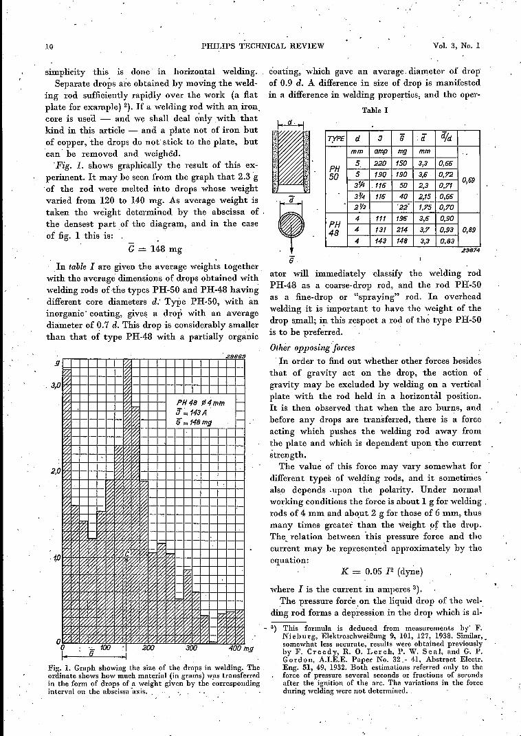
'Fig. 1. shows graphically the result of this ex-periment. It may be seen from the graph that 2.3 g'of the rod were melted into drops whose weightvaried from 120 to 140 mg. As average weight istaken the weight determined by the abscissa of 'the densest part of the diagram, and in the caseof fig. 1 this is:
G == 148 mg
In table 1 are given the average weights togetherwith the average dimensions of drops obtained withwelding rods of -the types PH-50 and PH-48 havingdifferent core diameters d: Type PH-50, with aninorganic' coating, gives a drop with an averagediameter of 0.7 d. This drop is considerably smallerthan that of type PH-48 with a partially organic
, 29,9B~
s I'l.:~ ~
3,0 ~ ~f2 ~~ ~
PH48 ~4mm i-1% f%::1:7:~ ~ ~ 'ti= 143A i-
~ ~ ~ '6= 148mg i-
f%: ~ ~I'l.: ~f%::I%: ~ 1000. . ~ 0.1%:
2,O~~ ~~~ ~~
r:Z ~ 0:~ ~ ~~ 0:~ ~ ~ ~I'l:: ~ 0- I'l::0- I'l::~ I'l.: In-0- I%::0.I'l::~~ ~ ........ ~ ~ ~ ~ ~ I'l::I%: 0. I%:: ~ l%i ~ ~ I'l::~0. ~ 0- 0- ~ 0 I'l;I%:~~ 0. I%:: 0- I%:: 0 ~ ~ 0. f'l:: I?:;0. ~ ~ I%:: 0- ~l/:: I%:~
, 't" ~ ~ 10~ 100 ~ 0: f'l::l/:: ~ f%:~ ~ ~ 10~ ~ ~ ~f'l::~ ~ ~ ~ P7f'l::~ ~ 10~ ~Ii% ~ ~ ~ ~ f%: f%::~ ~ 10~ ~ 0-1'l:: I'l;~ I«: ~ ~ Ii%f'l::~ 'l:100::~~ ~ 'l:~ ~ ~ I'l;~~ ~ ~ ~ 10~v.% '«~ 0.~ ~ I'l:: I/:; 'l:'l:~ ~ ~ ~ 10~ ~ ~ f%: ~ ~ ~ 0. ~ ....... 177 ~ ~~ ~ ~ 10 ~ 00. '«~0~ ~ ~ ~ ~ 10 ~ [%:::~0. ~ 0::~ I/:; I'l,:~ ~ f'l::~ ~ I/:;~ [%::~ ~0 ~ ~ 10
0~~~10~00.~~~~'l:f%::10f'l::~1'l,: 0. ~ 10o : '';_ 100 ~I 200 300 400
6I· -IFig. 1. Graph showing the size of the drops in welding. Theordinate shows how mnch material (in grams) was transferredin the form of drops of a weight given by the correspondinginterval on the abscissa -axis.
éoating, which gave an average, diameter of dropof 0.9 d. A difference in size of drop is manifestedin a difference in welding properties, and the oper-
Table I
TYPE d ::J G ([ did
mm amp mg mm
PH 5 220 150 3,3 0,66
50 5 190 190 3,6 0,72
3~ .116 50 2,3 0,710,69
3~4 116 40 2,15 0,662V2 '22' 1,75 0,70
PH 4 111 196 3,6 0,90
48 4 131 214 3,7 0,93 0,89
4 143 148 3,3 0,83.zSB74
"6ator will immediately classify the wélding rodPH-48 as a coarse-drop rod, and the rod PH-50as a fine-drop or "spraying" rod. In overheadwelding it is important to have the weight of thedrop small; in this respect a rod of thé type PH-50is to be preferred. ' ,
Othër opposing forcesIn order to find out whether other forces besides
that of .gravity act on the drop, the action ofgravity may be excluded by welding on a verticalplate with the rod held in a horizontàl position.It is then observed that when the are burns, andbefore any drops are transferred, there is a forceacting which pushes the welding rod away fromthe plate and which is dependent upon the currentstrength.The value of this force may vary somewhat for
different types of welding rods, and it sometimesalso depends ,upon the polarity. Under normal'working conditions the force is about 1g for :welding .rods of 4 mm and about 2 g for those of 6 mm, thusmany times greater than the weight fJf the drop.The. relation between this pressure force and thecurrent may be represented approximately by theequation:
K = 0.05 12 (dyne)
where 1 is the current in amperes 3).The pressure force on the liquid drop of the wel-
ding rod forms a depression in the drop which is al-
mg
This formula is deduced from measurements by' F.Nieburg, Elektroschweiûung 9, 101, 127, 1938. Similarv ,somewhat less accurate, results were obtained previouslyby F. Creedy, R. O. Lerch, P. W. Seal, and G. P.Gordon, A.LE.E. Paper No. 32 - 4.1, Abstract Electr.Eng. 51, 49, 1932. Both estimations referred only to theforce of pressure several seconds or fractions of secondsafter the ignition of the are, The variations in the forceduring welding were not determined.

11 OVERHEAD WELDING 11
ways observed in X-ray cinematographic pictures(see for instance .fig. 2c).
c)
tb)
a)
29877
Fig. 2. X-ray cinematographic film (50 pictures per sec) of.the drop in overhead welding. The stretchedout form of thedrop in picture a and the depression on the top of the drop in cshould be noticed especially.
The present state of knowledge about the weldingare is inadequate to give perfect insight into thecauses of this opposing force. Physicists are mostinterested in what happens at the cathode of thedischarge, and the pressure has been theoreticallyexamined at the cathode 4). From the calculationit is found that the repelling force may be mainlyascribed to the hombardment of the cathode bypositive ions. If n is the number of ions (or electrons)per unit volume of the column of the are, the pres-sure of the ions on the cathode is
p = nk T, ..
where T is the absolute temperature of the elec-trons and k is Boltzmann 's constant.
In the welding are the temperature of the elec-trons as well as that of the ions is about 6000 oK,while the concentratien of electrons may be estim-ated at It = 2 . 1016 electrons per cubic centi-metre 5). Using these values in equation (1) apressure is obtained of p = 17000 dynes/sq.cm.
The size ofthe cathode spot on which the pressure
4) L. Tonks, Phys. Rev. 46, 278, 1934-,5) This estimation is based on the assumption that there
exists an ionization equilibrium between the electrons andthe iron vapour in the are, The degree of ionization a ofthe iron can be calculated by means of Sa h a's formulawhich is as follows:
a2p 5000 V19 l-u.2 = -~r + 2.1 19 T - 6.5.
P is here the pressure of the iron vapour, in our case 1atmosphere. Vi is the ionization potentialof the iron atomsand is equal to 7.8 volts. The degree of ionization a is smallcompared with unity. If the relation between the gasdensity and the temperature is taken into account, the
acts, follows from the current density at the ca-thode, which is about 7 000 A/sq.cm. With a CUl'7
rent of 180 A the area of the cathode spot isf = 180/7000 = 0.026 sq.cm, and the force onthe cathode thus becomes:
k = pf = 17 000 . 0.026 = 440 dynes = 0.435 g,
while the observations under these circumstancesgive an average value more than twice as great.Finally the electrodynamic forces must be taken
into account, which are due to the action of theelectra-magnetic field on the lines of force of thecurrent. The electric current through a conductormay be considered to be flowing through tubes ofcurrent which attract each other since the directionof the current is the same in all the tubes.If the top of a welding rod is examined in the
initial state, i.e. before any drop has been formed-(see jig. 3), it will be seen that the current lines
29870
Fig. 3. Current lines of force at the top of the welding rod. Thearrows indicate the direction of the electrodynamic forces.The convergence of the current lines gives rise to a resultautdownward force.
(1) converge at the crater. The electrodynamic forces,which are also represented in fig. 3, have a down-ward resultant due to the curve in the lines of forceof the current. The value of the resultant force canbc calculated (see p. 14) and we find:
[2 O2k = - In - dyne,
200 Ol. (2)
where Ol is the area of the crater and 02. the crosssection area of the iron core of the welding rod, while.I must be in amperes. For I = 180 A and a negat.ivecrater (0.026 sq.cm) one finds k = 255 dynes =
0.26 g.If the crater is positive then its area is so large
that one may hardly speak of a convergence of thelines of force. In this case therefore the electro-dynamic force may be neglected.
following is found for the number of electrons per cc:
4_ :_S_<II! V11 = '1.3 . 10'8 IT· 10 T '
and for t = 6000 OK and Vi = 7.8 volts it follows thatn = 2 . 1016•

12 PHILlPS TECHNICAL REVIEW Vol. 4, No. 1
Propelling forcesWe noted above that the resultant opposing force
at the beginning of drop formation is many timesgreater than the weight of the drops. The propellingforces must be able to overcome these forces, sinceotherwise the transfer of drops would be impossiblein overhead welding.
The most important propelling forces are thesurface tension, the electrodynamic and explosiveforces.
Su~face tensionCapillary force or surface tension already plays
an important part during the formation ofthe drops.It is due to this force that the liquid metal remainson the top of the welding rod and does not run alongthe rod and drip off. Surface tension also keepsthe molten metal in the inverted pool.
When the are is kept short enough the drop onthe welding rod can make contact with the pool,.which can then absorb part of the drop of liquidmetal. Figs. 4a, b, c and the X-ray photographs
a b C2987/
Fig. 4. Transfer of liquid material from the welding rod tothe piece of wo:k.
fig· 5 show the three stages of this process:a) The molten metal of the piece of work makes
contact with that on the welding rod.b) The drop of metal between the work and the
welding rod becomes attenuated and finallysplits into two parts.
c) The division is complete; the pool has becomelarger, the drop smaller. Material has thereforebeen transferred from the welding to the pieceof work. For this transfer of material the poolmust not be too large at the beginning of theprocess. This requirement will not be fulfilledin overhead welding if the current is too highor the piece of work too hot. In the latter casesthe liquid metal falls out of the pool and insteadof welding, a hole is burned in the work.The manner of material transfer just described
is of particular importance when bare welding rodsare used, since with bare rods it is impossible to
weld except with a short are. With an are whichis too long the liquid metal simply drips from thewelding rod.
.... ":n-;-,~·.IW··.··r ....., .•..,
. .
:11:t
.23878
Fig. 5. X-ray photograph of the transfer of material from athinly coated welding rod to the piece of work in the mannerindicated in fig. 3.
Electrodynamic forces
The are is usually kept as short as possible inwelding. In overhead welding with bare weldingrods this is - as we have just seen - absolutelynecessary. But with thickly coated welding rodsit is also possible to work with a longer are, and inthis case the material transfer takes place in quitea different way as can be seen from the X-rayphotographs (fig. 6). The molten metal on the topof the welding rod breaks away usually in the formof a spherical drop which is thrown upwards witha fairly great speed. If the distance from the weld-ing rod to the work is too great the drop thusshot upward will not reach the piece of work, butwill fall to the ground along a more or less parabolicpath.
The drop formation of the molten metal of thewelding rod may be explained as follows. As wasrepresented in fig. 3 the mutual attraction of thecurrent lines of force causes radial forces in the rod.These forces are generally too small to cause adeformation of a solid conductor. They may,however, with a sufficiently high current, be greatenough to cause changes of farm in a fluid conductor.This was first noticed and investigated theoreticallyin connection with induction smelting furnaces 6)in which iron is heated and fused by induction ina horizontal ring-shaped gutter. The smelt forms
6) E. F. N or t h r u p, Phys. Rev. 24, 474,1907.

JANUARY 1939 OVERHEAD WELDING 13
a ring-shaped fluid conductor in which constrictionsappear under certain circumstances. How will
3'0086
Fig. 6. X-ray photograph of the transfer of drops between weld-ing rod and work. The are is very long. In contrast to fig. 4where the drops touch the piece of work and- then let loosefrom the welding rod, the drops are in this case "shot away"from the welding rod.
this effect, which is called the pinch effect bemanifested in the case of the drops from weldingrods?
When there is a large enough quantity of liquidmaterialon the top of the welding rod, a constric-tion will occur with coated welding rods as is shownin fig. 7a. The current lines of force no longer runparallel to the axis of the rod, and as a resultthe pressure force is given an axial component.When for some reason or other the drop is flattened(fig. 7b) or stretched (fig. 7c) the electrodynamicforces will reinforce the deformation, and verymuch deformed drops can occur in this way. Suchdrops can sometimes be observed in the cinemato-
a)2:J872
b) c)
Fig. 7. Current lines in the welding rod and drop. The arrowsindicate the direction of the electrodynamic forces. It may beseen that the forces have the tendency to constrict the neckof the drop and to tear it loose from the welding rod. Fromfigs. band c it may be seen that the forces act to make aflattened drop still flatter and a stretched drop still longer.
graphic pictures: fig. 2a shows a stretched drop andfig. 8 a flattened one.
2BB80
Fig. 8. A drop temporarily very much flattened by electro-dynamic forces.
In general the constriction of the ne.ck becomessteadily greater until the drop is quite free. Theconstriction is due partly to surface tension, butmay be ascribed mainly to the above-discussedelectrodynamic forces, as may be seen from fig. 7where the liquid metal is shown to be torn apart at -the place where the constriction occurs.As the neck of the drop becomes smaller the
upward component of the electrodynamic forcebecomes greater. Calculations, which will be givenbriefly below, show that the electrodynamic forceon a piece of a conductor is always directed fromthe smaller to the larger cross section, and there-fore in this case upwards, whe~ the cross sectionof the neck is smaller than the area of the crater.The area of a negative crater of an are usually
only amounts to several square millimetres, whilethe area of the positive crater is the same as thatof the cross section of the drop. An upwardlydirected electrodynamic force will therefore mainlyoccur when the welding rod is connected to thepositive terminal. When the neck of the drop hasbeen sufficiently constricted the force becomesgreater than the force of gravity acting on the drop(and other opposing forces), with the result thatthe drop leaves the welding rod with some speed.This is also shown in the film reproductions in
fig. 6. In these cases the path of the drop could befollowed in several pictures, and the initial velocity
Table 11
rjJ=4mm
Va m Va S rmg cm/sec dyne sec erg72 32 2,3 37
62 16 1,0 8
157 J7 2,7 21
5=2,0-T=23
2:JB75
+
14 PHILlPS TECHNICAL REVIEW Vol. iJ" No. 1
..of the drop could he estimated from it. If one as-sumes that only the force of gravity acts on the freedrop, the initial velocities given in table 11 areobtained from the sections of film which can beused for the determination. The drop is thus "shot"away with an average impulse' of 2 dynes/sec, oran average kinetic energy of 23 ergs.
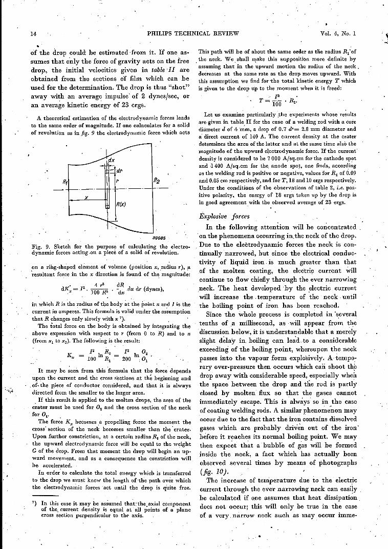
A theoretical estimation of the electrodynamic forces leadsto the same order of magnitude. If one calaculates for a solidof revolution as in fig. 9 the electrodynamic force which acts
x
3'0085
Fig. 9. Sketch for the purpose of calculating the electro-dynamic forces acting .on a piece of a solid of revolution.
on a ring-shaped element of volume (position x, ,radius r), ~~esultant force in the x direction is found of the magnitude:
• 2 4r3 dRdKx = 1 . 100 ffi . -dx dx dr (dynes),
in which R is the radius of the body at the point x and 1is thecurrent in amperes. This formula is valid under the assumptionthat R changes only slowly with x 7). ,The total force on the body is obtained by integrating the
above expression with respect to r (from 0 to R) and to x(from Xl to x2). The following i~ the result:
K 12 1 R2 12 1 O2x = 100 n R = 200 nO
1 , 1. .It may he seen from this formula that the force depends
upon the current and the cross sections at th~ beginning and~of- the piece of conductor considered, and that it is alwaysdirected from the smaller to the larger area.
o If this result is applied to the molten drops, the area of thecrater must be used for O2 and the cross section of the neckfor Ol' .
The force K", becomes a propelling force the moment thecross' section of the neck becomes smaller than the' crater.Upon further constriction, at a certain radius RI of the neck,the upward electrodynamic force will be equal to the weightG of the drop. From that moment the drop will begin an up-ward movement, and as a consequence the constriction willbe accelerated.
In order' to calculate the total energy which is transferredto the drop we must know the length, of the path over whichthe electrodynamic forces 'act until the drop is quite free.
7) In this case it may be assumed thattheaxiul componentof the. current density is equal at all points of a planecross section perpendicular to the axis.
This path will be of about the same order as tlie radius Rl'of. the neck. We. shall make this supposition more definite byassuming that in the upward motion the radius of the neck.decreases at the same rate as the drop moves upward. Withthis assumption we find for -the total kinetic energy T whichis given to the drop up to the moment when it is freed:
, 12 •
T = 100 . RI'. .
Let us examine particularly jhe experiments whose resultsare,given in table II for the case of a welding rod with a corediameter d of 4 mm, a drop of 0.7 d'= 2.8 mm diameter anda' direct current of 140 A. The current density at the craterdetermines the area of the latter and at the same time also themagnitude of the upward electrodynamic force. If the current'density is considered to be 7000 A/sq.cm for the cathode sp~tand -1400 A/sq.cm for the. anode spot, one finds" accordingas the welding rod is positive or negative, values for Rl of 0.09and 0.05 cm respectively, and for T, 18 and 10 ergs respectively.Under the conditions of the observations of table 2, i;e. pos-itive polarity, the energy of 18 ergs taken up by the drop isin good agreement. with the observed average ~f 23 ergs.
Éxplosive forces
In the following attention will be concentrated.on the phenomena occurring in.the neck of the drop.Due to the electrodynamic forces the neck is con-tinually .narrowed, hut since the electrical conduc-tivity of liquid iron, is much greater than thatof the molten coating, the electric current willcontinue to flow chiefly through the ever narrowing.neck. The heat developed 'by the electric currentwill increase the. temperature of the neck. untilthe boiling point of iron has been reached.. Since the whole process is completed in 'severaltenths of ,a millisecond, as -will appear from thediscussion below, it is understandable that a merelyslight delay in. boiling can lea'd. to a considerableexceeding of the boiling point, whereupon the neckpasses into the vapour form explosively. A tempo:rary over-pressure then occurs which caii shoot th~drop away with considerable speed, especially whenthe space between the drop and the rod is partlyclosed by molten flux so that the gases cannotimmediately escape. This is .always SO in the caseof coating welding rods. A similar phenomenon mayoccur due to the fact that the iron contains dissolvedgases which are probably driv~n out of the iron'before it reaches its normal boiling point. We maythen expect that a' bubble of gas will be formedinside the neck, a fact which has actually beenobserved several times by means of photographs(fig· 10J.The increase of température due to the electric
current through the ever narrowing neck can easilyhe calculated if one assumes that heat dissipationdocs not occur; this will only be true in the caseof a very. narrow neck such as may occur imme-
. I
•

.TANUA RY 1939 OVERHEAD WELDING :IS
diately before the explosion. The diameter of theneck can be estimated from observations of thevariation of voltage by means of a cathode rayoscillograph. It will he seen that every transferof a drop is accompanied by a voltage peak of about20 volts on the average with a welding currentof 140 A. The duration of this peak is of the orderof 2 . 10-4 sec.
•.29881
Fig. 10. Preparation for an explosion. A vapour or gas bubbleis formed in the interior of the neck.
This voltage peak may be ascribed chiefly to theelectrical resistance of the neck which can becalculated from it and is found to amount to 0.14ohm. If the neck is considered to be a cylinder 1mmin height (in agreement with the photographs) the
area ofthe cross section is found to be 3.6 '10-'1 sq.cm.The time which would be necessary to vaporize
this neck completely would be 6 . 10-4 sec at thegiven voltage and current. It is reasonable to assumethat the actual lifetime is only a fraction of thistime (in agreement with the observed value of2 . 10--4sec), because during the vaporization thenarrowing of the neck continues and, moreover,the speed of evaporation is thereby increased.
The fall in voltage in the neck during the transferof the drop does uot occur ouly in overhead weldingbut also in other positions. This voltage drop is inseries with the are voltage and may, if the availablevoltage is too low, lead to the extinction of the are .In welding with a welding transformer it has beenfound that the phenomenon of extinction of theare occurs at a no-load voltage of the machine whichis too low, and that it occurs often the lower theno-load voltage. For this reason transformers whichhave too Iowa no-load voltage (less than 50 voltsfor example) cannot be considered suitable as weld-ing transformers.
ILLUMINATION AND BLACK-OUTS
byP. J. BOUMA.
From a study of physiological data the brightnesses and intensities of illumination arededuced which under various circumstances are permissible in times of danger fromair-raid. General principles are given for the illumination at such times. It is shown howthe Philips "Protector" lamps provide a solution of the problem. In conclusion theinfluence of the colour of the light is briefly discussed.
The prohlem of planning a satisfactory outdoorillumination under normal conditions has alreadybeen discussed in this periodical from a number ofdifferent points of view. The problem takes on quitea different character when it is studied in connec-tion with a pbssible danger of air-raids in time ofwar.
The primary requirement made of the illumi-nation is that it must not enable the aviators toorient themselves or observe the position of cities,buildings, etc. There is then also the secondaryrequirement that on the ground there should behigh enough visihility so that traffic is still possible,although with very much reduced speeds.In the following the conditions will be studied
on the basis of physiological optical data for satis-fying the primary requirement of "non-visibilityfrom the air", and the way in which these conditionscan be realized in practice while retaining the hestpossible visibility on the ground.
Physiological optical basis
Accurate information about visibility of light
628.97 : 355.585
spots of different sizes and brightness under theconditions which hold for the observer in an aero-plane during an air-raid can only be obtained byexperiments on a large scale made by aviators fromthe air. Even then it will still be very hard toimitate actual conditions accurately. The observerwill in the tests usually flyover well-known country,the psychological factor is also quite different fromthat during an air-raid, etc. All such factors mayexert an influence on the result which should not beunderestimated.
Since we possess no reliable results of such prac-tical observations, we shall try to obtain the neces-sary numerical data in quite a different way. Weshall begin with the large amount of observationalmaterial which has been collected in numerouslaboratories on the visibility of objects of differentsize and brightness. Practical experience has,however, shown that under laboratory conditionsmuch low~r threshold values are obtained thanunder practically occurring conditions. In orderto solve this problem we shall make use of the