overdrive gearbox installation - michael hartman's …mhartman.net/files/sunbeam/od gearbox...
TRANSCRIPT
Overdrive Gearbox InstallationMichael Hartman
Version 1.1February 14, 2017
I inherit a Sunbeam Alpine Series V from my dad...and it sits in my garage for 8 years because the brakes have an issue and I am not really sure how to fix them. I am finally tired of ignoring the car and I dive in andaddress the brake issues. The car is going and stopping now. Time to register the car with DMV. I pop onto I-95 in the morning to take the car in for inspection. I just about get run over on the interstate in the rush hour traffic. The engine is revving high, but the car is going slow. It doesn't seem like it wants to go much faster than 55 mph in top gear.
I have a flashback to conversations between my dad and my brother many years ago...something about the Alpine really needing the overdrive gearbox...I now know firsthand what they were talking about.
I do some research on the old SAOCA forum posts and I see some folks have installed 5 speed transmissionsinto Alpines. I also see that Jeff Howarth has sold Laycock OD gearboxes that have been rebuilt by John Roseby. Apparently, John is the man for rebuilding the Laycock OD gearboxes.
Then an article is published in the Tiger's East / Alpine's East newsletter where two folks have installed OD gearbox kits purchased from Jeff Howarth. They are so excited about how the OD gearbox has changed theircar.
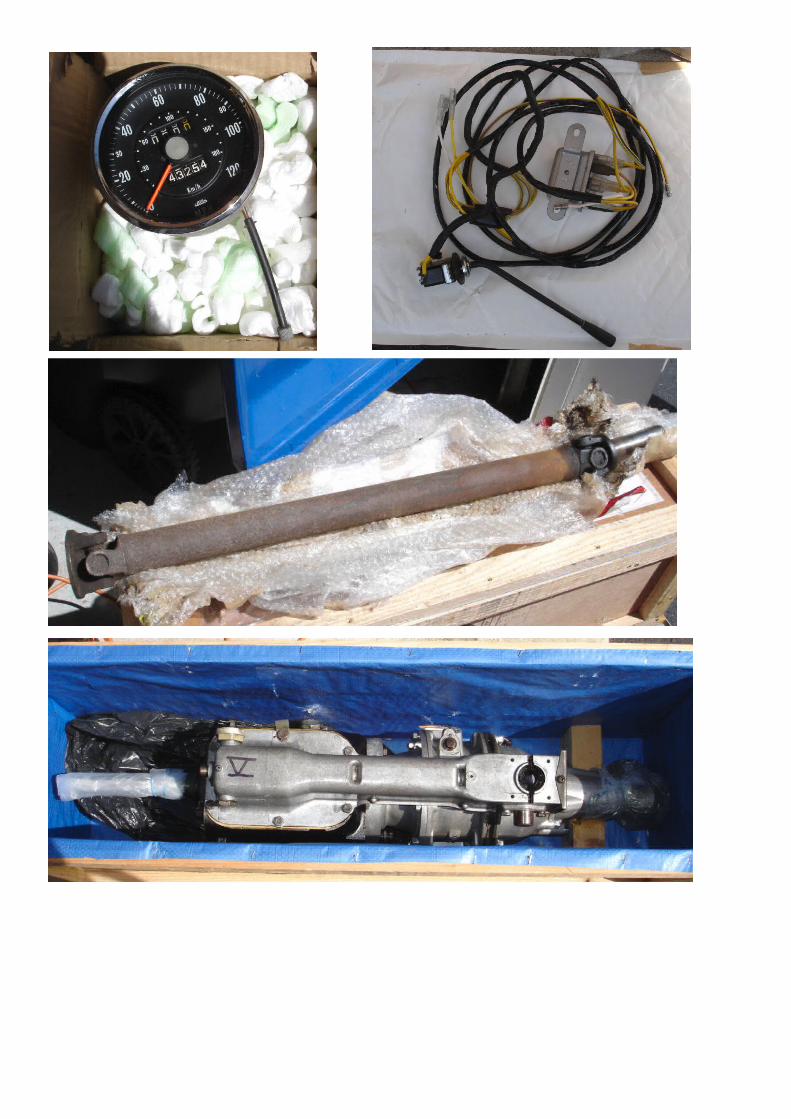
Jeff has recently posted on SAOCA that he has another rebuilt OD gearbox kit for sale. I exchange some messages with Jeff and learn the kit consists of the OD gearbox, OD relay, OD wiring loom, and OD steering column control switch. He can also supply an OD driveshaft for an additional amount and he can tryto find the proper OD speedometer for a series V. He does not have an OD speedometer cable.
My dad was striving to keep the Alpine stock during his restoration work. He had visions of concours judging in the future. I figure I should carry on his work and go for a Laycock OD gearbox, since they were an original option for the Alpine. After explaining to my wife the reasons I needed to spend so much money on an OD gearbox for a car sitting in our garage neglected for so many years, she gave me the greenlight.
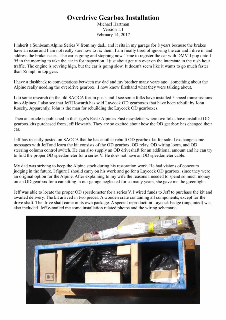
Jeff was able to locate the proper OD speedometer for a series V. I wired funds to Jeff to purchase the kit andawaited delivery. The kit arrived in two pieces. A wooden crate containing all components, except for the drive shaft. The drive shaft came in its own package. A special reproduction Laycock badge (unpainted) was also included. Jeff e-mailed me some installation related photos and the wiring schematic.
OD Speedometer Cable
I needed an OD speedometer cable, which is longer than the regular speedometer cable. I purchased a new speedometer cable from British Vintage Cables in Alberta, Canada. They have the original Smiths parts and dies to make cables. I had to research the proper length cable to order and the SAOCA forum provided the information.LHD 4 speed84" all cars up to B395002175 which is early series 575" from B395002176
LHD with Overdrive84" up to B39500218181" from B395002182
RHD 4 speed66" up to B39500218263" from B395002183
RHD with Overdrive72" up to B39500217866" from B395002175
OD Driveshaft
I purchased new U-joints from Sunbeam Specialties. I removed the original U joints from the driveshaft using a 20-ton press. I removed rust from all parts using distilled white vinegar. Painted parts black. Packed the new U-joints with Peak High Temp red grease NGLI #2.
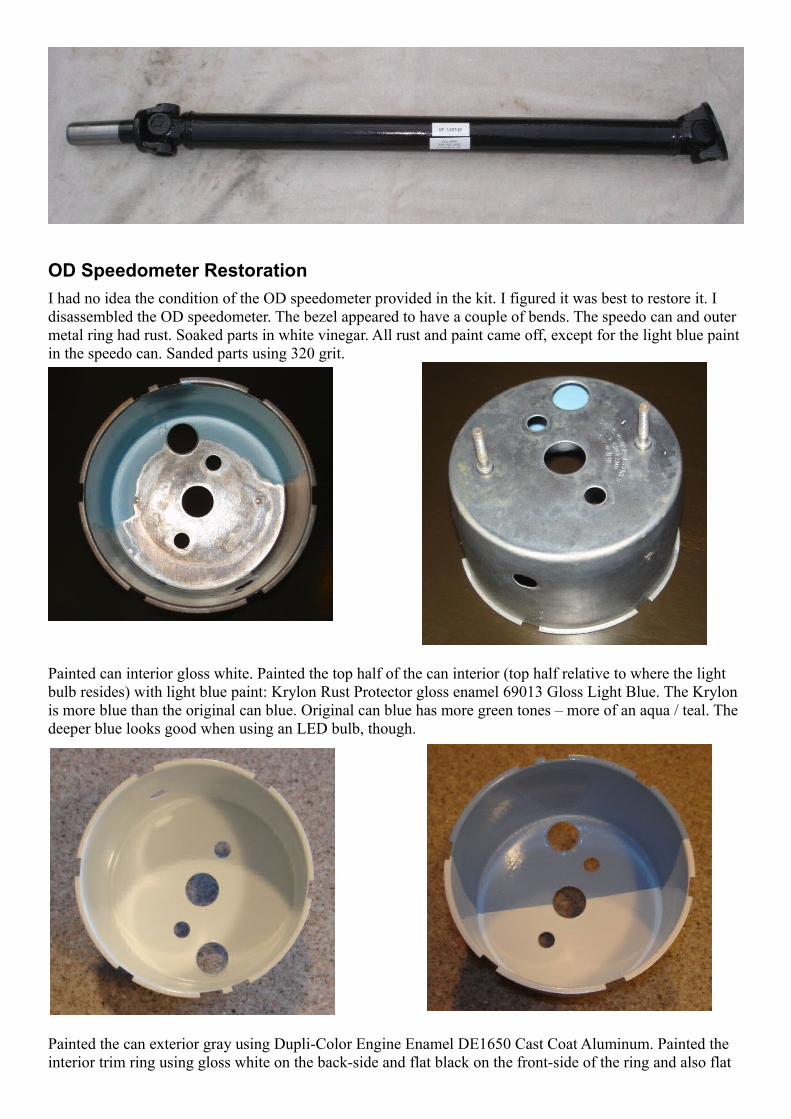
I learned that I did not need to remove the original U joints and do the painting. All I needed to do was give the driveshaft and new U-joints to the shop. Based on a recommendation, I used CCC Heavy Duty Truck Parts in the Philadelphia area. The gentleman who did the work was Rodney Schwartz. Rodney said the driveshaft had too much run-out, so he cut the welds and then re-welded. That brought the run-out to within spec. Rodney removed the old shaft balance weights, installed two new balance weights, and painted the whole shaft a gloss black.
When the driveshaft was returned to me, Rodney said I should purge the grease in the U-joints, so I purged the grease in the U-joints using the same Peak High Temp red grease I originally used to pack the joints.
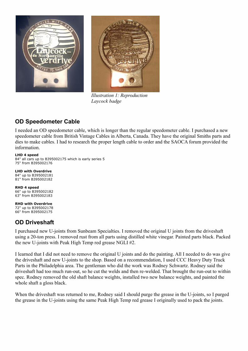
Illustration 1: Reproduction Laycock badge
OD Speedometer Restoration
I had no idea the condition of the OD speedometer provided in the kit. I figured it was best to restore it. I disassembled the OD speedometer. The bezel appeared to have a couple of bends. The speedo can and outer metal ring had rust. Soaked parts in white vinegar. All rust and paint came off, except for the light blue paint in the speedo can. Sanded parts using 320 grit.
Painted can interior gloss white. Painted the top half of the can interior (top half relative to where the light bulb resides) with light blue paint: Krylon Rust Protector gloss enamel 69013 Gloss Light Blue. The Krylon is more blue than the original can blue. Original can blue has more green tones – more of an aqua / teal. The deeper blue looks good when using an LED bulb, though.
Painted the can exterior gray using Dupli-Color Engine Enamel DE1650 Cast Coat Aluminum. Painted the interior trim ring using gloss white on the back-side and flat black on the front-side of the ring and also flat
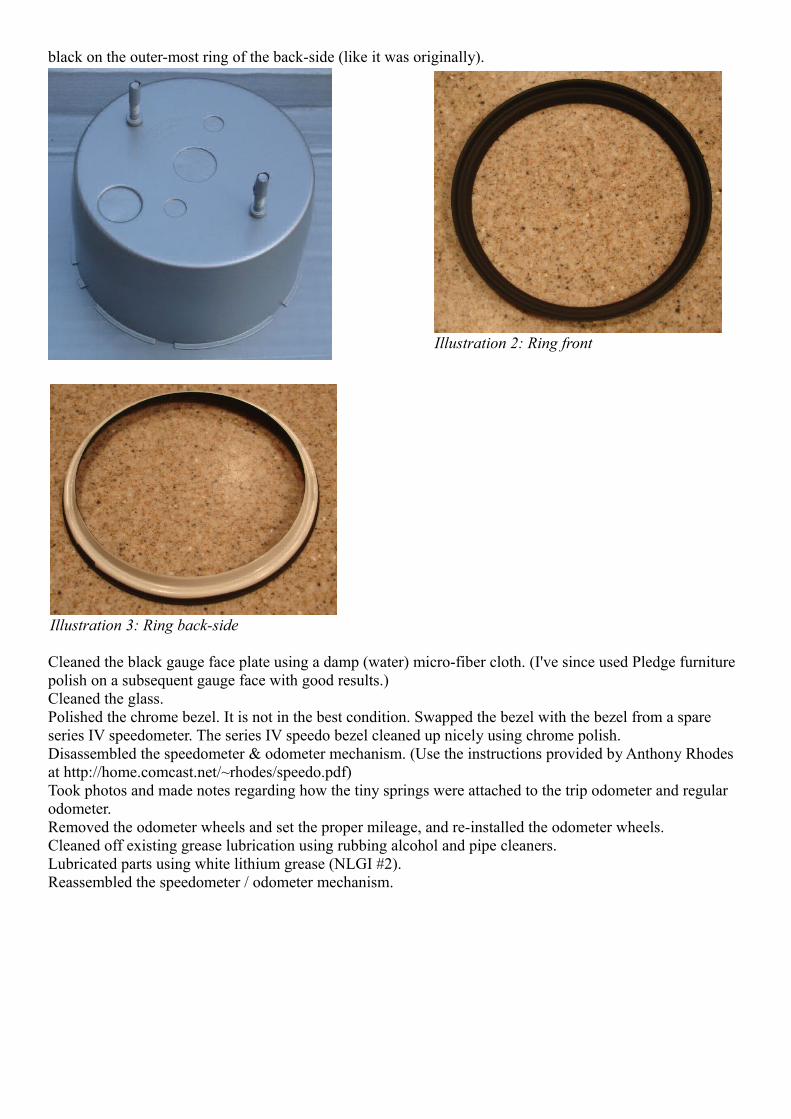
black on the outer-most ring of the back-side (like it was originally).
Cleaned the black gauge face plate using a damp (water) micro-fiber cloth. (I've since used Pledge furniture polish on a subsequent gauge face with good results.)Cleaned the glass.Polished the chrome bezel. It is not in the best condition. Swapped the bezel with the bezel from a spare series IV speedometer. The series IV speedo bezel cleaned up nicely using chrome polish.Disassembled the speedometer & odometer mechanism. (Use the instructions provided by Anthony Rhodes at http://home.comcast.net/~rhodes/speedo.pdf)Took photos and made notes regarding how the tiny springs were attached to the trip odometer and regular odometer.Removed the odometer wheels and set the proper mileage, and re-installed the odometer wheels.Cleaned off existing grease lubrication using rubbing alcohol and pipe cleaners.Lubricated parts using white lithium grease (NLGI #2).Reassembled the speedometer / odometer mechanism.
Illustration 2: Ring front
Illustration 3: Ring back-side
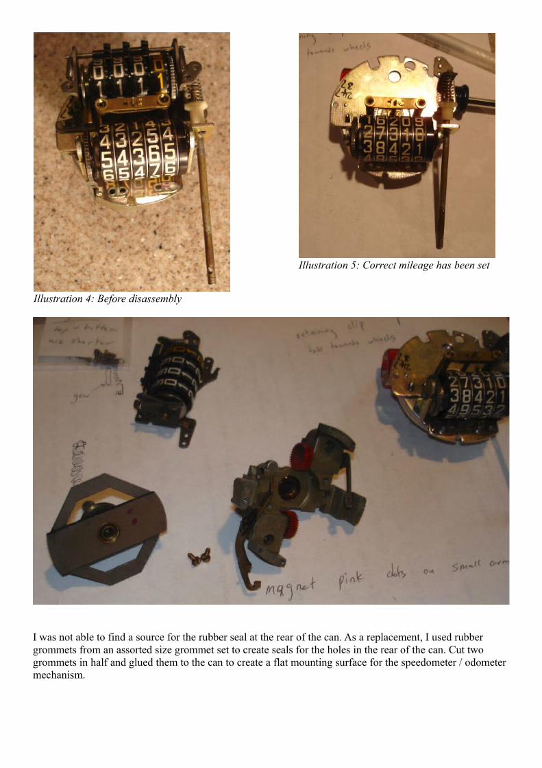
I was not able to find a source for the rubber seal at the rear of the can. As a replacement, I used rubber grommets from an assorted size grommet set to create seals for the holes in the rear of the can. Cut two grommets in half and glued them to the can to create a flat mounting surface for the speedometer / odometer mechanism.
Illustration 4: Before disassembly
Illustration 5: Correct mileage has been set
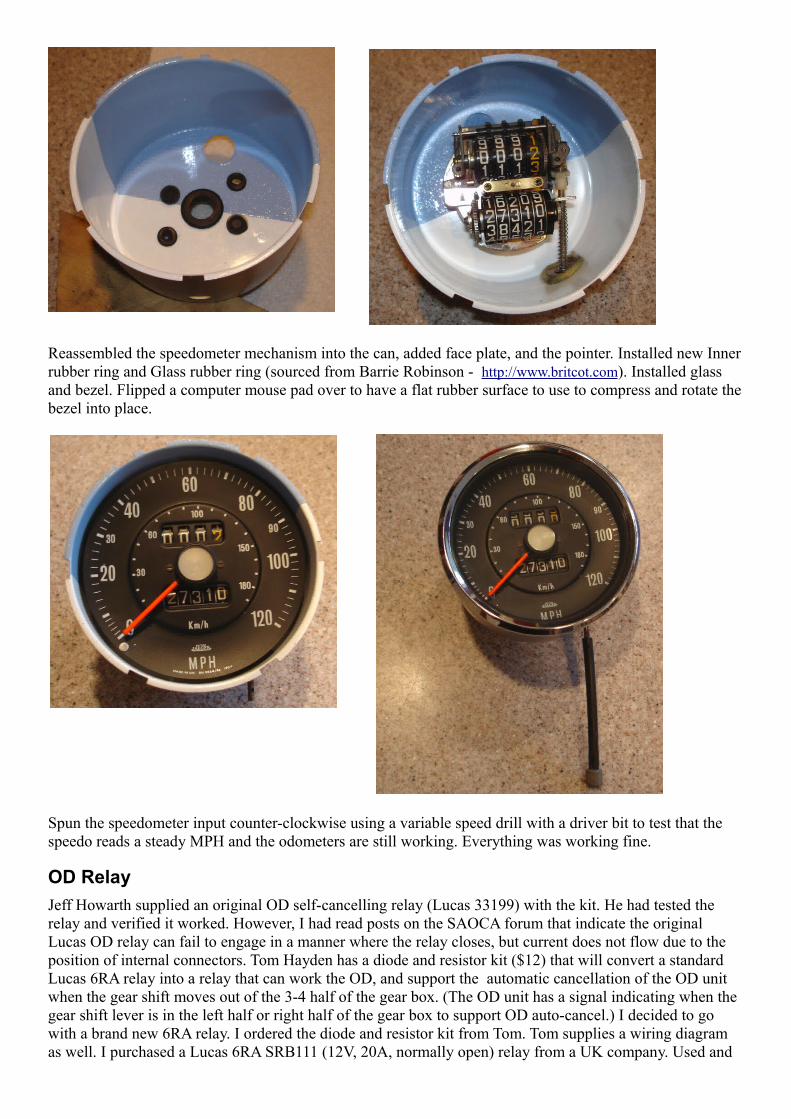
Reassembled the speedometer mechanism into the can, added face plate, and the pointer. Installed new Innerrubber ring and Glass rubber ring (sourced from Barrie Robinson - http://www.britcot.com). Installed glass and bezel. Flipped a computer mouse pad over to have a flat rubber surface to use to compress and rotate thebezel into place.
Spun the speedometer input counter-clockwise using a variable speed drill with a driver bit to test that the speedo reads a steady MPH and the odometers are still working. Everything was working fine.
OD Relay
Jeff Howarth supplied an original OD self-cancelling relay (Lucas 33199) with the kit. He had tested the relay and verified it worked. However, I had read posts on the SAOCA forum that indicate the original Lucas OD relay can fail to engage in a manner where the relay closes, but current does not flow due to the position of internal connectors. Tom Hayden has a diode and resistor kit ($12) that will convert a standard Lucas 6RA relay into a relay that can work the OD, and support the automatic cancellation of the OD unit when the gear shift moves out of the 3-4 half of the gear box. (The OD unit has a signal indicating when the gear shift lever is in the left half or right half of the gear box to support OD auto-cancel.) I decided to go with a brand new 6RA relay. I ordered the diode and resistor kit from Tom. Tom supplies a wiring diagram as well. I purchased a Lucas 6RA SRB111 (12V, 20A, normally open) relay from a UK company. Used and
new old stock Lucas 6RA relays are available online, but 50 year old parts might have internal corrosion. The new Lucas SRB111 relay appearance closely matches the vintage Lucas relays. It also has dual spades on the C1 connector, which can be useful for applying Tom's circuit modification.
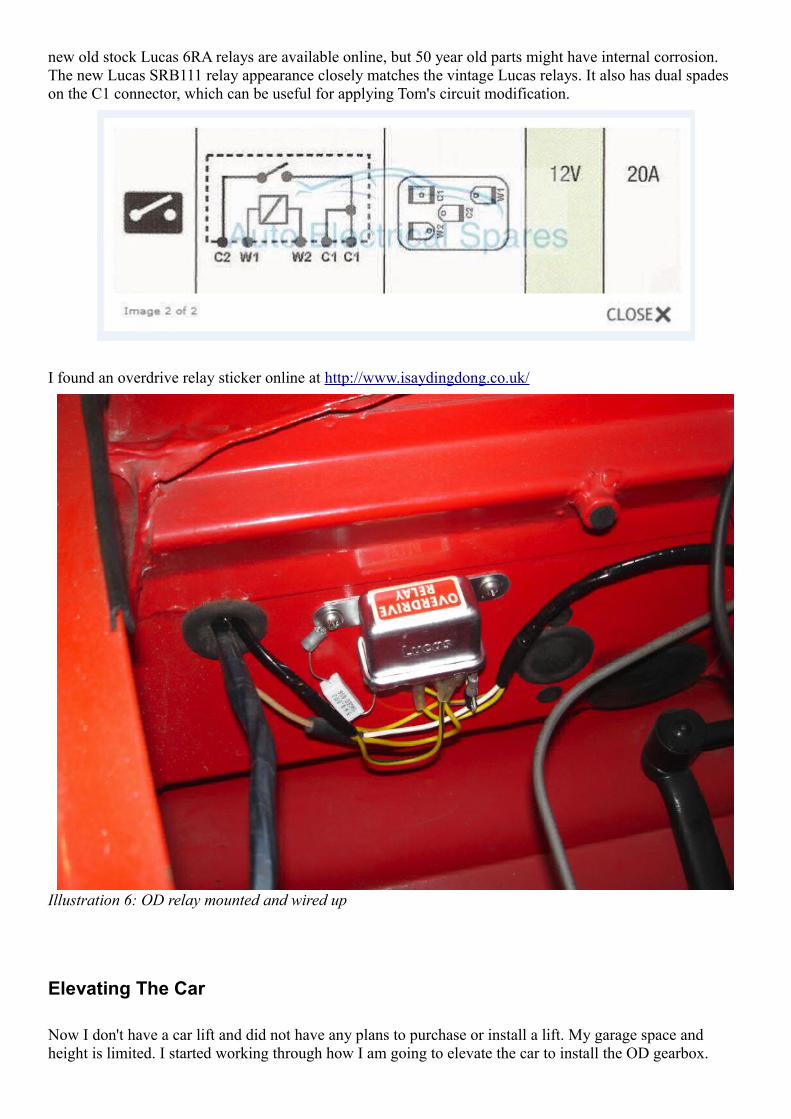
I found an overdrive relay sticker online at http://www.isaydingdong.co.uk/
Elevating The Car
Now I don't have a car lift and did not have any plans to purchase or install a lift. My garage space and height is limited. I started working through how I am going to elevate the car to install the OD gearbox.
Illustration 6: OD relay mounted and wired up
Maybe I should have figured that out before I purchased the overdrive kit, but I assumed I would be able to figure something out.
I posted to the SAOCA forum asking how high the car needs to be elevated to swap the geabox. I received a mix of replies about the height and also suggestions that removing both the engine and gearbox as a single unit is easier than just removing the gearbox. With the engine out, it is easier to align and attach the gearbox to the engine. If I had an engine lift, I probably would have pulled the engine and gearbox at the same time. Ido not have an engine lift.
I took some measurements to figure out how high the car needs to be elevated. I measured the distance from the ground to the bottom of the car. The height of the OD gearbox. Then looked at some minimum heights oftransmission lifts. Harbor Freight has an inexpensive transmission jack (Pittsburgh #39178 450 lb low lift jack) that has a minimum height of 7.25" and maximum height of 23.25". My conclusion is that with the gearbox sitting on the HF transmisson jack, I only need to elevate the car 12 inches for the jack + gearbox toclear the bottom of the car.
I avoid working under a car supported by jack stands when possible. They just don't seem like the most stable setup. I know someone who was crushed when his truck fell off a jack stand.
I researched drive-up ramps and some plastic tire platform blocks. Nothing too exciting there. During the web surfing, I find a guy who has made some wooden platforms for elevating his car. Each platform consistsof two blocks - a lower block and an upper block. His design has the car weight supported by a span at the lowest level, but then compression forces on up to the top. I don't see a need to have any spans and figure a setup where all the wood is under compression would be better. Doing some quick math, cheap pine 2x4s under compression in an alternating perpendicular arrangement should have a crush force of around 4,500 lbs at the intersection. Wood has variances in density / quality, so the crush force will likely be a bit less than4,500 lbs. If I build 4 platforms where each one can support a ball park of 4,500 lbs, there should be no concern with handling the Alpine's weight of 2,200 lbs.
When picking the lumber, I avoided boards with knots, since they create a weak spot.
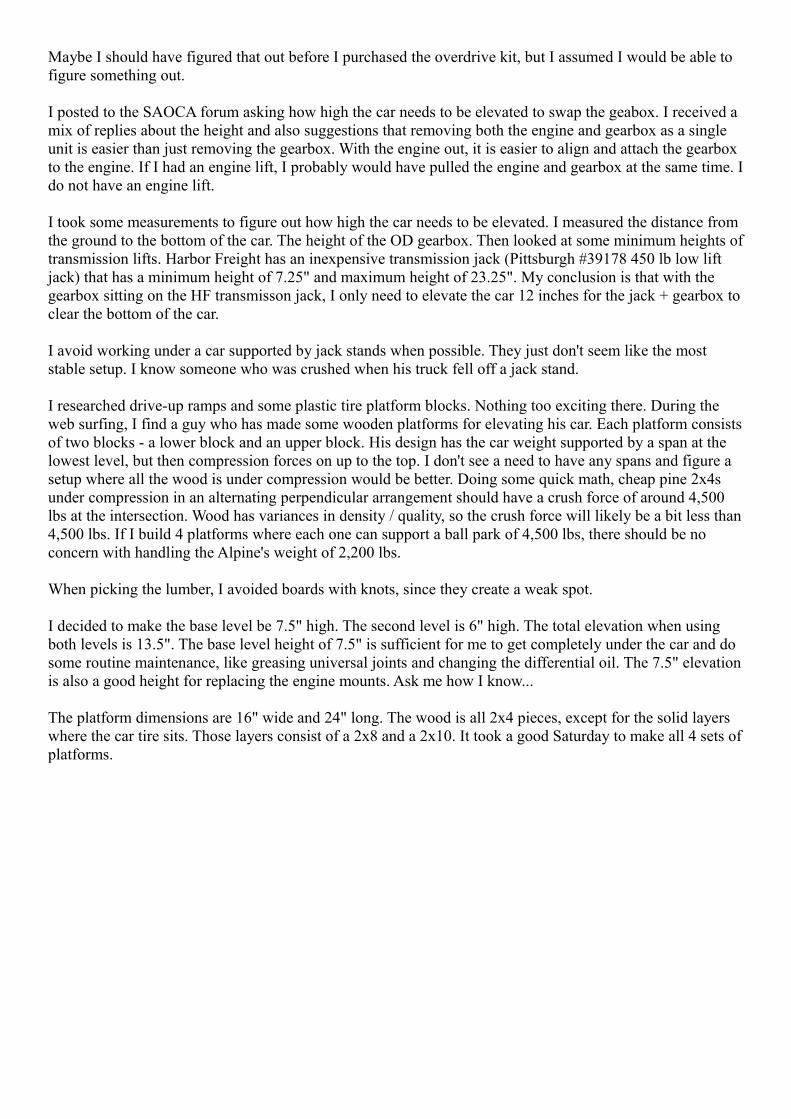
I decided to make the base level be 7.5" high. The second level is 6" high. The total elevation when using both levels is 13.5". The base level height of 7.5" is sufficient for me to get completely under the car and do some routine maintenance, like greasing universal joints and changing the differential oil. The 7.5" elevationis also a good height for replacing the engine mounts. Ask me how I know...
The platform dimensions are 16" wide and 24" long. The wood is all 2x4 pieces, except for the solid layers where the car tire sits. Those layers consist of a 2x8 and a 2x10. It took a good Saturday to make all 4 sets ofplatforms.
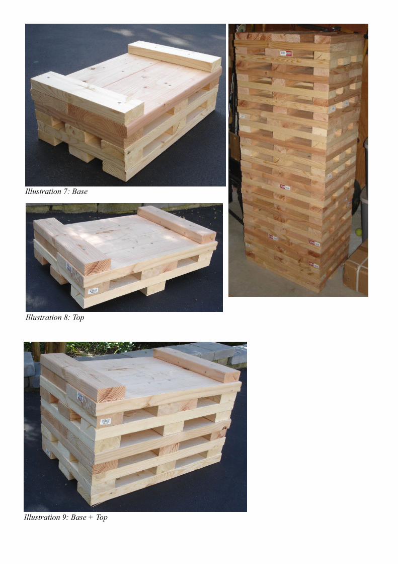
Illustration 7: Base
Illustration 9: Base + Top
Illustration 8: Top
I built a block to use when jacking the front cross member. Cut up an old rubber workout mat and glued it to the wood to provide some cushion, friction, and prevent scratches to the cross member. The raised 2x4 piece is oriented on the engine side of the cross member when jacking.
I had to jack the Alpine in stages to get it onto the platforms. First I jacked the rear (using the differential housing) using my floor jack and placed the rear tires onto the base platforms. Then I jacked the front of the car (using the block above on the front cross member) and placed the front tires onto the base platforms.
I ripped a 2x4 lengthwise and cut 16" lengths to create shims. I used two shims per platform, so the tires were blocked snugly on top of the platform.
For the second round of jacking, I needed to elevate my floor jack. I made a platform for the jack out of 2x6"s, a 2x8, a 2x10, and 3/4" plywood. The 2x6s were used on their sides for the base frame. Then a horizontal layer of a 2x8 and a 2x10. Then a sheet of 3/4" plywood on top. Overall dimensions are 16" x 36"x 7.75". I used the jack platform and repeated the process of jacking the rear and then the front to get the car tires onto the the second level of the wooden platforms.

When jacking the front the second time, the floor jack did not roll on the jack platform. I think the plywood was too soft. The car and platform tops moved forward instead of the jack rolling backwards. I used a sledgehammer to tap the bottom rear platforms forward as the jack pulled the platform tops and car forward. (Afterpondering this issue...when lowering the car off the platforms, I added a piece of cement backer board for bathroom tiling on top of the jack platform. The floor jack rolled ok on top of the jack platform when I added the cement backer board. The lesson is to have a hard surface on the top of the jack platform to ensurethe floor jack will roll.)
I then used 4 jack stands total (2 front and 2 rear) as back-ups for the wooden platforms.
Gearbox Removal
With the car elevated, it was time to remove the gearbox. I took many photos underneath the car and in the engine compartment. I wanted to make sure I had photos showing how things were originally assembled.
I followed the procedure documented in the 1725 workshop manual (WSM) for the most part.
• With the flexible plastic fuel line on the series V, I did not need to drain the gas tank nor disconnect the fuel line from the fuel pump.
• Drained the radiator.• Disconnected the upper and lower radiator hoses.• I removed the radiator. If I was not replacing the engine mounts, the radiator could have remained
installed. During gearbox removal, the engine tilts away from the radiator and poses no risk of contact. However, when replacing the engine mounts, the fan blades will hit the protective guard mounted to the top of the radiator.
• Disconnected the positive battery cable.• Removed the oil gauge pipe (a.k.a the oil filler pipe on top of the valve cover).
• Removed the flame trap and the hose that connects the flame trap to the Stromberg air filters.• I removed my Strombergs to have them rebuilt. If I was not removing the Strombergs, then remove
both air filters and remove the carb throttle linkages. Possibly disconnect or remove the heater hose that goes from the engine head to the heater control valve. The WSM says to remove the choke linkage as well. Not sure if that is needed.
• Removed the ignition coil. In retrospect, the coil does not need to be removed. Just disconnect the wires that go from the coil to the distributor.
• Disconnected the exhaust downpipe from the exhaust manifold. Mark the exhaust joints you will loosen, so you can match the original joint depth when reassembling. Loosened the clamp after the Yconnection. Loosened the clamp beyond the X crossmember. Rotated the exhaust pipe that connects to the exhaust manifold 180 degrees (so it pointed towards the ground), then was able to remove the 3 exhaust sections by sliding all 3 sections forwards as one piece.
• Removed the 4 driveshaft connection bolts and removed the driveshaft.• The WSM indicates to disconnect the clutch slave from the release bearing arm and the bell housing
and let the slave hang via the hydraulic pipe. I rebuilt the clutch hydraulics, so I removed the clutch master and slave cylinders and connecting pipe.
• Removed the starter.• Removed the center carpet piece, then the 4 screws that attach the gear shift lever. Removed gear
shift lever.• Removed the bell housing bolt that attaches the fuel line connector bracket to the bell housing.• Disconnected the speedometer cable from the gearbox.• Hindsight note: At this point, I should have slightly loosened the top-most bolts on the bell housing.
Once the engine was tilted backwards, it was a challenge to access these bolts and apply much torque.
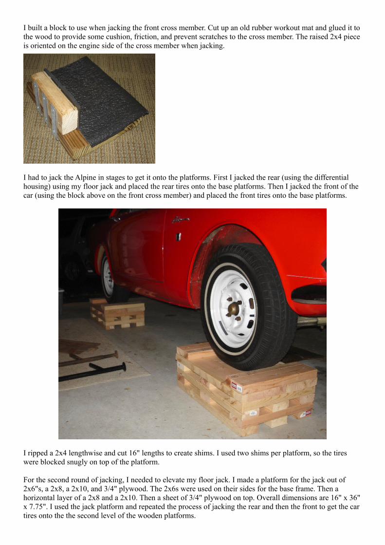
• Jacked up the tail of the gearbox slightly using a floor jack and a wood block to unweight the crossmember support.
• Removed the 8 bolts attaching the crossmember support to the car frame.• Removed the 3 bolts attaching attaching the crossmember support to the gearbox.
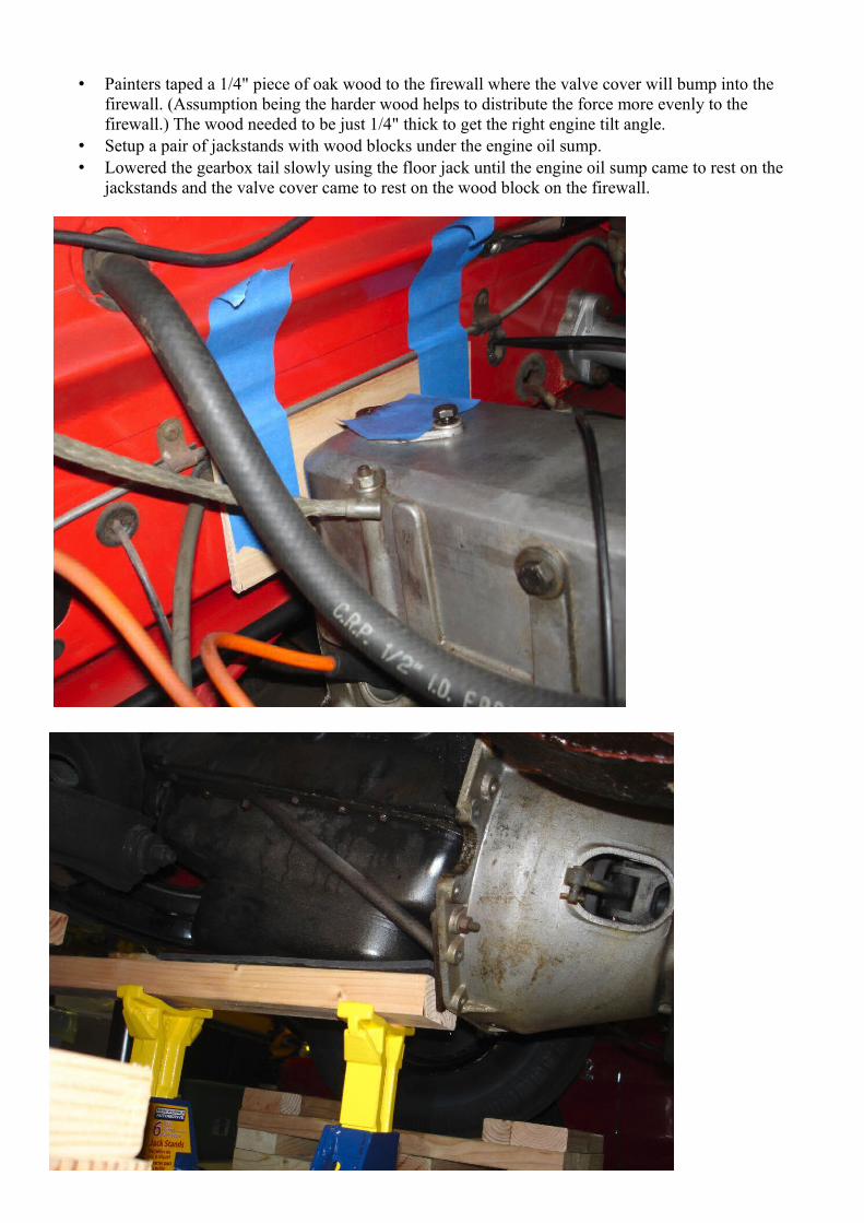
• Painters taped a 1/4" piece of oak wood to the firewall where the valve cover will bump into the firewall. (Assumption being the harder wood helps to distribute the force more evenly to the firewall.) The wood needed to be just 1/4" thick to get the right engine tilt angle.
• Setup a pair of jackstands with wood blocks under the engine oil sump.• Lowered the gearbox tail slowly using the floor jack until the engine oil sump came to rest on the
jackstands and the valve cover came to rest on the wood block on the firewall.
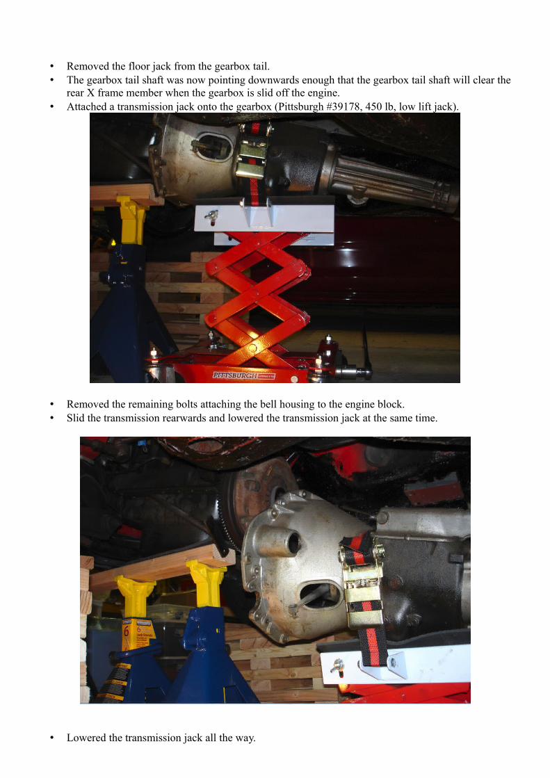
• Removed the floor jack from the gearbox tail.• The gearbox tail shaft was now pointing downwards enough that the gearbox tail shaft will clear the
rear X frame member when the gearbox is slid off the engine.• Attached a transmission jack onto the gearbox (Pittsburgh #39178, 450 lb, low lift jack).
• Removed the remaining bolts attaching the bell housing to the engine block.• Slid the transmission rearwards and lowered the transmission jack at the same time.
• Lowered the transmission jack all the way.
• Slid the gearbox + transmission jack out from under the car. The bell housing cleared right behind the back of the front tire.
• Since the gearbox is off, I inspected and replaced clutch components as needed.◦ Removed the clutch pressure plate and clutch disc. The pressure plate looked good.◦ The pilot bushing in the flywheel is worn and is loose.◦ Sent a spare clutch disc out to be rebuilt.◦ Purchased a new pilot bushing and release bearing.◦ Soaked the new pilot bushing in engine oil for many days.◦ Cleaned the flywheel face, pressure plate dowels, and pilot bushing area using rubbing alcohol.◦ Put the pilot bushing in the freezer overnight to shrink it. Hammered the new pilot bushing into
place using a socket and rubber mallet.◦ Moved the clutch disc back and forth on the OD gearbox shaft to lubricate the spines with grease
and capture excess grease from the splines.◦ Positioned the clutch disc and clutch pressure plate into place on the flywheel. Used a plastic
clutch alignment tool purchased from Sunbeam Specialties to center the clutch disc properly behind the pressure plate. Tightened the clutch pressure plate bolts to 17 lb-ft (they are 5/16" fine thread bolts with dry threads). Tightened bolts in an equal manner, 1 quarter turn at a time, via a star / diagonal process, to avoid warping the pressure plate.
◦ Replaced the clutch release bearing. Greased (using white lithium grease) all pivot points & the two positioning springs.
• I cleaned, sanded, and painted the varous parts that were removed, such as the cross member, transmission support bracket, bell housing plate, bolts, nuts, etc.
• Transferred the bell housing to the OD gearbox. Torqued 3/8 bolts & the one nut to 23 lb/ft. Torqued the top clutch pivot bolt that attaches only to the aluminum bell housing to just 10 lb/ft. (All bolts & nut threads were oiled, hence used reduced torque amounts.)
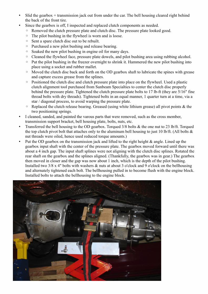
• Put the OD gearbox on the transmission jack and lifted to the right height & angle. Lined up the gearbox input shaft with the center of the pressure plate. The gearbox moved forward until there was about a 4 inch gap. The input shaft splines were not aligning with the clutch disc splines. Rotated the rear shaft on the gearbox and the splines aligned. (Thankfully, the gearbox was in gear.) The gearbox then moved in closer and the gap was now about 1 inch, which is the depth of the pilot bushing. Installed two 3/8 x 4" bolts with washers & nuts at about 3 o'clock and 9 o'clock on the bellhousing and alternately tightened each bolt. The bellhousing pulled in to become flush with the engine block. Installed bolts to attach the bellhousing to the engine block.
• Used the floor jack to raise the gearbox. The tail of the gearbox cleared the X frame member with no issue.
• Installed the gearbox mounting plate, new gearbox rubber mounts and the crossmember support.• Replaced the front engine mounts by jacking the oil sump to unweight the mounts. Later on, I
discovered the engine mount rubber was too hard. I had to replace the engine mounts with ones purchased from Rootes Parts Service in Holland.
• Installed the gear shift lever. Two of the pan head bolts are shorter than the other two (and need to be shorter to tighten fully).
• Put the gearbox into neutral.• Attached the driveshaft yoke, and rotated the shaft to align the rear driveshaft mounting holes. The
painted area of the yoke is just shy (maybe 1/2") of the gearbox rear seal.• Filled OD gearbox with 2.7 quarts of 20W-50 oil.• Reattached the bell housing bolt that has the fuel line connector bracket.• Reinstalled starter.• Reinstalled clutch slave, master, and new hydraulic pipe. Custom fabricated a hose clamp setup and
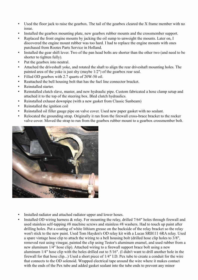
attached it to the top of the steering box. Bled clutch hydraulics.• Reinstalled exhaust downpipe (with a new gasket from Classic Sunbeam)• Reinstalled the ignition coil• Reinstalled oil filler gauge pipe on valve cover. Used new paper gasket with no sealant.• Relocated the grounding strap. Originally it ran from the firewall cross-brace bracket to the rocker
valve cover. Moved the strap to run from the gearbox rubber mount to a gearbox crossmember bolt.
• Installed radiator and attached radiator upper and lower hoses.• Installed OD wiring harness & relay. For mounting the relay, drilled 7/64" holes through firewall and
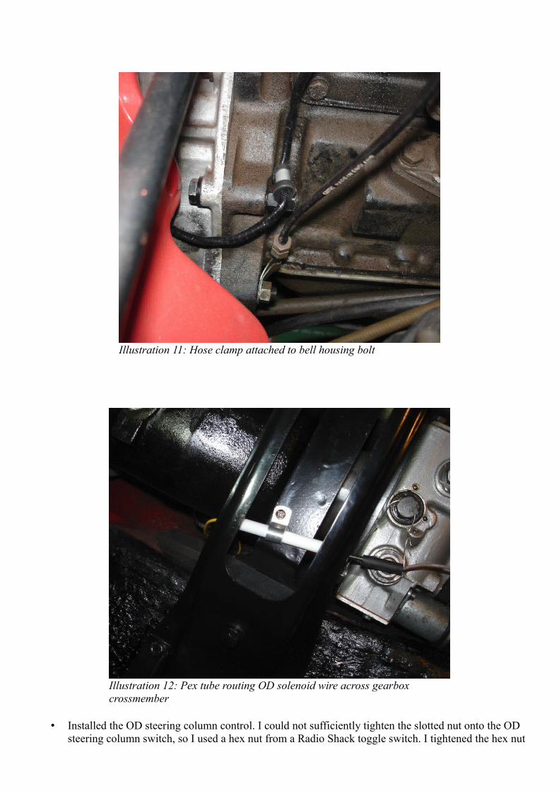
used stainless self-tapping #8 machine screws and stainless #8 washers. Had to touch up paint after drilling holes. Put a coating of white lithium grease on the backside of the relay bracket so the relay won't stick to the new paint. Used Tom Hayden's OD relay kit with a Lucas SRB111 6RA relay. Useda spare vintage hose clip to attach the wiring to a bell housing bolt (drilled hose clip holes to 3/8", removed rust using vinegar, painted the clip using Testor's aluminum enamel, and used rubber from anew aluminum 1/4" hose clip). Attached wiring to a firewall support brace bolt using a new aluminum 1/4" hose clip with the holes drilled out to 5/16". (I didn't want to drill another hole in the firewall for that hose clip...) Used a short piece of 1/4" I.D. Pex tube to create a conduit for the wire that connects to the OD solenoid. Wrapped electrical tape around the wire where it makes contact with the ends of the Pex tube and added gasket sealant into the tube ends to prevent any minor

rubbing. Attached the Pex tube to the gearbox support bracket using an aluminum 1/4" hose clip and a stainless #8 machine screw and stainless #8 washer. The gearbox support bracket already had a hole drilled in it, so I figured the hole might be for clamping the OD solenoid wire. (Turns out that is not the case, but the hole worked great anyways.)
Illustration 10: Hose clamp attached to engine bay brace bolt
• Installed the OD steering column control. I could not sufficiently tighten the slotted nut onto the OD steering column switch, so I used a hex nut from a Radio Shack toggle switch. I tightened the hex nut
Illustration 12: Pex tube routing OD solenoid wire across gearbox crossmember
Illustration 11: Hose clamp attached to bell housing bolt
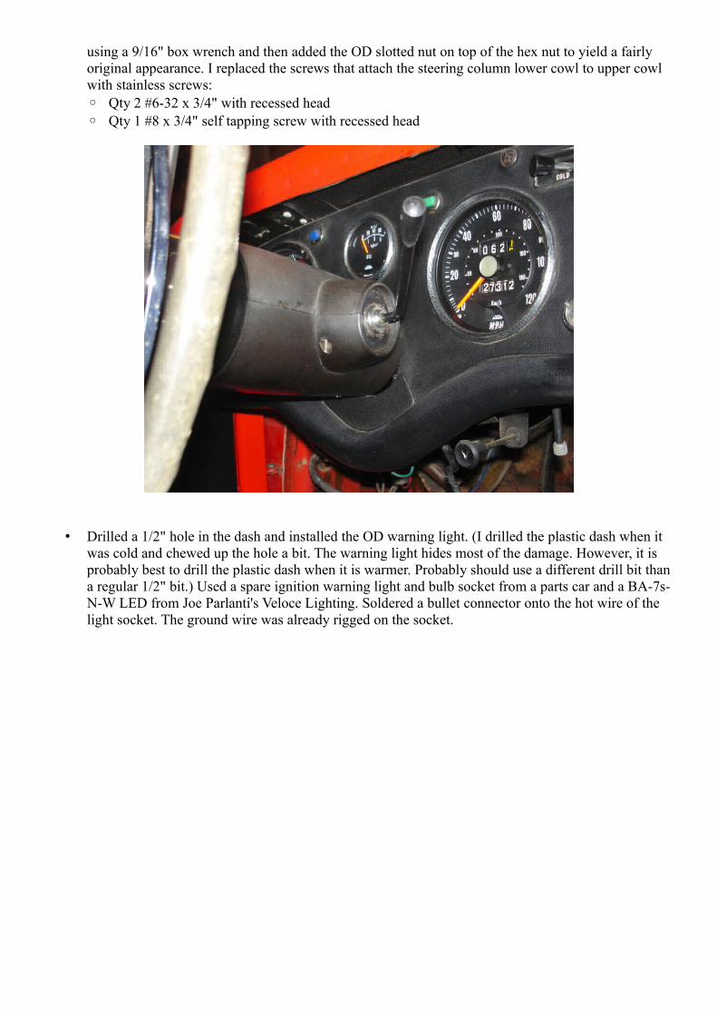
using a 9/16" box wrench and then added the OD slotted nut on top of the hex nut to yield a fairly original appearance. I replaced the screws that attach the steering column lower cowl to upper cowl with stainless screws:◦ Qty 2 #6-32 x 3/4" with recessed head◦ Qty 1 #8 x 3/4" self tapping screw with recessed head
• Drilled a 1/2" hole in the dash and installed the OD warning light. (I drilled the plastic dash when it was cold and chewed up the hole a bit. The warning light hides most of the damage. However, it is probably best to drill the plastic dash when it is warmer. Probably should use a different drill bit than a regular 1/2" bit.) Used a spare ignition warning light and bulb socket from a parts car and a BA-7s-N-W LED from Joe Parlanti's Veloce Lighting. Soldered a bullet connector onto the hot wire of the light socket. The ground wire was already rigged on the socket.
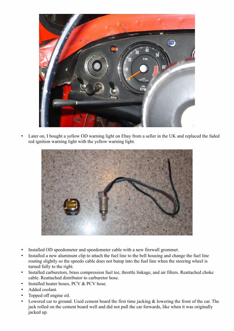
• Later on, I bought a yellow OD warning light on Ebay from a seller in the UK and replaced the fadedred ignition warning light with the yellow warning light.
• Installed OD speedometer and speedometer cable with a new firewall grommet.• Installed a new aluminum clip to attach the fuel line to the bell housing and change the fuel line
routing slightly so the speedo cable does not bump into the fuel line when the steering wheel is turned fully to the right.
• Installed carburetors, brass compression fuel tee, throttle linkage, and air filters. Reattached choke cable. Reattached distributor to carburetor hose.
• Installed heater hoses, PCV & PCV hose.• Added coolant.• Topped off engine oil.• Lowered car to ground. Used cement board the first time jacking & lowering the front of the car. The
jack rolled on the cement board well and did not pull the car forwards, like when it was originally jacked up.

• Reattached battery cable.• Cranked the engine a bit without pulling the choke to allow the oil pressure to build up some.• Applied the choke and the car started up.• Depressing the clutch does not stop the gearbox input shaft from spinning – unable to select a gear.
Hmm...• Bled the clutch hydraulics. It seemed like some air may have been purged. Was able to get the
gearbox into gear with the engine running, but the input shaft seemed to still be spinning slowly. The car felt like it was pushing forwards with the clutch depressed. Turned the car off. Blocked the wheels, applied the handbrake and started the car in reverse gear with the clutch depressed. Revved the engine some while remaining in gear with the clutch depressed. Clutch now fully disengages the gearbox input shaft. Moved the car in and out of the garage a few times.
• Drove the car and tested the overdrive. Everything is working. The speedometer is accurate based on a radar speed sign I drove by.