ov/3-4 overview of the ftu results -...
TRANSCRIPT
OV/3-4
1
Overview of the FTU results
V. Pericoli-Ridolfini, A. Alekseyev1, B. Angelini, S.V. Annibaldi, M.L. Apicella, G. Apruzzese,E. Barbato, J. Berrino2, A. Bertocchi, W. Bin2, F. Bombarda, G. Bracco, A. Bruschi2, P. Buratti,G. Calabrò, A. Cardinali, L. Carraro3, C. Castaldo, C. Centioli, R. Cesario, S. Cirant2, V.Cocilovo, F. Crisanti, G. D’Antona4, R. De Angelis, M. De Benedetti, F. De Marco, B. Esposito, D.Frigione, L. Gabellieri, F. Gandini2, E. Giovannozzi, G. Granucci2, F. Gravanti, G. Grossetti2, G.Grosso2, F. Iannone, H. Kroegler, V. Lazarev1, E. Lazzaro2, M. Leigheb, L. Lubyako5, G .Maddaluno, M. Marinucci, D. Marocco, J.R. Martin-Solis6, G. Mazzitelli, C. Mazzotta, V.Mellera2, F. Mirizzi, G. Monari, A. Moro2, V. Muzzini2, S. Nowak2, F. Orsitto, L. Panaccione, M.Panella, L. Pieroni, S. Podda, M. E. Puiatti3, G. Ravera, G. Regnoli, F. Romanelli, M. Romanelli,A. Shalashov5, A. Simonetto2, P. Smeulders, C. Sozzi2, E. Sternini, U. Tartari2, B. Tilia, A.A.Tuccillo, O. Tudisco, M. Valisa3, A. Vertkov7, V. Vitale, G. Vlad, R. Zagórski8, F. Zonca
Associazione Euratom-ENEA sulla Fusione, C.R. Frascati, 00044, Frascati, Roma, Italye-mail contact of main author: [email protected]
Abstract. Steady internal transport barriers (ITB) are obtained in FTU almost full non-inductive current drive (CD)discharges at ITER relevant magnetic field and density (ne0≥1.3·1020 m-3). The heating power is to electrons with nomomentum input similar to ITER condition. Two RF systems, lower hybrid (LH) and electron cyclotron (EC),provide the CD and power sources. The energy confinement time exceeds the ITER 97-L scaling by about 1.6 times.The barrier dynamics is unaffected by ion collisional heating: turbulence is strongly suppressed and the ion transportremains at the ohmic level. ITB radius on FTU can be varied between 0.2≤r/a≤0.65 modifying the LHCD depositionprofile and the safety factors q or via ad hoc use of co/counter ECCD. Feedback control/suppression of MHD tearingmodes (TM, m=2) with EC waves relies on a real-time detection of the TM and of its radial location. A liquidlithium limiter (LLL) of novel design, composed of a mesh of porous capillaries, has been tested successfully for thefirst time on a medium size tokamak. The LLL surface showed no damage up to the maximum thermal load of 5MW/m2. With LLL cleaner plasmas are obtained and the particle recycling strongly drops; new interesting regimesof particle transport arise at high density. Progress on disruption mitigation by means of EC power has been made.Testing the collective Thomson scattering in ITER-relevant configuration has stressed that avoiding backscatteredradiation to the source is very crucial. The theory of the evolution of fishbone-like instabilities driven by LHgenerated supra-thermal electrons in FTU is outlined, and its relation to the trapped α particles dynamics is stressed.
1. Introduction
FTU is a compact high magnetic field tokamak (major radius R=0.93 m, minor radius a=0.3 m,toroidal magnetic field BT≤8 T, plasma current Ip≤1.6 MA) aimed at developing advancedscenarios at magnetic field and densities relevant to ITER operation, as well as its supportingphysics [1]. The FTU auxiliary heating systems, lower hybrid (LH, frequency fLH=8 GHz, powerPLH≤2 MW) and electron cyclotron (EC, fEC=140 GHz, power PEC≤1.6 MW) waves, heatelectrons (e-) and inject no momentum. As in ITER, ions (i+) are heated only by e--i+ collisions.
Since the last FEC [2], the main hardware upgrades have been the installation of a system for realtime MHD mode detection and control by EC heating (ECH), of a new liquid lithium limiter
1 TRINITI, Troitsk, Moscow reg., Russia2 Associazione EURATOM-ENEA, IFP-CNR, Via R. Cozzi, 53 - 20125 Milano, Italy3 Consozio RFX, Corso Stati Uniti 4, I-35100, Padova, Italy4 Politecnico di Milano, Piazza Leonardo Da Vinci 32, 20133 Milano, Italy5 Institute of Applied Physics, Russian Academy of Science, Nizhny Novgorod, Russia6 Universidad Carlos III de Madrid, Avenida de la Universidad 30, 28911 Madrid, Spain7 FSUE, “RED STAR”, Moscow, Russia8 Institute of Plasma Physics and Laser Microfusion, EURATOM Association, 01-497, Warsaw, Poland
OV/3-4
2
(LLL) that has broadened the FTU capability of studying plasmas with different wall conditions,and of a new motional Stark effect and charge exchange recombination spectroscopy(MSE/CXRS) diagnostic, presently being commissioned, to provide information on the safetyfactor, q, and ion temperature profiles. A collective Thomson scattering system in the microwavefrequency range (f=140 GHz) has been tested for the first time in an ITER-like configuration. ALH multijunction launcher has been also tested, reaching a power density of 8 kW/cm2 at 8 GHz.
In this paper, the main new results from the FTU experimental campaigns will be presentedstarting from the insights gained in the advanced tokamak scenarios, Sect. 2, followed by theresults in the active control of the magnetohydrodynamic (MHD) instabilities with the EC power,Sect. 3. In Sect. 4 we will describe the result obtained with LLL. Theoretical understanding of theelectron fishbones instability dynamics will be presented in Sect. 5. Finally in Sect. 6 the activityin support of ITER (disruption mitigation, study of LH disruptions, CTS diagnostic test andphysics studies) will be summarized together with the results on the physics of LH propagation.A short summary of the perspective for the years 2006-2008 will be given finally in sec. 7.
2. Advanced Tokamak Scenarios
The aspect more relevant to an ITER like internal transport barriers (ITB) addressed by the FTUprogram concerns influence of the high density and electron-ion collisional coupling on themechanisms that produce the e-ITBs, The possibility to verify if an ion transport barrier coulddevelop in presence of e- heating only would be very important to clarify the role of the manymechanisms candidates to stabilize the ion turbulence. Conversely, FTU cannot deal withquestions such as stability at high ßp (ßp=2µ0<p>/<Bpa>
2 is the poloidal beta, µ0=vacuummagnetic permeability, <p> average plasma pressure, <Bpa> average poloidal field strength at theplasma boundary), due to its high magnetic field, the role of fast particles and the divertorphysics, FTU being a limiter device. Further details on FTU can be found in Ref. [1].
Stationary ITB regimes, candidates as a steady scenario for ITER, have been established inalmost full current drive (CD) conditions at the ITER working density and magnetic field, BT. Aprevious work [3] reported on the high density steady ITBs, with the central density ne0≥1.3·1020
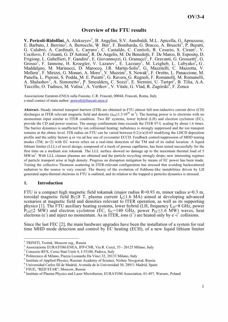
m-3 (ne0/nGW≥0.9, nGW=Greenwald value [4]. and electron temperature Te0≥5 keV. The energyconfinement time is enhanced by 1.6 times respect to the ITER97-L scaling, applicable to FTU,and ion collisional heating does not affect the barrier dynamics. The barrier was however notwide. Since the last FEC, methods to control the barrier radial width by LH current drive (LHCD)have been successfully developed, even though limited so far to lower density regimes. SteadyITB radii up to r/a≤0.67 have been obtained by peripheral LH absorption, favored primarily byoperation at low safety factors q [5]. The time traces of the most relevant parameters of a steadywide barrier are presented in Fig. 2.1
The usual q(r) shape in an ITB has a central value 1<q0<2, followed by a low or even weaklyinverted magnetic shear region with qmin≈1.2-1.3 (shear is defined as s=r/q·dq/dr) at the end ofwhich is located the ITB foot, generally close to qmin≈1.5 [6]. If rITB≈a/2 the q(r) profileresembles that of typical hybrid regimes [7]. The link in FTU of the ITB foot with a low-orderrational q-value surface agrees well with JET observation [8], despite the quite different ITBgenesis. These are obtained at JET, and also at JT60-U [9], with a very early heating or CD notallowed in FTU by various constraints [10], when q(r) is very far from the relaxed shape andshow remarkably reversed shears and qmin>2.
The EC power is mainly used to heat (ECH) inside the barrier to benefit of the reduced energytransport. This in turn reinforces the barrier: the electron temperature gradient increasesimproving further the energy confinement as illustrated previously [6]. EC current drive (ECCD)is often a precious auxiliary tool either in co- or counter (ctr-) configuration in building theproper current profile. In the case of Fig. 2.1 co-ECCD slightly off-axis (rECCD~0.2·a,
OV/3-4
3
rECCD=minor radius of the ECCD deposition) facilitates steadiness, whereas on-axis ctr-ECCD isnecessary for building high density ITBs,
€
n e≈1020 m-3 [11, 10].
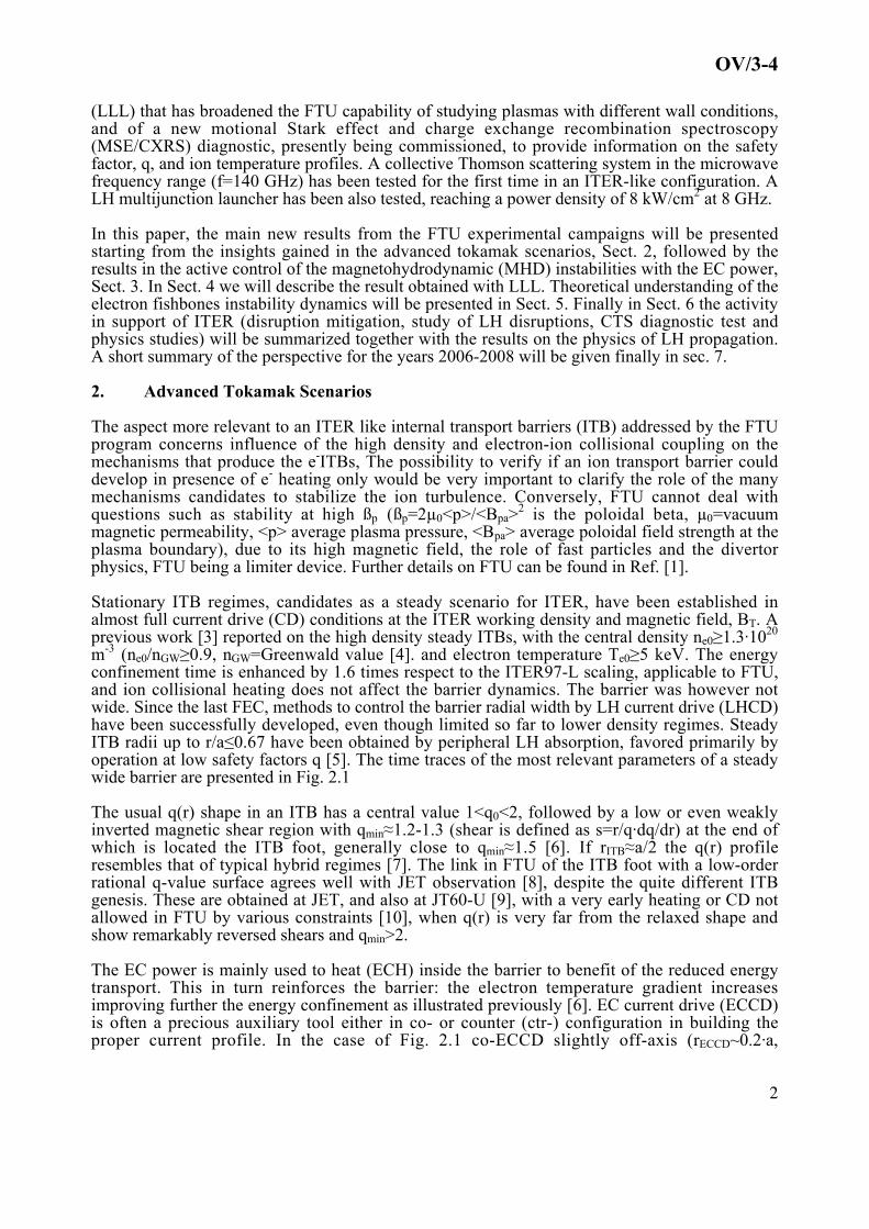
The ITB energy confinement improves with the barrier strength, but tends to saturate for strongITBs, as shown in Fig. 2.2. Here we plot the enhancement factor H97-L=τE/τE97-L versusρ*
T=ρL,s/LT (τ E=experimental energy confinement time, τE97= ITER97-L scaled value of τE,ρL,s=Larmor radius of the ions with the sound velocity is normally assumed as a measure of thebarrier strength, and LT=Te/(dTe/dr)). Clearly the improvement improves very rapidly close to thethreshold value ρ*
T,th=0.014 [10], and seems to saturate at H97-L≈1.7. The best confinementpertains to points with ECH. The quite high correlation degree between H97-L and ρ*
T leaves littleweight to the barrier width. This is not surprising if the ITB is modeled as a high confinementcore, with a defined confinement time τh, surrounded by a poor confinement region. Theadditional power Ph deposited inside the core would raise its energy and consequently that of theentire plasma by the amount Ph·τh, irrespective of its width.
FIG. 2.1 - Time evolution of the most significant parametersfor #27928, the widest steady ITB; co-ECCD configurationslightly off axis (≈6 cm). Ip=0.51 MA, BT=5.3 T, qa≈5.5
FIG. 2.2 - Global energy confinementof the ITBs, shown as the enhancementover the ITER97-L scaling versus thebarrier strength
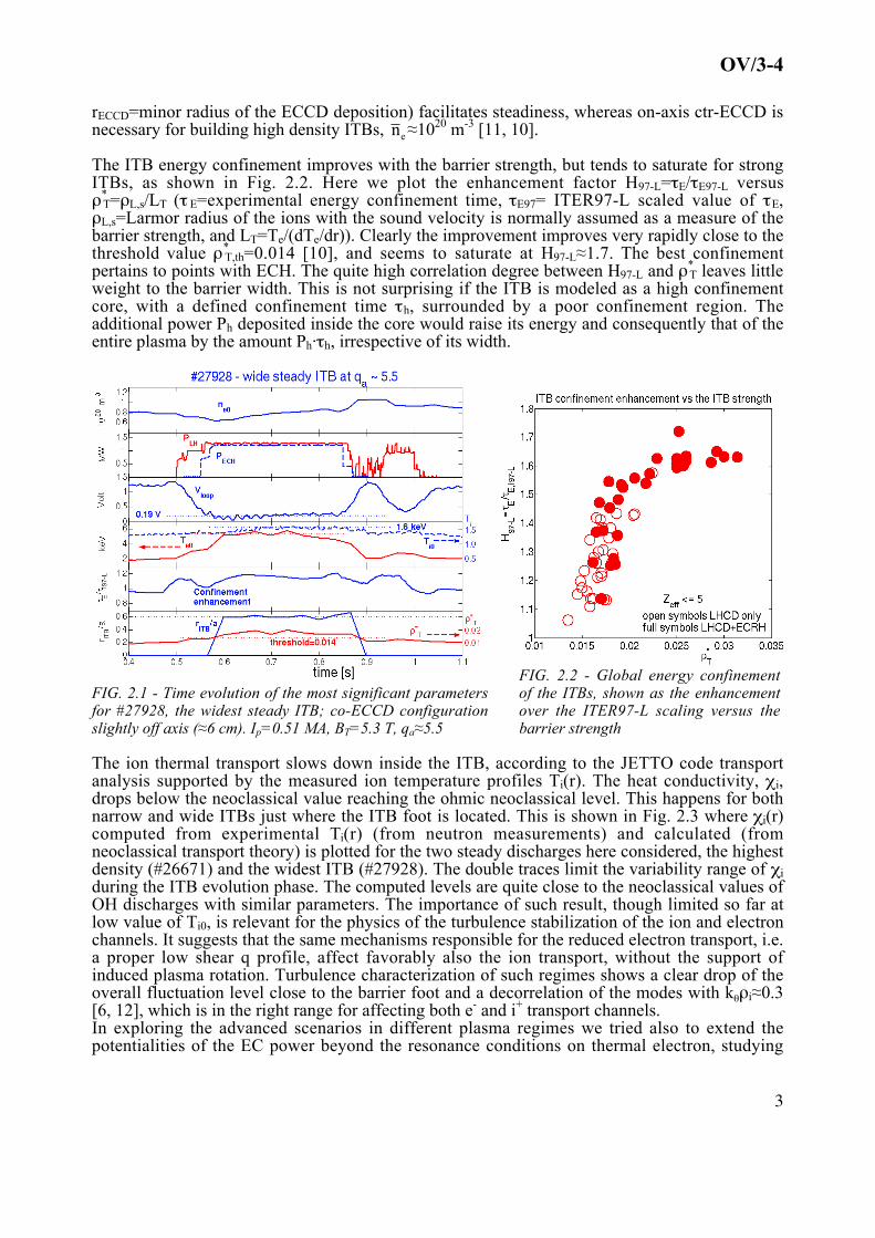
The ion thermal transport slows down inside the ITB, according to the JETTO code transportanalysis supported by the measured ion temperature profiles Ti(r). The heat conductivity, χi,drops below the neoclassical value reaching the ohmic neoclassical level. This happens for bothnarrow and wide ITBs just where the ITB foot is located. This is shown in Fig. 2.3 where χi(r)computed from experimental Ti(r) (from neutron measurements) and calculated (fromneoclassical transport theory) is plotted for the two steady discharges here considered, the highestdensity (#26671) and the widest ITB (#27928). The double traces limit the variability range of χiduring the ITB evolution phase. The computed levels are quite close to the neoclassical values ofOH discharges with similar parameters. The importance of such result, though limited so far atlow value of Ti0, is relevant for the physics of the turbulence stabilization of the ion and electronchannels. It suggests that the same mechanisms responsible for the reduced electron transport, i.e.a proper low shear q profile, affect favorably also the ion transport, without the support ofinduced plasma rotation. Turbulence characterization of such regimes shows a clear drop of theoverall fluctuation level close to the barrier foot and a decorrelation of the modes with kθρi≈0.3[6, 12], which is in the right range for affecting both e- and i+ transport channels.In exploring the advanced scenarios in different plasma regimes we tried also to extend thepotentialities of the EC power beyond the resonance conditions on thermal electron, studying
OV/3-4
4
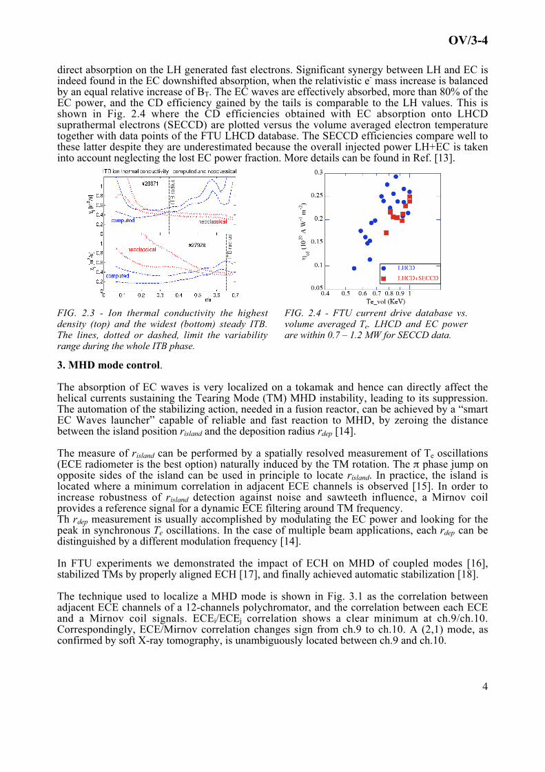
direct absorption on the LH generated fast electrons. Significant synergy between LH and EC isindeed found in the EC downshifted absorption, when the relativistic e- mass increase is balancedby an equal relative increase of BT. The EC waves are effectively absorbed, more than 80% of theEC power, and the CD efficiency gained by the tails is comparable to the LH values. This isshown in Fig. 2.4 where the CD efficiencies obtained with EC absorption onto LHCDsuprathermal electrons (SECCD) are plotted versus the volume averaged electron temperaturetogether with data points of the FTU LHCD database. The SECCD efficiencies compare well tothese latter despite they are underestimated because the overall injected power LH+EC is takeninto account neglecting the lost EC power fraction. More details can be found in Ref. [13].
FIG. 2.3 - Ion thermal conductivity the highestdensity (top) and the widest (bottom) steady ITB.The lines, dotted or dashed, limit the variabilityrange during the whole ITB phase.
FIG. 2.4 - FTU current drive database vs.volume averaged Te. LHCD and EC powerare within 0.7 – 1.2 MW for SECCD data.
3. MHD mode control.
The absorption of EC waves is very localized on a tokamak and hence can directly affect thehelical currents sustaining the Tearing Mode (TM) MHD instability, leading to its suppression.The automation of the stabilizing action, needed in a fusion reactor, can be achieved by a “smartEC Waves launcher” capable of reliable and fast reaction to MHD, by zeroing the distancebetween the island position risland and the deposition radius rdep [14].
The measure of risland can be performed by a spatially resolved measurement of Te oscillations(ECE radiometer is the best option) naturally induced by the TM rotation. The π phase jump onopposite sides of the island can be used in principle to locate risland. In practice, the island islocated where a minimum correlation in adjacent ECE channels is observed [15]. In order toincrease robustness of risland detection against noise and sawteeth influence, a Mirnov coilprovides a reference signal for a dynamic ECE filtering around TM frequency.Th rdep measurement is usually accomplished by modulating the EC power and looking for thepeak in synchronous Te oscillations. In the case of multiple beam applications, each rdep can bedistinguished by a different modulation frequency [14].
In FTU experiments we demonstrated the impact of ECH on MHD of coupled modes [16],stabilized TMs by properly aligned ECH [17], and finally achieved automatic stabilization [18].
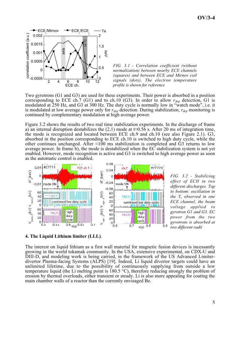
The technique used to localize a MHD mode is shown in Fig. 3.1 as the correlation betweenadjacent ECE channels of a 12-channels polychromator, and the correlation between each ECEand a Mirnov coil signals. ECEi/ECEj correlation shows a clear minimum at ch.9/ch.10.Correspondingly, ECE/Mirnov correlation changes sign from ch.9 to ch.10. A (2,1) mode, asconfirmed by soft X-ray tomography, is unambiguously located between ch.9 and ch.10.
OV/3-4
5
-0.0005
0
0.0005
0.001
0.0015
0.002
0
0.5
1
1.5
2
2 4 6 8 10 12
ECEi/Mirnov ECE
i/ECE
jTe
corr
elat
ion
coef
ficie
nt (
a.u.
)
keV
ECE ch.
axis
(2,1
)
FIG. 3.1 - Correlation coefficient (withoutnormalization) between nearby ECE channels(squares) and between ECE and Mirnov coilsignals (dots). The electron temperatureprofile is shown for reference
Two gyrotrons (G1 and G3) are used for these experiments. Their power is absorbed in a positioncorresponding to ECE ch.7 (G1) and to ch.10 (G3). In order to allow rdep detection, G1 ismodulated at 250 Hz, and G3 at 300 Hz. The duty cycle is normally low in “watch mode”, i.e. itis modulated at low average power only for rdep detection. During stabilization, rdep monitoring iscontinued by complementary modulation at high average power.
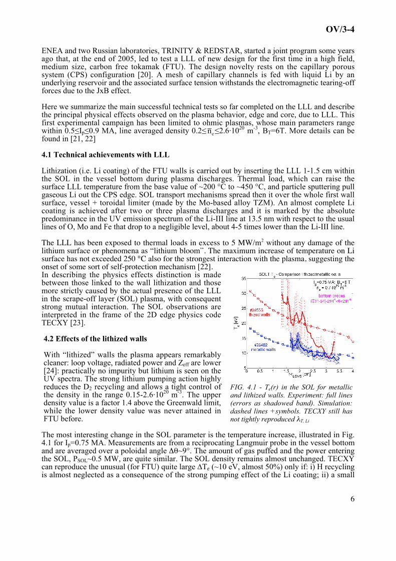
Figure 3.2 shows the results of two real time stabilization experiments. In the discharge of framea) an internal disruption destabilizes the (2,1) mode at t≈0.56 s. After 20 ms of integration time,the mode is recognized and located between ECE ch.9 and ch.10 (see also Figure 2.1). G3,absorbed in the position corresponding to ECE ch.10 is switched to high duty cycle, while theother continues unchanged. After ≈100 ms stabilization is completed and G3 returns to lowaverage power. In frame b), the mode is destabilized when the EC stabilization system is not yetenabled. However, mode recognition is active and G3 is switched to high average power as soonas the automatic control is enabled.
FIG. 3.2 - Stabilizingeffect of ECH in twodifferent discharges. Topto bottom: oscillation inthe Te observed in oneECE channel, the beamvoltage applied togyrotron G1 and G3. ECpower from the twogyrotrons is absorbed attwo different radii
4. The Liquid Lithium limiter (LLL).
The interest on liquid lithium as a first wall material for magnetic fusion devices is incessantlygrowing in the world tokamak community. In the USA, extensive experimental, on CDX-U andDIII-D, and modeling work is being carried, in the framework of the US Advanced Limiter-divertor Plasma-facing Systems (ALPS) [19]. Indeed, Li liquid divertor targets could have anunlimited lifetime, due to the possibility of continuously supplying from outside a lowtemperature liquid (the Li melting point is 180.5 °C), therefore reducing strongly the problem oferosion by thermal overloads, either transient or steady. Li is also more appealing for coating themain chamber walls of a reactor than the currently envisaged Be.
OV/3-4
6
ENEA and two Russian laboratories, TRINITY & REDSTAR, started a joint program some yearsago that, at the end of 2005, led to test a LLL of new design for the first time in a high field,medium size, carbon free tokamak (FTU). The design novelty rests on the capillary poroussystem (CPS) configuration [20]. A mesh of capillary channels is fed with liquid Li by anunderlying reservoir and the associated surface tension withstands the electromagnetic tearing-offforces due to the JxB effect.
Here we summarize the main successful technical tests so far completed on the LLL and describethe principal physical effects observed on the plasma behavior, edge and core, due to LLL. Thisfirst experimental campaign has been limited to ohmic plasmas, whose main parameters rangewithin 0.5≤Ip≤0.9 MA, line averaged density 0.2≤
€
n e≤2.6·1020 m-3, BT=6T. More details can befound in [21, 22]
4.1 Technical achievements with LLL
Lithization (i.e. Li coating) of the FTU walls is carried out by inserting the LLL 1-1.5 cm withinthe SOL in the vessel bottom during plasma discharges. Thermal load, which can raise thesurface LLL temperature from the base value of ~200 °C to ~450 °C, and particle sputtering pullgaseous Li out the CPS edge. SOL transport mechanisms spread then it over the whole first wallsurface, vessel + toroidal limiter (made by the Mo-based alloy TZM). An almost complete Licoating is achieved after two or three plasma discharges and it is marked by the absolutepredominance in the UV emission spectrum of the Li-III line at 13.5 nm with respect to the usuallines of O, Mo and Fe that drop to a negligible level, about 4-5 times lower than the Li-III line.
The LLL has been exposed to thermal loads in excess to 5 MW/m2 without any damage of thelithium surface or phenomena as “lithium bloom”. The maximum increase of temperature on Lisurface has not exceeded 250 °C also for the strongest interaction with the plasma, suggesting theonset of some sort of self-protection mechanism [22].In describing the physics effects distinction is madebetween those linked to the wall lithization and thosemore strictly caused by the actual presence of the LLLin the scrape-off layer (SOL) plasma, with consequentstrong mutual interaction. The SOL observations areinterpreted in the frame of the 2D edge physics codeTECXY [23].
4.2 Effects of the lithized walls
With “lithized” walls the plasma appears remarkablycleaner: loop voltage, radiated power and Zeff are lower[24]: practically no impurity but lithium is seen on theUV spectra. The strong lithium pumping action highlyreduces the D2 recycling and allows a tight control ofthe density in the range 0.15-2.6·1020 m-3. The upperdensity value is a factor 1.4 above the Greenwald limit,while the lower density value was never attained inFTU before.
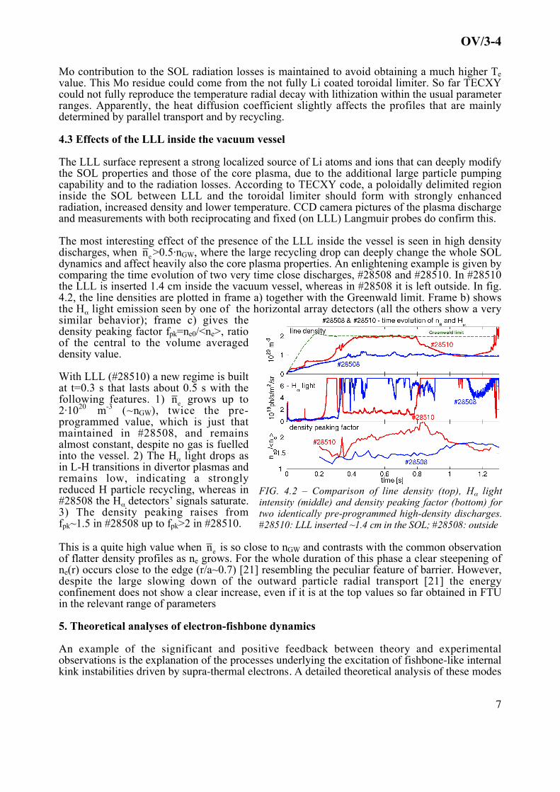
FIG. 4.1 - Te(r) in the SOL for metallicand lithized walls. Experiment: full lines(errors as shadowed band). Simulation:dashed lines +symbols. TECXY still hasnot tightly reproduced λT, Li
The most interesting change in the SOL parameter is the temperature increase, illustrated in Fig.4.1 for Ip=0.75 MA. Measurements are from a reciprocating Langmuir probe in the vessel bottomand are averaged over a poloidal angle Δθ~9°. The amount of gas puffed and the power enteringthe SOL, PSOL~0.5 MW, are quite similar. The SOL density remains almost unchanged. TECXYcan reproduce the unusual (for FTU) quite large ∆Te (~10 eV, almost 50%) only if: i) H recyclingis almost neglected as a consequence of the strong pumping effect of the Li coating; ii) a small
OV/3-4
7
Mo contribution to the SOL radiation losses is maintained to avoid obtaining a much higher Tevalue. This Mo residue could come from the not fully Li coated toroidal limiter. So far TECXYcould not fully reproduce the temperature radial decay with lithization within the usual parameterranges. Apparently, the heat diffusion coefficient slightly affects the profiles that are mainlydetermined by parallel transport and by recycling.
4.3 Effects of the LLL inside the vacuum vessel
The LLL surface represent a strong localized source of Li atoms and ions that can deeply modifythe SOL properties and those of the core plasma, due to the additional large particle pumpingcapability and to the radiation losses. According to TECXY code, a poloidally delimited regioninside the SOL between LLL and the toroidal limiter should form with strongly enhancedradiation, increased density and lower temperature. CCD camera pictures of the plasma dischargeand measurements with both reciprocating and fixed (on LLL) Langmuir probes do confirm this.
The most interesting effect of the presence of the LLL inside the vessel is seen in high densitydischarges, when
€
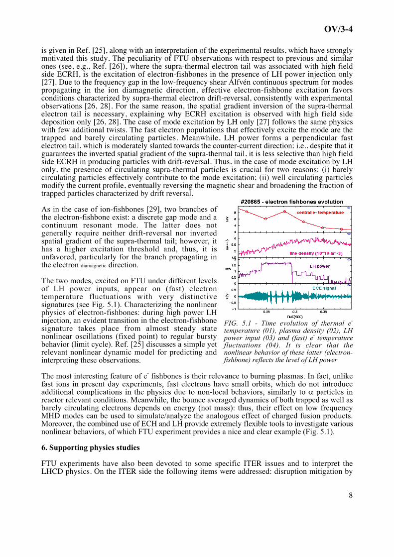
n e >0.5·nGW, where the large recycling drop can deeply change the whole SOLdynamics and affect heavily also the core plasma properties. An enlightening example is given bycomparing the time evolution of two very time close discharges, #28508 and #28510. In #28510the LLL is inserted 1.4 cm inside the vacuum vessel, whereas in #28508 it is left outside. In fig.4.2, the line densities are plotted in frame a) together with the Greenwald limit. Frame b) showsthe Hα light emission seen by one of the horizontal array detectors (all the others show a verysimilar behavior); frame c) gives thedensity peaking factor fpk=ne0/<ne>, ratioof the central to the volume averageddensity value.
With LLL (#28510) a new regime is builtat t=0.3 s that lasts about 0.5 s with thefollowing features. 1)
€
n e grows up to2·1020 m-3 (~nGW), twice the pre-programmed value, which is just thatmaintained in #28508, and remainsalmost constant, despite no gas is fuelledinto the vessel. 2) The Hα light drops asin L-H transitions in divertor plasmas andremains low, indicating a stronglyreduced H particle recycling, whereas in#28508 the Hα detectors’ signals saturate.3) The density peaking raises fromfpk~1.5 in #28508 up to fpk>2 in #28510.
FIG. 4.2 – Comparison of line density (top), Hα lightintensity (middle) and density peaking factor (bottom) fortwo identically pre-programmed high-density discharges.#28510: LLL inserted ~1.4 cm in the SOL; #28508: outside
This is a quite high value when
€
n e is so close to nGW and contrasts with the common observationof flatter density profiles as ne grows. For the whole duration of this phase a clear steepening ofne(r) occurs close to the edge (r/a~0.7) [21] resembling the peculiar feature of barrier. However,despite the large slowing down of the outward particle radial transport [21] the energyconfinement does not show a clear increase, even if it is at the top values so far obtained in FTUin the relevant range of parameters
5. Theoretical analyses of electron-fishbone dynamics
An example of the significant and positive feedback between theory and experimentalobservations is the explanation of the processes underlying the excitation of fishbone-like internalkink instabilities driven by supra-thermal electrons. A detailed theoretical analysis of these modes
OV/3-4
8
is given in Ref. [25], along with an interpretation of the experimental results, which have stronglymotivated this study. The peculiarity of FTU observations with respect to previous and similarones (see, e.g., Ref. [26]), where the supra-thermal electron tail was associated with high fieldside ECRH, is the excitation of electron-fishbones in the presence of LH power injection only[27]. Due to the frequency gap in the low-frequency shear Alfvén continuous spectrum for modespropagating in the ion diamagnetic direction, effective electron-fishbone excitation favorsconditions characterized by supra-thermal electron drift-reversal, consistently with experimentalobservations [26, 28]. For the same reason, the spatial gradient inversion of the supra-thermalelectron tail is necessary, explaining why ECRH excitation is observed with high field sidedeposition only [26, 28]. The case of mode excitation by LH only [27] follows the same physicswith few additional twists. The fast electron populations that effectively excite the mode are thetrapped and barely circulating particles. Meanwhile, LH power forms a perpendicular fastelectron tail, which is moderately slanted towards the counter-current direction; i.e., despite that itguarantees the inverted spatial gradient of the supra-thermal tail, it is less selective than high fieldside ECRH in producing particles with drift-reversal. Thus, in the case of mode excitation by LHonly, the presence of circulating supra-thermal particles is crucial for two reasons: (i) barelycirculating particles effectively contribute to the mode excitation; (ii) well circulating particlesmodify the current profile, eventually reversing the magnetic shear and broadening the fraction oftrapped particles characterized by drift reversal.
As in the case of ion-fishbones [29], two branches ofthe electron-fishbone exist: a discrete gap mode and acontinuum resonant mode. The latter does notgenerally require neither drift-reversal nor invertedspatial gradient of the supra-thermal tail; however, ithas a higher excitation threshold and, thus, it isunfavored, particularly for the branch propagating inthe electron diamagnetic direction.
The two modes, excited on FTU under different levelsof LH power inputs, appear on (fast) electrontemperature fluctuations with very distinctivesignatures (see Fig. 5.1). Characterizing the nonlinearphysics of electron-fishbones: during high power LHinjection, an evident transition in the electron-fishbonesignature takes place from almost steady statenonlinear oscillations (fixed point) to regular burstybehavior (limit cycle). Ref. [25] discusses a simple yetrelevant nonlinear dynamic model for predicting andinterpreting these observations.
FIG. 5.1 - Time evolution of thermal e-
temperature (01), plasma density (02), LHpower input (03) and (fast) e- temperaturefluctuations (04). It is clear that thenonlinear behavior of these latter (electron-fishbone) reflects the level of LH power
The most interesting feature of e- fishbones is their relevance to burning plasmas. In fact, unlikefast ions in present day experiments, fast electrons have small orbits, which do not introduceadditional complications in the physics due to non-local behaviors, similarly to α particles inreactor relevant conditions. Meanwhile, the bounce averaged dynamics of both trapped as well asbarely circulating electrons depends on energy (not mass): thus, their effect on low frequencyMHD modes can be used to simulate/analyze the analogous effect of charged fusion products.Moreover, the combined use of ECH and LH provide extremely flexible tools to investigate variousnonlinear behaviors, of which FTU experiment provides a nice and clear example (Fig. 5.1).
6. Supporting physics studies
FTU experiments have also been devoted to some specific ITER issues and to interpret theLHCD physics. On the ITER side the following items were addressed: disruption mitigation by
OV/3-4
9
means of EC power, study of disruptions during LH, and reliability analysis of the microwave(140 GHz) collective Thomson scattering (CTS) diagnostic in the configuration proposed forITER. On the LHCD side the statistical analysis of the CD efficiency has been performed and themodeling of linear and non-linear interaction of the LH waves with the edge plasma has beenstarted.
6.1. Disruption mitigation with ECH and LH disruptions
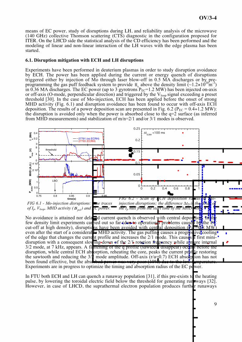
Experiments have been performed in deuterium plasmas in order to study disruption avoidanceby ECH. The power has been applied during the current or energy quench of disruptionstriggered either by injection of Mo through laser blow-off in 0.5 MA discharges or by pre-programming the gas puff feedback system to provide
€
n e above the density limit (~1.2×10²⁰m-3)in 0.36 MA discharges. The EC power (up to 3 gyrotrons PEC=1.2 MW) has been injected on-axisor off-axis (O-mode, perpendicular direction) and triggered by the Vloop signal exceeding a presetthreshold [30]. In the case of Mo-injection, ECH has been applied before the onset of strongMHD activity (Fig. 6.1) and disruption avoidance has been found to occur with off-axis ECHdeposition. The results of a power deposition scan are presented in Fig. 6.2 (PEC = 0.4÷1.2 MW):the disruption is avoided only when the power is absorbed close to the q=2 surface (as inferredfrom MHD measurements) and stabilization of m/n=2/1 and/or 3/1 modes is observed.
0
0.2
0.4
27791 (no ECRH)27793 (ECRH)I p
(M
A)
0
4
8
Vlo
op (
V) threshold
0
2 105
4 105
MH
D (
A.U
.)
0
0.5
1
0.75 0.8 0.85 0.9 0.95
PE
CR
H (
MW
)
time(s)
LBO
FIG 6.1 - Mo-injection disruptions: time tracesof Ip, Vloop, MHD activity (
€
˜ ˙ B pol ) and EC power.
0
0.05
0.1
0.15
0.2
0.25
0 0.2 0.4 0.6 0.8 1
Δt D (
s)
ρdep
ΔtECRH
<100 ms
FIG 6.2 - Scan of ECH deposition radius in Mo-injection disruptions; the difference ∆tD is the delay ofthe Ip null from the start time of the MHD mode
No avoidance is attained nor delayed current quench is observed with central deposition. In thefew density limit experiments carried out so far (due to operational problems caused by the ECcut-off at high density), disruptions have been avoided with central deposition (PEC=0.8 MW)even after the start of a considerable MHD activity. The gas puffing causes a progressive coolingof the edge that changes the current profile and increases the 2/1 mode. This causes a first mini-disruption with a consequent slowing down of the 2/1 rotation frequency while a more internal3/2 mode, at 7 kHz, appears. A flattening of the q profile (sawteeth disappear) occurs before thedisruption, while central ECH absorption, reheating the core, peaks the current profile restoringthe sawtooth and reducing the 3/2 mode amplitude. Off-axis (r/a=0.7) ECH absorption has notbeen found effective, but the absorbed power was very poor (10%) due to the low temperature.Experiments are in progress to optimize the timing and absorption radius of the EC power.
In FTU both ECH and LH can quench a runaway population [31], if this pre-exists to the heatingpulse, by lowering the toroidal electric field below the threshold for generating runaways [32].However, in case of LHCD, the suprathermal electron population produces further runaways
OV/3-4
10
once LHCD is over (if plasma conditions allow it) due to acceleration by the restored electricfield. In a similar way, in disruptions occurring during LHCD, large runaway currents (up to 80%of the pre-disruption Ip) can be produced. The largest runaway currents correspond to the slowestcurrent decay rates. This is consistent with the acceleration of pre-existing LH-generatedsuprathermal electrons during the disruption current quench [33], while cannot be explainedthrough the Dreicer and avalanche mechanisms of electron thermal runaway generation. Suchresults can be relevant for the operation of ITER whenever LH power is used.
6.2. Collective Thomson Scattering (CTS) diagnostic studies
The ITER relevance of the CTS experiment in FTU lays in the wave propagation at frequencybelow gyro-resonance, fgyr=140 GHz, 195≤fEC≤220 GHz. Indeed, a recent feasibility study [34]clearly stated that the diagnostic of the confined alphas in ITER based on mm-wave CTS requiresfgyr=50-60 GHz, with propagation in the X-mode, with fec,ITER~151 GHz (BT0,ITER~5.4T).Interesting results followed the unambiguous interpretation in 2006 of strongly anomalous non-thermal spectra systematically observed. Here we limit to summarize the most relevant facts,while a dedicated paper on the subject is being published [35].
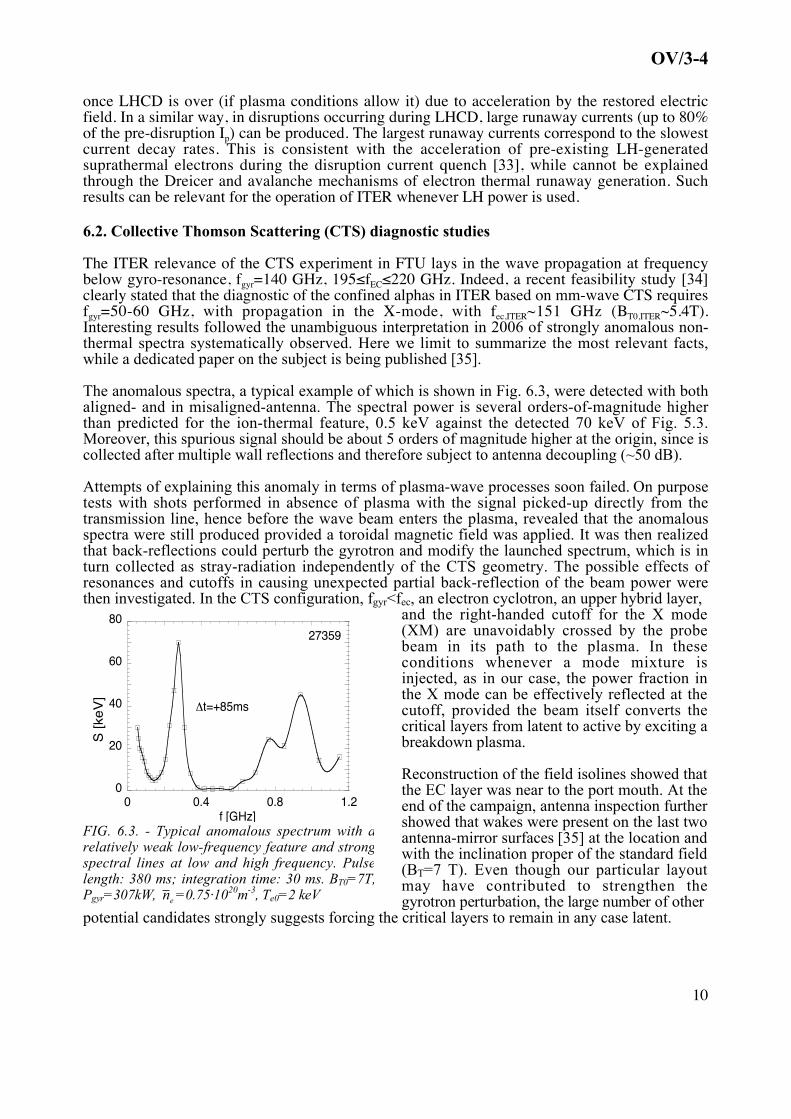
The anomalous spectra, a typical example of which is shown in Fig. 6.3, were detected with bothaligned- and in misaligned-antenna. The spectral power is several orders-of-magnitude higherthan predicted for the ion-thermal feature, 0.5 keV against the detected 70 keV of Fig. 5.3.Moreover, this spurious signal should be about 5 orders of magnitude higher at the origin, since iscollected after multiple wall reflections and therefore subject to antenna decoupling (~50 dB).
Attempts of explaining this anomaly in terms of plasma-wave processes soon failed. On purposetests with shots performed in absence of plasma with the signal picked-up directly from thetransmission line, hence before the wave beam enters the plasma, revealed that the anomalousspectra were still produced provided a toroidal magnetic field was applied. It was then realizedthat back-reflections could perturb the gyrotron and modify the launched spectrum, which is inturn collected as stray-radiation independently of the CTS geometry. The possible effects ofresonances and cutoffs in causing unexpected partial back-reflection of the beam power werethen investigated. In the CTS configuration, fgyr<fec, an electron cyclotron, an upper hybrid layer,
0
20
40
60
80
0 0.4 0.8 1.2
S [k
eV]
Δt=+85ms
f [GHz]
27359
FIG. 6.3. - Typical anomalous spectrum with arelatively weak low-frequency feature and strongspectral lines at low and high frequency. Pulselength: 380 ms; integration time: 30 ms. BT0=7T,Pgyr=307kW,
€
n e =0.75·1020m-3, Te0=2 keV
and the right-handed cutoff for the X mode(XM) are unavoidably crossed by the probebeam in its path to the plasma. In theseconditions whenever a mode mixture isinjected, as in our case, the power fraction inthe X mode can be effectively reflected at thecutoff, provided the beam itself converts thecritical layers from latent to active by exciting abreakdown plasma.
Reconstruction of the field isolines showed thatthe EC layer was near to the port mouth. At theend of the campaign, antenna inspection furthershowed that wakes were present on the last twoantenna-mirror surfaces [35] at the location andwith the inclination proper of the standard field(BT=7 T). Even though our particular layoutmay have contributed to strengthen thegyrotron perturbation, the large number of other
potential candidates strongly suggests forcing the critical layers to remain in any case latent.
OV/3-4
11
The most viable of the solutions considered so far seems a remote-steering antenna (RSA) [36]with a vacuum tight ceramic (or diamond) window at its mouth on the plasma side. A RSA ofspecial interest for CTS in FTU was fruitfully tested in ECCD experiments on TRIAM-1M [37].
Considering the MW power level at which the ITER diagnostics will be operated, the constraintson the CTS antennas indicated by our results and the positive indications they provide in thisrespect quite straightforwardly extend to the perspective of α particle CTS in ITER.
6.3 Physics study of LH propagation
The analysis of the whole FTU data set on the LHCD efficiency, ηCD, has pointed out importantparametric dependences on the major plasma parameters. The physical reasons for theexperimental spread close to a factor 3 in the ηCD values have been recognized [38]. The maincauses have been identified in the modifications suffered by the N|| (parallel index of refraction)spectrum along the ray trajectory before the power is absorbed. The effect of the densityfluctuations inside the edge turbulent layer crossed by the LH rays has been stressed beingprimarily of linear nature. However, also the presence of non-linear interactions should beconsidered, mainly those causing parametric decay instabilities (PDI) in the low frequencyacoustic range and consequently modifying the N|| spectrum entering the core. A numerical code,Lhstar on purpose recently developed [39], models the LH wave absorption in a tokamak, whenedge PDI can grow. The N|| spectral broadening occurring at the edge provides the bridge overthe spectral gap necessary for absorbing effectively the LH power in the core, though it affects asmall fraction of the power (~10%). The effect of the toroidicity in the main plasma is retainedand, the ray tracing and the Fokker-Planck analyses are performed in parallel and consistently ateach radial step of the calculation, for each ray. The calculated absorption profiles for JET areconsistent with the measured q profiles [40].
7. Perspectives
A priority of the next FTU experimental campaigns will be the full testing of the liquid lithiumlimiter under strong additional heating (LH+ECH) and surface thermal load in excess of 10MW/m2. The stability of the liquid surface against disruption will also be assessed, and the newhigh density / high particle confinement regimes will be characterized in more detail. The studyof ITB physics will be mainly focused on the ion transport under greater collisional coupling toelectrons, by exploiting the full capability of the auxiliary heating systems in order to decreasethe ratio τei,th/τE, between the thermal e--i+ equipartition time and the energy confinement time, sofar always larger than 5. This will be carried out mainly increasing density in discharges withplasma current Ip≥0.5 MA. The full automation and a complete feedback loop in the MHDstabilization by local ECCD is also in the future plans, as well as the restart of the IBW (ionBernstein wave) radiofrequency system (PIBW≤0.5 MW, fIBW=433 MHz) for possibly inducingdirectly a poloidal velocity shear in the core plasma (r/a~0.5). Full exploitation of the recentlyinstalled motional Stark effect + charge exchange recombination spectroscopy diagnostic willprovide essential information on the ion temperature and plasma current radial profiles. On theside of support to ITER issues, it is planned to investigate deeply the promising capabilities ofECH+LHCD systems in assisting the plasma start-up, to optimize disruption mitigation by ECHand to study more systematically the effect of LH on disruptions. The possibility of testing a newlaunching/ receiving antenna for the collective Thomson scattering is also being considered.
References [1] Special Issue on FTU Fus. Sci. Techn. (Guest editor C. Gormezano) V. 45 (May 2004)[2] B. Angelini et al., Nucl. Fusion, V. 45 (2005) p. S227-S238[3] S. M. Kaye et al., Nucl. Fusion, V. 37 (1997) p. 1303
OV/3-4
12
[4] M. J. Greenwald et al., Nucl. Fusion, V. 28 (1988) p. 2199[5] V. Pericoli Ridolfini et al., 21st Fusion Energy Conf., Chengdu-China (2006), paper EX/P1-15[6] V. Pericoli Ridolfini et al., Plasma Phys. Control. Fusion, V. 47 (2005) p. B285–B301[7] C. Gormezano et al., Plasma Phys. Control. Fusion, V. 46 (2004) p. B435–B447[8] J. Mailloux et al., Phys. Plasmas, V. 9 No. 3, p. 2156-2164 (2002)[9] S. Ide et al., Nucl. Fusion, V. 40, p. 445-451 (2000)[10] V. Pericoli Ridolfini et al., Nucl. Fusion, V. 43 (2003) p. 469–478[11] C. Sozzi, et al. Journal of Physics: Conference Series, V. 25 (2005) p.198–209[12] M. De Benedetti et al., 32nd EPS Conf. Tarragona (2005), Europh. Conf. Abs., V. 29C, P4.035[13] G. Granucci et al., “Application of ECRH/ECCD on FTU: an Overview of Recent Results”,
invited paper at 14th Workshop on ECE and ECRH, Santorini (Gr), 9-11 May 2006[14] S. Cirant et al., Journal of Physics: Conference Series, V. 25 (2005) 223–233[15] J. Berrino et al., Nucl. Fusion, V. 45 No 11 (November 2005) 1350-1361[16] E. Lazzaro et al., Phys. Rev. Lett. V. 84, 6038 (2000)[17] S. Cirant et al. 18th Fusion Energy Conf., Sorrento, Italy, (2000) paper EX3/3[18] E. Lazzaro et al., 6th International Workshop "Strong Microwaves in Plasmas", Nizhny
Novgorod, Russia, 2005[19] J.N. Brooks et al., Fusion Science and Technology, V. 47, (2005) 669-677[20] V.A. Evtikhin, I.E. Lyublinski, et al., Fusion Eng. Des., V. 56-57 (2001) 363-367[21] V. Pericoli Ridolfini et al., “Edge properties with the liquid lithium limiter in FTU -
experiment and transport modelling”, submitted to PPCF.[22] M.L. Apicella et al., “First experiments with lithium limiter on FTU”, 17th PSI Int. Conf.
Hefei, Anhui, China, 22-26 May 2006, to be published in J. Nucl. Mat.[23] R. Zagórski, H. Gerhauser, Physica Scripta, V. 70, Part 2/3, (2004) 173[24] G. Mazzitelli et al., 21st Fusion Energy Conf., Chengdu-China (2006), paper EX/P4-16[25] F. Zonca et al., 21st Fusion Energy Conf., Chengdu-China (2006), paper TH/3-2[26] K.L. Wong, et al., Phys. Rev. Lett., V. 85 (2000) 996[27] P. Smeulders et al., 29th EPS Conf., Montreux, Europh. Conf. Abs. V. 26B (2002) D-5.016[28] X.T. Ding et al., Nucl. Fusion, V. 42 (2002) 491[29] L. Chen et al., Phys. Rev. Lett., V. 52 (1984) 1122[30] B. Esposito et al., 33rd EPS Conf., Roma, Italy, Europh. Conf. Abs. (2006) V. 30I, P5.071[31] J.R. Martin-Solis et al., Nucl. Fusion, V. 45 (2005) 1524[32] J.R. Martin-Solis et al., Nucl. Fusion, V. 44 (2004) 974[33] J.R. Martin-Solis et al., "Enhanced production of runaway electrons during disruptive
termination of discharges heated with lower hybrid power in the Frascati TokamakUpgrade", accepted for publication in Phys. Rev. Lett. (2006)
[34] H. Bindslev et al., “ITER Fast Ion Collective Thomson Scattering – Feasibility Study”,Annex 1, Riso Lab. Report, EFDA Contract 01.654, November 2003
[35] U. Tartari et al., Nucl. Fusion, V. 46 (2006) 928 940.[36] R. Prater et al. 10th Joint Workshop on ECE and CRH, Ameland (The Netherlands, 1997),
Word Scientific, ISBN 981-02-3219-5, 531-540[37] H. Idei et al., Nucl. Fusion V. 46 (2006) 489[38] V. Pericoli Ridolfini et al., Nucl Fusion , V. 45 (2005) , p. 1386-1395[39] R. Cesario et al., Phys. Rev. Lett., V. 92 , p. 175002-1-175002-4 (2004)[40] C. Castaldo et al., 33rd EPS Conf., Roma, Italy (2006), Europh. Conf. Abs., V. 30I, P1.122