ov 3 - 1 copyright © 2013 logical operations, inc. all rights reserved. network media and hardware ...
TRANSCRIPT

OV 3 - 1Copyright © 2013 Logical Operations, Inc. All rights reserved.
Network Media and Hardware
Bounded Network Media Unbounded Network Media Noise Control Network Connectivity Devices

OV 3 - 2Copyright © 2013 Logical Operations, Inc. All rights reserved.
Network Media
Bounded mediaBounded media
Unbounded mediaUnbounded media

OV 3 - 3Copyright © 2013 Logical Operations, Inc. All rights reserved.
Copper Media
A type of bounded media Uses copper conductors surrounded by insulated coating Conductors - solid wire or from braided strands of wire Shielding wrapped around conductors

OV 3 - 4Copyright © 2013 Logical Operations, Inc. All rights reserved.
Twisted Pair Cables
Primary wires are striped
Primary wires are striped
Multiple wires enclosed in a
sheath
Multiple wires enclosed in a
sheath
Primary and secondary wiresPrimary and secondary wires

OV 3 - 5Copyright © 2013 Logical Operations, Inc. All rights reserved.
Twisted Pair Cable Types
Cable Type Description
UTP
Characteristics of UTP are:Does not include shielding around its conductorsContains four pairs of stranded or solid conductorsInexpensive and reliableSupports transmission distances of up to 100 metersSupports data transfer rates of up to 1 Gbps
STP
Characteristics of STP are:Includes foil wrapper shielding around its conductors Contains four pairs of stranded or solid conductorsMore expensive than UTPSupports distances up to 100 metersSupports data transfer rates of 10 to 100 Mbps

OV 3 - 6Copyright © 2013 Logical Operations, Inc. All rights reserved.
Twisted Pair Cable Categories
Category Specification
1 Network Type: Voice transmission, not suitable for data networking Maximum speed: 1 Mbps
2 Network Type: Digital telephone and low-speed data networks Maximum speed: 4 Mbps
3
Network Type: Ethernet Maximum speed: 10 Mbps CAT 3 is currently used for telephone wiring
4
Network Type: IBM Token Ring Maximum speed: 16 Mbps CAT 4 may also be used for 10 Mbps Ethernet

OV 3 - 7Copyright © 2013 Logical Operations, Inc. All rights reserved.
Twisted Pair Cable Categories (Cont.)
Category Specification
5 Network Type: Fast Ethernet Maximum speed: CAT 5 supports a signaling rate of 100 Mbps
5e Network Type: Gigabit Ethernet Maximum speed: CAT 5e supports a signaling rate of 350 Mbps
6
Network Type: Gigabit Ethernet Maximum speed: 1 Gbps CAT 6 supports a signaling rate of 250 MHz
7
Network Type: Gigabit Ethernet Maximum speed: 1 Gbps+ CAT 7 supports a signaling rate of 1 Ghz

OV 3 - 8Copyright © 2013 Logical Operations, Inc. All rights reserved.
Coaxial Cables
Braided shieldingBraided shielding
Single copper conductor
Single copper conductor
Non-conductiveinsulated coating Non-conductive
insulated coating

OV 3 - 9Copyright © 2013 Logical Operations, Inc. All rights reserved.
Coaxial Cable Types
Cable Type Characteristic
R58/U 5 mm (0.25 inch) coax cable with solid core and 50 ohms impedance Used for Ethernet networking
RG58A/U
5 mm (0.25 inch) coax cable with stranded core and 50 ohms impedance
Used for Ethernet networking
RG8 10 mm (0.5 inch) coax cable with solid core and 50 ohms impedance Used for Ethernet networking
RG9
10 mm (0.5 inch) coax cable with stranded core and 51 ohms impedance
Used for cable television transmission and cable modems
RG62 5 mm (0.25 inch) coax cable with solid core and 93 ohms impedance Used for ARCNET networking
RG59 6 mm (0.24 inch) coax cable with 75 ohms impedance Used for low-power video connections such as digital receivers
RG6
Coax cable with 75 ohms impedance Most often used in routing cable television signals Preferred over RG59

OV 3 - 10Copyright © 2013 Logical Operations, Inc. All rights reserved.
Coaxial Connector Types
Connector Type Characteristic
F
Coax connector type used with 75-ohm cable to connect cable TV and FM antenna cables
Comes in a secure screw-on form or as a non-threaded slip-on connector
BNC
Cable connector used to terminate a coaxial cable Used with the RG58/U cable Has a center pin connected to the center cable conductor and a
metal tube connected to the shield of cable Rotating ring outside metal tube locks cable to connector. The types of BNC connectors include:
T-connector Barrel connector Terminator

OV 3 - 11Copyright © 2013 Logical Operations, Inc. All rights reserved.
Network Media Performance Factors
Factor Description
Noise
Electromagnetic interference disrupting the signal Signal to noise ratio decreases as transmitting distance
increases
Attentuation
Progressive degradation of a signal as it travels across a network medium
Caused by increase of noise or decrease in signal strength Susceptibility to noise and attenuation depends on media types
used Occurs when cable length exceeds length up to which signals
can travel without distortion
Impedance Opposition to flow of electricity in an AC circuit Measured in ohms (Ω)
OV 3 - 12Copyright © 2013 Logical Operations, Inc. All rights reserved.
Media Converters
Enables networks running on different media to interconnect and exchange signals
To install a media converter: Connect terminated ends of the two media to bridge to converter May need to provide electrical power to the converter

OV 3 - 13Copyright © 2013 Logical Operations, Inc. All rights reserved.
Media Converters (Cont.)
Converter Type Description
Multimode fiber to Ethernet
Used to extend an Ethernet network connection over a multimode fiber backbone
Similar in appearance to BNC connectors
Fiber to Coaxial Used to convert signals on fiber to coaxial cable
Singlemode to multimode fiber
Used to transmit multimode fiber signals over singlemode fiber devices and links
Supports conversion between multimode segments on a network that spans a wider coverage area
OV 3 - 14Copyright © 2013 Logical Operations, Inc. All rights reserved.
Structured Cabling
Is based on 568 Commercial Building Telecommunication Cabling standard developed by Telecommunications Industry Association (TIA) and Electronic Industries Association (EIA) The cabling standard defines regulations on designing, building, and managing a cabling
system utilizing structured cabling according to specified performance characteristics to create a system of unified communications
Is based on hierarchical design that divides cabling into six subsystems

OV 3 - 15Copyright © 2013 Logical Operations, Inc. All rights reserved.
Structured Cabling (Cont.)
Subsystem Description
Entrance facilities
Contains telecommunication service entrance to the building, campus-wide backbone connections, and interconnection to local exchange carrier's telecommunication facilities
Network demarcation point one foot away from where the carrier's facilities enter the building
Carrier designates a different measurement, depending on the needs of facility
Backbone wiring
Provides connections between equipment rooms and telecommunication closets
Runs through floors of building via risers or across campus Allowed distance measurements depend on cable type and
facilities that it connects to
Equipment room
Provides main cross-connection point for an entire facility Provides termination point for backbone wiring connected to
telecommunication closets

OV 3 - 16Copyright © 2013 Logical Operations, Inc. All rights reserved.
Structured Cabling (Cont.)
Subsystem Description
Telecommunications closet
Houses connection equipment for cross-connection to an equipment room with workstations
Contains horizontal wiring connections, and entrance facility connections Can be as many telecommunications closets as needed in an office building
Horizontal wiring
Runs from each workstation outlet to telecommunication closet Maximum allowed distance from outlet to closet is 295 feet Additional 20 feet allowed if patch cables are used, but combined length cannot
be more than 33 feet Specifications include:
Four-pair 100 ohms UTP cable Two-fiber 62.5/125 mm fiber-optic cable Multimode 50/125 mm multimode fiber-optic cable
Work area Consists of wallboxes and faceplates, connectors, and wiring Required that a data and voice outlet be available at each wallbox and faceplate

OV 3 - 17Copyright © 2013 Logical Operations, Inc. All rights reserved.
Premise Wiring
A hierarchical cable system architecture in which a Main Cross-Connect (MCC) is connected via a star topology across backbone cabling to Intermediate Cross-Connects (ICC) and Horizontal Cross-Connects (HCC)
Cross-connects of premise wiring are referred by nonstandard terms as distribution frames, Main Distribution Frames (MDFs), Intermediate Distribution Frames (IDFs), and wiring closets
OV 3 - 18Copyright © 2013 Logical Operations, Inc. All rights reserved.
Premise Wiring (Cont.)
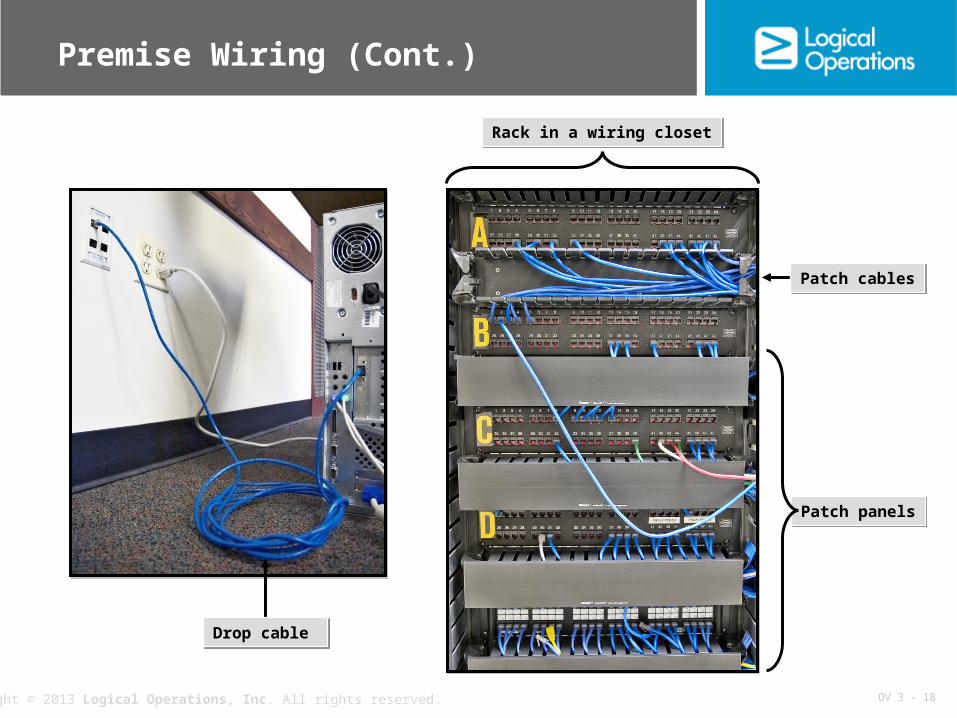
Rack in a wiring closetRack in a wiring closet
Drop cable Drop cable
Patch cablesPatch cables
Patch panelsPatch panels

OV 3 - 19Copyright © 2013 Logical Operations, Inc. All rights reserved.
Plenum and PVC Cables
Plenum cable: Is a network cable jacketed tightly around conductors so that fire cannot travel
within the cable Cable jacket does not emanate poisonous gases when burned Fire codes require installation of this special grade cabling in the plenum Can run through the plenum and firebreak walls
PVC cable: Refered to as non-plenum cable Is inexpensive and flexible Emanate poisonous gases when burned PVC jacketing is not formed tightly to the conductors Allow fire to travel through it

OV 3 - 20Copyright © 2013 Logical Operations, Inc. All rights reserved.
Plenum and PVC Cables (Cont.)

OV 3 - 21Copyright © 2013 Logical Operations, Inc. All rights reserved.
Fiber Optic Cables
Strengthening fibers
Strengthening fibers
Reflective cladding and bufferReflective cladding and bufferOuter jacketOuter jacket
Glass or plastic strands
Glass or plastic strands
CoreCore

OV 3 - 22Copyright © 2013 Logical Operations, Inc. All rights reserved.
Fiber Optic Cable Modes
There are two modes of fiber optic cables: single mode and multimode Both modes of cables have outer diameter of 125 microns Multimode
Light travels through its core in multiple rays or modes Core of 50 or 62.5 microns
Singlemode features Diameter of 9 microns Light travels unidirectionally within the cable Used with laser for telephony and cable TV transmission

OV 3 - 23Copyright © 2013 Logical Operations, Inc. All rights reserved.
Fiber Optic Cable Modes (Cont.)
Fiber Optic Cable Mode
Description
Singlemode fiber
Carries an optical signal through a small core, allowing only a single beam of light to pass
A laser, operating in the infrared portion of the spectrum, is modulated in intensity to transmit the signal through the fiber
Provides bandwidth of up to 30 MHz
Step-index multimode fiber
Contains a core surrounded by cladding When light from the core enters the cladding, a “step down”
occurs due to difference in refractive indices Uses total internal reflection to trap light
Graded index multimode fiber
Possesses variations in the core glass Provides up to 2 GHz of bandwidth

OV 3 - 24Copyright © 2013 Logical Operations, Inc. All rights reserved.
Fiber Connectors
Fiber Optic Connector
Description
Straight Tip (ST)
Similar in appearance to BNC connectors Used to connect multimode fibers Has a straight, ceramic center pin and bayonet lug lockdown Often used in network patch panels A popular type of fiber connector
Subscriber Connector or Standard Connector (SC)
Box-shaped connectors that snap into a receptacle Often used in a duplex configuration Used with a singlemode fiber
Face Contact (FC)
Use a heavy duty ferrule in the center Ferrule-tubular structure made of ceramic or metal that
supports the fiber Are more popular in industrial settings
FDDI
Used for multimode fiber optic cable Are a push/pull-type, two-channel snap-fit connectors Also called Media Interface Connector (MIC)
OV 3 - 25Copyright © 2013 Logical Operations, Inc. All rights reserved.
Fiber Connectors (Cont.)
Fiber Optic Connector
Description
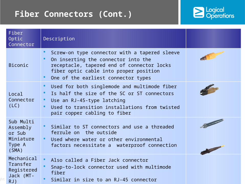
Biconic
Screw-on type connector with a tapered sleeve On inserting the connector into the receptacle, tapered end of
connector locks fiber optic cable into proper position One of the earliest connector types
Local Connector (LC)
Used for both singlemode and multimode fiber Is half the size of the SC or ST connectors Use an RJ-45-type latching Used to transition installations from twisted pair copper
cabling to fiber
Sub Multi Assembly or Sub Miniature Type A (SMA)
Similar to ST connectors and use a threaded ferrule on the outside
Used where water or other environmental factors necessitate a waterproof connection
Mechanical Transfer Registered Jack (MT-RJ)
Also called a Fiber Jack connector Snap-to-lock connector used with multimode fiber Similar in size to an RJ-45 connector
OV 3 - 26Copyright © 2013 Logical Operations, Inc. All rights reserved.
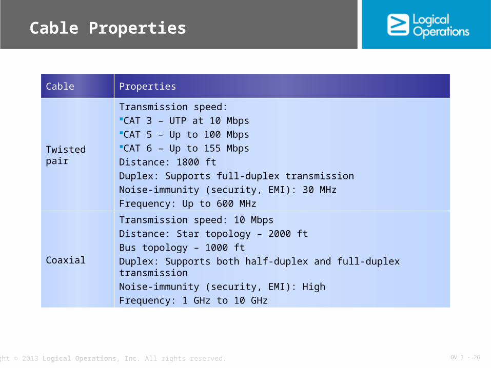
Cable Properties
Cable Properties
Twisted pair
Transmission speed:CAT 3 – UTP at 10 MbpsCAT 5 – Up to 100 MbpsCAT 6 – Up to 155 Mbps
Distance: 1800 ft
Duplex: Supports full-duplex transmission
Noise-immunity (security, EMI): 30 MHz
Frequency: Up to 600 MHz
Coaxial
Transmission speed: 10 Mbps
Distance: Star topology – 2000 ft
Bus topology – 1000 ft
Duplex: Supports both half-duplex and full-duplex transmission
Noise-immunity (security, EMI): High
Frequency: 1 GHz to 10 GHz
OV 3 - 27Copyright © 2013 Logical Operations, Inc. All rights reserved.
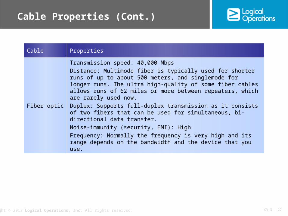
Cable Properties (Cont.)
Cable Properties
Fiber optic
Transmission speed: 40,000 Mbps
Distance: Multimode fiber is typically used for shorter runs of up to about 500 meters, and singlemode for longer runs. The ultra high-quality of some fiber cables allows runs of 62 miles or more between repeaters, which are rarely used now.
Duplex: Supports full-duplex transmission as it consists of two fibers that can be used for simultaneous, bi-directional data transfer.
Noise-immunity (security, EMI): High
Frequency: Normally the frequency is very high and its range depends on the bandwidth and the device that you use.

OV 3 - 28Copyright © 2013 Logical Operations, Inc. All rights reserved.
Other Cable Media Types
Cable Type Description
Serial cable
Type of bounded network media that transfers information between two devices using serial transmission
Information sent one bit at a time in a specific sequence Uses an RS-232 connector In networking, used to connect routers Null modem serial cables used by networking professionals
IEEE 1394 (FireWire™)
It is commonly known as FireWire Used to connect up to 63 devices to form a small local network Cables use a shielded cable similar to STP with either four or six
conductors Connections to devices made with either a six- or four-pin
connector
USB
A personal computer connection to connect multiple peripherals to a single port
Support two-way communications

OV 3 - 29Copyright © 2013 Logical Operations, Inc. All rights reserved.
Wireless Communication
Signals are transmitted over a distance without the use of a physical medium
Signals are transmitted over a distance without the use of a physical medium

OV 3 - 30Copyright © 2013 Logical Operations, Inc. All rights reserved.
Radio Networking
Signals are sent via RF waves
Signals are sent via RF waves
OV 3 - 31Copyright © 2013 Logical Operations, Inc. All rights reserved.
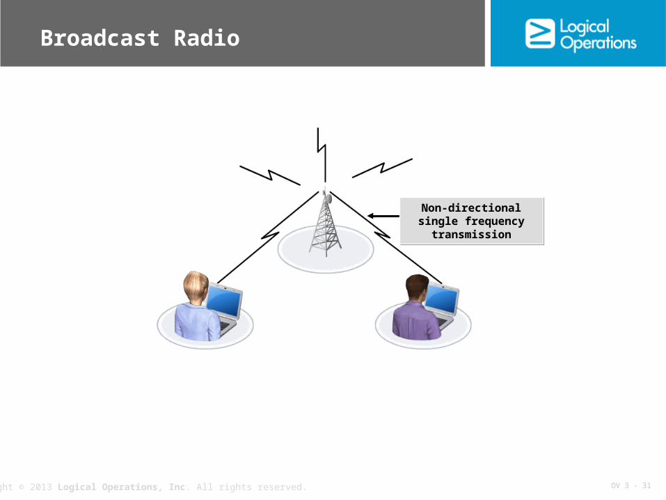
Broadcast Radio
Non-directional single frequency transmissionNon-directional single
frequency transmission

OV 3 - 32Copyright © 2013 Logical Operations, Inc. All rights reserved.
Spread Spectrum
Signal is sent over more than one frequency
Signal is sent over more than one frequency
OV 3 - 33Copyright © 2013 Logical Operations, Inc. All rights reserved.
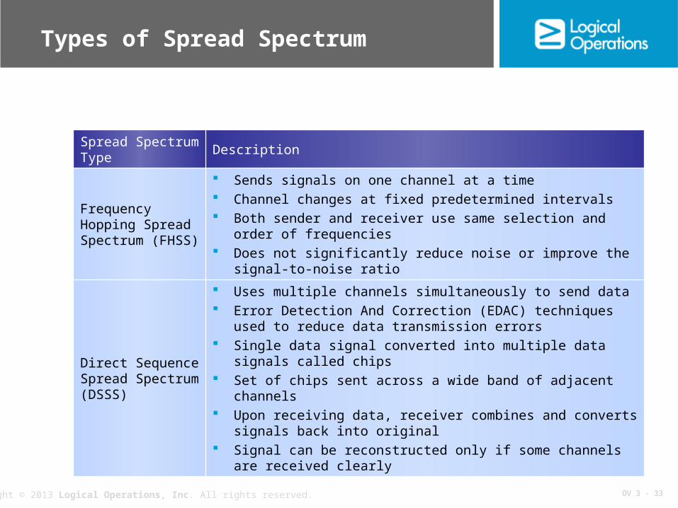
Types of Spread Spectrum
Spread Spectrum Type
Description
Frequency Hopping Spread Spectrum (FHSS)
Sends signals on one channel at a time Channel changes at fixed predetermined intervals Both sender and receiver use same selection and order of
frequencies Does not significantly reduce noise or improve the signal-to-noise
ratio
Direct Sequence Spread Spectrum (DSSS)
Uses multiple channels simultaneously to send data Error Detection And Correction (EDAC) techniques used to reduce
data transmission errors Single data signal converted into multiple data signals called chips Set of chips sent across a wide band of adjacent channels Upon receiving data, receiver combines and converts signals back
into original Signal can be reconstructed only if some channels are received
clearly

OV 3 - 34Copyright © 2013 Logical Operations, Inc. All rights reserved.
Infrared Transmission
Receiver
Needs an unobstructed view of the sender to successfully
receive the signal
Needs an unobstructed view of the sender to successfully
receive the signal
Signals are sent as pulses infrared lightSignals are sent as pulses infrared light
OV 3 - 35Copyright © 2013 Logical Operations, Inc. All rights reserved.
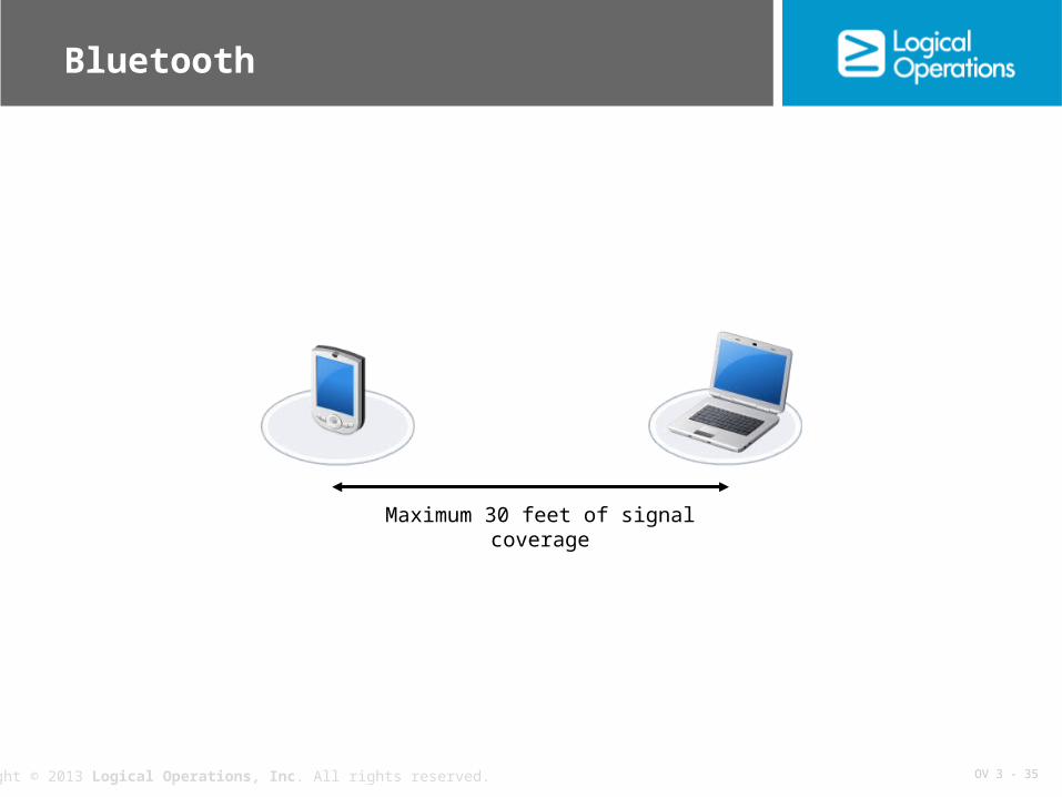
Bluetooth
Maximum 30 feet of signal coverage

OV 3 - 36Copyright © 2013 Logical Operations, Inc. All rights reserved.
Microwave Transmission
Sender transmits electromagnetic signals
Sender transmits electromagnetic signals
Receiver has an unobstructed viewReceiver has an
unobstructed view

OV 3 - 37Copyright © 2013 Logical Operations, Inc. All rights reserved.
Wireless Access Points
WAP
Device that provides a connection between wireless devices
Device that provides a connection between wireless devices

OV 3 - 38Copyright © 2013 Logical Operations, Inc. All rights reserved.
Electrical Noise
Noise in the network medium
Noise in the network medium

OV 3 - 39Copyright © 2013 Logical Operations, Inc. All rights reserved.
Sources of Electrical Noise
Noise Source Property
Ambient noise
Can come from many sources, including solar disturbances or radio broadcasting towers
Naturally occurring forms of noise Affect both bounded and unbounded media
Power wires
High-tension power lines can create electrical noise Network cables parallel to electric wires more susceptible to
electrical noise than those that run perpendicular
Electric motors
Used in elevators, refrigerators, water fountains, and HVAC equipment
Create noise while running Require huge amount of electricity to start up, causing noise Bursts create temporary outages
Electrical heat-generating devices
Use a lot of electricity Cause significant amount of electrical noise while running
Fluorescent, neon, and High-Intensity Discharge (HID) lights
Produce large amount of electrical noise Creates enough noise during operation to interfere with
networking signals

OV 3 - 40Copyright © 2013 Logical Operations, Inc. All rights reserved.
Grounding
Rack frame connects to the ground
Rack frame connects to the ground
Groundpoint
Groundpoint
ConductorConductor

OV 3 - 41Copyright © 2013 Logical Operations, Inc. All rights reserved.
Shielding
Drain
Noise
ShieldShield

OV 3 - 42Copyright © 2013 Logical Operations, Inc. All rights reserved.
Differential Signaling
Signal with positive noise
Signal with negative noise
Signal after removing the noise

OV 3 - 43Copyright © 2013 Logical Operations, Inc. All rights reserved.
Noise Control with Twisted Pair
Closely wound; less noise in the signalClosely wound; less noise in the signal
Loosely wound; more noise in the signalLoosely wound; more noise in the signal

OV 3 - 44Copyright © 2013 Logical Operations, Inc. All rights reserved.
Termination
Terminator Terminator
Prevents signal reflection
Prevents signal reflection

OV 3 - 45Copyright © 2013 Logical Operations, Inc. All rights reserved.
Noise Reduction Considerations
Noise Reduction Consideration
Description
Separate data and electrical cables
Do not run data and electricity cables in the same trays, raceways, and conduits
Avoid running network cables parallel to each other when you can
Fluorescent lights
Keep network cables at least 20 inches from fluorescent lights as it can cause electromagnetic interference
If you must run data cables across or near these lights, do so in such a way that exposes the smallest length of cable to the light
Power ground Make sure to ground all equipment and electrical circuits according
to the manufacturer's instructions and local building codes
Connector installation
Follow standards, specifications, and manufacturer's directions when installing network cables
Do not unwind conductor pairs any more than required or allowed Make sure connectors are firmly attached and connected to power
outlets

OV 3 - 46Copyright © 2013 Logical Operations, Inc. All rights reserved.
NICs
Network Interface Card (NIC): A device that serves as an interface between the computer and the network Also called as network adapter or network card Can be built into the motherboard of the computer or can be connected using a
USB, PC card, CompactFlash or FireWire port

OV 3 - 47Copyright © 2013 Logical Operations, Inc. All rights reserved.
Transceivers
Transceiver chipTransceiver chip
OV 3 - 48Copyright © 2013 Logical Operations, Inc. All rights reserved.
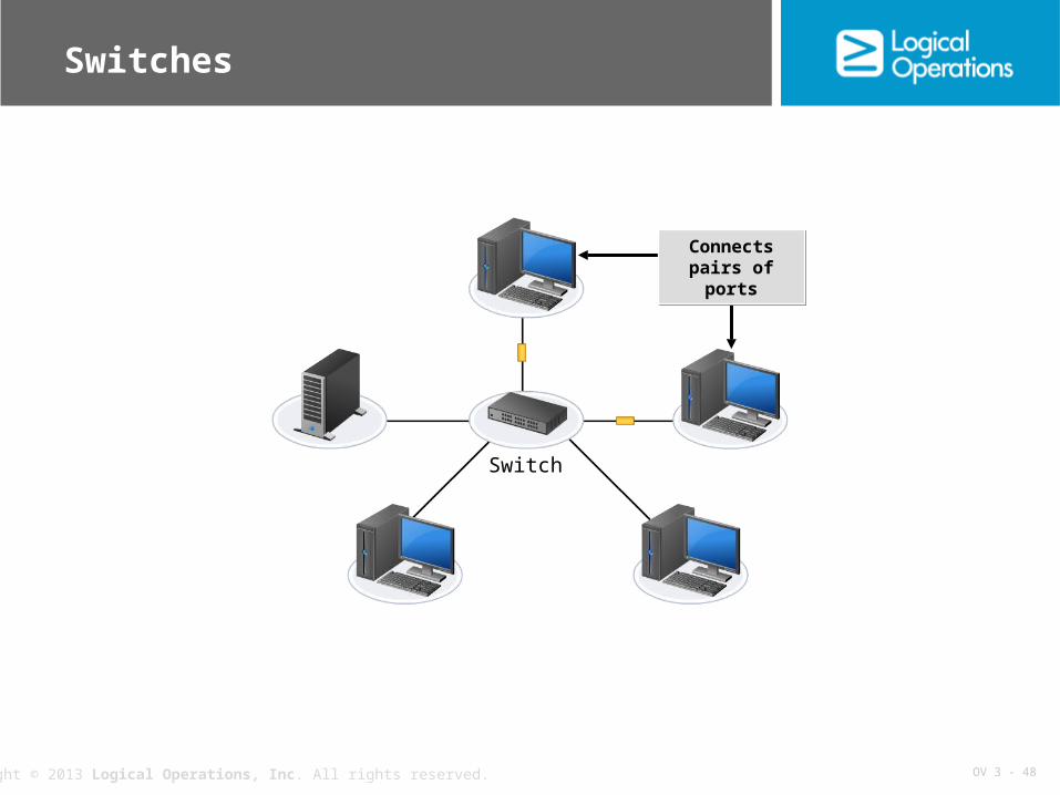
Switches
Switch
Connects pairs of ports
Connects pairs of ports
OV 3 - 49Copyright © 2013 Logical Operations, Inc. All rights reserved.
Virtual Switches
Software-based switch that provides functionality similar to physical switches Used to connect systems on a virtual network Contains a core forwarding unit that forwards packets to the correct virtual
systems Check MAC address of each packet like a physical switch, and forwards the
packet to one or more virtual ports for transmission Contains a VLAN tagging unit, a packet filtering unit, and a security unit Traffic cannot directly flow from one virtual switch to another in the same host
network Two virtual switches or VLANs cannot communicate directly

OV 3 - 50Copyright © 2013 Logical Operations, Inc. All rights reserved.
Routers
Router
Divides network based on network
addresses
Divides network based on network
addresses

OV 3 - 51Copyright © 2013 Logical Operations, Inc. All rights reserved.
Gateways
Gateway
LAN interface
LAN interface
WAN interface
WAN interface

OV 3 - 52Copyright © 2013 Logical Operations, Inc. All rights reserved.
Virtual Servers
Remote software that can run its own operating systems or applications Composed of only software components and behaves similar to a real
computer Has characteristics similar to a physical computer and contains its own virtual
software-based CPU, RAM, hard drive, and NIC Operating system will behave in the same manner as in physical servers No major functionality changes in the way applications or computer networks
behave Offer distinct advantages over physical servers

OV 3 - 53Copyright © 2013 Logical Operations, Inc. All rights reserved.
Virtual PBX
Private communications service provider that provides low cost PBX service Used to manage phone-based tasks such as voicemail, faxing, conference
calling, and call routing Physical PBX system – involves very high cost investment with expensive
hardware Virtual PBXs – allow smaller businesses to utilize PBX services without the
need for physical PBX Utilizes traditional Public Switched Telephone Network (PSTN) with Voice over
IP (VoIP) technology

OV 3 - 54Copyright © 2013 Logical Operations, Inc. All rights reserved.
NaaS
Organizations can purchase networking infrastructure, and when they do not need it, they can lease the network as a service to a client.
NaaS
PaaS IaaS

OV 3 - 55Copyright © 2013 Logical Operations, Inc. All rights reserved.
Legacy Network Connectivity Devices
Network Device
Description
Repeater
A device that regenerates a signal to improve signal strength over transmission distances
Using repeaters, you can exceed the normal limitations on segment lengths imposed by various networking technologies
Used frequently with coax media, such as cable TV Most networks today use twisted pair cabling Wireless network repeaters and bridges are frequently used to extend the range of a
WAP
Hub
A networking device to connect the nodes in a physical star topology network into a logical bus topology
Contains multiple ports to which the devices can be connected Two common types of hubs: passive and active Passive hub – receives data transmitted from a device to one port and broadcasts it
out to devices connected on all other ports Active hub – performs same receive then broadcast action as a passive hub, and
also regenerates or boosts the signal much like a repeater
Bridge
A network device that divides a logical bus network into segments Examine the MAC address of each packet Helps reduces traffic between segments and improves overall network performance

OV 3 - 56Copyright © 2013 Logical Operations, Inc. All rights reserved.
Reflective Questions
1. Which will you use more frequently in your networks: bounded or unbounded media?
2. Of the various networking devices, which offers you the best mix of features and functionality?