outdoor double full-height turnstile … · 1.1.1 name of product: outdoor double full-height...
TRANSCRIPT

laquoTiSO-PRODUCTIONraquo Company
OUTDOOR DOUBLE
FULL-HEIGHT TURNSTILE
Т12НYСХP
OPERATION MANUAL
AUIA443-0105 OM
2013
2 АUIА443000000-0105 OM
CONTENTS
Page
INTRODUCTIONhelliphelliphelliphelliphelliphelliphelliphelliphelliphelliphelliphelliphelliphelliphelliphelliphelliphelliphelliphelliphelliphelliphellip 3
1 DESCRIPTION AND OPERATIONhelliphelliphelliphelliphelliphelliphelliphelliphelliphelliphelliphelliphelliphelliphellip 5
11 General Information and Designationhelliphelliphelliphelliphelliphelliphelliphelliphelliphelliphelliphellip 5
12 Specificationshelliphelliphelliphelliphelliphelliphelliphelliphelliphelliphelliphelliphelliphelliphelliphelliphelliphelliphelliphelliphelliphellip 6
13 Configuration and Completeness of Deliveryhelliphelliphelliphelliphelliphelliphelliphelliphelliphellip 6
14 Design and Operationhelliphelliphelliphelliphelliphelliphelliphelliphelliphelliphelliphelliphelliphelliphelliphelliphelliphelliphelliphelliphellip 7
15 Instrumentation tools and accessorieshelliphelliphelliphelliphelliphelliphelliphelliphelliphelliphelliphelliphelliphellip 10
16 Markinghelliphelliphelliphelliphelliphelliphelliphelliphelliphelliphelliphelliphelliphelliphelliphelliphelliphelliphelliphelliphelliphelliphellip 10
17 Packinghelliphelliphelliphelliphelliphelliphelliphelliphelliphelliphelliphelliphelliphelliphelliphelliphelliphelliphelliphelliphelliphelliphelliphelliphellip 11
18 Description and operation of controller as component of the turnstile 11
2 INTENDED USEhelliphelliphelliphelliphelliphelliphelliphelliphelliphelliphelliphelliphelliphellip 20
21 Operating limitationshelliphelliphelliphelliphelliphelliphelliphelliphelliphelliphelliphelliphelliphelliphelliphelliphelliphelliphellip 20
22 Layout and installationhelliphelliphelliphelliphelliphelliphelliphelliphelliphelliphelliphelliphelliphelliphelliphelliphelliphellip 20
23 Preparation for usehelliphelliphelliphelliphellip 21
24 Contingency actionshelliphelliphelliphelliphelliphelliphelliphelliphelliphelliphelliphelliphelliphelliphelliphelliphelliphelliphelliphellip 22
3 MAINTENANCEhelliphelliphelliphelliphelliphelliphelliphelliphelliphelliphelliphelliphelliphelliphelliphelliphelliphelliphelliphelliphelliphelliphellip 22
31 General instructionshelliphelliphelliphelliphelliphelliphelliphelliphelliphelliphelliphelliphelliphellip 22
32 Safety measureshelliphelliphelliphelliphelliphelliphelliphelliphelliphelliphelliphelliphelliphellip 22
33 Maintenance procedurehelliphelliphelliphelliphelliphelliphelliphelliphellip 23
4 ROUTINE MAINTENANCEhelliphelliphelliphelliphelliphelliphelliphelliphelliphelliphelliphelliphelliphelliphelliphelliphelliphelliphellip 23
41 General instructionshelliphelliphelliphelliphelliphelliphelliphelliphelliphellip 23
42 Fault Directoryhelliphelliphelliphelliphelliphelliphelliphelliphellip 23
43 Post repair checkouthelliphelliphelliphelliphelliphelliphelliphelliphelliphelliphelliphellip 24
5 TRANSPORTATION AND STORAGE helliphelliphelliphelliphelliphelliphelliphelliphelliphelliphelliphelliphelliphellip 24
6 UTILIZATIONhelliphelliphelliphelliphelliphelliphelliphelliphelliphelliphelliphelliphelliphelliphelliphelliphelliphelliphelliphelliphelliphelliphelliphelliphellip 25
7 MANUFACTURERrsquoS WARRANTY AND CONDITIONS OF INTERMEDIATE
MAINTENANCEhelliphelliphelliphelliphelliphelliphelliphelliphelliphelliphelliphelliphelliphelliphelliphelliphelliphelliphelliphellip
25
Appendix А Design overall and installation dimensions of the Outdoor Double Full-
Height Turnstile T12НYCXP helliphelliphelliphelliphelliphelliphelliphelliphelliphellip
26
Appendix B Control panel and connection diagramhelliphelliphelliphelliphelliphellip 27
Appendix C Wiring diagram of the turnstile T12НYCXP helliphelliphelliphellip 29
3 АUIА443000000-0105 OM
INTRODUCTION
This Operation Manual (hereinafter referred to as the OM) combined with certificate covers the
Outdoor Double Full-Height Turnstile (hereinafter referred to as the turnstile) The Operation Manual
contains information about design specifications installation proper operation and maintenance of
the turnstile
This Operation Manual is prepared in compliance with the specification requirements ТU
U 316-316-32421280-0032010
The turnstile should be serviced only by the qualified staff having the relevant class of permit to work
with electrical facilities with voltage up to 1000V who carefully studied this Operation Manual
obtained safety instructions and trained for operation and maintenance of the turnstile
Reliability and durability of the turnstile operation is provided with observation of modes and
conditions of transportation storage installation and operation So fulfillment of all requirements
specified in this document is mandatory
In view of regularly performed works on improvement of the product its design can be modified
without degradation of parameters and quality of the product
Depending on the purpose and design features of the turnstile the following pattern of product
reference designation is accepted
Т1 2 НYС
X P
Full-Height Turnstile Straight barrier rods
Double
К Painted housing
Outdoor Н Н Stainless steel
barrier rods at the angle 120deg Y Z Galvanized housing
with servomotor С
Example of reference designation of the Double Full-Height Turnstile with servomotor straight
barrier rods and painted housing when the turnstile
T12HYCKР ТU U 316-32421280-0032010 is ordered
4 АUIА443000000-0105 OM
WARNINGS TO THE CUSTOMER
ON SAFE OPERATION OF THE TURNSTILE
These warnings are designed for ensuring of safety during operation of the turnstile to prevent
violation of safety characteristics by improper installation or operation These warnings are aimed at
drawing attention of the customer to safety problems
GENERAL WARNINGS
Safety measures and requirements specified in this in this OM must be observed
ndash the turnstile must be connected to ground loop prior to operation
ndash the turnstile should be connected to AC network with parameters specified in the paragraph 12
laquoSpecificationsraquo
ndash inspection adjustment and repair should be performed only after the turnstile is deenergized
After purchasing of the turnstile it should be unpacked and its integrity should be checked In case of
doubt in integrity of the turnstile it should not be used and the customer should refer to the supplier or
to the manufacturer
Packing accessories (wooden pallet nails clips polyethylene bags cardboard etc) as potential
sources of hazard must be removed to unacceptable place prior to proper use of the turnstile
As electric shock protection device the turnstile is related to 01 protection class according to the
GOST (State Standard) 1220070-75 and is not intended for operation in explosive and fire-
hazardous areas by the laquoRules for design of electrical installationsraquo
Using of the turnstile for unintended purpose improper installation nonobservance of conditions of
transportation storage installation and operation specified by this OM may result in damage to
people animals or property for which the manufacturer is not responsible
5 АUIА443000000-0105 OM
1 DESCRIPTION AND OPERATION
11 General Information and Designation
111 Name of product Outdoor Double Full-Height Turnstile
Climatic version N1
112 The turnstile is designed for pedestrian movement control at access points of industrial
enterprises banks stadiums administrative facilities etc under actuation of control signals (coming
from magnetic card readers keypad etc) of access control system or manually (from control panel)
Traffic flow capacity of the turnstile without personal identification is at least 40 persons per minute
113 Dimensions and weight of the turnstile correspond to the values are specified in the Table 1
Table 1
Designation of modification Dimensions mm
Max weight kg Н L В
T12HYCKP
2350 1207 2240 560 T12HYCHP
T12HYCZP
114 The parameters defining operation conditions according to GOST 15150-69 and GOST
12997-84 are specified in the Table 2 Table 2
Operation conditions For climatic
version Parameter value
Ambient temperature
N1
- 40degС to + 45degС
Relative humidity 80 at + 25ordmС
Ambient temperature allowable
pressure 84 to 1067kPa
Transportation temperature range - 50degС to + 50degС
Storage temperature range + 5 to + 40degС
Group of mechanical application L3
Altitude above sea level up to 2000m
Environment NF4
Explosion-proof does not contain
current-conducting dust aggressive gases
and vapours in concentration destroying
isolation and metals disturbing normal
operation of the equipment installed in
turnstiles
Installation site
N1
In unheated spaces and outdoor
Running position Vertical deviation from vertical position
no more than 1ordm to any side is tolerated
115 Reliability indices
ndash mean time to repair (without delivery time of spare parts tools and accessories) ndash at most 6
hours
ndash mean time to failure ndash at least 1 500 000 accesses
ndash mean service life between overhauls ndash at least 10 years
12 Specifications
Principal parameters of the turnstile are specified in the Table 3
6 АUIА443000000-0105 OM
Table 3
Parameter description Unit measure Parameter value
Traffic flow capacity in free access mode is at least manmin 40
Max passage width mm 649
Supply voltage
ndash AC power supply (primary) V
Hz 100 240
~ 5060
ndash DC power supply (secondary) В 12
Max power consumption VА 800
Index of protection according to GOST 14254-96 ndash IP54
13 Configuration and Completeness of Delivery
131 Turnstile design
1311 Design of the Double Full-Height Turnstile includes the following principal devices and
components (see the Figure 1)
ndash prefabricated arched structure including
1) two passage walls
2) middle wall
3) frame
4) canopies
ndash two rotors
ndash two container with control mechanisms
ndash LED displays
ndash heating system of control mechanism and electronic components
ndash control panels
ndash electrical equipment
1312 The turnstile modification with straight barrier rods (reference designation T12HYCХP)
1313 The turnstile modifications are manufactured from the following materials
ndash carbon steel subject to painting (reference designation T12HYCКР )
ndash polished or brushed stainless steel (reference designation T12HYCHР)
ndash carbon steel subject to galvanization (reference designation T12HYCZР)
The turnstilersquos basic modification is with straight barrier rods and painted steel housing (reference
designation T12HYCКР)
Modification overall and installation dimensions of the turnstile are shown in the Appendix A
132 Completeness of Delivery
The turnstile is supplied ready-to-install or by components
Completeness of delivery is specified in the Table 4
Table 4
Name of product Product
designationparameters
Quantity
piece Notes
Outdoor Double Full-
Height Turnstile T12HYC_______ 1 kit ndash
Components
Control panel AUIA114020000 2 ndash
Canopies 1 kit ndash
7 АUIА443000000-0105 OM
Frame 1 ndash
Frame installation kit
Screw М12 х 40019
GOST 11738-84 18
To be delivered along with
frame Washer 1265G019
GOST 6402-70 18
Plastic plug 8 When kit of canopies is absent
Battery 12V
17Аmiddoth 2 Backup Power Supply
Turnstile installation kit
(without frame)
Redibolt 92F112A2-0
(12times120 М10) 18 ndash
Certificate AUIA443-0105 PS 1 ndash
Packing ndash 1 ndash
Optional
When the turnstile is ordered ready-to-install it is delivered by three packages
1) packing of two rotors (without container) dimensions of which are (НхLхW)
1075х2156х1286mm
2) packing of two containers dimensions of which are (НхLхW) 625х1308х926mm
3) packing of frame and walls dimensions of which are (НхLхW) 830х2226х1366mm
14 Design and operation
141 Turnstile design
1411 Prefabricated arched structure (see the Figure 1) consists of two passage walls 1 middle wall 8
and two rotors 7 The top connecting bar of the structure is two containers 5 inside which the turnstile
control mechanism and electrical equipment (power supply and control units batteries controllers
heating systems etc) are located At the top the arched structure is equipped with canopies 2 which
are fixed to walls with self-tapping screws
1412 Both revolving rotors 7 divided into three sectors each of 120ordm is located between passage
wall 1 and middle wall 8 Upper parts of rotors are linked with shafts of control mechanisms through
halfcouplings Supports of revolving rotors and walls are fixed to frame 4 or floor by means of
Redibolt
A special space (airlock) is provided in the turnstile design that enables to use tight access control on
site 1413 Designs of control mechanisms (see the Figure 2) are similar and consist of bottom and upper
plates (1 and 2) on which primary components of structure are located
On the shaft between the plates ratchet gears (3 and 4) are located which are locked with latches (5
and 6) In interlocking position with ratchet gears the latches are pushed by springs (7 and 8) Ratchet
gears are disconnected by means of solenoids (9 and 10) which at actuation provide rotation of the
relevant latches and unlocking of the relevant ratchet gear
Rotor is driven to initial position (when ratchet gear with its tooth abuts against latch) by servomotor
Control sensors of rotor initial position and direction of its rotation is optocouple (18 19) operating in
consolidation with sprocket disk (16 17) rigidly connected to the shaft of ratchet gears
Locks (23 and 24) are designed for manual unlocking of the turnstile
Position of mechanical unlocking locks is controlled by microswitches (25 and 26)
Solenoids (9 and 10) operate in laquoboostraquo mode (ie supply of additional voltage up to the level of 24V-
27V) provided by microswitches (27 and 28) depending on position of latches
8 АUIА443000000-0105 OM
1 ndash passage wall
5 ndash container
2 ndash canopies 6 ndash straight barrier rod
3 ndash LED display 7 ndash rotor
4 ndash frame 8 ndash middle wall
Figure 1 ndash Full-Height Turnstile with straight barrier rods
1414 Electrical equipment of the turnstile installed and located inside container is designed for
operation control of actuating mechanisms and LED display of the turnstile both as part of access
control system and by means of control panel
Electrical equipment of the turnstile includes heating systems of control mechanism and electronic
components located in container (thermal element resistors and thermostat card) as well as controller
power supply battery wired and distribution electrical accessories
Connection of the turnstile heating system is provided by switch S2 according to the wiring diagram
shown in the Appendix C
1415 LED displays are located on posts of the turnstile at the entrance and they are designed for
visual display of information about definition and execution of instructions coming from control
system (control panel ACS or keypad) to actuating mechanisms of the turnstile
1416 Control panel is made as small desktop device in plastic case designed for setting and
indication of operation modes when the turnstile is operated manually Control panel and its
connection diagram are shown in the Appendix B
1417 In order to ensure operation of the turnstile as part of access control system (ACS) the
following components are used as elements of this system
ndash Complex of ACS technical means
ndash ACS software
ndash Card badge etc readers
ndash Cards badges etc
9 АUIА443000000-0105 OM
ndash Airlocking keypad
ndash Technical means of permit issuance
The Manufacturer delivers the listed above as agreed by the parties under separate contract
31
1 ndash bottom plate 12 ndash drive pinion
2 ndash upper plate 13 ndash gear motor
3 4 ndash ratchet gears 16 17 ndash sprocket disk
5 6 ndash latches 18 19 ndash sensor card
7 8 ndash springs 23 24 ndash locks
9 10 ndash solenoids 25 26 27 28 ndash microswitches
11 ndash driven pinion 29 30 ndash converters
31 ndash half-coupling
Figure 2 ndash Control mechanism
10 АUIА443000000-0105 OM
142 Principle of operation
1421 For setting and indication of operating modes under manual control of each turnstile access a
particular control panel with similar principle of operation is used In the initial state (when solenoids of control mechanism are deenergized) rotor is locked from
rotation in both directions
1422 When access enabling command is given to controller in one of directions
ndash Green arrow is lit on LED display
ndash The relevant solenoid is energized
ndash The turnstile is unlocked in the relevant direction and the turnstile accessor is able to revolve
rotor manually to 120
1423 As soon as rotor starts revolving the red symbol laquo rsaquolsaquo raquo is lit on the LED display
1424 When rotor reaches the angle 60 its reverse movement is automatically locked This position
of rotor can be used for arrangement of airlock
In the airlock mode rotor turns to the angle 60ordm and it is automatically locked from rotation The
accessor is in airlock After code is dialed on keypad installed on post of passage wall and obtaining
access enabling command by control mechanism another rotation of rotor to 60ordm is possible to exit the
airlock
More detailed description of the turnstile operation modes is given in the paragraph 18 laquoDescription
and operation of controller as component of the turnstileraquo
1425 12V DC power voltage is provided by power supply unit
1426 When mains power supply is off the turnstile is automatically switched to the power supply
from 12V 17Amiddoth battery (optional) which ensures the turnstiles operation within at least 2 hours
1427 The turnstilersquos wiring diagram is shown in the Appendix C
15 Instrumentation tools and accessories
Dedicated tools are required for installation of the turnstile (multi-purpose measurement
instrumentation and installation tools are enough)
16 Marking
161 Marking of turnstiles to be delivered within Ukraine is in Ukrainian language and for export
delivery in English Each turnstile is marked as follows ndash name of manufacturer and trade mark
ndash reference designation of turnstile modification
ndash index of protection
ndash serial number
ndash value of voltage type of current frequency and current consumption
ndash weight kg
ndash marks of conformity to
ndash date of manufacture
ndash inscription laquoMADE IN UKRAINEraquo
Marking plate is located on container of the turnstile
162 Marking of transportation packing contains as follows
1) Information inscriptions
ndash reference designation of the turnstile modification
ndash dimensions of cargo package in centimeters
ndash gross and net weight in kg
11 АUIА443000000-0105 OM
ndash volume of package in cubic meters
ndash contract number
ndash name of consignee
ndash name of exporter
ndash full address of consignor
2) Handling marks
ndash laquoFragile Handle with Careraquo
ndash laquoKeep dryraquo
ndash laquoCentre of gravityraquo
ndash laquoTopraquo
163 Shipping documentation is packed with bag from polyethylene film Marking is applied on insert
from cardboard or paper
17 Packing
171 The turnstile is delivered ready-to-install
Types of packing
ndash consumer packaging (corrugated cardboard case)
ndash transportation packaging (cases from wood-fiber board or crates)
The turnstile is fixed from displacement in the middle of transportation package with LOCKING
lumbers Cushion pads are placed between the turnstile and lumbers
172 Shipping documentation sealed in a bag from polyethylene film is enclosed to the package No1
18 DESCRIPTION AND OPERATION OF CONTROLLER AS COMPONENT OF THE
TURNSTILE
181 The turnstile controller РСВ112212000
1811 The controller is performed on the (104х68)mm card Field-effect transistors are used to
control solenoids and indicators
19 light emitting diodes are installed on the controller card Their purpose is as follows
5 light emitting diodes display state of the external connection inputs laquoINP1raquo divide laquoINP5raquo
the light emitting diode laquoPOWERraquo displays existence of 5V power supply voltage
the light emitting diode laquoOPERATEraquo displays operating capacity of microprocessor
7 light emitting diodes display state of the external connection outputs laquoOUT1raquo divide laquoOUT7raquo
3 light emitting diodes laquoSENSORraquo display state of rotor position sensor
the light emitting diodes laquoRXraquo and laquoTXraquo display transceiving on serial port
40 terminal clips for connection of wires are installed on the card 14 of which are designed for
external connections and the rest are designed for connection to the turnstile units or are standby
1812 Technical features
The controller technical features are specified in the Table 5
Table 5
Parameter description Parameter value
Number of inputs for reception of control commands 5
Number of signal outputs 7
Type of inputs logical
Type of outputs open collector
Voltage of logical laquo1raquo (3 5)V
Voltage of logical laquo0raquo (0 22)V
Maximum peak voltage supplied to the inputs laquoINP1raquo divide laquoINP5raquo 15V
Peak voltage switched by transistors of signal output transistors 50V
12 АUIА443000000-0105 OM
Peak current switched through signal outputs 01А
Power supply voltage of controller (9 15)V
Peak consumption current 015А
Number of signal transceiving serial ports (RS-485) 1
Climatic version and category of location
according to the GOST 15150-69 NF4
Appearance of the controller is shown in the Figure 3
Figure 3 ndash Appearance of the controller РСВ112212000
1813 Description of operation
Controller operates according to the program entered into memory of microprocessor Mechanism and
LED display of the turnstile are controlled depending on control commands and rotor position sensors
based on the logic entered into program Control commands can be transmitted via RS-485 (from
control panel) or logical inputs by means of closing and opening laquoINP1raquo divide laquoINP5raquo on laquoGNDraquo
Controller (and therefore the turnstile) can be in laquoINITIAL STATEraquo (closed for access) or in one of
the following access modes
13 АUIА443000000-0105 OM
laquoSINGLE ACCESS IN ONE DIRECTION WITHOUT AIRLOCKraquo
laquoSINGLE ACCESS IN ONE DIRECTION WITH AIRLOCK FUNCTIONraquo
laquoFREE ACCESS IN ONE DIRECTIONraquo
laquoMECHANICAL UNLOCKING IN ONE DIRECTIONraquo
Other operating modes are combinations of various or identical basic modes in different directions
Single access in one direction without airlock and any of basic modes in opposite direction
Single access in one direction with airlock function and any of basic modes in opposite direction
Free access in one direction and any of basic modes in opposite direction
Mechanical unlocking in one direction and any of the above modes in opposite direction
18131 laquoINITIAL STATEraquo
Controller is in this mode if the commands laquoOPEN АВraquo are absent and the turnstile rotor is set to the
point 0ordm 120ordm or 240ordm
In this mode solenoids are deenergized and rotor is locked
Red inhibit LED display is lit in both directions
18132 laquoSINGLE ACCESS IN ONE DIRECTION WITHOUT AIRLOCKraquo
In this mode controller unlocks rotor via solenoid in one direction with possibility of its rotation to
120ordm It enables turnstile access of one pedestrian without a stop in the point 60ordm (airlock)
Controller goes to laquoSINGLE ACCESS IN ONE DIRECTIONraquo if in laquoINITIAL STATEraquo it receives
the command laquoOPEN АВraquo (active level of signal is given to the input laquoINP4raquo or laquoINP5raquo Turnstile
is open during action of signal) Command can also come through RS-485
In this case if command is received through the input laquoINP4raquo or laquoINP5raquo controller waits for
laquoSTARTraquo of rotor rotation during active status of signal on the relevant input laquoINP4raquo or laquoINP5raquo and
if controller has received the command laquoOPEN АВraquo though RS-485 then laquoSTARTraquo of rotor rotation
is expected before ending of delay laquoWAITING FOR START OF ACCESSraquo
Sequence of actions of controller after reception of the command laquoOPEN АВraquo is as follows
Delay of laquoWAITING FOR START OF ACCESSraquo is initiated
Controller energizes solenoid and thus unlocks rotor in the relevant direction
LED display corresponding to authorized access is switched from red to green
If during delay of laquoWAITING FOR START OF ACCESSraquo rotor rotation has started then further
behaviour of controller depends on the angle of rotor rotation
6ordm of rotor rotation ndash LED display is switched from red to green indicating occupation
of access The output signal laquoSTART OF ACCESS АВraquo (laquoOUT1raquo or laquoOUT2raquo)
assumes active status Delay of laquoWAITING FOR START OF ACCESSraquo is cancelled
10ordm of rotor rotation ndash status of the relevant input laquoAIRLOCK ABraquo is verified If
command is active controller goes to the mode laquoSINGLE ACCESS IN ONE DIRECTION
WITH AIRLOCK FUNCTIONraquo If by this moment the command laquoAIRLOCKraquo of the
relevant direction has not come then controller further operates in the mode laquoSINGLE
ACCESS IN ONE DIRECTION WITHOUT AIRLOCKraquo
58ordm of rotor rotation ndash the signal laquoSTART OF ACCESS ABraquo (laquoOUT1raquo or laquoOUT2raquo) is
cancelled and the signal laquoAIRLOCK POINT ABraquo (laquoOUT5raquo) appears
60ordm of rotor rotation ndash when this point is entered rotor canrsquot be returned to the point 0ordm
(in opposite direction) without the command laquoRETURNraquo (laquoINP1raquo) being given or actuation
of the laquoFREE ACCESSraquo mode via RS-485 in opposite direction
64ordm of rotor rotation ndash the signal laquoDETECTION OF ACCESS АВraquo (laquoOUT3raquo or
laquoOUT4raquo) is generated
70ordm of rotor rotation ndash the relevant solenoid is deenergized preparing rotor for locking
in the point 120ordm (0ordm for next access)
120ordm of rotor rotation ndash the signals laquoAIRLOCK POINT ABraquo (laquoOUT5raquo) and the
relevant signal laquoDETECTION OF ACCESS АВraquo (laquoOUT3raquo or laquoOUT4raquo) are cancelled and
after that availability of the command laquoOPEN ABraquo (laquoOUT3raquo or laquoOUT4raquo) corresponding to
14 АUIА443000000-0105 OM
the current direction of access is verified and if command by that moment is active then
controller goes to the laquoFREE ACCESSraquo mode
18133 laquoSINGLE ACCESS IN ONE DIRECTION WITH AIRLOCK FUNCTIONraquo
In this mode controller unlocks rotor via solenoid in one direction with possibility of its rotation to
60ordm After that rotor can be unlocked in any direction that enables to arrange the second level of
identification and authorize completion of access or exit in opposite direction according to
identification results
Controller goes to the mode laquoSINGLE ACCESS WITH AIRLOCK FUNCTIONraquo if in laquoINITIAL
STATEraquo the command laquoAIRLOCK ABraquo (laquoINP2raquo or laquoINP3raquo) is active In this case controller
received the relevant command laquoOPEN ABraquo goes to the mode laquoSINGLE ACCESS IN ONE
DIRECTION WITH AIRLOCK FUNCTIONraquo
Controller also goes to the mode laquoSINGLE ACCESS WITH AIRLOCK FUNCTIONraquo if the turnstile
has started to operate in one of directions in the laquoSINGLE ACCESSraquo mode and when rotor reaches
10ordm angle the command laquoAIRLOCKraquo is activated in the direction of current access and later on access
will be with airlock function
Difference of controller operation in this mode from the mode laquoSINGLE ACCESS IN ONE
DIRECTION WITHOUT AIRLOCKraquo is as follows
When rotor reaches the position 10ordm controller deenergizes the solenoid of current access and the
solenoid of opposite direction if in opposite direction laquoFREE ACCESSraquo is turned on
Rotor gets to 60ordm with two deenergized solenoids that results in its locking
After that rotor can be unlocked again in straight direction (the direction of continued access) by
cancellation of the relevant command laquoAIRLOCKraquo (laquoINP2raquo laquoINP3raquo) or by giving via RS-485
the command laquoFREE ACCESSraquo in the current direction The difference is that having received
via RS-485 the command laquoFREE ACCESSraquo rotor will not be locked in the current direction in
the point 120ordm
From the position laquoAIRELOCKraquo rotor canrsquot be unlocked for exit in opposite direction by giving
the command laquoRETURNraquo (active level of signal on the input laquoINP1raquo) or by giving via RS-485
the command laquoFREE ACCESSraquo in opposite direction The difference is that having received via
RS-485 the command laquoFREE ACCESSraquo via RS-485 rotor will not be locked in the point 0ordm
18134 laquoFREE ACCESS IN ONE DIRECTIONraquo
In this mode rotor can rotate freely in the free access direction In opposite direction rotor can rotate
only up to the nearest locking point ie to 60ordm In the laquoFREE ACCESSraquo mode LED display of thy
relevant direction is blinking green
Controller is switched to this mode in two cases
First ndash when the command laquoOPEN АВraquo (input laquoINP4raquo or laquoINP5raquo) is kept in active status in the
moment of crossing by rotor of the point 120ordm when laquoSINGLE ACCESSraquo is finished
Second ndash immediately after reception of the command laquoFREE ACCESSraquo via RS-485 in the
relevant direction
After controller is switched to the laquoFREE ACCESSraquo mode the status of the command laquoAIRLOCKraquo
of the relevant direction is of no importance and output signals laquoSTART OF ACCESSraquo
laquoDETECTION OF ACCESSraquo and laquoAIRLOCK POINTraquo of the appropriate direction are not
generated
Quitting from this mode into laquoINITIAL STATEraquo is performed after cancellation of the command
laquoOPEN ABraquo or reception of the command laquoCANCELLATION OF FREE ACCESSraquo via RS-485
But it occurs not immediately and only when rotor reaches one of the start points 0ordm 120ordm or 240ordm ie
if free access is cancelled during started access then it will be finished as free access
18135 laquoMECHANICAL UNLOCKINGraquo
15 АUIА443000000-0105 OM
In this mode rotor can rotate freely in the direction of mechanically unlocked access It is done in
order to enable the turnstile access in case of emergency as well as when standby battery is completely
discharged or malfunction of electronic equipment
The turnstile is switched to this mode by turning of mechanical key Having received signal from the
microswitch related to mechanical key controller goes to the mode laquoMECHANICAL UNLOCKINGraquo
in the appropriate direction Since in this mode controller is unable to have effect on passage
operation so LED display is identical to free access that is green LED display of unlocked access is
blinking and red LED display is OFF No output signals related to mechanically unlocked access are
generated
Quitting from this mode is performed after turning of the key laquoMECHANICAL UNLOCKINGraquo to
initial state
18136 laquoPERMISSION OF SINGLE ACCESS IN BOTH DIRECTIONSraquo
Since the turnstile is unable to rotate in both directions at a time so controller can only unlock rotor in
both directions and when access is started in one of directions the opposite direction will be closed
Controller goes to this mode if it simultaneously receives the commands laquoOPEN Araquo and laquoOPEN
Braquo in laquoINITIAL STATEraquo The second signal can also come when the first signal is already active but
rotor has not started to rotate
In this case
Controller unlocks rotor in both directions via solenoids
Both LED displays are switched from red to green
Two delays of laquoWAITING FOR START OF ACCESS Araquo are actuated for each access
particularly which are counted from the moment of coming of commands
Controller is waiting for starting of access
After rotor is turned to 6ordm in any side the solenoid of opposite direction will be OFF LED display
will be switched to red and delay of laquoWAITING FOR START OF ACCESSraquo of opposite
direction will be cancelled
Then controller is operating as it is described in the paragraph laquoSINGLE ACCESS IN ONE
DIRECTIONraquo
If during active status of the signals laquoOPEN Araquo and laquoOPEN Braquo rotor is not turned to any side to
the angle gt 6ordm then controller goes to laquoINITIAL STATEraquo
Purpose of the controller contacts designed for connection of peripherals is specified in the Table 6
Table 6
Connectorcontact No
Description Direction Designation Signal description and
parameters
ХТ11 INP1
(laquoRETURNraquo) ENTRY
Command laquoOpen from
locked position in airlock in
opposite directionraquo
1) logical laquo0raquo
(0 22)V
2) logical laquo1raquo
(3 5)V
3) active level of
signal (factory
setting) ndash logical
laquo0raquo
4) voltage on open
input lt 5V
ХТ12 INP2
(laquoAIRLOCK Araquo) ENTRY
Command laquoLock rotor at
60deg raquo Command should be
cancelled to unlock rotor in
straight direction If signal is
available during entry after
rotor reaches 15deg then rotor
will be locked at 60deg
otherwise rotor will be locked
only at 120deg
ХТ13 INP3
(laquoAIRLOCK Вraquo) ENTRY
ХТ14 INP4
(laquoOPEN Araquo) ENTRY
Command laquoOPEN FOR
SINGLEFREE ACCESSraquo
free access appears when
1) logical laquo0raquo
(0 22)V
2) logical laquo1raquo ХТ15 INP5 ENTRY
16 АUIА443000000-0105 OM
(laquoOPEN Braquo) entry is kept in active status
after timeout waiting for start
of access (~ 5 s) is expired or
from the moment when rotor
reaches the angle 96deg
(3 5)V
3) active level of
signal (factory
setting) ndash logical
laquo0raquo
4) voltage on open
input lt 5V
ХТ16 GND (common)
ХТ27 GND (common)
ХТ28
OUT1
(laquoSTART OF
ACCESS Araquo)
EXIT Signal is generated by
controller when the command
laquoOPENraquo is received and rotor
rotation in the same direction
is detected
1) type of output ndash
open collector
2) peak voltage on
privacy key 55V
3) peak current of
public key 100mA
4) resistance of
public key
(5 7)Ohm
ХТ29
OUT2
(laquoSTART OF
ACCESS Braquo)
EXIT
ХТ210
OUT3
(laquoDETECTION
OF ACCESS Araquo)
EXIT Signal is generated by
controller when rotor is
rotating from 64ordm ХТ211
OUT4
(laquoDETECTION
OF ACCESS Braquo)
EXIT
ХТ212
OUT5
(laquoAIRLOCK
POINTraquo)
EXIT
Signal is generated by
controller when rotor reaches
the angle 54ordm
ХТ213 OUT6
(laquoERRORraquo) EXIT
Signal is generated by
controller when fault of
behaviour is detected 5) active level of
signal (factory
setting) ndash logical laquo0raquo ХТ214
OUT7
(laquoPASSAGE IS
OCCUPIEDraquo)
EXIT
Signal is generated by
controller starting from the
angle 2ordm to 118ordm
ХТ315 OPTO1 ENTRY Used for obtaining of
information about turnstile
rotor position
1) logical laquo0raquo
(0 22)V
2) logical laquo1raquo ndash
(3 5)V
3) active level of
signal (factory
setting) ndash logical
laquo0raquo
4) voltage on open
input lt 5V
ХТ316 OPTO2 ENTRY
ХТ317 OPTO3 ENTRY
ХТ318 SGN1 ENTRY
Used for obtaining of
information about mechanical
unlocking of turnstile rotor ХТ319 SGN2 ENTRY
ХТ320 SGN3 ENTRY Not applicable
ХТ321 SGN4 ENTRY
ХТ322 INDAR EXIT
Used for control of LED
displays
1) type of output ndash
open collector
2) peak voltage on
privacy key 30V
3) peak current of
public key 2A
ХТ323 INDAG EXIT
17 АUIА443000000-0105 OM
ХТ324 INDBR EXIT
4) resistance of
public key 01Ohm
ХТ325 INDBG EXIT
ХТ326 PSW1 EXIT
Used for energizing of
external units
1) type of output ndash
open emitter
2) voltage on output
in ON state 12V
3) peak current
consumed from the
output 1A
4) resistance of
public key 025Ohm
ХТ327 PSW2 EXIT
ХТ328 RSВ Used for data transmission
via serial port
Interface RS-485
ХТ329 RSА Interface RS-485
ХТ330 SH RS-485 SCREEN
ХТ431 - MGA EXIT Used for control of solenoids
of rotor mechanism
1) type of output ndash
open collector
2) peak voltage on
privacy key 50V
3) peak current of
public key 9A
4) resistance of
public key 011Ohm ХТ433 - MGB EXIT
ХТ432 + MGA Connection of cathodes of
protective diodes to positive
output of solenoids power
supply
ХТ434 + MGB
ХТ535 + 12V 1) voltage 12V
2) consumption
current lt 150mA ХТ536 + 12V
ХТ537 + 12V
ХТ538 GND (common)
ХТ539 GND (common)
ХТ540 GND (common)
182 Controller РСВ201010000
1821 The Controller PCB201010000 is designed for motor control of motorized turnstile
The Controller is assembled on the (85х70)mm card on which electronic components and connectors
for external connections are installed
On controller card 13 LEDs are installed Their purpose is as follows
8 LEDs indicate condition of inputs laquoIN1raquo laquoIN8raquo
laquoPOWERraquo LED indicates availability of supply voltage 5V
4 LEDs indicate condition of outputs for connection of motor
24 terminals are installed on the card 2 of them are designed for external connections the rest are
designed for connection to turnstile units or are standby
1822 Technical features
The controller technical features are specified in the Table 7 Table 7
Parameter description Parameter value
Number of inputs for reception of control commands 2
18 АUIА443000000-0105 OM
X31
X35
70 mm
60 mm
75
mm
85
mm
Oslash4 mm
Number of signal outputs 4
Type of inputs logical
Type of outputs laquoGRN1raquo laquoRED1raquo laquoGRN2raquo laquoRED2raquo open collector
Logical laquo1raquo voltage (37 5)V
Logical laquo0raquo voltage (0 17)V
Peak voltage applied to inputs laquoIN1raquodividelaquo IN8raquo maximum 15V
Peak voltage switched by outputs laquoGRN1raquo laquoRED1raquo laquoGRN2raquo laquoRED2raquo 30V
Peak current switched by outputs laquoGRN1raquo laquoRED1raquo laquoGRN2raquo laquoRED2raquo 2А
Peak voltage switched by outputs laquo-MG1raquo laquo-MG2raquo 50V
Peak current switched by outputs laquo-MG1raquo laquo-MG2raquo 5A
Peak voltage switched by outputs laquoMOT1raquo laquoMOT2raquo 27V
Peak current switched by outputs laquoMOT1raquo laquoMOT2raquo le 4А
Controller supply voltage (10 27)V
Consumption current when outputs laquoMOT1raquo and laquoМОТ2raquo are OFF le015А
Climatic version and placement category of according to the GOST 15150-69 NF4
Appearance of the controller is shown in the Figure 4
INP1
INP2
INP3
INP4
INP5
INP6
INP7
INP8
Figure 4 ndash Appearance of the controller РСB201010000
19 АUIА443000000-0105 OM
1823 Description of operation
Controller operates according to the program entered into memory of microprocessor Motor is
controlled depending on commands coming from the controller PCB112212000
position of rotor rotation speed based on the logic downloaded into program Control commands are
generated to controller via serial interface During energization controller turns rotor to initial
position Waiting for permission command controller keeps rotor in initial position After permission
command is sent and rotor is gently pushed by hand in direction of access via outputs laquoMOT1raquo and
laquoMOT2raquo (X29 and X210) current is fed to motor winding and rotor is turned in the appropriate
direction Speed and position of rotor is controlled during rotation After pedestrian turnstile access
rotor continues to turn smoothly forward (turn additionally) gradually slowing down and when the
angle 120deg is reached rotor is held in this position by means of servomotor
Purpose of controllerrsquos contacts designed for connection of peripherals is shown in the Table 8
Table 8 Connector
contact No Designation Direction Description
Signal parameters and
description
ХТ11 INP1 ENTRY Not applicable 1) logical laquo0raquo
(0 17)V
2) logical laquo1raquo
(37 5)V
3) active level of
signal (factory setting)
ndash logical laquo0raquo
4) voltage on open
input le 5V
ХТ12 INP2 ENTRY
ХТ13 INP3 ENTRY Signal of mechanical
unlocking ХТ14 INP4 ENTRY
ХТ15 INP5 ENTRY
To be connected to the
rotor position sensor and
motor speed sensor
ХТ16 INP6 ENTRY
ХТ17 INP7 ENTRY
ХТ18 INP8 ENTRY
ХТ19 GND laquo-raquo power supply (common
wire) ХТ110 GND
ХТ111 GND
ХТ112 +5V EXIT Not applicable
ХТ21 GRN1 EXIT
Not applicable ХТ22 RED1 EXIT
ХТ23 GRN2 EXIT
ХТ24 RED2 EXIT
ХТ25 -MG1 EXIT Not applicable
1) type of output ndash
open collector
2) peak voltage on
privacy key ndash 50V
3) peak current of
public key ndash 5A
ХТ26 +MG1 EXIT Not applicable
ХТ27 -MG2 EXIT Not applicable
1) type of output ndash
open collector
2) peak voltage on
privacy key ndash 50V
3) peak current of
public key ndash 5A
ХТ28 +MG2 EXIT Not applicable
ХТ29 MOT1 EXIT Connection of motor 1) voltage
20 АUIА443000000-0105 OM
ХТ210 MOT2 EXIT (10divide27)V
2) current le 4А
ХТ211 GND laquo-raquo power supply (common
wire)
ХТ212 +24V ENTRY
1) voltage
(10divide27)V
2) current le 4А
2 INTENDED USE
21 Operation limitations
211 The turnstile must be used in the environment specified in the p 114 of this document subject
to the specifications listed in the section 12
212 IT IS PROHIBITED
1) UNINTENDED USE OF THE TURNSTIL (see the Chapter 1 laquoDESCRIPTION AND
OPERATIONraquo)
2) TO USE THE TURNSTILE UNEARTHED
3) TO USE HEATING PIPES AND RADIATIONS AS WELL AS PIPES OF CENTRAL
WATER SUPPLY FOR EARTHING
4) TO REPAIR AND ADJUST WITHOUT DEENERGIZING
5) TO RELOCATE THE OBJECTS EXCEEDING THE PASSAGEWAY WIDTH THROUGH
THE TURNSTILE ACCESS AREA
6) TO JERK AND IMPACT ON BARRIER RODS LED DISPLAY OR OTHER PARTS THE
PRODUCT WHICH MAY CAUSE THEIR MECHANICAL DEFORMATION OR
DAMAGE
213 It is not allowed to use the turnstile
ndash at the presence of mechanical rattle in movable parts of the turnstile
ndash when metalwork of the turnstile and its components and accessories are mechanically damaged
214 List of special conditions of operation
Mean time of pedestrian turnstile access (in single access mode) equals to 3 sec
The turnstile mechanism enables to perform emergency unlocking with the use of key
The force applied by accessor to the center of barrier rod should not exceed 600 Н
Escape door portal or pedestrian gate can be installed near the turnstile to grow the turnstile
traffic flow capacity growth in case of emergency
Heating system is energized automatically by the switch S2 (see the Connection Diagram shown
in the Appendix C) if ambient temperature is steadily + 5degC or below
Heating system is deenergized automatically by the switch S2 if ambient temperature is steadily
+ 10degC or above
ATTENTION MANUFACTURER WARNS OF NECESSITY TO KEEP SEALS OF
THE MANUFACTURER ON THE TURNSTILErsquoS COMPONENT PARTS
22 Layout and installation
221 The turnstile and components of delivery kit are delivered to the installation site in the factory
packing The turnstile should be unpacked only on installation site
222 Preparation of the turnstile for installation (dismounting) and commissioning should be
performed according to this OM with mandatory observation of the safety measures specified in p
21 and general electrical safety code
223 The turnstile should be installed in the following sequence
ndash inspect the turnstile for integrity absence of visual damages and defects ndash verify the turnstilersquos completeness
21 АUIА443000000-0105 OM
ndash prepare installation site for mounting of the turnstile surface should be plain hard and without
defects (corrugations overlaps etc)
ndash prepare cable conduits and holes for the turnstile fixation
ndash walls 1 and 8 rotors 7 (see the Figure 1) are installed and fixed on the frame 4 installed on the
prepared site Containers 5 and canopies 2 are installed on the top At the same time control
mechanism and rotor are aligned as per single axis and connected by means of half-coupling For
proper installation both rotors should be turned so that barrier rods aligned with rotor pin as per
single axis bar the both turnstile accesses ie correspond to the turnstile mode laquoCLOSEDraquo (see
the Appendix A)
Installation and fixation of the turnstile should be performed only after pulling of all the turnstile
electrical connection cables The turnstile should be fixed on installation site by means of Redibolt
(anchor with jacket and screw) Make sure of stability of the installed turnstile and after that open
locks of mechanical unlocking by means of keys and check each rotor rotation by hand rotor should
easily rotate to both sides
Fixation of structure final installation of smaller units and wiring should be performed according to
the wiring diagram (see the Appendix C)
ndash the turnstile should be grounded
ndash to actuate the turnstile it is necessary to provide the input of UPS with AC voltage
23 Preparation for use
231 Commissioning instructions
Prior to energizing of the turnstile
1) make sure of proper connection and good condition of all connecting cables
2) clear the rotor rotation area from foreign particles
3) verify by keys that locks of the turnstile mechanical unblocking are closed (turnstile is
mechanically locked)
Connect mains cable of power supply unit of each control mechanism of the turnstile in turn When solenoid of the turnstile control mechanism is energized rotor is locked from rotation in both
directions barring access
The turnstile is set in initial state and is ready for operation entry and exit LED displays are red (laquo
rsaquolsaquo raquo is lit)
232 Required inspections
2321 When the turnstile is commissioned it is necessary to perform inspections of each passage of
the turnstile specified in the Table 9 During inspections the wiring diagram according to the Appendix
C and the control panel according to the Appendix B should be used
Table 9
Operation Mode Mode Setting LED Display
1 Turnstile is closed
in both directions
(initial state)
ndash Red LED display is lit
2 Single access in
one direction
Push the laquoSINGLEraquo access button
to access in selected direction
(laquoAraquo or laquoBraquo)
Green arrow of single access is lit in
chosen direction and red LED display
is lit in opposite direction
3 Single access in
both directions
Push both laquoSINGLEraquo access
buttons to access in two directions
(laquoAraquo or laquoBraquo)
Green arrows of single access are lit in
both directions
4 Free access in one
direction
Push the laquoFREEraquo access button to
access in the selected direction
(laquoAraquo or laquoBraquo)
Green arrow of free access in chosen
direction is blinking and red LED
display is lit in opposite direction
22 АUIА443000000-0105 OM
5 Free access in both
directions
Push both laquoFREEraquo access buttons
to access in two directions
(laquoAraquo or laquoBraquo)
Green arrow of authorized free access
is blinking in chosen direction and
green arrow is blinking
6 Single access in
one direction and
free access in
opposite direction
Push the laquoSINGLEraquo access button
to access in the selected direction
and laquoFREEraquo access button to
pass in opposite direction
Green arrow of authorized single
access is lit in chosen direction and
green arrow of authorized free access is
blinking in opposite direction 7 Single access in one direction and locked
access in opposite
direction
Push the laquoSINGLEraquo access button to access in the selected direction (laquoAraquo
or laquoBraquo) and the laquoLOCKraquo button to
lock access in opposite direction
Green arrow of authorized single access is
lit in chosen direction and red LED display is blinking in the locked access direction
8 Free access in one
direction and locked
access in opposite
direction
Push the laquoFREEraquo access button to
access in selected direction
(laquoAraquo or laquoBraquo) and the
laquoLOCKINGraquo button to lock
access in opposite direction
Green arrow of authorized free access
is blinking in chosen direction and red
LED display is blinking in the locked
access direction
9 Locked access in
one direction
Push the laquoLOCKINGraquo button to
lock access in selected direction
(laquoAraquo or laquoBraquo)
Red LED display of locked access in
one chosen direction is blinking
10 Locked access in
both directions
Push both laquoLOCKINGraquo button to
lock access in two directions
(laquoAraquo or laquoBraquo)
Red LED display of locked access in
both directions is blinking
In this case other control panel buttons of single and free access in chosen direction are locked
In this case all control panel buttons of single and free access in both directions are locked
2322 The turnstile is ready for long-term operation
24 Contingency actions
In case of emergency evacuation from rooms and provision of free personnel exit the turnstile can be
unlocked from control panel by sending the relevant command or manually by turning locks with key
in the bottom part of container
3 MAINTENANCE
31 General instructions
311 Commissioning and subsequent maintenance of the turnstile should be performed only by the
staff to be in charge of the turnstile
312 The turnstile can be serviced only by the staff having the relevant electrical safety qualification
level according to the national requirements
313 The turnstile should be installed and operated only by the qualified safety instructed staff having
the relevant class of permit to work with electrical facilities with voltage up to 1000V being aware of
this OM design and the turnstilersquos principle of operation
32 Safety Measures
321 During maintenance of the turnstile the relevant safety measures specified in p 21 must be
observed
IT IS FORBIDDEN TO USE DEFECTIVE APPLIANCES TOOLS FUSES
INSTRUMENTATION SERVICE LIFE OF WHICH EXPIRED MEASURING DEVICES
WHICH TERM OF CHECKING EXPIRED
322 When instrumentations are prepared for operation it is necessary to comply with the safety
requirements specified in instrumentation instruction manuals
23 АUIА443000000-0105 OM
33 Maintenance procedure
331 Maintenance of the turnstile includes preventive measures which are taken according to
established frequency to maintain the turnstile in operational condition decreasing of component
wearing and prevention of faults and malfunctions
332 Daily and periodic maintenance of the turnstile are recommended
Normally the daily maintenance is carried out before the beginning of work or during operational
timeout and includes visual inspection of the turnstiles housing and if required mechanical
troubleshooting elimination of corrosion and surface pollution
IT IS FORBIDDEN TO USE ABRASIVE AND CHEMICALLY ACTIVE SUBSTANCES
DURING CLEANING OF CONTAMINATED EXTERNAL SURFACES OF THE PRODUCT
333 Periodic maintenance for the purpose of troubleshooting includes as follows
ndash monthly periodic maintenance (maintenance-1) visual inspection of control mechanism for the
present of deformations and other defects checking of soft movement of latches and absence of
jamming and gripping checking of correct traveling of closer Furthermore optocouplers 18 19
and sprocket disks 16 17 are inspected (see the Figure 2) Optocoupler gap and sprocket disks
surfaces are cleaned from dust and dirt and tightening of screw fastenings of turnstile units to
frame if necessary
ndash semiannual periodic maintenance (maintenance-2) includes all activities of the maintenance-1 as
well as checking of solenoid consumption current the value of which should not exceed 25A in
the sucking mode and 015А in retention mode lubrication of latch axes of with grease lubricant
of solid oil type
ndash annual periodic maintenance (maintenance-3) includes all the maintenance-2 activities as well as
the following
1) checking of fixation of optocouplers 18 19 and functional gap size in relation to the
disk
2) checking of optocouplesr 18 19 regarding the absence of alarm related to movement
during swinging of rotor shaft in both sides until latches touch functional surfaces of
ratchet gears
3) checking of status of pressure rollers of microswitches 27 and 28 as well as replacement
of microswitches if necessary
4) checking of status of roller 13 and its replacement if necessary
5) checking of status of grommets connecting rotors and control mechanism and their
replacement if necessary
4 ROUTINE MAINTENANCE
41 General instructions
Possible malfunctions of the turnstile listed in the Table 10 are remedied by the customer More
complicated malfunctions are remedied by manufacturerrsquos representative
ATTENTION INSPECTION CLEANING REPAIR OF THE TURNSTILErsquoS
COMPONENTS MUST BE PERFORMED ONLY AFTER DEENERGIZING OF THE
TURNSTILE
42 List of possible malfunctions List of possible malfunctions and their remedies are specified in the Table 10
Table 10
Symptom Possible cause Remedy
1 Increased vibration during
turnstile operation
Tightening of arched structure
screw joints is loosened
Screw joints of framed elements to
be tightened
Bearing of rotor support is out
of order Bearing to be replaced
24 АUIА443000000-0105 OM
2 LED display does not
operate in the preset mode
Electric circuit is broken Malfunction to be identified and
remedied
Fault of controller operation Supplier to be consulted
LED is out of order LED to be replaced
3 Turnstile does not provide
unlocking of rotor
Voltage on solenoids is absent
Voltage 12V in circuit of
solenoids to be checked If voltage
is lower than 12V ndash refer to p4 of
this table
Electric circuit is broken Malfunction to be detected and
remedied
Solenoid is out of order Solenoid to be replaced
Adjustment of solenoid is
disrupted
Stroke of solenoid stem to be
adjusted
4 Voltage 12V is not
provided
Power supply unit is out of
order Power supply unit to be replaced
Electric circuit is broken Malfunction to be detected and
remedied
Low voltage in circuit
Voltage in the power network to
be checked and origin of voltage
drop to be remedied
5 Turnstile operation is not
provided from battery within
2 hours when power supply
is cutoff
Battery is discharged Battery to be maintained
according to instruction manuals
Battery service life expired Battery to be replaced
6 Control mechanism and
electronic components of the
turnstile are not heated if
ambient temperature is
steadily + 5degC or below
Thermostat is not adjusted Thermostat to be adjusted
Thermostat is out of order Thermostat to be replaced
Heater is out of order Heater to be replaced
43 Postrepair checkout
After repair the turnstile operating capacity is checked by means of control panel according to the
Table 9
5 TRANSPORTATION AND STORAGE
51 It is forbidden to subject the turnstile to jerks and impacts during storage For lifting and handling
of the turnstile it is necessary to use transportation trolleys In storage facility there should not be
aggressive gases and vapours causing corrosion Storage ambient temperature should not be below
+5 С and above +40 С and relative humidity should not be more than 80 at the temperature 20degС
52 The ready-to-install turnstile is transported in railway or special containers closed vehicle
waterborne (in shiprsquos hold) according to transportation regulations related to the relevant mode of
transport
Transportation on open platforms is allowed In this case the packed turnstile should be covered with
canvas Ambient temperature during transportation should not be below - 50 С and above +50 С
After transportation or storage of the turnstile at negative temperatures or increased humidity the
turnstile should be kept indoor with normal climatic conditions without original packing within 12
hours before commissioning
1) ambient temperature + 15degС to +35degС
2) relative humidity 45 to 80
3) atmospheric pressure 840 to 1067kPa (630-800 mm Hg)
25 АUIА443000000-0105 OM
6 UTILIZATION
The turnstile does not contain hazardous materials and special measures are not required during its
utilization
7 MANUFACTURERS WARRANTY AND CONDITIONS OF WARRANTY
MEAINTENANCE
71 The manufacturer guarantees good state and declared quality of the turnstile if conditions of
transportation storage installation and operation are observed by the consumer
72 The warranty period of the turnstile from the date of sale is 12 months unless otherwise specified
by mutual agreement
Manufacturer
laquoTiSO-PRODUCTIONraquo Company
72 Yamskaya str 03680 Kiev Ukraine
Tel +38 (044) 461-79-69
TelFax +38 (044) 586-46-47
E-mail exporttisoua log1tisoua
wwwtiso-turnstilescom
Our equipment complies with requirements of the European Standards
EN ISO 121002010 EN 614-12006+A12009 EN 10371995+A12008 EN 60204-12006 EN
9531997+A12009 ISO 38641995 EN ISO 138572008 EN ISO 13849-12006 EN 10881995 EN
ISO 13732-12008
and is in conformity with requirements of the following EC Directives
2004108EC 200695 EC 200642 EC
26 АUIА443000000-0105 OM
Appendix А
Design overall and installation dimensions
of Outdoor Double Full-Height Turnstile
1 ndash passage wall 5 6 ndash container
2 ndash rotor 7 ndash canopies
3 ndash frame 8 ndash LED display
4 ndash middle wall
Figure А1ndash Turnstile Т12HYCХP
27 АUIА443000000-0105 OM
Appendix B
Control panel and connection diagram
1 ndash housing 5 ndash laquoFREE ACCESSraquo mode control button
2 ndash laquoSINGLE ACCESSraquo mode control button
3 ndash front plate
4 ndash laquoLOCKINGraquo mode control button
6 ndash laquoPANICraquo mode control button
7 ndash access direction LED display
8 ndash controller connection terminals
Figure B1 ndash Control panel AUIA114020000
28 АUIА443000000-0105 OM
Appendix B (continued)
Control panel and connection diagram
Figure B2 ndash Connection diagram of the control panel
AUIA114020000
Appendix C
Wiring Diagram of the turnstile
Figure C1 ndash Wiring Diagram of each passageway of the turnstile with servomotor
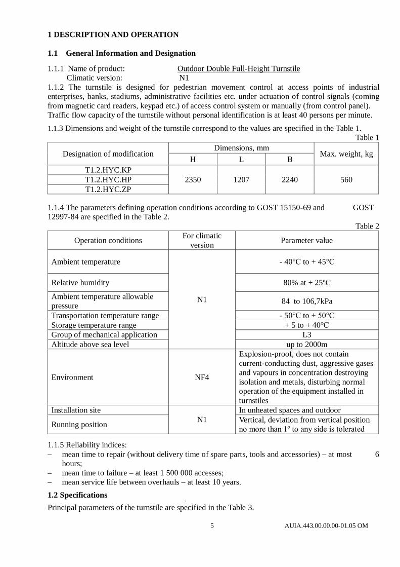
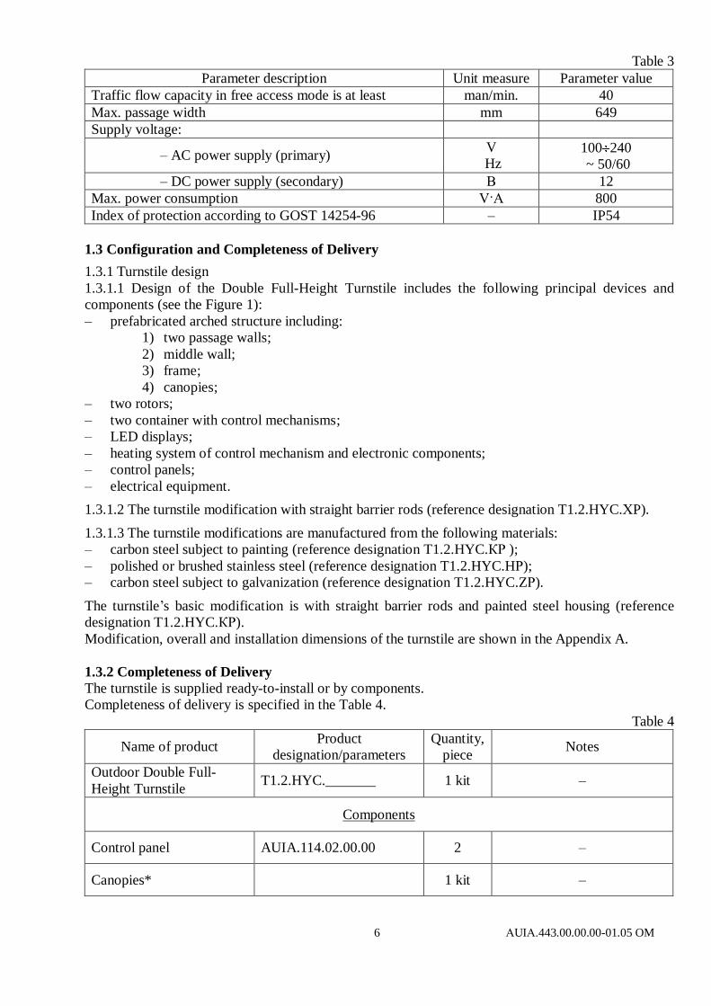
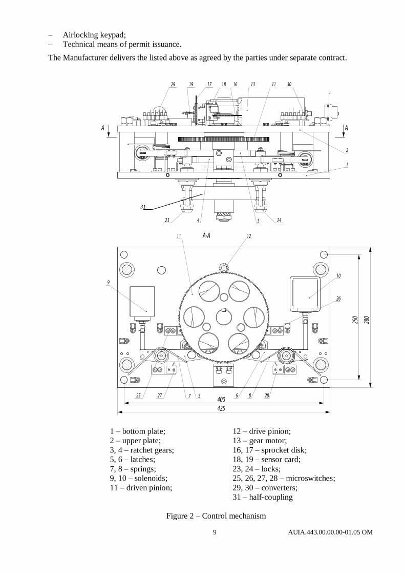
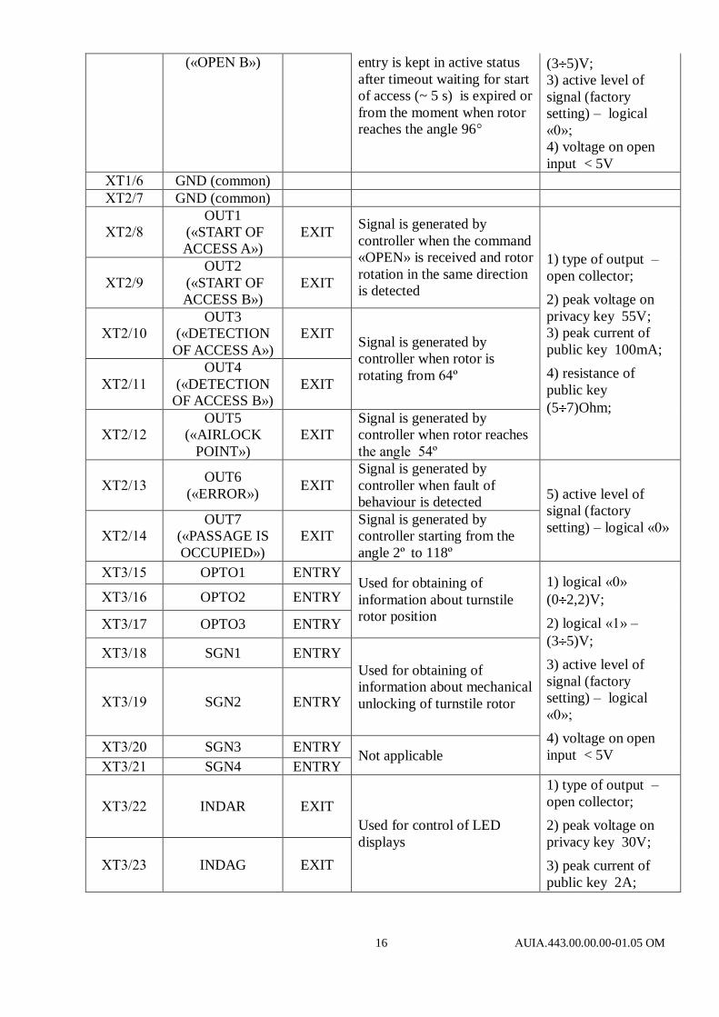
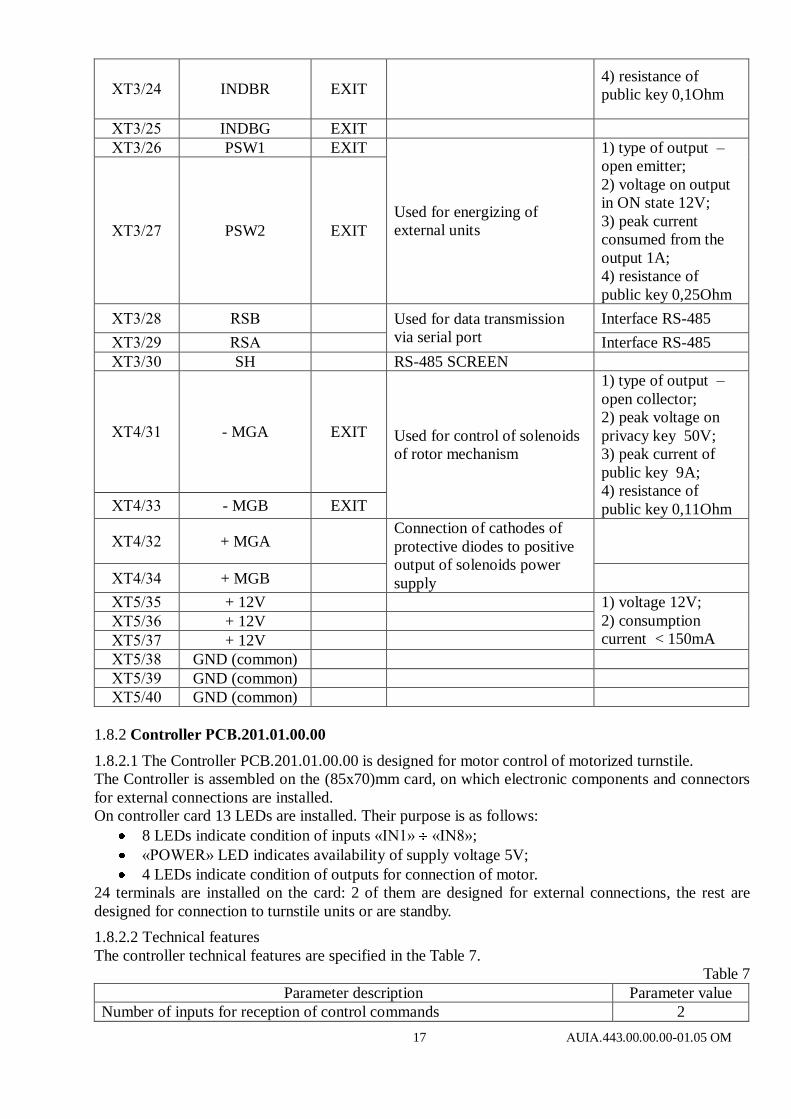
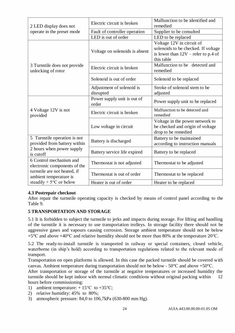
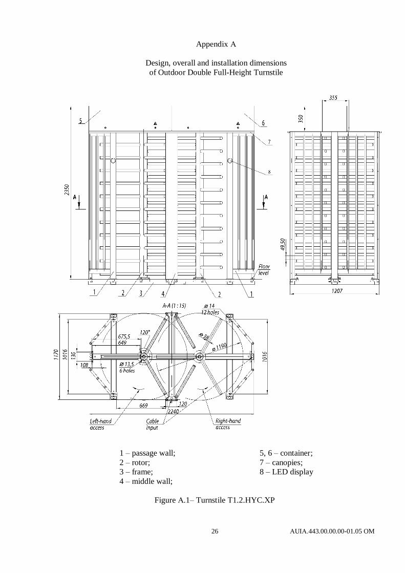

28 АUIА443000000-0105 OM
Appendix B (continued)
Control panel and connection diagram
Figure B2 ndash Connection diagram of the control panel
AUIA114020000
Appendix C
Wiring Diagram of the turnstile
Figure C1 ndash Wiring Diagram of each passageway of the turnstile with servomotor

Appendix C
Wiring Diagram of the turnstile
Figure C1 ndash Wiring Diagram of each passageway of the turnstile with servomotor