our path to a runningour path to a running experiment and ...cindro/seminars/olav.pdf · our path...
TRANSCRIPT
The LHCb Experiment.
Our Path to a RunningOur Path to a Running Experiment
and what comes after.O. UllalandLjubljana January 2008
1Theodor Kittelsen, Soria Moria (with modifications)
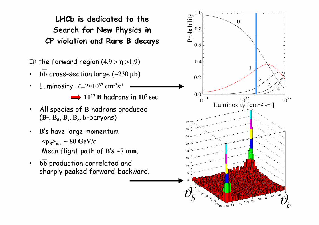
LHCb is dedicated to the Search for New Physics in
In the forward region (4 9 > η >1 9):
CP violation and Rare B decays
In the forward region (4.9 > η >1.9):
• bb cross-section large (∼230 μb)
• Luminosity ℒ=2∗1032 cm-2s-1Luminosity ℒ=2∗10 cm s1012 B hadrons in 107 sec
• All species of B hadrons producedp p(B±, Bd, Bs, Bc, b-baryons)
• B’s have large momentum<pB>acc ~ 80 GeV/cMean flight path of B’s ∼7 mm.
• bb production correlated and• bb production correlated and sharply peaked forward-backward.
ϑ2 bϑbϑ
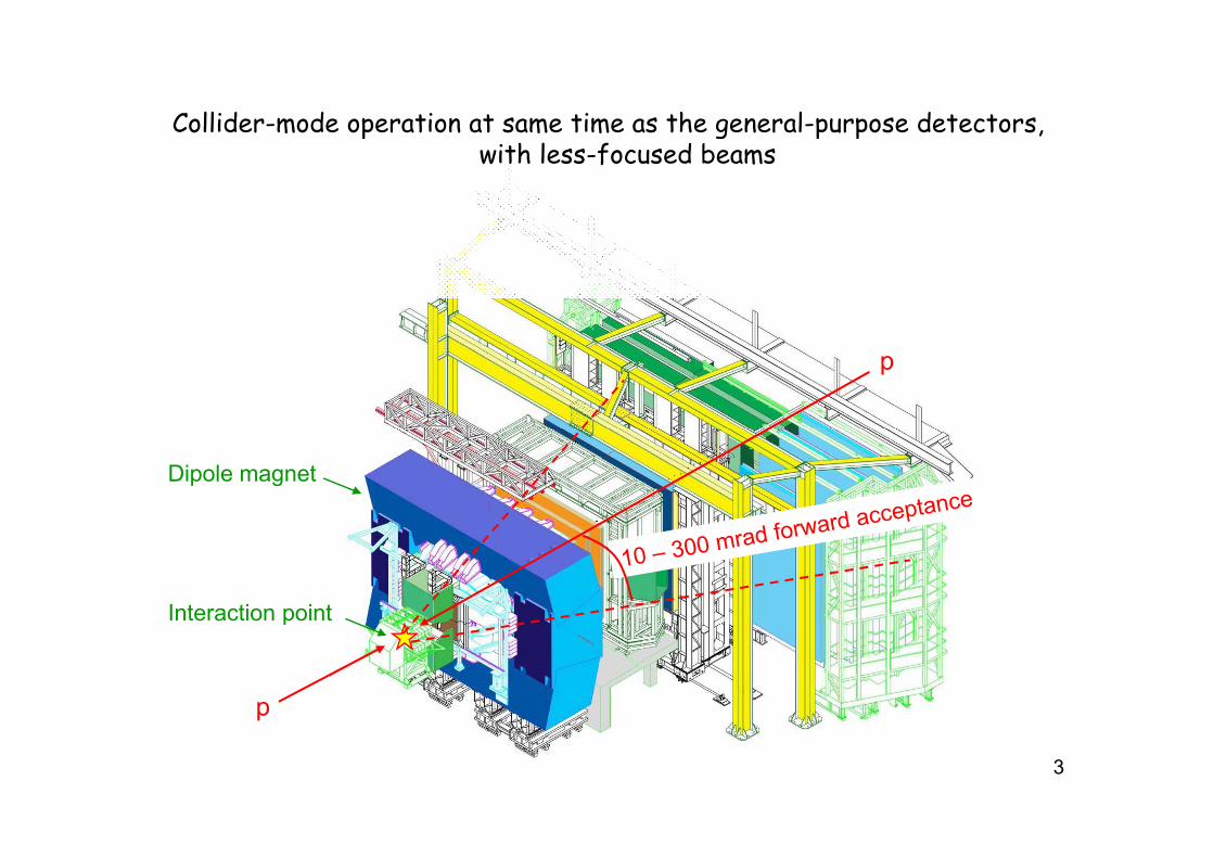
Collider-mode operation at same time as the general-purpose detectors,p g p pwith less-focused beams
p
Dipole magnet
Interaction point
p
p
3
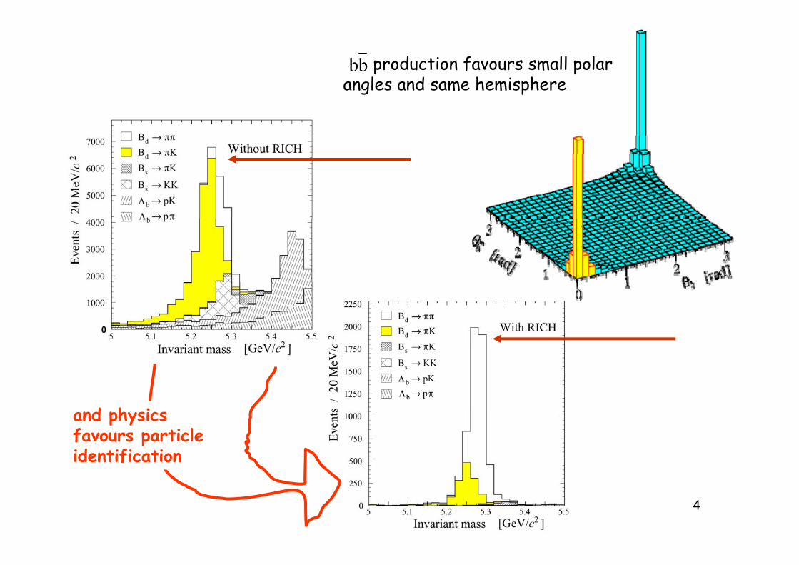
production favours small polar angles and same hemisphere
bbangles and same hem sphere
d h iand physics favours particle identification
4
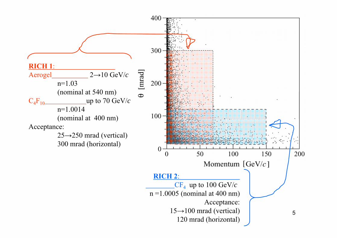
RICH 1RICH 1: Aerogel 2→10 GeV/c
n=1.03 (nominal at 540 nm)(nominal at 540 nm)
C4F10 up to 70 GeV/cn=1.0014 (nominal at 400 nm)(nominal at 400 nm)
Acceptance: 25→250 mrad (vertical) 300 mrad (horizontal)300 mrad (horizontal)
RICH 2: CF4 up to 100 GeV/c
n =1.0005 (nominal at 400 nm)A
5
Acceptance: 15→100 mrad (vertical)
120 mrad (horizontal)
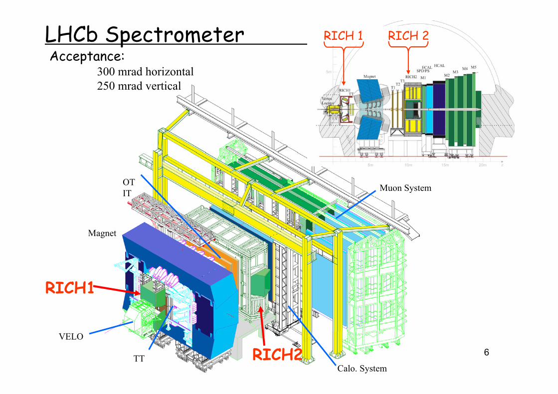
LHCb SpectrometerAcceptance:
RICH 1 RICH 2p
300 mrad horizontal250 mrad vertical
OTIT Muon System
Magnet
RICH1RICH1
6
VELO
TT RICH2Calo. System
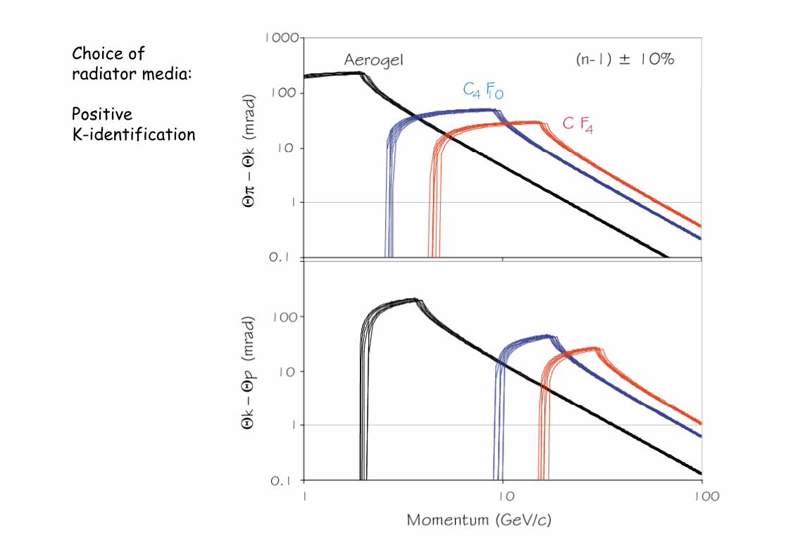
Choice of radiator media:
Positive K-identification
7
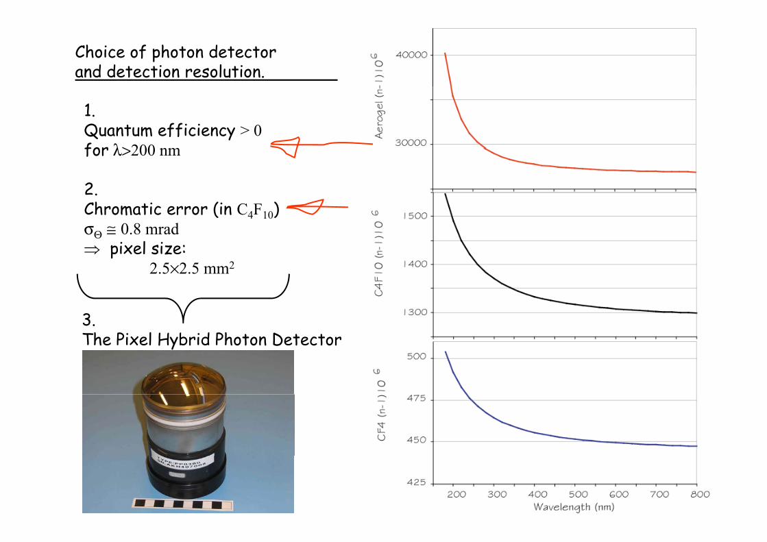
Choice of photon detector and detection resolution.
1.Quantum efficiency > 0for λ>200 nmfor λ>200 nm
2.Chromatic error (in C F )Chromatic error (in C4F10)σΘ ≅ 0.8 mrad⇒ pixel size:
2 5×2 5 mm22.5×2.5 mm
3.h P l b d PhThe Pixel Hybrid Photon Detector
8
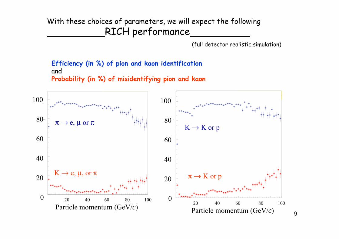
With these choices of parameters, we will expect the following RICH performance
(full detector realistic simulation)
Efficiency (in %) of pion and kaon identificationEfficiency (in %) of pion and kaon identificationand Probability (in %) of misidentifying pion and kaon
80
100
80
100
π → e, μ or π
60
80K → K or p
60
80
K → e μ or π
40
K
40
K → e, μ, or π
20 40 60 80 1000
20 π → K or p
0
20
9
20 40 60 80 100
Particle momentum (GeV/c)0
20 40 60 80 100
Particle momentum (GeV/c)
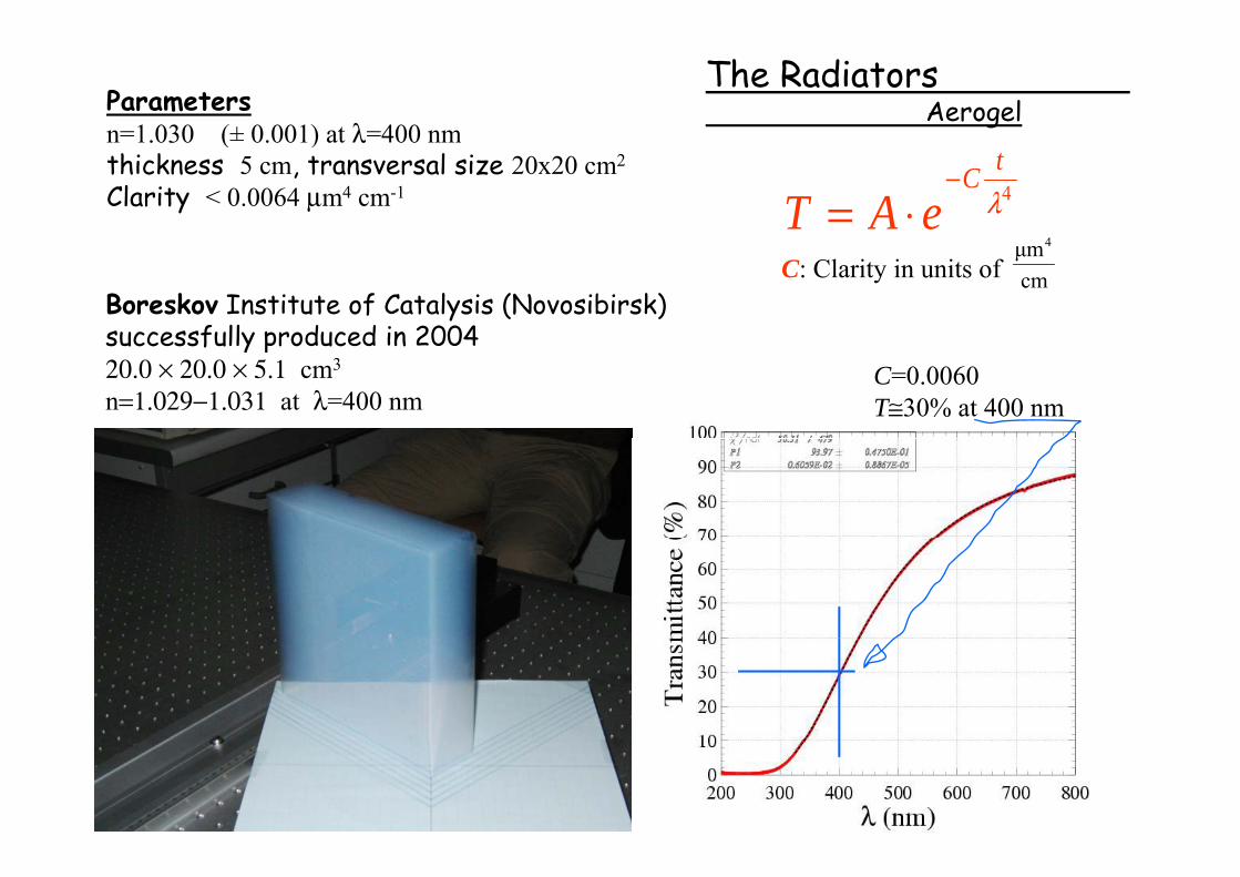
The RadiatorsAerogelParameters
n=1.030 (± 0.001) at λ=400 nmn 1.030 (± 0.001) at λ 400 nmthickness 5 cm, transversal size 20x20 cm2
Clarity < 0.0064 μm4 cm-1 4λtC
eAT−
⋅=4
C: Clarity in units of cmμm4
Boreskov Institute of Catalysis (Novosibirsk)successfully produced in 2004successfully produced in 200420.0 × 20.0 × 5.1 cm3
n=1.029−1.031 at λ=400 nmC=0.0060T≅30% at 400 nm
10
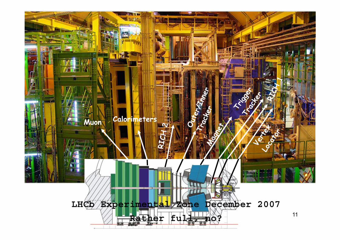
CalorimetersM CalorimetersMuon
LHCb E i t l Z D b 200711
LHCb Experimental Zone December 2007
Rather full, no?
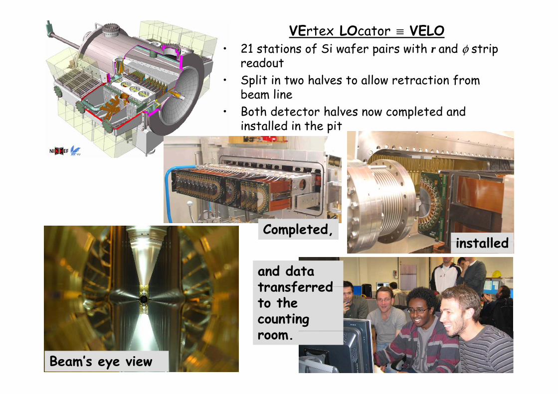
VErtex LOcator ≡ VELO• 21 stations of Si wafer pairs with r and φ strip
readoutreadout• Split in two halves to allow retraction from
beam lineB th d t t h l l t d d• Both detector halves now completed and installed in the pit
Completed,installed
and data transferred
installed
transferred to the counting
12Beam’s eye view
room.
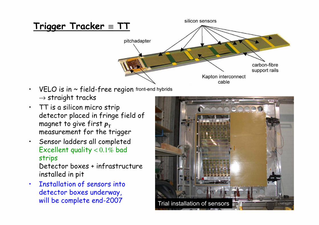
Trigger Tracker ≡ TT
VELO i i fi ld f i• VELO is in ~ field-free region→ straight tracks
• TT is a silicon micro strip d l d f f ld fdetector placed in fringe field of magnet to give first pTmeasurement for the trigger
• Sensor ladders all completedExcellent quality < 0.1% bad stripsD b i fDetector boxes + infrastructure installed in pit
• Installation of sensors into
13detector boxes underway,will be complete end-2007 Trial installation of sensors
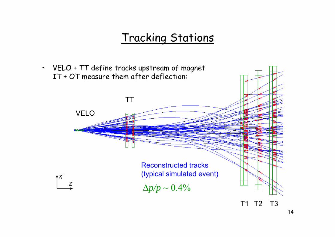
Tracking StationsTracking Stations
E d f k f• VELO + TT define tracks upstream of magnetIT + OT measure them after deflection:
VELO
TT
B-field ⊗
Inner Tracker: silicon micro stripsReconstructed tracks(t i l i l t d t)Inner Tracker: silicon micro strips
2% of area but 20% of tracks
Outer Tracker: 5mm straw tubes
(typical simulated event)xz Δp/p ~ 0.4%
14T1 T2 T3
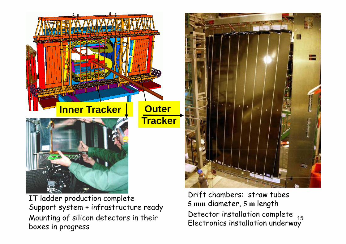
Outer Tracker
Inner Tracker Tracker
Drift chambers: straw tubes5 mm diameter 5 m length
IT ladder production completeS t t i f t t d
15
5 mm diameter, 5 m length Detector installation completeElectronics installation underway
Support system + infrastructure readyMounting of silicon detectors in their boxes in progress
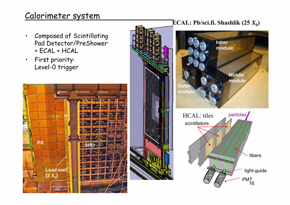
ECAL: Pb/sci.fi. Shashlik (25 X0)Calorimeter system
• Composed of ScintillatingPad Detector/PreShower+ ECAL + HCAL
Inner module
• First priority: Level-0 trigger
Middle d lmodule
Outermodule
particles
scintillatorsHCAL: tiles
SPDPS
Lead wall
fibers
light-guide
16(2 X0) PMT
g g
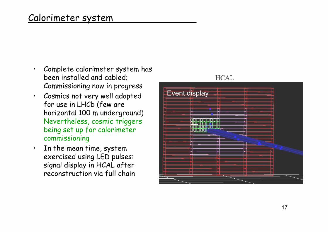
Calorimeter system
• Complete calorimeter system has been installed and cabled;Commissioning now in progressg p g
• Cosmics not very well adapted for use in LHCb (few are horizontal 100 m underground)
Event display
g )Nevertheless, cosmic triggers being set up for calorimeter commissioningg
• In the mean time, system exercised using LED pulses:signal display in HCAL after g p yreconstruction via full chain
17
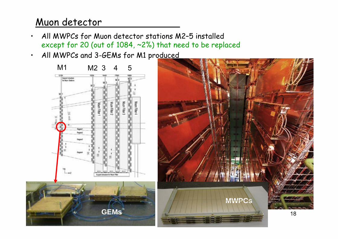
• All MWPCs for Muon detector stations M2–5 installed
Muon detectorAll MWPCs for Muon detector stations M2 5 installedexcept for 20 (out of 1084, ~2%) that need to be replaced
• All MWPCs and 3-GEMs for M1 producedM1 M2 3 4M1 M2 3 4 5
MWPCs18GEMs
MWPCs
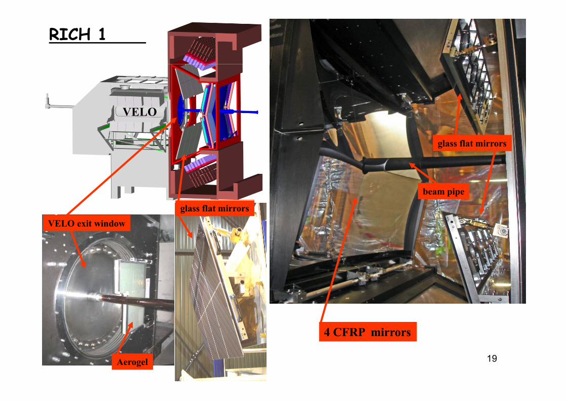
RICH 1
VELO
glass flat mirrors
VELO
beam pipe
glass flat mirrorsVELO exit window
4 CFRP mirrors
19Aerogel
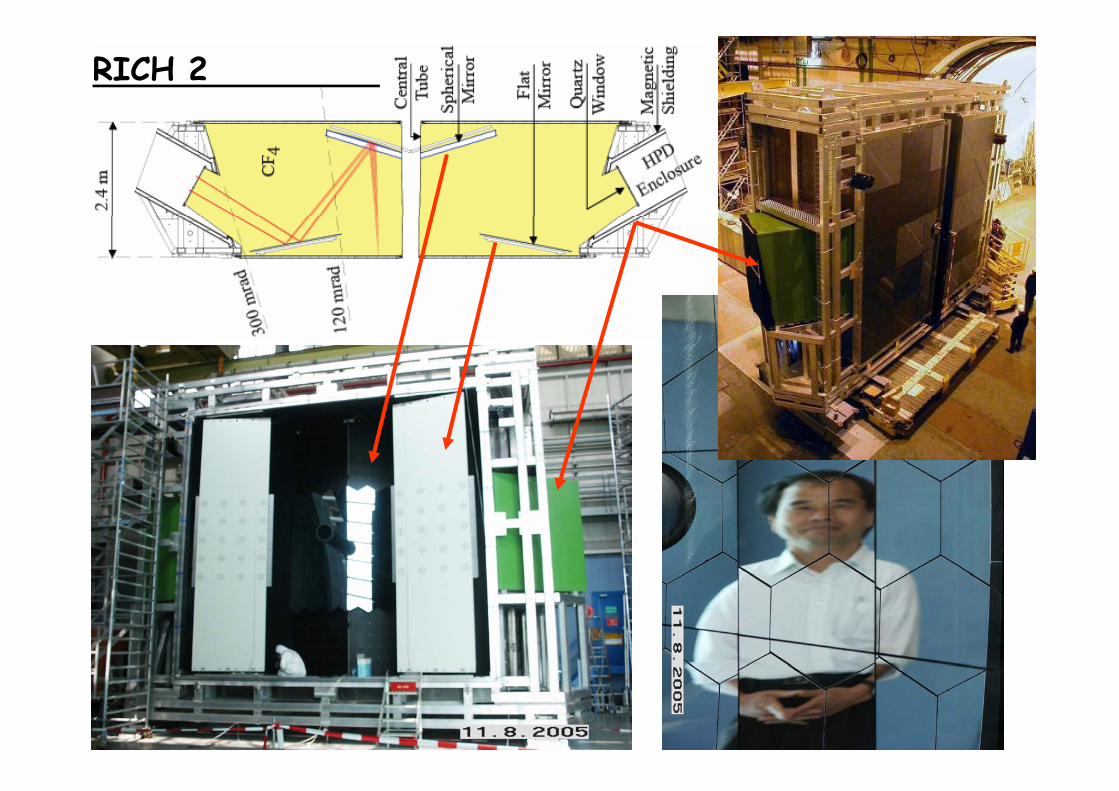
RICH 2
20
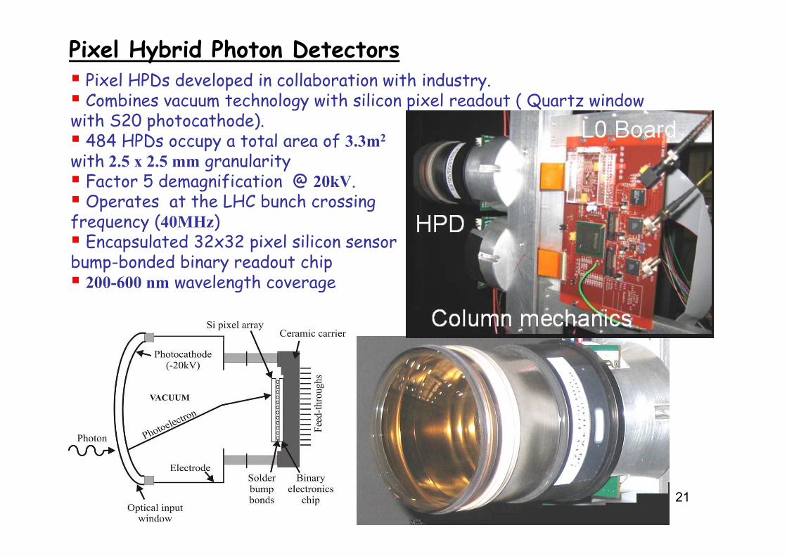
Pixel Hybrid Photon DetectorsPixel HPDs developed in collaboration with industry.p yCombines vacuum technology with silicon pixel readout ( Quartz window
with S20 photocathode). 484 HPDs occupy a total area of 3.3m2
with 2.5 x 2.5 mm granularityFactor 5 demagnification @ 20kV.Operates at the LHC bunch crossing
f ( )frequency (40MHz)Encapsulated 32x32 pixel silicon sensor
bump-bonded binary readout chip200 600 l th200-600 nm wavelength coverage
21
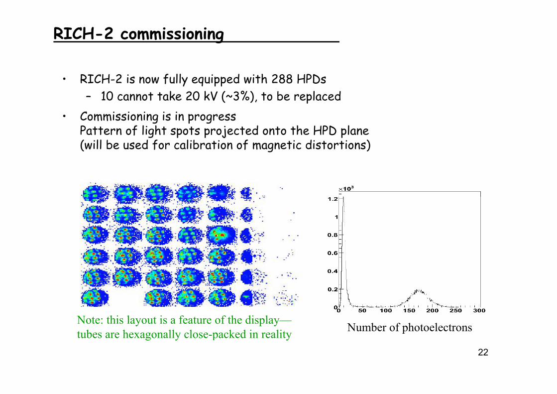
RICH-2 commissioning
• RICH-2 is now fully equipped with 288 HPDs– 10 cannot take 20 kV (~3%), to be replaced
• Commissioning is in progressPattern of light spots projected onto the HPD plane(will be used for calibration of magnetic distortions)
Note: this layout is a feature of the display—t b h ll l k d i lit Number of photoelectrons
22
tubes are hexagonally close-packed in reality Nu be o p otoe ect o s
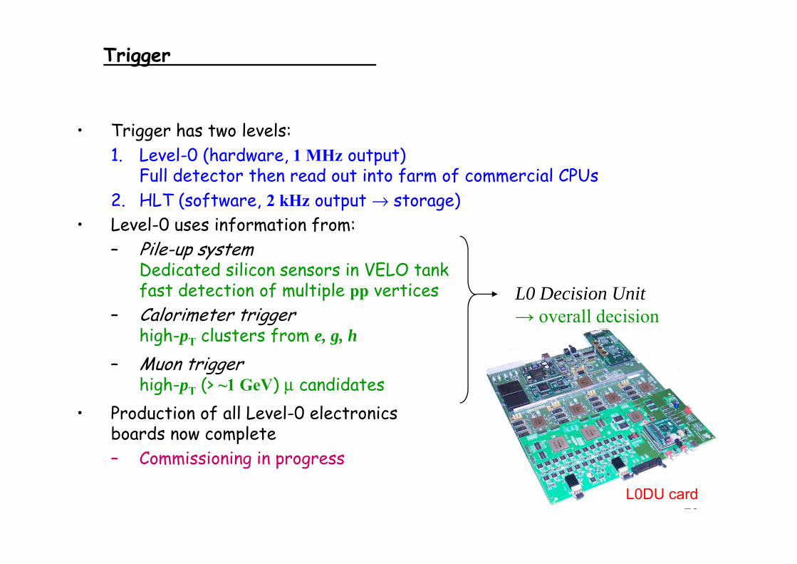
Trigger
• Trigger has two levels:1 Level 0 (hardware 1 MHz output)1. Level-0 (hardware, 1 MHz output)
Full detector then read out into farm of commercial CPUs2. HLT (software, 2 kHz output → storage)L l 0 i f i f• Level-0 uses information from: – Pile-up system
Dedicated silicon sensors in VELO tankfast detection of multiple pp vertices
– Calorimeter triggerhigh-pT clusters from e, g, h
L0 Decision Unit→ overall decision
– Muon triggerhigh-pT (> ~1 GeV) μ candidates
P ducti n f ll L l 0 l ct nics• Production of all Level-0 electronics boards now complete– Commissioning in progress
23L0DU card
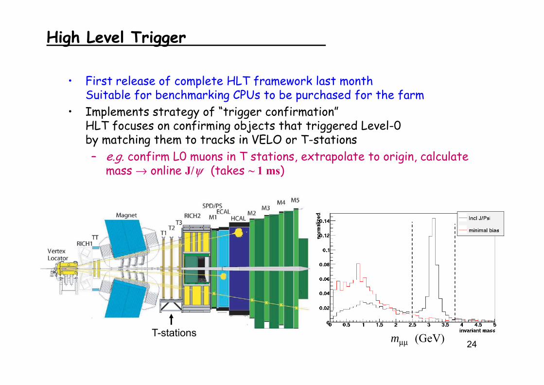
High Level Trigger
• First release of complete HLT framework last monthSuitable for benchmarking CPUs to be purchased for the farm
• Implements strategy of “trigger confirmation”HLT focuses on confirming objects that triggered Level-0 by matching them to tracks in VELO or T-stations– e.g. confirm L0 muons in T stations, extrapolate to origin, calculate
mass → online J/ψ (takes ~ 1 ms)
24mμμ (GeV)T-stations
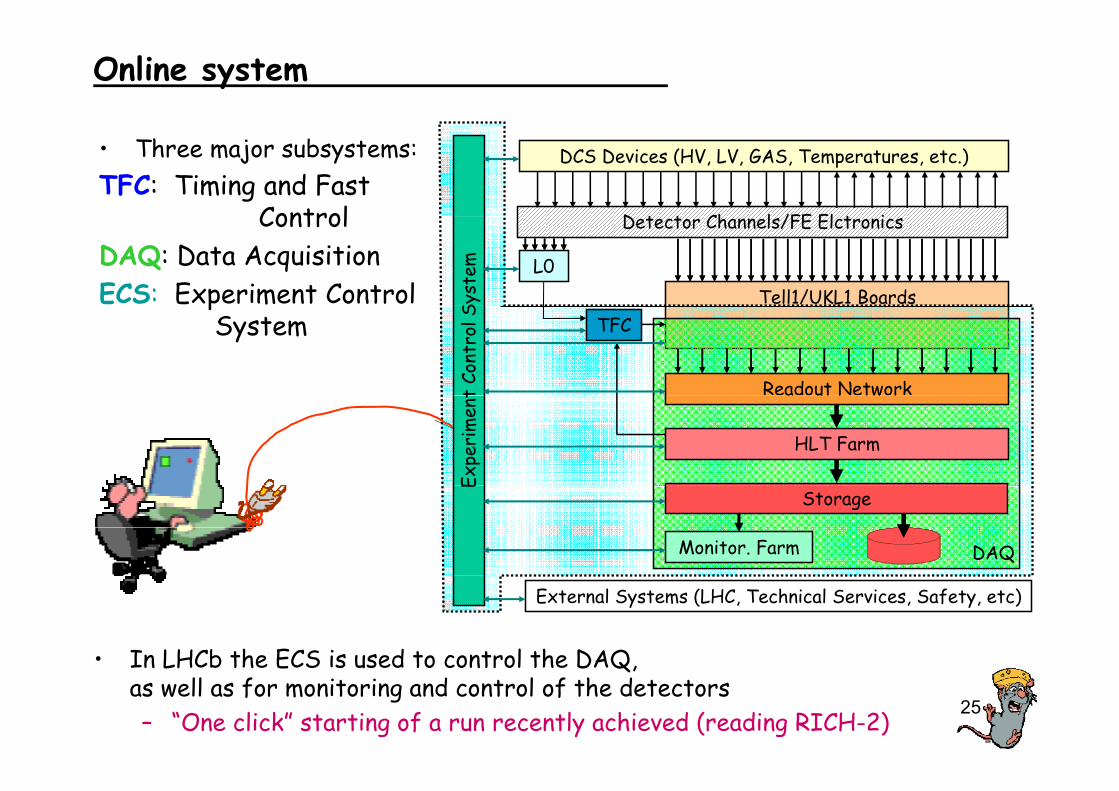
Online system
• Three major subsystems:TFC: Timing and Fast
Control D t t Ch l /FE El t i
DCS Devices (HV, LV, GAS, Temperatures, etc.)
ControlDAQ: Data AcquisitionECS: Experiment Control Tell1/UKL1 Boards
Detector Channels/FE Elctronics
L0
Syst
em
pSystem
t Co
ntro
l S TFC
Readout Network
Expe
rim
ent a ut N tw r
HLT FarmE
Storage
DAQMonitor. Farm
External Systems (LHC, Technical Services, Safety, etc)
• In LHCb the ECS is used to control the DAQ
25
In LHCb the ECS is used to control the DAQ, as well as for monitoring and control of the detectors– “One click” starting of a run recently achieved (reading RICH-2)

RICH Upgrade Plans.a personal view.
Never ask a RICHer to improve the flawless!
26Excuse me, BC!
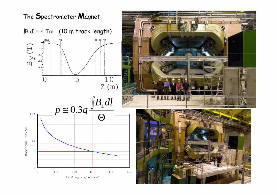
The Spectrometer Magnet
∫B dl = 4 Tm (10 m track length)∫B dl = 4 Tm (10 m track length)
∫100 Θ
≅ ∫ ⊥dlBqp 3.0
10m (GeV/c)
Θ
Momentum
271
0 0.1 0.2 0.3 0.4 0.5
Bending angle (rad)
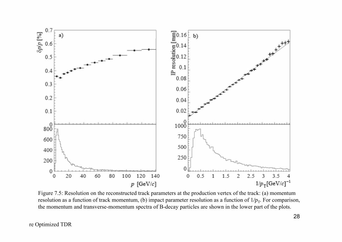
Figure 7.5: Resolution on the reconstructed track parameters at the production vertex of the track: (a) momentum resolution as a function of track momentum, (b) impact parameter resolution as a function of 1/pT. For comparison,
28
the momentum and transverse-momentum spectra of B-decay particles are shown in the lower part of the plots.
re Optimized TDR
/ mm
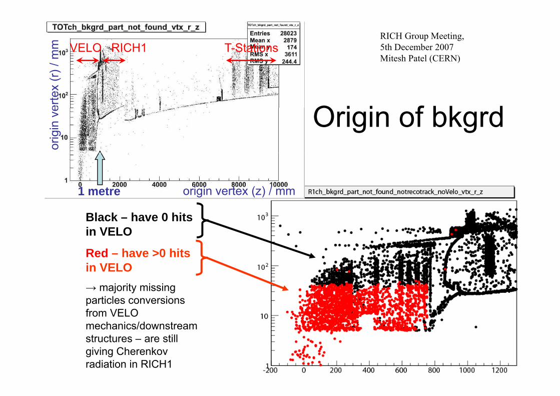
VELO RICH1 T-Stations
RICH Group Meeting, 5th December 2007Mitesh Patel (CERN)
erte
x (r
) /
O i i f bk d
( )or
igin
ve Origin of bkgrd
origin vertex (z) / mm 1 metre
Black – have 0 hits in VELO
Red – have >0 hits in VELO→ majority missing→ majority missing particles conversions from VELO mechanics/downstream
29structures – are still giving Cherenkov radiation in RICH1
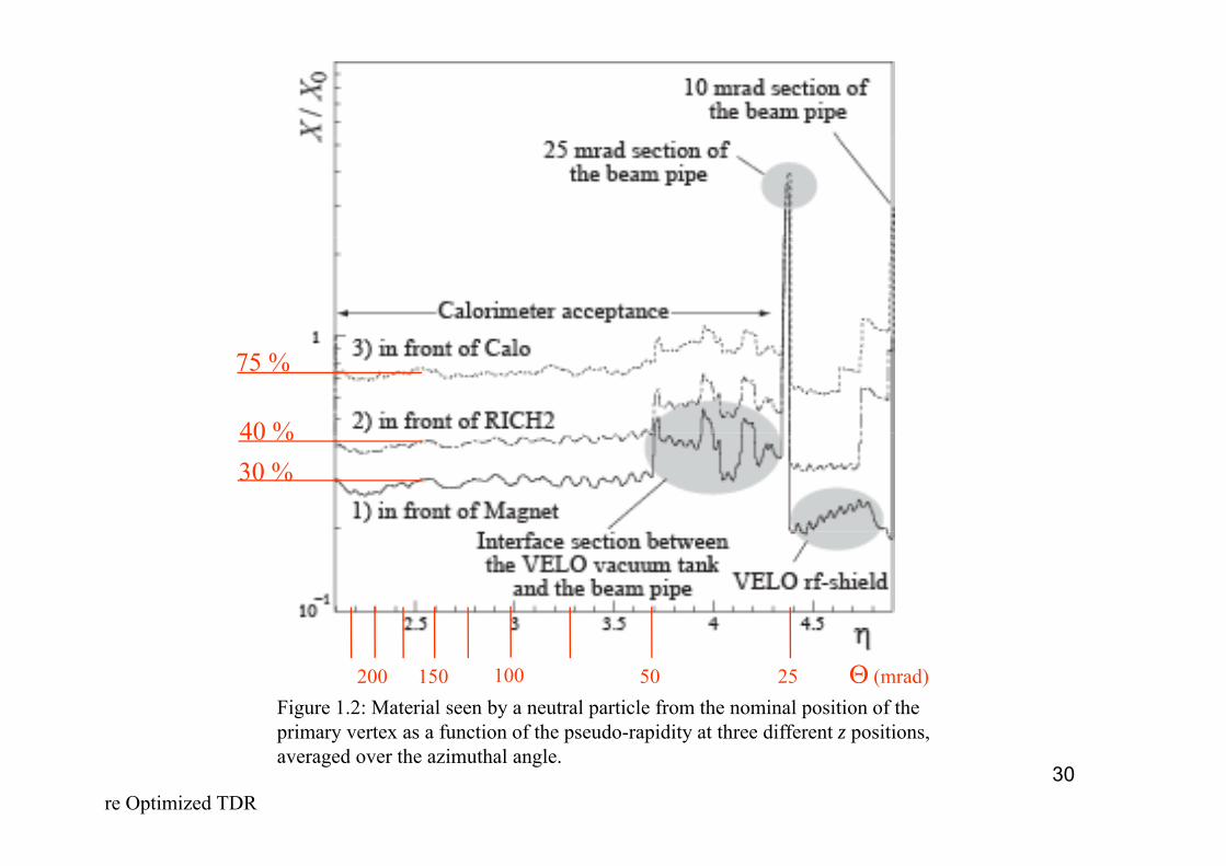
40 %
75 %
30 %40 %
Figure 1.2: Material seen by a neutral particle from the nominal position of the i t f ti f th d idit t th diff t iti
200 150 100 50 25 Θ (mrad)
30
primary vertex as a function of the pseudo-rapidity at three different z positions, averaged over the azimuthal angle.
re Optimized TDR

From the LHCb Upgrade Working Group:
The main idea is to upgrade the LHCb experiment such that it can operate at 10 times the design luminosity, i.e. at ~2x1033 cm-2s-1 and collect a data sample of ~100 fb-1mp f
What is the impact of switching to a 40 MHz read-out?
We also need to produce an R&D plan for the different subsystems, i.e what is happening already, and what is actually required for LHCb upgrade. upg .
There is growing international consensus that futureg g fflavour physics experiments will be required in thesecond half of the next decade toeither- study the flavour structure of new particlesdiscovered at the LHCor
31- to probe new physics at the multi-TeV scale.
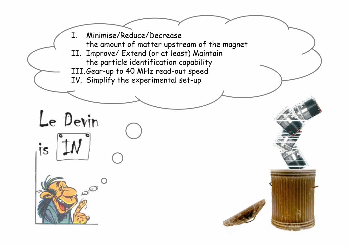
I. Minimise/Reduce/Decreasethe amount of matter upstream of the magnet
II. Improve/ Extend (or at least) Maintain the particle identification capability
III.Gear-up to 40 MHz read-out speedIV. Simplify the experimental set-up
32
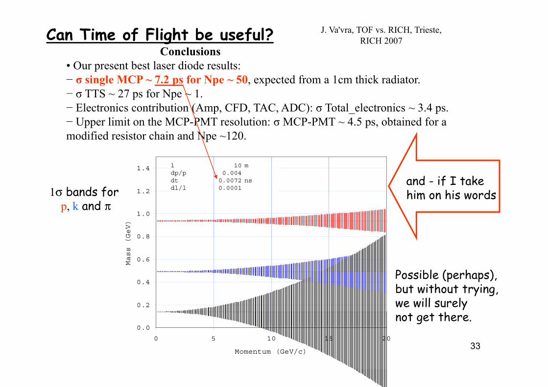
ConclusionsO b l di d l
J. Va'vra, TOF vs. RICH, Trieste,RICH 2007Can Time of Flight be useful?
• Our present best laser diode results:− σ single MCP ~ 7.2 ps for Npe ~ 50, expected from a 1cm thick radiator.− σ TTS ~ 27 ps for Npe ~ 1.
El t i t ib ti (A CFD TAC ADC) T t l l t i 3 4− Electronics contribution (Amp, CFD, TAC, ADC): σ Total_electronics ~ 3.4 ps.− Upper limit on the MCP-PMT resolution: σ MCP-PMT ~ 4.5 ps, obtained for amodified resistor chain and Npe ~120.
1.2
1.4 l 10 mdp/p 0.004dt 0.0072 nsdl/l 0.00011σ bands for
and - if I take him on his words
0 8
1.0
GeV)
1σ bands for p, k and π
him on his words
0 4
0.6
0.8
Mass (G
Possible (perhaps),
0.2
0.4p p
but without trying,we will surelynot get there.
33
0.0
0 5 10 15 20
Momentum (GeV/c)
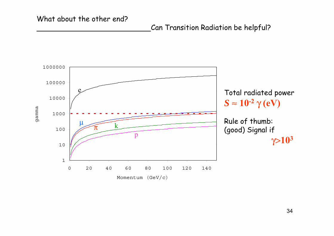
What about the other end?Can Transition Radiation be helpful?
100000
1000000
e T t l di t d p
1000
10000
amma
e Total radiated powerS ≈ 10-2 γ (eV)
l
10
100
ga
μπ
pk Rule of thumb:
(good) Signal if γ>103
1
10
0 20 40 60 80 100 120 140
γ
Momentum (GeV/c)
34
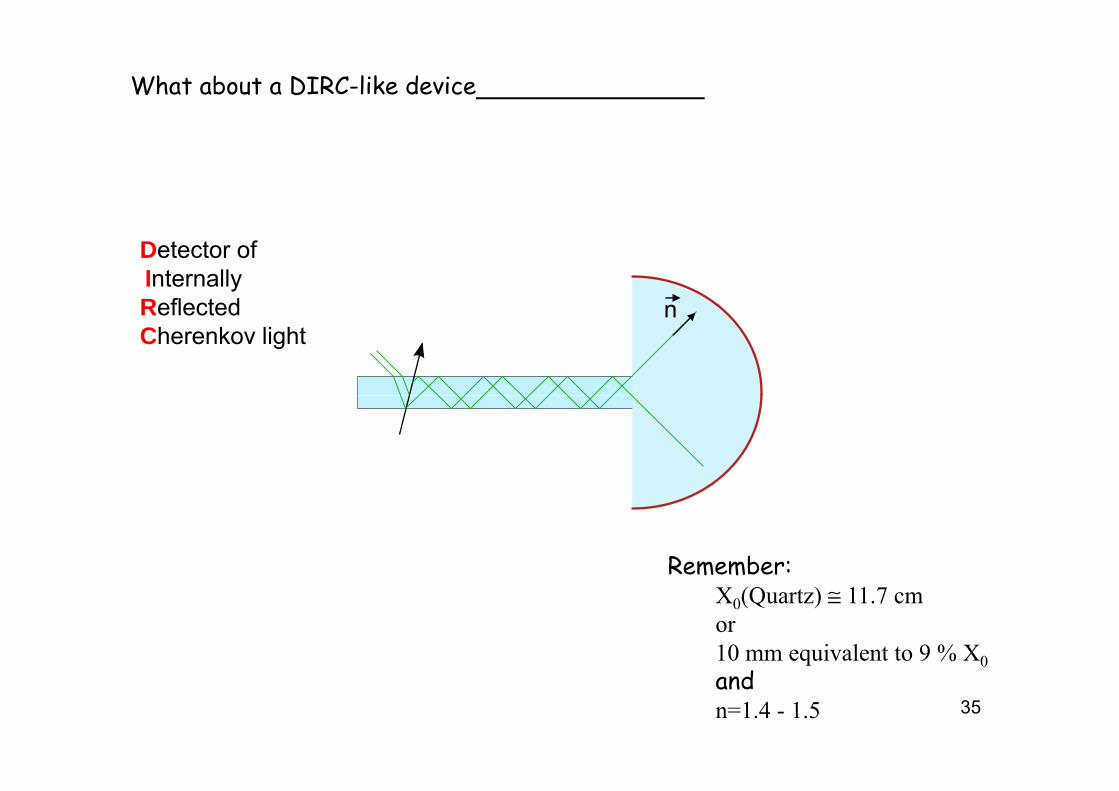
What about a DIRC-like device
Detector ofInternallyReflected nReflectedCherenkov light
n
Remember:m mX0(Quartz) ≅ 11.7 cmor 10 mm equivalent to 9 % X0
35
q 0andn=1.4 - 1.5
Have another look at a "mature" work horse in particle identification:
TheThe
36But no liquid radiators, please! I have worked in DELPHI!!
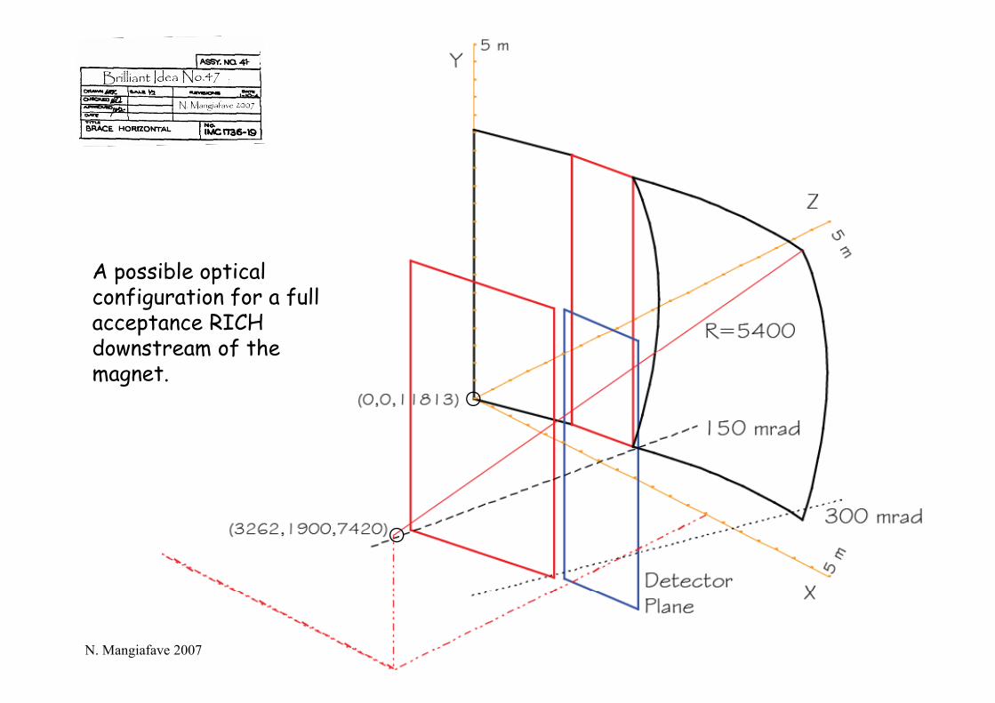
A possible opticalA possible optical configuration for a full acceptance RICH downstream of thedownstream of the magnet.
37N. Mangiafave 2007
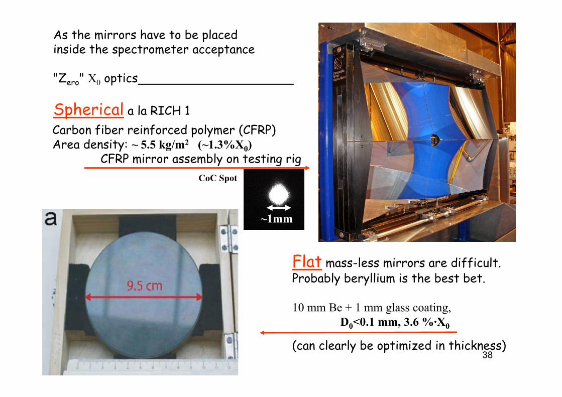
As the mirrors have to be placed inside the spectrometer acceptance
"Zero" X0 optics
Spherical l RICH 1Spherical a la RICH 1Carbon fiber reinforced polymer (CFRP)Area density: ~ 5.5 kg/m2 (~1.3%X0)
lCFRP mirror assembly on testing rigCoC Spot
~1mm
Flat mass-less mirrors are difficult.Probably beryllium is the best bet.
10 mm Be + 1 mm glass coating, D0<0.1 mm, 3.6 %·X0
38(can clearly be optimized in thickness)
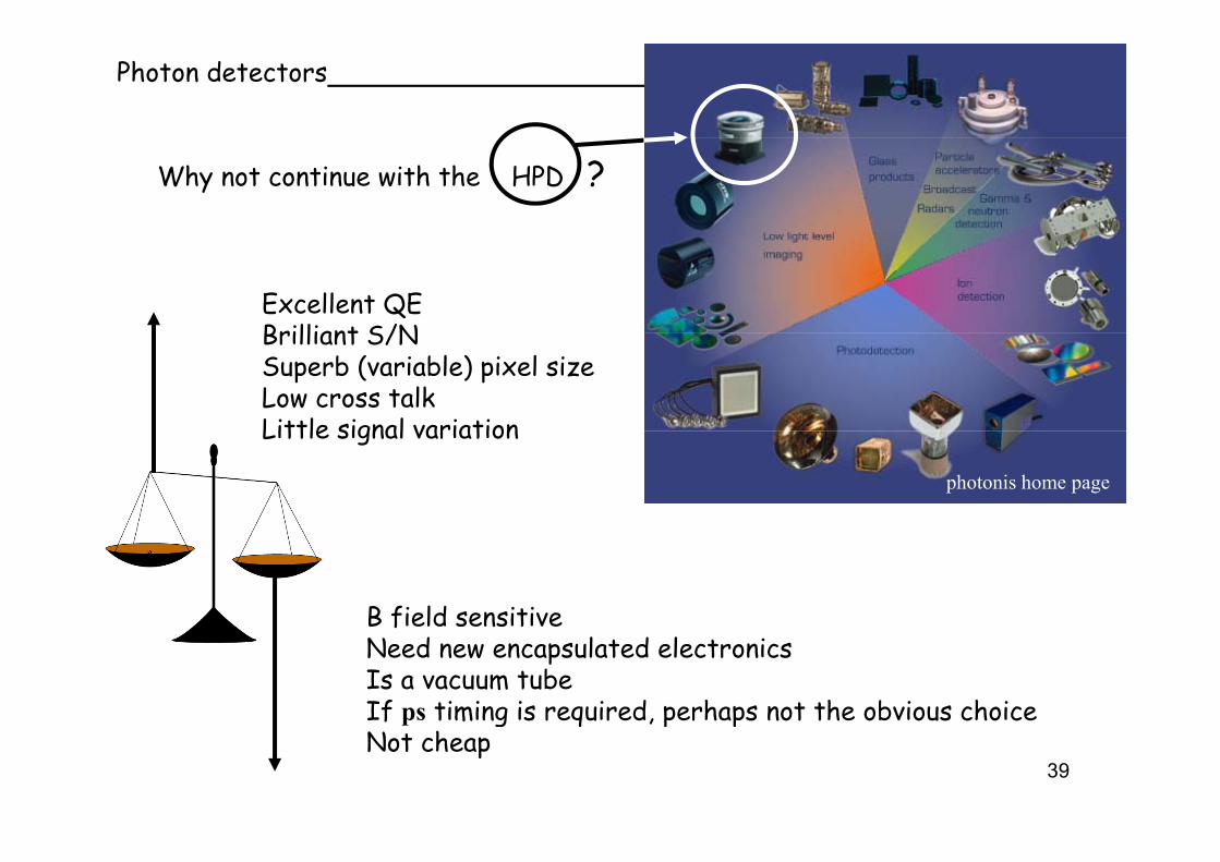
Photon detectors
Why not continue with the HPD ?
Excellent QEBrilliant S/NBrilliant S/NSuperb (variable) pixel sizeLow cross talkLittle signal variationLittle signal variation
photonis home page
B field sensitivef nNeed new encapsulated electronicsIs a vacuum tubeIf ps timing is required, perhaps not the obvious choice
39
p g q p pNot cheap
U til th i t bli h d d fi d I ld till l t d40
Until otherwise proven, established and confirmed, I would still lean towards HPD-like photon detectors for a RICH detector.
(but Micro Channel Plates looks cute!)
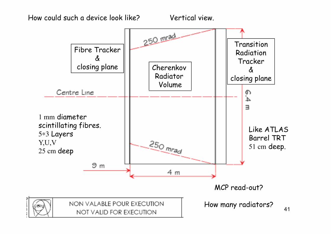
How could such a device look like? Vertical view.
Fibre Tracker&
l l
TransitionRadiationTracker
Cherenkov Radiator Volume
closing plane &closing plane
1 mm diameter
Like ATLAS Barrel TRT
d
1 mm diameter scintillating fibres.5∗3 LayersYU V 51 cm deep.Y,U,V25 cm deep
MCP read-out?
41How many radiators?
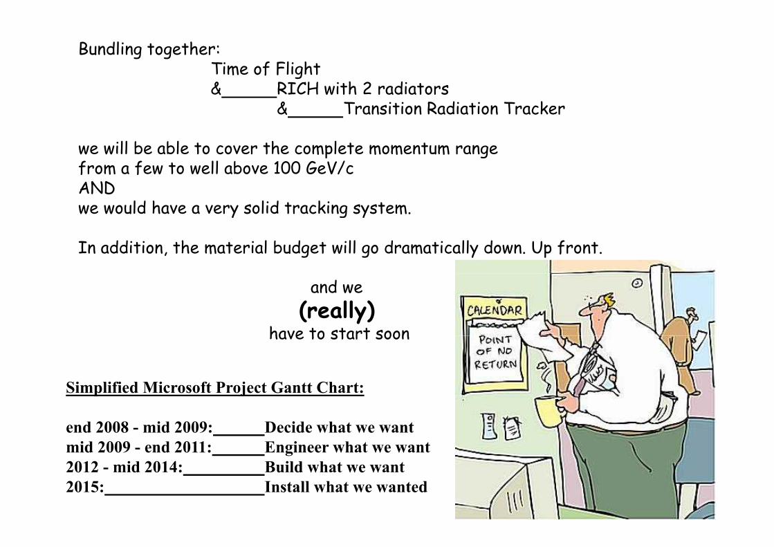
Bundling together:Time of Flight& RICH with 2 radiators& RICH with 2 radiators
& Transition Radiation Tracker
we will be able to cover the complete momentum rangewe will be able to cover the complete momentum rangefrom a few to well above 100 GeV/cANDwe would have a very solid tracking systemwe would have a very solid tracking system.
In addition, the material budget will go dramatically down. Up front.
and we (really)
have to start soonhave to start soon
Simplified Microsoft Project Gantt Chart:
end 2008 - mid 2009: Decide what we wantmid 2009 - end 2011: Engineer what we want
422012 - mid 2014: Build what we want 2015: Install what we wanted
Many thanks to
Valerie Gibson, Lake Louise Winter Institute 2007Roger Forty, LHCC 21 November 2007Roger Forty, LHCC 21 November 2007Fabio Metlica, RICH 2007Thierry Gys, RICH 2007C l D'A b i RICH 2007Carmelo D'Ambrosio, RICH 2007
from whom I have borrowed, stolen or lifted a number of transparencies.p
43
Spare Slide(s)p ( )
44