osicoder - rotary encoders catalogue 2006.01
TRANSCRIPT
Rotary encodersOsicoder®
06CatalogueJanuary

1
Contents 0 Rotary encoders Osicoder®
1
b General . . . . . . . . . . . . . . . . . . . . . . . . . . . . . . . . . . . . . . . . . . . . . . . . . . . . page 2
Selection guide . . . . . . . . . . . . . . . . . . . . . . . . . . . . . . . . . . . . . . . . . . . . . . .page 8
Incremental encodersb Ø 40 mm incremental encoders
v Characteristics, schemes. . . . . . . . . . . . . . . . . . . . . . . . . . . . . . . . . . . . page 10
v References . . . . . . . . . . . . . . . . . . . . . . . . . . . . . . . . . . . . . . . . . . . . . . page 11
v Dimensions, connections. . . . . . . . . . . . . . . . . . . . . . . . . . . . . pages 18 and 19
b Ø 58 mm incremental encoders and parameterable versions
v Characteristics, schemes. . . . . . . . . . . . . . . . . . . . . . . . . . . . . . . . . . . . page 12
v References . . . . . . . . . . . . . . . . . . . . . . . . . . . . . . . . . . . . . . . . pages 13 to 15
v Dimensions, connections. . . . . . . . . . . . . . . . . . . . . . . . . . . . . pages 18 and 19
b Ø 90 mm incremental encoders
v Characteristics, schemes. . . . . . . . . . . . . . . . . . . . . . . . . . . . . . . . . . . . page16
v References . . . . . . . . . . . . . . . . . . . . . . . . . . . . . . . . . . . . . . . . . . . . . . page17
v Dimensions, connections. . . . . . . . . . . . . . . . . . . . . . . . . . . . . pages 18 and 19
Single turn absolute encodersb Ø 58 mm single turn absolute encoders
v Characteristics, schemes . . . . . . . . . . . . . . . . . . . . . . . . . . . . . . . . . . . page 20
v References . . . . . . . . . . . . . . . . . . . . . . . . . . . . . . . . . . . . . . . . . . . . . . page 21
v Dimensions, connections. . . . . . . . . . . . . . . . . . . . . . . . . . . . . pages 24 and 25
b Ø 90 mm single turn absolute encoders
v Characteristics, schemes. . . . . . . . . . . . . . . . . . . . . . . . . . . . . . . . . . . . page 22
v References . . . . . . . . . . . . . . . . . . . . . . . . . . . . . . . . . . . . . . . . . . . . . . page 23
v Dimensions, connections. . . . . . . . . . . . . . . . . . . . . . . . . . . . . pages 24 and 25
Multiturn absolute encodersb Ø 58 mm multiturn absolute encoders
v Characteristics, schemes. . . . . . . . . . . . . . . . . . . . . . . . . . . . . . . . . . . . page 26
v References . . . . . . . . . . . . . . . . . . . . . . . . . . . . . . . . . . . . . . . . . . . . . . page 27
v Dimensions, connections. . . . . . . . . . . . . . . . . . . . . . . . . . . . . . pages 30 to 33
b Ø 90 mm multiturn absolute encoders
v Characteristics, schemes. . . . . . . . . . . . . . . . . . . . . . . . . . . . . . . . . . . . page 28
v References . . . . . . . . . . . . . . . . . . . . . . . . . . . . . . . . . . . . . . . . . . . . . . page 29
v Dimensions, connections. . . . . . . . . . . . . . . . . . . . . . . . . . . . . . pages 30 to 33
Accessories b for incremental, single turn and multiturn encoders
v Characteristics . . . . . . . . . . . . . . . . . . . . . . . . . . . . . . . . . . . . . . . . . . . . page 34
v References . . . . . . . . . . . . . . . . . . . . . . . . . . . . . . . . . . . . . . . . pages 35 to 37
v Dimensions . . . . . . . . . . . . . . . . . . . . . . . . . . . . . . . . . . . . . . . . pages 38 to 41
Multiturn absolute encoders on busb CANopen Ø 58mm encoders . . . . . . . . . . . . . . . . . . . . . . . . . . . pages 42 to 45
b PROFIBUS-DP Ø 58mm encoders . . . . . . . . . . . . . . . . . . . . . . . pages 46 to 49
b Accessories for CANopen and PROFIBUS-DP encoders . . . pages 50 and 51
2
General 1 Opto-electronic rotary encoders 1
Osicoder®
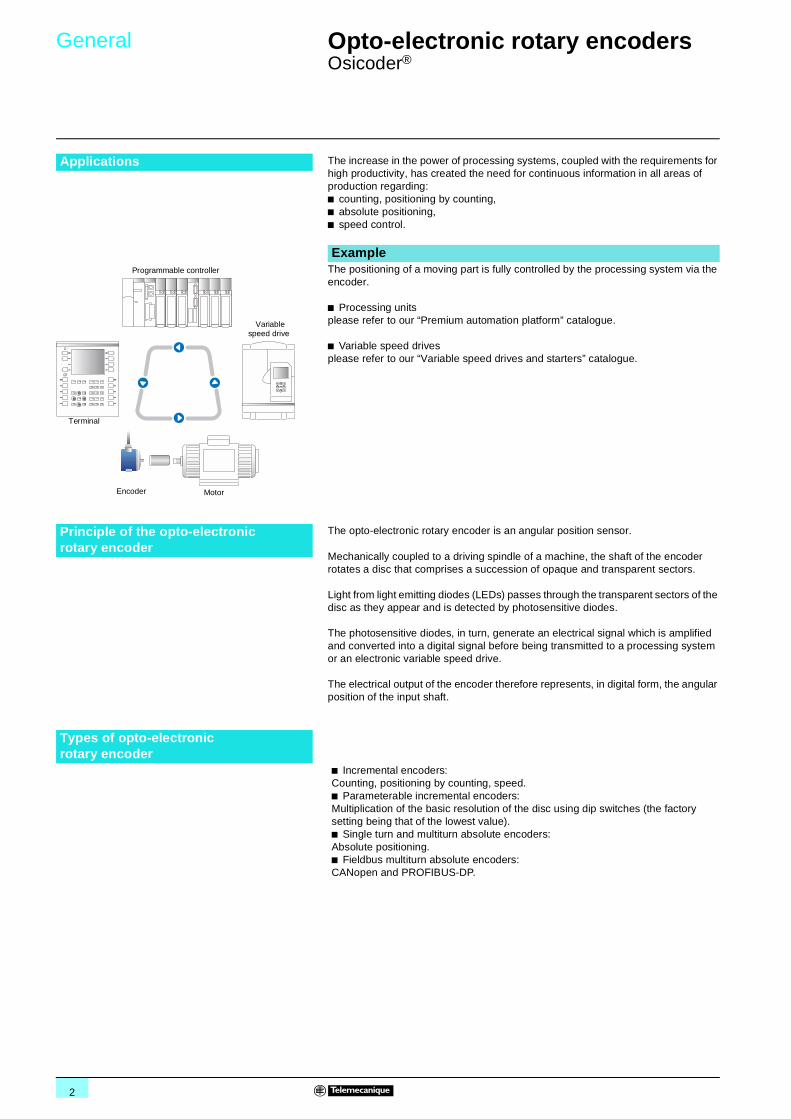
Applications The increase in the power of processing systems, coupled with the requirements for high productivity, has created the need for continuous information in all areas of production regarding:b counting, positioning by counting,b absolute positioning,b speed control.
ExampleThe positioning of a moving part is fully controlled by the processing system via the encoder.
b Processing unitsplease refer to our “Premium automation platform” catalogue.
b Variable speed drivesplease refer to our “Variable speed drives and starters” catalogue.
Principle of the opto-electronic rotary encoder
The opto-electronic rotary encoder is an angular position sensor.
Mechanically coupled to a driving spindle of a machine, the shaft of the encoder rotates a disc that comprises a succession of opaque and transparent sectors.
Light from light emitting diodes (LEDs) passes through the transparent sectors of the disc as they appear and is detected by photosensitive diodes.
The photosensitive diodes, in turn, generate an electrical signal which is amplified and converted into a digital signal before being transmitted to a processing system or an electronic variable speed drive.
The electrical output of the encoder therefore represents, in digital form, the angular position of the input shaft.
Types of opto-electronic rotary encoder
b Incremental encoders:Counting, positioning by counting, speed.b Parameterable incremental encoders:Multiplication of the basic resolution of the disc using dip switches (the factory setting being that of the lowest value).b Single turn and multiturn absolute encoders:Absolute positioning.b Fieldbus multiturn absolute encoders:CANopen and PROFIBUS-DP.
Variable speed drive
Programmable controller
MotorEncoder
Terminal
3
General (continued) 1 Opto-electronic rotary encoders 1
Osicoder®
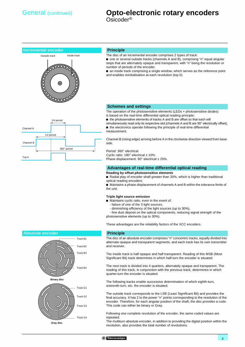
Incremental encoder PrincipleThe disc of an incremental encoder comprises 2 types of track:b one or several outside tracks (channels A and B), comprising “n” equal angular steps that are alternately opaque and transparent, with “n” being the resolution or number of periods of the encoder,b an inside track comprising a single window, which serves as the reference point and enables reinitialisation at each revolution (top 0).
Schemes and settingsThe operation of the photosensitive elements (LEDs + photosensitive diodes)is based on the real-time differential optical reading principle:b the photosensitive elements of tracks A and B are offset so that each will simultaneously read only its respective slot (channels A and B are 90° electrically offset),b the electronics operate following the principle of real-time differential measurement.
Channel B (rising edge) arriving before A in the clockwise direction viewed from base side.
Period: 360° electrical.Cyclic ratio: 180° electrical ± 10%. Phase displacement: 90° electrical ± 25%.
Advantages of real-time differential optical readingReading by offset photosensitive elementsb Radial play of encoder shaft greater than 30%, which is higher than traditional optical reading encoders.b Maintains a phase displacement of channels A and B within the tolerance limits of the unit.
Triple light source emissionb Maintains cyclic ratio, even in the event of:
- failure of one of the 3 light sources,- diminishing efficiency of the light sources (up to 30%), - fine dust deposit on the optical components, reducing signal strength of the
photosensitive elements (up to 30%).
These advantages are the reliability factors of the XCC encoders.
Absolute encoder PrincipleThe disc of an absolute encoder comprises “n” concentric tracks, equally divided into alternate opaque and transparent segments, and each track has its own transmitter and receiver.
The inside track is half opaque and half transparent. Reading of this MSB (Most Significant Bit) track determines in which half-turn the encoder is situated.
The next track is divided into 4 quarters, alternately opaque and transparent. The reading of this track, in conjunction with the previous track, determines in which quarter-turn the encoder is situated.
The following tracks enable successive determination of which eighth-turn, sixteenth-turn, etc. the encoder is situated.
The outside track corresponds to the LSB (Least Significant Bit) and provides the final accuracy. It has 2 to the power “n” points corresponding to the resolution of the encoder. Therefore, for each angular position of the shaft, the disc provides a code. This code can either be binary or Gray.
Following one complete revolution of the encoder, the same coded values are repeated.The multiturn absolute encoder, in addition to providing the digital position within the revolution, also provides the total number of revolutions.
Outside track Inside track
Channel A
Channel B
Top 0
360° period
1/2 period
1/4 period
Track B1
Track B2
Track B3
Track B4
Track G1
Track G2
Track G3
Track G4
Binary disc
Gray disc
4
General (continued) 1 Opto-electronic rotary encoders 1
Osicoder®
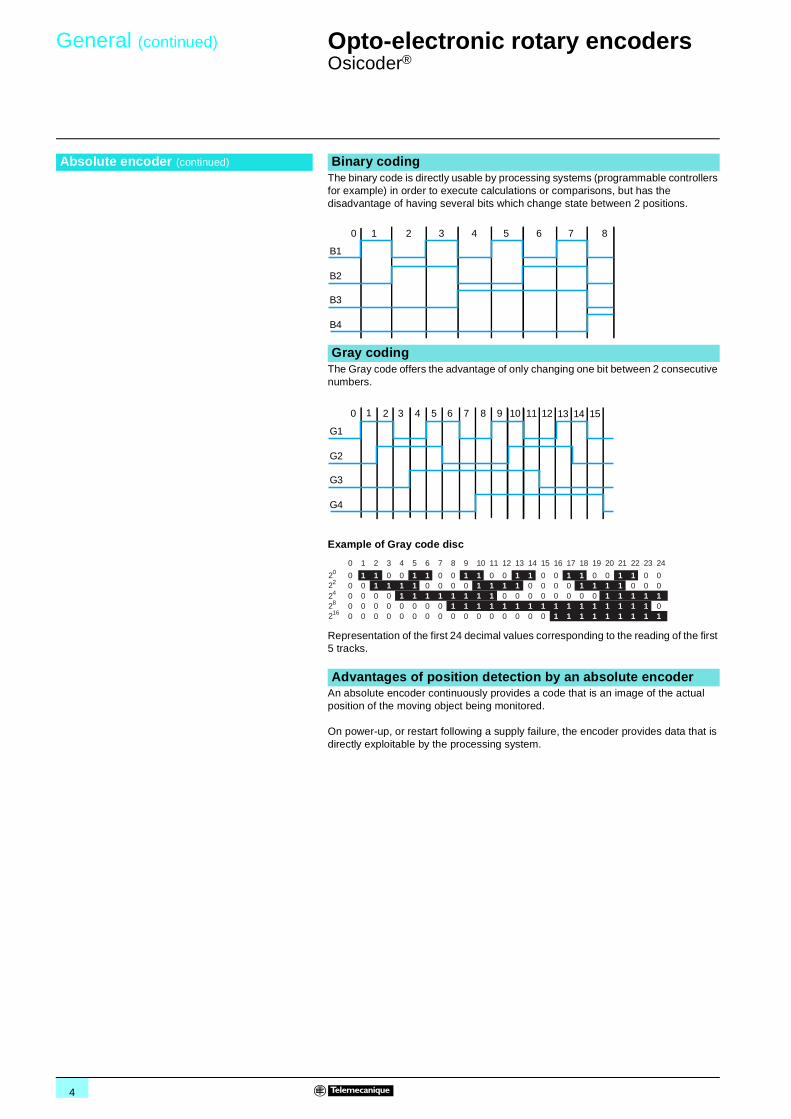
Absolute encoder (continued) Binary codingThe binary code is directly usable by processing systems (programmable controllers for example) in order to execute calculations or comparisons, but has the disadvantage of having several bits which change state between 2 positions.
Gray codingThe Gray code offers the advantage of only changing one bit between 2 consecutive numbers.
Example of Gray code disc
Representation of the first 24 decimal values corresponding to the reading of the first 5 tracks.
Advantages of position detection by an absolute encoderAn absolute encoder continuously provides a code that is an image of the actual position of the moving object being monitored.
On power-up, or restart following a supply failure, the encoder provides data that is directly exploitable by the processing system.
B1
0 1 2 3 4 5 6 7 8
B2
B3
B4
G1
0 1 2 3 4 5 6 7 8 9 10 11 12 13 14 15
G2
G3
G4
0 1 2 3 4 5 6 7 8 9 10 11 12 13 14 15 16 17 18 19 20 21 22 23 24
0 0 0 0 0 0 0 0 0 0 0 0 00 0 0 0 0 0 0 0 0 0 0 0 00 0 0 0 0 0 0 0 0 0 0 00 0 0 0 0 0 0 0 00 0 0 0 0 0 0 0 0 0 0 0 0 0 0 0
1 1 1 1 1 1 1 1 1 1 1 11 1 1 1 1 1 1 1 1 1 1 1
1 1 1 1 1 1 1 1 1 1 1 1 11 1 1 1 1 1 1 1 1 1 1 1 1 1 1 1
1 1 1 1 1 1 1 1 1
20
22
24
28
216
5
Selection of encoder type 1 Opto-electronic rotary encoders 1
Osicoder®
7 characteristics to be established 1 Functionb Incremental encoderProvides counting indication.
b Single turn absolute encoderProvides absolute position within each revolution.
b Multiturn absolute encoderProvides absolute position within each revolution and indicates total number of revolutions.
2 Diameter of housingb Incremental encodersØ 40, 58 and 90
b Single turn and multiturn absolute encodersØ 58 and 90
3 Diameter of shaftb Ø 6 mm to 30 mm, depending on model.b Reduction collarsFor Ø 58 and 90 mm encoders, with Ø 14, 15 and 30 mm through shaft, reduction collars are available to reduce the diameters: - from 14 to 6, 8, 10 and 12- from 15 to 6, 8, 10, 12 and 14- from 30 to 12, 16, 20 and 25.
4 Type of shaftb Solid shaftThe shaft of the encoder is mechanically linked to a drive shaft using a flexible coupling, which eliminates alignment inaccuracies.
b Through shaft/Hollow shaftThe encoder is mounted directly on the drive shaft. A flexible mounting kit prevents encoder rotation and compensates for alignment inaccuracies.
5 Connection methodb Pre-cabled with 2 m long shielded cable or M23/M12 connector.b Radial type connection.
6 Resolutionb Number of points per revolution.b Number of revolutions (for multiturn absolute encoders).b On Ø 58 parameterable incremental encoders, this resolution can be adjusted using dip switches (multiplication factor up to 16 times on 9 basic resolutions).
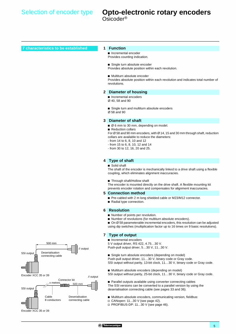
7 Type of outputb Incremental encoders5 V output driver, RS 422, 4.75…30 V.Push-pull output driver, 5…30 V, 11...30 V.
b Single turn absolute encoders (depending on model)Push-pull output driver, 11…30 V, binary code or Gray code.SSI output without parity, 13-bit clock, 11…30 V, binary code or Gray code.
b Multiturn absolute encoders (depending on model)SSI output without parity, 25-bit clock, 11…30 V, binary code or Gray code.
b Parallel outputs available using converter connecting cablesThe SSI versions can be converted to a parallel version by using the deserialisation connecting cable (see pages 33 and 36).
b Multiturn absolute encoders, communicating version, fieldbus:v CANopen: 11...30 V (see page 42).v PROFIBUS-DP: 11...30 V (see page 46).
500 mm
500 mm
SSI output
SSI output
// output
// outputEncoder XCC 35 or 39
Encoder XCC 35 or 39
Deserialisation connecting cable
Cable 8 conductors
Deserialisation connecting cable
Connector kitx metres

6
Precautions 1 Opto-electronic rotary encoders 1
Osicoder®
Installation precautions Type of cablesIn an environment subject to considerable electrical interference, it is recommended that cables with several twisted pairs, reinforced by general shielding, be used.
For the signals, it is recommended that standard 0.14 mm2/0.22 mm2 conductors be used.
For 5 V supply encoders.Due to line voltage drops, it is recommended that the 0 V and + V cables have the following minimum cross-sectional areas:b 0.14 mm2 if the encoder-supply distance is less than 30 m,b 0.22 mm2 if the encoder-supply distance is greater than 30 m.
CablingSeparate, by as much as possible, the connecting cables to encoders and power cables. Also, avoid parallel cable runs. Maintain a distance of at least 20 cm and, in the event of cables crossing, ensure that the crossovers are at right-angles.
When using cables with twisted pairs (shielded or non shielded) group signal cables in common pairs.
In environments subject to electrical interference, it is recommended to earth the encoder base using one of the fixing screws.
Connect the control inputs to a potential (absolute encoder).Connect all 0 V connections back to a star point, i.e. only one and same referential.Earth the shielding throughout 360° using tap-off braids. This is to be done at both ends of each cable. To earth the shielding use at least 4 mm2 cable. As much as possible, earth the 0 V of the supply to the encoders on the supply side.Maximum frequency of signals for SSI depending on distance:Indicative values that can vary depending on the cable characteristicsDistance (m) Frequency (kHz)
50 400
100 300
200 200
400 100
SupplyIt is imperative that regulated and smoothed power supplies, with a ripple factor on 24 V of 500 mV and on 5 V of 200 mV, are used that are specifically for the encoder. Telemecanique ABL7 range power supplies are available. Please refer to our “Power supplies, splitter boxes and interfaces” catalogue. For 5…30 V encoders, the supply via a transformer with a 24 V rms rectified and smoothed secondary is prohibited, since the d.c. voltage obtained is higher than the supply voltage limits of the encoder.Prior to powering-up for the first time, ensure that the rated supply voltage of the encoder is suitable for the supply.

7
Precautions 1 Opto-electronic rotary encoders 1
Osicoder®
Connection and powering-up precautions
Connection
The plugging-in or unplugging of a connector version encoder must only be done whilst the supply is disconnected.
Encoder supplied by central unit:b disconnect supply to central unit,b proceed with connection or disconnection,b re-establish supply to central unit.Encoder supplied by source external to central unit:b disconnect supply to central unit, then disconnect supply to encoder,b proceed with connection or disconnection,b re-establish supply to encoder, then re-establish supply to central unit.
Powering-upFor synchronisation reasons, the powering-up or switching-off of the encoder must coincide with that of its associated electronics.
8
Selection guide 1 Opto-electronic rotary encoders 1
Osicoder®
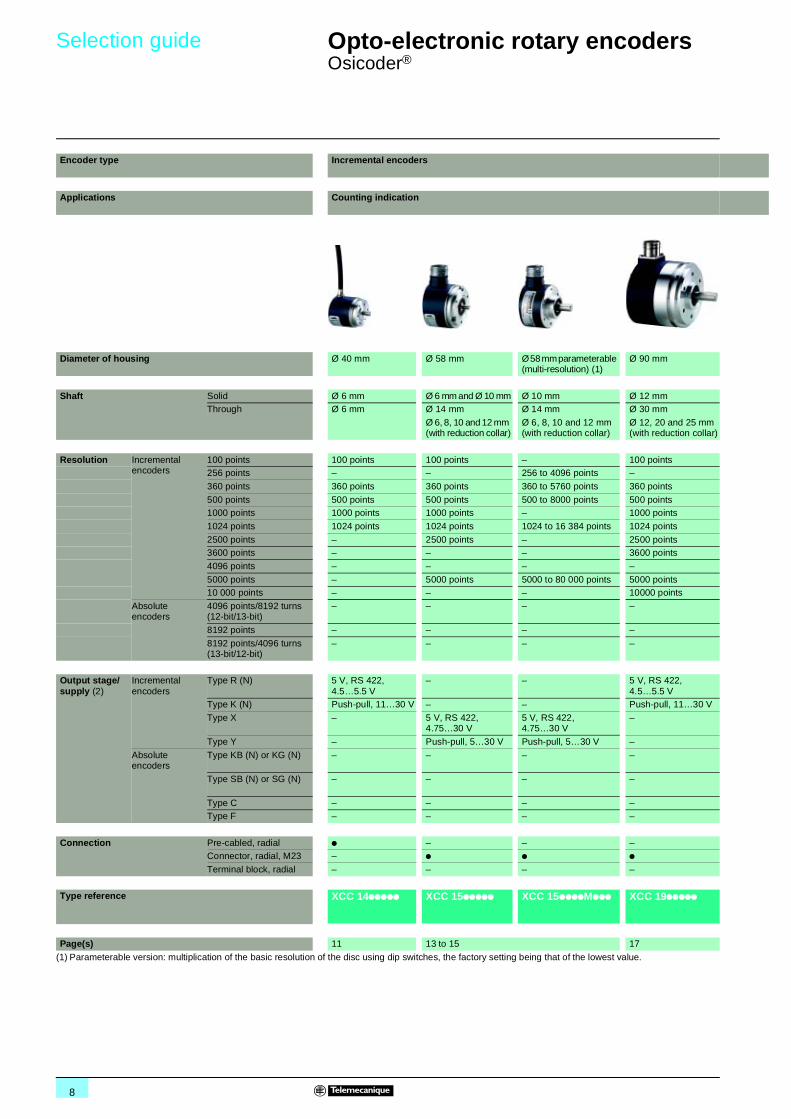
Encoder type Incremental encoders
Applications Counting indication
Diameter of housing Ø 40 mm Ø 58 mm Ø 58 mm parameterable (multi-resolution) (1)
Ø 90 mm
Shaft Solid Ø 6 mm Ø 6 mm and Ø 10 mm Ø 10 mm Ø 12 mmThrough Ø 6 mm Ø 14 mm Ø 14 mm Ø 30 mm
Ø 6, 8, 10 and 12 mm (with reduction collar)
Ø 6, 8, 10 and 12 mm (with reduction collar)
Ø 12, 20 and 25 mm (with reduction collar)
Resolution Incremental encoders
100 points 100 points 100 points – 100 points256 points – – 256 to 4096 points –
360 points 360 points 360 points 360 to 5760 points 360 points
500 points 500 points 500 points 500 to 8000 points 500 points1000 points 1000 points 1000 points – 1000 points
1024 points 1024 points 1024 points 1024 to 16 384 points 1024 points
2500 points – 2500 points – 2500 points3600 points – – – 3600 points
4096 points – – – –
5000 points – 5000 points 5000 to 80 000 points 5000 points10 000 points – – – 10000 points
Absolute encoders
4096 points/8192 turns (12-bit/13-bit)
– – – –
8192 points – – – –
8192 points/4096 turns (13-bit/12-bit)
– – – –
Output stage/ supply (2)
Incremental encoders
Type R (N) 5 V, RS 422, 4.5…5.5 V
– – 5 V, RS 422, 4.5…5.5 V
Type K (N) Push-pull, 11…30 V – – Push-pull, 11…30 V
Type X – 5 V, RS 422, 4.75…30 V
5 V, RS 422, 4.75…30 V
–
Type Y – Push-pull, 5…30 V Push-pull, 5…30 V –
Absolute encoders
Type KB (N) or KG (N) – – – –
Type SB (N) or SG (N) – – – –
Type C – – – –Type F – – – –
Connection Pre-cabled, radial p – – –Connector, radial, M23 – p p pTerminal block, radial – – – –
Type reference XCC 14ppppp XCC 15ppppp XCC 15ppppMppp XCC 19ppppp
Page(s) 11 13 to 15 17
(1) Parameterable version: multiplication of the basic resolution of the disc using dip switches, the factory setting being that of the lowest value.
9
1
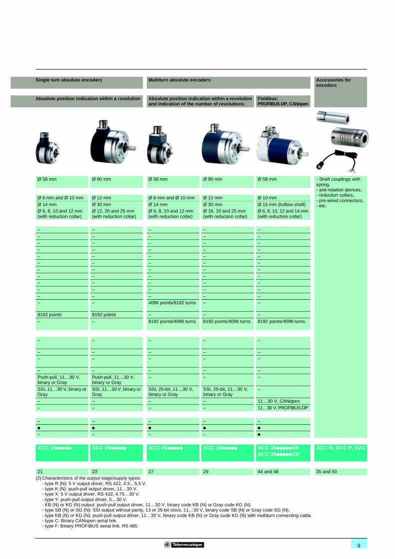
Single turn absolute encoders Multiturn absolute encoders Accessories for encoders
Absolute position indication within a revolution Absolute position indication within a revolution and indication of the number of revolutions
Fieldbus: PROFIBUS-DP, CANopen
Ø 58 mm Ø 90 mm Ø 58 mm Ø 90 mm Ø 58 mm - Shaft couplings with spring,- anti-rotation devices,- reduction collars,- pre-wired connectors, - etc.
Ø 6 mm and Ø 10 mm Ø 12 mm Ø 6 mm and Ø 10 mm Ø 12 mm Ø 10 mm
Ø 14 mm Ø 30 mm Ø 14 mm Ø 30 mm Ø 15 mm (hollow shaft)Ø 6, 8, 10 and 12 mm (with reduction collar)
Ø 12, 20 and 25 mm (with reduction collar)
Ø 6, 8, 10 and 12 mm (with reduction collar)
Ø 16, 20 and 25 mm (with reduction collar)
Ø 6, 8, 10, 12 and 14 mm (with reduction collar)
– – – – –
– – – – –– – – – –
– – – – –
– – – – –– – – – –
– – – – –
– – – – –– – – – –
– – – – –
– – – – –– – 4096 points/8192 turns – –
8192 points 8192 points – – –
– – 8192 points/4096 turns 8192 points/4096 turns 8192 points/4096 turns
– – – – –
– – – – –– – – – –
– – – – –
Push-pull, 11…30 V, binary or Gray
Push-pull, 11…30 V, binary or Gray
– – –
SSI, 11…30 V, binary or Gray
SSI, 11…30 V, binary or Gray
SSI, 25-bit, 11…30 V, binary or Gray
SSI, 25-bit, 11…30 V, binary or Gray
–
– – – – 11…30 V, CANopen
– – – – 11…30 V, PROFIBUS-DP
– – – – –
p p p p p– – – – p
XCC 25ppppp XCC 29ppppp XCC 35ppppp XCC 39ppppp XCC 35pppppFBXCC 35pppppCB
XCC R, XCC P, XZC
21 23 27 29 44 and 48 35 and 50(2) Characteristics of the output stage/supply types:
- type R (N): 5 V output driver, RS 422, 4.5…5.5 V.- type K (N): push-pull output driver, 11…30 V.- type X: 5 V output driver, RS 422, 4.75…30 V.- type Y: push-pull output driver, 5…30 V.- KB (N) or KG (N) output: push-pull output driver, 11…30 V, binary code KB (N) or Gray code KG (N).- type SB (N) or SG (N): SSI output without parity, 13 or 25-bit clock, 11…30 V, binary code SB (N) or Gray code SG (N).- type KB (N) or KG (N): push-pull output driver, 11…30 V, binary code KB (N) or Gray code KG (N) with multiturn connecting cable.- type C: Binary CANopen serial link.- type F: Binary PROFIBUS serial link, RS 485.
10
Characteristics, schemes 1
Incremental encoders 1
Osicoder®
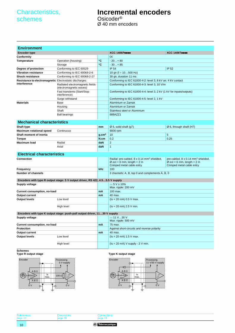
Ø 40 mm encoders
EnvironmentEncoder type XCC 1406Ppppp XCC 1406Tpppp
Conformity eTemperature Operation (housing) °C - 20…+ 80
Storage °C - 30…+ 85
Degree of protection Conforming to IEC 60529 IP 54 IP 52
Vibration resistance Conforming to IEC 60068-2-6 10 gn (f = 10…500 Hz)Shock resistance Conforming to IEC 60068-2-27 30 gn, duration 11 ms
Resistance to electromagnetic interference
Electrostatic discharges Conforming to IEC 61000-4-2: level 3, 8 kV air; 4 kV contact
Radiated electromagnetic fields (electromagnetic waves)
Conforming to IEC 61000-4-3: level 3, 10 V/m
Fast transients (Start/Stop interference)
Conforming to IEC 61000-4-4: level 3, 2 kV (1 kV for inputs/outputs)
Surge withstand Conforming to IEC 61000-4-5: level 2, 1 kVMaterials Base Aluminium or Zamak
Housing Aluminium or Zamak
Shaft Stainless steel or AluminiumBall bearings 688AZZ1
Mechanical characteristicsShaft type mm Ø 6, solid shaft (g7) Ø 6, through shaft (H7)
Maximum rotational speed Continuous 9000 rpm
Shaft moment of inertia g.cm2 10 5Torque N.cm 0.2 0.25
Maximum load Radial daN 2
Axial daN 1
Electrical characteristicsConnection Radial: pre-cabled, 8 x 0.14 mm2 shielded,
Ø ext = 6 mm, length = 2 mCrimped metal cable entry
pre-cabled, 8 x 0.14 mm2 shielded, Ø ext = 6 mm, length = 2 mCrimped metal cable entry
Frequency kHz 100
Number of channels 3 channels: A, B, top 0 and complements
Encoders with type R output stage: 5 V output driver, RS 422, 4.5…5.5 V supplySupply voltage c 5 V ± 10%
Max. ripple: 200 mV
Current consumption, no-load mA 100 max.Output current mA 40 max.
Output levels Low level (Is = 20 mA) 0.5 V max.
High level (Is = 20 mA) 2.5 V min.
Encoders with type K output stage: push-pull output driver, 11…30 V supplySupply voltage c 11 V…30 V
Max. ripple: 500 mV
Current consumption, no-load mA 75 max.Protection Against short-circuits and reverse polarity
Output current mA 40 max.
Output levels Low level (Is = 20 mA) 1.5 V max.
High level (Is = 20 mA) V supply - 3 V min.
SchemesType R output stage Type K output stage
A, B, 0
0 V
100 RS422
0 V
A B 0
A B 0
Encoder Processing5 V supply
Ismax.
0 V0 V
A B 0
A B 0
Push-Pull
Encoder Processing11 V/30 V supply
Ismax.
References:page 11
Dimensions:page 18
Connections:page 19
11
References 1 Incremental encoders 1
Osicoder®
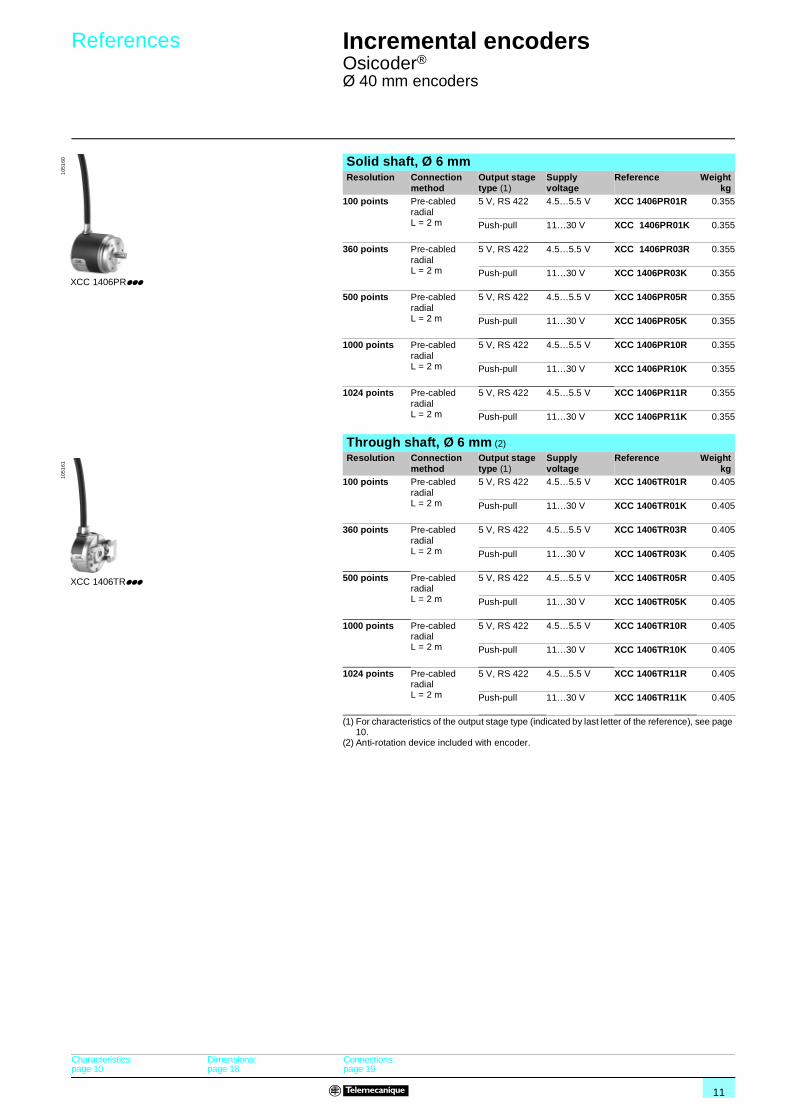
Ø 40 mm encoders
Solid shaft, Ø 6 mmResolution Connection
methodOutput stage type (1)
Supply voltage
Reference Weightkg
100 points Pre-cabled radial L = 2 m
5 V, RS 422 4.5…5.5 V XCC 1406PR01R 0.355
Push-pull 11…30 V XCC 1406PR01K 0.355
360 points Pre-cabled radial L = 2 m
5 V, RS 422 4.5…5.5 V XCC 1406PR03R 0.355
Push-pull 11…30 V XCC 1406PR03K 0.355
500 points Pre-cabled radial L = 2 m
5 V, RS 422 4.5…5.5 V XCC 1406PR05R 0.355
Push-pull 11…30 V XCC 1406PR05K 0.355
1000 points Pre-cabled radial L = 2 m
5 V, RS 422 4.5…5.5 V XCC 1406PR10R 0.355
Push-pull 11…30 V XCC 1406PR10K 0.355
1024 points Pre-cabled radial L = 2 m
5 V, RS 422 4.5…5.5 V XCC 1406PR11R 0.355
Push-pull 11…30 V XCC 1406PR11K 0.355
Through shaft, Ø 6 mm (2) Resolution Connection
methodOutput stage type (1)
Supply voltage
Reference Weightkg
100 points Pre-cabled radial L = 2 m
5 V, RS 422 4.5…5.5 V XCC 1406TR01R 0.405
Push-pull 11…30 V XCC 1406TR01K 0.405
360 points Pre-cabled radial L = 2 m
5 V, RS 422 4.5…5.5 V XCC 1406TR03R 0.405
Push-pull 11…30 V XCC 1406TR03K 0.405
500 points Pre-cabled radial L = 2 m
5 V, RS 422 4.5…5.5 V XCC 1406TR05R 0.405
Push-pull 11…30 V XCC 1406TR05K 0.405
1000 points Pre-cabled radial L = 2 m
5 V, RS 422 4.5…5.5 V XCC 1406TR10R 0.405
Push-pull 11…30 V XCC 1406TR10K 0.405
1024 points Pre-cabled radial L = 2 m
5 V, RS 422 4.5…5.5 V XCC 1406TR11R 0.405
Push-pull 11…30 V XCC 1406TR11K 0.405
(1) For characteristics of the output stage type (indicated by last letter of the reference), see page 10.
(2) Anti-rotation device included with encoder.
XCC 1406PRppp
105
160
1051
61
XCC 1406TRppp
Characteristics:page 10
Dimensions:page 18
Connections:page 19
12
Characteristics, schemes 1
Incremental encoders 1
Osicoder®
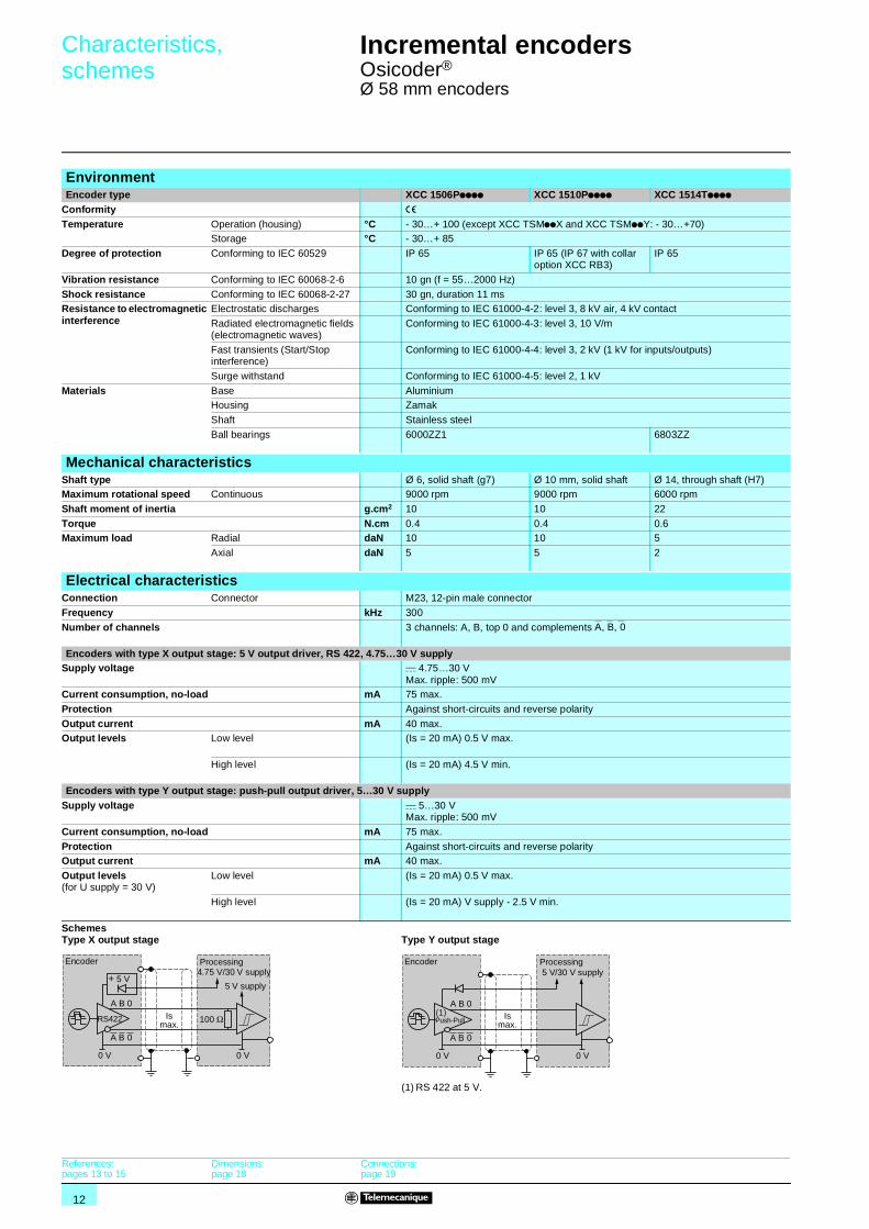
Ø 58 mm encoders
EnvironmentEncoder type XCC 1506Ppppp XCC 1510Ppppp XCC 1514Tpppp
Conformity eTemperature Operation (housing) °C - 30…+ 100 (except XCC TSMppX and XCC TSMppY: - 30…+70)
Storage °C - 30…+ 85
Degree of protection Conforming to IEC 60529 IP 65 IP 65 (IP 67 with collar option XCC RB3)
IP 65
Vibration resistance Conforming to IEC 60068-2-6 10 gn (f = 55…2000 Hz)
Shock resistance Conforming to IEC 60068-2-27 30 gn, duration 11 msResistance to electromagnetic interference
Electrostatic discharges Conforming to IEC 61000-4-2: level 3, 8 kV air, 4 kV contact
Radiated electromagnetic fields (electromagnetic waves)
Conforming to IEC 61000-4-3: level 3, 10 V/m
Fast transients (Start/Stop interference)
Conforming to IEC 61000-4-4: level 3, 2 kV (1 kV for inputs/outputs)
Surge withstand Conforming to IEC 61000-4-5: level 2, 1 kV
Materials Base AluminiumHousing Zamak
Shaft Stainless steel
Ball bearings 6000ZZ1 6803ZZ
Mechanical characteristicsShaft type Ø 6, solid shaft (g7) Ø 10 mm, solid shaft Ø 14, through shaft (H7)Maximum rotational speed Continuous 9000 rpm 9000 rpm 6000 rpm
Shaft moment of inertia g.cm2 10 10 22
Torque N.cm 0.4 0.4 0.6Maximum load Radial daN 10 10 5
Axial daN 5 5 2
Electrical characteristicsConnection Connector M23, 12-pin male connector
Frequency kHz 300
Number of channels 3 channels: A, B, top 0 and complements
Encoders with type X output stage: 5 V output driver, RS 422, 4.75…30 V supplySupply voltage c 4.75…30 V
Max. ripple: 500 mVCurrent consumption, no-load mA 75 max.
Protection Against short-circuits and reverse polarity
Output current mA 40 max.Output levels Low level (Is = 20 mA) 0.5 V max.
High level (Is = 20 mA) 4.5 V min.
Encoders with type Y output stage: push-pull output driver, 5…30 V supplySupply voltage c 5…30 V
Max. ripple: 500 mV
Current consumption, no-load mA 75 max.
Protection Against short-circuits and reverse polarityOutput current mA 40 max.
Output levels(for U supply = 30 V)
Low level (Is = 20 mA) 0.5 V max.
High level (Is = 20 mA) V supply - 2.5 V min.
SchemesType X output stage Type Y output stage
(1) RS 422 at 5 V.
A, B, 0
0 V
100 RS422
+ 5 V
0 V
A B 0
A B 0
Encoder Processing4.75 V/30 V supply
Ismax.
5 V supply
0 V0 V
A B 0
A B 0
Push-Pull(1)
Encoder Processing5 V/30 V supply
Ismax.
References:pages 13 to 15
Dimensions:page 18
Connections:page 19
13
References 1 Incremental encoders 1
Osicoder®
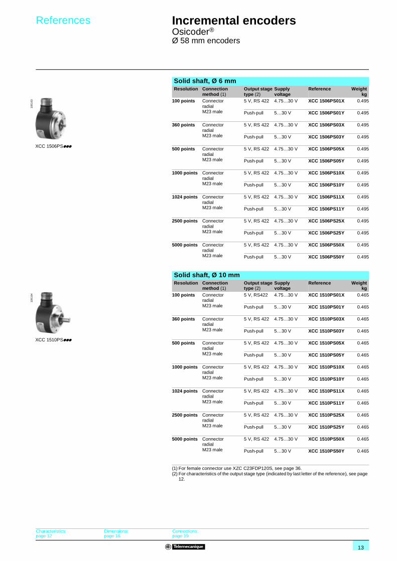
Ø 58 mm encoders
Solid shaft, Ø 6 mmResolution Connection
method (1)Output stage type (2)
Supply voltage
Reference Weightkg
100 points Connector radial M23 male
5 V, RS 422 4.75…30 V XCC 1506PS01X 0.495
Push-pull 5…30 V XCC 1506PS01Y 0.495
360 points Connector radial M23 male
5 V, RS 422 4.75…30 V XCC 1506PS03X 0.495
Push-pull 5…30 V XCC 1506PS03Y 0.495
500 points Connector radial M23 male
5 V, RS 422 4.75…30 V XCC 1506PS05X 0.495
Push-pull 5…30 V XCC 1506PS05Y 0.495
1000 points Connector radial M23 male
5 V, RS 422 4.75…30 V XCC 1506PS10X 0.495
Push-pull 5…30 V XCC 1506PS10Y 0.495
1024 points Connector radial M23 male
5 V, RS 422 4.75…30 V XCC 1506PS11X 0.495
Push-pull 5…30 V XCC 1506PS11Y 0.495
2500 points Connector radial M23 male
5 V, RS 422 4.75…30 V XCC 1506PS25X 0.495
Push-pull 5…30 V XCC 1506PS25Y 0.495
5000 points Connector radial M23 male
5 V, RS 422 4.75…30 V XCC 1506PS50X 0.495
Push-pull 5…30 V XCC 1506PS50Y 0.495
Solid shaft, Ø 10 mmResolution Connection
method (1)Output stage type (2)
Supply voltage
Reference Weightkg
100 points Connector radial M23 male
5 V, RS422 4.75…30 V XCC 1510PS01X 0.465
Push-pull 5…30 V XCC 1510PS01Y 0.465
360 points Connector radial M23 male
5 V, RS 422 4.75…30 V XCC 1510PS03X 0.465
Push-pull 5…30 V XCC 1510PS03Y 0.465
500 points Connector radial M23 male
5 V, RS 422 4.75…30 V XCC 1510PS05X 0.465
Push-pull 5…30 V XCC 1510PS05Y 0.465
1000 points Connector radial M23 male
5 V, RS 422 4.75…30 V XCC 1510PS10X 0.465
Push-pull 5…30 V XCC 1510PS10Y 0.465
1024 points Connector radial M23 male
5 V, RS 422 4.75…30 V XCC 1510PS11X 0.465
Push-pull 5…30 V XCC 1510PS11Y 0.465
2500 points Connector radial M23 male
5 V, RS 422 4.75…30 V XCC 1510PS25X 0.465
Push-pull 5…30 V XCC 1510PS25Y 0.465
5000 points Connector radial M23 male
5 V, RS 422 4.75…30 V XCC 1510PS50X 0.465
Push-pull 5…30 V XCC 1510PS50Y 0.465
(1) For female connector use XZC C23FDP120S, see page 36.(2) For characteristics of the output stage type (indicated by last letter of the reference), see page
12.
XCC 1506PSppp
105
163
XCC 1510PSppp
105
164
Characteristics:page 12
Dimensions:page 18
Connections:page 19
14
References (continued) 1 Incremental encoders 1
Osicoder®
Ø 58 mm encoders
Through shaft, Ø 14 mm (1)Resolution Connection
method (2)Output stage type (3)
Supply voltage
Reference Weightkg
100 points Connector radial M23 male
5 V, RS 422 4.75…30 V XCC 1514TS01X 0.435
Push-pull 5…30 V XCC 1514TS01Y 0.435
360 points Connector radial M23 male
5 V, RS 422 4.75…30 V XCC 1514TS03X 0.435
Push-pull 5…30 V XCC 1514TS03Y 0.435
500 points Connector radial M23 male
5 V, RS 422 4.75…30 V XCC 1514TS05X 0.435
Push-pull 5…30 V XCC 1514TS05Y 0.435
1000 points Connector radial M23 male
5 V, RS 422 4.75…30 V XCC 1514TS10X 0.435
Push-pull 5…30 V XCC 1514TS10Y 0.435
1024 points Connector radial M23 male
5 V, RS 422 4.75…30 V XCC 1514TS11X 0.435
Push-pull 5…30 V XCC 1514TS11Y 0.435
2500 points Connector radial M23 male
5 V, RS 422 4.75…30 V XCC 1514TS25X 0.435
Push-pull 5…30 V XCC 1514TS25Y 0.435
5000 points Connector radial M23 male
5 V, RS 422 4.75…30 V XCC 1514TS50X 0.435
Push-pull 5…30 V XCC 1514TS50Y 0.435
Through shaft, Ø 6, 8, 10 and 12 mm (1)Encoder type Diameter
mm
Reduction collar to be ordered (see page 37)
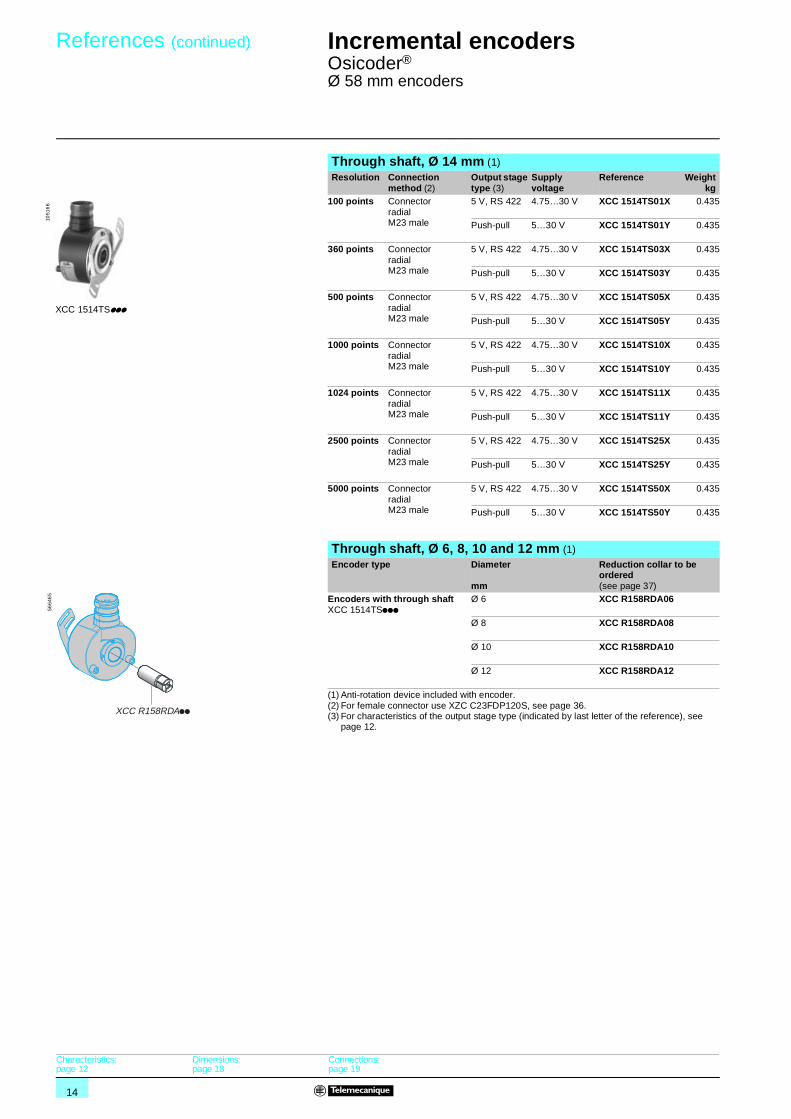
Encoders with through shaft XCC 1514TSppp
Ø 6 XCC R158RDA06
Ø 8 XCC R158RDA08
Ø 10 XCC R158RDA10
Ø 12 XCC R158RDA12
(1) Anti-rotation device included with encoder.(2) For female connector use XZC C23FDP120S, see page 36.(3) For characteristics of the output stage type (indicated by last letter of the reference), see
page 12.
XCC 1514TSppp
1051
66
XCC R158RDA
5664
65
Characteristics:page 12
Dimensions:page 18
Connections:page 19
15
References (continued) 1 Incremental encoders 1
Osicoder®
Ø 58 mm encodersParameterable versions (1)
Parameterable with solid shaft, Ø 10 mmResolution Connection
method (2)Output stage type (3)
Supply voltage
Reference Weightkg
256…4096 points
Connector radial M23 male
5 V, RS 422 4.75…30 V XCC 1510PSM02X 0.465
Push-pull 5…30 V XCC 1510PSM02Y 0.465
360…5760 points
Connector radial M23 male
5 V, RS 422 4.75…30 V XCC 1510PSM03X 0.465
Push-pull 5…30 V XCC 1510PSM03Y 0.465
500…8000 points
Connector radial M23 male
5 V, RS 422 4.75…30 V XCC 1510PSM05X 0.465
Push-pull 5…30 V XCC 1510PSM05Y 0.465
1024…16 384 points
Connector radial M23 male
5 V, RS 422 4.75…30 V XCC 1510PSM11X 0.465
Push-pull 5…30 V XCC 1510PSM11Y 0.465
5000…80 000 points
Connector radial M23 male
5 V, RS 422 4.75…30 V XCC 1510PSM50X 0.465
Push-pull 5…30 V XCC 1510PSM50Y 0.465
Parameterable with through shaft, Ø 14 mm (4)Resolution Connection
method (2)Output stage type (3)
Supply voltage
Reference Weightkg
256…4096 points
Connector radial M23 male
5 V, RS 422 4.75…30 V XCC 1514TSM02X 0.435
Push-pull 5…30 V XCC 1514TSM02Y 0.435
360…5760 points
Connector radial M23 male
5 V, RS 422 4.75…30 V XCC 1514TSM03X 0.435
Push-pull 5…30 V XCC 1514TSM03Y 0.435
500…8000 points
Connector radial M23 male
5 V, RS 422 4.75…30 V XCC 1514TSM05X 0.435
Push-pull 5…30 V XCC 1514TSM05Y 0.435
1024…16 384 points
Connector radial M23 male
5 V, RS 422 4.75…30 V XCC 1514TSM11X 0.435
Push-pull 5…30 V XCC 1514TSM11Y 0.435
5000…80 000 points
Connector radial M23 male
5 V, RS 422 4.75…30 V XCC 1514TSM50X 0.435
Push-pull 5…30 V XCC 1514TSM50Y 0.435
Parameterable with through shaft, Ø 6, 8, 10 and 12 mm (4)Encoder type Diameter
mmReduction collar to be ordered (see page 37)
Encoders with through shaft XCC 1514TSMppp
Ø 6 XCC R158RDA06
Ø 8 XCC R158RDA08
Ø 10 XCC R158RDA10
Ø 12 XCC R158RDA12
(1) Parameter configuration: refer to table indicating position of dip switches on page 19.(2) For female connector use XZC C23FDP120S, see page 36.(3) For characteristics of the output stage type (indicated by last letter of the reference), see
page 12.(4) Anti-rotation device included with encoder.
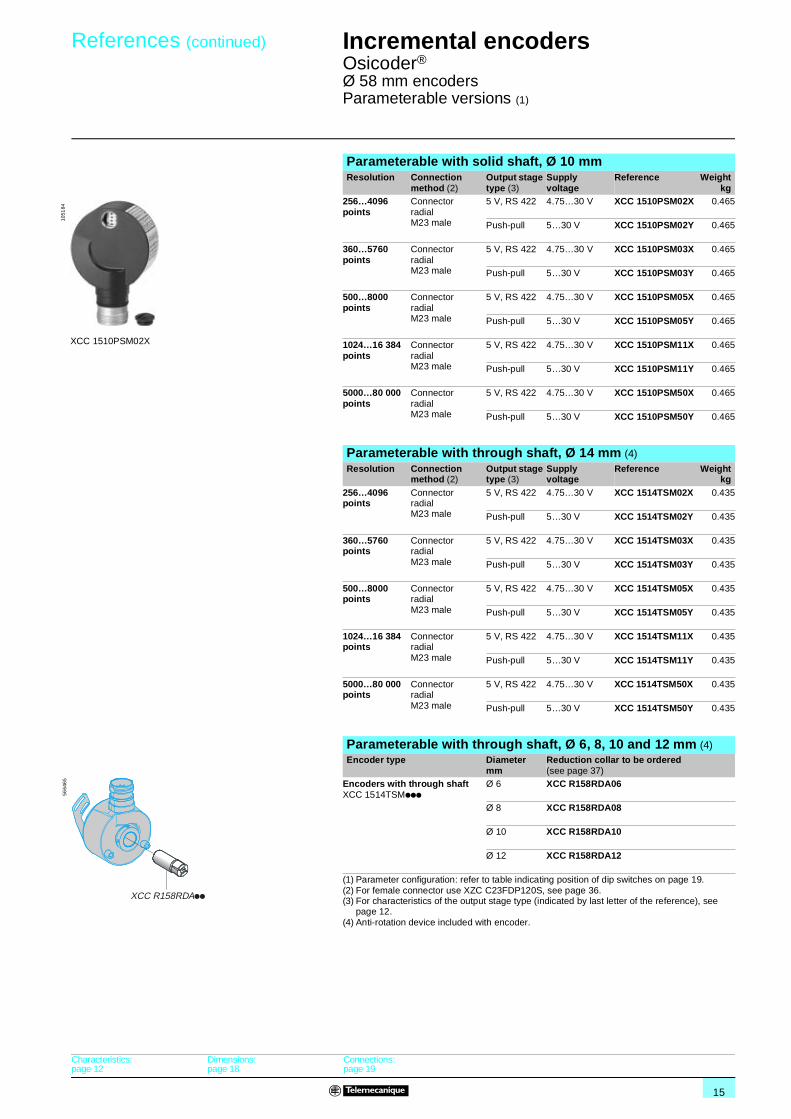
XCC 1510PSM02X
1051
84
XCC R158RDA
5664
65
Characteristics:page 12
Dimensions:page 18
Connections:page 19
16
Characteristics, schemes 1
Incremental encoders 1
Osicoder®
Ø 90 mm encoders
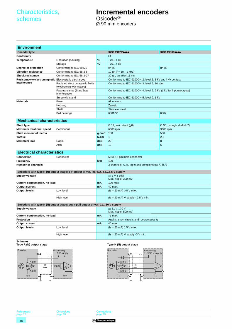
EnvironmentEncoder type XCC 1912Ppppp XCC 1930Tpppp
Conformity eTemperature Operation (housing) °C - 20…+ 80
Storage °C - 30…+ 85
Degree of protection Conforming to IEC 60529 IP 66 IP 65
Vibration resistance Conforming to IEC 68-2-6 10 gn (f = 10…1 kHz)Shock resistance Conforming to IEC 68-2-27 30 gn, duration 11 ms
Resistance to electromagnetic interference
Electrostatic discharges Conforming to IEC 61000-4-2: level 3, 8 kV air; 4 kV contact
Radiated electromagnetic fields (electromagnetic waves)
Conforming to IEC 61000-4-3: level 3, 10 V/m
Fast transients (Start/Stop interference)
Conforming to IEC 61000-4-4: level 3, 2 kV (1 kV for inputs/outputs)
Surge withstand Conforming to IEC 61000-4-5: level 2, 1 kVMaterials Base Aluminium
Housing Zamak
Shaft Stainless steelBall bearings 6001ZZ 6807
Mechanical characteristicsShaft type Ø 12, solid shaft (g6) Ø 30, through shaft (H7)
Maximum rotational speed Continuous 6000 rpm 3600 rpm
Shaft moment of inertia g.cm2 150 500Torque N.cm 1 2.5
Maximum load Radial daN 20 8
Axial daN 10 5
Electrical characteristicsConnection Connector M23, 12-pin male connector
Frequency kHz 100Number of channels 3 channels: A, B, top 0 and complements
Encoders with type R (N) output stage: 5 V output driver, RS 422, 4.5…5.5 V supplySupply voltage c 5 V ± 10%
Max. ripple: 200 mV
Current consumption, no-load mA 100 max.
Output current mA 40 max.Output levels Low level (Is = 20 mA) 0.5 V max.
High level (Is = 20 mA) V supply - 2.5 V min.
Encoders with type K (N) output stage: push-pull output driver, 11…30 V supplySupply voltage c 11 V…30 V
Max. ripple: 500 mV
Current consumption, no-load mA 75 max.
Protection Against short-circuits and reverse polarityOutput current mA 40 max.
Output levels Low level (Is = 20 mA) 1.5 V max.
High level (Is = 20 mA) V supply -3 V min.
SchemesType R (N) output stage Type K (N) output stage
A, B, 0
0 V
100 RS422
0 V
A B 0
A B 0
Encoder Processing5 V supply
Ismax.
0 V0 V
A B 0
A B 0
Push-Pull
Encoder Processing11 V/30 V supply
Ismax.
References:page 17
Dimensions:page 18
Connections:page 19
17
References 1 Incremental encoders 1
Osicoder®
Ø 90 mm encoders
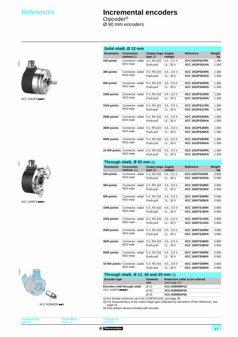
Solid shaft, Ø 12 mmResolution Connection
method (1)Output stage type (2)
Supply voltage
Reference Weightkg
100 points Connector, radial M23 male
5 V, RS 422 4.5…5.5 V XCC 1912PS01RN 1.360
Push-pull 11…30 V XCC 1912PS01KN 1.360
360 points Connector, radial M23 male
5 V, RS 422 4.5…5.5 V XCC 1912PS03RN 1.360
Push-pull 11…30 V XCC 1912PS03KN 1.360
500 points Connector, radial M23 male
5 V, RS 422 4.5…5.5 V XCC 1912PS05RN 1.360Push-pull 11…30 V XCC 1912PS05KN 1.360
1000 points Connector, radial M23 male
5 V, RS 422 4.5…5.5 V XCC 1912PS10RN 1.360
Push-pull 11…30 V XCC 1912PS10KN 1.360
1024 points Connector, radial M23 male
5 V, RS 422 4.5…5.5 V XCC 1912PS11RN 1.360
Push-pull 11…30 V XCC 1912PS11KN 1.360
2500 points Connector, radial M23 male
5 V, RS 422 4.5…5.5 V XCC 1912PS25RN 1.360Push-pull 11…30 V XCC 1912PS25KN 1.360
3600 points Connector, radial M23 male
5 V, RS 422 4.5…5.5 V XCC 1912PS36RN 1.360
Push-pull 11…30 V XCC 1912PS36KN 1.360
5000 points Connector, radial M23 male
5 V, RS 422 4.5…5.5 V XCC 1912PS50RN 1.360
Push-pull 11…30 V XCC 1912PS50KN 1.360
10 000 points Connector, radial M23 male
5 V, RS 422 4.5…5.5 V XCC 1912PS00RN 1.360Push-pull 11…30 V XCC 1912PS00KN 1.360
Through shaft, Ø 30 mm (3)Resolution Connection
method (1)Output stage type (2)
Supply voltage
Reference Weightkg
100 points Connector, radial M23 male
5 V, RS 422 4.5…5.5 V XCC 1930TS01RN 0.960Push-pull 11…30 V XCC 1930TS01KN 0.960
360 points Connector, radial M23 male
5 V, RS 422 4.5…5.5 V XCC 1930TS03RN 0.960
Push-pull 11…30 V XCC 1930TS03KN 0.960
500 points Connector, radial M23 male
5 V, RS 422 4.5…5.5 V XCC 1930TS05RN 0.960
Push-pull 11…30 V XCC 1930TS05KN 0.960
1000 points Connector, radial M23 male
5 V, RS 422 4.5…5.5 V XCC 1930TS10RN 0.960Push-pull 11…30 V XCC 1930TS10KN 0.960
1024 points Connector, radial M23 male
5 V, RS 422 4.5…5.5 V XCC 1930TS11RN 0.960
Push-pull 11…30 V XCC 1930TS11KN 0.960
2500 points Connector, radial M23 male
5 V, RS 422 4.5…5.5 V XCC 1930TS25RN 0.960
Push-pull 11…30 V XCC 1930TS25KN 0.960
3600 points Connector, radial M23 male
5 V, RS 422 4.5…5.5 V XCC 1930TS36RN 0.960Push-pull 11…30 V XCC 1930TS36KN 0.960
5000 points Connector, radial M23 male
5 V, RS 422 4.5…5.5 V XCC 1930TS50RN 0.960
Push-pull 11…30 V XCC 1930TS50KN 0.960
10 000 points Connector, radial M23 male
5 V, RS 422 4.5…5.5 V XCC 1930TS00RN 0.960
Push-pull 11…30 V XCC 1930TS00KN 0.960
Through shaft, Ø 12, 20 and 25 mm (3)Encoder type Diameter
mmReduction collar to be ordered (see page 37)
Encoders with through shaft XCC 1930TSppppN
Ø 12 XCC R290RDP12 Ø 20 XCC R290RDP20Ø 25 XCC R290RDP25
(1) For female connector use XZC C23FDP120S, see page 36.(2) For characteristics of the output stage type (indicated by last letters of the reference), see
page 16.(3) Anti-rotation device included with encoder.
XCC 1912PSpppN
105
168
XCC 1930TSpppN
105
171
523
200
XCC R290RDPppN
Characteristics:page 16
Dimensions:page 18
Connections:page 19
18
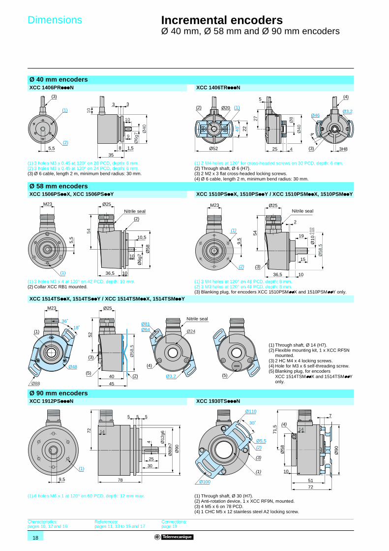
Dimensions 1 Incremental encoders 1
Ø 40 mm, Ø 58 mm and Ø 90 mm encoders
Ø 40 mm encodersXCC 1406PRpppN XCC 1406TRpppN
(1) 3 holes M3 x 0.45 at 120° on 28 PCD, depth: 6 mm.(2) 3 holes M3 x 0.45 at 120° on 24 PCD, depth: 6 mm.(3) Ø 6 cable, length 2 m, minimum bend radius: 30 mm.
(1) 2 M4 holes at 120° for cross-headed screws on 30 PCD, depth: 6 mm.(2) Through shaft, Ø 6 (H7).(3) 2 M2 x 3 flat cross-headed locking screws.(4) Ø 6 cable, length 2 m, minimum bend radius: 30 mm.
Ø 58 mm encodersXCC 1506PSppX, XCC 1506PSppY XCC 1510PSppX, 1510PSppY / XCC 1510PSMppX, 1510PSMppY
(1) 3 holes M3 x 4 at 120° on 42 PCD, depth: 10 mm.(2) Collar XCC RB1 mounted.
(1) 3 M4 holes at 120° on 48 PCD, depth: 8 mm.(2) 3 M3 holes at 120° on 48 PCD, depth: 8 mm.(3) Blanking plug, for encoders XCC 1510PSMppX and 1510PSMppY only.
XCC 1514TSppX, 1514TSppY / XCC 1514TSMppX, 1514TSMppY
(1) Through shaft, Ø 14 (H7).(2) Flexible mounting kit, 1 x XCC RF5N
mounted.(3) 2 HC M4 x 4 locking screws.(4) Hole for M3 x 6 self-threading screw.(5) Blanking plug, for encoders
XCC 1514TSMppX and 1514TSMppY only.
Ø 90 mm encodersXCC 1912PSpppN XCC 1930TSpppN
(1) 6 holes M6 x 1 at 120° on 60 PCD, depth: 12 mm max. (1) Through shaft, Ø 30 (H7).(2) Anti-rotation device, 1 x XCC RF9N, mounted.(3) 4 M5 x 6 on 78 PCD.(4) 1 CHC M5 x 12 stainless steel A2 locking screw.
9
5,5
Ø6g
7
10
Ø40
35
10
(2)
(3)
(1)
8 1,5
3 3
3H8
Ø46
Ø40
Ø8
40˚
22
(4)
Ø3,2(1)Ø20
27
25 4Ø52
(2)
(3)
4
5
36,5 10
Ø25M23
10
10,5
Ø6g
7
54
Ø58
5,5
(1)
(2)
Nitrile sealM23
9,5
(2)
(1)
(3)
54
Ø58
,5
Ø25
10
19
2
15
36,5
Ø10
-0,0
10-0
,025
Nitrile seal
Ø81Ø64
52
Ø58
,5
Ø88
Ø24
Ø25M23
40
45
Ø3,2
18˚36˚
(2) (5)
(3)
(4)
(1)
Ø48(5)
Nitrile seal
72
5
4
5
25
30
78
Ø12
g6
Ø80
h7
Ø90
5
(1)
9,5
14
Ø90Ø58
71,5
30˚
Ø5,5
(4)
10
72
7
51
14
Ø110
Ø100
(1)
(3)
(2)
Characteristics:pages 10, 12 and 16
References:pages 11, 13 to 15 and 17
Connections:page 19
19
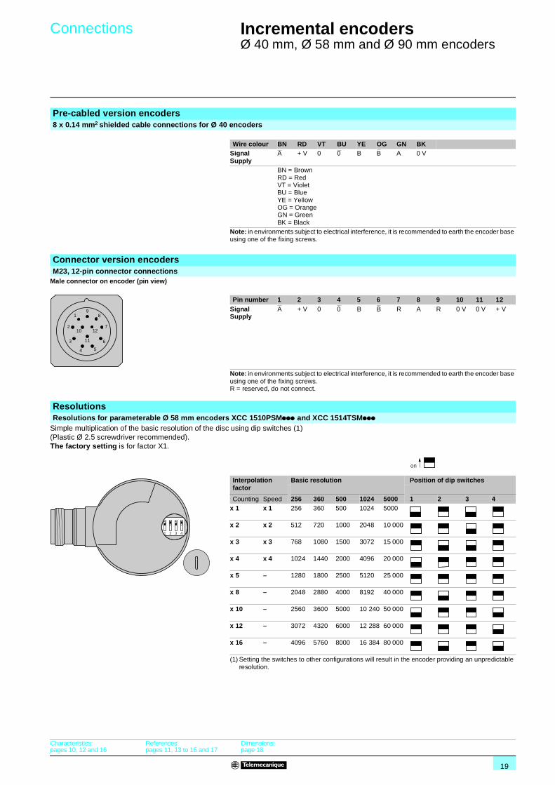
Connections 1 Incremental encoders 1
Ø 40 mm, Ø 58 mm and Ø 90 mm encoders
Pre-cabled version encoders8 x 0.14 mm2 shielded cable connections for Ø 40 encoders
Wire colour BN RD VT BU YE OG GN BKSignal Supply
A + V 0 0 B B A 0 V
BN = BrownRD = RedVT = VioletBU = BlueYE = YellowOG = OrangeGN = GreenBK = Black
Note: in environments subject to electrical interference, it is recommended to earth the encoder base using one of the fixing screws.
Connector version encodersM23, 12-pin connector connections
Male connector on encoder (pin view)
Pin number 1 2 3 4 5 6 7 8 9 10 11 12Signal Supply
A + V 0 0 B B R A R 0 V 0 V + V
Note: in environments subject to electrical interference, it is recommended to earth the encoder base using one of the fixing screws. R = reserved, do not connect.
Resolutions Resolutions for parameterable Ø 58 mm encoders XCC 1510PSMppp and XCC 1514TSMppp
Simple multiplication of the basic resolution of the disc using dip switches (1)(Plastic Ø 2.5 screwdriver recommended).The factory setting is for factor X1.
Interpolation factor
Basic resolution Position of dip switches
Counting Speed 256 360 500 1024 5000 1 2 3 4x 1 x 1 256 360 500 1024 5000
x 2 x 2 512 720 1000 2048 10 000
x 3 x 3 768 1080 1500 3072 15 000
x 4 x 4 1024 1440 2000 4096 20 000
x 5 – 1280 1800 2500 5120 25 000
x 8 – 2048 2880 4000 8192 40 000
x 10 – 2560 3600 5000 10 240 50 000
x 12 – 3072 4320 6000 12 288 60 000
x 16 – 4096 5760 8000 16 384 80 000
(1) Setting the switches to other configurations will result in the encoder providing an unpredictable resolution.
5
6
72
819
3
12
11
10
4
on
42 31
Characteristics:pages 10, 12 and 16
References:pages 11, 13 to 15 and 17
Dimensions:page 18
20
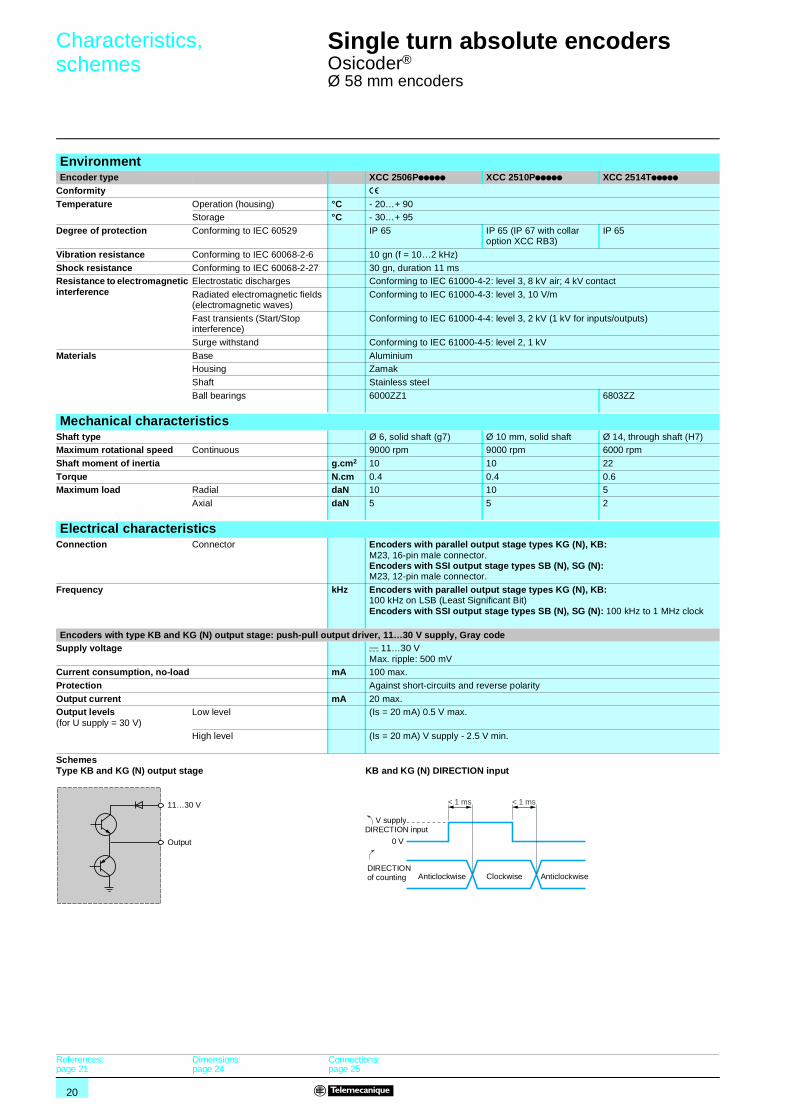
Characteristics, schemes 1
Single turn absolute encoders 1
Osicoder®
Ø 58 mm encoders
EnvironmentEncoder type XCC 2506Pppppp XCC 2510Pppppp XCC 2514Tppppp
Conformity eTemperature Operation (housing) °C - 20…+ 90
Storage °C - 30…+ 95
Degree of protection Conforming to IEC 60529 IP 65 IP 65 (IP 67 with collar option XCC RB3)
IP 65
Vibration resistance Conforming to IEC 60068-2-6 10 gn (f = 10…2 kHz)
Shock resistance Conforming to IEC 60068-2-27 30 gn, duration 11 msResistance to electromagnetic interference
Electrostatic discharges Conforming to IEC 61000-4-2: level 3, 8 kV air; 4 kV contact
Radiated electromagnetic fields (electromagnetic waves)
Conforming to IEC 61000-4-3: level 3, 10 V/m
Fast transients (Start/Stop interference)
Conforming to IEC 61000-4-4: level 3, 2 kV (1 kV for inputs/outputs)
Surge withstand Conforming to IEC 61000-4-5: level 2, 1 kV
Materials Base AluminiumHousing Zamak
Shaft Stainless steel
Ball bearings 6000ZZ1 6803ZZ
Mechanical characteristicsShaft type Ø 6, solid shaft (g7) Ø 10 mm, solid shaft Ø 14, through shaft (H7)Maximum rotational speed Continuous 9000 rpm 9000 rpm 6000 rpm
Shaft moment of inertia g.cm2 10 10 22
Torque N.cm 0.4 0.4 0.6Maximum load Radial daN 10 10 5
Axial daN 5 5 2
Electrical characteristicsConnection Connector Encoders with parallel output stage types KG (N), KB:
M23, 16-pin male connector.Encoders with SSI output stage types SB (N), SG (N): M23, 12-pin male connector.
Frequency kHz Encoders with parallel output stage types KG (N), KB: 100 kHz on LSB (Least Significant Bit)Encoders with SSI output stage types SB (N), SG (N): 100 kHz to 1 MHz clock
Encoders with type KB and KG (N) output stage: push-pull output driver, 11…30 V supply, Gray codeSupply voltage c 11…30 V
Max. ripple: 500 mVCurrent consumption, no-load mA 100 max.
Protection Against short-circuits and reverse polarity
Output current mA 20 max.Output levels(for U supply = 30 V)
Low level (Is = 20 mA) 0.5 V max.
High level (Is = 20 mA) V supply - 2.5 V min.
SchemesType KB and KG (N) output stage KB and KG (N) DIRECTION input
Output
11…30 V < 1 ms < 1 ms
V supplyDIRECTION input
0 V
DIRECTION of counting ClockwiseAnticlockwise Anticlockwise
References:page 21
Dimensions:page 24
Connections:page 25
21
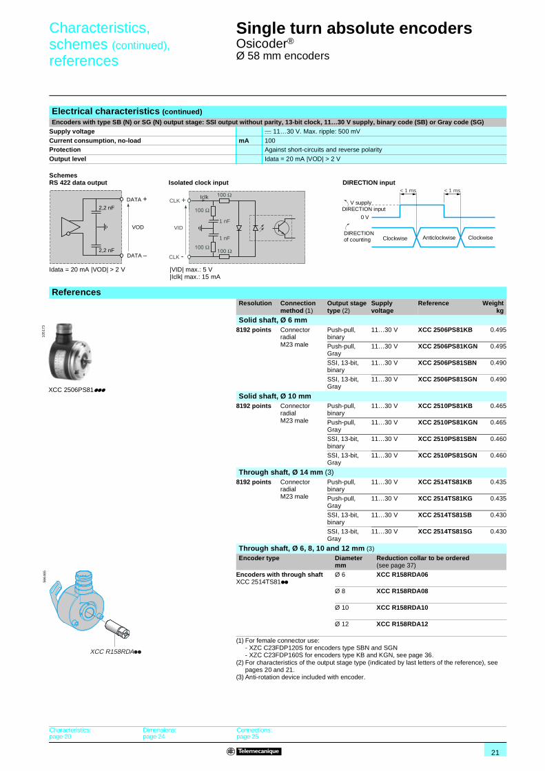
Characteristics, schemes (continued),
references 1
Single turn absolute encoders 1
Osicoder®
Ø 58 mm encoders
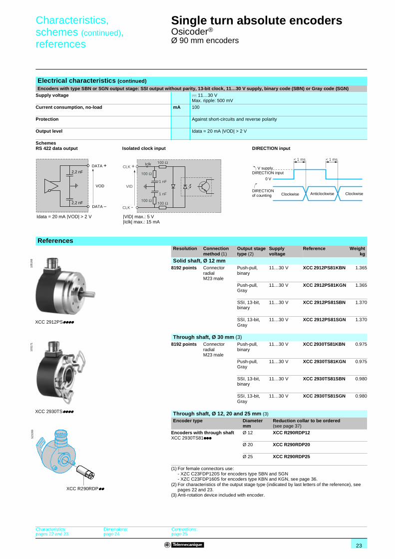
Electrical characteristics (continued)Encoders with type SB (N) or SG (N) output stage: SSI output without parity, 13-bit clock, 11…30 V supply, binary code (SB) or Gray code (SG)
Supply voltage c 11…30 V. Max. ripple: 500 mV
Current consumption, no-load mA 100Protection Against short-circuits and reverse polarity
Output level Idata = 20 mA |VOD| > 2 V
SchemesRS 422 data output Isolated clock input DIRECTION input
References
DATA +2,2 nF
2,2 nF
VOD
DATA –
Idata = 20 mA |VOD| > 2 V
CLK -
CLK
VID
+
1 nF
1 nF
Iclk
|VID| max.: 5 V|Iclk| max.: 15 mA
< 1 ms < 1 ms
V supplyDIRECTION input
0 V
DIRECTION of counting Clockwise ClockwiseAnticlockwise
Resolution Connection method (1)
Output stage type (2)
Supply voltage
Reference Weightkg
Solid shaft, Ø 6 mm8192 points Connector
radial M23 male
Push-pull, binary
11…30 V XCC 2506PS81KB 0.495
Push-pull, Gray
11…30 V XCC 2506PS81KGN 0.495
SSI, 13-bit, binary
11…30 V XCC 2506PS81SBN 0.490
SSI, 13-bit, Gray
11…30 V XCC 2506PS81SGN 0.490
Solid shaft, Ø 10 mm8192 points Connector
radial M23 male
Push-pull, binary
11…30 V XCC 2510PS81KB 0.465
Push-pull, Gray
11…30 V XCC 2510PS81KGN 0.465
SSI, 13-bit, binary
11…30 V XCC 2510PS81SBN 0.460
SSI, 13-bit, Gray
11…30 V XCC 2510PS81SGN 0.460
Through shaft, Ø 14 mm (3)8192 points Connector
radial M23 male
Push-pull, binary
11…30 V XCC 2514TS81KB 0.435
Push-pull, Gray
11…30 V XCC 2514TS81KG 0.435
SSI, 13-bit, binary
11…30 V XCC 2514TS81SB 0.430
SSI, 13-bit, Gray
11…30 V XCC 2514TS81SG 0.430
Through shaft, Ø 6, 8, 10 and 12 mm (3)
Encoder type Diametermm
Reduction collar to be ordered (see page 37)
Encoders with through shaft XCC 2514TS81pp
Ø 6 XCC R158RDA06
Ø 8 XCC R158RDA08
Ø 10 XCC R158RDA10
Ø 12 XCC R158RDA12
(1) For female connector use: - XZC C23FDP120S for encoders type SBN and SGN - XZC C23FDP160S for encoders type KB and KGN, see page 36.
(2) For characteristics of the output stage type (indicated by last letters of the reference), see pages 20 and 21.
(3) Anti-rotation device included with encoder.
XCC 2506PS81ppp
105
173
XCC R158RDA
566
465
Characteristics:page 20
Dimensions:page 24
Connections:page 25

22
Characteristics, schemes 1
Single turn absolute encoders 1
Osicoder®
Ø 90 mm encoders
EnvironmentEncoder type XCC 2912Pppppp XCC 2930Tppppp
Conformity eTemperature Operation (housing) °C - 20…+ 85
Storage °C - 40…+ 85
Degree of protection Conforming to IEC 60529 IP 66 IP 65
Vibration resistance Conforming to IEC 60068-2-6 10 gn (f = 10…2 kHz)Shock resistance Conforming to IEC 60068-2-27 30 gn, duration 11 ms
Resistance to electromagnetic interference
Electrostatic discharges Conforming to IEC 61000-4-2: level 3, 8 kV air; 4 kV contact
Radiated electromagnetic fields (electromagnetic waves)
Conforming to IEC 61000-4-3: level 3, 10 V/m
Fast transients (Start/Stop interference)
Conforming to IEC 61000-4-4: level 3, 2 kV (1 kV for inputs/outputs)
Surge withstand Conforming to IEC 61000-4-5: level 2, 1 kV
Materials Base AluminiumHousing Zamak
Shaft Stainless steel
Ball bearings 6001ZZ 6807
Mechanical characteristicsShaft type Ø 12, solid shaft (g6) Ø 30, through shaft (H7)Maximum rotational speed Continuous 6000 rpm 3600 rpm
Shaft moment of inertia g.cm2 150 500
Torque N.cm 1 2.5Maximum load Radial daN 20 8
Axial daN 10 5
Electrical characteristicsConnection Connector Encoders with parallel output stage types KB (N), KG (N):
M23, 16-pin male connector. Encoders with SSI output stage types SB (N), SG (N): M23, 12-pin male connector.
Frequency Encoders with parallel output stage types KB (N), KG (N): 100 kHz on LSB (Least Significant Bit)Encoders with SSI output stage types SB (N), SG (N): 100 kHz to 1 MHz clock
Encoders with type KBN or KGN output stage: push-pull output driver, 11…30 V supply, binary code (KBN) or Gray code (KGN)Supply voltage c 11…30 V. Max. ripple: 500 mV
Current consumption, no-load mA 100 max.
Protection Against short-circuits and reverse polarityOutput current mA 20 max.
Output levels(for U supply = 30 V)
Low level (Is = 20 mA) 0.5 V max.
High level (Is = 20 mA) V supply -3 V min.
SchemesType KB (N) and KG (N) output stage KB (N) and KG (N) DIRECTION input
Output
11…30 V < 1 ms < 1 ms
V supplyDIRECTION input
0 V
DIRECTION of counting ClockwiseAnticlockwise Anticlockwise
References:page 23
Dimensions:page 24
Connections:page 25
23
Characteristics,schemes (continued), references 1
Single turn absolute encoders 1
Osicoder®
Ø 90 mm encoders
Electrical characteristics (continued)Encoders with type SBN or SGN output stage: SSI output without parity, 13-bit clock, 11…30 V supply, binary code (SBN) or Gray code (SGN)
Supply voltage c 11…30 VMax. ripple: 500 mV
Current consumption, no-load mA 100
Protection Against short-circuits and reverse polarity
Output level Idata = 20 mA |VOD| > 2 V
SchemesRS 422 data output
Isolated clock input
DIRECTION input
References
DATA +2,2 nF
2,2 nF
VOD
DATA –
Idata = 20 mA |VOD| > 2 V
CLK -
CLK
VID
+
1 nF
1 nF
Iclk
|VID| max.: 5 V|Iclk| max.: 15 mA
< 1 ms < 1 ms
V supplyDIRECTION input
0 V
DIRECTION of counting Clockwise ClockwiseAnticlockwise
Resolution Connection method (1)
Output stage type (2)
Supply voltage
Reference Weightkg
Solid shaft, Ø 12 mm8192 points Connector
radial M23 male
Push-pull, binary
11…30 V XCC 2912PS81KBN 1.365
Push-pull, Gray
11…30 V XCC 2912PS81KGN 1.365
SSI, 13-bit, binary
11…30 V XCC 2912PS81SBN 1.370
SSI, 13-bit, Gray
11…30 V XCC 2912PS81SGN 1.370
Through shaft, Ø 30 mm (3)8192 points Connector
radial M23 male
Push-pull, binary
11…30 V XCC 2930TS81KBN 0.975
Push-pull, Gray
11…30 V XCC 2930TS81KGN 0.975
SSI, 13-bit, binary
11…30 V XCC 2930TS81SBN 0.980
SSI, 13-bit, Gray
11…30 V XCC 2930TS81SGN 0.980
Through shaft, Ø 12, 20 and 25 mm (3)
Encoder type Diametermm
Reduction collar to be ordered (see page 37)
Encoders with through shaft XCC 2930TS81ppp
Ø 12 XCC R290RDP12
Ø 20 XCC R290RDP20
Ø 25 XCC R290RDP25
(1) For female connectors use: - XZC C23FDP120S for encoders type SBN and SGN - XZC C23FDP160S for encoders type KBN and KGN, see page 36.
(2) For characteristics of the output stage type (indicated by last letters of the reference), see pages 22 and 23.
(3) Anti-rotation device included with encoder.
XCC 2912PSpppp
1051
68
XCC 2930TSpppp
1051
7152
320
0
XCC R290RDPpp
Characteristics:pages 22 and 23
Dimensions:page 24
Connections:page 25
24
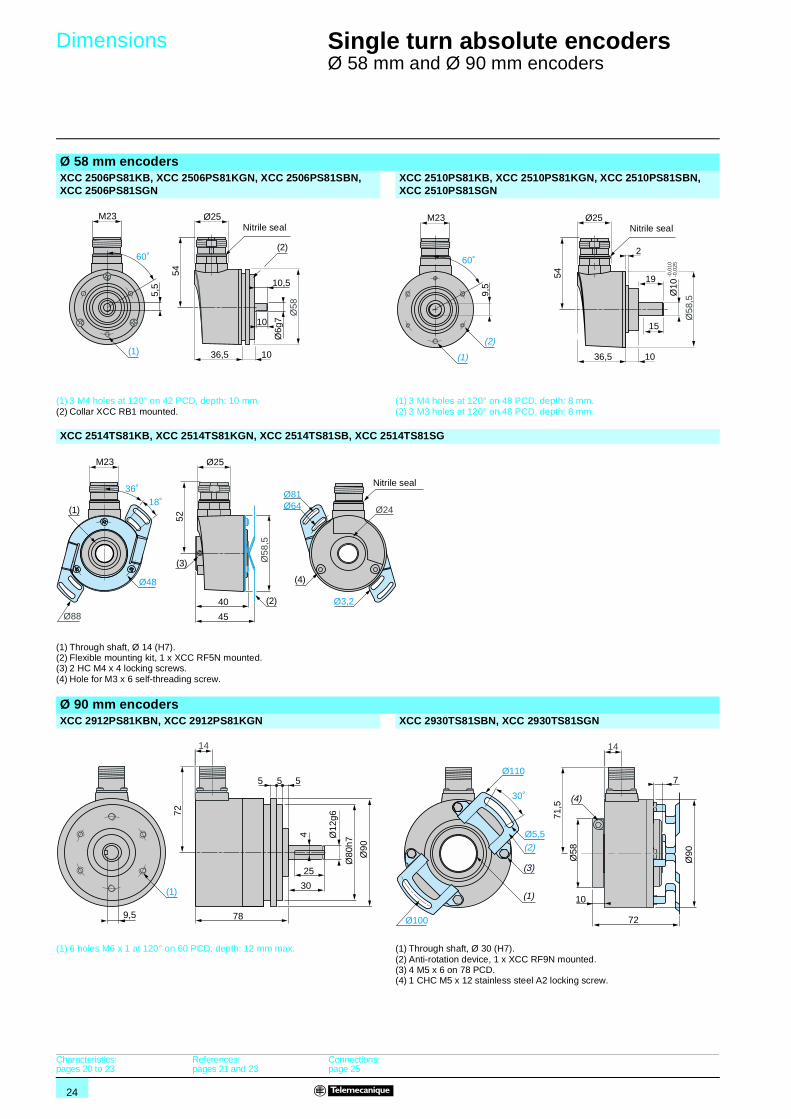
Dimensions 1 Single turn absolute encoders 1
Ø 58 mm and Ø 90 mm encoders
Ø 58 mm encodersXCC 2506PS81KB, XCC 2506PS81KGN, XCC 2506PS81SBN, XCC 2506PS81SGN
XCC 2510PS81KB, XCC 2510PS81KGN, XCC 2510PS81SBN, XCC 2510PS81SGN
(1) 3 M4 holes at 120° on 42 PCD, depth: 10 mm.(2) Collar XCC RB1 mounted.
(1) 3 M4 holes at 120° on 48 PCD, depth: 8 mm.(2) 3 M3 holes at 120° on 48 PCD, depth: 8 mm.
XCC 2514TS81KB, XCC 2514TS81KGN, XCC 2514TS81SB, XCC 2514TS81SG
(1) Through shaft, Ø 14 (H7).(2) Flexible mounting kit, 1 x XCC RF5N mounted.(3) 2 HC M4 x 4 locking screws.(4) Hole for M3 x 6 self-threading screw.
Ø 90 mm encodersXCC 2912PS81KBN, XCC 2912PS81KGN XCC 2930TS81SBN, XCC 2930TS81SGN
(1) 6 holes M6 x 1 at 120° on 60 PCD, depth: 12 mm max. (1) Through shaft, Ø 30 (H7).(2) Anti-rotation device, 1 x XCC RF9N mounted.(3) 4 M5 x 6 on 78 PCD.(4) 1 CHC M5 x 12 stainless steel A2 locking screw.
60˚(2)
1036,5
Ø58
10,5
10
Ø6g
7
M23 Ø25
(1)
5,5
54
Nitrile sealM23
9,5
(2)
(1)
54
Ø58
,5
Ø25
10
19
2
15
36,5
Ø10
60˚
-0,0
10-0
,025
Nitrile seal
Ø81Ø64
52
Ø58
,5
Ø88
Ø24
Ø25M23
40
45
Ø3,2
18˚36˚
(2)
(4)
(1)
(3)
Ø48
Nitrile seal
72
14
5
4
5
25
30
78
Ø12
g6
Ø80
h7
Ø90
5
(1)
9,5
Ø90Ø58
71,5
30˚
Ø5,5
(1)
(4)
10
72
7
14
Ø110
Ø100
(3)
(2)
Characteristics:pages 20 to 23
References:pages 21 and 23
Connections:page 25
25
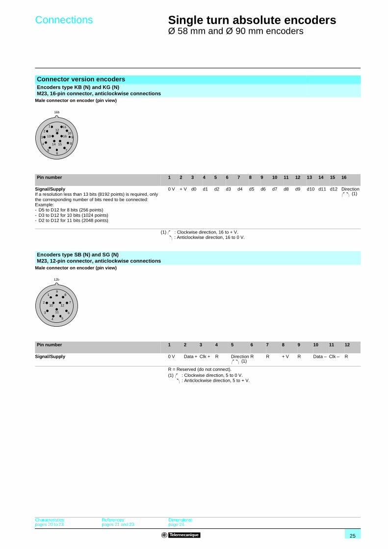
Connections 1 Single turn absolute encoders 1
Ø 58 mm and Ø 90 mm encoders
Connector version encodersEncoders type KB (N) and KG (N)M23, 16-pin connector, anticlockwise connections
Male connector on encoder (pin view)
Pin number 1 2 3 4 5 6 7 8 9 10 11 12 13 14 15 16
Signal/SupplyIf a resolution less than 13 bits (8192 points) is required, only the corresponding number of bits need to be connected: Example: - D5 to D12 for 8 bits (256 points)- D3 to D12 for 10 bits (1024 points)- D2 to D12 for 11 bits (2048 points)
0 V + V d0 d1 d2 d3 d4 d5 d6 d7 d8 d9 d10 d11 d12 Direction
(1) : Clockwise direction, 16 to + V. : Anticlockwise direction, 16 to 0 V.
Encoders type SB (N) and SG (N)M23, 12-pin connector, anticlockwise connections
Male connector on encoder (pin view)
Pin number 1 2 3 4 5 6 7 8 9 10 11 12
Signal/Supply 0 V Data + Clk + R Direction R R + V R Data – Clk – R
R = Reserved (do not connect).(1) : Clockwise direction, 5 to 0 V.
: Anticlockwise direction, 5 to + V.
56
7
2
3
8
9
12
1613
14 15
11
10
1
16b
4
(1)
5
6
72
819
12b
3
12
11
10
4
(1)
Characteristics:pages 20 to 23
References:pages 21 and 23
Dimensions:page 24
26
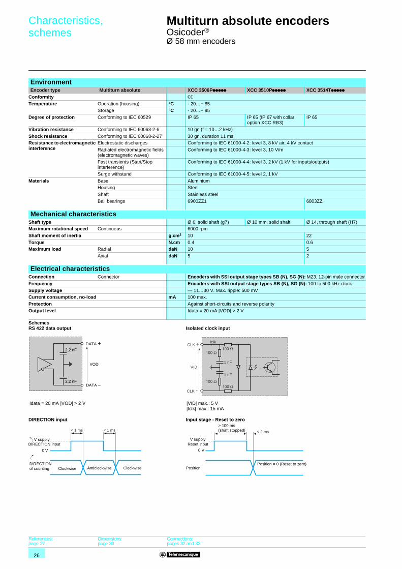
Characteristics, schemes 1
Multiturn absolute encoders 1
Osicoder® Ø 58 mm encoders
EnvironmentEncoder type Multiturn absolute XCC 3506Pppppp XCC 3510Pppppp XCC 3514Tppppp
Conformity eTemperature Operation (housing) °C - 20…+ 85
Storage °C - 20…+ 85
Degree of protection Conforming to IEC 60529 IP 65 IP 65 (IP 67 with collar option XCC RB3)
IP 65
Vibration resistance Conforming to IEC 60068-2-6 10 gn (f = 10…2 kHz)
Shock resistance Conforming to IEC 60068-2-27 30 gn, duration 11 msResistance to electromagnetic interference
Electrostatic discharges Conforming to IEC 61000-4-2: level 3, 8 kV air; 4 kV contact
Radiated electromagnetic fields (electromagnetic waves)
Conforming to IEC 61000-4-3: level 3, 10 V/m
Fast transients (Start/Stop interference)
Conforming to IEC 61000-4-4: level 3, 2 kV (1 kV for inputs/outputs)
Surge withstand Conforming to IEC 61000-4-5: level 2, 1 kV
Materials Base AluminiumHousing Steel
Shaft Stainless steel
Ball bearings 6900ZZ1 6803ZZ
Mechanical characteristicsShaft type Ø 6, solid shaft (g7) Ø 10 mm, solid shaft Ø 14, through shaft (H7)Maximum rotational speed Continuous 6000 rpm
Shaft moment of inertia g.cm2 10 22
Torque N.cm 0.4 0.6Maximum load Radial daN 10 5
Axial daN 5 2
Electrical characteristicsConnection Connector Encoders with SSI output stage types SB (N), SG (N): M23, 12-pin male connector
Frequency Encoders with SSI output stage types SB (N), SG (N): 100 to 500 kHz clock
Supply voltage c 11…30 V. Max. ripple: 500 mVCurrent consumption, no-load mA 100 max.
Protection Against short-circuits and reverse polarity
Output level Idata = 20 mA |VOD| > 2 V
SchemesRS 422 data output Isolated clock input
DIRECTION input Input stage - Reset to zero
DATA +2,2 nF
2,2 nF
VOD
DATA –
Idata = 20 mA |VOD| > 2 V
CLK -
CLK
VID
+
1 nF
1 nF
Iclk
|VID| max.: 5 V|Iclk| max.: 15 mA
< 1 ms < 1 ms
V supplyDIRECTION input
0 V
DIRECTION of counting Clockwise ClockwiseAnticlockwise
< 2 ms
V supplyReset input
0 V
PositionPosition = 0 (Reset to zero)
> 100 ms(shaft stopped)
References:page 27
Dimensions:page 30
Connections:pages 32 and 33
27
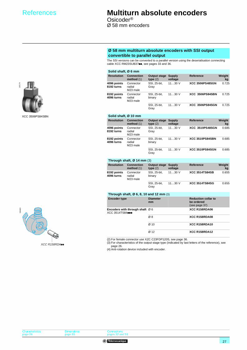
References 1 Multiturn absolute encoders 1
Osicoder® Ø 58 mm encoders
Ø 58 mm multiturn absolute encoders with SSI output convertible to parallel output
The SSI versions can be converted to a parallel version using the deserialisation connecting cable XCC RM23SUB37pp, see pages 33 and 36.
Solid shaft, Ø 6 mmResolution Connection
method (1)Output stage type (2)
Supply voltage
Reference Weightkg
4096 points 8192 turns
Connector radial M23 male
SSI, 25-bit, Gray
11…30 V XCC 3506PS48SGN 0.725
8192 points 4096 turns
Connector radial M23 male
SSI, 25-bit, binary
11…30 V XCC 3506PS84SBN 0.725
SSI, 25-bit, Gray
11…30 V XCC 3506PS84SGN 0.725
Solid shaft, Ø 10 mmResolution Connection
method (1)Output stage type (2)
Supply voltage
Reference Weightkg
4096 points 8192 turns
Connector radial M23 male
SSI, 25-bit, Gray
11…30 V XCC 3510PS48SGN 0.685
8192 points 4096 turns
Connector radial M23 male
SSI, 25-bit, binary
11…30 V XCC 3510PS84SBN 0.685
SSI, 25-bit, Gray
11…30 V XCC 3510PS84SGN 0.685
Through shaft, Ø 14 mm (3)Resolution Connection
method (1)Output stage type (2)
Supply voltage
Reference Weightkg
8192 points 4096 turns
Connector radial M23 male
SSI, 25-bit, binary
11…30 V XCC 3514TS84SB 0.655
SSI, 25-bit, Gray
11…30 V XCC 3514TS84SG 0.655
Through shaft, Ø 6, 8, 10 and 12 mm (3)
Encoder type Diametermm
Reduction collar to be ordered (see page 37)
Encoders with through shaft XCC 3514TS84ppp
Ø 6 XCC R158RDA06
Ø 8 XCC R158RDA08
Ø 10 XCC R158RDA10
Ø 12 XCC R158RDA12
(2) For female connector use XZC C23FDP120S, see page 36.(3) For characteristics of the output stage type (indicated by last letters of the reference), see
page 26.(4) Anti-rotation device included with encoder.
XCC 3506PS84SBN
1051
74
XCC R158RDA
566
465
Characteristics:page 26
Dimensions:page 30
Connections:pages 32 and 33
28
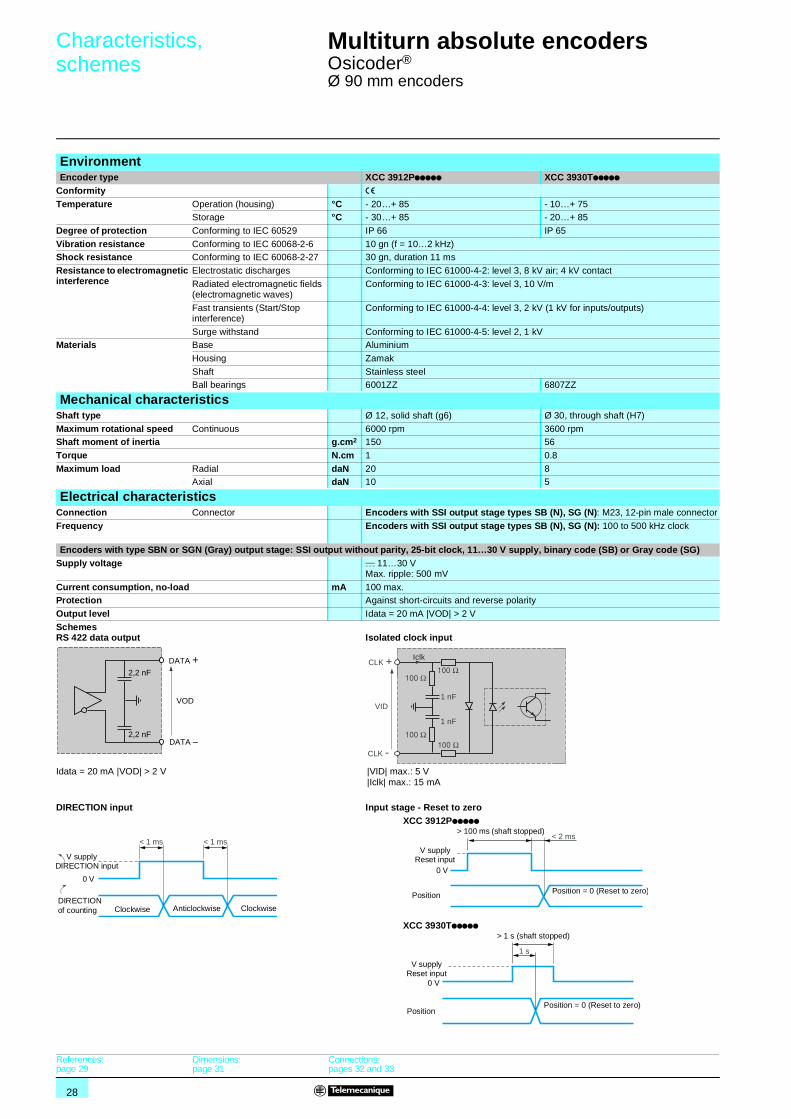
Characteristics, schemes 1
Multiturn absolute encoders 1
Osicoder®
Ø 90 mm encoders
EnvironmentEncoder type XCC 3912Pppppp XCC 3930Tppppp
Conformity eTemperature Operation (housing) °C - 20…+ 85 - 10…+ 75
Storage °C - 30…+ 85 - 20…+ 85
Degree of protection Conforming to IEC 60529 IP 66 IP 65
Vibration resistance Conforming to IEC 60068-2-6 10 gn (f = 10…2 kHz)Shock resistance Conforming to IEC 60068-2-27 30 gn, duration 11 ms
Resistance to electromagnetic interference
Electrostatic discharges Conforming to IEC 61000-4-2: level 3, 8 kV air; 4 kV contact
Radiated electromagnetic fields (electromagnetic waves)
Conforming to IEC 61000-4-3: level 3, 10 V/m
Fast transients (Start/Stop interference)
Conforming to IEC 61000-4-4: level 3, 2 kV (1 kV for inputs/outputs)
Surge withstand Conforming to IEC 61000-4-5: level 2, 1 kVMaterials Base Aluminium
Housing Zamak
Shaft Stainless steelBall bearings 6001ZZ 6807ZZ
Mechanical characteristicsShaft type Ø 12, solid shaft (g6) Ø 30, through shaft (H7)
Maximum rotational speed Continuous 6000 rpm 3600 rpmShaft moment of inertia g.cm2 150 56
Torque N.cm 1 0.8
Maximum load Radial daN 20 8Axial daN 10 5
Electrical characteristicsConnection Connector Encoders with SSI output stage types SB (N), SG (N): M23, 12-pin male connector
Frequency Encoders with SSI output stage types SB (N), SG (N): 100 to 500 kHz clock
Encoders with type SBN or SGN (Gray) output stage: SSI output without parity, 25-bit clock, 11…30 V supply, binary code (SB) or Gray code (SG)Supply voltage c 11…30 V
Max. ripple: 500 mV
Current consumption, no-load mA 100 max.Protection Against short-circuits and reverse polarity
Output level Idata = 20 mA |VOD| > 2 V
SchemesRS 422 data output Isolated clock input
DIRECTION input Input stage - Reset to zero XCC 3912Pppppp
XCC 3930Tppppp
DATA +2,2 nF
2,2 nF
VOD
DATA –
Idata = 20 mA |VOD| > 2 V
CLK -
CLK
VID
+
1 nF
1 nF
Iclk
|VID| max.: 5 V|Iclk| max.: 15 mA
< 1 ms < 1 ms
V supplyDIRECTION input
0 V
DIRECTION of counting Clockwise ClockwiseAnticlockwise
< 2 ms
V supplyReset input
0 V
Position Position = 0 (Reset to zero)
> 100 ms (shaft stopped)
1 s
V supplyReset input
0 V
PositionPosition = 0 (Reset to zero)
> 1 s (shaft stopped)
References:page 29
Dimensions:page 31
Connections:pages 32 and 33
29
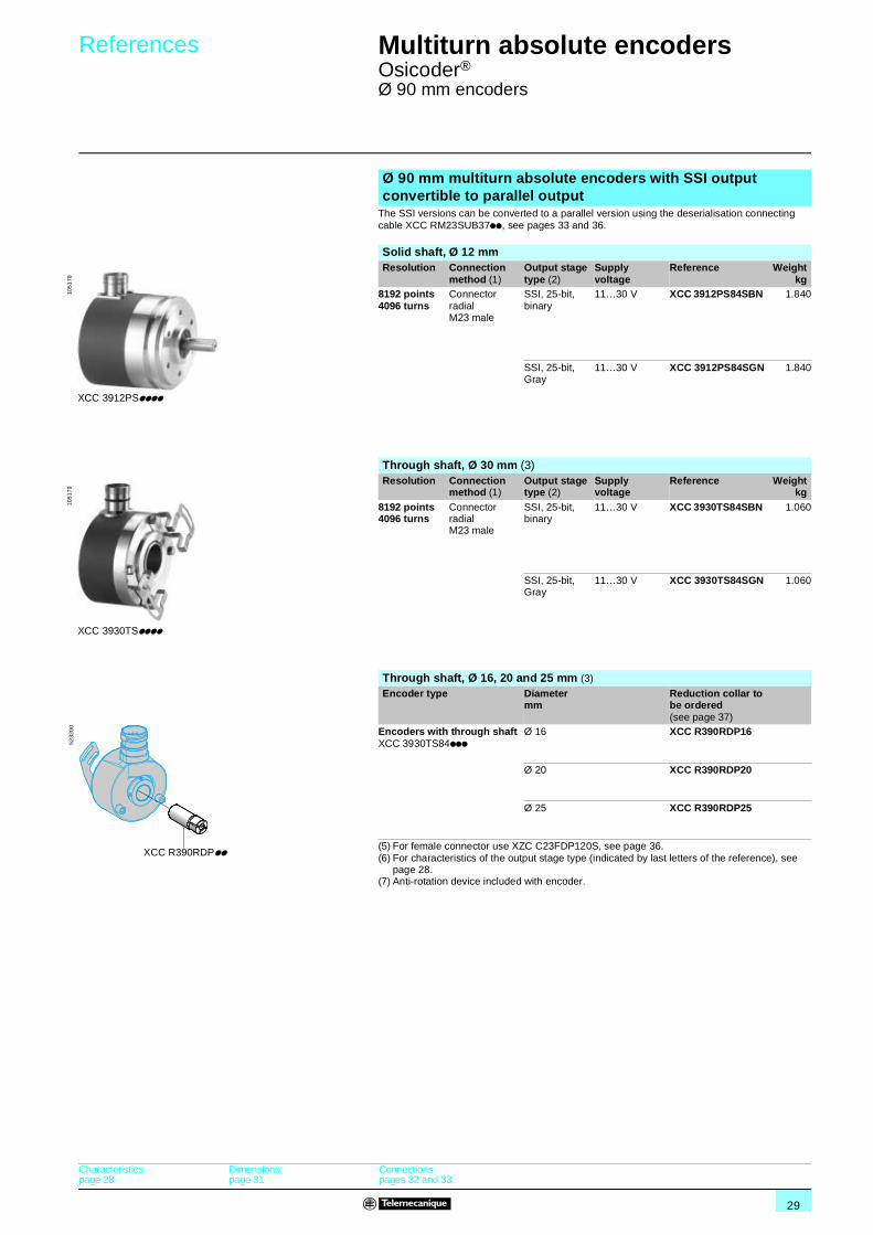
References 1 Multiturn absolute encoders 1
Osicoder®
Ø 90 mm encoders
Ø 90 mm multiturn absolute encoders with SSI output convertible to parallel output
The SSI versions can be converted to a parallel version using the deserialisation connecting cable XCC RM23SUB37pp, see pages 33 and 36.
Solid shaft, Ø 12 mmResolution Connection
method (1)Output stage type (2)
Supply voltage
Reference Weightkg
8192 points 4096 turns
Connector radial M23 male
SSI, 25-bit, binary
11…30 V XCC 3912PS84SBN 1.840
SSI, 25-bit, Gray
11…30 V XCC 3912PS84SGN 1.840
Through shaft, Ø 30 mm (3)Resolution Connection
method (1)Output stage type (2)
Supply voltage
Reference Weightkg
8192 points 4096 turns
Connector radial M23 male
SSI, 25-bit, binary
11…30 V XCC 3930TS84SBN 1.060
SSI, 25-bit, Gray
11…30 V XCC 3930TS84SGN 1.060
Through shaft, Ø 16, 20 and 25 mm (3)
Encoder type Diametermm
Reduction collar to be ordered (see page 37)
Encoders with through shaft XCC 3930TS84ppp
Ø 16 XCC R390RDP16
Ø 20 XCC R390RDP20
Ø 25 XCC R390RDP25
(5) For female connector use XZC C23FDP120S, see page 36.(6) For characteristics of the output stage type (indicated by last letters of the reference), see
page 28.(7) Anti-rotation device included with encoder.
XCC 3912PSpppp
1051
78
XCC 3930TSpppp
105
179
5232
00
XCC R390RDPpp
Characteristics:page 28
Dimensions:page 31
Connections:pages 32 and 33
30
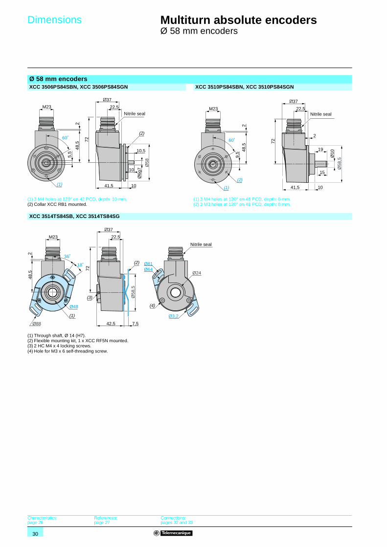
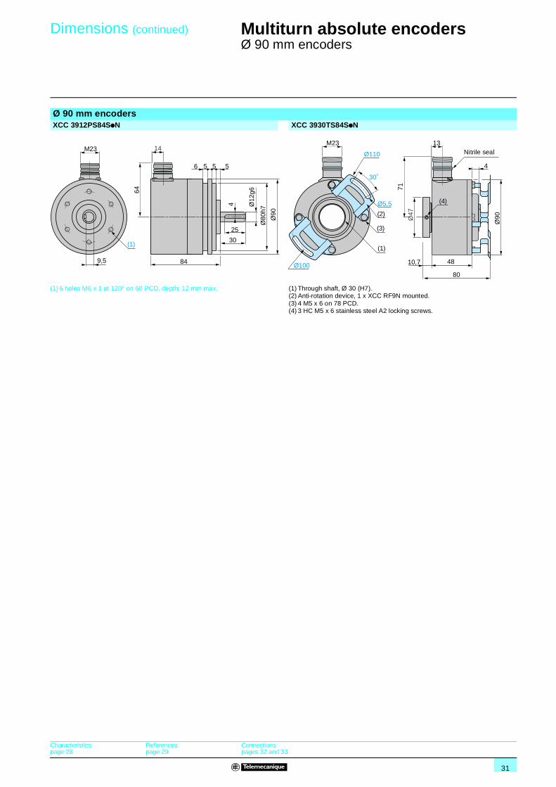
Dimensions 1 Multiturn absolute encoders 1
Ø 58 mm encoders
Ø 58 mm encodersXCC 3506PS84SBN, XCC 3506PS84SGN XCC 3510PS84SBN, XCC 3510PS84SGN
(1) 3 M4 holes at 120° on 42 PCD, depth: 10 mm.(2) Collar XCC RB1 mounted.
(1) 3 M4 holes at 120° on 48 PCD, depth: 8 mm.(2) 3 M3 holes at 120° on 48 PCD, depth: 8 mm.
XCC 3514TS84SB, XCC 3514TS84SG
(1) Through shaft, Ø 14 (H7).(2) Flexible mounting kit, 1 x XCC RF5N mounted.(3) 2 HC M4 x 4 locking screws.(4) Hole for M3 x 6 self-threading screw.
(2)
1041,5
Ø58
10,5
37
22,5
10
Ø6g
7
72
M23
48,5
2
60˚
(1)
5,5
Nitrile sealM23
9,5
(2)
(1)
Ø58
,5
10
19
2
15
41,5
Ø10
60˚
37
22,5
72
48,5
2
Nitrile seal
Ø81Ø64
M23
Ø58
,5
Ø88
Ø48
42,5 7,5
Ø3,2
18˚
36˚(2)
(4)
(1)
48,5
2
(3)
37
22,5
Ø24
72
Nitrile seal
Characteristics:page 26
References:page 27
Connections:pages 32 and 33
31
Dimensions (continued) 1 Multiturn absolute encoders 1
Ø 90 mm encoders
Ø 90 mm encodersXCC 3912PS84SpN XCC 3930TS84SpN
(1) 6 holes M6 x 1 at 120° on 60 PCD, depth: 12 mm max. (1) Through shaft, Ø 30 (H7).(2) Anti-rotation device, 1 x XCC RF9N mounted.(3) 4 M5 x 6 on 78 PCD.(4) 3 HC M5 x 6 stainless steel A2 locking screws.
M23
64
56
4
5
25
30
84
Ø12
g6
Ø80
h7
Ø90
5
(1)
9,5
14M23 13
Ø110
Ø100
Ø90
71
30˚
Ø5,5
(1)
(3)
(4)
(2)
10,7
80
48
4
Ø47
Nitrile seal
Characteristics:page 28
References:page 29
Connections:pages 32 and 33

32
Connections 1 Multiturn absolute encoders 1
Ø 58 mm and Ø 90 mm encoders
Connector version encodersEncoders with SSI output (types SBN and SGN)M23, 12-pin connector, anticlockwise connections
Male connector on encoder (pin view)
Twisted cable pairs + general shielding must be used.Pin number 1 2 3 4 5 6 7 8 9 10 11 12
Signal/Supply 0 V Data + Clk + R Direction Reset R + V R Data – Clk – R
R = Reserved (do not connect).(1) : Clockwise direction, : Anticlockwise direction.
Selection of code progression directionThe DIRECTION input enables the code progression to match the rotational direction of the encoder shaft (clockwise or anticlockwise).Clockwise direction: connect pin 5 to 0 V.Anticlockwise direction: connect pin 5 to + V.
Reset to zeroThe RESET input enables the encoder to be set to the zero position.It is actuated by applying an 11…30 V d.c. supply to pin 6, whilst the shaft is stopped, for the following times:b over 100 ms for XCC 3506, XCC 3510 and XCC 3912,b over 1 s for XCC 3930T.
Following a reset to zero, pin 6 must be reconnected to 0 V.Note: in environments subject to electrical interference, it is recommended to earth the encoder base using one of the fixing screws.
5
6
72
819
12b
3
12
11
10
4
(1)
Characteristics:pages 26 and 28
References:pages 27 and 29
Dimensions:pages 30 and 31
33
Connections (continued) 1 Multiturn absolute encoders 1
Ø 58 mm and Ø 90 mm encoders
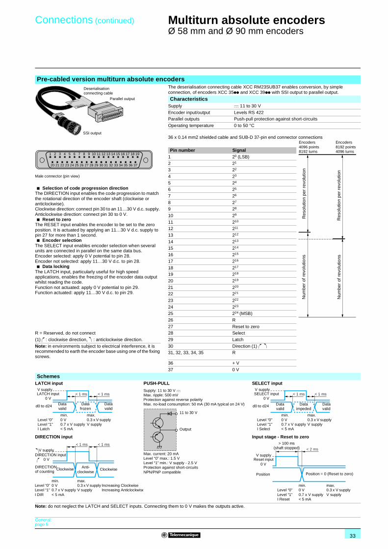
Pre-cabled version multiturn absolute encodersThe deserialisation connecting cable XCC RM23SUB37 enables conversion, by simple connection, of encoders XCC 35pp and XCC 39pp with SSI output to parallel output.
CharacteristicsSupply c 11 to 30 V
Encoder input/output Levels RS 422Parallel outputs Push-pull protection against short-circuits
Operating temperature 0 to 50 °C
36 x 0.14 mm2 shielded cable and SUB-D 37-pin end connector connections
Pin number Signal1 20 (LSB)
2 21
3 22
Male connector (pin view) 4 23
b Selection of code progression directionThe DIRECTION input enables the code progression to match the rotational direction of the encoder shaft (clockwise or anticlockwise).Clockwise direction: connect pin 30 to an 11…30 V d.c. supply.Anticlockwise direction: connect pin 30 to 0 V.b Reset to zero
The RESET input enables the encoder to be set to the zero position. It is actuated by applying an 11…30 V d.c. supply to pin 27 for more than 1 second. b Encoder selection
The SELECT input enables encoder selection when several units are connected in parallel on the same data bus.Encoder selected: apply 0 V potential to pin 28.Encoder not selected: apply 11…30 V d.c. to pin 28.b Data locking
The LATCH input, particularly useful for high speed applications, enables the freezing of the encoder data output whilst reading the code.Function not actuated: apply 0 V potential to pin 29.Function actuated: apply 11…30 V d.c. to pin 29.
5 24
6 25
7 26
8 27
9 28
10 29
11 210
12 211
13 212
14 213
15 214
16 215
17 216
18 217
19 218
20 219
21 220
22 221
23 222
24 223
25 224 (MSB)
26 R
27 Reset to zeroR = Reserved, do not connect 28 Select
(1) : clockwise direction, : anticlockwise direction. 29 Latch
Note: in environments subject to electrical interference, it is recommended to earth the encoder base using one of the fixing screws.
30 Direction (1) 31, 32, 33, 34, 35 R
36 + V
37 0 V
SchemesLATCH input PUSH-PULL SELECT input
DIRECTION input Input stage - Reset to zero
Note: do not neglect the LATCH and SELECT inputs. Connecting them to 0 V makes the outputs active.
810
12
(…)Data (…)Clk
+V
119 8250-053
58
RR
XCC-RM23SUB37NG
France0514SSIGRAY =>NPNGRAY
Parallel output
SSI output
Deserialisation connecting cable
Encoders 4096 points 8192 turns
Encoders 8192 points 4096 turns
Res
olut
ion
per
revo
lutio
nN
umbe
r of
rev
olut
ions
Num
ber
of r
evol
utio
nsR
esol
utio
n pe
r re
volu
tion
1 2 3 4 5 6 7 8 9 10 11 12 13 14 15 16 17 18 19
20 21 22 23 24 25 26 27 28 29 30 31 32 33 34 35 36 37
< 1 ms < 1 ms
Datafrozen
Datavalid
Datavalid
V supplyLATCH input
0 V
d0 to d24
Level “0”Level “1”I Latch
min.0 V0.7 x V supply< 5 mA
max.0.3 x V supplyV supply
Supply: 11 to 30 V cMax. ripple: 500 mVProtection against reverse polarityMax. no-load consumption: 50 mA (30 mA typical on 24 V)
Max. current: 20 mALevel “0” max.: 1.5 VLevel “1” min.: V supply - 2.5 VProtection against short-circuitsNPN/PNP compatible
11 to 30 V
Output
< 1 ms < 1 ms
Dataimpeded
Datavalid
Datavalid
V supplySELECT input
0 V
d0 to d24
Level “0”Level “1”I Select
min.0 V0.7 x V supply< 5 mA
max.0.3 x V supplyV supply
< 1 ms < 1 ms
Anti-clockwise
ClockwiseClockwise
V supplyDIRECTION input
0 V
DIRECTION of counting
Level “0”Level “1”I DIR
min.0 V0.7 x V supply< 5 mA
max.0.3 x V supplyV supply
Increasing ClockwiseIncreasing Anticlockwise
< 2 ms
Position Position = 0 (Reset to zero)
V supplyReset input
0 V
Level “0”Level “1”I Reset
min.0 V0.7 x V supply< 5 mA
max.0.3 x V supplyV supply
> 100 ms(shaft stopped)
General:page 5
34
Characteristics 1 Rotary encoders 1
Osicoder®
Accessories
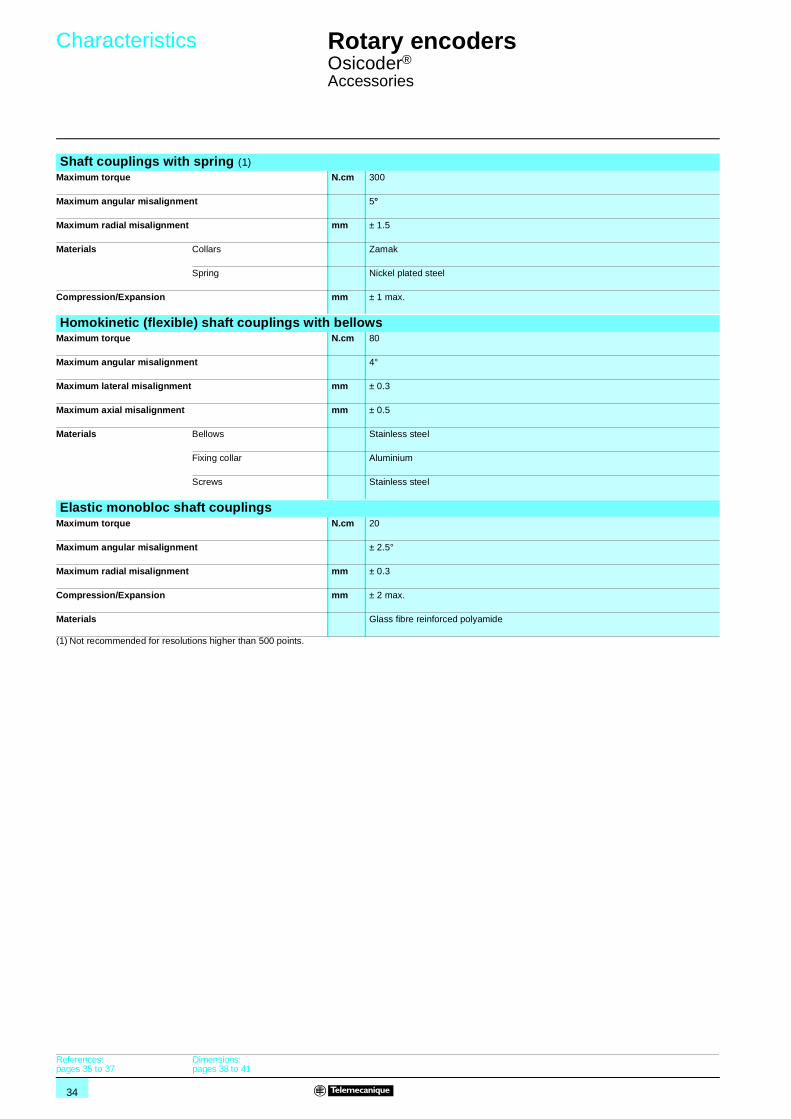
(1) Not recommended for resolutions higher than 500 points.
Shaft couplings with spring (1)Maximum torque N.cm 300
Maximum angular misalignment 5°
Maximum radial misalignment mm ± 1.5
Materials Collars Zamak
Spring Nickel plated steel
Compression/Expansion mm ± 1 max.
Homokinetic (flexible) shaft couplings with bellowsMaximum torque N.cm 80
Maximum angular misalignment 4°
Maximum lateral misalignment mm ± 0.3
Maximum axial misalignment mm ± 0.5
Materials Bellows Stainless steel
Fixing collar Aluminium
Screws Stainless steel
Elastic monobloc shaft couplingsMaximum torque N.cm 20
Maximum angular misalignment ± 2.5°
Maximum radial misalignment mm ± 0.3
Compression/Expansion mm ± 2 max.
Materials Glass fibre reinforced polyamide
References:pages 35 to 37
Dimensions:pages 38 to 41
35
References 1 Rotary encoders 1
Osicoder®
Accessories
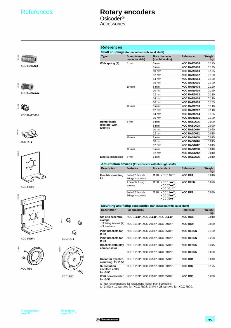
(1) Not recommended for resolutions higher than 500 points.(2) 3 M3 x 12 screws for XCC RG5, 3 M4 x 25 screws for XCC RG9.
ReferencesShaft couplings (for encoders with solid shaft)Type Bore diameter
(encoder side)Bore diameter (machine side)
Reference Weightkg
With spring (1) 6 mm 6 mm XCC RAR0606 0.125
8 mm XCC RAR0608 0.12510 mm XCC RAR0610 0.125
12 mm XCC RAR0612 0.120
14 mm XCC RAR0614 0.12016 mm XCC RAR0616 0.120
10 mm 8 mm XCC RAR1008 0.120
10 mm XCC RAR1010 0.12012 mm XCC RAR1012 0.110
14 mm XCC RAR1014 0.110
16 mm XCC RAR1016 0.10512 mm 8 mm XCC RAR1208 0.110
12 mm XCC RAR1212 0.110
14 mm XCC RAR1214 0.10516 mm XCC RAR1216 0.100
Homokinetic (flexible) with bellows
6 mm 6 mm XCC RAS0606 0.020
8 mm XCC RAS0608 0.02010 mm XCC RAS0610 0.020
12 mm XCC RAS0612 0.015
10 mm 8 mm XCC RAS1008 0.01510 mm XCC RAS1010 0.015
12 mm XCC RAS1012 0.015
12 mm 8 mm XCC RAS1208 0.01012 mm XCC RAS1212 0.010
Elastic, monobloc 6 mm 6 mm XCC RAE0606 0.010
Anti-rotation devices (for encoders with through shaft)Description Features For encoders Reference Weight
kgFlexible mounting kit
Set of 2 flexible fixings + screws
Ø 40 XCC 1406T XCC RF4 0.010
1 flexible fixing + screws
Ø 58 XCC 15ppT, XCC 25ppT, XCC 3514T
XCC RF5N 0.020
Set of 2 flexible fixings + screws
Ø 90 XCC 19ppT, XCC 29ppT, XCC 39ppT
XCC RF9 0.030
Mounting and fixing accessories (for encoders with solid shaft)Description For encoders Reference Weight
kgSet of 3 eccentric clamps+ 3 fixing screws (2)+ 3 washers
XCC 15ppP, XCC 25ppP, XCC 35ppP XCC RG5 0.010
XCC 1912P, XCC 2912P, XCC 3912P XCC RG9 0.030
Plain brackets for Ø 58
XCC 1510P, XCC 2510P, XCC 3510P XCC RE5SN 0.130
Plain brackets for Ø 90
XCC 1912P, XCC 2912P, XCC 3912P XCC RE9SN 0.290
Brackets with play compensator
XCC 1510P, XCC 2510P, XCC 3510P XCC RE5RN 0.345
XCC 1912P, XCC 2912P, XCC 3912P XCC RE9RN 0.890
Collar for synchro mounting, for Ø 58
XCC 1510P, XCC 2510P, XCC 3510P XCC RB1 0.040
Substitution interface collar for Ø 90
XCC 1912P, XCC 2912P, XCC 3912P XCC RB2 0.175
IP 67 sealed collar for Ø 58
XCC 1510P, XCC 2510P, XCC 3510P XCC RB3 0.030
105
191
XCC RARppp
1051
92
XCC RASpppp
8063
09
XCC RAE0606
8063
11
XCC RFp
XCC RGp
806
312
5664
61
XCC RE9S
566
462
XCC REpR
XCC RB1
566
463
XCC RB2
566
464
Characteristics:page 34
Dimensions:pages 38 to 41
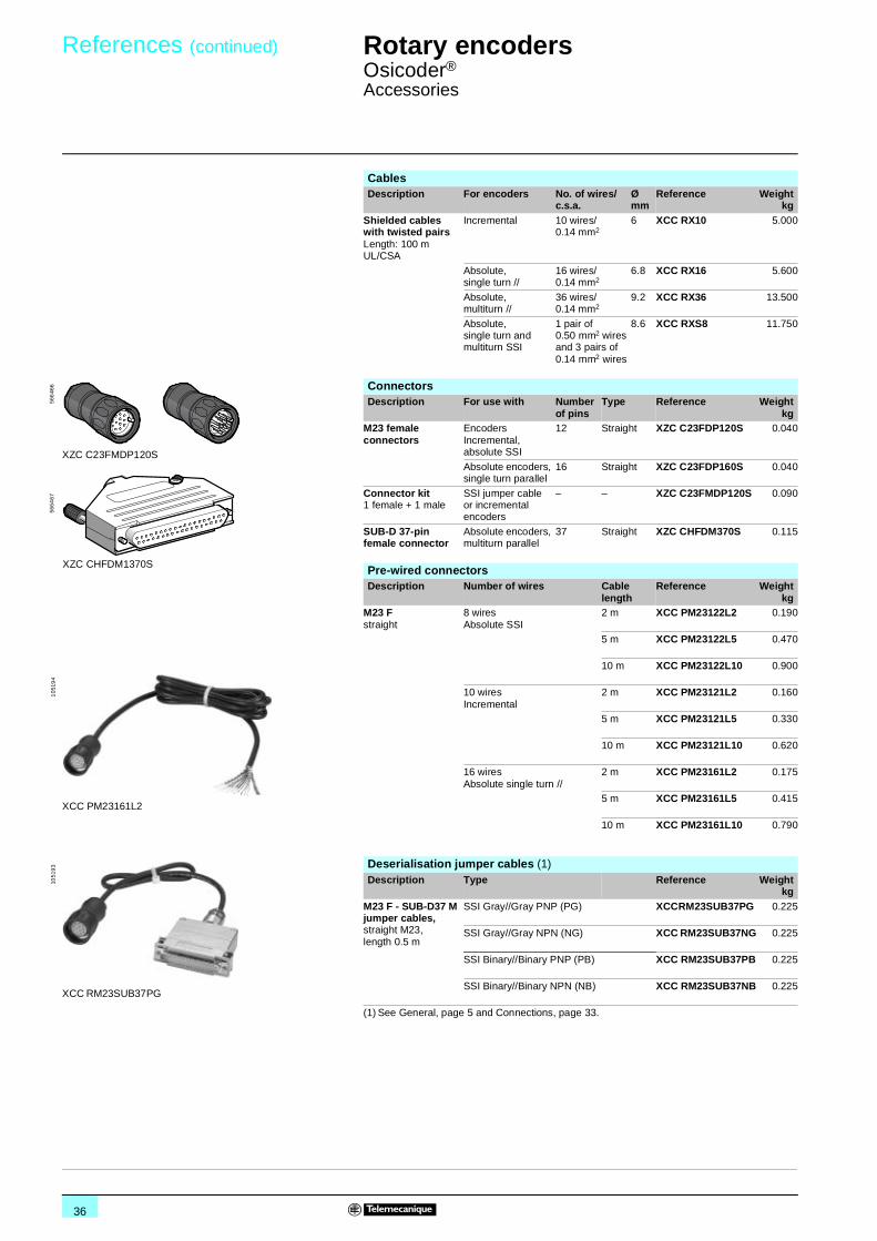
36
References (continued) 1 Rotary encoders 1
Osicoder®
Accessories
CablesDescription For encoders No. of wires/
c.s.a.Ø mm
Reference Weightkg
Shielded cables with twisted pairs Length: 100 m UL/CSA
Incremental 10 wires/0.14 mm2
6 XCC RX10 5.000
Absolute, single turn //
16 wires/0.14 mm2
6.8 XCC RX16 5.600
Absolute, multiturn //
36 wires/0.14 mm2
9.2 XCC RX36 13.500
Absolute, single turn and multiturn SSI
1 pair of 0.50 mm2 wires and 3 pairs of 0.14 mm2 wires
8.6 XCC RXS8 11.750
ConnectorsDescription For use with Number
of pinsType Reference Weight
kgM23 female connectors
Encoders Incremental, absolute SSI
12 Straight XZC C23FDP120S 0.040
Absolute encoders, single turn parallel
16 Straight XZC C23FDP160S 0.040
Connector kit1 female + 1 male
SSI jumper cable or incremental encoders
– – XZC C23FMDP120S 0.090
SUB-D 37-pin female connector
Absolute encoders, multiturn parallel
37 Straight XZC CHFDM370S 0.115
Pre-wired connectorsDescription Number of wires Cable
lengthReference Weight
kgM23 Fstraight
8 wires Absolute SSI
2 m XCC PM23122L2 0.190
5 m XCC PM23122L5 0.470
10 m XCC PM23122L10 0.900
10 wiresIncremental
2 m XCC PM23121L2 0.160
5 m XCC PM23121L5 0.330
10 m XCC PM23121L10 0.620
16 wiresAbsolute single turn //
2 m XCC PM23161L2 0.175
5 m XCC PM23161L5 0.415
10 m XCC PM23161L10 0.790
Deserialisation jumper cables (1)Description Type Reference Weight
kgM23 F - SUB-D37 M jumper cables, straight M23, length 0.5 m
SSI Gray//Gray PNP (PG) XCC RM23SUB37PG 0.225
SSI Gray//Gray NPN (NG) XCC RM23SUB37NG 0.225
SSI Binary//Binary PNP (PB) XCC RM23SUB37PB 0.225
SSI Binary//Binary NPN (NB) XCC RM23SUB37NB 0.225
(1) See General, page 5 and Connections, page 33.
XZC C23FMDP120S
566
466
XZC CHFDM1370S
5664
671
0519
4
XCC PM23161L2
1051
93
XCC RM23SUB37PG
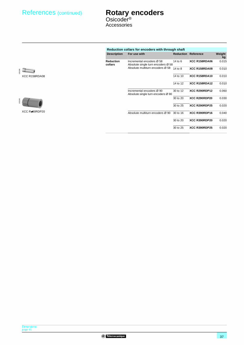
37
References (continued) 1 Rotary encoders 1
Osicoder®
Accessories
Reduction collars for encoders with through shaftDescription For use with Reduction Reference Weight
kgReduction collars
Incremental encoders Ø 58Absolute single turn encoders Ø 58Absolute multiturn encoders Ø 58
14 to 6 XCC R158RDA06 0.015
14 to 8 XCC R158RDA08 0.010
14 to 10 XCC R158RDA10 0.010
14 to 12 XCC R158RDA12 0.010
Incremental encoders Ø 90 Absolute single turn encoders Ø 90
30 to 12 XCC R290RDP12 0.060
30 to 20 XCC R290RDP20 0.030
30 to 25 XCC R290RDP25 0.020
Absolute multiturn encoders Ø 90 30 to 16 XCC R390RDP16 0.040
30 to 20 XCC R390RDP20 0.020
30 to 25 XCC R390RDP25 0.020
105
188
XCC R158RDA08
105
190
XCC Rp90RDP20
Dimensions:page 41
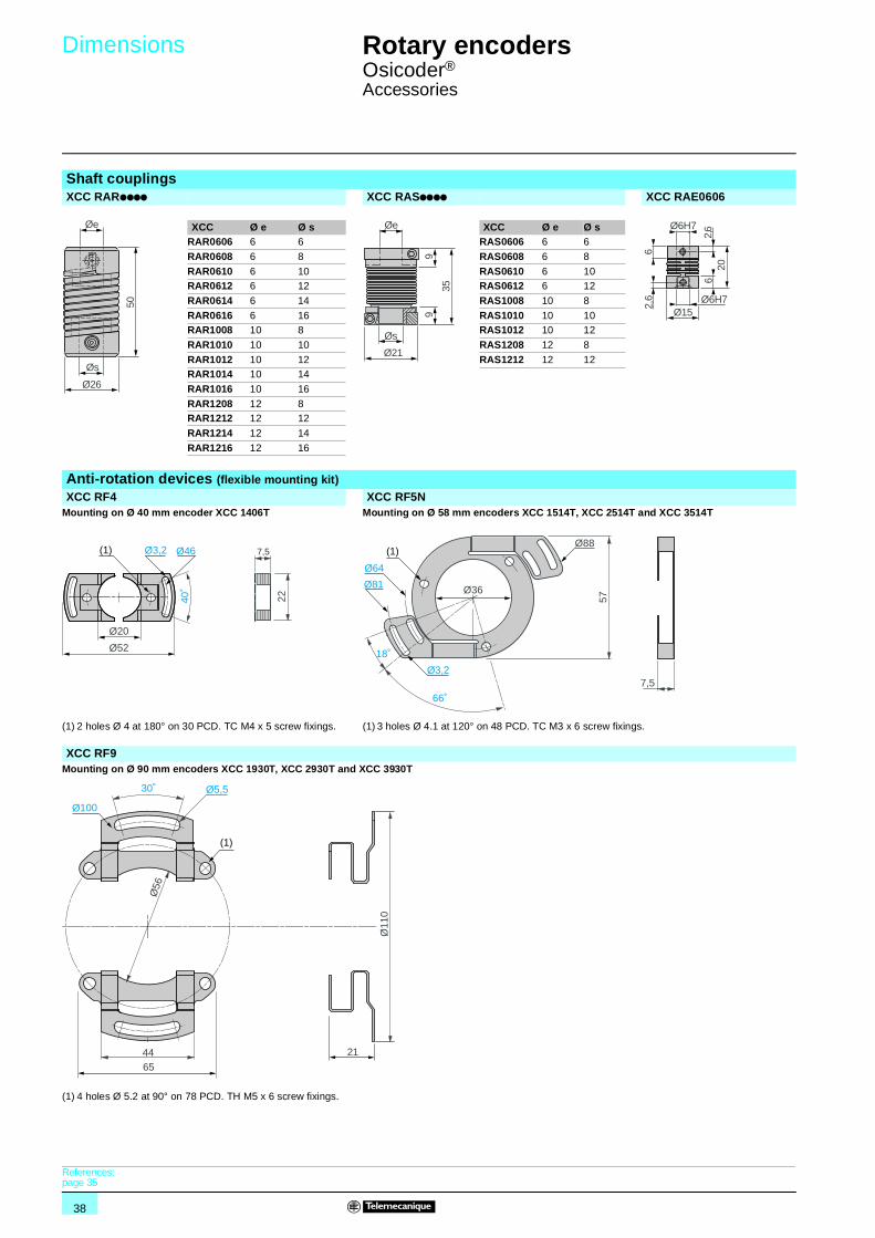
38
Dimensions 1 Rotary encoders 1
Osicoder®
Accessories
Shaft couplingsXCC RARpppp XCC RASpppp XCC RAE0606
XCC Ø e Ø s XCC Ø e Ø sRAR0606 6 6 RAS0606 6 6
RAR0608 6 8 RAS0608 6 8
RAR0610 6 10 RAS0610 6 10RAR0612 6 12 RAS0612 6 12
RAR0614 6 14 RAS1008 10 8
RAR0616 6 16 RAS1010 10 10RAR1008 10 8 RAS1012 10 12
RAR1010 10 10 RAS1208 12 8
RAR1012 10 12 RAS1212 12 12RAR1014 10 14
RAR1016 10 16
RAR1208 12 8RAR1212 12 12
RAR1214 12 14
RAR1216 12 16
Anti-rotation devices (flexible mounting kit)XCC RF4 XCC RF5N
Mounting on Ø 40 mm encoder XCC 1406T Mounting on Ø 58 mm encoders XCC 1514T, XCC 2514T and XCC 3514T
(1) 2 holes Ø 4 at 180° on 30 PCD. TC M4 x 5 screw fixings. (1) 3 holes Ø 4.1 at 120° on 48 PCD. TC M3 x 6 screw fixings.
XCC RF9Mounting on Ø 90 mm encoders XCC 1930T, XCC 2930T and XCC 3930T
(1) 4 holes Ø 5.2 at 90° on 78 PCD. TH M5 x 6 screw fixings.
50
Øe
Øs
Ø26
Øe
Øs
Ø21
35
99
Ø6H7
620
6
2,6
2,6
Ø6H7
Ø15
7,5
22
Ø52
Ø46
Ø20
40˚
(1) Ø3,2
Ø64
Ø88
Ø36Ø81
18˚
66˚
7,5
57
(1)
Ø3,2
30˚
Ø56
4465
21
(1)
Ø11
0
Ø100
Ø5,5
References:page 35
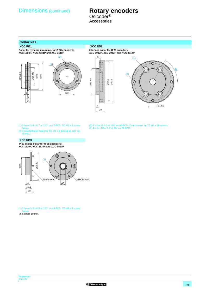
39
Dimensions (continued) 1 Rotary encoders 1
Osicoder®
Accessories
Collar kitsXCC RB1 XCC RB2
Collar for synchro mounting, for Ø 58 encoders: XCC 15ppP, XCC 25ppP and XXC 35ppP
Interface collar for Ø 90 encoders:XCC 1912P, XCC 2912P and XCC 3912P
(1) 3 holes M4 x 0.7 at 120° on 42 PCD. TC M3 x 8 screw fixings.
(2) 3 counterbored holes for TC M4 x 8 screws at 120° on 48 PCD.
(1) 4 holes Ø 6.6 at 120° on 60 PCD. Countersunk for TZ M6 x 16 screws.(2) 4 holes M5 x 0.8 at 90° on 78 PCD.
XCC RB3IP 67 sealed collar for Ø 58 encoders:XCC 1510P, XCC 2510P and XCC 3510P
(1) 3 holes M3 x 0.5 at 120° on 48 PCD. TZ M3 x 8 screw fixings.
(2) Shaft Ø 10 mm.
Ø58
Ø53
Ø32
Ø50
h9
Ø36
H8
4
10
3
(2)
(1)
Ø56
H9
Ø84
,5
Ø89
,5
Ø12,57
20
10
(2)
(1)
60˚
Ø36
f7
Ø58
10
13,5
18
(2)
(1)
Nitrile seal VITON seal
References:page 35
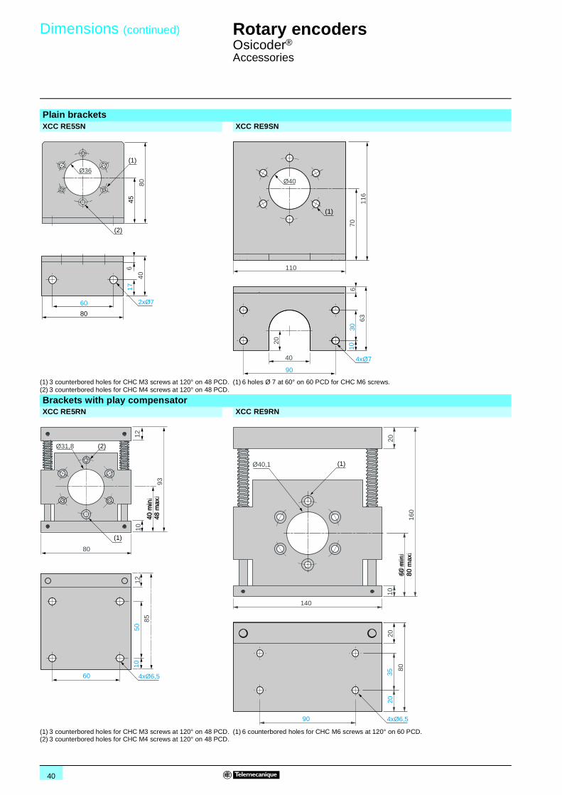
40
Dimensions (continued) 1 Rotary encoders 1
Osicoder®
Accessories
Plain bracketsXCC RE5SN XCC RE9SN
(1) 3 counterbored holes for CHC M3 screws at 120° on 48 PCD.(2) 3 counterbored holes for CHC M4 screws at 120° on 48 PCD.
(1) 6 holes Ø 7 at 60° on 60 PCD for CHC M6 screws.
Brackets with play compensatorXCC RE5RN XCC RE9RN
(1) 3 counterbored holes for CHC M3 screws at 120° on 48 PCD.(2) 3 counterbored holes for CHC M4 screws at 120° on 48 PCD.
(1) 6 counterbored holes for CHC M6 screws at 120° on 60 PCD.
Ø36
80
45
80
2xØ7
617
40
(1)
(2)
60
30
20
90
110
10
Ø40
670
116
63
(1)
4xØ740
50
60
80
1012
10
93
40 m
ini
48 m
axi
Ø31,8
8512
4xØ6,5
(1)
(2)
40 m
in.
48 m
ax.
3520
1020
90
140
80
160
60 m
ini
80 m
axi
(1)
4xØ6,5
20
Ø40,1
60
min
.8
0 m
ax.
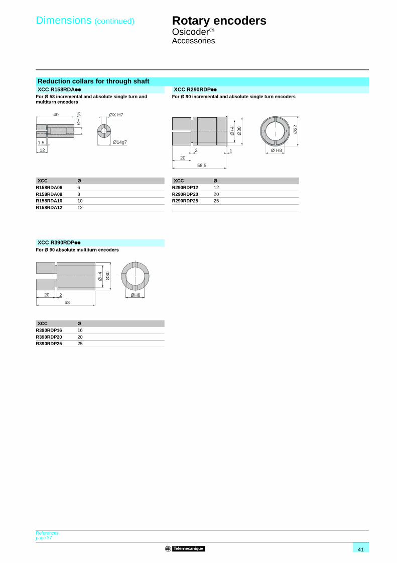
41
Dimensions (continued) 1 Rotary encoders 1
Osicoder®
Accessories
Reduction collars for through shaftXCC R158RDApp XCC R290RDPpp
For Ø 58 incremental and absolute single turn and multiturn encoders
For Ø 90 incremental and absolute single turn encoders
XCC Ø XCC ØR158RDA06 6 R290RDP12 12
R158RDA08 8 R290RDP20 20R158RDA10 10 R290RDP25 25
R158RDA12 12
XCC R390RDPppFor Ø 90 absolute multiturn encoders
XCC ØR390RDP16 16
R390RDP20 20R390RDP25 25
Ø14g7
40
12
1,5
ØX H7
Ø+
2,5
Ø30
Ø+
4
58,5
1
20
2 Ø H8
Ø32
Ø+
4
63
20
Ø30
2 ØH8
References:page 37
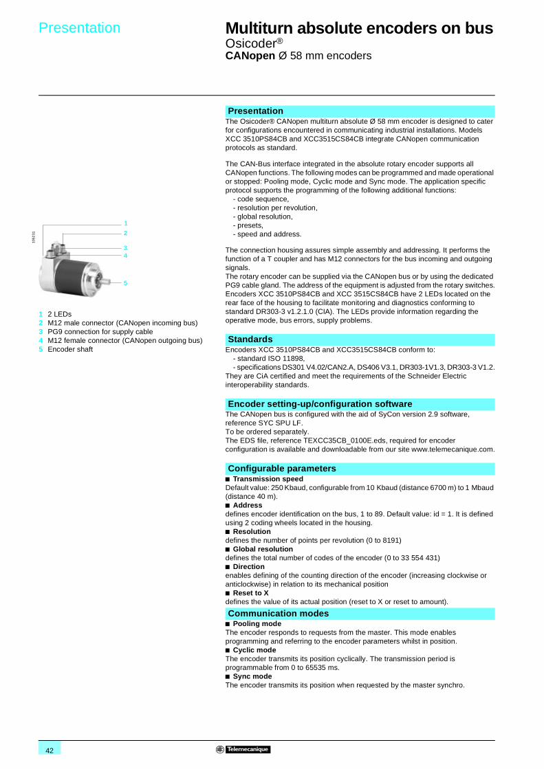
42
Presentation 1 Multiturn absolute encoders on bus1
Osicoder®
CANopen Ø 58 mm encoders
The Osicoder® CANopen multiturn absolute Ø 58 mm encoder is designed to cater for configurations encountered in communicating industrial installations. Models XCC 3510PS84CB and XCC3515CS84CB integrate CANopen communication protocols as standard.
The CAN-Bus interface integrated in the absolute rotary encoder supports all CANopen functions. The following modes can be programmed and made operational or stopped: Pooling mode, Cyclic mode and Sync mode. The application specific protocol supports the programming of the following additional functions:
- code sequence,- resolution per revolution,- global resolution,- presets,- speed and address.
The connection housing assures simple assembly and addressing. It performs the function of a T coupler and has M12 connectors for the bus incoming and outgoing signals. The rotary encoder can be supplied via the CANopen bus or by using the dedicated PG9 cable gland. The address of the equipment is adjusted from the rotary switches.Encoders XCC 3510PS84CB and XCC 3515CS84CB have 2 LEDs located on the rear face of the housing to facilitate monitoring and diagnostics conforming to standard DR303-3 v1.2.1.0 (CIA). The LEDs provide information regarding the operative mode, bus errors, supply problems.
Encoders XCC 3510PS84CB and XCC3515CS84CB conform to:- standard ISO 11898,- specifications DS301 V4.02/CAN2.A, DS406 V3.1, DR303-1V1.3, DR303-3 V1.2.
They are CiA certified and meet the requirements of the Schneider Electric interoperability standards.
The CANopen bus is configured with the aid of SyCon version 2.9 software, reference SYC SPU LF. To be ordered separately.The EDS file, reference TEXCC35CB_0100E.eds, required for encoder configuration is available and downloadable from our site www.telemecanique.com.
b Transmission speedDefault value: 250 Kbaud, configurable from 10 Kbaud (distance 6700 m) to 1 Mbaud (distance 40 m).b Address defines encoder identification on the bus, 1 to 89. Default value: id = 1. It is defined using 2 coding wheels located in the housing.b Resolution defines the number of points per revolution (0 to 8191)b Global resolution defines the total number of codes of the encoder (0 to 33 554 431)b Direction enables defining of the counting direction of the encoder (increasing clockwise or anticlockwise) in relation to its mechanical positionb Reset to X defines the value of its actual position (reset to X or reset to amount).
b Pooling mode The encoder responds to requests from the master. This mode enables programming and referring to the encoder parameters whilst in position.b Cyclic mode The encoder transmits its position cyclically. The transmission period is programmable from 0 to 65535 ms.b Sync mode The encoder transmits its position when requested by the master synchro.
Presentation
2
34
5
1 2 LEDs2 M12 male connector (CANopen incoming bus)3 PG9 connection for supply cable4 M12 female connector (CANopen outgoing bus)5 Encoder shaft
1052
31
1
Standards
Encoder setting-up/configuration software
Configurable parameters
Communication modes
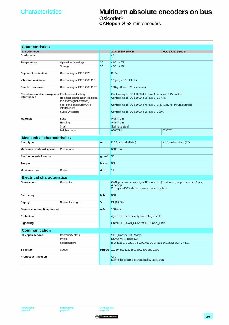
43
Characteristics 1 Multiturn absolute encoders on bus1
Osicoder®
CANopen Ø 58 mm encoders
CharacteristicsEncoder type XCC 3510PS84CB XCC 3515CS84CB
Conformity e
Temperature Operation (housing) °C - 40…+ 85
Storage °C - 40…+ 85
Degree of protection Conforming to IEC 60529 IP 64
Vibration resistance Conforming to IEC 60068-2-6 10 gn (f = 10…2 kHz)
Shock resistance Conforming to IEC 60068-2-27 100 gn (6 ms, 1/2 sine wave)
Resistance to electromagnetic interference
Electrostatic discharges Conforming to IEC 61000-4-2: level 2, 4 kV air; 2 kV contactRadiated electromagnetic fields (electromagnetic waves)
Conforming to IEC 61000-4-3: level 3, 10 V/m
Fast transients (Start/Stop interference)
Conforming to IEC 61000-4-4: level 3, 2 kV (1 kV for inputs/outputs)
Surge withstand Conforming to IEC 61000-4-5: level 1, 500 V
Materials Base Aluminium
Housing Aluminium
Shaft Stainless steelBall bearings 6000ZZ1 6803ZZ
Mechanical characteristicsShaft type mm Ø 10, solid shaft (h8) Ø 15, hollow shaft (F7)
Maximum rotational speed Continuous 6000 rpm
Shaft moment of inertia g.cm2 30
Torque N.cm 0.3
Maximum load Radial daN 11
Electrical characteristicsConnection Connector CANopen bus network by M12 connector (input: male; output: female), 5-pin,
A coding.Supply via PG9 of each encoder or via the bus
Frequency kHz 800
Supply Nominal voltage V 24 (10-30)
Current consumption, no-load mA 100 max.
Protection Against reverse polarity and voltage peaks
Signalling Green LED: CAN_RUN; red LED: CAN_ERR
CommunicationCANopen service Conformity class S10 (Transparent Ready)
Profile DS406 V3.1, class C2
Specifications ISO 11898, DS301 V4.02/CAN2.A, DR303-1V1.3, DR303-3 V1.2.
Structure Speed Kbps/s 10, 20, 50, 125, 250, 500, 800 and 1000
Product certification CiA Schneider Electric interoperability standards
References:page 44
Dimensions:page 45
Connections:page 45
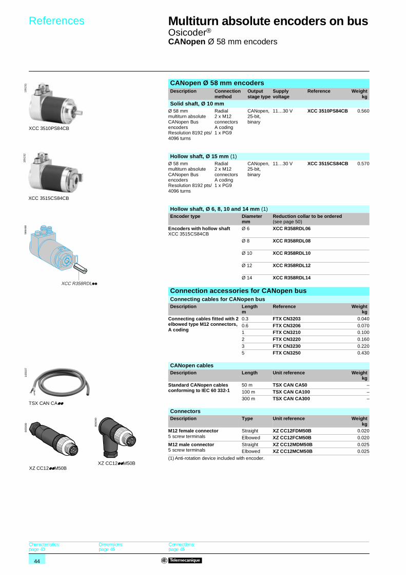
44
References 1 Multiturn absolute encoders on bus1
Osicoder®
CANopen Ø 58 mm encoders
CANopen Ø 58 mm encodersDescription Connection
methodOutput stage type
Supply voltage
Reference Weightkg
Solid shaft, Ø 10 mmØ 58 mm multiturn absolute CANopen Bus encodersResolution 8192 pts/4096 turns
Radial2 x M12 connectors A coding 1 x PG9
CANopen, 25-bit, binary
11…30 V XCC 3510PS84CB 0.560
Hollow shaft, Ø 15 mm (1)Ø 58 mm multiturn absolute CANopen Bus encodersResolution 8192 pts/4096 turns
Radial2 x M12 connectors A coding 1 x PG9
CANopen, 25-bit, binary
11…30 V XCC 3515CS84CB 0.570
Hollow shaft, Ø 6, 8, 10 and 14 mm (1)Encoder type Diameter
mmReduction collar to be ordered (see page 50)
Encoders with hollow shaft XCC 3515CS84CB
Ø 6 XCC R358RDL06
Ø 8 XCC R358RDL08
Ø 10 XCC R358RDL10
Ø 12 XCC R358RDL12
Ø 14 XCC R358RDL14
Connection accessories for CANopen busConnecting cables for CANopen busDescription Length
mReference Weight
kgConnecting cables fitted with 2 elbowed type M12 connectors, A coding
0.3 FTX CN3203 0.040
0.6 FTX CN3206 0.0701 FTX CN3210 0.100
2 FTX CN3220 0.160
3 FTX CN3230 0.2205 FTX CN3250 0.430
CANopen cablesDescription Length Unit reference Weight
kgStandard CANopen cables conforming to IEC 60 332-1
50 m TSX CAN CA50 –
100 m TSX CAN CA100 –300 m TSX CAN CA300 –
ConnectorsDescription Type Unit reference Weight
kgM12 female connector5 screw terminals
Straight XZ CC12FDM50B 0.020
Elbowed XZ CC12FCM50B 0.020
M12 male connector5 screw terminals
Straight XZ CC12MDM50B 0.025Elbowed XZ CC12MCM50B 0.025
(1) Anti-rotation device included with encoder.
105
231
XCC 3510PS84CB
XCC 3515CS84CB
105
232
XCC R358RDL
5664
681
055
07
TSX CAN CApp
XZ CC12ppM50B
805
999
XZ CC12ppM50B
8060
00
Characteristics:page 43
Dimensions:page 45
Connections:page 45
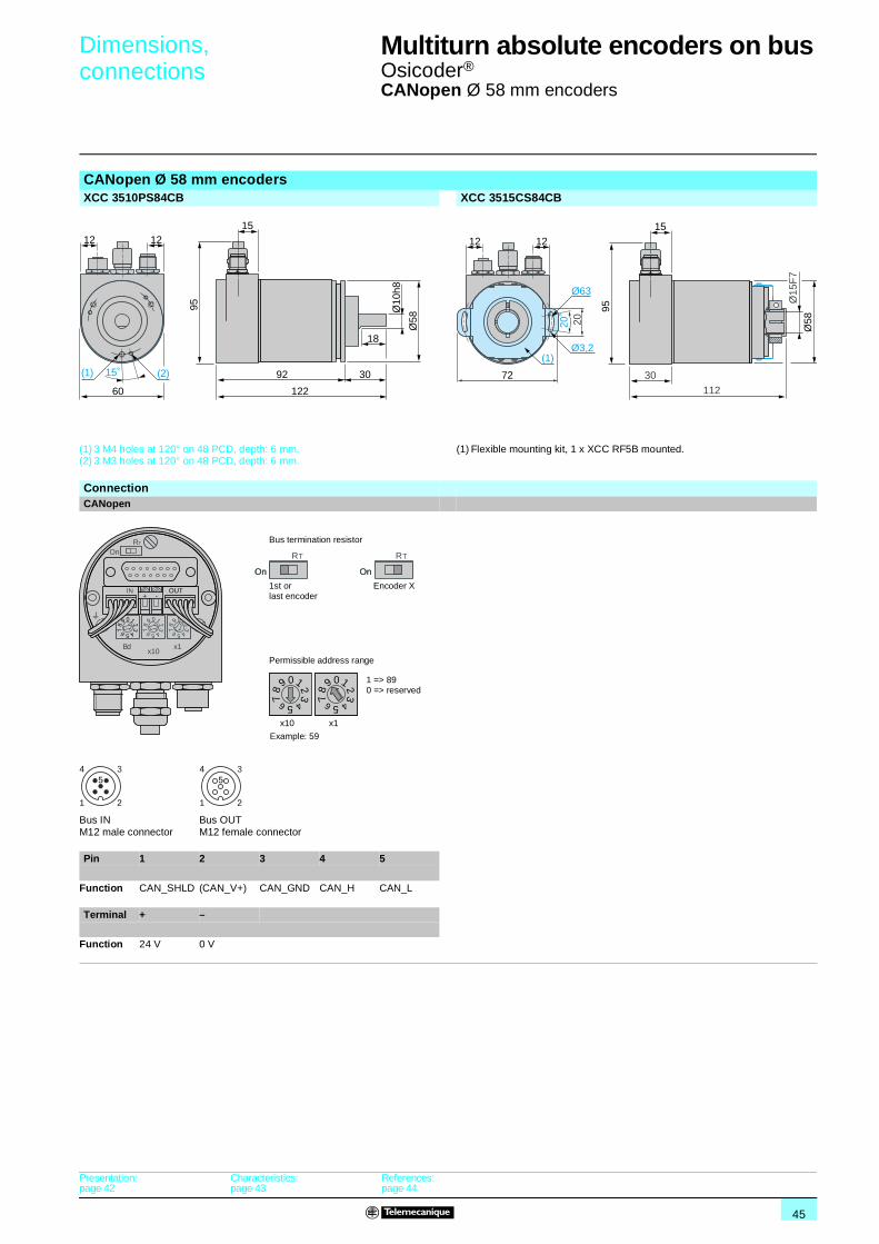
45
Dimensions,connections 1
Multiturn absolute encoders on bus1
Osicoder®
CANopen Ø 58 mm encoders
CANopen Ø 58 mm encodersXCC 3510PS84CB XCC 3515CS84CB
(1) 3 M4 holes at 120° on 48 PCD, depth: 6 mm.(2) 3 M3 holes at 120° on 48 PCD, depth: 6 mm.
(1) Flexible mounting kit, 1 x XCC RF5B mounted.
ConnectionCANopen
Bus INM12 male connector
Bus OUTM12 female connector
Pin 1 2 3 4 5
Function CAN_SHLD (CAN_V+) CAN_GND CAN_H CAN_L
Terminal + –
Function 24 V 0 V
15˚ 92 30
18
Ø10
h8
Ø58
60 122
(2)(1)
1512 12
95 95
Ø58
112
30
Ø15
F7
20˚
72
Ø63
20
Ø3,2(1)
12 1215
On On
x1x10
09
87 6 54
321 09
87 6 54
321
TR TR
On On
09
87 6 54
321 09
87 6 54
321
RT
Bd x1x10
On
-+
09
87 6 54
32109
87 6 54
321 09
87 6 54
321
OUTIN
Bus termination resistor
1st or last encoder
Encoder X
Permissible address range
Example: 59
1 => 890 => reserved
1 2
4 35
1 2
4 35
Presentation:page 42
Characteristics:page 43
References:page 44
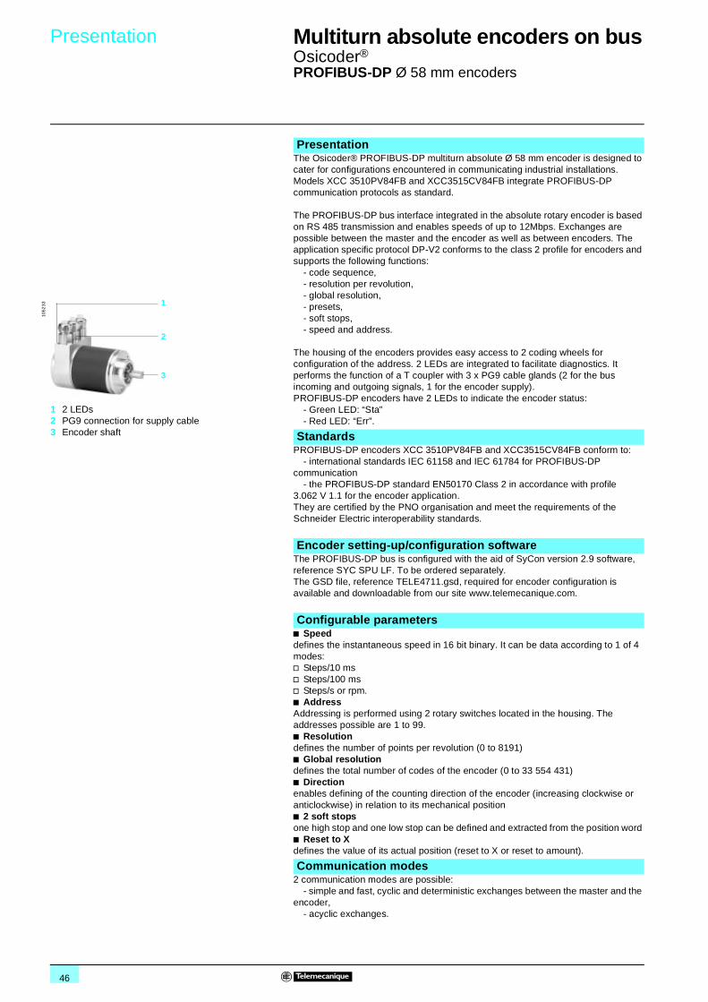
46
Presentation 1 Multiturn absolute encoders on bus1
Osicoder®
PROFIBUS-DP Ø 58 mm encoders
The Osicoder® PROFIBUS-DP multiturn absolute Ø 58 mm encoder is designed to cater for configurations encountered in communicating industrial installations. Models XCC 3510PV84FB and XCC3515CV84FB integrate PROFIBUS-DP communication protocols as standard.
The PROFIBUS-DP bus interface integrated in the absolute rotary encoder is based on RS 485 transmission and enables speeds of up to 12Mbps. Exchanges are possible between the master and the encoder as well as between encoders. The application specific protocol DP-V2 conforms to the class 2 profile for encoders and supports the following functions:
- code sequence,- resolution per revolution,- global resolution,- presets,- soft stops, - speed and address.
The housing of the encoders provides easy access to 2 coding wheels for configuration of the address. 2 LEDs are integrated to facilitate diagnostics. It performs the function of a T coupler with 3 x PG9 cable glands (2 for the bus incoming and outgoing signals, 1 for the encoder supply). PROFIBUS-DP encoders have 2 LEDs to indicate the encoder status:
- Green LED: “Sta”- Red LED: “Err”.
PROFIBUS-DP encoders XCC 3510PV84FB and XCC3515CV84FB conform to: - international standards IEC 61158 and IEC 61784 for PROFIBUS-DP
communication- the PROFIBUS-DP standard EN50170 Class 2 in accordance with profile
3.062 V 1.1 for the encoder application.They are certified by the PNO organisation and meet the requirements of the Schneider Electric interoperability standards.
The PROFIBUS-DP bus is configured with the aid of SyCon version 2.9 software, reference SYC SPU LF. To be ordered separately.The GSD file, reference TELE4711.gsd, required for encoder configuration is available and downloadable from our site www.telemecanique.com.
b Speeddefines the instantaneous speed in 16 bit binary. It can be data according to 1 of 4 modes:v Steps/10 msv Steps/100 msv Steps/s or rpm.b Address Addressing is performed using 2 rotary switches located in the housing. The addresses possible are 1 to 99.b Resolutiondefines the number of points per revolution (0 to 8191)b Global resolutiondefines the total number of codes of the encoder (0 to 33 554 431)b Directionenables defining of the counting direction of the encoder (increasing clockwise or anticlockwise) in relation to its mechanical positionb 2 soft stops one high stop and one low stop can be defined and extracted from the position word b Reset to Xdefines the value of its actual position (reset to X or reset to amount).
2 communication modes are possible:- simple and fast, cyclic and deterministic exchanges between the master and the
encoder, - acyclic exchanges.
Presentation
1
2
3
1 2 LEDs2 PG9 connection for supply cable3 Encoder shaft
1052
33
Standards
Encoder setting-up/configuration software
Configurable parameters
Communication modes
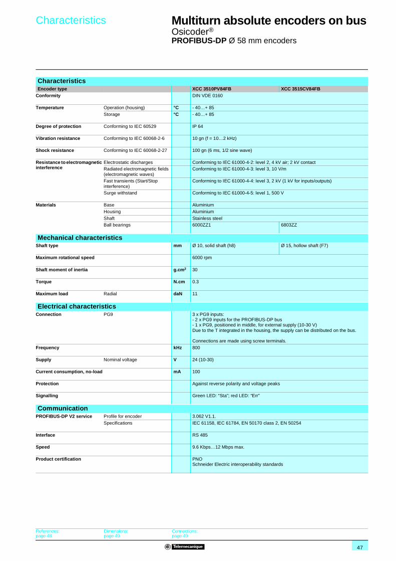
47
Characteristics 1 Multiturn absolute encoders on bus1
Osicoder®
PROFIBUS-DP Ø 58 mm encoders
CharacteristicsEncoder type XCC 3510PV84FB XCC 3515CV84FB
Conformity DIN VDE 0160
Temperature Operation (housing) °C - 40…+ 85
Storage °C - 40…+ 85
Degree of protection Conforming to IEC 60529 IP 64
Vibration resistance Conforming to IEC 60068-2-6 10 gn (f = 10…2 kHz)
Shock resistance Conforming to IEC 60068-2-27 100 gn (6 ms, 1/2 sine wave)
Resistance to electromagnetic interference
Electrostatic discharges Conforming to IEC 61000-4-2: level 2, 4 kV air; 2 kV contactRadiated electromagnetic fields (electromagnetic waves)
Conforming to IEC 61000-4-3: level 3, 10 V/m
Fast transients (Start/Stop interference)
Conforming to IEC 61000-4-4: level 3, 2 kV (1 kV for inputs/outputs)
Surge withstand Conforming to IEC 61000-4-5: level 1, 500 V
Materials Base Aluminium
Housing Aluminium
Shaft Stainless steelBall bearings 6000ZZ1 6803ZZ
Mechanical characteristicsShaft type mm Ø 10, solid shaft (h8) Ø 15, hollow shaft (F7)
Maximum rotational speed 6000 rpm
Shaft moment of inertia g.cm2 30
Torque N.cm 0.3
Maximum load Radial daN 11
Electrical characteristicsConnection PG9 3 x PG9 inputs:
- 2 x PG9 inputs for the PROFIBUS-DP bus- 1 x PG9, positioned in middle, for external supply (10-30 V)Due to the T integrated in the housing, the supply can be distributed on the bus. Connections are made using screw terminals.
Frequency kHz 800
Supply Nominal voltage V 24 (10-30)
Current consumption, no-load mA 100
Protection Against reverse polarity and voltage peaks
Signalling Green LED: “Sta”; red LED: “Err”
CommunicationPROFIBUS-DP V2 service Profile for encoder 3.062 V1.1.
Specifications IEC 61158, IEC 61784, EN 50170 class 2, EN 50254
Interface RS 485
Speed 9.6 Kbps…12 Mbps max.
Product certification PNOSchneider Electric interoperability standards
References:page 48
Dimensions:page 49
Connections:page 49
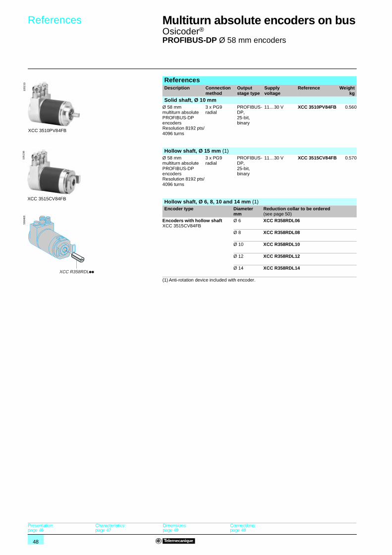
48
References 1 Multiturn absolute encoders on bus1
Osicoder®
PROFIBUS-DP Ø 58 mm encoders
ReferencesDescription Connection
methodOutput stage type
Supply voltage
Reference Weightkg
Solid shaft, Ø 10 mmØ 58 mm multiturn absolute PROFIBUS-DP encodersResolution 8192 pts/4096 turns
3 x PG9 radial
PROFIBUS-DP, 25-bit, binary
11…30 V XCC 3510PV84FB 0.560
Hollow shaft, Ø 15 mm (1)Ø 58 mm multiturn absolute PROFIBUS-DP encodersResolution 8192 pts/4096 turns
3 x PG9 radial
PROFIBUS-DP, 25-bit, binary
11…30 V XCC 3515CV84FB 0.570
Hollow shaft, Ø 6, 8, 10 and 14 mm (1)Encoder type Diameter
mmReduction collar to be ordered (see page 50)
Encoders with hollow shaft XCC 3515CV84FB
Ø 6 XCC R358RDL06
Ø 8 XCC R358RDL08
Ø 10 XCC R358RDL10
Ø 12 XCC R358RDL12
Ø 14 XCC R358RDL14
(1) Anti-rotation device included with encoder.
XCC 3510PV84FB
1052
33
XCC 3515CV84FB
105
236
566
468
XCC R358RDL
Presentation:page 46
Characteristics:page 47
Dimensions:page 49
Connections:page 49
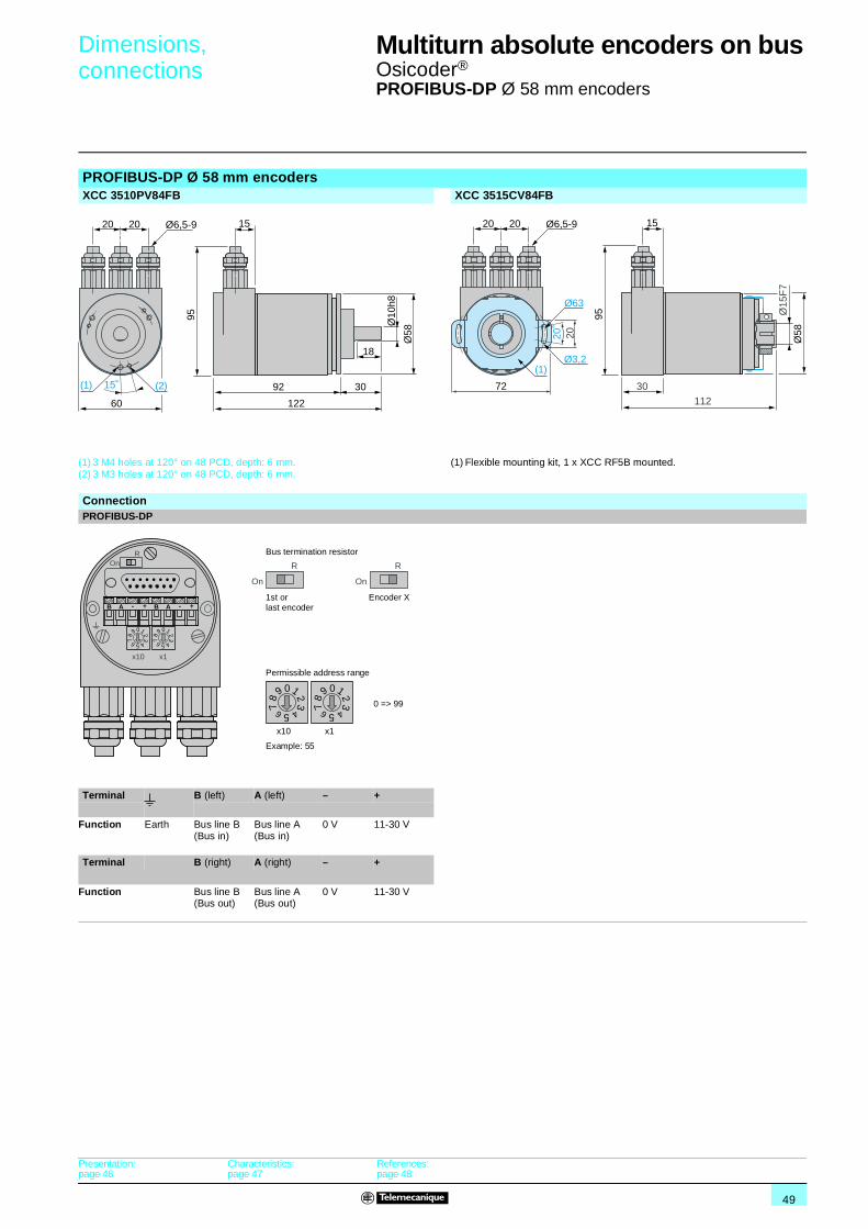
49
Dimensions,connections 1
Multiturn absolute encoders on bus1
Osicoder®
PROFIBUS-DP Ø 58 mm encoders
PROFIBUS-DP Ø 58 mm encodersXCC 3510PV84FB XCC 3515CV84FB
(1) 3 M4 holes at 120° on 48 PCD, depth: 6 mm.(2) 3 M3 holes at 120° on 48 PCD, depth: 6 mm.
(1) Flexible mounting kit, 1 x XCC RF5B mounted.
ConnectionPROFIBUS-DP
Terminal B (left) A (left) – +
Function Earth Bus line B(Bus in)
Bus line A(Bus in)
0 V 11-30 V
Terminal B (right) A (right) – +
Function Bus line B(Bus out)
Bus line A(Bus out)
0 V 11-30 V
15˚
Ø6,5-920 20 15
92 30
18
Ø10
h8
Ø58
95
60 122
(2)(1)
20˚
72
Ø58
15
95
Ø63
112
30
20
Ø3,2
Ø15
F7
(1)
Ø6,5-920 20
R
x1x10
On
AB AB- + - +
09
87 6 54
321 09
87 6 54
321
R
On
R
On
0 => 99
x1x10
09
87 6 54
321 09
87 6 54
321
Bus termination resistor
1st or last encoder
Encoder X
Permissible address range
Example: 55
Presentation: page 46
Characteristics: page 47
References: page 48
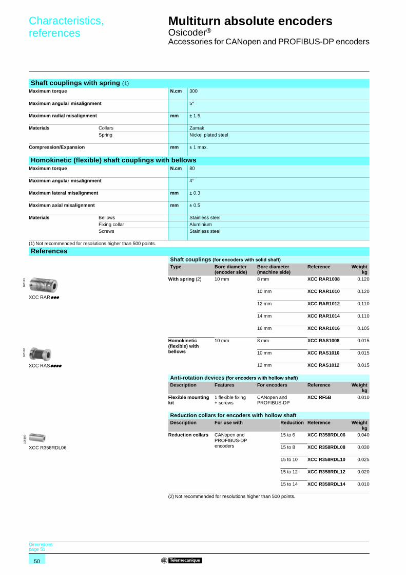
50
Characteristics, references 1
Multiturn absolute encoders 1
Osicoder®
Accessories for CANopen and PROFIBUS-DP encoders
Shaft couplings with spring (1)Maximum torque N.cm 300
Maximum angular misalignment 5°
Maximum radial misalignment mm ± 1.5
Materials Collars Zamak
Spring Nickel plated steel
Compression/Expansion mm ± 1 max.
Homokinetic (flexible) shaft couplings with bellowsMaximum torque N.cm 80
Maximum angular misalignment 4°
Maximum lateral misalignment mm ± 0.3
Maximum axial misalignment mm ± 0.5
Materials Bellows Stainless steel
Fixing collar AluminiumScrews Stainless steel
(1) Not recommended for resolutions higher than 500 points.
ReferencesShaft couplings (for encoders with solid shaft)Type Bore diameter
(encoder side)Bore diameter (machine side)
Reference Weightkg
With spring (2) 10 mm 8 mm XCC RAR1008 0.120
10 mm XCC RAR1010 0.120
12 mm XCC RAR1012 0.110
14 mm XCC RAR1014 0.110
16 mm XCC RAR1016 0.105
Homokinetic (flexible) with bellows
10 mm 8 mm XCC RAS1008 0.015
10 mm XCC RAS1010 0.015
12 mm XCC RAS1012 0.015
Anti-rotation devices (for encoders with hollow shaft)Description Features For encoders Reference Weight
kgFlexible mounting kit
1 flexible fixing + screws
CANopen and PROFIBUS-DP
XCC RF5B 0.010
Reduction collars for encoders with hollow shaftDescription For use with Reduction Reference Weight
kgReduction collars CANopen and
PROFIBUS-DP encoders
15 to 6 XCC R358RDL06 0.040
15 to 8 XCC R358RDL08 0.030
15 to 10 XCC R358RDL10 0.025
15 to 12 XCC R358RDL12 0.020
15 to 14 XCC R358RDL14 0.010
(2) Not recommended for resolutions higher than 500 points.
105
191
XCC RARppp
1051
92
XCC RASpppp
105
189
XCC R358RDL06
Dimensions:page 51
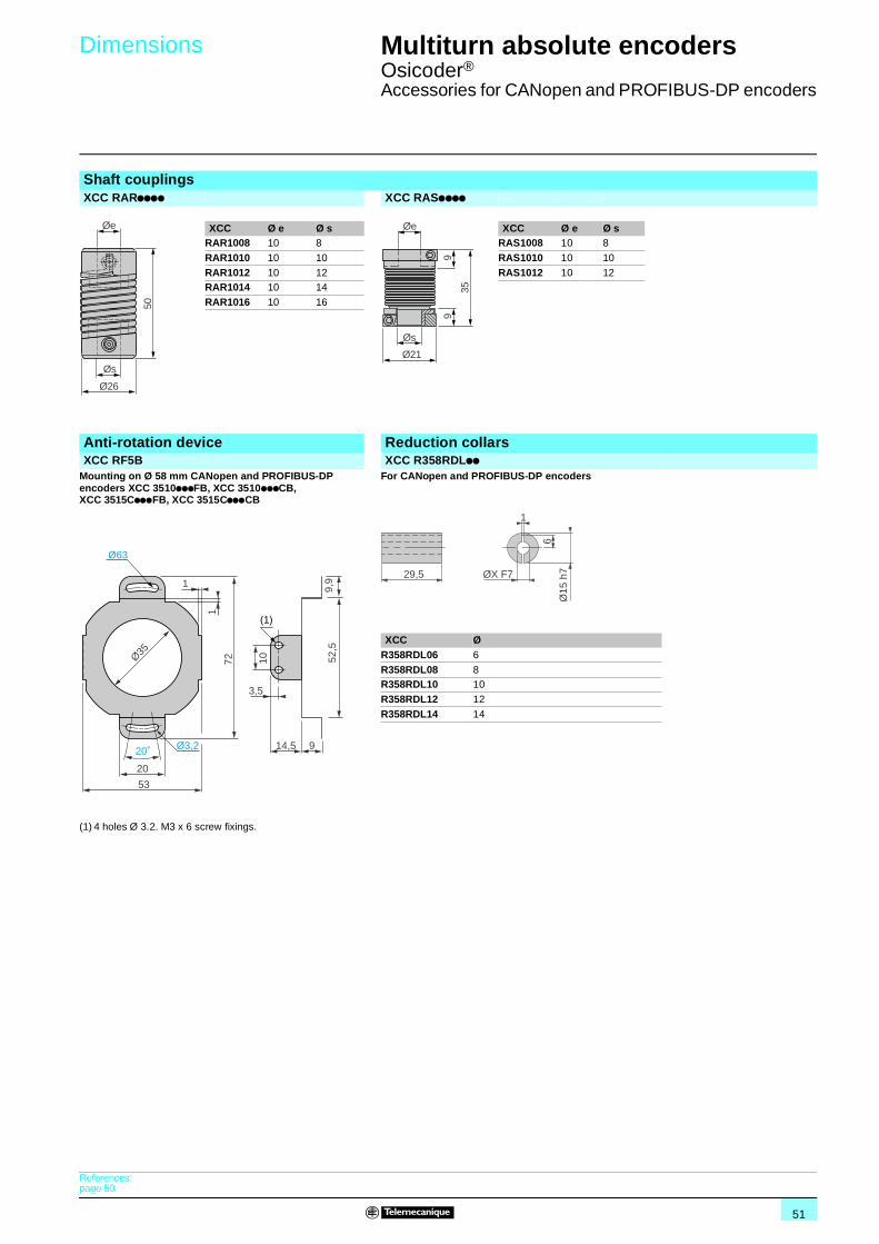
51
Dimensions 1 Multiturn absolute encoders 1
Osicoder®
Accessories for CANopen and PROFIBUS-DP encoders
Shaft couplingsXCC RARpppp XCC RASpppp
XCC Ø e Ø s XCC Ø e Ø sRAR1008 10 8 RAS1008 10 8
RAR1010 10 10 RAS1010 10 10
RAR1012 10 12 RAS1012 10 12RAR1014 10 14
RAR1016 10 16
Anti-rotation device Reduction collarsXCC RF5B XCC R358RDLpp
Mounting on Ø 58 mm CANopen and PROFIBUS-DP encoders XCC 3510pppFB, XCC 3510pppCB, XCC 3515CpppFB, XCC 3515CpppCB
For CANopen and PROFIBUS-DP encoders
XCC ØR358RDL06 6
R358RDL08 8R358RDL10 10
R358RDL12 12
R358RDL14 14
(1) 4 holes Ø 3.2. M3 x 6 screw fixings.
50
Øe
Øs
Ø26
Øe
Øs
Ø21
35
99
Ø63
72 52,5
1
1
10
20
914,5
3,5
Ø3,220˚
9,9
Ø35
53
(1)
Ø15
h729,5 ØX F7
6
1
References:page 50

ART. 808623 01 / 2006
DIA
4ED
2051
202E
N
Schneider Electric Industries SAS
Head Office89, bd Franklin Roosevelt92506 Rueil-Malmaison CedexFrance
www.schneider-electric.comwww.telemecanique.com
Due to evolution of standards and equipment, the characteristics indicated in texts and images of thisdocument do not constitute a commitment on our part without confirmation.Design: Schneider ElectricPhotos: Schneider ElectricPrinted by:
Simply Smart !
The efficiency of Telemecanique branded solutionsUsed in combination, Telemecanique products provide quality solutions, meeting all your Automation & Control applications requirements.
A worldwide presence
Constantly availableb More than 5 000 points of sale in 130 countries.b You can be sure to find the range of products that are right for you and which complies fully with the standards in the country where they are used.
Technical assistance wherever you areb Our technicians are at your disposal to assist you in finding the optimum solution for your particular needs.b Schneider Electric provides you with all necessary technical assistance, throughout the world.