oscoda - facility requirements (v6.0) - home - oscoda airport · runway length is determined from...
TRANSCRIPT
CHAPTER 3
FACILITY REQUIREMENTS

Oscoda – Wurtsmith Airport Authority Oscoda-Wurtsmith Airport Master Plan
Facility Requirements 3-1 Final Document
CHAPTER 3 FACILITY REQUIREMENTS
This chapter identifies the Airport facilities necessary to satisfy the 20-year aviation demands at the Oscoda-Wurtsmith Airport. Facility needs are identified for the purpose of resolving existing deficiencies, accommodating forecast activity levels, and satisfying the strategic goals as envisioned by the Oscoda-Wurtsmith Airport Authority for long-term development of the Airport. The following are the key facilities documented in this chapter:
• Airport Facility Design Standards
• Runway and Taxiway System
• Aviation Support Facilities
• Airspace and Navigational Aids
• Aeronautical and Non-Aeronautical Terminal Area Facilities and Access
• Landside/Tenant Area Facilities
The facility improvements are planned in accordance with Federal Aviation Administration (FAA) and Michigan DOT–Aeronautics (MDOT) design standards, as necessary to meet the mission of the Airport. It should be noted that the facility recommendations are not absolute design requirements, but rather options to resolve various types of facility and operational inadequacies, or to make improvements as demand warrants and funding becomes available. Therefore, extenuating circumstances do sometimes require project or scheduling adjustments to meet unforeseen user demand and/or unanticipated facility needs.
3.1 AIRPORT PLANNING & DESIGN STANDARDS
3.1.1 Airport Strategic Vision
The Airport Authority’s strategic vision clearly seeks to offer airfield facilities suited to support specialized aviation maintenance-related tenants performing aircraft and engine repairs on heavy wide-body transport aircraft. To meet this strategic vision, it is essential to provide the runway and taxiway system capable of accommodating the Boeing 747 critical aircraft, including prospects of more frequent B-747 operations and even occasional larger transport aircraft traffic at Oscoda in the future. 3.1.2 Airport Planning Role
For planning purposes, the FAA designates the Oscoda-Wurtsmith Airport as a ‘General Aviation’ facility, for which the Airport Layout Plan (ALP) must adhere to ARC D-V design standards as defined by FAA Advisory Circular 150/5300-13, Airport Design. MDOT identifies the Airport in the Michigan Airport System Plan (MASP) as a Tier I General Aviation facility. The existing and future Airport role, classification and service level are substantiated by the Forecast Chapter.

Oscoda – Wurtsmith Airport Authority Oscoda-Wurtsmith Airport Master Plan
Facility Requirements 3-2 Final Document
3.1.3 FAA Design Standards - Airport Reference Code (ARC) Classification
The planning of airport facilities conforms to FAA design standards, as pertaining to the operational and physical characteristics of the ‘critical aircraft’, or representative of the largest aircraft conducting more than 500 annual itinerant operations (takeoffs and landings) at the Airport. The critical aircraft is evaluated with respect to size, speed and weight, and is the basis for determining the airfield and terminal area standards for various structural dimensions, setback separations, airspace clearances, safety areas and other design considerations. Combined, the 'approach category' (alphabetic letter) and 'design group' (roman numeral) yields the Airport Reference Code (ARC) which determines the type of airplane (family) that the airport is designed to accommodate. Table 3-1 shows the ARC design attributes for the D-V category aircraft. As substantiated by the
Forecast Chapter, the existing and future Airport Reference Code (ARC) for the Oscoda-Wurtsmith Airport is D-V, as represented by the Boeing-747-200/400 wide-body critical aircraft. Therefore, the Airport (airfield) design standards need to accommodate aircraft with an approach speed less than 166 knots and an aircraft wingspan of up to 214 feet.
Table 3-1 FAA AIRPORT REFERENCE CODE (ARC)
OSCODA CRITICAL AIRCRAFT – BOEING 747 (CATEGORY D-V)
The Boeing-747 (ARC D-V) operates between 400 and 500 annual operations at the Oscoda-Wurtsmith Airport, resulting from Kalitta aircraft maintenance and repair functions
Source: Airport Photos
Existing / Future ARC Approach Category
Category A
Category B
Category C
Existing/Future ARC --> Category D
Category E
Existing / Future ARC Design Group Wingspan (ft) Tail Height (ft)
Group I < 49' < 20
Group II 49' to < 79' 20' to < 30'
Group III 70' to < 118' 30' to < 45'
Group IV 118' to < 171' 45' to < 60'
Existing/Future ARC --> Group V 171' to < 214' 60' to < 66'
Group VI 214' to < 262' 66' to < 80'
Source: FAA Advisory Circular 150/5300-13.
Combined, the 'Approach Category' and 'Design Group' yields the Airport Reference Code (ARC) which
determines the type of airplane the airport is designed to accommodate.
Approach Speed (knots)
< 91 knots
91 to < 121 knots
121 to < 141 knots
141 to < 166 knots
> 166 knots
Oscoda – Wurtsmith Airport Authority Oscoda-Wurtsmith Airport Master Plan
Facility Requirements 3-3 Final Document
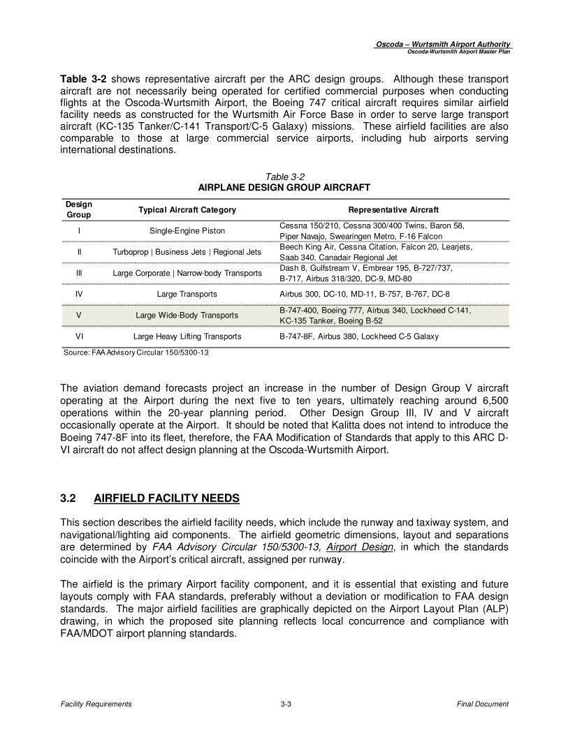
Table 3-2 shows representative aircraft per the ARC design groups. Although these transport aircraft are not necessarily being operated for certified commercial purposes when conducting flights at the Oscoda-Wurtsmith Airport, the Boeing 747 critical aircraft requires similar airfield facility needs as constructed for the Wurtsmith Air Force Base in order to serve large transport aircraft (KC-135 Tanker/C-141 Transport/C-5 Galaxy) missions. These airfield facilities are also comparable to those at large commercial service airports, including hub airports serving international destinations.
Table 3-2 AIRPLANE DESIGN GROUP AIRCRAFT
The aviation demand forecasts project an increase in the number of Design Group V aircraft operating at the Airport during the next five to ten years, ultimately reaching around 6,500 operations within the 20-year planning period. Other Design Group III, IV and V aircraft occasionally operate at the Airport. It should be noted that Kalitta does not intend to introduce the Boeing 747-8F into its fleet, therefore, the FAA Modification of Standards that apply to this ARC D-VI aircraft do not affect design planning at the Oscoda-Wurtsmith Airport.
3.2 AIRFIELD FACILITY NEEDS
This section describes the airfield facility needs, which include the runway and taxiway system, and navigational/lighting aid components. The airfield geometric dimensions, layout and separations are determined by FAA Advisory Circular 150/5300-13, Airport Design, in which the standards coincide with the Airport’s critical aircraft, assigned per runway. The airfield is the primary Airport facility component, and it is essential that existing and future layouts comply with FAA standards, preferably without a deviation or modification to FAA design standards. The major airfield facilities are graphically depicted on the Airport Layout Plan (ALP) drawing, in which the proposed site planning reflects local concurrence and compliance with FAA/MDOT airport planning standards.
Design
GroupTypical Aircraft Category Representative Aircraft
I Single-Engine PistonCessna 150/210, Cessna 300/400 Twins, Baron 58,
Piper Navajo, Swearingen Metro, F-16 Falcon
II Turboprop | Business Jets | Regional JetsBeech King Air, Cessna Citation, Falcon 20, Learjets,
Saab 340, Canadair Regional Jet
III Large Corporate | Narrow-body TransportsDash 8, Gulfstream V, Embrear 195, B-727/737,
B-717, Airbus 318/320, DC-9, MD-80
IV Large Transports Airbus 300, DC-10, MD-11, B-757, B-767, DC-8
V Large Wide-Body TransportsB-747-400, Boeing 777, Airbus 340, Lockheed C-141,
KC-135 Tanker, Boeing B-52
VI Large Heavy Lifting Transports B-747-8F, Airbus 380, Lockheed C-5 Galaxy
Source: FAA Advisory Circular 150/5300-13

Oscoda – Wurtsmith Airport Authority Oscoda-Wurtsmith Airport Master Plan
Facility Requirements 3-4 Final Document
3.2.1 Primary Runway Dimensional Requirements
Runway length is determined from the greater of the takeoff or landing performance characteristics of the existing and future critical aircraft operating at the Oscoda-Wurtsmith Airport, or composite
family of airplanes as represented by the critical aircraft’s Airport Reference Code.1 The takeoff
distance, including takeoff run, takeoff distance and accelerate-stop distance is the more demanding of the runway performance requirements. Table 3-3 lists the FAA recommended primary runway length computed from the FAA Airport Design Microcomputer Program 4.2D and FAA Advisory Circular 150/5325-4B, Runway Length
Standards. The FAA lengths serve as a general planning guide representing a composite group of aircraft (airplanes over 60,000 pounds), as determined by an aircraft’s percent of the fleet, useful payload and flight haul distance. Based on the FAA model, and as representative of the Boeing 747 critical aircraft weights and typical flight distances, the recommended primary Runway 6/24 length should be 10,500 to 12,000 feet in order to accommodate transport aircraft weighing over 60,000 pounds with flight haul ranges of 500 to 6,000 miles. Therefore, the existing Runway 6/24 length of 11,800 feet corresponds with the recommended FAA runway distances, with latitude for operations conducted at Oscoda by other civilian and military wide-body cargo transports during hotter than average days and longer than 500 mile haul distances. The FAA Policy for Landing Performance Assessment After Departure for All Turbojet Operators, implemented through Operations Specification/Management Specification (OpSpec/MSpec) C082, requires all turbojet operators to ensure that a 15 percent safety margin exists beyond the actual required landing distance. Per this guidance, the landing runway length adjusted for the design aircraft on a wet and slippery (contaminated) runway is nearly 11,800’.
Table 3-3 PRIMARY RUNWAY LENGTH – FAA RECOMMENDED
1 Runway performance length factors are used for the development of the recommended runway length and ultimate design of
airport runways, and not as a substitute for calculations required by airplane operating rules. For planning purposes, only an “unrestricted” runway length is contemplated, which does not invoke declared distances (displaced landing or takeoff threshold).
Airport elevation 633 Feet
Mean daily maximum temperature of the hottest month ±79 F
Maximum difference in runway centerline elevation 5'
Length of haul for airplanes or more than 60,000 pounds 500 to 6,000 Miles
Wet and slippery conditions Yes
Aircraft CategoryFAA Recommended
Runway Length
Airplanes of more than 60,000 lbs. MTOW 1/ 11,800'
Note: 1/ MTOW is Maximum Takeoff Weight.
Note: Runw ay length round up to next 100-foot increment beyond 30'.
Source: FAA Airport Design Microcomputer Program 4.2D

Oscoda – Wurtsmith Airport Authority Oscoda-Wurtsmith Airport Master Plan
Facility Requirements 3-5 Final Document
The 200-foot Runway 6/24 width accommodated 100 percent of the Design Group V aircraft, and is also consistent with the Design Group VI aircraft width associated with future maintenance and repair prospects at Oscoda. The Runway 6/24 paved 50-foot shoulders exceed the minimum requirements for Design Group V and VI aircraft. The following summarizes the Runway 6/24 dimensional requirements to meet existing and future Airport traffic needs anticipated at the Oscoda-Wurtsmith Airport:
• Runway 6/24 Existing Dimension = 11,800’ x 200’ (Boeing 747 ARC D-V Critical Aircraft)
• Runway 6/24 Future Dimension = 11,800’ x 200’ (Boeing 747 ARC D-V Critical Aircraft) 3.2.2 Crosswind Runway Dimensional Requirements Crosswind, or secondary runways are typically commensurate to the primary runway by providing an alternate landing direction during strong crosswind conditions. Crosswind runways also provide convenience for taxiing to-and-from terminal/parking areas, instrument approach procedures into the prevailing winds, and access during periods when the primary runway is not operational (weather, accidents, maintenance/repairs). 3.2.2.1 Crosswind Design Consideration
The 2009 FAA approved Airport Layout Plan (ALP) for the Oscoda-Wurtsmith Airport identified a proposed crosswind runway oriented along a north-south alignment approximately 4,400’ southwest from the Runway 24 end. The runway was planned in two phases, the initial first phase of 4,200’ x 75’ with a full-length parallel taxiway offset at 240’, and the second phase an extension of 800’ to the north to an ultimate length of 5,000’ x 75’. The construction of the crosswind runway was also identified in the Airport’s Capital Improvement Program (ACIP), planned to be constructed in the 10-year program. Table 3-4 lists the crosswind components (as percent coverage) achieved by the existing Runway 6/24 and the proposed crosswind Runway 18/36. Prevailing wind patterns are used to assess the need for crosswind runways, when the primary runway does not provide the FAA recommended 95% crosswind coverage at 10.5 knots. Runway 6/24 has 92.5% coverage at 10.5 knots, missing 95% standard by about 2.5%. Overall, Runway 6/24 achieves more favorable winds than Runway 18/36 at 10.5 knots. When combined with Runway 6/24, the crosswind Runway 18/36 provides greater than 95 percent airfield wind coverage (98% at 10.5 knots).
Table 3-4 WIND COVERAGE
10.5 13.0 16.0 20.0 10.5 13.0 16.0 20.0
6/24 92.37% 96.03% 98.94% 99.78% 90.58% 95.11% 98.83% 99.81%
18/36 89.60% 94.23% 97.98% 99.43% 91.61% 95.28% 98.23% 99.55%
Combined 97.37% 99.08% 99.76% 99.97% 98.00% 99.40% 99.88% 99.99%
Source: National Climatic Data Center, Oscoda-Wurtsmith Airport, Reporting Period 2000-2009.
Runway
All Weather IFR
Crosswind Component (kts) Crosswind Component (kts)

Oscoda – Wurtsmith Airport Authority Oscoda-Wurtsmith Airport Master Plan
Facility Requirements 3-6 Final Document
Per FAA guidance, small general aviation aircraft are not accommodated at the Airport about 2.5% of the time (95% - 2.5%), and are unable to use Runway 6/24 about 7.5% of the time (100% - 92.5%). Because Runway 6/24 does not achieve 95% coverage at 10.5-knots, the crosswind runway should be planned to accommodate small ARC Category A and B piston and single turboprop aircraft. Based on a north-south crosswind runway alignment, wind patterns indicate that the Runway 18 end (north) would be used nearly 60 percent of the time and the Runway 36 end (south) 40 percent. The wind analysis shows that averaged over a year, the number of small general aviation aircraft flights benefiting from the increased wind coverage due to the presence of a crosswind runway equates to about one flight every two days. 3.2.2.2 Crosswind Length and Width
Table 3-5 lists the FAA recommended runway length computed for a crosswind runway from the FAA Airport Design Microcomputer Program 4.2D and FAA Advisory Circular 150/5325-4B, Runway Length Standards. The computed lengths serve as a general planning guide to determine
the takeoff distance for a composite group of small piston-aircraft, expressed as a percent of the piston-aircraft fleet. From this, the recommended FAA design length is a minimum of 4,200’, which accommodates 100% of the small aircraft fleet with 10 or more passenger seats.
Table 3-5 CROSSWIND RUNWAY LENGTH – FAA RECOMMENDED
Airport elevation 633 Feet
Mean daily maximum temperature of the hottest month 79 F
Maximum difference in runway centerline elevation 5'
Length of haul for airplanes of more than 60,000 pounds 500 Miles
Wet and slippery conditions Yes
Aircraft Category
FAA Recommended Runway Length
(Rounded)
Small airplanes (Less than 12,500 lbs. MTOW
1/)
75% of fleet (Less than 10 seats) 2,600' (2,600')
100% of fleet (Less than 10 seats) 3,730' (3,800')
Small airplanes (Less than 12,500 lbs. MTOW 1/)
100% of fleet (10 or more seats) 4,200' (4,200')
Note: 1/ MTOW is Maximum Takeoff Weight.
Note: Round up beyond 30' increments.
Source: FAA Airport Design Microcomputer Program 4.2D
Summary of Crosswind Runway 18/36: • The runway length (4,200’ to 5,000’), width (75’), pavement strength (12,500 pounds single
wheel gear) and instrument approach procedures accommodate most of the piston-engine general aviation aircraft fleet and smaller turbine aircraft during periods when the crosswind component on Runway 6/24 exceeds 10.5 to 13 knots. Wind conditions suggest the crosswind

Oscoda – Wurtsmith Airport Authority Oscoda-Wurtsmith Airport Master Plan
Facility Requirements 3-7 Final Document
runway would be used by small piston-engine aircraft about 3 to 5 percent of the time, or about one flight every 2 days would not be able to land without the crosswind runway.
• The primary Runway 6/24 achieves better crosswind coverage and overall all-weather and
instrument wind coverage than a north-to-south aligned crosswind runway. In addition, the 200’ width of the primary Runway 6/24 provides additional crosswind margins for small aircraft when operating with crosswind components between 10.5 and 13 knots.
• The crosswind runway has limited utility in accommodating larger utility piston and turbo
powered aircraft during periods when the primary Runway 6/24 is not in operation or down for maintenance.
• The limited flight training occurring at Oscoda does not provide compelling justification to shift traffic from the primary Runway 6/24.
• The planned 4,200’ to 5,000’ crosswind runway length permits non-precision and precision instrument approach procedures, although 5,000’ is typically the minimum precision length. The 2009 ALP planned for visual and non-precision approaches to the crosswind runway ends.
• The crosswind runway activity levels would initially and perhaps ultimately not warrant a partial or full-length parallel taxiway system. Without a parallel taxiway system, ground maneuvering becomes more difficult, and favors the primary runway for takeoffs – as runways without parallel taxiways typically become used as landing runways only. Rather, turnarounds would be planned in lieu of a parallel taxiway system.
• The taxiing distance between the northside of the crosswind runway and FBO/General Aviation Apron is approximately 2 miles.
• The crosswind is estimated to cost $4 to $6 million. The additional crosswind runway and taxiway paved areas total 1.1 million square feet (13.2 acres), increasing the airfield paved areas by 15 percent, with respect to the longer-term maintenance and rehabilitation obligations.
• With respect to financial gains, the crosswind runway will not likely attract new based operators
or business tenants, or directly or indirectly generate significant Airport revenues. Also, the crosswind runway competes with local funds on other Airport improvement projects, and is a relatively low priority federal/state project with respect to funding participation.
• The crosswind runway might involve design, transverse grade and drainage issues with
crossing the primary Runway 6/24 and taxiway system. While not inherently unsafe, intersecting crosswind runways do invite additional incursion concerns at Airports without air traffic control services.
As approved on the 2009 ALP, the planned Runway 18/36 dimension and layout design meets existing and future Airport traffic needs, as no further runway extension beyond 5,000’ is proposed. The following summarizes the dimensional recommendation for the crosswind Runway 18/36:
• Future (Planned) Dimension = 4,200’ x 75’ (ARC B-II) – Phase 1
• Future (Planned) Dimension = 5,000’ x 75’ (ARC B-II) – Phase 2
Oscoda – Wurtsmith Airport Authority Oscoda-Wurtsmith Airport Master Plan
Facility Requirements 3-8 Final Document
3.2.3 Taxiway System
Taxiways provide access and circulation between the runway environment and terminal area, and other landside areas. The FAA requires a full-length parallel taxiway system associated with precision instrument runways, as is also justified for Airports with traffic levels exceeding 20,000 annual operations, or needing line-of-sight between runway ends. Taxiways are classified as:
Parallel - facilitates the movement of aircraft to-and-from the runway
Exit Taxiways – allows entering and exiting the runway ends, and does not include taxiways designated as connector, parallel or apron edge taxiways
Connector - connects the parallel taxiways with the aprons and aircraft storage facilities
Apron Taxiway - primary aircraft access within the aircraft parking apron
Taxilane - provides maneuvering between the public-use taxiway system and hangar/ramp areas, with access to individual aircraft parking positions and/or hangar areas. Construct taxilanes for the category of aircraft requiring access, with sufficient width to accommodate the aircraft wheelbase, turning radius, and allow wingtip clearance between fixed objects (hangars, fence, fueling facilities, light poles, etc.)
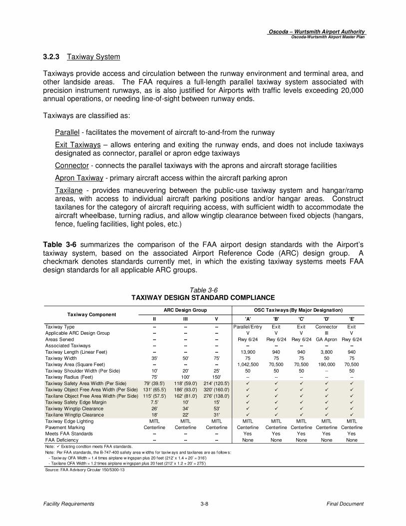
Table 3-6 summarizes the comparison of the FAA airport design standards with the Airport’s taxiway system, based on the associated Airport Reference Code (ARC) design group. A checkmark denotes standards currently met, in which the existing taxiway systems meets FAA design standards for all applicable ARC groups.
Table 3-6 TAXIWAY DESIGN STANDARD COMPLIANCE
II III V 'A' 'B' 'C' 'D' 'E'
Taxiway Type -- -- -- Parallel/Entry Exit Exit Connector Exit
Applicable ARC Design Group -- -- -- V V V III V
Areas Served -- -- -- Rwy 6/24 Rwy 6/24 Rwy 6/24 GA Apron Rwy 6/24
Associated Taxiways -- -- -- -- -- -- -- --
Taxiway Length (Linear Feet) -- -- -- 13,900 940 940 3,800 940
Taxiway Width 35' 50' 75' 75 75 75 50 75
Taxiway Area (Square Feet) -- -- -- 1,042,500 70,500 70,500 190,000 70,500
Taxiway Shoulder Width (Per Side) 10' 20' 25' 50 50 50 -- 50
Taxiway Radius (Feet) 75' 100' 150' -- -- -- -- --
Taxiway Safety Area Width (Per Side) 79' (39.5') 118' (59.0') 214' (120.5') � � � � �
Taxiway Object Free Area Width (Per Side) 131' (65.5') 186' (93.0') 320' (160.0') � � � � �
Taxilane Object Free Area Width (Per Side) 115' (57.5') 162' (81.0') 276' (138.0') � � � � �
Taxiway Safety Edge Margin 7.5' 10' 15' � � � � �
Taxiway Wingtip Clearance 26' 34' 53' � � � � �
Taxilane Wingtip Clearance 18' 22' 31' � � � � �
Taxiway Edge Lighting MITL MITL MITL MITL MITL MITL MITL MITL
Pavement Marking Centerline Centerline Centerline Centerline Centerline Centerline Centerline Centerline
Meets FAA Standards -- -- -- Yes Yes Yes Yes Yes
FAA Deficiency -- -- -- None None None None None
Note: � Existing condtion meets FAA standards.
Source: FAA Advisory Circular 150/5300-13
Note: Per FAA standards, the B-747-400 safety area w idths for taxiw ays and taxilanes are as follow s:
- Taxiw ay OFA Width = 1.4 times airplane w ingspan plus 20 feet (212’ x 1.4 + 20’ = 316’)
- Taxilane OFA Width = 1.2 times airplane w ingspan plus 20 feet (212’ x 1.2 + 20’ = 275’)
Taxiway ComponentOSC Taxiways (By Major Designation)ARC Design Group
Oscoda – Wurtsmith Airport Authority Oscoda-Wurtsmith Airport Master Plan
Facility Requirements 3-9 Final Document
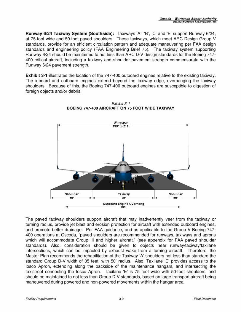
Runway 6/24 Taxiway System (Southside): Taxiways ‘A’, ‘B’, ‘C’ and ‘E’ support Runway 6/24, at 75-foot wide and 50-foot paved shoulders. These taxiways, which meet ARC Design Group V standards, provide for an efficient circulation pattern and adequate maneuvering per FAA design standards and engineering policy (FAA Engineering Brief 75). The taxiway system supporting Runway 6/24 should be maintained to not less than ARC D-V design standards for the Boeing 747-400 critical aircraft, including a taxiway and shoulder pavement strength commensurate with the Runway 6/24 pavement strength.
Exhibit 3-1 illustrates the location of the 747-400 outboard engines relative to the existing taxiway. The inboard and outboard engines extend beyond the taxiway edge, overhanging the taxiway shoulders. Because of this, the Boeing 747-400 outboard engines are susceptible to digestion of foreign objects and/or debris.
Exhibit 3-1 BOEING 747-400 AIRCRAFT ON 75 FOOT WIDE TAXIWAY
The paved taxiway shoulders support aircraft that may inadvertently veer from the taxiway or turning radius, provide jet blast and erosion protection for aircraft with extended outboard engines, and promote better drainage. Per FAA guidance, and as applicable to the Group V Boeing-747-400 operations at Oscoda, “paved shoulders are recommended for runways, taxiways and aprons which will accommodate Group III and higher aircraft.” (see appendix for FAA paved shoulder standards). Also, consideration should be given to objects near runway/taxiway/taxilane intersections, which can be impacted by exhaust wake from a turning aircraft. Therefore, the Master Plan recommends the rehabilitation of the Taxiway ‘A’ shoulders not less than standard the standard Group D-V width of 35 feet, with 50’ radius. Also, Taxilane ‘E’ provides access to the Iosco Apron, extending along the backside of the maintenance hangars, and intersecting the taxistreet connecting the Iosco Apron. Taxilane ‘E’ is 75 feet wide with 50-foot shoulders, and should be maintained to not less than Group D-V standards, based on large transport aircraft being maneuvered during powered and non-powered movements within the hangar area.

Oscoda – Wurtsmith Airport Authority Oscoda-Wurtsmith Airport Master Plan
Facility Requirements 3-10 Final Document
General Aviation Taxiway System: Taxiway ‘D’ provides access to the terminal building apron, the Fixed Base Operator (FBO) location, and general aviation hangars. Taxiway ‘D’ is 50 feet wide and meets Design Group III standards, which includes large-cabin business jets and cargo-type aircraft representative of the larger aircraft requiring access to this area. Runway 6/24 Taxiway System (Northside): The deactivated taxiway north of Runway 6/24 accessing the former Air Force Northside Alert Area is restricted by airfield fence. This area is occasionally leased for special non-aeronautical events, and is targeted for prospective large aircraft parking and other aviation developments. If used for aeronautical purposes, the taxiway system and parking area should conform to FAA standards for the types of aircraft using this area.
3.3 AIRPORT PAVEMENTS
3.3.1 Airfield Pavement Strength Pavement strength requirements are determined by the flight frequency, operating weights and wheel configuration of the critical design aircraft. The Boeing 747, as the Airport’s critical design aircraft, has an operating empty weight of 400,000 pounds and a maximum certified takeoff weight of 900,000 pounds. Most large transport cargo wide-body jets range from 250,000 to 900,000 pounds, with aircraft over 200,000 pounds usually having a dual-tandem wheel gear (DTWG) configuration. At Oscoda, the Boeing 747 arrivals and departures are configured for light loads, characteristic of weights operated for maintenance and repair flights. The Runway 6/24 pavement strength is 550,000 pounds (DTWG), sufficient to accommodate the existing and future Boeing 747 critical design aircraft when operating at normal aircraft maintenance and repair configurations. The planned crosswind Runway 18/36 pavement strength is 12,500 pounds, sufficient to accommodate most general aviation piston and smaller turboprop aircraft. Table 3-9 summarizes the facility needs for pavement strength requirements for during the 20-year planning period. 3.3.2 Pavement Condition (Maintenance and Rehabilitation)
Exhibit 3-2 depicts the 2010 Pavement Condition Index (PCI) map for the airfield pavements. The PCI is a visual pavement analysis of surface distresses, and assigns a value between 0 and 100 points indexed by color-code to correspond with the types of pavement repairs anticipated; 0 representing failed to 100 for newer pavements in pristine condition. The following is the rating index for score, color-code and pavement repairs: • 75 to 100 points – Green - Preventative Maintenance • 40 to 75 points – Yellow/Orange - Rehabilitation • 0 to 40 points – Red - Major Rehabilitation / Reconstruction Pavement deterioration progresses along a non-linear timeline. Therefore, the deferment of pavement improvement projects results more involved pavement repairs, and a proportionally higher cost.

Oscoda – Wurtsmith Airport Authority Oscoda-Wurtsmith Airport Master Plan
Facility Requirements 3-11 Final Document
Exhibit 3-2 AIRFIELD PAVEMENT CONDITION REPORT (PCI)
Source: MDOT PCI Study (2010)
Table 3-7 is the Michigan PCI scoring thresholds per aircraft category, identifying the score at which pavement reaches a PCI value in which rehabilitation should commence. For larger Category D aircraft, such as the Airport’s Boeing 747 critical aircraft, the pavement rehabilitation process is initiated based on a higher PCI value.
Table 3-7 MICHIGAN CRITICAL PCI VALUES
Runway Design
Category *Branch Use PCI Value
Runway 60
Taxiway 50
Apron 50
Runway 60
Taxiway 50
Apron 50
Runway 65
Taxiway 55
Apron 55
Runway 70
Taxiway 60
Apron 55* Per FAA AC 150-5300-13.
Category A Aircraft
Category B Aircraft
Category C Aircraft
Category D Aircraft
Parallel Taxiway System (A, B, C)
Runway 6/24 (11,800’ x 200’)
Iosco Apron
6
Former North Alert Apron
24
General Aviation Apron & FBO Ramp
Runway 6-24
Oscoda – Wurtsmith Airport Authority Oscoda-Wurtsmith Airport Master Plan
Facility Requirements 3-12 Final Document
The following is an overview of the PCI results for airfield and terminal pavements, in which a pavement improvement and phasing plan utilizing the PCI study findings is evaluated and developed in subsequent master plan chapters:
Airfield Pavements: The PCI study indicates the runway and taxiway system requires rehabilitation within the next five to ten years. The rehabilitation projects should also include the paved shoulder areas, which were not assessed as part of the PCI study. Terminal Apron / Taxiway-Taxilane Pavements: The PCI study indicates rehabilitation of the remaining Iosco Apron, and reconstruction of the associated Iosco Apron taxilanes within the next three to five years. The Main General Aviation Apron and the FBO ramp, which were originally constructed with portland concrete cement and asphalt overlaid, are generally rated in good condition (shoulders excluded). Rehabilitation of the North Alert Apron is dependent on future tenant/user demands.
3.4 AIRPORT NAVIGATION AID AND LIGHTING
3.4.1 Navigational-Instrument-Visual Aids (NAVAIDs)
The Runway 6 end has a RNAV (GPS) instrument approach procedure with localizer performance with vertical guidance (LPV) minimums as low as ¾-mile. The Runway 6 end is planned to ultimately accommodate GPS/WAAS precision instrument capabilities having positive vertical guidance with minimums as low as ¾-mile (no approach light system), when those standards are determined by the FAA. The AuSable high altitude VOR-DME, which supports enroute airways and an instrument procedure to Runway 6, is planned to remain in operation at the current location until obsolete. Table 3-9 summarizes the 20-year navigational and lighting aid facility needs. 3.4.2 Airfield Signage and Marking
Runway and taxiway guidance signs are to be installed in accordance with the FAA Advisory Circular 150/5340-18, Standards for Airport Signage Systems, and in the future, to meet Safety Management System (SMS) compliance requirements, per policy standards under development by the FAA. Due to large transport aircraft operations on Runway 6/24, it is recommended that runway distance-to-go signs be installed for both directions. Also, it is recommended that Taxiway ‘D’ signage and marking improvements be performed to provide better wayfinding for aircraft maneuvering between the Runway 24 end and the general aviation terminal area. The magnetic declination obtained from the National Geophysical Data Center indicates a westward annual shift in the magnetic variation at a rate of change which will require re-numbering of Runway 6/24 to 7/25 in the future.
3.5 TERMINAL FACILITY REQUIREMENTS
Terminal facility improvements over the next 20-years are oriented towards providing new and replacement tenant buildings and hangars, expanded apron areas, and additional auto access/parking. Existing terminal facilities will also require a substantial amount of maintenance

Oscoda – Wurtsmith Airport Authority Oscoda-Wurtsmith Airport Master Plan
Facility Requirements 3-13 Final Document
and rehabilitation. Future terminal area improvements must conform to FAA airport planning standards, meet environmental compliance and incorporate applicable codes. 3.5.1 Airport Terminal and Administration Building
The 9,400 square foot Airport Terminal/Administration building (#14) is in fair condition, and provides sufficient space for administrative needs and processing general aviation users, but may require future replacement due to aging and deteriorating condition. Any future terminal building replacement would likely be sited in the same general proximity, along the main general aviation apron. The replacement terminal building could potentially house the FBO/SASO operator, or equivalent. Per the Airport’s FBO Minimum Standards, the FBO building must accommodate 800 square feet of office space, and 500 square feet of classroom. 3.5.2 Airport Support Maintenance and Equipment Buildings
The Airport Maintenance Building (#20) is used to house vehicles and equipment, and is aged and undersized for the newer generation of larger airfield equipment. This building is recommended for expansion. Airport Maintenance Building (#16) is used for general maintenance, and is sufficient for the remaining planning period. Airport Maintenance Building (#140) is used for general storage and vehicle parking, and is sufficient for the remaining planning period. The size and space allocation requirements of Airport maintenance facilities tends to be in relation to the increase in the airfield facilities and grounds-maintenance area. 3.5.3 Iosco Apron
Expansion of the Iosco Apron is recommended to accommodate future aircraft maintenance and repair (MRO) developments, including; ramp to support future buildings and hangars, to provide an additional aircraft parking and maneuvering area, a dedicated location for aircraft engine run-ups and aircraft demolition. The expansion would be a multi-phased project, and include drainage, lighting and signage improvements. 3.5.4 Airport General Aviation Apron
The general aviation apron provides sufficient maneuvering and parking during normal peak-periods for the projected level of itinerant general aviation activity, including fixed-wing and rotorcraft aircraft. Typically, the apron area is designed to provide approximately 40 percent of the peak/design day itinerant aircraft, plus based aircraft space requirements. FAA airport planning criteria recommends 360 square yards (3,240 square feet) per itinerant aircraft space, and approximately 300 square yards (2,700 square feet) per based aircraft. Apron recommendations include a dedicated marked helicopter landing area. Ultimately, a portion of the abandoned apron area may need to be converted into active pavement in the event the FBO/SASO or future tenant locates facilities to the main apron flightline. The apron provides limited frontage to construct new and replacement terminal facilities. Per the Airport’s FBO Minimum Standards, the minimum FBO ramp area is 2,500 square feet.
Oscoda – Wurtsmith Airport Authority Oscoda-Wurtsmith Airport Master Plan
Facility Requirements 3-14 Final Document
3.5.5 General Aviation / Fixed Base Operator (FBO) Hangars/Taxilanes
General aviation hangar space is nearing capacity, with additional hangar space and paved areas needed to accommodate anticipated and forecasted based aircraft users. Rehabilitation of the FBO hangars will need to be considered as part of accommodating additional hangar facilities, as it is assumed all future based aircraft will be hangared. The general aviation hangar area should be developed to not less than Design Group II aircraft standards, representative of twin-piston and small turboprop aircraft. The majority of future hangar space is expected to be satisfied by T-hangars and individual box hangars. In addition, the trend towards larger special-purpose common hangars can be expected, including those with attached business/office space. Typically, single-engine planes require 1,000 to 1,200 square feet, 1,400 to 2,500 square feet for twin-piston aircraft, about 2,000 square feet for helicopters, and at least 3,000 square feet for business aircraft, including small cabin business jets. Per the Airport’s FBO Minimum Standards, the minimum hangar size is 5,000 square feet. 3.5.6 Airport Auto Access / Entrance Road
The existing Airport roadway network was constructed to support military base facilities, and is not necessarily conducive to the civilian roadway network. Roadway modifications for the Airport Entrance are recommended to provide improved terminal wayfinding, in addition to future roadway extensions to access new on-Airport developments. 3.5.7 Auto Parking
Public auto parking for the terminal building consists of two adjacent surface lots totaling about 32 parking spaces. The lot size is adequate, but might need to be reconfigured in the future based on the possible reconfiguration of the Airport entrance road and other terminal improvements. In addition, future expansion and new construction of auto parking lots is recommended to support tenants located at the Iosco Apron, including upgrades to fencing, gates and lighting. For the based aircraft owners, no dedicated auto parking is recommended, as pilots commonly park at their individual hangar via control-gated auto access. 3.5.8 Aircraft Fuel Storage
The Airport Authority does not conduct aircraft fueling, as all fuel storage and dispensing is performed by airport operators (FBO) and tenants. 3.5.9 Aircraft De-Icing
De-icing activities are conducted by the FBO and select tenants on their respective apron areas, and assume responsibility of fluid storage and management. 3.5.10 Airport Perimeter Roadway
It is recommended that the north section of the Airport Perimeter Roadway provide a connection with Price Road.

Oscoda – Wurtsmith Airport Authority Oscoda-Wurtsmith Airport Master Plan
Facility Requirements 3-15 Final Document
3.5.11 Airport Security Fencing
A system of perimeter fencing (6’ to 10’ tall), locked and monitored auto access gates, and secured pedestrian access gates are provided to control unauthorized access onto the Airport operating areas. The Airport does not report problems associated with uncontrolled access or wildlife incursions. It is recommended a Wildlife Hazard Assessment Study and Safety Management Study (SMS) be conducted for the Airport to determine future fence and gate access needs and improvements. The typical fence height to restrict deer is 8 to 10 feet tall.
3.5.12 Airport Utilities
It is recommended that the northside terminal area be supplied with an extension of the regional natural gas line. The preferred gas line route should avoid the airfield safety areas. Other utilities will require extension to new building/hangar development areas.
3.5.13 Airport Land Acquisition
Future Airport land interests include:
- Remaining Air Force Base property, approximately 110 acres, to be transferred from the United States to the Airport Authority.
- Runway Protection Zone for future Runway 6 precision approach - Crosswind Runway 18/36 - Airport entrance road re-alignment
3.6 SUPPORT FACILITIES
3.6.1 Aircraft Fuel Storage
There are no known aircraft fuel storage deficiencies. Any future fuel storage and dispensing facilities must conform to Airport requirements, and other fuel and fire code regulations. 3.6.2 Maintenance, Repair and Overhaul (MRO) Facilities
Given anticipated growth of the aircraft maintenance and repair (MRO) services, additional space allocation should be planned and further reserved for MRO tenant expansion, including; office buildings, storage facilities, various types and sizes of hangars, apron/ramp area, and auto parking. As part of the MRO development plan, a future aircraft run-up area or ground run-up enclosure is recommended for testing aircraft engines within an enclosed facility. 3.6.3 Aircraft Rescue and Fire Fighting (ARFF) Facility
Aircraft Rescue and Fire Firefighting (ARFF) facilities and vehicle equipment assist in aircraft emergencies and accidents. At Oscoda, ARFF facilities may be necessary in order to satisfy aircraft maintenance and repair (MRO) operating and insurance requirements, principally for large transport cargo aircraft.
Oscoda – Wurtsmith Airport Authority Oscoda-Wurtsmith Airport Master Plan
Facility Requirements 3-16 Final Document
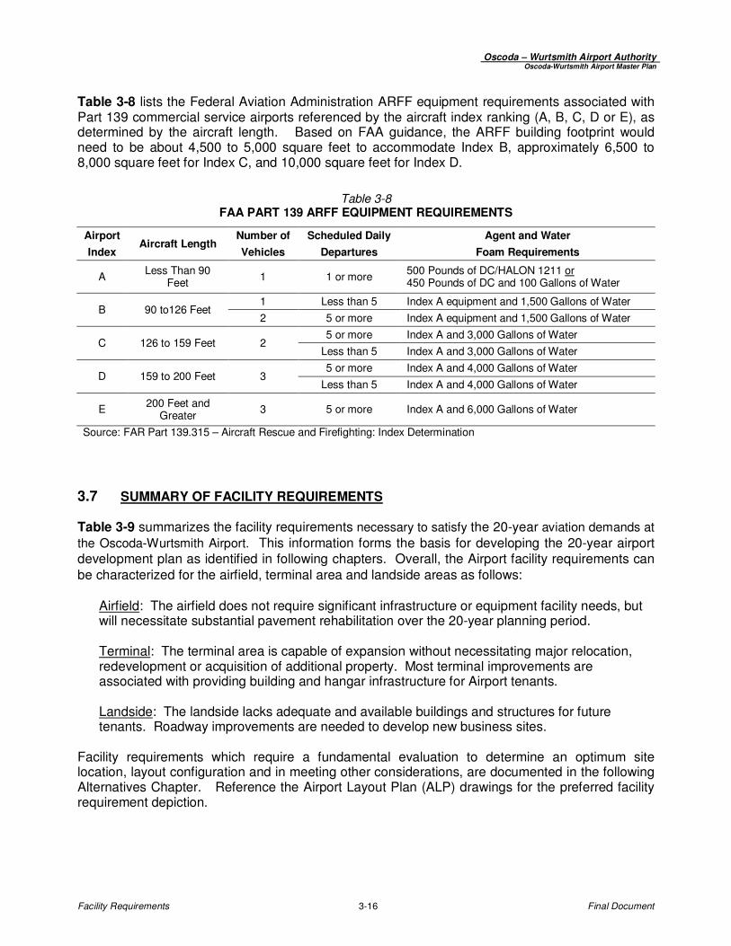
Table 3-8 lists the Federal Aviation Administration ARFF equipment requirements associated with Part 139 commercial service airports referenced by the aircraft index ranking (A, B, C, D or E), as determined by the aircraft length. Based on FAA guidance, the ARFF building footprint would need to be about 4,500 to 5,000 square feet to accommodate Index B, approximately 6,500 to 8,000 square feet for Index C, and 10,000 square feet for Index D.
Table 3-8 FAA PART 139 ARFF EQUIPMENT REQUIREMENTS
Airport Aircraft Length
Number of Scheduled Daily Agent and Water
Index Vehicles Departures Foam Requirements
A Less Than 90
Feet 1 1 or more
500 Pounds of DC/HALON 1211 or 450 Pounds of DC and 100 Gallons of Water
B 90 to126 Feet 1 Less than 5 Index A equipment and 1,500 Gallons of Water
2 5 or more Index A equipment and 1,500 Gallons of Water
C 126 to 159 Feet 2 5 or more Index A and 3,000 Gallons of Water
Less than 5 Index A and 3,000 Gallons of Water
D 159 to 200 Feet 3 5 or more Index A and 4,000 Gallons of Water
Less than 5 Index A and 4,000 Gallons of Water
E 200 Feet and
Greater 3 5 or more Index A and 6,000 Gallons of Water
Source: FAR Part 139.315 – Aircraft Rescue and Firefighting: Index Determination
3.7 SUMMARY OF FACILITY REQUIREMENTS
Table 3-9 summarizes the facility requirements necessary to satisfy the 20-year aviation demands at
the Oscoda-Wurtsmith Airport. This information forms the basis for developing the 20-year airport development plan as identified in following chapters. Overall, the Airport facility requirements can be characterized for the airfield, terminal area and landside areas as follows:
Airfield: The airfield does not require significant infrastructure or equipment facility needs, but will necessitate substantial pavement rehabilitation over the 20-year planning period. Terminal: The terminal area is capable of expansion without necessitating major relocation, redevelopment or acquisition of additional property. Most terminal improvements are associated with providing building and hangar infrastructure for Airport tenants. Landside: The landside lacks adequate and available buildings and structures for future tenants. Roadway improvements are needed to develop new business sites.
Facility requirements which require a fundamental evaluation to determine an optimum site location, layout configuration and in meeting other considerations, are documented in the following Alternatives Chapter. Reference the Airport Layout Plan (ALP) drawings for the preferred facility requirement depiction.

Oscoda – Wurtsmith Airport Authority Oscoda-Wurtsmith Airport Master Plan
Facility Requirements 3-17 Final Document
Table 3-9 FACILITY REQUIREMENT SUMMARY
Facility Requirement Existing (2010) 2015 (5-Year) 2020 (10-Year) 2030 (20-Year)
Runway 6/24:
ARC Category D-V D-V D-V D-V
Runway Numbers Rwy 6/24 Rwy 7/25 Rwy 7/25 Rwy 7/25
Length x Width 11,800' x 200' 11,800' x 200' 11,800' x 200' 11,800' x 200'
Blast Pad 300' x 1,000' 280' x 400' 280' x 400' 280' x 400'
Paved Shoulders 50' 35' to 50' 35' to 50' 35' to 50'
Pavement Strength (Gear) 550,000 (DDT) 550,000 (DDT) 550,000 (DDT) 550,000 (DDT)
Edge Lighting HIRL HIRL HIRL HIRL
Instrument Capabilities PIR (Rwy 24) PIR (Rwy 24) PIR (Rwy 6 & 24) PIR (Rwy 6 & 24)
Runway Aids
Planned Runway18/36:
ARC Category -- -- B-II B-II
Length x Width -- -- 4,200' x 75' 5,000' x 75'
Pavement Strength (Gear) -- -- 12,500 SWG 12,500 SWG
Edge Lighting -- -- MIRL MIRL
Runway Aids -- -- PAPI-2 | REIL PAPI-2 | REIL
Instrument Capabilities -- -- Non-Precision Non-Precision
Taxiway -- -- Partial - 35' Wide Full - 35' Wide
Taxiway Segments 'A', 'B', 'C', 'E' 'A', 'B', 'C', 'E' 'A', 'B', 'C', 'E' 'A', 'B', 'C', 'E'
ARC Category ARC D-V ARC D-V ARC D-V ARC D-V
Width (Shoulder) 75' (50') 75' (35' to 50') 75' (35' to 50') 75' (35' to 50')
Pavement Strength (Gear) 550,000 DDT 550,000 DDT 550,000 DDT 550,000 DDT
Edge Lighting MITL MITL MITL MITL
Taxiway Segments 'D' 'D' 'D' 'D'
ARC Category ARC C-III ARC C-III ARC C-III ARC C-III
Width / Shoulder 50' / N/A 50' / N/A 50' / N/A 50' / N/A
Pavement Strength (Gear) 60,000 DT 60,000 DT 60,000 DT 60,000 DT
NAVAIDSILS, RNAV (GPS),
VOR-DME
ILS, RNAV (GPS),
VOR-DME
ILS, RNAV (GPS),
WAAS, VOR-DME
ILS, RNAV (GPS),
WAAS, VOR-DME
Weather System AWOS-3 AWOS-3 AWOS-3 AWOS-3
Ground Communications -- GCO GCO GCO
Terminal Building (SF) 9,400 9,400 9,400 10,000 to 12,000
SRE Building #20 (SF) 15,000 15,000+ 15,000+ 15,000+
SRE Storage Building #140 (SF) 25,000 25,000± 25,000± 25,000±
General Aviation Apron (SY) 24,000 24,000 24,000 24,000+
Iosco Apron / Run-Up (SY) 192,500 192,500 192,500 to 235,000 235,000 to 275,000
T-Hangars (Storage Units) 10 Units 20 Units 28 Units 36 Units
Box Hangars (Units) -- -- 2± 4±
Conventional Hangars Various Per Tenant Demand Per Tenant Demand Per Tenant Demand
Fuel Storage (100LL | Jet A) 15,000 | 20,000 15,000 | 20,000 15,000 | 20,000 15,000 | 20,000
Airport Fencing 8' to 10' Fence Per Study Per Study Per Study
Terminal Parking (Public Use) +32 Spaces +32 Spaces +32 Spaces Potential Expansion
MRO Auto Parking (Public Use) ±257,000 SF Potential Expansion Potential Expansion Potential Expansion
AIRFIELD
ILS-CAT I, MALSR, PAPI-4L, REIL
Distance-to-Go Marker Signs
NAVIGATIONAL AIDS
AVIATION SUPPORT FACILITIES
ACCESS, CIRCULATION AND PARKING