oscilloscope-, monitor-, radar- and flying-spot-tubes
TRANSCRIPT
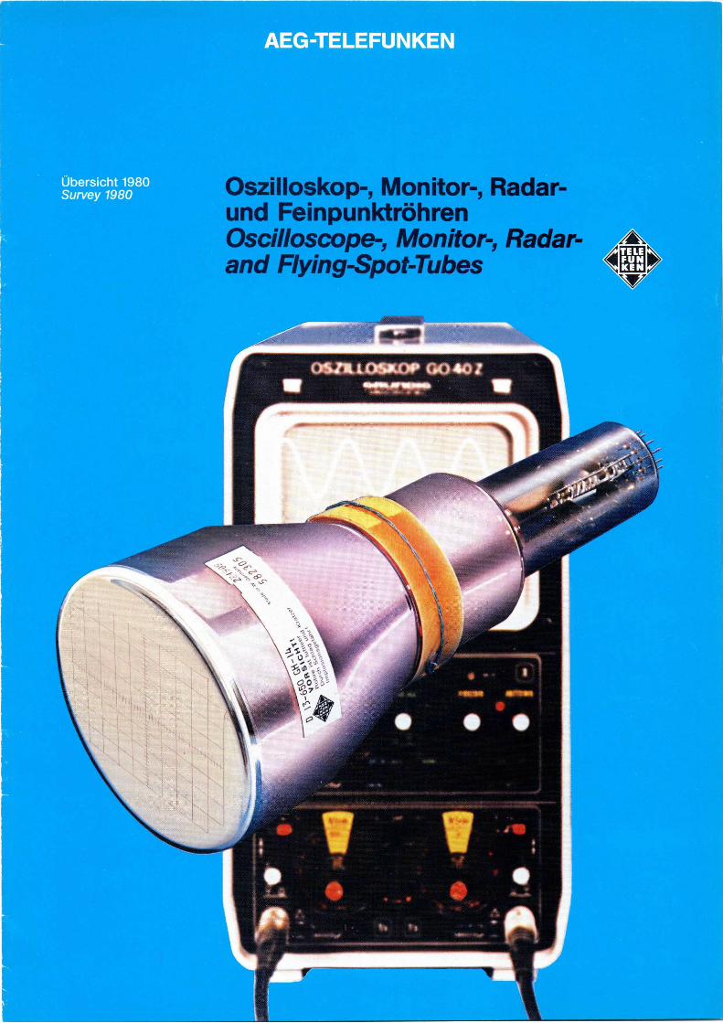
Oszilloskop-, Monitor-, Radar-und Feinpunktröhren Oscilloscope-, Monitor-, Radar- T
and Flying-Spot-Tubes C KEN v

AEG TELEFUNKEN bietet als einer der größten Hersteller von Elektronenstrahlröhren ein umfangreiches Programm.
Oszilloskopröhren für alle Anwendungsgebiete.
Monitorröhren für Industrie, Elektromedizin und MIL-Anwendungen.
Feinpunktröhren für Schreib- und Abtastzwecke.
Radarröhren Ein- und Mehrfarbschirme (Penetron).
Sonderröhren nach Kundenspezifikationen.
Dieser Kurzkatalog vermittelt Ihnen die wichtigsten technischen Daten für Röhren, die wir für Neu-Entwicklung und Erstbestückung anbieten.
Weitere Informationen übersenden wir Ihnen gern auf Anforderung.
Änderungen, die dem technischen Fortschritt dienen, sind vorbehalten.
,u~monu~ln~nu , ,~~p'~~"I,I
~nn ' ~~\\\\\II~ ,~~„~~~ ~
% H~\!~!! 1 i ar.... ~ ~tRcFe: i~'~;:,~.
AEG-TELEFUNKEN is one of the most important manufacturer of cathode ray tubes and offers a comprehensive program.
Oscilloscope tubes for all purposes.
Monitor tubes for industrie, electromedicine and MIL-applications.
Flying spot tubes for writing and scanning applications.
Radar tubes single- and multicolour screens (Penetron).
Special tubes according to customer specifications.
This catalogue summarizes the most important Batas of cathode ray tubes, we offer for new developments and product applications.
More detailed information maybe supplied upon request.
We reserve the right to improve the design which serves the technical advancement.
Röhrenwerk Tube factory Ulm, Söflinger Strasse
2
„Stuttgarter Luftbild, freigeg. durch Regierungs-Präsidium Stuttgart Nr. 9/38093"

Inhalt Contents
Einstrahlröhren für Oszilloskope Single-beam tubes for oscilloscopes
Typ •Type Seite Page Typ •Type Seite •Page
D 3-11 4/5 D 13-41 6/7 D 3-111 D 13-620 D 5-100 D 13-621 D 7-16 D 13-622 D 7-180 D 13-650 D 7-210 D 14-11 D 9-10 D 14-111 D 10-19 D 14-131 D 10-191 D 14-132 D 10-193 D 14-140 8/9 D 10-194 D 14-220 D 10-250 D 14-221 D 10-260 D 14-222 D 10-650 6/7 D 14-230 D 12-100 D 14-231 D 12-101 D 14-650 D 12-110 D 18-11 D 12-270 D 18-150 D 13-40 D 18-650
Zweistrahlröhre für Oszilloskope Dual-beam tube for oscilloscopes
Typ ~ Type Seite ~ Page
E 14-120 8/9
Monitorröhren Monitor tubes
Typ Type Seite Page Typ •Type Seite Page
M 14-100 10/11 M 31-150 10/11 M 17-11 M 31-200 M 17-111 M 38-121 M 17-210 M 44-120 M 23-100 M 44-121 M 28-12 M 44-130 M 31-120 M 50-120 M 31-140 M 61-120
Wichtige Hinweise
• Die Röhren sind luftleer. Bei mechanischer Beschädigung
(durch Schlag, Kratzer o. ä.) besteht Implosionsgefahr.
• Der Nachbeschleunigungsanschluß der Röhren kann
infolge der Röhrenkapazitäten auch noch lange Zeit nach
dem Abschalten Hochspannung führen.
Zur Entladung sollen daher die letzte Beschleunigungs-
elektrode und der leitende Außenbelag mehrmals kurz-
geschlossen bzw.geerdet werden.
• Bei Betrieb der Röhren mit Beschleunigungsspannungen
über 5 kV werden schwache Röntgenstrahlen erzeugt.
Bei Betrieb innerhalb der Grenzdaten bleibt die Dosis-
leistung unter dem zulässigen Wert von 36 • 10-12 A/kg
Gesetzliche und sonstige Vorschriften, in denen u. a.
zulässige Höchstwerte und/oder eine Kennzeichnungs-
pflicht für die Geräte festgelegt sind (z.B. Röntgen-
verordnung, Arbeitsschutz und Unfallverhütungsvorschriften,
Umweltschutzgesetze) sind vom Anwender (insbesondere
Gerätehersteller, Betreiber usw.) in jedem Falle zu
beachten.
Important notes
• The tube is evacuated. Mechanical damage (by strike,
scratches etc.) may cause danger of implosion.
Radarröhren • Due to the tube capacitances the post accelerating voltage Radar tubes connector of the tube may carry HT for a longer period
Typ •Type Seite •Page Typ ~ Type Seite •Page
F 7-100 10/11 F 42-10 10/it F 8-100 F 42-101 F 17-100 F 58-100 F 18-100 10 KP... (K 1987) 10 WP... F 31-150
Feinpunktröhren Flying spot tubes
Typ Type Seite •Page
Q 13-10 10/11 O 13-120 O 23-100 O 25-100 O 28-103
after deenergizing.
The last accelerating electrode and the conducting outer-
coating must be discharged by shorting them several times
or by connecting them to ground potential.
• During operation with acceleration voltages in excess
of 5 kV a small amount of X-rays are being produced.
At operation within the maximum ratings the dose rate
remains below the permissible amount of 36 • ]0-12 A/kg
All government regulations and other specifications must be
strictly observed by users, especially by OEM's.
Uie jeweils lieferbaren Schirmarten sind den Datenblättern zu entnehmen. Refer to data sheets for deliverable screen types.
3

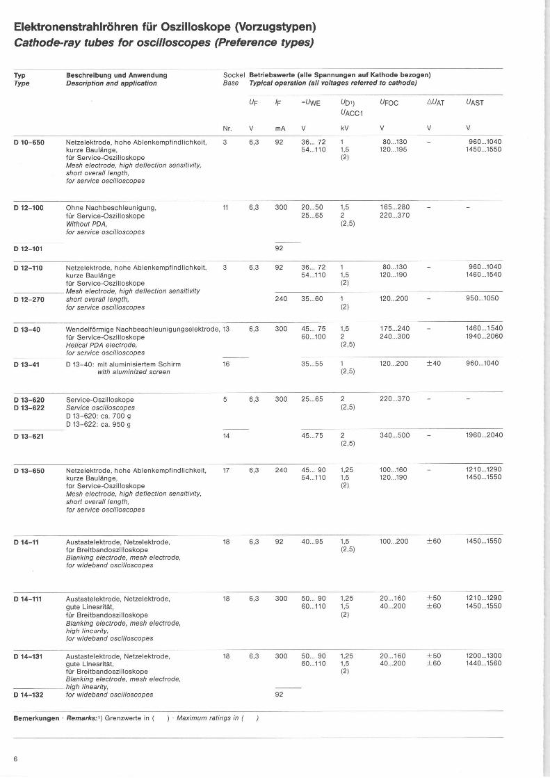
Elektronenstrahlröhren für Oszilloskope (Vorzugstypen) Cathode-ray tubes for oscilloscopes (Preference types)
Typ Beschreibung und Anwendung Sockel Betriebswerte (alle Spannungen auf Kathode bezogen) Type Description and application Base Typical operation (all voltages referred to cathode)
Nr.
D 3-11 Allgemeine Anzeigezwecke 1 General purpose indicating devices
D 3-111
D 5-100 Taschenfernsehgeräte 2 Pocket TV sets
D 7-16 Kleinoszilloskope und Anzeigegeräte 4 Small sized oscilloscopes and indicating devices
D 7-180 Kleinoszilloskope und Anzeigegeräte 2 Small sized oscilloscopes and indicating devices
D 7-210 Service-Oszilloskope 5 Service oscilloscopes
D 9-10 Kleine, tragbare Oszilloskope 6 Small sized portable oscilloscopes
D 10-19 Netzelektrode, aluminisierter Schirm, 7 große Helligkeit Mesh electrode, aluminized screen, high brightness
D 10-191 Netzelektrode, für tragbare Oszilloskope Mesh electrode, for portable oscilloscopes D 10-194: mit aluminisiertem Schirm
D 10-194 with aluminized screen
D 10-193 Austastelektrode, Netzelektrode, 8 für tragbare Oszilloskope Blanking electrode, mesh electrode, for portable oscilloscopes
D 10-250 WendelfHrmige Nachbeschleunigungselektrode, 9 für tragbare Oszilloskope Helical PDA electrode, for portable oscilloscopes
D 10-260 Ohne Nachbeschleunigung, 5 für Kleinoszilloskope Without PDA, for small sized oscilloscopes
Bemerkungen • Remarks: ~) Grenzwerte in ( ) Maximum ratings in (
UF
V
IF
mA
-WVE
V
UD~) VACC1
kV
UFOC
V
~VAT
V
~AST
V
6,3 300 7...21 14...42
0,5 1 (1,5)
50...150 100...300
92
0,55 60 18...35 2 (2,5)
150...250 - 1900...2100
6,3 92 22...38 0,8 (1,5)
50...90
0,55 60 18...35 2 (2,5)
150...250 - 1900...2100
6,3 300 15...35 1 (2,5)
100...180
6,3 92 23...47 45...95
1 2 (2,75)
120...170 200...340
6,3 92 50...90 75...135
1 1,5 (2)
20...60 40...90
960...1040 1460...1540
45...95 0,5 (1)
0...40 - 460...540
35...70 0,5 (1)
40...90 - 460...540
6,3 92 45...95 0,5 (1)
90...130 ±40 460...540
6,3 92 30...70 40...90
0,75 1 (2)
30... 70 40...100
- 700... 800 950...1050
6,3 300 19...50 1,5 (2,5)
150...270
)
4
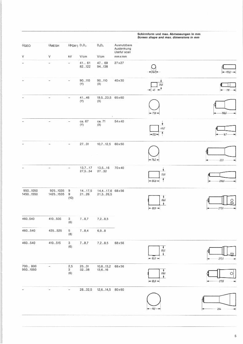
Schirmform und max. Abmessungen in mm Screen shape and max. dimensions in mm
UGEO
V
UMESH
V
UPDA~) D,D2
kV V/cm
D3D,
V/cm
Ausnutzbare Auslenkung Useful scan mmxmm
- 41... 61 82...122
47...69 94...138
27x27
- - - 90...110 (Y)
90...110 (X)
40x30
- - - 41...46 19,5...23,5 65x60 (Y) (X)
- - - ca.67 ca.71 54x40 (Y) (X)
- - - 27...31 10,7...12,5 60x50
- - - 13,7...17 13,5...16 70x40 27,5...34 27...32
950...1050 925...1035 9 14...17,5 14,4...17,6 68x56 1450...1550 1425...1535 9 21...26 21,5...26,5
(10)
460..540 410...505 3 7...8,7 7,2...8,5 (6)
460...540 435...525 5 7...8,4 6,9...8 (8)
460...540 410...515 3 7...8,7 7,2...8,5 68x56 (6)
700... 800 2,5 25...31 10,8...13,2 68x56 950...1050 3 32...38 13,6...16
(6)
- - - 28...32,5 12,6...14,5 80x60
103,2
1865
51,8
80,8
23
I
206h5 ~
89,5 ~ ~ O
= 2175 ►~
117,5
254
5
Elektronenstrahlröhren für Oszilloskope (Vorzugstypen) Cathode-ray tubes for oscilloscopes (Preference types)
Typ Beschreibung und Anwendung Sockel Betriebswerte (alle Spannungen auf Kathode bezogen) Type Description and application Base Typical operation (all voltages referred to cathode)
Nr.
D 10-650 Netzelektrode, hohe Ablenkempfindlichkeit, 3 kurze Baulänge, für Service-Oszilloskope Mesh electrode, high deflection sensitivity, short overall length, for service oscilloscopes
D 12-100 Ohne Nachbeschleunigung, 11 für Service-Oszilloskope Without PDA, for service oscilloscopes
D 12-101
D 12-110 Netzelektrode, hohe Ablenkempfindlichkeit, 3 kurze Baulänge für Service-Oszilloskope
Mesh electrode, high deflection sensitivity D 12-270 short overall length,
for service oscilloscopes
D 13-40 Wendelförmige Nachbeschleunigungselektrode, 13 für Service-Oszilloskope Helical PDA electrode, for service oscilloscopes
D 13-41 D 13-40: mit aluminisiertem Schirm 16 with aluminized screen
D 13-620 Service-Oszilloskope 5 D 13-622 Service oscilloscopes
D 13-620: ca. 700 g D 13-622: ca. 950 g
D 13-621 14
D 13-650 Netzelektrode, hohe Ablenkempfindlichkeit, 17 kurze Baulänge, für Service-Oszilloskope Mesh electrode, high deflection sensitivity, short overall length, for service oscilloscopes
D 14-11 Austastelektrode, Netzelektrode, für Breitbandoszilloskope Blanking electrode, mesh electrode, for wideband oscilloscopes
18
D 14-111 Austastelektrode, Netzelektrode, 18 gute Linearität, für Breitbandoszilloskope Blanking electrode, mesh electrode, high linearity, for wideband oscilloscopes
D 14-131 Austastelektrode, Netzelektrode, 18 gute Linearität, für Breitbandoszilloskope Blanking electrode, mesh electrode,
high linearity, D 14-132 for wideband oscilloscopes
Bemerkungen •Remarks:) Grenzwerte in ( ) Maximum ratings in (
OF
V
IF
mA
-WVE
V
UDC) UACC1
kV
UFOC
V
DUAT
V
OAST
V
6,3 92 36... 72 54...110
1 1,5 (2)
80...130 120...195
960...1040 1450...1550
6,3 300 20...50 25...65
1,5 2 (2,5)
165...280 220...370
92
6,3 92 36... 72 54...110
1 1,5 (2)
80...130 120...190
- 960...1040 1460...1540
240 35...60 1 (2)
120...200 - 950...1050
6,3 300 45... 75 60...100
1,5 2 (2,5)
175...240 240...300
1460...1540 1940...2060
35...55 1 (2,5)
120...200 ±40 960...1040
6,3 300 25...65 2 (2,5)
220...370
45...75 2 (2,5)
340...500 - 1960...2040
6,3 240 45... 90 54...110
1,25 1,5 (2)
100...160 120...190
1210...1290 1450...1550
6,3 92 40...95 1,5 (2,5)
100...200 ±60 1450...1550
6,3 300 50... 90 60...110
1,25 1,5 (2)
20...160 40...200
±50 ±60
1210...1290 1450...1550
6,3 300 50... 90 60...110
1,25 1,5 (2)
20...160 40...200
±50 ±60
1200...1300 1440...1560
92
)
6
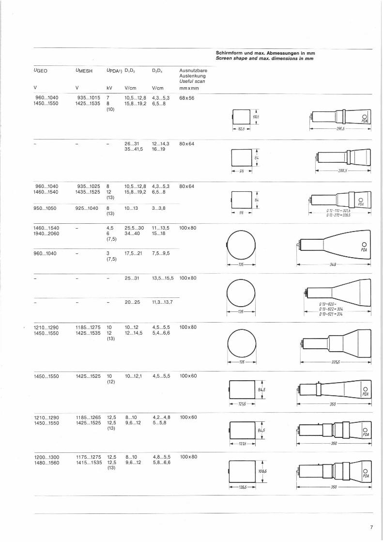
UGEO
V
~MESH
V
UPDA~) D,D2
kV V/cm
D3D4
V/cm
Ausnutzbare Auslenkung Useful scan
mmxmm
960...1040 935...1015 7 10,5...12,8 4,3...5,3 68x56 1450...1550 1425...1535 8 15,8...19,2 6,5...8
(10)
- - - 26...31 12...14,3 80x64 35...41,5 16...19
960...1040 935...1025 8 10,5...12,8 4,3...5,3 80x64 1460...1540 1435...1525 12 15,8...19,2 6,5...8
(13)
950...1050 925...1040 8 10...13 3...3,8 (13)
1460...1540 - 4,5 25,5...30 11...13,5 100x80 1940...2060 6 34...40 15...18
(7,5)
960...1040 3 17,5...21 7,5...9,5 (7,5)
- - 25...31 13,5...15,5 100x80
- - - 20...25 11,3...13,7
1210...1290 1185...1275 10 10...12 4,5...5,5 100x80 1450...1550 1425...1535 12 12...14,5 5,4...6,6
(13)
1450...1550 1425...1525 10 10...12,1 4,5...5,5 100x60 (12)
1210...1290 1185...1265 12,5 8...10 4,2...4,8 100x60 1450...1550 1425...1525 12,5 9,6...12 5...5,8
(13)
1200...1300 1175...1275 12,5 8...10 4,8...5,5 100x80 1480...1560 1415...1535 12,5 9,6...12 5,8...6,6
(13)
Schirmform und max. Abmessungen in mm Screen shape and max. dimensions in mm
~ 59,5 ~
O POA
82,5 296 6
~ g4
~
- c=
~ 98--►I 158,5
~ 86
~
O POA
011-110=301,5_ 98~ F _ 012-170=325,5
135
013-510- 013-511- 304 D 13-521-334
135
1245—~
~ 84,5
~
~
r
0 350
~--126,5 —i{
108,5
0 PDA
.
350
350
lO
~
7

Elektronenstrahlröhren für Oszilloskope (Vorzugstypen)
Cathode-ray tubes for oscilloscopes (Preference types)
Typ Beschreibung und Anwendung Sockel Betriebswerte (alle Spannungen auf Kathode bezogen)
Type Description and application Base Typical operation (all voltages referred to cathode)
N r.
D 14-140 Netzelektrode, sehr große Helligkeit, 19 für Ultraschall-Prüfgeräte Mesh electrode, very high brightness, for ultrasonic test sets
D 14-220 Hohe Ablenkempfindlichkeit und Genauigkeit, 20 fOr Breitbandoszilloskope High deflection sensitivity and high accuracy, for wideband oscilloscopes
D 14-221 D 14-221: sehr große Helligkeit very high brightness
D 14-230 Wendelförmige Nachbeschleunigungselektrode, 10 kurze Baulänge Helical PDA electrode, short overall length
D 14-231
D 14-650 Netzelektrode, hohe Ablenkempfindlichkeit, 3 kurze Baulänge, für Service-Oszilloskope Mesh electrode, high deflection sensitivity, short overall length, for service oscilloscopes
D 18-11 Wendelförmige Nachbeschleunigungselektrode, 12 aluminisierter Schirm Helical PDA electrode, aluminized screen
D 18-150 Netzelektrode, hohe Ablenkempfindlichkeit, 20 für Breitbandoszilloskope mit großem Bildschirm Mesh electrode, high deflection sensitivity, for wideband oscilloscopes with large screen
D 18-650 Netzelektrode, hohe Ablenkempfindlichkeit, 3 kurze Baulänge, für Oszilloskope mit großem Bildschirm Mesh electrode, high deflection sensitivity, short overall length, for oscilloscopes with large screen
E 14-120 Zweistrahlröhre, Netzelektrode, 15 hohe Ablenkempfindlichkeit und Genauigkeit Dual-beam tube, mesh electrode, high sensitivity and high accuracy
Bemerkungen • Remarks: ~) Grenzwerte in ( ) •Maximum ratings in (
UF
V
IF
mA
- WVE
V
UD~) UACC1
kV
UFOC
V
~UAT
V
OAST
V
6,3 300 38...68 50...90
1,5 2 (3)
60...200 100...250
1440-1560 1920...2080
6,3 300 50...90 1,3 (3)
200...400 Ug:__ 1,3 kV
1240...1360
80...130 2,5 (3)
400...600 - 2450...2550
6,3 300 30...60 45...90
1 1,5 (2,5)
53...93 80...140
950...1050 1450...1550
92
6,3 240 45... 90 54...110
1,25 1,5 (2)
100...160 120...190
1210...1290 1450...1550
6,3 300 50...110 2 (3)
160...350 - 1940...2060
6,3 300 77...140 2 (3)
300...600 US:2 kV
1940...2060
6,3 240 45...90 2 (2,5)
170...270 - 1940...2060
6,3 600 45...85 1,25 (2)
400...500 - 1200...1300
)
8

Schirmform und max. Abmessungen in mm Screen shape and max. dimensions in mm
~GEO
V
UMESH
V
UPDA~) D,D2
kV V/cm
D3D,
V/cm
Ausnutzbare Auslenkung Useful scan mmxmm
1450...1550 1425...1535 12 13,5...16,5 7,9...9,8 100x80 1940...2060 1915...2045 16 18...22 10,5...13
(18)
1240...1360 1215...1345 18 5,5...7,5 3...3,5 100x80 (20)
2450...2550 2425...2535 18 16...18 8...9 (20)
950...1050 3 18,6...20,4 8...10 100x80 1450...1550 4,5 24...30 11,7...14,3
(7,5)
1210...1290 1185...1275 10 10...12 4,5...5,5 100x80 1450...1550 1425...1535 12 12...14,5 5,4...6,6
(13)
1940...2060 6 24...31 14...18 150x120 (9)
1940...2060 1915...2045 18 7,6 3,8 120x100 (20)
1940...2060 1945...2045 16 ca.16 ca.6,6 120x100 (18)
1200...1300 1175...1285 12,5 ca. 12 ca.5 100x80 (15)
I
~-116,5
~ 1O8ä
1
120
~
+~
100
1
350
O POA
120
~ 100 1
~ 1I00
+ 120
304,5
~_
336,5
O POA
~ POA
~ —r
I 1~1 O PO
445 ~— us —+~ ~
121
~--146- - ►~
~ f00
1 4 35
39E
O
~ POA
~ ~
9

Elektronenstrahlröhren mit magnetischer Strahlablenkung (Vorzugstypen)
Cathode-ray tubes with magnetic beam deflection (Preference types)
Typ Beschreibung und Anwendung Sockel Betriebswerte (alle Spannungen auf Kathode bezogen) Type Description and application Base Typical operation (all voltages referred to cathode)
OF IF - WVE VACCn UFOC VACCz Ausnutzbare ~) Schirmfläche
Useful screen area
V mA V V V kV mmxmm
Monitorröhren •Monitor tubes
M 14-100 Industrielle und elektro-medizinische A 12 75 15...39 300 0...300 8 (10) 109x85
M 17-11 M 17-111
Sichtgeräte, Daten-Monitore Industrial and electro-medical
g 11 72 32...58 250 0...350 11 (13) 124x93
M 17-210 display units, E 6,3 300 60...112 600 0...400 16 (18) 124x93
M 23-100 data monitors
A 12 75 33...77 400 0...350 9(12) 183x140
M 28-12 B 11 72 32...58 250 0...350 11 (14) 228x171
M 31-200 B 11 72 32...58 250 0...350 11 (14) 257x195
M 31-120
M 31-140 Daten-Monitore, 875 Zeilen D 6,3 300 50...112 600 0...400 16 (18) 257x195
M 31-150 Data monitors, 875 lines E
M 38-121 Monitore, 875 Zeilen E 6,3 300 50...112 600 0...400 16 (18) 226x290
M 44-120 Monitors, 875 lines
346x270
M 44-121 Monitore • monitors, 1000 Zeilen • lines E 6,3 300 50...93 2500 2600...2800 18 (20) 346x270
M 44-130 Monitore • monitors, 1000 Zeilen • lines K 6,3 300 18 (20) 346x270
M 50-120 Monitore • monitors, 625 Zeilen • lines E 6,3 300 60...112 600 0...400 16 (18) 394x308
M 81-120 Monitore •monitors, 875 Zeilen • lines E 6,3 300 60...112 600 0...400 16 (18) 481 x375
Radarröhren •Radar tubes
F 7-100 Mit Planschirm With flat-faced screen
- 6,3 300 45...70 magn. 15 462
F 8-100 Mit Planschirm With flat-faced screen
- 6,3 300 50...100 - 2600 18 468,9
F 17-100 Mit Planschirm With flat-faced screen
B 11 72 32...58 250 0...350 11 4155
F 18-100 K 1987
H 6,3 300 12...20 300 0...350 10 4152
F 31-150 Mit Metailrahmen With rimguard
J 6,3 600 28...72 300 0...300 10 4279
F 42-10 Mit Metallrahmen • With rimguard C 6,3 300 62...95 300 -100...+350 12 4365 F 42-101 Ohne Metallrahmen • Without rimguard
F 58-100 E 6,3 300 60...130 2200 2000...4000 18 ~ 508
10 KP... G 6,3 600 25...70 250 magn. 9 4230
10 WP... J 6,3 600 28...72 300 0...300 10 4230
Feinpunktröhren •Flying spot tubes
Q 13-10 Linienbreite 33 Nm Line width 33 Nm
F 6,3 300 35...110 1000 magn. 20 (22) 4108
~ 13-120 Linienbreite 20 Nm Line width 20 Nm
F 6,3 300 50...100 2000 magn. 20 4108
~ 23-100 Linienbreite 25 Nm Line width 25 pm
G 6,3 300 35...110 2000 magn. 23 (25) 4195
Q 25-100 Linienbreite 50 Nm Line width 50 Nm
G 6,3 300 33...77 2000 magn. 20 (25) 4228
d 28-103 Linienbreite 25 Nm Line width 25 Nm,
G 6,3 300 35...110 2000 magn. 20 (25) 4250
Bemerkungen • Remarks: ~) Grenzwerte in ( ) Maximum ratings in ( )
10

Sockelschaltungen Base diagrams
A F
Max. Hals-~ Max. nec ~
mm
Ablenk ~ Deflection ~
°
Gesamtlänge Overall length
mm
21 70 180
21 75 204
29,6 75 225
21 90 219
21 90 250
21 90 277
110 233
29,6 90 310
110 241
29,6 110 279,5
291
29,6 110 326,5
38 110
29,6 110 319
29,6 110 370
21,2 45 187
22,5 28 244
21 75 205
22,8 70 221
38 55 466,5
38 53 613
27,5 57 681,5
38 50 457
38 50 440
38 42 430
38 40 505
35,5 45 764
38 50 645
38 50 680
F
B G
WE
WE F
C H
FOC
~© ~\
~~Z ~ 11 ~~' wE \~' 12~
f F
D J
FOC FDi
f
wE
E K
11

1 6 11 16
2 7 12 17
3 8 13 18
uZ
4CC7 ©~.~ 1G i.V.
FOC p3 '~
K O ~ Gz G4 G'~13 ~ WE
AST
03
MfSN
O T 14 G4 O O O GfG
~ PGA
4 9 14 19
5 10 15 20

AEG-TELEFUNKEN Serienprodukte Geschäftsbereich Röhren und Baugruppen Söflinger Straße 100 7900 Ulm/Donau Telefon (0731) 191-1 Telex 712601
0 _U
~ ~ n m ¢ m `ma ~ LLm
C_
~ d ~ ä
~ ~ s ~ ~ ~ ~