oscillatory flow reactors (ofrs) for continuous ... · 1 oscillatory flow reactors (ofrs) for...
TRANSCRIPT
1
Oscillatory flow reactors (OFRs) for continuous
manufacturing and crystallization
Thomas McGlone, † Naomi E. B. Briggs, † Catriona A. Clark, † Cameron J. Brown, † Jan Sefcik‡
and Alastair J. Florence*,†
†EPSRC Centre for Innovative Manufacturing in Continuous Manufacturing and Crystallization
c/o Strathclyde Institute of Pharmacy and Biomedical Sciences, University of Strathclyde,
Technology and Innovation Centre, 99 George Street, Glasgow, G1 1RD, United Kingdom
‡EPSRC Centre for Innovative Manufacturing in Continuous Manufacturing and Crystallization
c/o Department of Chemical and Process Engineering, University of Strathclyde, 75 Montrose
Street, Glasgow, G1 1XJ, United Kingdom
Abstract
Continuous crystallization is an attractive approach for the delivery of consistent particles with
specified critical quality attributes (CQAs) attracting increased interest for the manufacture of
high value materials including fine chemicals and pharmaceuticals. Oscillatory flow reactors
(OFRs) offer a suitable platform to deliver consistent operating conditions under plug-flow
operation whilst maintaining a controlled steady state. This review provides a brief overview of
OFR technology before outlining the operating principles and summarizing applications,
emphasizing the use for controlled continuous crystallization. Whilst significant progress has
2
been made to date, areas for further development are highlighted that will enhance the range of
applications and ease of implementation of OFR technology. These depend on specific
application but include scale down, materials of construction suitable for chemical compatibility
and encrustation mitigation and the enhancement of robust operation via automation, process
analytical technology (PAT) and real-time feedback control.
Keywords
Oscillatory flow reactors, continuous crystallization, manufacturing
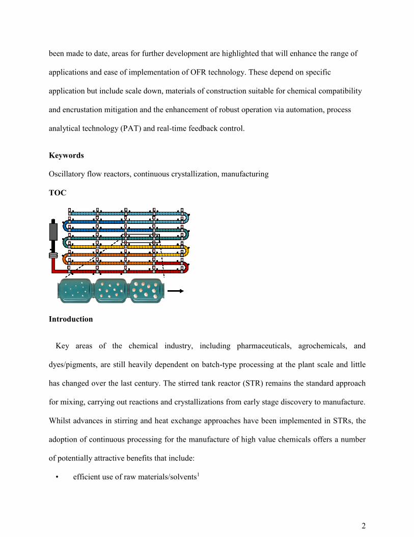
TOC
Introduction
Key areas of the chemical industry, including pharmaceuticals, agrochemicals, and
dyes/pigments, are still heavily dependent on batch-type processing at the plant scale and little
has changed over the last century. The stirred tank reactor (STR) remains the standard approach
for mixing, carrying out reactions and crystallizations from early stage discovery to manufacture.
Whilst advances in stirring and heat exchange approaches have been implemented in STRs, the
adoption of continuous processing for the manufacture of high value chemicals offers a number
of potentially attractive benefits that include:
• efficient use of raw materials/solvents1

3
• minimization of waste/disposal1
• improved yield/conversion2,3
• improved rate/process reliability in addition to enhancing chemical reactions which may
have otherwise been limited in a batch-type setup4,5
• improved heat/mass transfer with particular suitability towards varying bulk physical
forms which exist for specific processes6,7
• reductions in energy consumption for running processes in addition to reactor downtime
for maintenance and cleaning8,9
• efficient use of physical plant space1
• significant reduction in process development required for scale up operations10,11
• improved handling of hazardous materials including dangerous and/or unstable
intermediates12,13
The pharmaceutical industry in particular can benefit enormously from the benefits of
continuous manufacturing (CM)14,15 and the availability of microfluidic16 and mini/mesofluidic
reactors which may be used on laboratory and pilot plant scales for development of synthetic
processes in particular, provide opportunities to develop and implement continuous
processing.17,18 Reaction parameters such as temperature, concentration and composition of
reactants established for a small scale flow process can be directly scaled-up or scaled-out. In
contrast, analogous batch-type processes often require significant scale-up design and
optimization involving numerous parameters including heat and mass transfer, impeller type and
vessel geometry.
In recent years the potential for fully integrated end-to-end CM of pharmaceuticals has been
demonstrated for alikserin hemifumarate19 with all stages from synthesis to final product
manufacture carried out in a multi-stage plant that implemented a plant-wide control

4
approach.20,21 However there is still a need for further feasibility studies that include assessments
of the economical benefits of CM in comparison with batch. It is also worth noting that CM is
not the best choice for every process; this is dictated by the inherent kinetic parameters and
physical properties of the process. It is also important to note the potential impact of CM on the
existing supply chain.22,23 Whilst there has been a significant rise in flow chemistry research in
recent years,24 for CM to be adopted there is also a need for reactors that can support other
operations in continuous mode including work-up, crystallization, filtration, isolation and drying.
This review article presents an overview of one technology that is suitable for continuous
crystallization processes and covers the general operating principles, considerations for
implementation of crystallization, and further requirements.
Crystallization
Crystallization is a complex, multi-phase unit operation used in a wide range of manufacturing
industries to achieve separation and purification of products.25,26 There are various approaches
including reactive, evaporative, anti-solvent and cooling crystallization which can be applied
depending on the needs of the process. Whichever approach is implemented, delivering control
over product purity is critical. Other important targets are yield and particle attributes including
size, shape and physical form of crystals. For example, the crystal size distribution (CSD) is
commonly used as a critical quality attribute (CQA) and relatively large (e.g. 100 – 500 µm),
high quality crystals, which can be reproduced consistently, are typically desired for industrial
crystallization processes. Several factors contribute to the final CSD including primary27 and
secondary28 nucleation, growth, agglomeration, attrition and crystal breakage, encrustation,
disturbances to the metastable zone width (MSZW,26,27,29 see Figure 1) such as an impurity
profile, polymorphism, agglomeration/aggregation, solvates and hydrates and seeding.

5
Figure 1. Phase diagram highlighting the supersaturated, saturated and stable undersaturated
regions. The MSZW is also shown. The dark, solid line represents a temperature dependent
solubility curve.
Conventional approaches for obtaining crystals of a desired crystal form and size distribution
have suffered from batch-to-batch variability, particularly at the manufacturing scale. There has
been an increasing interest for the pharmaceutical industry in quality-by-design (QbD)
approaches28,30 in order to tackle such variability. Process cost reductions and maximizing
operation efficiency are key drivers for exploring these methodologies. Continuous
crystallization is an attractive approach for operating via QbD approaches. In addition to the
general continuous processing advantages, it offers enhanced control of the physical properties
of the crystalline mass.31 Following a start-up period,32,33 when a continuous crystallizer is
operated under a controlled steady state, the crystallization process in theory behaves under
uniform conditions with no variability in temperature, concentration, CSD etc over time leading
to greater reproducibility when compared with batch methods. Narrower CSDs obtained directly
from crystallization can eliminate the need for further corrective processing such as milling

6
(highly energy intensive) and have a significant impact on secondary, downstream processes
including filtration, drying and subsequent formulation. Furthermore, the control of polymorphic
form is an important challenge and the delivery of continuous, consistent process conditions is
much more favorable for this purpose.34 As such there is considerable interest in technologies
and approaches that can deliver robust, well controlled continuous crystallization processes.
A number of continuous crystallizer designs are currently in use in the chemical industry, see
Table 1, although it is noteworthy that these have been significantly less applied for
pharmaceuticals/fine chemicals. This may be because many of the advantages of continuous
processing are only brought to light when the volumes produced are very large (i.e. commodity
chemicals) and most pharmaceuticals compound volumes are relatively low in comparison hence
the economic/cycle time drivers are not perceived to be there. In terms of platforms, mixed
suspension mixed product removal (MSMPR) setups with single and multiple stages and plug-
flow reactors (PFRs) are the most commonly featured. The kinetics of the process should
determine platform selection: faster processes with short residence times are favored for PFRs
and MSMPR cascades are generally adopted for slower processes requiring longer residence
times. In general the principals of PFRs vs MSMPRs have been described elsewhere.35-39 A
typical objective of a series or cascade operation is to economize on heat utilization, e.g. by
dividing the overall temperature gradient over several stages and operating each stage at a lower
temperature to drive supersaturation. Furthermore, in a cooling crystallization, due to the less
extreme temperature drops required across the heat exchange elements, encrustation problems
may be significantly reduced. This is a key point as encrustation (defined as the unwanted
deposition of solids on a surface) is generally considered the principal reason for disrupting the
controlled steady state operation of a continuous crystallizer.
7
Table 1. Selected literature highlighting various compounds which have been applied for
continuous crystallization.
MSMPR (single stage) MSMPR cascade Plug-flow
melamine phosphate 40 Aliskiren hemifumarate41 α-lipoic acid-nicotinamide42
paracetamol43 cyclosporine44 industrial API35
magnesium ammonium
phosphate45
pharmaceutical intermediate46 ketoconazole, flufenamic acid, L-
glutamic acid47
sodium bicarbonate48
calcium carbonate49
Deferasirox50
benzoic acid51
benzoic acid51
acetylsalicylic acid52
adipic acid53
salicylic acid54
cyclosporine55
ascorbic acid56
lactose57
sugar58
calcium carbonate59
L-glutamic acid60,61
potassium sulfate62
MSMPRs remain the most utilized platform for continuous crystallization largely due to
familiarity in terms of operation and control. These have also been successfully operated at
various scales however they pose numerous disadvantages for the application of crystallization
including high localized shear regions due to agitators, non-uniform temperature control,
challenges with handling solids at transfer lines and non-linear scalability. PFRs offer advantages

8
in each of these challenges and as a result are interesting platforms for applying continuous
crystallization.
History of oscillatory flow reactors
An oscillatory flow reactor (OFR) is a particular type of tubular reactor which has drawn
increasing attention over the past few decades.63-66 It comprises a tubular device containing
periodically spaced restrictions (these are commonly orifice baffles although additional types
have been investigated)67,68 superimposed with oscillatory motion of a fluid. Mixing is provided
by the generation and cessation of eddies when flow interacts with the restrictions and with
repeating cycles of vortices, strong radial motions are created, giving uniform mixing in each
inter-restriction zone and cumulatively along the length of the tube,69 see Figure 2. The
generation and cessation of eddies has proved to result into significant enhancement in processes
such as heat70,71 and mass72-74 transfer, particle mixing and separation,75 liquid-liquid reaction,76
polymerization,77,78 flocculation79 and crystallization, which will be discussed further within this
review. Research has been further extended to include flow patterns,80-82 local velocity profiles
and shear rate distribution,83 residence time distribution (RTD),81,82,84,85 dispersion,86-88 velocity
profiles89 and scale-up operations.90
Figure 2. OFR section highlighting fluid mixing on interaction with the equally spaced
restrictions. The circular arrows represent idealized fluid flow conditions. In this schematic,
oscillation is shown to be provided by a piston.
9
Whilst this review is fundamentally focused on OFR technology as a platform for continuous
crystallization, it was necessary to gather existing literature for additional applications, in order
to clearly establish the design rules for construction, operation and scaling. Additionally, the
determination of which factors for a given process (be it physical parameters such as density,
viscosity, solid loading or kinetic information such as nucleation and growth rates) indicate
suitability for implementation into a given OFR system. Traditional crystallization platforms
such as MSMPRs or more bespoke platforms such as segmented tubular flow reactors
(STFRs)52,91 or agitated tube reactors (ATRs)92 may indeed be more appropriate. For example, an
OFR may not be able to provide sufficient residence time, the solids loading may be impractical
or there may be specific issues with materials of construction. Microreactors (tube diameters of
10 - 500 µm) have received a huge level of interest recently for chemical reactions in flow but
are generally less considered for crystallization due to solid handling challenges. This review of
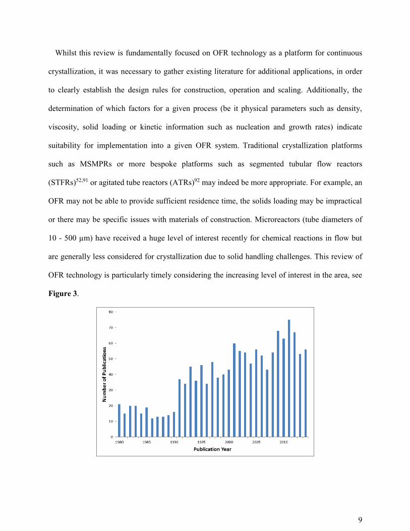
OFR technology is particularly timely considering the increasing level of interest in the area, see
Figure 3.

10
Figure 3. Graph highlighting the increasing level of interest in oscillatory flow reactors. This
was generated from Web of ScienceTM using keywords ‘oscillatory flow’ and covers a time
period from 1980 - 2014.
The general principles associated with OFRs were initially established by Van Dijck in 193593
and until the early 1980s, reciprocating plate columns (RPCs)94,95 and pulsed packed columns
(PPCs)96-99 were the only significant unit operations exploiting the benefits of oscillatory flow
mixing, specifically enhanced heat and mass transfer capabilities. Since the 1980s, a number of
research groups, and additionally, an increasing number of industrialists, have shown an interest
in oscillatory flow reactors due to the highly organized fluid mixing conditions when oscillation
is applied.
There are essentially two modes of operation for oscillatory mixing: periodic motion of the
intrinsic elements (i.e. moving baffle (MB) or plates) within the column100-103 or periodic motion
of the fluid where the internal elements are fixed.102,104 These fixed internal constrictions may be
inserts which remain stationary or can be engineered within the tubing, a common example being
a fully constructed glass system. Examples are displayed in Figure 4. For moving fluid (MF)
setups an oscillating piston may be used where a plug is coupled to the base of the column.105
The constrictions are typically spaced at a uniform distance apart and generally, the constriction
diameter, d0, equates to around half the value of the tube diameter.

11
Figure 4. Examples of oscillating platforms. Left: moving baffle (MB)101 and right: moving fluid
(MF).104
The most useful, niche application of the OFR has been the conversion of inherently slow
reactions from batch to continuous mode with greatly reduced length to diameter ratios
(compared to conventional PFRs). Additional advantages have been described including good
handling of solids and slurries, enhanced heat and mass transfer capabilities, linear scalability,
minimal concentration gradients and facile implementation of process analytical technology
(PAT).106 Limitations have been identified as low tolerance for gaseous species, fluid viscosity
and particle density limits, and a threshold for solid concentration. These points will be discussed
throughout this review. It should be noted that alternative terminology can often be found in the
literature: pulsed flow reactors (PuFRs), oscillatory baffled columns (OBCls), oscillatory baffled
crystallizers (OBCs) or oscillatory baffled reactors (OBRs). Ni65 and Abbot63 have previously
presented reviews on the applications of oscillatory flow technology, the contribution by Ni in
2003 summarizing the concepts and key developments of OFR enhancement and by Abbot in

12
2013, with a specific focus on biological processing. McDonough has also reviewed mesoscale
OFRs for rapid process development.107 There have also been numerous PhD theses dedicated to
the subject.87,108,109
OFR operating principles
Whilst conventional tubular reactors rely on a high throughput velocity to achieve mixing i.e.
obtaining the net velocity to achieve a high enough Reynolds number (Re, defined below for an
STR and pipe in Equations 1 and 2) potentially resulting in excessive tube lengths to
accommodate long residence times, an OFR system does not. In this case, the flow conditions are
governed by the effect of the oscillations. The periodically reversing fluid motion which interacts
with the baffles forms strong toroidal vortices, hence allowing lower net flow velocity and
shorter tubing lengths in addition to lower working volumes when compared to conventional
systems. In Equations 1 and 2, ReSTR is the Reynolds number for a stirred tank reactor, Repipe is
the Reynolds number for flow through a tube, N is the impeller speed, Dimp is the agitator
diameter, ρ is the fluid density, µ is the dynamic viscosity, u is the net flow velocity and d is the
tube diameter.
𝑅𝑒𝑆𝑇𝑅 =𝜌𝑁𝐷𝑖𝑚𝑝
2
𝜇 (𝟏) 𝑅𝑒𝑝𝑖𝑝𝑒 =
𝜌𝑢𝑑
𝜇 (𝟐)
Operating under plug-flow conditions means that the residence time in a given reactor is the
same for all elements of the fluid, see Figure 5. Plug-flow is defined as an orderly flow of fluid
through a reactor and the key aspects are (i) no overtaking fluid elements in the direction of flow,
(ii) perfect mixing in the radial direction and (iii) that all flow elements reside for the same
length of time. This has been related to crystallization via various modelling approaches.47,110-112
Traditionally, near plug-flow conditions have been achieved using a series of MSMPRs with the
theory that plug-flow is achieved when the number of reactors approaches infinite. The

13
disadvantages of this include higher overall running costs, a lack of temperature control for
transfer lines (although this can be addressed to some extent) and, specifically for crystallization
reactions, particles may be broken up or retained within pumps causing undesirable nucleation
events and blockages. Near plug-flow conditions have also been obtained by operating a tubular
reactor at turbulent flow, the major disadvantage being the need for significantly high flow rates
(short residence times) leading to very long reactors and large capital costs.
Figure 5. Illustration of laminar, turbulent and plug-flow.
The unique mixing effect generated by oscillation is generally achieved across typical ranges
of 0.5 - 20 Hz (frequency, f) and 1 - 100 mm (center-to-peak amplitude, x0). The MB approach
tends to be limited to batch-type setups whereas MF is adopted for both batch and continuous.
Changing the combination of f and x0 allows control of the generation of eddies and produces a
range of fluid mechanical conditions as broad as required.69,113,114 For continuous operation, the
oscillation can be generated at one or both ends of the column using bellows, pistons or
diaphragms.
When considering continuous operation, the system should be operated such that the maximum
oscillatory velocity is at least double the net velocity of the fluid flowing through the tube. This
means that the flow is always fully reversing with the fluid interaction at the constrictions. The
mixing generated in the zones between successive constrictions is then uniform, and the tube
itself can behave as a series of well mixed stirred tanks. Importantly, mixing is independent of

14
the throughput velocity meaning it is possible to have a low net flow velocity (corresponding to
nominal laminar regime in the absence of oscillations), but maintain good mixing and plug-flow
performance through control of the oscillatory conditions.
Various approaches for imposing periodic constrictions in an OFR have been reported in the
literature including single and multi-orifice baffles and smooth periodic constrictions (SPCs).
Single orifice baffles are the most commonly encountered at various scales whereas the SPC
systems are a more recent development and are mainly limited to mesoscale platforms with the
exception of one study.115 These will be discussed in detail later on. Multi-orifice systems have
been shown to exhibit a higher degree of similarity in terms of shear rates and mixing intensity
when scaling up in comparison to single orifice platforms.67,68,116 The presence of SPCs as
opposed to ‘sharp-edge’ baffles has been shown to minimize high shear regions and maximize
mixing efficiency with the elimination of ‘dead-zones’ in which particles may sediment or
become trapped.117

15
Figure 6. Schematic illustrating the various approaches in the literature for imposing
constrictions in an OFR. Top: single orifice baffle designs, middle: smooth periodic constrictions
(SPCs) and bottom: multi-orifice baffle designs. The equations for calculating the baffle open
cross sectional area, α, baffle spacing, L, and effective tube diameter, de are also shown.
The constriction spacing, L, is normally within the range of 1 - 3 times the tube diameter, with
a distance of 1.5 d being the most common due to interpretation of flow visualization
photographs by Brunold80 for effective mixing over a wide range of f and x0. Ni later identified L
= 1.8 d as an optimal spacing based on a mass transfer study.90 Different values of L will result in
different flow behaviors as the shape and length of the eddies are influenced within each
constriction cavity.118 Mackley used a new dimensionless group called the stroke ratio intending
to classify the flow in terms of the relation between oscillation amplitude and L.119 The optimal L
should ensure a full expansion of vortex rings generated behind constrictions so that vortices will
spread effectively throughout the entire inter-constriction zone. At a small value of L the
generation of vortices is strongly suppressed. This effectively restrains the growth of vortices and
reduces the required radial motion within each constriction cell. If the constrictions are spaced
too far apart, the vortices formed behind the constrictions cannot effectively cover the entire inter
constriction regions. Stagnant plugs in which vortices will disperse and diminish.
The baffle open cross sectional area, α, is normally chosen within a range of 10 - 50 % based
on a compromise between minimizing frictional losses and maximizing the mixing effect.
Various studies77,114 have been carried out in attempt to optimize this parameter including a
systematic investigation by Gough69 for polymerization suspension mixing. At lower values ~26
% small symmetrical eddies were formed at the sharp edges of the baffles and the vortex rings
did not encompass the entire column cross section nor the complete length of the entire baffle

16
region, thus stagnant regions between eddies were identified. Increasing to ~32 %, eddies
extended to the reactor walls covering a greater area of the section. Vortex rings were still
symmetrical along the center line (axi-symmetric) and displaying small interaction. Increasing to
40 % the axi-symmetry was lost and the intense interaction between eddies led to the
disappearance of the stagnant regions within the baffled cavity – inducing plug-flow
characteristics desirable for continuous operation. At the highest values ~47 %, a large degree of
channeling through the baffle orifice was observed and the formation of eddies was destroyed by
the predominant axial movement, thus low mixing took place.
In terms of scaling between OFR systems, L and α (Figure 6) are crucial parameters which
must be kept constant in order to minimize any process development scale up issues, as these
factors control the size and shape of the resultant mixing vortices.120 They are calculated via
Equations 3 and 4. Note that an effective tube diameter term, de, is used for multi-orifice
systems.109
𝐿 = 1.5 𝑑 (𝟑) 𝛼 = (𝑑0
𝑑𝑒)
2
(𝟒) 𝑑𝑒 = √𝑑2
𝑛𝑜 (𝟓)
In general, the overall fluid mechanical conditions of an OFR are governed by two
dimensionless quantities,121 namely the oscillatory Reynolds number, Re0 and the Strouhal
number, St, as shown in Equations 6 and 7 below:
𝑅𝑒0 =2𝜋𝑓𝑥0𝜌𝑑𝑒
𝜇 (𝟔) 𝑆𝑡 =
𝑑𝑒
4𝜋𝑥0 (𝟕)
Re0 describes the intensity of mixing applied to the tube, where 2πfx0 equates to the maximum
oscillatory velocity (ms-1), and St is the ratio of column diameter to stroke length (or amplitude),
measuring effective eddy propagation inside the baffle cavities.80,121-124 St is inversely
proportional to x0 and if too high, causes eddies to be propagated into the adjacent cavities. In

17
contrast to steady flows in pipes, where the transition to turbulence begins at around Re = 2000,
flow separation in oscillatory flows occurs for values of Re0 of the order 50.125 At low Re0 = 100
– 300 the system exhibits plug-flow characteristics where vortices are axi-symmetrically
generated within each baffled cavity. This is generally known as a soft mixing regime. When Re0
is increased further symmetry is broken and flow becomes intensely mixed and chaotic, i.e. more
turbulent like.78,126 The net flow Reynolds number, Ren, analogous to Repipe but with u
representing a superficial net flow velocity, can be calculated via Equation 8 as follows:
𝑅𝑒𝑛 =𝜌𝑢𝑑
𝜇 (𝟖)
Ren is fixed by u and Re0 is fixed by the intensity of oscillation. There is little advantage in
using oscillatory flow if Ren > 250 as the effects of net flow become significant and the benefits
of operating at laminar flow rates diminish.125 The calculation of Ren allows a velocity ratio, ψ to
be determined via Equation 9:
𝜓 =𝑅𝑒0
𝑅𝑒𝑛 (𝟗)
This ratio should be greater than 1 so that the maximum oscillation velocity is always higher
than the net flow velocity through the tube, however values in the range of 2 - 10 have been
recommended for plug-flow operation.66 It should be noted that these values have only been
validated for liquids as opposed to multi-phase systems such as slurries. A major property of
oscillatory flow mixing is that secondary flow (i.e. flow reversing) occurs only in the vicinity of
tube constrictions. As a consequence, the fluid back-mixing127 generated by the oscillatory
movement of the fluid in the plain sections of the tube should be negligible. An approach for
continuous operation therefore would be to fix the flow velocity, i.e. the fluid rate being pumped
through the tube, hence securing the residence time for a given tube size and length, and

18
subsequently choosing the oscillatory conditions such that Re0 > Ren (ψ > 1) meaning that the
superimposed oscillations will dominate the mixing regime. It should be noted that minimum
values for Ren and Re0 of 50 and 100 respectively have been postulated for sufficient mixing.66
OFR systems are often compared to STR ‘equivalents’ considering power density values, P/V
(W m-3), i.e. the amount of power applied per unit volume for each system. Power density values
have been typically used when scaling between STR setups and for an STR this is defined via
Equation 10 as:
𝑃
𝑉=
𝑃0𝜌𝑁3𝐷𝑖𝑚𝑝5
𝑉𝐿 (𝟏𝟎)
P0 is the power number, Dimp is the impeller diameter and VL is the volume of liquid in the
STR. P0 can be calculated128 or derived from plots generated by agitator suppliers and is
dependent on ReSTR. There are normally corrections applied for variations such as agitator,
baffling and reactor type.
There are essentially two models for estimating the power density in an OFR: the quasi-steady
flow model129 and the eddy acoustic model.130 The power input for the eddy acoustic model is
justified for conditions of low x0 and high f e.g. 1 - 5 mm, 3 - 14 Hz. This can be calculated using
Equation 11 where le is defined as the mixing length for the eddy enhancement model.
𝑃
𝑉=
1.5(2𝜋𝑓)3𝑥02𝑙𝑒
𝐿𝛼 (𝟏𝟏)
The quasi-steady flow model was originally derived for packed columns and subsequently
used for pulsed columns.131 The power input for this model is valid for higher x0 and lower f
values e.g. 5 - 30 mm, 0.5 - 2 Hz and can be estimated from Equation 12 below.
𝑃
𝑉=
2𝜌𝑁𝑏
3𝜋𝐶𝐷2 (
1 − 𝛼2
𝛼2) 𝑥0
3(2𝜋𝑓)3 (𝟏𝟐)

19
Nb is the number of baffles per unit length of tube and CD is the coefficient of discharge of the
baffles (directly related to the orifice in the baffle and has a normal value of 0.7).
An OFR offers enhanced heat transfer capabilities when compared to conventional tubular
systems as the presence of oscillation and baffles impacts a significant change in the fluid
mechanical conditions. When considering, for example a cooling crystallization process, one
could envisage significant benefits in terms of heat exchange whilst at the same time maximizing
energy efficiency. For a shell and tube heat exchanger (i.e. jacketed tube), where a fixed mass of
fluid in the tube is cooled or heated by the flow of a fluid of given temperature through the shell,
the tube-side Nusselt number, Nu, can be calculated via Equation 13:
𝑁𝑢 =ℎ𝑡𝑑
𝑘 (𝟏𝟑)
k is the thermal conductivity of the fluid and ht is the tube-side heat transfer coefficient. Many
additional factors have to be considered including the thermal conductivity of the tube wall
material, the outer tube diameter, the specific heat capacity of the fluid, flow rates, the total area
for heat transfer as a function of the tube diameter and (if applicable) any encrustation
implications. Various studies have been completed demonstrating enhancement of Nu values via
comparisons of unbaffled and baffled systems in addition to the presence and absence of
oscillations.70,71 The effects of Re0 have also been reported (see Figure 7) and the heat transfer
rate shown to be strongly dependent on the product of f and x0. Furthermore, comparisons have
been made between MB and MF systems132 illustrating that for both oscillatory configurations
the heat transfer performance at minimum matched that of a turbulent pipe whilst being able to
operate in laminar flow regimes.

20
Figure 7. Diagram illustrating heat transfer enhancement in an OFR. Reproduced with
permission from reference 65. Copyright 2003 Elsevier.
Improved mass transfer is often described for OFR systems when considering alternative
mixing devices such as STRs.73 This has been studied primarily via gas-liquid
investigations131,133-135 (although alternative approaches have been described)136 and the mass
transfer of gas into liquids is normally quantified using kLa, the volumetric mass transfer
coefficient that describes the efficiency of this transfer. Comparisons have been made in the
presence and absence of baffles and oscillations, improved gas hold up and contacting has been
observed for various baffle designs, and power density correlations have illustrated advantages in
mass transfer for OFR systems in comparison to STR setups due to improved shear rate
distributions.73 Mass transfer enhancement has also been shown to be strongly dependent on the
specific f and x0 conditions and interestingly, linear scale up as a function of mass transfer has
been demonstrated for batch OFR platforms.90 Further studies have included investigations at

21
various fluid viscosities137 and the demonstration of mass transfer enhancement with multi-
orifice platforms compared to single orifice.116
With the rapid advancement of computational fluid dynamics (CFD) modelling, studying the
flow and transport phenomena in an OFR has become feasible. Furthermore, these CFD models
have often been used in conjunction with particle imaging velocimetry (PIV) resulting in a
powerful approach towards characterizing the fluid mechanics of the system. Early
studies87,123,138-140 revealed that the vortex mixing mechanism was responsible for the high
mixing efficiency of the system and predictions of the onset of chaotic motions and
concentration gradients were evaluated by incorporating transport such as heat and mass transfer
and provided fluid-particle motion simulations.81,141,142 As mixing eddies have been shown to be
the essential enhancer, large eddy simulations (LESs)67,143,144 have been particularly suited for
studying flow in an OFR and the effects of f and x0 have been investigated.
The flow characteristics of oscillatory flow are dominated by the axial velocity components
(see Figure 8) but with numerical studies there is now good understanding of the nature of the
mixing.145-149 At Re0 = 100 - 300, the OFR exhibits good plug-flow characteristics where the
vortices are axi-symmetrically generated within each baffled cavity (referred to as plug-flow
mode). For higher Re0 values the generation of vortices is no longer axi-symmetrical and the
flow becomes intensely mixed and chaotic (referred to as the mixing mode). Depending on
column geometry and viscosity these critical values may vary.150
Figure 8. Illustration of axial and radial dispersion for flow within a tubular system.

22
As the oscillatory motion is periodic and fully reversing, there are two half cycles, each
containing flow acceleration and deceleration corresponding to a sinusoidal velocity-time
function. On each flow acceleration, vortex rings form downstream of the baffles. A peak
velocity is reached, and then as the flow decelerates, the vortices are swept into the bulk, and
subsequently unravelled with the bulk flow acceleration in the opposite (axial) direction. It is the
strong radial velocities, arising from the repeating cycles of vortex formation and of similar
magnitude to the axial velocities, that give uniform mixing151 in each inter-baffle zone and
cumulatively along the length of the column.
Various CFD studies have been reported including comparisons with baffled and unbaffled
systems illustrating the challenges in achieving efficient radial mixing at low flow rates.152-154
Comparisons of MB and MF systems have also been performed,155 in addition to scaling studies
between OFRs.156 Simulations incorporating oscillatory flow highlighted an efficient way of
generating well mixed flows with low axial dispersion, good global mixing with high shear rates
at the walls and hence a near plug-flow residence time distribution (RTD) is achievable at Ren
values as low as 80.154 Furthermore, CFD models in conjunction with PIV have been used to
correlate strain rate with the power dissipation generated within OFRs and lower strain rates
were calculated for OFRs in comparison to STRs at similar power density values.83,157
Comparative experiments have shown that volume averaged shear rates for OFRs are an order of
magnitude larger than that of an STR and particles in an OFR spend most of their residence time
in high shear regions.
In general, the way in which RTD can be affected by manipulation of the mixing conditions is
fundamental to the operation of a reactor.158 For OFRs the RTD performance can be affected
independently of the net flow conditions, i.e. very sharp (or near plug-flow) RTD measurements

23
can be achieved at moderately low Ren values as a result of radial velocity components being of
comparable magnitude to the axial velocities in a tubular system.159,160 The axial dispersion
coefficient, D is used to describe the characteristics of mixing in tubular setups. It is a measure of
the degree of deviation in flows from the true plug-flow scenario: in theory D should be zero for
plug-flow. Equation 14 shows a species material balance subject to transport by convection and
axial dispersion in a one dimensional continuous system:
𝛿𝑐
𝛿𝑡= 𝐷
𝛿2𝑐
𝛿2𝑥− 𝑢
𝛿𝑐
𝛿𝑥 (𝟏𝟒)
c is the concentration of the species, t is the time and x is the position along the axial length
Three types of model have been used in the literature161 to study RTD in an OFR: a dispersion
model-type where the reactor is seen as a one dimensional continuous path, a compartmental
(tanks-in-series) model-type in which the reactor is considered as being divided into well-mixed
discrete stages and a tanks-in-series incorporating back-mixing. The concept of an ‘ideal’ STR
assumes the composition of fluid leaving the tank is equal to the average composition within the
tank. The tanks-in-series model considers each inter-baffle zone as an STR and the model
assumes the concentration-time response can be represented by a cascade of equal size, ‘ideal’
STRs in series which gives the best fit to the concentration-time data. When the deviation from
plug-flow is small, the dimensionless axial dispersion coefficient term36 (or inverse Peclet
number), D/ul can be related to the number of stirred tanks in series, n, via Equation 15:
𝐷
𝑢𝑙=
1
2𝑛 (𝟏𝟓)
l is the length of the tubular vessel. Ideally, a continuous OFR (COFR) should be operated at
an x0 value that gives the minimum D/ul. Considering a large number of continuous stirred tanks
in series, with net flow and an overall plug-flow response, such a system may be of great benefit
24
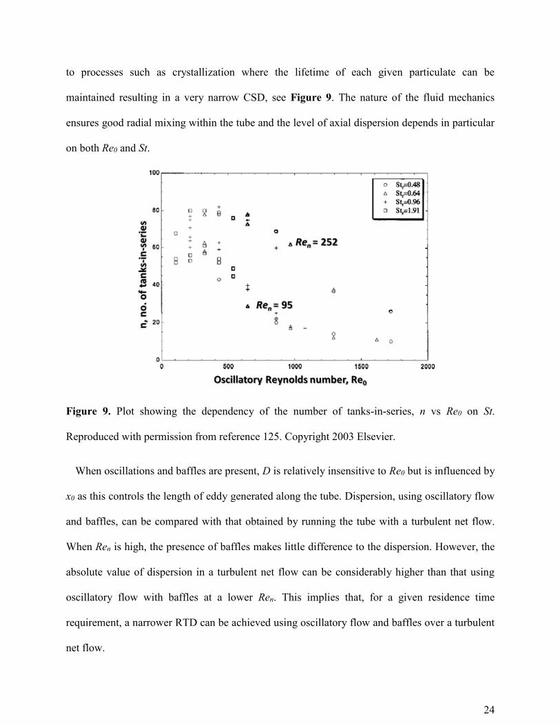
to processes such as crystallization where the lifetime of each given particulate can be
maintained resulting in a very narrow CSD, see Figure 9. The nature of the fluid mechanics
ensures good radial mixing within the tube and the level of axial dispersion depends in particular
on both Re0 and St.
Figure 9. Plot showing the dependency of the number of tanks-in-series, n vs Re0 on St.
Reproduced with permission from reference 125. Copyright 2003 Elsevier.
When oscillations and baffles are present, D is relatively insensitive to Re0 but is influenced by
x0 as this controls the length of eddy generated along the tube. Dispersion, using oscillatory flow
and baffles, can be compared with that obtained by running the tube with a turbulent net flow.
When Ren is high, the presence of baffles makes little difference to the dispersion. However, the
absolute value of dispersion in a turbulent net flow can be considerably higher than that using
oscillatory flow with baffles at a lower Ren. This implies that, for a given residence time
requirement, a narrower RTD can be achieved using oscillatory flow and baffles over a turbulent
net flow.

25
Experimental RTD studies for various OFR systems have been reported via tracer
injections84,162 (although alternative approaches have been considered)163 and monitoring some
response as a function of time. An imperfect pulse correction can be applied to the modelling
approaches in order to incorporate experimental technique.81,82,85,88 The effect of tracer density
has also been investigated.126 The application of oscillation has a significant impact on the RTD
of a given system; an absence of oscillation results in concentration curves typical of those
observed for laminar flow in a tube e.g. a sharp breakthrough followed by a decay curve with a
long tail corresponding to the arrival of fluid elements that have travelled in different radial
positions and consequently have moved through the tube with velocities less than the centreline
peak velocity. We have performed numerous RTD characterisations on COFR systems, the
details of which are published elsewhere,164 in order to identify the level of deviation from plug-
flow operation, see Figure 10. This specific example is for a 15 mm COFR system with an
aqueous medium and tracer injection modelled with the Levenspiel perfect pulse model. An
optimal RTD response can be observed from various oscillatory and net flow conditions.

26
Figure 10. Plot showing tracer concentration as a function of dimensionless time as predicted by
the perfect pulse model for various operating conditions of a COFR. An optimal region close to
plug-flow can be observed.
The effects of f and x0 on the RTD have also been investigated84 and in general x0 has a more
pronounced effect on the dispersion characteristics, see Figure 11. It has been shown that a
well-defined region for Re0 exists where the RTD is closest to plug-flow behaviour for any fixed
Ren and it was found that the velocity ratio in the range 2 < ψ < 4 corresponded to the optimal
RTD conditions being achieved.125 These dimensionless parameters are sufficient to select the
oscillatory conditions necessary to obtain an optimum RTD in an OFR based on a desired
throughput specification.
Figure 11. Graph of log dispersion D/ul as a function of log amplitude of oscillation.
Reproduced with permission from reference 84. Copyright 2003 Elsevier.
A summary of the desirable operating ranges for traditional OFRs is shown below in Table 2.

27
Table 2. Summary of the accepted ranges for Re0, St, Ren and ψ for traditional OFRs based on
the existing literature.
Re0 St Ren ψ
50 (flow separation occurs)125 < 0.1 (fast stream core, strong shear)149
> 50 (minimal value for convection i.e. sufficient mixing)66
> 1 (maximum oscillatory velocity higher than net flow66 velocity)
> 100 (minimal value for convection i.e. sufficient mixing)66
> 0.5 (effective eddy shedding)149
> 80 (rapid mixing and uniformity)142
2 - 4 (optimal RTD conditions)66
< 250 (flow 2-D, axi-symmetric, soft mixing regime)159
0.6 – 1.7 minimum axial dispersion coefficient, D84
> 250 (flow 3-D, no axi-symmetry, turbulent-like)159
Equipment
The application of OFR technology has increased in parallel with the development of suitable
equipment and robust platforms which are able to exploit the various advantages. Table 3
highlights a selection of patents (associated with crystallization) which have been filed
representing various technical advances.
Table 3. Summary of patents filed relevant to OFRs and crystallization.
Patent Summary Filing Date Inventor(s) Reference
Incrustation resistive crystallizer
Vibrating perforated plates for encrustation mitigation
Feb, 1984 Carter, Hsu EP 0119 978 A2
Oscillatory flow mixing reactor
Mixing for multiple phase systems
Feb, 2006
Gron, Schutte, Drauz, Stadtmüller, Grayson
US 2008/0316858 A1
Improved apparatus and method for temperature controlled processes
Controlled temperatures applied to a substance in different process zones
Nov, 2006 Ni, Laird, Liao
WO 2007060412 A1

28
Apparatus and process for producing crystals
COBC for crystallisation including ultrasound
Jan, 2010 Ruecroft, Burns
US 2011/0288060 A1
Crystallisation process and apparatus
Oscillatory based continuous crystallisation platform with automated control
Oct, 2010 Harji WO 2011051728
A1
Oscillating flow minireactor
Oscillating flow device with directional changes in a channelled pathway
Jan, 2011 Reintjens, Thathagar
US 2014/0081038 A1
Device for inducing nucleation
Surface abrader configured to induce crystal nucleation within a vessel
Dec, 2012 Ni, Callahan WO 2013088145
A1
The majority of early studies featured batch-type OFR setups for various applications
including bio-105,165,166 and chemical reactions,76 polymerization,78,167,168 photo-catalysis,169-171
flocculation,79,172 gas-liquid contacting,173 phase-transfer catalysis (PTC),174 hydrate formation175
and mitigation of wax deposition.176 For polymerization applications, some interesting
correlations have been made between droplet size (as a function of f and x0) and the polymer
particles.104 There has been significant interest in OFR platforms for biological applications and
process intensification177 i.e. the development of novel apparatus and techniques to bring
dramatic improvements in manufacturing and processing, substantially decreasing equipment
size/production capacity ratio, energy consumption, or waste production. Additionally, while the
majority of these applications involved a single orifice baffle design, alternative approaches have
also been considered.178
The OFR has also been examined for continuous applications, see Figure 12. Ni used a 25 m
glass system (d = 40 mm) to evaluate droplet size distributions (DSDs) of oil/water mixtures
over a range of f and x0 values.179-181 Stonestreet evaluated a pilot scale stainless steel OFR of 2.9
m (d = 24 mm) length as a method for continuous production of sterols in an ester saponification
reaction.182 The COFR achieved the required product specification, in a residence time one
eighth that of a full scale batch reactor. Harvey used a 3 m (d = 25 mm) glass COFR to

29
investigate the trans-esterification of natural oils to form biodiesel in a process intensification
trial.183 It was demonstrated that a suitable conversion could be achieved in a residence time
substantially lower than that of batch processes. Vilar used a glass 5 m (d = 50 mm) COFR to
study oil/water emulsions with electrical impedance tomography (EIT) as an on-line analytical
tool.184 This allowed concentration mapping and the measurement of velocity distributions in
two-phase flows, where electrical conductivity or permeability differences exist between the
two-phase fluids. Very recently, Lobry utilized a 5 m glass COBR (d = 15 mm) for liquid –
liquid dispersion towards suspension polymerization of vinyl acetate.185
Figure 12. Schematic of a continuous OFR setup.
Within the last decade there has been significant development in mesoscale OFRs117 for the
scaling down of processes. These have been designed to be scalable towards industrial
application directly or to be used as independent, small scale production platforms. A critical
difference between these systems and conventional OFRs, in addition to the smaller working
tube diameter, is the presence of SPCs as opposed to ‘sharp-edge’ baffles. While conventional
30
OFRs are linearly scalable113,186 with respect to parameters L and α, the fluid mechanics at d < 10
mm are behaving differently and questions around solid loading are critical, particularly when
considering high throughput continuous operation. Interestingly, a minimal value of Ren was
found to be around 10 (equating to flow rates of less than 10 ml min-1 although lower flow rates
have been investigated) for these systems as compared to 50 for conventional OFRs66 potentially
allowing for considerable residence times to be achieved.
The fluid mechanics within a mesoscale OFR do have some similarities to those generated in
conventional OFRs, but with a decreased critical Re0 number of 100 for flow separation and
breakage of flow axi-symmetry which was found to be related to the smaller cross-free section of
the constrictions in the SPC geometry. Numerical simulations187 with a 2-D axi-symmetric
laminar model have matched the flow patterns within the SPC geometry for situations with small
interaction between fluid elements (axi-symmetric flow) while a 3D model (laminar or LES)187
was necessary to match the breakage of flow axi-symmetry observed for higher values of Re0.
The fluid mechanics in the mesoscale systems were also found to be more sensitive to x0 and this
has been mainly attributed to the differences in baffle geometries.
The effect of oscillatory flow in a mesoscale screening reactor with regards to RTD of the
liquid phase has been demonstrated using a reactor formed by several jacketed glass tubes, each
of length 35 cm (d = 4.4 mm) and a volume of ca. 4.5 ml.188 The SPCs were positioned with a
mean spacing of 13 mm (approximately 3 d) and a constriction length of 6 mm. The constriction
diameter was 1.6 mm, representing 13 % (α = 0.13) of the cross-sectional area. This is
considerably less than the 50 % cross-sectional area used in conventional OFRs (α = ca. 0.2).
The results of the study showed that the level of back-mixing was highly dependent on both f and
x0 (as with traditional OFRs) and x0 had a higher effect than f. This work has been extended

31
using a combination of PIV and CFD for evaluation and a correlation fitted to experimental data
has allowed an empirical approach for estimation of axial dispersion in the mesoscale system,187
see Figure 13. At optimal oscillation conditions (f = 12 Hz, x0 = 4 mm) the mixing observed at
larger scales could be reproduced at this smaller scale and interestingly, it was possible to keep
high concentrations (15 wt./wt. %) of small diameter polymer supported catalyst beads
suspended in the screening reactor whilst maintaining uniform fluid mixing. Importantly, the
oscillation conditions have been shown to exhibit a strong influence on the RTD at Ren < 10 and
little effect on the RTD curves at Ren > 25.189,190
Figure 13. Left: experimental normalized c-curve and dispersion model fitting by imperfect
injection method. Right: axial dispersion coefficient (D) as a function of Re0 for a fixed
oscillation frequency of 6 Hz. Reproduced with permission from reference 190. Copyright 2003
Elsevier.
The mesoscale OFR systems have been applied in numerous biological applications for batch
and continuous setups.191-193 Gas-liquid contacting experiments have been performed for mass
transfer investigations and up to a 2-fold increase in the kLa values reported for a 50 mm
conventional batch OFR were observed.194,195 Applications in catalysis,196,197 chemical

32
synthesis198 and nanoparticle formation199,200 have also been reported. Additionally, alternative
baffle designs have been investigated201-203 and some specific advantages have been described
for helical-type baffles as these generate a ‘swirling flow’ in addition to vortices which has
potential benefits in terms of heat transfer and encrustation mitigation.201,204 The helicity is also
particularly suited to solid-liquid systems as the design does not feature such pronounced
constrictions where particles can become lodged. Interestingly, it has been reported that plug-
flow behavior in these systems could be achieved over a much wider range of Re0 compared to
alternative designs,205,206 see Figure 14.
Figure 14. Dependence of RTD performances on velocity ratio (ψ) for a central baffled reactor
(left) and a helical baffled reactor (right). Reproduced with permission from references 201 and
205. Copyright 2003 Elsevier.
A summary of the desirable operating conditions for the mesoscale OFR systems is shown
below in Table 4.
Table 4. Summary of the accepted ranges for Re0, St, Ren and ψ for mesoscale COFRs based on
the existing literature.

33
Re0 St Ren ψ
< 100 (axi-symmetric laminar flow)187
0.1 (non axi-symmetric eddies)117
< 10 (oscillation conditions have a strong effect on RTD)201
>10 (axial dispersion little affected by net flow)190
> 100 (flow 3-D, no axi-symmetry, turbulent-like)187
0.35 (axi-symmetric eddies),117 minimum deviation from plug-flow
> 10 (minimal value for convection i.e. sufficient mixing)117
4 - 10 (best approximation to plug-flow)201
100 - 300 (minimal axial dispersion)190
Optimal values with alternative baffle designs201 including helical204,205 and low flow rates of 0.3 – 0.6 ml/min202
>25 (oscillation conditions have little effect on RTD)201
>300 (minimal effects on axial dispersion)190
Examples of crystallization in OFR platforms
To date there has been various examples in the literature where OFR technology has been
applied to crystallization processes. Crystal suspensions are relatively sensitive to mechanical
collisions or regions of high shear introduced by impeller blades as these lead to crystal breakage
or attrition. This is especially relevant when interested in obtaining crystals with desired particle
attributes. The attraction of a COBC, whilst operating at a controlled steady state and under
specified de-supersaturation conditions, is that each particle can in theory experience identical
conditions during the lifetime in the crystallizer, leading to a uniform and consistent product
flow at the end. In addition there are no impellers which can lead to attrition and undesired
secondary nucleation. The majority of the existing work has been focused on batch OBC
systems, either MF or MB, and comparisons have been made with STC platforms using
comparable power density values.
Various crystal systems have been investigated in batch OBC platforms including
paracetamol,86,207,208 LGA209-211 and sodium chlorate.101,212,213 These studies (largely cooling

34
crystallization) have included the effects of strain and shear on crystal suspensions and it is
evident that the hydrodynamic environment of oscillatory mixing offers significant advantages,
see Figure 15. Interestingly, narrower MSZWs were obtained in the MB batch OBC (compared
to an STC), most likely due to the mechanical interaction of the baffles and the vessel walls. This
effect was also observed using the achiral compound sodium chlorate.101 The polymorphic nature
of LGA has allowed useful studies in batch OBC platforms. In addition, the effects of mixing
intensity, seeding and composition of baffle material on LGA crystallization have also been
investigated. It has generally been shown that by controlling the process parameters, the desired
crystal polymorph could be obtained in the batch OBC.
Figure 15. SEM images of paracetamol crystals produced from a batch OBC setup.208 The OBC
(right) has been shown to exhibit a lower strain rate when compared to an STC (left).
Reproduced with permission from reference 208. Copyright 2003.
Batch OFRs have traditionally been used as screening platforms prior to continuous
experimentation for applications such as polymerization or chemical and biological processing as
this allows evaluation at manageable scales. These have also been used to some extent for
continuous crystallization evaluation35,42 however it is important to realize that optimization on
such platforms does not fully translate for such application. Nucleation promoting environments
such as moving baffles, pistons or bellows may provide potentially misleading information and

35
this must be taken into consideration. For illustration, we performed a qualitative MSZW study
using paracetamol in a water:isopropanol (60:40 wt./wt.) mixture using batch MB and MF OBC
platforms. Focused beam reflectance measurement (FBRM), a common, and expensive, in-line
monitoring technique for crystallization was used to detect the nucleation temperatures. It was
observed that the nucleation induction time for the MB OBC was significantly lower than the
MF OBC platform – almost as soon as the supersaturated region was entered, primary nucleation
took place, see Figure 16.
Figure 16. Comparison of MSZWs obtained for MF and MB OBC platforms using a
paracetamol/water/isopropanol system.
Overall the measurement of kinetic parameters such as MSZW, primary and secondary
nucleation and growth rates in a hydrodynamic environment which differs from intended
continuous operation will likely lead to discrepancies. It is important to define which information
can be obtained via batch methods in order to reliably inform continuous operation (e.g.
solubility, residence time, PAT calibrations) or alternatively development at small scale
continuous may be more suitable. To that end, we have developed an automated PAT enabled
batch MF OBC system for this purpose, the details of which will be published elsewhere.

36
MF batch OBCs have previously been applied for the determination of kinetic parameters
relevant to crystallization studies. Laser illuminated video (LIV) imaging has been used for
observing and quantifying the anti-solvent and cooling crystallization of paracetamol and this
allowed determination of growth kinetics non-intrusively.214-216 The determination of MSZW,
CSD and the effects of supersaturation and mixing were examined. It was found that the degree
of supersaturation had the most significant effect on the overall growth rates, followed closely by
the degree of mixing and then the rate of anti-solvent addition. Both MSZW and mean crystal
size were shown to decrease with increasing Re0 and it was demonstrated that the LIV technique
was as sensitive to nucleation events as FBRM. Very recently, the nucleation kinetics for the
cooling crystallization of adipic acid were investigated using Nývlt,217 Kubota218 and population
balance interpretations.219 Due to their linear assumptions, both the Nývlt and the Kubota
interpretations were found to be most accurate over a narrower range of cooling rates, whereas
the nonlinear nature of the population balance approach makes it accurate over a much wider
range.
The OBC has also been applied for continuous crystallization, see Figure 17. Ni demonstrated
successful crystallization of a model API in a glass COBC of length 25 m (d = 25 mm) with a
residence time of 12 min compared to a 9.5 h batch process.35 Recently we used a 25 m (d = 15
mm) glass COBC for the scale-up of a novel α-lipoic acid:nicotinamide co-crystal system.42 The
use a glass COBC (d = 15 mm) for the anti-solvent crystallization of salicylic acid with solute
concentration steady states maintained for >100 residence times has also been demonstrated.54
Extended operation for 6.25 h allowed the generation of ca. 1 kg of product material. While the
successful operation of these processes is highly encouraging for the application of continuous
crystallization, further research and development is still required for moving towards feasible

37
implementation in industrial applications. Increased automation, PAT and real-time feedback
control are important considerations under current investigation. It is also important to consider
the integration of continuous crystallization with other unit operations both up- and downstream.
Figure 17. Images of laboratory COBC systems.
One of the most important challenges associated with the operation of COBCs and also of
general reference to continuous crystallization itself is encrustation, see Figure 18. This
manifests itself as an unpredictable solid formation at internal equipment walls causing
disruption to steady state operation which can cause interference with heat transfer or PAT
measurements or even cause complete blockage of the system. Encrustation can be the result of
specific interactions between a given surface and molecule in addition to solvent dependency or
be the result of poor control of supersaturation. The generation of high levels of supersaturation
substantially beyond solubility will likely lead to nucleation on a surface as opposed to the bulk.
Physical mitigation approaches to encrustation have been reported including ultrasound,52
surface coatings220 and additives221 however crystal engineering strategies such as seeding,
temperature cycling or controlling primary nucleation via external intervention such as
ultrasound or laser induced nucleation may also be effective. Nagy et al.222 recently proposed a
mitigation strategy that relies on injection of pure solvent to dissolve an encrusted layer in a

38
continuous plug-flow crystallizer. Significant issues with encrustation should be flagged up early
during process design via batch evaluation or small scale continuous operation. If the problem is
not feasibly resolvable, this should inform the decision in considering a specific continuous
platform such as a COBC.
Figure 18. Images highlighting encrustation. Left: a PAT probe and right: a tubular section of a
COBC.
We specifically operated a continuously seeded crystallization process for LGA in a 25 m glass
COBC system (d = 15 mm).223 Attempting to operate the process without seeding led to
significant encrustation such that the crystallizer had to be shut down. However, by seeding with
β-LGA crystals and maintaining a bulk supersaturation below 3, the polymorphic phase purity of
the thermodynamically stable β-polymorph was retained allowing robust processing for at least
10 hours. Additionally, we performed a continuously seeded sonocrystallization of alpha-lactose
monohydrate in a 3.5 m, multi-orifice, polished stainless steel COBC (de = 69 mm).224 This
allowed a throughput of 356 g h-1 for 12 - 16 hours operation. Kinetic and thermodynamic
parameters were evaluated in a batch evaluation unit which provided a suitable mimic of the
mixing, hydrodynamics and operating conditions of the continuous platform whilst consuming
limited material. PAT including FBRM and mid-IR was implemented in both batch and
continuous experimentation in order to understand and monitor the process.

39
For both of these studies, continuous seeding was essential in allowing robust operation with
no evidence of encrustation leading to process disruption. As a result, suitable strategies for the
generation of seed streams must be considered in order to feed into the subsequent growth
process. We have developed a novel continuous anti-solvent nucleation unit which has been used
to produce paracetamol seed crystals with a narrow size distribution.225 The nucleation unit
operated at sufficiently high supersaturations and could be used to produce seed crystals with a
high degree of reproducibility.
An overall summary of the use of OBC technology for crystallization is shown below in Table
5.
Table 5. Summary of crystallization applications for the OBC system.
System Technique Batch /
Continuous Year Conclusion Reference
paracetamol Cooling Batch 2004, 2005, 2007
Improved crystal quality (CSD, surface, microstrain)
Ristic86,207,208
L-glutamic acid
Cooling, seeding
Batch 2004, 2008, 2009
Polymorph control, OBC promotes nucleation hence reduces MSZW, baffle MOC effects
Ni,209,210 Roberts211
Astrazeneca API
Cooling Batch and
Continuous 2009
Batch: faster cooling rates possible leading to desired crystal habit, improved CSDs. Continuous: residence time reduced from 9.5 h to 12 min
Ni35
paracetamol Cooling,
anti-solvent
Batch 2011 Laser illuminated video imaging used non-intrusively to evaluate MSZW, growth rates, CSD, mean crystal size
Ni214-216
sodium chlorate
Cooling, seeding
Batch 2012, 2014
Moving baffles promote unexpected nucleation of opposite enantiomer to seeding species
Ni101,212

40
α-lipoic acid: nicotinamide
co-crystal Cooling
Batch and Continuous
2014 Successful scale-up of unique co-crystal system in COBC
Florence42
Adipic acid Cooling Batch 2014 Evaluation of crystallization kinetics Ni219
Salicylic acid Anti-
solvent Continuous 2015
Extended operation for 6.25 h (>100 residence times), 1 kg product
Ni54
Lactose Cooling Continuous 2015 Sonocrystallization, use of batch evaluation platform to design continuous, PAT monitoring
Florence224
L-glutamic acid
Cooling Continuous 2015 Encrustation mitigation by continuous seeding, polymorph control
Florence223
Future and outlook
This review aimed to provide a fairly comprehensive summary of OFR characterization,
operation and application in the literature with a view that such systems are promising platforms
for continuous crystallization. Historically, the application of oscillatory mixing has shown
marked benefits in terms of heat and mass transfer resulting in improvements in chemical
reaction, polymerization and catalysis. The concept of a continuous, plug-flow platform with
relatively low flow rate is highly appealing for crystallization. The complex nature of the process
(nucleation, growth, attrition etc) results in notable challenges for traditional batch processing .
Continuous and controlled steady state operation may provide the required conditions to allow
control of CSD, polymorphism, impurities etc in a highly reproducible manner.
A comprehensive and validated workflow is required for the successful delivery of a
continuous crystallization process. This will allow such a campaign to be broken into stages,
with decision points at each informing the subsequent actions. Much of the development work
can be completed in batch type setups but care should be taken regarding optimization of kinetic

41
parameters such as nucleation for example as this will do little to predict behavior in a
continuous environment. The workflow will also allow informed decisions to be made regarding
the feasibility of continuous operation as this will not be suitable for each and every case.
The scaling down of COFRs is particularly timely with regards to lab-scale development and
operation. Traditional COFR platforms required a significant commitment in terms of materials
in addition to human resource for operation. As there are challenges in simulating the
hydrodynamic environment of continuous in batch-type setups, the level of development still
required at the continuous stage is too high. The mesoscale COFR systems are showing
significant promise as lab-scale continuous crystallizers however there remain the issues of high
solid loadings and encrustation. Characterization of these platforms is critical, specifically in
terms of CFD and RTD. Whilst good progress has been made to date, an important challenge
will be characterization combining both the solid and liquid phases associated with
crystallization. The application of image processing will be critical in tackling this important
challenge. In general, the future benefits of continuous crystallization are likely to lie in a
comprised situation between mesoscale and traditional operation and scaling up may be less of
interest when compared to parallelization and longer operation times.
Materials of construction are additionally an interesting topic associated with COFRs.
Permanent glass and metal based platforms result in a lack of flexibility and substantial cleaning
protocols between campaigns. Polymer-based disposable reactors may provide some solutions
towards tackling these issues.
Professor Alastair Florence
*E-mail: [email protected]; Fax: +44 (0)141 552 2562; Tel: +44 (0)141 548 4877

42
Author Contributions
The manuscript was written through contributions of all authors. All authors have given approval
to the final version of the manuscript.
Funding Sources
We would like to acknowledge the EPSRC Centre for Innovative Manufacturing in Continuous
Manufacturing and Crystallisation for funding.
ABBREVIATIONS
API Active pharmaceutical ingredient
ATR Agitated tube reactor
CFD Computational fluid dynamics
CM Continuous manufacturing
COBC Continuous oscillatory baffled crystalliser
COBR Continuous oscillatory baffled reactor
COFR Continuous oscillatory flow reactor
CQA Critical quality attribute
CSD Crystal size distribution
CSTR Continuous stirred tank reactor
DSD Droplet size distribution
EIT Electrical impedance tomography
FBRM Focused beam reflectance measurement
HAp Hydroxyapatite
LES Large eddy simulation
LGA L-glutamic acid
LIF Laser induced fluorescence
LIV Laser illuminated video
MB Moving baffle
MF Moving fluid
MSMPR Mixed suspension mixed product removal
MSZW Metastable zone width
OBC Oscillatory baffled crystalliser
OBCl Oscillatory baffled column
OBR Oscillatory baffled reactor
OFR Oscillatory flow reactor
PAT Process analytical technology
PBM Population balance modelling
43
PFR Plug-flow reactor
PuFR Pulsed-flow reactor
PIV Particle image velocimetry
PPC Pulsed pack column
PTC Phase transfer catalysis
QbD Quality by design
RPC Reciprocating plate column
RTD Residence time distribution
SPC Smooth periodic constriction
STC Stirred tank crystalliser
STFR Segmented tube flow reactor
STR Stirred tank reactor
NOMENCLATURE
c solution concentration, kg l-1
CD discharge coefficient of the baffles
d tube inner diameter, m
de effective tube diameter, m
d0 baffle orifice diameter, m
D axial dispersion coefficient, m2 s-1
Dimp impeller diameter, m
f oscillation frequency, Hz
ht tube-side heat transfer coefficient
k thermal conductivity of the fluid
kL liquid-side mass transfer coefficient
kLa volumetric mass transfer coefficient
l length, m
le Mixing length for eddy enhancement model
L baffle spacing, m
n number of tanks in series
no number of orifices
N impeller speed, s-1
Nb number of baffles per unit length of tube
Nu tube-side Nusselt number
P/V power density, W m-3
P0 power number
Q flow rate, m3 min-1

44
RV ratio of the plane-averaged axial over the radial velocity
Re Reynolds number
Ren net flow Reynolds number
Re0 oscillatory Reynolds number
Repipe Reynolds number for flow through a tube
ReSTR Reynolds number for a stirred tank reactor
St Strouhal number
t time, s
u superficial net flow velocity, m s-1
VL volume of liquid in STC
x position along axial length, m
x0 oscillation amplitude (centre-to-peak), m
Greek symbols
α baffle orifice/tube cross sectional area ratio
δ baffle thickness, m
η stage-wise efficiency term
ρ fluid density, kg m-3
τ residence time, min
µ fluid viscosity, kg m-1 s-1
ν kinematic viscosity, m2 s-1
ψ velocity ratio
REFERENCES
(1) Schaber, S. D.; Gerogiorgis, D. I.; Ramachandran, R.; Evans, J. M. B.; Barton, P. I.;
Trout, B. L. Ind Eng Chem Res 2011, 50, 10083.
(2) Baxendale, I. R. J Chem Technol Biot 2013, 88, 519.
(3) Hartman, R. L.; McMullen, J. P.; Jensen, K. F. Angew Chem Int Edit 2011, 50, 7502.
(4) Hessel, V.; Kralisch, D.; Kockmann, N.; Noel, T.; Wang, Q. Chemsuschem 2013, 6, 746.
(5) Webb, D.; Jamison, T. F. Chem Sci 2010, 1, 675.
(6) Singh, B.; Rizvi, S. S. H. J Dairy Sci 1994, 77, 3809.
(7) Yu, Z. Q.; Lv, Y. W.; Yu, C. M. Org Process Res Dev 2012, 16, 1669.
(8) Anastas, P. T.; Zimmerman, J. B. Sustain Sci Eng 2006, 1, 11.
(9) Yoshida, J. I.; Kim, H.; Nagaki, A. Chemsuschem 2011, 4, 331.
(10) Anderson, N. G. Org Process Res Dev 2012, 16, 852.
(11) Leuenberger, H. Eur J Pharm Biopharm 2001, 52, 289.

45
(12) Bogaert-Alvarez, R. J.; Demena, P.; Kodersha, G.; Polomski, R. E.; Soundararajan, N.;
Wang, S. S. Y. Org Process Res Dev 2001, 5, 636.
(13) LaPorte, T. L.; Hamedi, M.; DePue, J. S.; Shen, L. F.; Watson, D.; Hsieh, D. Org Process
Res Dev 2008, 12, 956.
(14) Baxendale, I. R.; Braatz, R. D.; Hodnett, B. K.; Jensen, K. F.; Johnson, M. D.; Sharratt,
P.; Sherlock, J. P.; Florence, A. J. J Pharm Sci-Us 2015, 104, 781.
(15) Plumb, K. Chem Eng Res Des 2005, 83, 730.
(16) Whitesides, G. M. Nature 2006, 442, 368.
(17) Mason, B. P.; Price, K. E.; Steinbacher, J. L.; Bogdan, A. R.; McQuade, D. T. Chem Rev
2007, 107, 2300.
(18) Wegner, J.; Ceylan, S.; Kirschning, A. Chem Commun 2011, 47, 4583.
(19) Mascia, S.; Heider, P. L.; Zhang, H. T.; Lakerveld, R.; Benyahia, B.; Barton, P. I.;
Braatz, R. D.; Cooney, C. L.; Evans, J. M. B.; Jamison, T. F.; Jensen, K. F.; Myerson, A.
S.; Trout, B. L. Angew Chem Int Edit 2013, 52, 12359.
(20) Heider, P. L.; Born, S. C.; Basak, S.; Benyahia, B.; Lakerveld, R.; Zhang, H. T.; Hogan,
R.; Buchbinder, L.; Wolfe, A.; Mascia, S.; Evans, J. M. B.; Jamison, T. F.; Jensen, K. F.
Org Process Res Dev 2014, 18, 402.
(21) Zhang, H. T.; Lakerveld, R.; Heider, P. L.; Tao, M. Y.; Su, M.; Testa, C. J.; D'Antonio,
A. N.; Barton, P. I.; Braatz, R. D.; Trout, B. L.; Myerson, A. S.; Jensen, K. F.; Evans, J.
M. B. Cryst Growth Des 2014, 14, 2148.
(22) Bermingham, S. K.; Neumann, A. M.; Kramer, H. J. M.; Verheijen, P. J. T.; van
Rosmalen, G. M.; Grievink, J. Aiche Sym S 2000, 96, 250.
(23) Srai, J. S.; Gregory, M. Int J Oper Prod Man 2008, 28, 386.
(24) Pesti, J. A. Org Process Res Dev 2014, 18, 1284.
(25) Chen, J.; Sarma, B.; Evans, J. M. B.; Myerson, A. S. Cryst Growth Des 2011, 11, 887.
(26) Mullin, J. W. Crystallisation; 4th ed. Oxford, 2001.
(27) Barrett, P.; Glennon, B. Chem Eng Res Des 2002, 80, 799.
(28) Saleemi, A.; Rielly, C.; Nagy, Z. K. Crystengcomm 2012, 14, 2196.
(29) Khaddour, I.; Rocha, F. Cryst Res Technol 2011, 46, 373.
(30) Yu, L. X. Pharm Res-Dordr 2008, 25, 2463.
(31) Eder, R. J. P.; Radl, S.; Schmitt, E.; Innerhofer, S.; Maier, M.; Gruber-Woelfler, H.;
Khinast, J. G. Cryst Growth Des 2010, 10, 2247.
(32) Myerson, A. S.; Krumme, M.; Nasr, M.; Thomas, H.; Braatz, R. D. J Pharm Sci-Us 2015,
104, 832.
(33) Yang, Y.; Nagy, Z. K. Ind Eng Chem Res 2015, 54, 5673.
(34) Variankaval, N.; Cote, A. S.; Doherty, M. F. Aiche J 2008, 54, 1682.
(35) Lawton, S.; Steele, G.; Shering, P.; Zhao, L. H.; Laird, I.; Ni, X. W. Org Process Res Dev
2009, 13, 1357.
(36) Levenspiel, O. Chemical Reaction Engineering 3rd ed.; Wiley: New York, USA, 1999.
(37) Neugebauer, P.; Khinast, J. G. Cryst Growth Des 2015, 15, 1089.
(38) Su, Q. L.; Nagy, Z. K.; Rielly, C. D. Chem Eng Process 2015, 89, 41.
(39) Tavare, N. S. Aiche J 1986, 32, 705.
(40) Cichy, B.; Kuzdzal, E. Ind Eng Chem Res 2014, 53, 6593.
(41) Quon, J. L.; Zhang, H.; Alvarez, A.; Evans, J.; Myerson, A. S.; Trout, B. L. Cryst Growth
Des 2012, 12, 3036.

46
(42) Zhao, L. H.; Raval, V.; Briggs, N. E. B.; Bhardwaj, R. M.; McGlone, T.; Oswald, I. D.
H.; Florence, A. J. Crystengcomm 2014, 16, 5769.
(43) Hou, G. Y.; Power, G.; Barrett, M.; Glennon, B.; Morris, G.; Zhao, Y. Cryst Growth Des
2014, 14, 1782.
(44) Alvarez, A. J.; Singh, A.; Myerson, A. S. Cryst Growth Des 2011, 11, 4392.
(45) Kozik, A.; Hutnik, N.; Piotrowski, K.; Matynia, A. Chem Eng Res Des 2014, 92, 481.
(46) Zhang, H. T.; Quon, J.; Alvarez, A. J.; Evans, J.; Myerson, A. S.; Trout, B. Org Process
Res Dev 2012, 16, 915.
(47) Alvarez, A. J.; Myerson, A. S. Cryst Growth Des 2010, 10, 2219.
(48) Gerard, A.; Muhr, H.; Plasari, E.; Jacob, D.; Lefaucheur, C. E. Powder Technol 2014,
255, 134.
(49) Vacassy, R.; Lemaitre, J.; Hofmann, H.; Gerlings, J. H. Aiche J 2000, 46, 1241.
(50) Ferguson, S.; Ortner, F.; Quon, J.; Peeva, L.; Livingston, A.; Trout, B. L.; Myerson, A. S.
Cryst Growth Des 2014, 14, 617.
(51) Ferguson, S.; Morris, G.; Hao, H. X.; Barrett, M.; Glennon, B. Chem Eng Sci 2013, 104,
44.
(52) Eder, R. J. P.; Schrank, S.; Besenhard, M. O.; Roblegg, E.; Gruber-Woelfler, H.; Khinast,
J. G. Cryst Growth Des 2012, 12, 4733.
(53) Narducci, O.; Jones, A. G.; Kougoulos, E. Chem Eng Sci 2011, 66, 1069.
(54) Brown, C. J. Adelakun, J. A.; Ni, X. Chem Eng Process: Process Intensification 2015,
Advance article: doi:10.1016/j.cep.2015.04.012.
(55) Wong, S. Y.; Tatusko, A. P.; Trout, B. L.; Myerson, A. S. Cryst Growth Des 2012, 12,
5701.
(56) Wierzbowska, B.; Piotrowski, K.; Koralewska, J.; Matynia, A.; Hutnik, N.;
Wawrzyniecki, K. Cryst Res Technol 2008, 43, 381.
(57) Wong, S. Y.; Bund, R. K.; Connelly, R. K.; Hartel, R. W. Cryst Growth Des 2010, 10,
2620.
(58) de Paz, G. D. Int Sugar J 2002, 104, 14.(59) Wojcik, J. A.; Jones, A. G. Chem Eng Res
Des 1997, 75, 113.
(60) Lai, T.-T. C. F., S.; Palmer, L.; Trout, B. L.; Myerson, A. S. Org Process Res Dev 2014,
18, 1382.
(61) Tai, C. Y.; Shei, W. L. Chem Eng Commun 1993, 120, 139.
(62) Jones, A. G.; Mydlarz, J. Chem Eng Res Des 1989, 67, 283.
(63) Abbott, M. S. R.; Harvey, A. P.; Perez, G. V.; Theodorou, M. K. Interface Focus 2013, 3.
(64) Mackley, M. R. Chem Eng Res Des 1991, 69, 197.
(65) Ni, X.; Mackley, M. R.; Harvey, A. P.; Stonestreet, P.; Baird, M. H. I.; Rao, N. V. R.
Chem Eng Res Des 2003, 81, 373.
(66) Stonestreet, P.; Harvey, A. P. Chem Eng Res Des 2002, 80, 31.
(67) Nogueira, X.; Taylor, B. J.; Gomez, H.; Colominas, I.; Mackley, M. R. Comput Chem
Eng 2013, 49, 1.
(68) Harji, B. Crystallisation process and apparatus (Patent, WO 2011/051728 A1) 2010
(69) Gough, P.; Ni, X. W.; Symes, K. C. J Chem Technol Biot 1997, 69, 321.
(70) Mackley, M. R.; Stonestreet, P. Chem Eng Sci 1995, 50, 2211.
(71) Mackley, M. R.; Tweddle, G. M.; Wyatt, I. D. Chem Eng Sci 1990, 45, 1237.
(72) Hewgill, M. R.; Mackley, M. R.; Pandit, A. B.; Pannu, S. S. Chem Eng Sci 1993, 48, 799.
(73) Ni, X.; Gao, S.; Cumming, R. H.; Pritchard, D. W. Chem Eng Sci 1995, 50, 2127.

47
(74) Ni, X. W.; Gao, S. W.; Pritchard, D. W. Biotechnol Bioeng 1995, 45, 165.
(75) Mackley, M. R.; Smith, K. B.; Wise, N. P. Chem Eng Res Des 1993, 71, 649.
(76) Ni, X.; Mackley, M. R. Chem Eng J Bioch Eng 1993, 52, 107.
(77) Ni, X.; Zhang, Y.; Mustafa, I. Chem Eng Sci 1998, 53, 2903.
(78) Ni, X.; Zhang, Y.; Mustafa, I. Chem Eng Sci 1999, 54, 841.
(79) Gao, S. N., X.; Cumming, R. H.; Greated, C. A.; Norman, P. Separation Sci Tech 1998,
33(14), 2143.
(80) Brunold, C. R.; Hunns, J. C. B.; Mackley, M. R.; Thompson, J. W. Chem Eng Sci 1989,
44, 1227.
(81) Mackley, M. R.; Ni, X. Chem Eng Sci 1991, 46, 3139.
(82) Mackley, M. R.; Ni, X. Chem Eng Sci 1993, 48, 3293.
(83) Ni, X. L., S.; Grewal, P. S.; Greated, C. A. J Flow Visualisation & Image Process 1995,
2, 135.
(84) Dickens, A. W.; Mackley, M. R.; Williams, H. R. Chem Eng Sci 1989, 44, 1471.
(85) Ni, X. W. J Chem Technol Biot 1994, 59, 213.
(86) Chew, C. M.; Ristic, R. I. Aiche J 2005, 51, 1576.
(87) Howes, T. 1988, PhD Thesis, Dept. Chem. Eng., Cambridge University, On the
dispersion of unsteady flow in baffled tubes
(88) Howes, T.; Mackley, M. R. Chem Eng Sci 1990, 45, 1349.
(89) Liu, S.; Ni, X.; Greated, C. A.; Fryer, P. J. Chem Eng Res Des 1995, 73, 727.
(90) Ni, X.; Gao, S. Chem Eng J 1996, 63, 157.
(91) Jongen, N.; Donnet, M.; Bowen, P.; Lemaitre, J.; Hofmann, H.; Schenk, R.; Hofmann,
C.; Aoun-Habbache, M.; Guillemet-Fritsch, S.; Sarrias, J.; Rousset, A.; Viviani, M.;
Buscaglia, M. T.; Buscaglia, V.; Nanni, P.; Testino, A.; Herguijuela, J. R. Chem Eng
Technol 2003, 26, 303.
(92) Gasparini, G.; Archer, I.; Jones, E.; Ashe, R. Org Process Res Dev 2012, 16, 1013.
(93) Van Dick, W. J. D. Process and apparatus for intimately contacting fluids (Patent US
2,011,186) 1935.
(94) Baird, M. H. I.; Rao, N. V. R. Can J Chem Eng 1995, 73, 417.
(95) Baird, M. H. I. R. R., N. V.; Prochazka, J.; Sovova, H. Reciprocating plate columns in
solvent extraction equipment design; Wiley: Chichester UK, 1994.
(96) Baird, M. H. I.; Garstang, J. H. Chem Eng Sci 1972, 27, 823.
(97) Godfrey, J. C. S., M. J. Liquid-liquid extraction equipment; John Wiley: New York,
USA, 1994.
(98) Lo, T. C. B., M. H. I.; Hanson, C. Handbook of solvent extraction; John Wiley & Sons:
New York, USA, 1983.
(99) Mak, A. N. S.; Koning, C. A. J.; Hamersma, P. J.; Fortuin, J. M. H. Chem Eng Sci 1991,
46, 819.
(100) Baird, M. H. I.; Rao, N. V. R. Can J Chem Eng 1988, 66, 222.
(101) Callahan, C. J.; Ni, X. W. Cryst Growth Des 2012, 12, 2525.
(102) Prochazka, J. R., V. Apparatus for Bringing Fluid Phases into Mutual Contact (Patent,
US 3,855,368) 1974.
(103) Skala, D.; Veljkovic, V. Can J Chem Eng 1988, 66, 192.
(104) Hounslow, M. J.; Ni, X. Chem Eng Sci 2004, 59, 819.
(105) Harrison, S. T. L.; Mackley, M. R. Chem Eng Sci 1992, 47, 490.
(106) Simon, L. L. e. a. Org Process Res Dev 2015, 19, 3
48
(107) McDonough, J. R. P., A. N.; Harvey, A. P. Chem Eng J 2015, 265, 110
(108) Reis, N. M. F. 2006, PhD Thesis, School of Engineering, University of Minho, Portugal,
Novel oscillatory flow reactors for biotechnological applications.
(109) Smith, K. B. 1999, PhD Thesis,Christ's College, Cambridge, The scale-up of oscillatory
flow mixing.
(110) Majumder, A.; Nagy, Z. K. Aiche J 2013, 59, 4582.
(111) Ridder, B. J.; Majumder, A.; Nagy, Z. K. Ind Eng Chem Res 2014, 53, 4387.
(112) Vetter, T.; Burcham, C. L.; Doherty, M. F. Chem Eng Sci 2014, 106, 167.
(113) Ni, X. W.; Nelson, G.; Mustafa, I. Can J Chem Eng 2000, 78, 211.
(114) Zhang, Y. M.; Ni, X. W.; Mustafa, I. J Chem Technol Biot 1996, 66, 305.
(115) Ferreira, A.; Teixeira, J. A.; Rocha, F. Chem Eng J 2015, 262, 499.
(116) Pereira, F. M.; Sousa, D. Z.; Alves, M. M.; Mackley, M. R.; Reis, N. M. Ind Eng Chem
Res 2014, 53, 17303.
(117) Harvey, A. P. M., M. R.; Reis, N.; Vicente, A. A.; Teixeira, J. A. 4th European Congress
of Chemical Engineering, Granada, pp. 0-6.4-004 2003.
(118) Knott, G. F.; Mackley, M. R. Philos T R Soc A 1980, 294, 599.
(119) Mackley, M. J Chem Technol Biot 2003, 78, 94.
(120) Ni, X.; Brogan, G.; Struthers, A.; Bennett, D. C.; Wilson, S. F. Chem Eng Res Des 1998,
76, 635.
(121) Ni, X.; Gough, P. Chem Eng Sci 1997, 52, 3209.
(122) Nishimura, T.; Ohori, Y.; Kajimoto, Y.; Kawamura, Y. J Chem Eng Jpn 1985, 18, 550.
(123) Sobey, I. J. J Fluid Mech 1980, 96, 1.
(124) Sobey, I. J. J Fluid Mech 1985, 151, 395.
(125) Stonestreet, P.; Van der Veeken, P. M. J. Chem Eng Res Des 1999, 77, 671.
(126) Ni, X. W.; de Gelicourt, Y. S.; Neil, J.; Howes, T. Chem Eng J 2002, 85, 17.
(127) Takriff, M. S.; Masyithah, Z. Chem Eng Commun 2002, 189, 1640.
(128) Nienow, A. W.; Miles, D. Ind Eng Chem Proc Dd 1971, 10, 41.
(129) Jealous, A. C.; Johnson, H. F. Ind Eng Chem 1955, 47, 1168.
(130) Baird, M. H. I.; Stonestreet, P. Chem Eng Res Des 1995, 73, 503.
(131) Baird, M. H. I.; Garstang, J. H. Chem Eng Sci 1967, 22, 1663.
(132) Stephens, G. G.; Mackley, M. R. Exp Therm Fluid Sci 2002, 25, 583.
(133) Mackley, M. R.; Stonestreet, P.; Thurston, N. C.; Wiseman, J. S. Can J Chem Eng 1998,
76, 5.
(134) Oliveira, M. S. N.; Ni, X. Chem Eng Sci 2001, 56, 6143.
(135) Oliveira, M. S. N.; Ni, X. W. Chem Eng J 2004, 99, 59.
(136) Lau, A.; Crittenden, B. D.; Field, R. W. Sep Purif Technol 2004, 35, 113.
(137) Ni, X. W.; Gao, S. W.; Santangeli, L. J Chem Technol Biot 1997, 69, 247.
(138) Jones, E. H.; Bajura, R. A. J Fluid Eng-T Asme 1991, 113, 199.
(139) Ralph, M. E. J Fluid Mech 1986, 168, 515.
(140) Sobey, I. J. J Fluid Mech 1983, 134, 247.
(141) E. P. L. Roberts, E. P. L. 1992, PhD Thesis, Cambridge, Unsteady flow and mixing in
baffled channels.
(142) Roberts, E. P. L.; Mackley, M. R. Chem Eng Sci 1995, 50, 3727.
(143) Chew, C. M.; Ristic, R. I.; Reynolds, G. K.; Ooi, R. C. Chem Eng Sci 2004, 59, 1557.
(144) Ni, X.; Jian, H.; Fitch, A. Chem Eng Res Des 2003, 81, 842.
49
(145) Hamzah, A. A.; Hasan, N.; Takriff, M. S.; Kamarudin, S. K.; Abdullah, J.; Tan, I. M.;
Sern, W. K. Chem Eng Res Des 2012, 90, 1038.
(146) Jian, H. B.; Ni, X. W. J Chem Technol Biot 2003, 78, 321.
(147) Ni, X.; Jian, H.; Fitch, A. W. Chem Eng Sci 2002, 57, 2849.
(148) Roberts, E. P. L.; Mackley, M. R. J Fluid Mech 1996, 328, 19.
(149) Zheng, M. Z.; Li, J.; Mackley, M. R.; Tao, J. J. Phys Fluids 2007, 19, 114101
(150) Fitch, A. W.; Jian, H. B.; Ni, X. W. Chem Eng J 2005, 112, 197.
(151) Mackley, M. R.; Saraiva, R. M. C. N. Chem Eng Sci 1999, 54, 159.
(152) Howes, T.; Mackley, M. R.; Roberts, E. P. L. Chem Eng Sci 1991, 46, 1669.
(153) Mackay, M. E.; Mackley, M. R.; Wang, Y. Chem Eng Res Des 1991, 69, 506.
(154) Roberts, E. P. L. J Fluid Mech 1994, 260, 185.
(155) Manninen, M.; Gorshkova, E.; Immonen, K.; Ni, X. W. J Chem Technol Biot 2013, 88,
553.
(156) Jian, H.; Ni, X. Chem Eng Res Des 2005, 83, 1163.
(157) Ni, X.; Cosgrove, J. A.; Arnott, A. D.; Greated, C. A.; Cumming, R. H. Chem Eng Sci
2000, 55, 3195.
(158) Palma, M.; Giudici, R. Chem Eng J 2003, 94, 189.
(159) Mackley, M. R.; Stonestreet, P.; Roberts, E. P. L.; Ni, X. Chem Eng Res Des 1996, 74,
541.
(160) Abbott, M. S. R.; Harvey, A. P.; Morrison, M. I. Int J Chem React Eng 2014, 12.
(161) Ni, X. W. J Chem Technol Biot 1995, 64, 165.
(162) Ni, X. W.; Pereira, N. E. Aiche J 2000, 46, 37.
(163) Fitch, A. W.; Ni, X. Chem Eng J 2003, 92, 243.
(164) Briggs, N. E. B. 2015, PhD Thesis, University of Strathclyde, Glasgow, Polymorph
control of pharmaceuticals within a COBC.
(165) Abbott, M. S. R. P., G. V.; Harvey, A. P.; Theodorou, M. K. Chem Eng Res Des 2014,
90, 1969
(166) Lee, C. T.; Buswell, A. M.; Middelberg, A. P. J. Chem Eng Sci 2002, 57, 1679.
(167) Ni, X.; Johnstone, J. C.; Symes, K. C.; Grey, B. D.; Bennett, D. C. Aiche J 2001, 47,
1746.
(168) Ni, X. W.; Murray, K. R.; Zhang, Y. M.; Bennett, D.; Howes, T. Powder Technol 2002,
124, 281.
(169) Fabiyi, M. E.; Skelton, R. L. J Photoch Photobio A 1999, 129, 17.
(170) Fabiyi, M. E.; Skelton, R. L. J Photoch Photobio A 2000, 132, 121.
(171) Gao, P.; Ching, W. H.; Herrmann, M.; Chan, C. K.; Yue, P. L. Chem Eng Sci 2003, 58,
1013.
(172) Ni, X.; Cosgrove, J. A.; Cumming, R. H.; Greated, C. A.; Murray, K. R.; Norman, P.
Chem Eng Res Des 2001, 79, 33.
(173) Oliveira, M. S. N.; Ni, X. W. Aiche J 2004, 50, 3019.
(174) Wilson, B.; Sherrington, D. C.; Ni, X. Ind Eng Chem Res 2005, 44, 8663.
(175) Brown, C. J.; Ni, X. Chem Eng J 2010, 157, 131.
(176) Ismail, L.; Westacott, R. E.; Ni, X. W. J Chem Technol Biot 2006, 81, 1905.
(177) Masngut, N. H., A. P. Procedia Eng 2012, 42, 1079.
(178) Melendi, S.; Bonyadi, S.; Castell, P.; Martinez, M. T.; Mackley, M. R. Chem Eng Sci
2012, 84, 544.
(179) Pereira, N. E.; Ni, X. W. Chem Eng Sci 2001, 56, 735.
50
(180) Mignard, D.; Amin, L. P.; Ni, X. W. Chem Eng Sci 2006, 61, 6902.
(181) Ni, X.; Mignard, D.; Saye, B.; Johnstone, J. C.; Pereira, N. Chem Eng Sci 2002, 57, 2101.
(182) Harvey, A. P.; Mackley, M. R.; Stonestreet, P. Ind Eng Chem Res 2001, 40, 5371.
(183) Harvey, A. P.; Mackley, M. R.; Seliger, T. J Chem Technol Biot 2003, 78, 338.
(184) Vilar, G.; Williams, R. A.; Wang, M.; Tweedie, R. J. Chem Eng J 2008, 141, 58.
(185) Lobry, E.; Lasuye, T.; Gourdon, C.; Xuereb, C. Chem Eng J 2015, 259, 505.
(186) Smith, K. B.; Mackley, M. R. Chem Eng Res Des 2006, 84, 1001.
(187) Reis, N.; Harvey, A. P.; Mackley, M. R.; Vicente, A. A.; Teixeira, J. A. Chem Eng Res
Des 2005, 83, 357.
(188) Reis, N.; Vincente, A. A.; Teixeira, J. A.; Mackley, M. R. Chem Eng Sci 2004, 59, 4967.
(189) Reis, N.; Vicente, A. A.; Teixeira, J. A. Chem Eng Process 2010, 49, 793.
(190) Zheng, M. Z.; Mackley, M. Chem Eng Sci 2008, 63, 1788.
(191) Lopes, A. M.; Silva, D. P.; Vicente, A. A.; Pessoa, A.; Teixeira, J. A. J Chem Technol
Biot 2011, 86, 1159.
(192) Reis, N.; Goncalves, C. N.; Aguedo, M.; Gomes, N.; Teixeira, J. A.; Vicente, A. A.
Biotechnol Lett 2006, 28, 485.
(193) Reis, N.; Goncalves, C. N.; Vicente, A. A.; Teixeira, J. A. Biotechnol Bioeng 2006, 95,
744.
(194) Reis, N.; Mena, P. C.; Vicente, A. A.; Teixeira, J. A.; Rocha, F. A. Chem Eng Sci 2007,
62, 7454.
(195) Reis, N.; Pereira, R. N.; Vicente, A. A.; Teixeira, J. A. Ind Eng Chem Res 2008, 47,
7190.
(196) Phan, A. N.; Harvey, A. P.; Rawcliffe, M. Fuel Process Technol 2011, 92, 1560.
(197) Zheng, M.; Skelton, R. L.; Mackley, M. R. Process Saf Environ 2007, 85, 365.
(198) Mohd Rasdi, F. R. P., A. N.; Harvey, A. P. Chem Eng J 2013, 222, 282.
(199) Castro, F.; Ferreira, A.; Rocha, F.; Vicente, A.; Teixeira, J. A. Aiche J 2013, 59, 4483.
(200) Castro, F.; Ferreira, A.; Rocha, F.; Vicente, A.; Teixeira, J. A. Ind Eng Chem Res 2013,
52, 9816.
(201) Phan, A. N.; Harvey, A. Chem Eng J 2010, 159, 212.
(202) Phan, A. N.; Harvey, A.; Lavender, J. Chem Eng Process 2011, 50, 254.
(203) Phan, A. N.; Harvey, A. P.; Eze, V. Chem Eng Technol 2012, 35, 1214.
(204) Phan, A. N.; Harvey, A. P. Chem Eng J 2011, 169, 339.
(205) Phan, A. N.; Harvey, A. P. Chem Eng J 2012, 180, 229.
(206) Solano, J. P.; Herrero, R.; Espin, S.; Phan, A. N.; Harvey, A. P. Chem Eng Res Des 2012,
90, 732.
(207) Chew, C. M.; Ristic, R. I.; Dennehy, R. D.; De Yoreo, J. J. Cryst Growth Des 2004, 4,
1045.
(208) Ristic, R. I. Chem Eng Res Des 2007, 85, 937.
(209) Ni, X. W.; Liao, A. T. Cryst Growth Des 2008, 8, 2875.
(210) Ni, X. W.; Liao, A. T. Chem Eng J 2010, 156, 226.
(211) Ni, X. W.; Valentine, A.; Liao, A. T.; Sermage, S. B. C.; Thomson, G. B.; Roberts, K. J.
Cryst Growth Des 2004, 4, 1129.
(212) Callahan, C. J.; Ni, X. W. Crystengcomm 2014, 16, 690.
(213) Callahan, C. J. N., X. W. Can J Chem Eng 2014, 92, 1920.
(214) Brown, C. J.; Ni, X. W. Cryst Growth Des 2011, 11, 3994.
(215) Brown, C. J.; Ni, X. W. Cryst Growth Des 2011, 11, 719.

51
(216) Brown, C. J.; Ni, X. W. Crystengcomm 2012, 14, 2944.
(217) Nývlt, J. J Cryst Growth 1968, 3-4, 377.
(218) Kobari, M.; Kubota, N.; Hirasawa, I. Crystengcomm 2013, 15, 1199.
(219) Brown, C. J. L., Y. C.; Nagy, Z. K.; Ni, X. Crystengcomm 2014, 16, 8008
(220) Zettler, H. U.; Weiss, M.; Zhao, Q.; Müller-Steinhagen, H. Heat Transfer Eng 2005, 26,
3.
(221) Middis, J.; Paul, S. T.; Müller-Steinhagen, H. M. Heat Transfer Eng 1998, 19, 36.
(222) Majumder, A.; Nagy, Z. K. Cryst Growth Des 2015, 15, 1129.
(223) Briggs, N. E. B. Schacht, U.; Raval, V.; McGlone, T.; Sefcik, J.; Florence, A. J. Org
Process Res Dev 2015, Submitted.
(224) Siddique, H. H., I.; Florence, A. J. Org Process Res Dev 2015, Submitted.
(225) Jawor-Baczynska, A. M., P.; Sefcik, J. Org Process Res Dev 2015, Submitted.