os390 system programming volume 4
TRANSCRIPT

IBML
ABCs of OS/390 System ProgrammingVolume 4
P. Rogers, G. Capobianco, D. Carey, N. Davies, L. Fadel, K. Hewitt,J. Oliveira, F. Pita, A. Salla, V. Sokal, Y. F. Tay, H. Timm
International Technical Support Organization
www.redbooks.ibm.com
SG24-5654-00


International Technical Support Organization
ABCs of OS/390 System ProgrammingVolume 4
April 2000
SG24-5654-00
IBML

Take Note!
Before using this information and the product it supports, be sure to read the general information inAppendix B, “Special Notices” on page 349.
First Edition (April 2000)
This edition applies to OS/390 Version 2 Release 8, Program Number 5647-A01, and to all subsequent releasesand modifications.
Comments may be addressed to:IBM Corporation, International Technical Support OrganizationDept. HYJ Mail Station P0992455 South RoadPoughkeepsie, New York 12601-5400
When you send information to IBM, you grant IBM a non-exclusive right to use or distribute the information in anyway it believes appropriate without incurring any obligation to you.
Copyright International Business Machines Corporation 2000. All rights reserved.Note to U.S. Government Users — Documentation related to restricted rights — Use, duplication or disclosure issubject to restrictions set forth in GSA ADP Schedule Contract with IBM Corp.

Contents
Figures . . . . . . . . . . . . . . . . . . . . . . . . . . . . . . . . . . . . . . . . . . . ix
Tables . . . . . . . . . . . . . . . . . . . . . . . . . . . . . . . . . . . . . . . . . . xii i
Preface . . . . . . . . . . . . . . . . . . . . . . . . . . . . . . . . . . . . . . . . . . xvThe team that wrote this redbook . . . . . . . . . . . . . . . . . . . . . . . . . . . xvComments welcome . . . . . . . . . . . . . . . . . . . . . . . . . . . . . . . . . . xvi
Chapter 1. Network Management . . . . . . . . . . . . . . . . . . . . . . . . . . 11.1 Mainframe connectivity overview . . . . . . . . . . . . . . . . . . . . . . . . 21.2 eNetwork Communications Server . . . . . . . . . . . . . . . . . . . . . . . 41.3 eNetwork Communications Server . . . . . . . . . . . . . . . . . . . . . . . 61.4 Network Computing Services . . . . . . . . . . . . . . . . . . . . . . . . . . . 81.5 OS/390 Distributed Computing . . . . . . . . . . . . . . . . . . . . . . . . . . 101.6 Networking Products . . . . . . . . . . . . . . . . . . . . . . . . . . . . . . . . 12
1.6.1 VTAM . . . . . . . . . . . . . . . . . . . . . . . . . . . . . . . . . . . . . . 121.6.2 SNA . . . . . . . . . . . . . . . . . . . . . . . . . . . . . . . . . . . . . . . 13
1.7 SNA Layered Architecture . . . . . . . . . . . . . . . . . . . . . . . . . . . . 141.8 Hardware and software components . . . . . . . . . . . . . . . . . . . . . . 161.9 The Network Blueprint . . . . . . . . . . . . . . . . . . . . . . . . . . . . . . . 181.10 A subarea network . . . . . . . . . . . . . . . . . . . . . . . . . . . . . . . . 221.11 An APPN network . . . . . . . . . . . . . . . . . . . . . . . . . . . . . . . . . 24
1.11.1 Subareas . . . . . . . . . . . . . . . . . . . . . . . . . . . . . . . . . . . 271.11.2 Domains in a subarea network . . . . . . . . . . . . . . . . . . . . . . 281.11.3 Network node domains in APPN . . . . . . . . . . . . . . . . . . . . . 29
1.12 Starting VTAM . . . . . . . . . . . . . . . . . . . . . . . . . . . . . . . . . . . 301.12.1 VTAM procedure . . . . . . . . . . . . . . . . . . . . . . . . . . . . . . . 311.12.2 VTAM data sets . . . . . . . . . . . . . . . . . . . . . . . . . . . . . . . 341.12.3 VTAM commands . . . . . . . . . . . . . . . . . . . . . . . . . . . . . . 351.12.4 VTAM major nodes . . . . . . . . . . . . . . . . . . . . . . . . . . . . . 38
1.13 TCP/IP . . . . . . . . . . . . . . . . . . . . . . . . . . . . . . . . . . . . . . . . 401.14 TCP/IP layered structure . . . . . . . . . . . . . . . . . . . . . . . . . . . . . 41
1.14.1 TCP/IP terminology . . . . . . . . . . . . . . . . . . . . . . . . . . . . . 431.14.2 Sockets . . . . . . . . . . . . . . . . . . . . . . . . . . . . . . . . . . . . 45
1.15 Internet technology . . . . . . . . . . . . . . . . . . . . . . . . . . . . . . . . 471.15.1 Internet components . . . . . . . . . . . . . . . . . . . . . . . . . . . . . 491.15.2 Internet concepts . . . . . . . . . . . . . . . . . . . . . . . . . . . . . . . 51
1.16 The Internet versus an internet . . . . . . . . . . . . . . . . . . . . . . . . . 531.17 Internet guiding entities . . . . . . . . . . . . . . . . . . . . . . . . . . . . . 55
1.17.1 Internet addressing . . . . . . . . . . . . . . . . . . . . . . . . . . . . . 571.17.2 IP address classes . . . . . . . . . . . . . . . . . . . . . . . . . . . . . . 591.17.3 Subnetwork addressing . . . . . . . . . . . . . . . . . . . . . . . . . . . 61
1.18 Network definitions . . . . . . . . . . . . . . . . . . . . . . . . . . . . . . . . 631.19 Internet gateways . . . . . . . . . . . . . . . . . . . . . . . . . . . . . . . . . 65
1.19.1 Basic gateways . . . . . . . . . . . . . . . . . . . . . . . . . . . . . . . . 661.19.2 Full-function gateways . . . . . . . . . . . . . . . . . . . . . . . . . . . 671.19.3 Gateway protocols . . . . . . . . . . . . . . . . . . . . . . . . . . . . . . 68
1.20 Routing information protocol . . . . . . . . . . . . . . . . . . . . . . . . . . 701.21 TCP/IP protocol suite . . . . . . . . . . . . . . . . . . . . . . . . . . . . . . . 72
1.21.1 Protocol layers . . . . . . . . . . . . . . . . . . . . . . . . . . . . . . . . 741.21.2 Internet Protocol (IP) . . . . . . . . . . . . . . . . . . . . . . . . . . . . 76
Copyright IBM Corp. 2000 iii

1.21.3 IP datagrams . . . . . . . . . . . . . . . . . . . . . . . . . . . . . . . . . 781.21.4 Internet Control Message Protocol (ICMP) . . . . . . . . . . . . . . . 801.21.5 Address nuances . . . . . . . . . . . . . . . . . . . . . . . . . . . . . . 821.21.6 Address Resolution Protocol (ARP) . . . . . . . . . . . . . . . . . . . . 841.21.7 Reverse Address Resolution Protocol (RARP) . . . . . . . . . . . . . 871.21.8 Proxy ARP . . . . . . . . . . . . . . . . . . . . . . . . . . . . . . . . . . . 88
1.22 Domain Name System . . . . . . . . . . . . . . . . . . . . . . . . . . . . . . 901.22.1 Name servers . . . . . . . . . . . . . . . . . . . . . . . . . . . . . . . . . 92
1.23 Ports and sockets . . . . . . . . . . . . . . . . . . . . . . . . . . . . . . . . . 941.24 Transport layer protocols . . . . . . . . . . . . . . . . . . . . . . . . . . . . 96
1.24.1 Transmission Control Protocol (TCP) . . . . . . . . . . . . . . . . . . . 981.24.2 User Datagram Protocol (UDP) . . . . . . . . . . . . . . . . . . . . . 102
1.25 Clients and servers . . . . . . . . . . . . . . . . . . . . . . . . . . . . . . . 1041.26 TCP/IP Application Layer Protocol . . . . . . . . . . . . . . . . . . . . . . 105
1.26.1 TELNET: an illustration . . . . . . . . . . . . . . . . . . . . . . . . . . 1061.26.2 Simple Mail Transfer Protocol (SMTP) . . . . . . . . . . . . . . . . . 1081.26.3 FTP: an illustration . . . . . . . . . . . . . . . . . . . . . . . . . . . . . 1101.26.4 X-Windows: an illustration . . . . . . . . . . . . . . . . . . . . . . . . 1121.26.5 REXEC support . . . . . . . . . . . . . . . . . . . . . . . . . . . . . . . 1141.26.6 Network File System . . . . . . . . . . . . . . . . . . . . . . . . . . . . 115
1.27 TCP/IP data sets . . . . . . . . . . . . . . . . . . . . . . . . . . . . . . . . . 1171.27.1 Configuring TCP/IP - Profile data set . . . . . . . . . . . . . . . . . . 1191.27.2 Configuring TCP/IP - TCPDATA . . . . . . . . . . . . . . . . . . . . . 1211.27.3 Customizing TCP/IP . . . . . . . . . . . . . . . . . . . . . . . . . . . . 1231.27.4 Customizing TCP/IP . . . . . . . . . . . . . . . . . . . . . . . . . . . . 1251.27.5 Routing . . . . . . . . . . . . . . . . . . . . . . . . . . . . . . . . . . . 1261.27.6 Routing . . . . . . . . . . . . . . . . . . . . . . . . . . . . . . . . . . . 127
1.28 TCP/IP applications . . . . . . . . . . . . . . . . . . . . . . . . . . . . . . . 1281.28.1 TN3270 parms . . . . . . . . . . . . . . . . . . . . . . . . . . . . . . . 1301.28.2 FTP . . . . . . . . . . . . . . . . . . . . . . . . . . . . . . . . . . . . . . 1311.28.3 FTP setup . . . . . . . . . . . . . . . . . . . . . . . . . . . . . . . . . . 1331.28.4 FTP daemon . . . . . . . . . . . . . . . . . . . . . . . . . . . . . . . . 1371.28.5 Logging in to OS/390 UNIX shell . . . . . . . . . . . . . . . . . . . . 1391.28.6 Using inetd - master of daemons . . . . . . . . . . . . . . . . . . . . 1411.28.7 Customize inetd (part 1) . . . . . . . . . . . . . . . . . . . . . . . . . 1421.28.8 Customize inetd (part 2) . . . . . . . . . . . . . . . . . . . . . . . . . 1441.28.9 Start options for daemons . . . . . . . . . . . . . . . . . . . . . . . . 1461.28.10 Define daemon security . . . . . . . . . . . . . . . . . . . . . . . . . 148
1.29 OSA/SF . . . . . . . . . . . . . . . . . . . . . . . . . . . . . . . . . . . . . . 1501.30 OSA/SF configuration . . . . . . . . . . . . . . . . . . . . . . . . . . . . . . 151
1.30.1 OSA/SF definitions . . . . . . . . . . . . . . . . . . . . . . . . . . . . . 1521.30.2 Setting up OSA/SF . . . . . . . . . . . . . . . . . . . . . . . . . . . . . 1541.30.3 OSA/SF and APPC definitions . . . . . . . . . . . . . . . . . . . . . . 1571.30.4 OSA/SF TSO/E commands . . . . . . . . . . . . . . . . . . . . . . . . 1591.30.5 OSA Address Table . . . . . . . . . . . . . . . . . . . . . . . . . . . . 1611.30.6 Configuring OSA/SF . . . . . . . . . . . . . . . . . . . . . . . . . . . . 1631.30.7 TCP/IP Passthrough . . . . . . . . . . . . . . . . . . . . . . . . . . . . 164
Chapter 2. Security and RACF . . . . . . . . . . . . . . . . . . . . . . . . . . . 1692.1 Components of OS/390 security . . . . . . . . . . . . . . . . . . . . . . . . 1702.2 OS/390 Firewall Technologies . . . . . . . . . . . . . . . . . . . . . . . . . 1722.3 What is RACF . . . . . . . . . . . . . . . . . . . . . . . . . . . . . . . . . . . 1742.4 System Authorization Facility (SAF) . . . . . . . . . . . . . . . . . . . . . . 176
2.4.1 Resource managers . . . . . . . . . . . . . . . . . . . . . . . . . . . . 1772.4.2 Token support . . . . . . . . . . . . . . . . . . . . . . . . . . . . . . . . 177
iv ABCs of OS/390 System Programming

2.4.3 Resource validation overview . . . . . . . . . . . . . . . . . . . . . . . 1782.5 RACF functions . . . . . . . . . . . . . . . . . . . . . . . . . . . . . . . . . . 1802.6 Using RACF . . . . . . . . . . . . . . . . . . . . . . . . . . . . . . . . . . . . 182
2.6.1 System options . . . . . . . . . . . . . . . . . . . . . . . . . . . . . . . 1842.6.2 SETROPTS LIST command . . . . . . . . . . . . . . . . . . . . . . . . 1862.6.3 Define users . . . . . . . . . . . . . . . . . . . . . . . . . . . . . . . . . 1872.6.4 User attributes . . . . . . . . . . . . . . . . . . . . . . . . . . . . . . . . 1892.6.5 RACF user segments . . . . . . . . . . . . . . . . . . . . . . . . . . . . 1912.6.6 RACF user ID passwords . . . . . . . . . . . . . . . . . . . . . . . . . 193
2.7 How to use RACF ISPF panels . . . . . . . . . . . . . . . . . . . . . . . . . 1952.7.1 RACF resource profiles . . . . . . . . . . . . . . . . . . . . . . . . . . 196
2.8 RACF commands . . . . . . . . . . . . . . . . . . . . . . . . . . . . . . . . . 1982.8.2 How to add a user . . . . . . . . . . . . . . . . . . . . . . . . . . . . . 2012.8.3 How to reset a password . . . . . . . . . . . . . . . . . . . . . . . . . 2022.8.4 How to alter a user ID segment . . . . . . . . . . . . . . . . . . . . . . 2052.8.5 How to connect a user to a group . . . . . . . . . . . . . . . . . . . . 2062.8.6 How to remove a user from a group . . . . . . . . . . . . . . . . . . . 2072.8.7 How to a change a user′s password interval . . . . . . . . . . . . . . 2082.8.8 How to a delete a user . . . . . . . . . . . . . . . . . . . . . . . . . . . 209
2.9 RACF groups . . . . . . . . . . . . . . . . . . . . . . . . . . . . . . . . . . . 2112.9.1 RACF group structure . . . . . . . . . . . . . . . . . . . . . . . . . . . 2132.9.2 How to add a group . . . . . . . . . . . . . . . . . . . . . . . . . . . . . 2142.9.3 How to alter a group . . . . . . . . . . . . . . . . . . . . . . . . . . . . 2152.9.4 How to connect a user to a group . . . . . . . . . . . . . . . . . . . . 2172.9.5 How to remove a user from a group . . . . . . . . . . . . . . . . . . . 2182.9.6 How to delete a group . . . . . . . . . . . . . . . . . . . . . . . . . . . 2192.9.7 Controlling access to resources . . . . . . . . . . . . . . . . . . . . . 2202.9.8 RACF data sets and general resources . . . . . . . . . . . . . . . . . 2222.9.9 Defining data set profiles . . . . . . . . . . . . . . . . . . . . . . . . . 2242.9.10 Data set profile access list . . . . . . . . . . . . . . . . . . . . . . . . 2262.9.11 How to add a data set profile . . . . . . . . . . . . . . . . . . . . . . 2282.9.12 How to alter a data set profile . . . . . . . . . . . . . . . . . . . . . . 2292.9.13 List a data set profile matching a mask . . . . . . . . . . . . . . . . 2302.9.14 List a catalogued data set . . . . . . . . . . . . . . . . . . . . . . . . 2312.9.15 List who has access to a data set profile . . . . . . . . . . . . . . . 2322.9.16 How to add a general resource profile . . . . . . . . . . . . . . . . . 2332.9.17 How to change universal access authority . . . . . . . . . . . . . . 2342.9.18 How to permit access to a resource profile . . . . . . . . . . . . . . 235
2.10 RACF monitoring . . . . . . . . . . . . . . . . . . . . . . . . . . . . . . . . 2362.10.1 Example of RACF immediate notification - example 1 . . . . . . . . 2372.10.2 Example of RACF immediate notification - example 2 . . . . . . . . 238
2.11 RACF auditing tools . . . . . . . . . . . . . . . . . . . . . . . . . . . . . . . 2392.11.1 SMF Data Unload Utility (IRRADU00 program) . . . . . . . . . . . . 2412.11.2 How to run the SMF Data Unload Utility (IRRADU00) . . . . . . . . 242
2.12 RACF report writer . . . . . . . . . . . . . . . . . . . . . . . . . . . . . . . 2442.12.1 How to run RACF report writer . . . . . . . . . . . . . . . . . . . . . 245
2.13 RACF Data Security Monitor . . . . . . . . . . . . . . . . . . . . . . . . . 2462.13.2 How to run the DSMON program . . . . . . . . . . . . . . . . . . . . 250
2.14 RACF Database Unload Utility . . . . . . . . . . . . . . . . . . . . . . . . 2512.14.1 How to run IRRDBU00 . . . . . . . . . . . . . . . . . . . . . . . . . . . 252
Chapter 3. OS/390 UNIX System Services . . . . . . . . . . . . . . . . . . . . 2533.1 Products and components with OS/390 UNIX . . . . . . . . . . . . . . . . 2543.2 UNIX System Services . . . . . . . . . . . . . . . . . . . . . . . . . . . . . . 2553.3 POSIX standards overview . . . . . . . . . . . . . . . . . . . . . . . . . . . 256
Contents v

3.4 X/Open Portability Guide . . . . . . . . . . . . . . . . . . . . . . . . . . . . 2573.5 OS/390 operating system with OS/390 UNIX . . . . . . . . . . . . . . . . . 259
3.5.1 OS/390 UNIX programs (processes) . . . . . . . . . . . . . . . . . . . 2623.5.2 Create a process . . . . . . . . . . . . . . . . . . . . . . . . . . . . . . 2643.5.3 OS/390 UNIX processes . . . . . . . . . . . . . . . . . . . . . . . . . . 2673.5.4 OS/390 UNIX components . . . . . . . . . . . . . . . . . . . . . . . . . 269
3.6 Hierarchical file system (HFS) . . . . . . . . . . . . . . . . . . . . . . . . . 2713.6.1 HFS data sets . . . . . . . . . . . . . . . . . . . . . . . . . . . . . . . . 2733.6.2 DFSMSdss enhancement for HFS data sets . . . . . . . . . . . . . . 2753.6.3 HFS naming convention . . . . . . . . . . . . . . . . . . . . . . . . . . 2763.6.4 Comparison of file systems . . . . . . . . . . . . . . . . . . . . . . . . 278
3.7 OS/390 UNIX interactive interfaces . . . . . . . . . . . . . . . . . . . . . . 2793.7.2 UNIX System Services from TSO/E . . . . . . . . . . . . . . . . . . . . 2813.7.3 ISPF Option 6 . . . . . . . . . . . . . . . . . . . . . . . . . . . . . . . . 2823.7.4 ISHELL command panel . . . . . . . . . . . . . . . . . . . . . . . . . . 2833.7.5 Files and directories . . . . . . . . . . . . . . . . . . . . . . . . . . . . 2843.7.6 OMVS command . . . . . . . . . . . . . . . . . . . . . . . . . . . . . . . 2853.7.7 OMVS command results . . . . . . . . . . . . . . . . . . . . . . . . . . 287
3.8 RACF definitions . . . . . . . . . . . . . . . . . . . . . . . . . . . . . . . . . 2883.8.1 RACF OMVS segments . . . . . . . . . . . . . . . . . . . . . . . . . . . 289
3.9 IEASYSxx parmlib member . . . . . . . . . . . . . . . . . . . . . . . . . . . 2913.9.1 OS/390 UNIX minimum mode . . . . . . . . . . . . . . . . . . . . . . . 2923.9.2 Minimum mode TFS . . . . . . . . . . . . . . . . . . . . . . . . . . . . 2933.9.3 OS/390 UNIX full-function mode . . . . . . . . . . . . . . . . . . . . . . 295
3.10 OS/390 UNIX installation . . . . . . . . . . . . . . . . . . . . . . . . . . . . 297
Chapter 4. Language Environment . . . . . . . . . . . . . . . . . . . . . . . . . 2994.1 Language Environment (LE) . . . . . . . . . . . . . . . . . . . . . . . . . . 300
4.1.1 HLL concepts and LE . . . . . . . . . . . . . . . . . . . . . . . . . . . . 3014.1.2 LE components . . . . . . . . . . . . . . . . . . . . . . . . . . . . . . . 3024.1.3 LE′s common run-time environment . . . . . . . . . . . . . . . . . . . 3034.1.4 HLLs demanding LE . . . . . . . . . . . . . . . . . . . . . . . . . . . . 3054.1.5 LE standards . . . . . . . . . . . . . . . . . . . . . . . . . . . . . . . . . 3074.1.6 LE terms and HLL equivalents . . . . . . . . . . . . . . . . . . . . . . 3084.1.7 LE program management . . . . . . . . . . . . . . . . . . . . . . . . . 3104.1.8 Assembler language and programs . . . . . . . . . . . . . . . . . . . 3124.1.9 Sample assembler routine . . . . . . . . . . . . . . . . . . . . . . . . . 315
Chapter 5. Infoprint Server . . . . . . . . . . . . . . . . . . . . . . . . . . . . . 3175.1 OS/390 Print Server . . . . . . . . . . . . . . . . . . . . . . . . . . . . . . . 318
5.1.1 TCP/IP Print Protocol . . . . . . . . . . . . . . . . . . . . . . . . . . . . 3205.1.2 Components of OS/390 Print Server . . . . . . . . . . . . . . . . . . . 321
5.2 Infoprint Server overview . . . . . . . . . . . . . . . . . . . . . . . . . . . . 3225.2.1 OS/390 Infoprint Server benefits . . . . . . . . . . . . . . . . . . . . . 3245.2.2 Print Interface . . . . . . . . . . . . . . . . . . . . . . . . . . . . . . . . 3265.2.3 NetSpool . . . . . . . . . . . . . . . . . . . . . . . . . . . . . . . . . . . 3285.2.4 IP PrintWay . . . . . . . . . . . . . . . . . . . . . . . . . . . . . . . . . . 3305.2.5 Windows 95 and Windows NT support . . . . . . . . . . . . . . . . . . 3325.2.6 OS/390 UNIX System Services . . . . . . . . . . . . . . . . . . . . . . 334
5.3 Printer Inventory Manager . . . . . . . . . . . . . . . . . . . . . . . . . . . 3365.3.1 Migration program . . . . . . . . . . . . . . . . . . . . . . . . . . . . . 337
5.4 Infoprint Server installation . . . . . . . . . . . . . . . . . . . . . . . . . . . 338
Appendix A. Network Management . . . . . . . . . . . . . . . . . . . . . . . . 339A.1 Major node definitions . . . . . . . . . . . . . . . . . . . . . . . . . . . . . 339
vi ABCs of OS/390 System Programming

A.2 XCA Major Node . . . . . . . . . . . . . . . . . . . . . . . . . . . . . . . . . 342A.3 Switched major node . . . . . . . . . . . . . . . . . . . . . . . . . . . . . . 343A.4 Sample FTP start procedure . . . . . . . . . . . . . . . . . . . . . . . . . . 344A.5 Sample OAT . . . . . . . . . . . . . . . . . . . . . . . . . . . . . . . . . . . 345
Appendix B. Special Notices . . . . . . . . . . . . . . . . . . . . . . . . . . . . 349
Appendix C. Related Publications . . . . . . . . . . . . . . . . . . . . . . . . . 351C.1 IBM Redbooks . . . . . . . . . . . . . . . . . . . . . . . . . . . . . . . . . . 351C.2 IBM Redbooks collections . . . . . . . . . . . . . . . . . . . . . . . . . . . 352C.3 Other resources . . . . . . . . . . . . . . . . . . . . . . . . . . . . . . . . . 352
How to get IBM Redbooks . . . . . . . . . . . . . . . . . . . . . . . . . . . . . . 355IBM Redbooks fax order form . . . . . . . . . . . . . . . . . . . . . . . . . . . . 356
Glossary . . . . . . . . . . . . . . . . . . . . . . . . . . . . . . . . . . . . . . . . . 357
IBM Redbooks evaluation . . . . . . . . . . . . . . . . . . . . . . . . . . . . . . 371
Contents vii

viii ABCs of OS/390 System Programming

Figures
1. Mainframe connectivity overview . . . . . . . . . . . . . . . . . . . . . . . 2 2. OS/390 eNetwork Communications Server . . . . . . . . . . . . . . . . . . 4 3. LAN Services . . . . . . . . . . . . . . . . . . . . . . . . . . . . . . . . . . . 6 4. OS/390 Network Computing . . . . . . . . . . . . . . . . . . . . . . . . . . . 8 5. OS/390 Distibuted Computing . . . . . . . . . . . . . . . . . . . . . . . . . . 10 6. eNetwork . . . . . . . . . . . . . . . . . . . . . . . . . . . . . . . . . . . . . . 12 7. SNA Layered Architecture . . . . . . . . . . . . . . . . . . . . . . . . . . . . 14 8. Hardware and software components . . . . . . . . . . . . . . . . . . . . . 16 9. The network blueprint . . . . . . . . . . . . . . . . . . . . . . . . . . . . . . 1810. A subarea network . . . . . . . . . . . . . . . . . . . . . . . . . . . . . . . . 2211. An APPN network . . . . . . . . . . . . . . . . . . . . . . . . . . . . . . . . . 2412. Subareas . . . . . . . . . . . . . . . . . . . . . . . . . . . . . . . . . . . . . . 2713. Domains in a subarea network . . . . . . . . . . . . . . . . . . . . . . . . . 2814. Network node domains in APPN . . . . . . . . . . . . . . . . . . . . . . . . 2915. VTAM startup . . . . . . . . . . . . . . . . . . . . . . . . . . . . . . . . . . . 3016. VTAM procedure . . . . . . . . . . . . . . . . . . . . . . . . . . . . . . . . . 3117. VTAM data sets . . . . . . . . . . . . . . . . . . . . . . . . . . . . . . . . . . 3418. VTAM commands . . . . . . . . . . . . . . . . . . . . . . . . . . . . . . . . . 3519. VTAM major nodes . . . . . . . . . . . . . . . . . . . . . . . . . . . . . . . . 3820. TCP/IP layers . . . . . . . . . . . . . . . . . . . . . . . . . . . . . . . . . . . 4121. TCP/IP terminology . . . . . . . . . . . . . . . . . . . . . . . . . . . . . . . . 4322. What are sockets, anyway? . . . . . . . . . . . . . . . . . . . . . . . . . . . 4523. Internet technology . . . . . . . . . . . . . . . . . . . . . . . . . . . . . . . . 4724. Internet components . . . . . . . . . . . . . . . . . . . . . . . . . . . . . . . 4925. Internet concepts . . . . . . . . . . . . . . . . . . . . . . . . . . . . . . . . . 5126. Internet versus an internet . . . . . . . . . . . . . . . . . . . . . . . . . . . 5327. Internet guiding entities . . . . . . . . . . . . . . . . . . . . . . . . . . . . . 5528. Internet addressing . . . . . . . . . . . . . . . . . . . . . . . . . . . . . . . . 5729. Internet address classes . . . . . . . . . . . . . . . . . . . . . . . . . . . . . 5930. Subnetwork addressing . . . . . . . . . . . . . . . . . . . . . . . . . . . . . 6131. Definitions . . . . . . . . . . . . . . . . . . . . . . . . . . . . . . . . . . . . . 6332. Internet gateways . . . . . . . . . . . . . . . . . . . . . . . . . . . . . . . . . 6533. Basic gateways . . . . . . . . . . . . . . . . . . . . . . . . . . . . . . . . . . 6634. Full-function gateways . . . . . . . . . . . . . . . . . . . . . . . . . . . . . . 6735. Gateway protocols . . . . . . . . . . . . . . . . . . . . . . . . . . . . . . . . 6836. Routing information protocol . . . . . . . . . . . . . . . . . . . . . . . . . . 7037. TCP/IP protocol suite . . . . . . . . . . . . . . . . . . . . . . . . . . . . . . . 7238. Protocol layers . . . . . . . . . . . . . . . . . . . . . . . . . . . . . . . . . . 7439. Internet Protocol . . . . . . . . . . . . . . . . . . . . . . . . . . . . . . . . . 7640. IP datagrams . . . . . . . . . . . . . . . . . . . . . . . . . . . . . . . . . . . 7841. ICMP . . . . . . . . . . . . . . . . . . . . . . . . . . . . . . . . . . . . . . . . 8042. Address nuances . . . . . . . . . . . . . . . . . . . . . . . . . . . . . . . . . 8243. Address Resolution Protocol (ARP) . . . . . . . . . . . . . . . . . . . . . . 8444. Reverse Address Resolution Protocol (RARP) . . . . . . . . . . . . . . . . 8745. Proxy ARP . . . . . . . . . . . . . . . . . . . . . . . . . . . . . . . . . . . . . 8846. Domain Name System . . . . . . . . . . . . . . . . . . . . . . . . . . . . . . 9047. Name servers . . . . . . . . . . . . . . . . . . . . . . . . . . . . . . . . . . . 9248. Ports and sockets . . . . . . . . . . . . . . . . . . . . . . . . . . . . . . . . . 9449. TCP/IP transport layer protocols . . . . . . . . . . . . . . . . . . . . . . . . 9650. TCP . . . . . . . . . . . . . . . . . . . . . . . . . . . . . . . . . . . . . . . . . 9851. TCP segment . . . . . . . . . . . . . . . . . . . . . . . . . . . . . . . . . . 101
Copyright IBM Corp. 2000 ix

52. User Datagram Protocol (UDP) . . . . . . . . . . . . . . . . . . . . . . . . 10253. TCP/IP clients and servers . . . . . . . . . . . . . . . . . . . . . . . . . . 10454. TCP/IP Application Layer Protocol . . . . . . . . . . . . . . . . . . . . . . 10555. TELNET . . . . . . . . . . . . . . . . . . . . . . . . . . . . . . . . . . . . . . 10656. Simple Mail Transfer Protocol . . . . . . . . . . . . . . . . . . . . . . . . 10857. File Transfer Protocol . . . . . . . . . . . . . . . . . . . . . . . . . . . . . 11058. X-Windows . . . . . . . . . . . . . . . . . . . . . . . . . . . . . . . . . . . . 11259. REXEC support . . . . . . . . . . . . . . . . . . . . . . . . . . . . . . . . . 11460. Network File System . . . . . . . . . . . . . . . . . . . . . . . . . . . . . . 11561. TCP/IP data sets . . . . . . . . . . . . . . . . . . . . . . . . . . . . . . . . 11762. Configuring TCP/IP - Profile data set . . . . . . . . . . . . . . . . . . . . 11963. Configuring TCP/IP - TCPDATA . . . . . . . . . . . . . . . . . . . . . . . . 12164. Customizing TCP/IP . . . . . . . . . . . . . . . . . . . . . . . . . . . . . . 12365. Customizing TCP/IP . . . . . . . . . . . . . . . . . . . . . . . . . . . . . . 12566. Routing . . . . . . . . . . . . . . . . . . . . . . . . . . . . . . . . . . . . . . 12667. Routing . . . . . . . . . . . . . . . . . . . . . . . . . . . . . . . . . . . . . . 12768. TCP/IP applications . . . . . . . . . . . . . . . . . . . . . . . . . . . . . . . 12869. TN3270 parms . . . . . . . . . . . . . . . . . . . . . . . . . . . . . . . . . . 13070. FTP . . . . . . . . . . . . . . . . . . . . . . . . . . . . . . . . . . . . . . . . 13171. FTP setup . . . . . . . . . . . . . . . . . . . . . . . . . . . . . . . . . . . . . 13372. FTP daemon . . . . . . . . . . . . . . . . . . . . . . . . . . . . . . . . . . . 13773. Logging in to OS/390 UNIX shell . . . . . . . . . . . . . . . . . . . . . . . 13974. Using inetd - master of daemons . . . . . . . . . . . . . . . . . . . . . . 14175. Customize inetd (part 1) . . . . . . . . . . . . . . . . . . . . . . . . . . . . 14276. Customize inetd (part 2) . . . . . . . . . . . . . . . . . . . . . . . . . . . . 14477. Start options for daemons . . . . . . . . . . . . . . . . . . . . . . . . . . . 14678. Define daemon security . . . . . . . . . . . . . . . . . . . . . . . . . . . . 14879. OSA/SF configuration . . . . . . . . . . . . . . . . . . . . . . . . . . . . . 15180. OSA/SF definitions . . . . . . . . . . . . . . . . . . . . . . . . . . . . . . . 15281. Setting up OSA/SF . . . . . . . . . . . . . . . . . . . . . . . . . . . . . . . 15482. OSA/SF and APPC definitions . . . . . . . . . . . . . . . . . . . . . . . . 15783. OSA/SF TSO/E commands . . . . . . . . . . . . . . . . . . . . . . . . . . 15984. OSA Address Table . . . . . . . . . . . . . . . . . . . . . . . . . . . . . . . 16185. Configuring OSA/SF . . . . . . . . . . . . . . . . . . . . . . . . . . . . . . 16386. TCP/IP Passthrough . . . . . . . . . . . . . . . . . . . . . . . . . . . . . . 16487. SNA . . . . . . . . . . . . . . . . . . . . . . . . . . . . . . . . . . . . . . . . 16688. TCP/IP Passthrough and SNA port sharing . . . . . . . . . . . . . . . . . 16889. Components of OS/390 security . . . . . . . . . . . . . . . . . . . . . . . 17090. Firewall . . . . . . . . . . . . . . . . . . . . . . . . . . . . . . . . . . . . . . 17291. What is RACF? . . . . . . . . . . . . . . . . . . . . . . . . . . . . . . . . . . 17492. System Authorization Facility (SAF) . . . . . . . . . . . . . . . . . . . . . 17693. Resource managers . . . . . . . . . . . . . . . . . . . . . . . . . . . . . . 17894. RACF functions . . . . . . . . . . . . . . . . . . . . . . . . . . . . . . . . . 18095. Using RACF . . . . . . . . . . . . . . . . . . . . . . . . . . . . . . . . . . . 18296. System options . . . . . . . . . . . . . . . . . . . . . . . . . . . . . . . . . 18497. Display RACF system options . . . . . . . . . . . . . . . . . . . . . . . . . 18698. Define users . . . . . . . . . . . . . . . . . . . . . . . . . . . . . . . . . . . 18799. RACF user privileged attributes . . . . . . . . . . . . . . . . . . . . . . . 189100. RACF user segments . . . . . . . . . . . . . . . . . . . . . . . . . . . . . . 191101. User RACF user ID passwords . . . . . . . . . . . . . . . . . . . . . . . . 193102. How to use RACF ISPF panels . . . . . . . . . . . . . . . . . . . . . . . . 195103. RACF resource profiles . . . . . . . . . . . . . . . . . . . . . . . . . . . . 196104. RACF commands . . . . . . . . . . . . . . . . . . . . . . . . . . . . . . . . 198105. How to add a user . . . . . . . . . . . . . . . . . . . . . . . . . . . . . . . 201106. How to reset a password . . . . . . . . . . . . . . . . . . . . . . . . . . . 202
x ABCs of OS/390 System Programming

107. RACF Change User menu . . . . . . . . . . . . . . . . . . . . . . . . . . . 203108. How to alter a user ID segment . . . . . . . . . . . . . . . . . . . . . . . 205109. How to connect a user to a group . . . . . . . . . . . . . . . . . . . . . . 206110. How to remove a user from a group . . . . . . . . . . . . . . . . . . . . . 207111. How to a change a user . . . . . . . . . . . . . . . . . . . . . . . . . . . . 208112. How to a delete a user . . . . . . . . . . . . . . . . . . . . . . . . . . . . . 209113. RACF groups . . . . . . . . . . . . . . . . . . . . . . . . . . . . . . . . . . . 211114. RACF group structure . . . . . . . . . . . . . . . . . . . . . . . . . . . . . 213115. How to add a group . . . . . . . . . . . . . . . . . . . . . . . . . . . . . . 214116. How to alter a group . . . . . . . . . . . . . . . . . . . . . . . . . . . . . . 215117. How to connect a user to a group . . . . . . . . . . . . . . . . . . . . . . 217118. How to remove a user from a group . . . . . . . . . . . . . . . . . . . . . 218119. How to delete a group . . . . . . . . . . . . . . . . . . . . . . . . . . . . . 219120. Controlling access to resources . . . . . . . . . . . . . . . . . . . . . . . 220121. RACF data sets and general resources . . . . . . . . . . . . . . . . . . . 222122. Defining data set profiles . . . . . . . . . . . . . . . . . . . . . . . . . . . 224123. Data set profile access list . . . . . . . . . . . . . . . . . . . . . . . . . . 226124. How to add a data set profile . . . . . . . . . . . . . . . . . . . . . . . . . 228125. How to alter a data set profile . . . . . . . . . . . . . . . . . . . . . . . . 229126. List a data set profile matching a mask . . . . . . . . . . . . . . . . . . . 230127. List a catalogued data set . . . . . . . . . . . . . . . . . . . . . . . . . . . 231128. List who has access to a data set profile . . . . . . . . . . . . . . . . . . 232129. How to add a general resource profile . . . . . . . . . . . . . . . . . . . 233130. How to change universal access authority . . . . . . . . . . . . . . . . . 234131. How to permit access to a resource profile . . . . . . . . . . . . . . . . 235132. RACF monitoring . . . . . . . . . . . . . . . . . . . . . . . . . . . . . . . . 236133. RACF immediate notification - example 1 . . . . . . . . . . . . . . . . . 237134. RACF immediate notification - example 2 . . . . . . . . . . . . . . . . . 238135. RACF auditing tools . . . . . . . . . . . . . . . . . . . . . . . . . . . . . . 239136. SMF Data Unload Utility . . . . . . . . . . . . . . . . . . . . . . . . . . . . 241137. How to run the SMF Data Unload Utility . . . . . . . . . . . . . . . . . . 242138. RACF report writer . . . . . . . . . . . . . . . . . . . . . . . . . . . . . . . 244139. How to run RACF report writer . . . . . . . . . . . . . . . . . . . . . . . . 245140. The RACF Data Security Monitor . . . . . . . . . . . . . . . . . . . . . . . 246141. How to run DSMON . . . . . . . . . . . . . . . . . . . . . . . . . . . . . . . 250142. RACF Database Unload Utility . . . . . . . . . . . . . . . . . . . . . . . . 251143. How to run the RACF Data Unload Utility . . . . . . . . . . . . . . . . . . 252144. Component support for UNIX services . . . . . . . . . . . . . . . . . . . 254145. UNIX System Services . . . . . . . . . . . . . . . . . . . . . . . . . . . . . 255146. POSIX standards overview . . . . . . . . . . . . . . . . . . . . . . . . . . 256147. X/Open Portability Guide Issue 4/4.2 . . . . . . . . . . . . . . . . . . . . 257148. OS/390 operating system with OS/390 UNIX . . . . . . . . . . . . . . . . 259149. OS/390 UNIX programs (processes) . . . . . . . . . . . . . . . . . . . . . 262150. Create a process . . . . . . . . . . . . . . . . . . . . . . . . . . . . . . . . 264151. OS/390 UNIX processes . . . . . . . . . . . . . . . . . . . . . . . . . . . . 267152. OS/390 UNIX components . . . . . . . . . . . . . . . . . . . . . . . . . . . 269153. Hierarchical file system (HFS) . . . . . . . . . . . . . . . . . . . . . . . . 271154. HFS data set . . . . . . . . . . . . . . . . . . . . . . . . . . . . . . . . . . . 273155. DFSMSdss enhancement . . . . . . . . . . . . . . . . . . . . . . . . . . . 275156. Naming convention for HFS . . . . . . . . . . . . . . . . . . . . . . . . . . 276157. Comparison of file systems . . . . . . . . . . . . . . . . . . . . . . . . . . 278158. OS/390 UNIX interactive interfaces . . . . . . . . . . . . . . . . . . . . . 279159. UNIX System Services from TSO/E . . . . . . . . . . . . . . . . . . . . . 281160. ISPF Option 6 . . . . . . . . . . . . . . . . . . . . . . . . . . . . . . . . . . 282161. ISHELL command panel . . . . . . . . . . . . . . . . . . . . . . . . . . . . 283
Figures xi

162. Files and directories . . . . . . . . . . . . . . . . . . . . . . . . . . . . . . 284163. OMVS command . . . . . . . . . . . . . . . . . . . . . . . . . . . . . . . . 285164. Files in a user′s root directory . . . . . . . . . . . . . . . . . . . . . . . . 287165. RACF definitions . . . . . . . . . . . . . . . . . . . . . . . . . . . . . . . . 288166. RACF OMVS segments . . . . . . . . . . . . . . . . . . . . . . . . . . . . . 289167. IEASYSxx parmlib member . . . . . . . . . . . . . . . . . . . . . . . . . . 291168. OS/390 UNIX minimum mode . . . . . . . . . . . . . . . . . . . . . . . . . 292169. Minimum mode TFS . . . . . . . . . . . . . . . . . . . . . . . . . . . . . . 293170. OS/390 UNIX full-function mode . . . . . . . . . . . . . . . . . . . . . . . 295171. OS/390 UNIX installation . . . . . . . . . . . . . . . . . . . . . . . . . . . . 297172. Language Environment (LE) . . . . . . . . . . . . . . . . . . . . . . . . . . 300173. HLL concepts and LE . . . . . . . . . . . . . . . . . . . . . . . . . . . . . . 301174. LE components . . . . . . . . . . . . . . . . . . . . . . . . . . . . . . . . . 302175. LE . . . . . . . . . . . . . . . . . . . . . . . . . . . . . . . . . . . . . . . . . 303176. HLLs demanding LE . . . . . . . . . . . . . . . . . . . . . . . . . . . . . . 305177. LE standards . . . . . . . . . . . . . . . . . . . . . . . . . . . . . . . . . . . 307178. LE terms and HLL equivalents . . . . . . . . . . . . . . . . . . . . . . . . 308179. LE program management . . . . . . . . . . . . . . . . . . . . . . . . . . . 310180. Assembler language and programs . . . . . . . . . . . . . . . . . . . . . 312181. Sample assembler routine . . . . . . . . . . . . . . . . . . . . . . . . . . 315182. OS/390 Print Server components . . . . . . . . . . . . . . . . . . . . . . . 318183. TCP/IP Print Protocol . . . . . . . . . . . . . . . . . . . . . . . . . . . . . . 320184. Components of OS/390 Print Server . . . . . . . . . . . . . . . . . . . . . 321185. Infoprint Server overview . . . . . . . . . . . . . . . . . . . . . . . . . . . 322186. OS/390 Infoprint Server benefits . . . . . . . . . . . . . . . . . . . . . . . 324187. Print Interface . . . . . . . . . . . . . . . . . . . . . . . . . . . . . . . . . . 326188. NetSpool . . . . . . . . . . . . . . . . . . . . . . . . . . . . . . . . . . . . . 328189. IP PrintWay . . . . . . . . . . . . . . . . . . . . . . . . . . . . . . . . . . . . 330190. Windows 95 and Windows NT support . . . . . . . . . . . . . . . . . . . . 332191. OS/390 UNIX System Services . . . . . . . . . . . . . . . . . . . . . . . . 334192. Printer Inventory Manager . . . . . . . . . . . . . . . . . . . . . . . . . . 336193. Infoprint Server installation . . . . . . . . . . . . . . . . . . . . . . . . . . 338
xii ABCs of OS/390 System Programming

Tables
1. VTAM Display commands . . . . . . . . . . . . . . . . . . . . . . . . . . . . 36 2. VTAM Vary commands . . . . . . . . . . . . . . . . . . . . . . . . . . . . . . 36 3. VTAM Modify commands . . . . . . . . . . . . . . . . . . . . . . . . . . . . 36 4. VTAM Halt commands . . . . . . . . . . . . . . . . . . . . . . . . . . . . . . 37 5. Correspondence between OAT parameters and TCP/IP parameters . 165 6. Correspondence between OAT parameters and VTAM parameters . . 167
Copyright IBM Corp. 2000 xiii

xiv ABCs of OS/390 System Programming

Preface
This redbook is Volume 4 of a five-volume set that is designed to introduce thestructure of an OS/390 and S/390 operating environment. The set will help youinstall, tailor, and configure an OS/390 operating system, and is intended forsystem programmers who are new to an OS/390 environment.
In this Volume, Chapter 1 provides an introduction to the basics of mainframenetworking concepts, including hardware connectivity, OSA/SF, SecureWayCommunications Server, SNA (VTAM), and IP (TCP/IP).
Chapter 2 describes OS/390 security with RACF.
Chapter 3 provides on overview of OS/390 UNIX System Services.
Chapter 4 describes the Language Environment which provides a commonrun-time environment for IBM versions of certain high-level languages (HLLs),namely, C, C++, COBOL, Fortran, and PL/I.
Chapter 5 describes the Infoprint Server which is an optional feature of OS/390Version 2 Release 8 that uses OS/390 UNIX System Services. This feature is thebasis for a total print serving solution for the OS/390 environment. It lets youconsolidate your print workload from many servers onto a central OS/390 printserver.
The team that wrote this redbookThis redbook was produced by a team of specialists from around the worldworking at the International Technical Support Organization PoughkeepsieCenter.
Paul Rogers is an OS/390 specialist at the International Technical SupportOrganization, Poughkeepsie Center. He writes extensively and teaches IBMclasses worldwide on various aspects of OS/390. Before joining the ITSO 11years ago, he worked in the IBM Installation Support Center (ISC) in Greenford,England as OS/390 and JES support for IBM EMEA.
Guillermo Capobianco is an IT Specialist in IBM Global Services PSS Argentina.He has five years of experience working with customers on MVS, MVS-relatedprogram products, and OS/390. He is currently leading a technical groupproviding on-site customer support for the OS/390 platform.
David Carey is a Senior IT Availability Specialist with the IBM Support Center inSydney, Australia, where he provides defect and nondefect support for CICS,CICSPlex/SM, MQSeries, and OS/390. David has 19 years of experience withinthe information technology industry, and was an MVS systems programmer for12 years prior to joining IBM.
T. Nigel Davies is a Systems Specialist in IBM Global Services Product SupportServices (PSS) in the United Kingdom. He has 10 years of IT experience invarious roles, ranging from operations to PC and LAN support to mainframesystems programming. He joined IBM in 1997 with eight years of experience asa VM/VSE systems programmer, and since joining IBM has cross-trained inOS/390 systems skills. His areas of expertise include VM and VSE systems
Copyright IBM Corp. 2000 xv

programming, installation, and technical support, and more recently, OS/390installation and support. Luiz Fadel
Ken Hewitt is an IT Specialist in IBM Australia. He has over 10 years ofexperience working with S/390 customers in a range of roles from CE to SystemEngineer. His areas of expertise include I/O and OSA configuration.
Joao Natalino Oliveira
Joao Natalino de Oliveira is a certified I/T consulting specialist working for theS/390 in Brazil providing support for Brazil and Latin America. He has 24 yearsof experience in large systems including MVS-OS/390. His areas of expertiseinclude performance and capacity planning, server consolidation and systemprogramming. He has a bachelor degree in Math and Data Processing fromFundação Santo André Brazil.
Fabio Chaves Pita
Alvaro Salla has 30 years of experience in OS operating systems (since MVT).He has written several redbooks on S/390 subjects. Retired from IBM Brasil, heis now a consultant for IBM customers.
Valeria Sokal is an MVS system programmer at Banco do Brasil. She has 11years of experience in the mainframe arena. Her areas of expertise includeMVS, TSO/ISPF, SLR, and WLM.
Yoon Foh Tay is an IT Specialist with IBM Singapore PSS (S/390). He has sixyears of experience on the S/390 platform, providing on-site support tocustomers.
Hans-Juergen Timm is an Advisory Systems Engineer in IBM Global ServicesPSS Germany. He has 20 years of experience working with customers in theareas of MVS and OS/390, software and technical support, and planning andmanagement. He also worked six years as an MVS Instructor in the IBMEducation Centers in Mainz and Essen, Germany. His areas of expertise includeimplementation support for OS/390, Parallel Sysplex, UNIX System Services, andBatch Management.
Comments welcomeYour comments are important to us!
We want our redbooks to be as helpful as possible. Please send us yourcomments about this or other redbooks in one of the following ways:
• Fax the evaluation form found in “IBM Redbooks evaluation” on page 371 tothe fax number shown on the form.
• Use the online evaluation form found at http://www.redbooks.ibm.com/
• Send your comments in an Internet note to [email protected]
xvi ABCs of OS/390 System Programming
Chapter 1. Network Management
This chapter is an introduction to the basics of mainframe networking concepts, including hardwareconnectivity, OSA/SF and eNetwork Communications Server, SNA (VTAM), and IP (TCP/IP).
Included in this chapter are the following topics that will help you to:
• Understand the basics of mainframe connectivity
• Describe the various hardware and software options
• Distinguish between VTAM and TCP/IP
• Start and stop VTAM
• Identify and describe different VTAMLST members
• Understand the basics of SNA network definition
• Identify and describe different TCP/IP control files
• Understand the basics of TCP/IP
• Understand the basics of the OSA
• Set up OSA/SF
• Use OSA/SF to configure an OSA
Transmission Control Protocol/Internet Protocol (TCP/IP) is a set of industry-standard protocols andapplications that enable you to share data and computing resources with other computers, both IBMand non-IBM. By using TCP/IP commands at your workstation, you can perform tasks andcommunicate easily with a variety of other systems and workstations. SecureWay CommunicationsServer for OS/390 (CS for OS/390) enables the user to interactively run TCP/IP applications (TCP/IPcommands) from both the Time Sharing Option (TSO) and the OS/390 shell.
Copyright IBM Corp. 2000 1

Mainframe connectivity overview
Figure 1. Mainframe connectivity overview
1.1 Mainframe connectivity overviewIn order to communicate on any network, the mainframe must be attached to that network. A physicalnetwork consists of electrical wiring and components, such as modems, bridges, controllers, accessunits, telephone lines, fiber optic cables, and co-axial cables. These are used to connect the computernodes together. The physical network can connect two nodes in a single room or thousands of nodescommunicating across large geographic areas. The most common networks in use today are LocalArea Networks (LANs) and Wide Area Networks (WANs). LANs cover a limited distance, generally oneor two floors or buildings, while WANs, using telecommunication facilities, are used for longerdistances.
Network protocols are the rules that define how information is delivered between nodes. They describethe sequence and contents of the data exchanged between nodes on the network. Network protocolsdetermine how a computer node functions during communication with another node, how data isenclosed to reach its destination safely, and what path it should follow. Protocols coordinate the flowof messages and can specify which node a message is destined for in the network. A variety ofprotocols are used to take advantage of the characteristics of each of the physical network types. Themost common protocols are Ethernet, 802.3, Token-Ring X.25, IP, and System Network Architecture(SNA).
S/390 supports the following types of network devices:
• 3172 LAN Channel Station (LCS)
2 ABCs of OS/390 System Programming

• Channel-to-channel (CTC)
• Common link access to workstation (CLAW)
• ATM
• HYPERchannel A220
• MPCPTP
• OSA-Express (MPCIPA)
• SNA LU0 Links
• SNA LU 6.2 Links
• X.25 NPSI Connections
• Virtual Devices (VIPA)
• 3745/46 Channel DLC
The most common way to attach a S/390 processor to a network is via the following communicationcontrollers:
• IBM 3172 Interconnect Controller for Token-Ring, Ethernet, fiber distributed data interface (FDDI)and asynchronous transfer mode (ATM).
• IBM 3174 Establishment Controller for Token-ring, Ethernet, Frame Relay, X.21/X.25 SwitchedAutocall/Autodisc, X.35/X.21, and up to 64 3270 ports.
• IBM 3745/3746 Multiprotocol Controller for Token-Ring, Ethernet, ATM, Fast Ethernet, FDDI, lines upto 2Mbps, HSSI(T3/E#) and WW primary ISDN,
• IBM 2216 Multiaccess Connector model 400 for WAN connection speeds from 9.6 Kbps to 52 Mbps(HSSI), interface attachments (V.35/V.36, X.21, X.24, V.25bis), and data link controls, including X.25,SDLC, ISDN Primary, Frame Relay, PPP,. FDDI, 10/100 Mbps Ethernet, and ATM both MM and SM.
• OSA-2 or OSA-Express for Token-Ring, Ethernet, Gigabit Ethernet, FDDI, Fast Ethernet, ATM 155 MbMulti Mode, ATM 155 Mb Single Mode.
• IBM 3274 for local SNA for coax or LAN-attached SDLC.
Old CPU types, such as the IBM 9221 or the IBM 9370, have an Integrated ′ Channel Adapter for SNAconnectivity.
Chapter 1. Network Management 3

Figure 2. OS/390 eNetwork Communications Server
1.2 eNetwork Communications Server
The eNetwork Communications Server for OS/390 provides the networking foundation for S/390e-business. Users can access S/390 application data over SNA, TCP/IP or mixed networks, WANs andLANs, and a wide variety of connection types such as frame relay, gigabit Ethernet, and ATM toconnect their employees, suppliers, customers or business partners worldwide. In other words, itprovides end-to-end universal connectivity.
It includes a wide variety of programming interfaces, such as sockets, remote procedure call (RPC),and APPC using wide area network protocols provided by IP and SNA. The eNetwork CommunicationsServer SNA element also includes Advanced Peer-to-Peer Networking (APPN), which is an extension toSNA and offers enhanced functions suitable for doing client/server and cooperative processing inmixed LAN/WAN networks.
The eNetwork Communications Server IP stack services have been completely rewritten in OS/390 R5to provide significantly improved performance.
The support for Multiprotocol Transport Networking (MPTN) by the OS/390 network services providesthe ability to have UNIX applications communicating over a SNA network, or have APPC (SNA)applications communicating over a TCP/IP network. This enables application program types tocommunicate, without change, over different transport networks and across interconnected networks.
OS/390 R5 provides a facility called High Speed Web Access (HSWA), which is intended for users withhigh-demand Web-serving requirements.
4 ABCs of OS/390 System Programming

The integrated Communications Server make it possible for a S/390 server to manage and shareinformation and transactions across different system platforms and multivendor networks.
The OS/390 operating system includes communication services. These services are essential for aserver operating system, and enables support for open, distributed computing services.
Traditionally, MVS applications have communicated with other applications on MVS, VM, OS/400, orOS/2 platforms using an SNA network. The application interface has been the Advanced Program toProgram Communication (APPC). APPC builds on the Common Programming Interface forCommunication (CPI-C).
UNIX applications can communicate with other UNIX applications using the RPC or socket interfacesover a TCP/IP network. TCP/IP has been supported on MVS for quite a few years. However, the UNIXsupport on MVS (UNIX Services) makes TCP/IP more important than before. Both SNA and TCP/IPsupport is included in OS/390.
The MPTN architecture provides the capability to use any program interface over any network protocol.The AnyNet feature of VTAM allows sockets and RPC calls to be transferred over a SNA network, andTCP/IP allows APPC calls over a TCP/IP network. The only limitation is that a program interface mustcommunicate with the same interface (APPC to APPC, socket to socket, and RPC to RPC).
The terminal input output controller (TIOC) is the interface between TSO and VTAM. It allows TSO tocommunicate with the terminal hardware.
The VTAM element in OS/390 includes Advanced Peer-to-Peer Networking (APPN) support whichprovides a dynamic way of connecting nodes in a network with a minimal amount of system definition.The nodes must be of type 2.1 which means a programmable node, for example, a PC workstation, anAS/400, a RISC/6000, or a VTAM node. High Performance Routing (HPR) is an addition to APPN, oftenwritten APPN/HPR. HPR enhances data routing performance and reliability. It increases theperformance of an APPN network by reducing the processing required in intermediate nodes. Theintermediate node passes data to the next node without examining any session identifier or performingpacing. (Pacing is a technique by which a receiving node controls the rate of transmission of asending node to prevent overrun.)
Chapter 1. Network Management 5

Figure 3. LAN Services
1.3 eNetwork Communications Server
OS/390 includes local area network (LAN) services which allow LAN users to store and access data onan S/390 system, and to use the print services of OS/390. These services provide centralmanagement, high capacity, and high performance for a distributed computing solution.
The LAN services are provided by:
• LANRES/MVS provides disk serving, bidirectional print serving, data distribution, and centraladministration for Novell NetWare LANs. It also supports the IBM AFP Printer Driver for Windows.
• LAN Server provides an OS/2 high-performance file serving system to OS/2 WARP and NFS LANclients connected to the S/390 Servers. In conjunction with the OS/2 Ultimedia product, LAN Serversupports end-to-end Quality-of-Service (QoS) multimedia delivery to OS/2 LAN Server and WARPclients in a timely, useable and quality manner. It provides the capability for OS/2 LAN Server andNFS clients to share a common data repository with full update capability. The LAN Server forOS/390 R3 is enhanced in the areas of availability, scalability, performance, inter-operability,security, and administration to support the needs of large user workstation configuration growth.One of these enhancements is to the managed access function which provides for a server todynamically control access to OS/2 or NFS files stored by LAN Server by using a token generatedby the application server. The workstation client, using the token, can then access the file,overriding OS file attributes or NFS permissions. Also, the LAN Server for OS/390 provides anopen interoperability for UNIX application s to access and utilize LAN user data in an integratedclient server heterogeneous environment.
6 ABCs of OS/390 System Programming

The OS/390 LAN services are based on LANRES/MVS and LAN Server for MVS. These products areincluded in the OS/390 system and are part of the base elements.
• LANRES/MVS provides server capabilities for Novell NetWare LANs. The services include dataserving, print serving, and central management of the NetWare LANs. With LANRES/MVS a singleNetWare server can communicate with a VM, MVS, and OS/400 operating system at the same time.
• LAN Server for MVS provides disk server capabilities and central management for Token RingLANs and Ethernet LANs. It interacts with two other LAN server products: OS/2 LAN Server whichserves OS/2 and DOS clients on Token Rings, Network File System (NFS) clients on Ethernet LANs.LAN Server allows sharing of data between OS/2 LAN Servers and NFS clients. LAN Server doesnot provide any print services.
The OSA feature is available for 9121 511-based and 9021 711-based ES/9000 processors and for the9672 S/390 Parallel Server (CMOS). The OSA feature allows connection to a local LAN without using acommunication controller (37x5 or 3172). This makes a LAN connection less expensive and easier toimplement. For large LAN environments with high performance requirements, and for any remote LANconnection, a communication controller is needed.
Chapter 1. Network Management 7

Figure 4. OS/390 Network Computing
1.4 Network Computing Services
OS/390 provides Lotus Domino Go Webserver for OS/390 which includes the Internet ConnectionSecurity Server (ICSS). This allows the OS/390 system to become a World Wide Web server with adata repository for text, images, sound, and video clips stored in the hierarchical file system (HFS).
The Domino Go Webserver for OS/390 also includes NetQuestion which is a powerful, full-text indexingand search server.
The Internet Connection Security Server (ICSS) for MVS is based on UNIX Services services. TheInternet Connection Security Server is delivered as a no-cost feature with Lotus Domino Go Webserverfor OS/390.
The OS/390 Internet Bonus Pak II is a set of sample HTML pages, programs, and redbooks thatdemonstrate how to:
• Retrieve data from DB2, IMS, and CICS databases and present this data to a client browser• Write simple Hypertext Markup Language (HTML) pages• Write simple Common Gateway Interface (CGI) programs• Write simple Java programs• Write simple DB2 WWW macros• Use secure sockets• Use Server Side Includes
8 ABCs of OS/390 System Programming

Physically, the sample HTML pages and executables reside in directories in the UNIX Services MVSHierarchical File System (HFS).
Chapter 1. Network Management 9
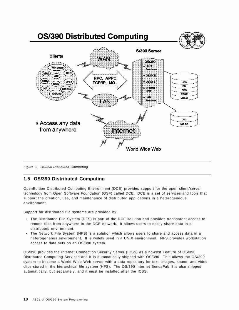
Figure 5. OS/390 Distibuted Computing
1.5 OS/390 Distributed Computing
OpenEdition Distributed Computing Environment (DCE) provides support for the open client/servertechnology from Open Software Foundation (OSF) called DCE. DCE is a set of services and tools thatsupport the creation, use, and maintenance of distributed applications in a heterogeneousenvironment.
Support for distributed file systems are provided by:
• The Distributed File System (DFS) is part of the DCE solution and provides transparent access toremote files from anywhere in the DCE network. It allows users to easily share data in adistributed environment.
• The Network File System (NFS) is a solution which allows users to share and access data in aheterogeneous environment. It is widely used in a UNIX environment. NFS provides workstationaccess to data sets on an OS/390 system.
OS/390 provides the Internet Connection Security Server (ICSS) as a no-cost Feature of OS/390Distributed Computing Services and it is automatically shipped with OS/390. This allows the OS/390system to become a World Wide Web server with a data repository for text, images, sound, and videoclips stored in the hierarchical file system (HFS). The OS/390 Internet BonusPak II is also shippedautomatically, but separately, and it must be installed after the ICSS.
10 ABCs of OS/390 System Programming

The OS/390 system includes OpenEdition DCE which is a solution for distributed computing. DCE issupported by the Open Software Foundation (OSF), which looked at multiple open distributed solutionsfrom multiple vendors and selected the best functions to be integrated into one solution called DCE.
The OpenEdition DCE for OS/390 consists of:
• OpenEdition DCE Base Services (base element in OS/390)• OpenEdition DCE Security Server (optional feature)• OpenEdition DCE Distributed File Server (base element)• OpenEdition DCE Application Support (optional feature)
Distributed applications use a client/server model based on Remote Procedure Call (RPC) to provideconnectivity from client application through the network to the server application. A quick overview ofthe DCE client/server model: A client application uses RPC to call a service (function) from a server,RPC uses the services of the DCE Distributed Directory to locate the server, Distributed Security isinvoked to authenticate both the client and the server, Distributed Time Services will synchronize theclient and server processing, and threads allows parallelism in execution.
DFS is a distributed client/server application which uses the DCE services. DFS provides access to theOpenEdition HFS or to local DFS file systems. Some of the advantages of DFS over similar distributedfile system solutions is that DFS provides caching of data which reduces network load and improvesperformance. Data can be replicated (shadow copies) across multiple servers, resulting in improvedreliability and availability.
NFS is a solution well known in the UNIX environment. The DFSMS/MVS NFS feature now providesboth server and client support. This enables one OS/390 system to exchange data files with anotherusing NFS client/server technology. Each OS/390 system with the DFSMS/MVS 1.3 NFS feature canread from or write to any other OS/390 system which has the DFSMS/MVS NFS feature installed.DFSMS/MVS NFS enables OS/390 UNIX applications on one OS/390 system to read or write MVSconventional data sets and/or OS/390 UNIX Hierarchical File System (HFS) files on another OS/390system.
DFS and NFS provide file server capabilities for OS/390 in a distributed heterogeneous environment.The LAN services previously introduced are limited to LANs, while NFS and DFS are available for useon both LANs and WANs (TCP/IP, VTAM AnyNet).
The Internet Connection Security Server (ICSS) for MVS is based on OS/390 UNIX services. TheInternet Connection Security Server is delivered as a no-cost feature with OS/390.
The OS/390 Internet Bonus Pak II is a set of sample HTML pages, programs, and redbooks thatdemonstrate how to:
• Retrieve data from DB2, IMS, and CICS databases and present this data to a client browser• Write simple Hypertext Markup Language (HTML) pages• Write simple Common Gateway Interface (CGI) programs• Write simple Java programs• Write simple DB2 WWW macros• Use secure sockets• Use Server Side Includes
Physically, the sample HTML pages and executables reside in directories in the OS/390 UNIX MVSHierarchical File System (HFS).
Chapter 1. Network Management 11

Figure 6. eNetwork
1.6 Networking Products
Until OS/390 V2R5, IBM marketed two separate networking products:
• Virtual Telecommunications Method (VTAM)
• Transmission Control Protocol / Internet Protocol (TCP/IP)
VTAM has been around for some time and forms the backbone of IBM ′s Systems Network Architecture(SNA) networking protocol including basic connectivity such as 3270, SDLC and NJE.
TCP/IP is a relative newcomer and is the basis for OS/390′s presence on the WWW. It enables FTPand Telnet (both client and server), as well as webserving, LPR, and LPD, to name a few.
As of OS/390 Version 2 Release 6, both products were merged under the banner of eNetworkCommunications Server. However, they still remain functionally separate components as eNetworkCommunications Server SNA and eNetwork Communications Server IP.
1.6.1 VTAM
VTAM provides a method by which application programs can communicate with telecommunicationdevices and their users. VTAM was the first IBM program to allow programmers to deal with devicesas “logical units” without having to understand the details of line protocols and device operation. Priorto VTAM, programmers used IBM′s Basic Telecommunications Access Method (BTAM) to communicatewith devices that used the binary synchronous (BSC) and start-stop line protocols.
12 ABCs of OS/390 System Programming

1.6.2 SNASystems Network Architecture (SNA) is IBM′s proprietary network architecture and set of implementingproducts for network computing within an enterprise. It existed prior to and became part of IBM′sSystems Application Architecture (SAA) and it is currently part of IBM′s Open Blueprint. With theadvent of multi-enterprise network computing, the Internet, and the industry standard open networkarchitecture of TCP/IP, IBM is blurring the edges between VTAM/SNA and TCP/IP application supportvia the enterprise-wide product eNetwork Communications Server.
SNA itself contains several functional layers and includes a communications protocol for the exchangeof control information and data, and a data link layer, Synchronous Data Link Control (SDLC). SNAincludes the concepts of nodes that can contain both physical units that provide certain setup functionsand logical units, each associated with a particular network transaction.
1.6.2.1 SDLCSynchronous Data Link Control (SDLC) is a transmission protocol developed by IBM in the 1970s as areplacement for its binary synchronous (BSC) protocol.
SDLC became part of IBM′s Systems Network Architecture (SNA) and the more comprehensiveSystems Application Architecture (SAA) and its more recent Open Blueprint. SDLC is still commonlyencountered and probably the prevalent data link protocol in today′s mainframe environment.
It utilizes the concept of a Primary and a Secondary partner in any communications link, referred to asthe Primary Logical Unit (PLU) and the Secondary Logical Unit (SLU). Typically in IBM mainframenetworks, the host mainframe is the PLU and workstations, for example a 3270 device, and otherdevices are SLUs. Each SLU has its own address in the network, thus enabling it to be identifiedindividually. Typically, multiple devices or SLUs are attached to a common line in what is known as amultipoint or multidrop configuration. SDLC is primarily intended for remote communication oncorporate wide-area networks (WANs).
1.6.2.2 APPNAdvanced Peer to Peer Networking (APPN) protocol was developed by IBM to supportcomputer-to-computer (not necessarily 3270) communications, often referred to as LU6.2. It is anon-hierarchical protocol, that is, either end can initiate a session based around the concept of:
• End Nodes - The application programs, either clients or servers• Network Nodes - Used to route information around the network between end nodes.
1.6.2.3 32703270 is the session protocol used to establish a screen connection to a System/390 mainframe.
It started life as the traditional 24x80 green screen and developed into the more usable, but stillessentially dumb screens or terminal emulators we use today:
• The 3270 model 2 24x80• The 3270 model 3 32x80• The 3270 model 4 43x80• The 3270 model 5 27x132• Extended Attribute Support (colors, blink, etc.)
Chapter 1. Network Management 13

Figure 7. SNA Layered Architecture
1.7 SNA Layered Architecture
This section provides an overview of SNA, including its architectural objectives, network components,data transport services, transaction services, and network management services.
A data communication network is a collection of hardware and software components that enable endusers to exchange data. To send or receive data through a network, end users interact withcommunication devices such as telephones, terminals, or computers. The term end user is used toidentify both (1) individuals who interact with the network through a workstation and (2) applicationprograms. The architecture views end users as the ultimate sources and destinations of informationthat flows through a network.
Data communication requires that network components agree on both the layouts of the messagesthey exchange and the actions they take based on the kinds of data they receive. The layouts arereferred to as formats, and the actions taken are referred to as protocols. Formats and protocolstogether constitute an architecture.
Systems Network Architecture (SNA) is a data communication architecture established by IBM tospecify common conventions for communication among the wide array of IBM hardware and softwaredata communication products. The manner in which products internally implement these commonconventions can differ from one product to another. But because the external interface of eachimplementation is compatible, different products can communicate without the need to distinguishamong the many possible product implementations.
14 ABCs of OS/390 System Programming

SNA functions are divided into a hierarchical structure that consists of seven well-defined layers. Eachlayer in the architecture performs a specific set of functions. In the graphic you can see the SNA ′sseven layers and their major functions.
SNA defines formats and protocols between layers that permit equivalent layers (layers at the samelevel within the hierarchy) to communicate with one another. Each layer performs services for the nexthigher layer, requests services from the next lower layer, and communicates with equivalent layers.To illustrate this concept, consider end-user data that requires encryption. The two transmissioncontrol layers encipher and decipher data independently of the functions of any other layer. Thetransmission control layer in the originating node enciphers the data it receives from the data flowcontrol layer. It then requests that the path control layer route the enciphered data to the destinationnode. The transmission control layer in the destination node deciphers the data that the path controllayer delivered. It then requests that the data flow control layer give the deciphered data to thedestination end user.
Chapter 1. Network Management 15

Figure 8. Hardware and software components
1.8 Hardware and software components
Hardware and software components implement the functions of the seven architectural layers.Hardware components include:
• Processors such as the ES/9000(*) family
• Distributed processors such as the Application System/400(*)
• Communication controllers such as the 372X and 374X series
• Cluster controllers
• Workstations
• Printers
The software components that implement SNA functions include:
• Operating systems such as Multiple Virtual Storage/Enterprise Systems Architecture (MVS/ESA(*)),and Operating System/400(*) (OS/400(*))
• Telecommunication access methods such as the Virtual Telecommunications Access Method(VTAM(*)) and Communications Manager/2 (CM/2(*))
• Application subsystems such as Customer Information Control System (CICS)
• Network control programs such as the Advanced Communication Function for Network ControlProgram (NCP)
16 ABCs of OS/390 System Programming

The graphic illustrates one possible network configuration of these hardware and softwarecomponents.
Chapter 1. Network Management 17

Figure 9. The network blueprint
1.9 The Network Blueprint
IBM ′s networking design strategy employs a “Networking Blueprint” that provides an open, highlymodular framework for structuring networks using industry-wide standards. The blueprint is designedto facilitate the creation of an evolutionary and flexible plan that an organization can specifically tailorto meet its needs; this is much needed considering today ′s fast-moving technologies and the diversityof networks. The graphic shows the modules used to describe the Networking Blueprint.
The Networking Blueprint supports the implementation of multiple protocols, as well as integratingthese protocols into a cohesive, modular structure. The Networking Blueprint defines layers offunctions, plus a systems management backplane. SNA Advanced Peer-to-Peer Networking(*) SNAAdvanced Peer-to-Peer Networking (APPN), is part of the transport layer, and it is one of the protocolsthat can be used in this layer.
APPN′s any-to-any connectivity makes it possible for large and small networks alike to communicateover local- and wide-area networks, across slow and fast links.
APPN provides two basic functions: keeping track of the location of resources in the network, andselecting the best path to route data between resources. APPN nodes dynamically exchangeinformation about each other; therefore, customers may never have to deal with complicated systemand path definitions. APPN nodes limit the information they exchange, enabling more efficient use ofnetwork resources.
18 ABCs of OS/390 System Programming

High-performance routing (HPR) is a small but powerful evolutionary extension to APPN. It enhancesdata routing performance via decreasing intermediate node processing. HPR also increases sessionreliability via “nondisruptive path switch.” The two main components of HPR are rapid-transportprotocol (RTP) and automatic network routing (ANR).
Systems Network Architecture was designed with certain objectives in mind. These objectives addresscommon concerns of data communication network users. One such concern is the reliability of thenetwork. Recoverable data communication errors must be handled transparently to the user. At thedata link layer of the architecture, error-checking protocols ensure that error detection and messageretries are performed automatically. When errors are not recoverable, communicating partners mustbe able to achieve a mutual understanding as to the results of attempted message transfers. Protocolsat the presentation services layer provide positive-negative responses and establish synchronizationpoints, which enable communicating partners to ensure the consistency of their resources.
For some applications, consistent, fast performance is needed to handle updates immediately; for otherapplications, it is important to send data as inexpensively as possible. APPN includes several featuresthat can handle this type of traffic mix efficiently. APPN′s priority services ensure that important datamoves through the network quickly. Similarly, by using intelligent class-of-service routing, APPN nodesconsider factors such as security, cost, delay, and throughput to select the best route for different typesof data. Unlike other protocols that react to network bottlenecks by dropping and resending packets,APPN avoids network congestion by using adaptive pacing, which ensures a higher, more consistenttraffic volume.
High-performance routing (HPR) improves on APPN ′s reliability by providing greater session reliabilityin case of link and node failure via nondisruptive path switch. It is accomplished transparently to boththe sessions and end users.
An SNA network is dependable because SNA products recognize and recover from loss of data duringtransmission, use flow control procedures to prevent data overrun and avoid network congestion,identify failures quickly, and recover from many errors with minimal involvement of network users.SNA products also increase network availability through options such as the extended recovery facility,backup host, alternate routing capability, and maintenance and recovery procedures integrated intoworkstations, modems, and controllers.
Another concern is the efficiency with which data is transferred. Components within SNA act topromote efficiency both by selecting options that maximize data transmission throughput and by takingaction to reduce network congestion when it is detected. Route selection services, for example, canselect optimal routes for data transmission.
When too much data is introduced into the network, congestion can occur. Severe congestion blocksthe flow of messages and can result in the loss of data. Protocols at the transmission control and pathcontrol layers prevent overload and deadlocks by controlling the pace at which messages flow throughthe network.
APPN features help eliminate unnecessary network control traffic, thus providing more bandwidth formoving data through the network. APPN nodes never broadcast changes to all machines in thenetwork. Instead, only network nodes exchange topology information, and they exchange thisinformation only when changes occur in the backbone of the network. Other protocols broadcastrouting information at frequent regular intervals, even if nothing changes in the network. Other APPNfeatures, like directory caching and central directory servers, limit searches for other resources in thenetwork, and, as a result, improve network performance. In summary, APPN permits more bandwidthfor real work for applications, without the need to invest in new equipment.
An ongoing objective of SNA is ease of use, both for end users and network personnel. Because SNAproducts have compatible interfaces, they can connect and communicate with one another.Application program interfaces at the presentation services layer, for example, shield end users from
Chapter 1. Network Management 19

concern with the underlying details of communication protocols. When hardware and softwareupgrades are required, the functional independence of the SNA layers enables any one layer to beenhanced or modified without disrupting the functions of any other layer. To link independentnetworks, network interconnection protocols are provided that enable the networks to communicatewithout redefining network identifiers. An example of this is Common Programming Interface forCommunications (CPI-C), which can protect an organization′s investment in application programming.The services provided by APPN include network topology updates and automatic route selection, whichmake it unnecessary to predefine node locations and routes between nodes. Thus, network operatorscan add new components to the network without affecting the network availability for existing users.
With peer-to-peer communication protocols, end users benefit through more timely access to theirapplications because they are less dependent on the system programming staff to code networkdefinitions. As workstations and applications first become available in the network, or are moved,APPN directory functions locate them dynamically without requiring coordinated definitions to be codedby the system programmer. This improves network availability and end-user productivity.
Resource sharing addresses the concern for fair and effective resource utilization. The sharing ofaccess to storage devices, output devices, and data communication lines is paramount for containingnetwork costs. Resource sharing is addressed at many levels within SNA, from the multiplexing ofdata links to the sharing of sessions by individual end-user transactions.
At the same time other mechanisms control the equitability with which services are provided tonetwork users. Transmission priorities and classes of service enable equal service to be given tosessions of equal priority, or preference given to sessions of higher priority.
The security of data is an increasing need for today ′s networks, which have become the vehicles forsuch sensitive data as banking transactions. Protocols for data encryption at the transmission controllayer, and password verification at the transaction services layer and the presentation services layer,serve the data security objective.
Tools for resource management provide the ability to identify errors, help in problem determination,and maintain accounting data on network resource usage. Capabilities exist within all layers of SNAfor monitoring and reporting errors relating to the functions for which they are responsible. Usagestatistics facilitate fair charging of network users, performance tuning, capacity planning, and capitalbudgeting.
IBM offers communication products that conform to SNA specifications. Because of IBM′s ongoingdevelopment of products compatible with this architecture, organizations often can substitute one typeof SNA product for another as their needs change. In an SNA network, newer devices with improvedcapabilities can coexist with older ones. As an organization′s SNA network evolves with the additionof new workstations, processors, communication facilities, and applications, it can continue using theapplications already in place.
• Subarea Networks
Networks that use peer-to-peer communication protocols can be integrated with subarea networks,allowing application sessions between peer-to-peer nodes and hierarchical nodes.
• Dependent LU Support
Users of APPN can carry their investment in dependent LUs into the future of dynamic AdvancedPeer-To-Peer (APPN) networking. Dependent LUs can continue to access VTAM applications in thesame VTAM domain, or in different domains, using subarea protocols. In addition, dependent LUsin one domain can access VTAM applications in a different domain utilizing APPN protocolsbetween domains. This allows the user to begin implementing APPN instead of subarea protocolsbetween VTAM domains, while continuing to provide access to VTAM applications from dependentLUs in different domains.
20 ABCs of OS/390 System Programming

• Applications
Existing applications continue to be supported for dependent LUs and independent LUs. There isno change to APIs.
• Ease of Migration
Migrating to a client/server environment does not have e to be complex,time-consuming, and expensive. Advanced Peer-to-Peer Networking (APPN) provides a bettersolution for migrating both networks and applications. With APPN, a network can be migrated tothe client/server environment at any pace. The new version of VTAM, for example, allowstraditional SNA networks to be integrated with APPN networks. APPN also enables running bothexisting mainframe applications and new client/server applications at the same time.
SNA helps find and resolve problems that can occur in a network. SNA management servicesfunctions in each network component to assist in problem determination. Also, the NetView(*) family ofproducts, which is network management software that runs on a host processor, has components thatmonitor, collect, and store network data. Other system management functions built into the NetViewprogram allow rapid problem determination, increase network availability, and minimize the number ofthe personnel needed to operate and maintain the SNA network.
An SNA network accommodates such facilities and technologies as:
• Digital networks
• Digitized voice
• Distributed systems
• Fiber optics
• Graphics
• Public packet-switching data networks
• Satellites
• Token-ring networks
• Videotex
• Client/server
• Ethernet
• Frame relay
• Security.
The SNA Network Interconnection (SNI) facility helps exchange information with another independentorganization or merge separately-administered subarea networks into one.
The SNA Network Interconnection facility allows users in one SNA network to access information andapplication programs in other SNA networks. Each interconnected network can maintain its existingmanagement procedures and controls. A “gateway” between two or more SNA networks connectsthem operationally while isolating their administrative characteristics from one another. Network usersare not aware of network boundaries.
Two APPN subnets may communicate with each other via a border node. The border node allowssessions between users in different APPN subnets while isolating the subnets′ topology informationfrom one another.
Chapter 1. Network Management 21

Figure 10. A subarea network
1.10 A subarea network
A data communication network can be described as a configuration of nodes and links. Nodes are thenetwork components that send data over, and receive data from, the network. Node implementationsinclude processors, controllers, and workstations. Links are the network components that connectadjacent nodes. Nodes and links work together in transferring data through a network.
A node is a set of hardware and associated software components that implement the functions of theseven architectural layers. Although all seven layers are implemented within a given node, nodes candiffer based on their architectural components and the sets of functional capabilities they implement.Nodes with different architectural components represent different node types. Four types of nodesexist: type 5 (T5), type 4 (T4), type 2.0 (T2.0), and type 2.1 (T2.1).
Nodes that perform different network functions are said to act in different network roles. It is possiblefor a given node type to act in multiple network roles. A T4 node, for example, can perform aninterconnection role between nodes at different levels of the subarea network hierarchy, or betweennodes in different subarea networks. The functions performed in these two roles are referred to asboundary function and gateway function, respectively. T2.1 and T5 nodes can also act in severaldifferent network roles. Node roles fall into two broad categories: hierarchical roles and peer-orientedroles.
Hierarchical roles are those in which certain nodes have a controlling or mediating function withrespect to the actions of other nodes. Hierarchical networks are characterized by nodes of all fourtypes acting in hierarchical roles. Within such networks, nodes are categorized as either subarea
22 ABCs of OS/390 System Programming
nodes (SNs) or peripheral nodes (PNs). Subarea nodes provide services for and control overperipheral nodes. Networks consisting of subarea and peripheral nodes are referred to as subareanetworks.
• Subarea nodes
Type 5 (T5) and type 4 (T4) nodes can act as subarea nodes. T5 subarea nodes provide the SNAfunctions that control network resources, support transaction programs, support network operators,and provide end-user services. Because these functions are provided by host processors, T5nodes are also referred to as host nodes.
T4 subarea nodes provide the SNA functions that route and control the flow of data in a subareanetwork. Because these functions are provided by communication controllers, T4 nodes are alsoreferred to as communication controller nodes.
• Peripheral nodes
Type 2.0 (T2.0) and type 2.1 (T2.1) nodes can act as peripheral nodes attached to either T4 or T5subarea nodes. Peripheral nodes are typically devices such as distributed processors, clustercontrollers, or workstations. A T2.1 node differs from a T2.0 node by the T2.1 node′s ability tosupport peer-oriented protocols as well as the hierarchical protocols of a simple T2.0 node. A T2.0node requires the mediation of a T5 node in order to communicate with any other node. Subareanodes to which peripheral nodes are attached perform a boundary function and act as subareaboundary nodes.
Chapter 1. Network Management 23

Figure 11. An APPN network
1.11 An APPN network
APPN extensions allow greater distribution of network control by enhancing the dynamic capabilities ofthe node. Nodes with these extensions are referred to as APPN nodes, and a network of APPN nodesmakes up an APPN network. A low-entry networking (LEN) node can also attach to an APPN network.An APPN node can dynamically find the location of a partner node, place the location information indirectories, compute potential routes to the partner, and select the best route from among thosecomputed. These dynamic capabilities relieve network personnel from having to predefine thoselocations, directory entries, and routes. APPN nodes can include processors of varying sizes such asthe Application System/400 (AS/400), the Enterprise System/9370(*) (ES/9370(*)) running underDistributed Processing Program Executive/370 (DPPX/370), the Personal System/2(*) (PS/2(*)) runningunder Operating System/2(*) (OS/2(*)), and VTAM running under Multiple Virtual Storage/EnterpriseSystems Architecture (MVS/ESA).
Peer-oriented protocols enable nodes to communicate without requiring mediation by a T5 node, givingthem increased connection flexibility. APPN defines two possible roles for a node in an APPN network,that of an end node and that of a network node. (Network nodes provide additional options that canfurther distinguish them.)
T2.1 nodes can act as either APPN or LEN nodes. T5 nodes can also act as APPN or LEN nodes, buthave additional capability to interconnect subarea and APPN networks by interchanging protocolsbetween them. (In this capacity, they are called interchange nodes). Together with its subordinate T4nodes, a T5 node can also form a composite LEN node or a composite network node. As composite
24 ABCs of OS/390 System Programming

nodes, they appear as single LEN or network nodes to other LEN or APPN nodes to which they areinterconnected.
If two network nodes do not support the border node option and are located in two separate net-IDsubnetworks, CP-CP sessions cannot be established between them. For the two network nodes tocommunicate, a LEN connection may be established between the two. This allows the two net-IDsubnetworks to communicate, but does not support any APPN function. If NN1 in subnet A is toestablish a session with NN2 in subnet B, all LUs in subnet A must be predefined to NN2 in subnet B.The network nodes in both subnets are APPN nodes, but since they communicate across net-IDsubnetwork boundaries, they are defined to each other via LEN links.
• End nodes
These are located on the periphery of an APPN network. An end node obtains full access to theAPPN network through one of the network nodes to which it is directly attached--its network nodeserver. The two kinds of end nodes are APPN end nodes and LEN end nodes. An APPN end nodesupports APPN protocols through explicit interactions with a network node server. Such protocolssupport dynamic searching for resources and provide resource information for the calculation ofroutes by network nodes. A LEN end node is a LEN node attached to a network node. AlthoughLEN nodes lack the APPN extensions, they are able to be supported in APPN networks using theservices provided them by network nodes. In an APPN network, when a LEN node is connected toanother LEN node, or to an APPN end node, it is referred to simply as a LEN node. Whenconnected to an APPN network node, however, it is referred to as a LEN end node.
• Network nodes
Together with the links interconnecting them, network nodes form the intermediate routing networkof an APPN network. Network nodes connect end nodes to the network and provide resourcelocation and route selection services for them. Routes used to interconnect network users areselected based on network topology information that can change dynamically. The graphicrepresents one possible APPN network configuration and contains LEN end nodes as well as APPNnodes.
• Network node server
This is a network node that provides resource location and route selection services to the LUs itserves. These LUs can be in the network node, itself, or in the client end nodes. A network nodeserver uses CP-CP sessions to provide network information for session setup in order to supportthe LUs on served APPN end nodes. In addition, LEN end nodes can also take advantage of theservices of the network node server. A LEN end node, unlike an APPN end node, must bepredefined by the network operator as a client end node for which the network node acts asserver. Any network node can be a network node server for end nodes that are attached to it. Theserved end nodes are defined as being in that network node server′s domain.
• Central directory server
This is a network node that builds and maintains a directory of resources from the network. Thepurpose of a CDS is to reduce the number of network broadcast searches to a maximum of oneper resource. Network nodes and APPN end nodes can register their resources with a CDS, whichacts as a focal point for resource location information.
A CDS can be involved in APPN end node resource registration. An APPN end node registers itsits resources to improve network search performance. When an APPN end node registers itsresources with its network node server, it can request that its network node server also registerthem with a CDS. Entries in a directory database can be registered, defined, or dynamic.
When a network node receives a search request for a resource that has no location information,the network node first sends a directed search request to a CDS if there is one. The CDS searchesin its directory for information about the location of the resource. If it does not find the location ofthe resource, the CDS searches end nodes in its domain, other CDSs, and, if necessary, the entirenetwork (via a “broadcast search”). If the resource is still not found, the CDS notifies the network
Chapter 1. Network Management 25

node that originally requested the search that the search is unsuccessful. A central directory clientis a network node that forwards directory searches to a CDS.
26 ABCs of OS/390 System Programming

Figure 12. Subareas
1.11.1 Subareas
SNA defines the following network configurations:
• A hierarchical network consisting of subarea nodes and peripheral nodes
• A peer-oriented network consisting of APPN and LEN nodes
• A mixed network that combines one or more hierarchical subnets with one or more peer-orientedsubnets.
The organization of a hierarchical network structure is determined by the way control of networkservices is maintained. Host nodes containing SSCPs are responsible for overall control ofcommunication in the hierarchical network.
A hierarchical network might include LEN or APPN nodes that are attached as peripheral nodes.These nodes can communicate with each other through a subarea network if the boundary nodes towhich they are attached support the basic SSCP-independent LU-LU protocols needed for such peerinteractions.
A subarea consists of one subarea node and the peripheral nodes that are attached to that subareanode. The concept of a subarea applies only to subarea networks and composite networks. Thenetwork configuration in the visual contains five subarea nodes and seven peripheral nodes. Becauseeach subarea node and its attached peripheral nodes constitute a subarea,
Chapter 1. Network Management 27

Figure 13. Domains in a subarea network
1.11.2 Domains in a subarea network
A domain is an area of control. The concept of a domain within a subarea network differs from thatwithin an APPN network. Within a subarea network, a domain is that portion of the network managedby the control point in a T5 subarea node. The control point in a T5 subarea node is called a systemservices control point (SSCP).
When a subarea network has only one T5 node, that node must manage all of the network resources.A subarea network that contains only one T5 node is a single-domain subarea network. When thereare multiple T5 nodes in the network, each T5 node may control a portion of the network resources. Asubarea network that contains more than one T5 node is a multiple-domain subarea network. In amultiple-domain subarea network, the control of some resources can be shared between SSCPs.Some resources can be shared serially and some concurrently. For more information on resourcesharing in subarea networks, see “Defining Shared Control of Resources in Subarea Networks” inChapter 4, “Defining Network Resources.” The visual illustrates two domains, A and B, joined bydirect-attached T4 nodes to form a multiple-domain subarea network.
28 ABCs of OS/390 System Programming

Figure 14. Network node domains in APPN
1.11.3 Network node domains in APPN
An APPN network constitutes a peer-oriented SNA network. All APPN nodes are considered to bepeers and do not rely on other nodes to control communication in the network the way a subarea nodecontrols communication between peripheral nodes. There is, however, a measure of hierarchicalcontrol because a network node server provides certain network services to its attached end nodes.The difference is that, in APPN networks, hierarchical control is not determined by product orprocessor type as it is in subarea networks, where only large host processors contain SSCPs and nodetypes generally reflect product types.
The domain of a node in an APPN network is that portion of the network served by the control point inthe node. The control point in an APPN node is called simply a control point (CP). An end nodecontrol point′s domain consists solely of its local resources. It is included within the domain of itsnetwork node server. A network node control point′s domain includes the resources in the networknode and in any client end nodes (nodes for which the network node is acting as the network nodeserver) attached directly to the network node.
APPN networks are by definition multiple-domain networks. The graphic illustrates an APPN networkcontaining four network node domains, A, B, C, and D. The domains of the end nodes are includedwithin the domains of their respective network node servers.
Chapter 1. Network Management 29
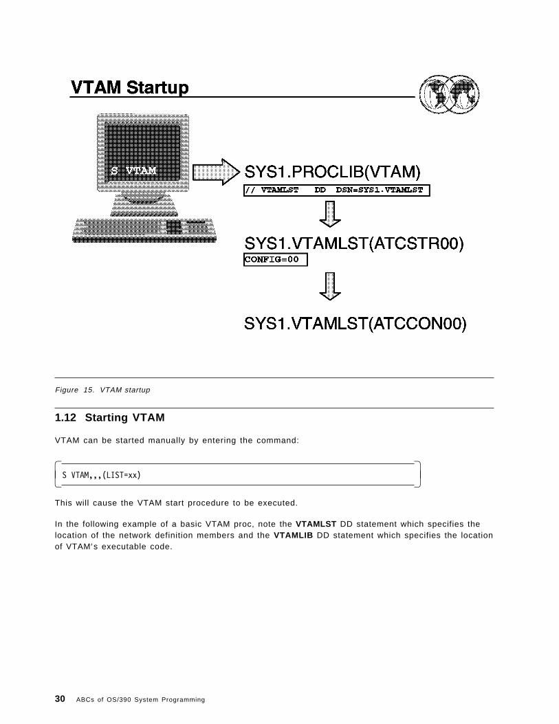
Figure 15. VTAM startup
1.12 Starting VTAM
VTAM can be started manually by entering the command:
� �S VTAM,,,(LIST=xx)� �
This will cause the VTAM start procedure to be executed.
In the following example of a basic VTAM proc, note the VTAMLST DD statement which specifies thelocation of the network definition members and the VTAMLIB DD statement which specifies the locationof VTAM′s executable code.
30 ABCs of OS/390 System Programming

Figure 16. VTAM procedure
1.12.1 VTAM procedure
The first thing VTAM looks for is an ATCSTRxx member in its VTAMLST data set, where xx is theLIST=xx value and can be any 2-character alphanumeric value.
The ATCSTRxx member contains VTAM start parameters that define VTAM′s identity on the network aswell as tuning options and a pointer to the major node startup list, ATCCONxx.
If no LIST= parameter was specified on the S VTAM command, the default value of 00 is used.
For example:
The command S VTAM,,,(LIST=Z9) will cause VTAM to read startup parameters from ATCSTRZ9
The command S VTAM,,,(LIST=EX) will cause VTAM to read startup parameters from ATCSTREX
The command S VTAM,,,(LIST=99) will cause VTAM to read startup parameters from ATCSTR99
The command S VTAM will cause VTAM to read startup parameters from the default ATCSTR00
A typical ATCSTRxx member might contain:
Chapter 1. Network Management 31

� �SSCPID=0061,CONFIG=00,HOSTSA=130,NETID=GBIBMPGX,SSCPNAME=PGXYA,IOBUF=(100,256,19,,12,30)
� �
For a complete description of the parameters and their values refer to OS/390 eNetworkCommunications Server: SNA Resource Definition Reference, SC31-8565.
Following is a brief description:
SSCPID A decimal integer in the range of 0-65535 that uniquely identifies this VTAM to any otherconnected VTAMs that will communicate with it. It is used in the setup of cross-domainsessions.
SSCPNAME This is a 1 to 8-character name that uniquely identifies this VTAM to any other connectedVTAMs that will communicate with it. It is also used in the setup of cross-domainsessions.
HOSTSA This defines this VTAM′s subarea number.
NETID This specifies the name of the network containing this VTAM.
CONFIG This is a 2-character suffix of the ATCCONxx member that contains the list of major nodesto be automatically activated at startup.
IOBUF This is one of the many VTAM tuning parameters. The values inside the bracketsdetermine how VTAM allocates and manages storage associated with a particular bufferpool.
1.12.1.1 ATCCONxx
The ATCCONxx member, where xx is the value specified on the CONFIG=.. parameter on ATCSTRxx,contains a list of the members or major nodes that VTAM will automatically activate on startup.
Typically, these will include at least:
• The TSO application major node
• One or more CICS application major nodes
• A local 3270 terminal′s major node
Examples of other major nodes, depending on the hardware and software installed, can include:
• An NCP major node
• An XCA major node
• An adjacent SSCP table major node
• A PATH table major node
• A Cross-Domain Resource Manager major node
• A Cross-Domain Resources major node
• A channel-to-channel Adapter major node
• Additional application major nodes, for example, NetView
32 ABCs of OS/390 System Programming

The above list is not intended to be exhaustive, merely to give examples of the major nodes that mightbe included in a typical production startup list.
Major nodes are discussed further in 1.12.4, “VTAM major nodes” on page 38.
For reference, see OS/390 eNetwork Communications Server SNA Resource Definition Reference,SC31-8565 and OS/390 eNetwork Communications Server SNA Resource Definition Samples, SC31-8566.
Chapter 1. Network Management 33

Figure 17. VTAM data sets
1.12.2 VTAM data sets
VTAM configuration depends on the customization of various control or parameter files. AdvancedVTAM customization can involve writing complex user exits and changes to such items as theUnformatted System Services (USS) table, the LOGMODE table, and the Class Of Service (COS) table,to name just a few. These members are located in the VTAMLIB data set, usually SYS1.VTAMLIB.
To start with, however, basic VTAM configuration can be achieved by tailoring the following:
• The VTAM start procedure SYS1.PROCLIB(VTAM).
• The VTAM startup member SYS1.VTAMLST(ATCSTRxx).
• The VTAM major node activation list SYS1.VTAMLST(ATCCONxx).
• Major node members, usually located in SYS1.VTAMLST. These members are used to define theSNA network, and are discussed in 1.12.4, “VTAM major nodes” on page 38.
34 ABCs of OS/390 System Programming

Figure 18. VTAM commands
1.12.3 VTAM commands
VTAM operator commands fall into four categories:
1. The Display commandsD NET,...
2. The VARY commandsV NET,...
3. The Modify commandsF NET,...
4. The Halt commandsZ NET,...
The following command descriptions and examples give an overview of the VTAM Operator commandsavailable. For a complete list of VTAM Operator commands and their syntax and use refer to OS/390eNetwork Communications Server: SNA Operation, SC31-8567.
Chapter 1. Network Management 35

1.12.3.1 Display commands
The basic VTAM Display commands can be used to interrogate VTAM for information about the statusof communications links, devices, applications, and even the state of VTAM itself.
The experienced VTAM operator or systems programmer can often successfully diagnose many VTAMrelated problems simply by analyzing the output of the various Display commands.
Some of the more useful include:
Table 1. VTAM Display commands
Command Description
D NET,VTAMOPTS Display VTAM options, including SUBAREA Number, NETID, SSCPNAME,SSCPID
D NET,BFRUSE Display information about VTAM ′s virtual storage and buffer pool usage
D NET,APPLS Display the applications (APPLIDS) that VTAM knows about
D NET,PATHTAB Display the status of communications PATHs between subareas in the VTAMnetwork
D NET,MAJNODES Display details about major nodes
D NET,ID=..... Display information about the specified VTAM resource
D NET,ID=.....,E Display more information about the specified VTAM resource
1.12.3.2 Vary commands
These commands can be used to deactivate a resource, thereby making it unavailable on the network,or to reactivate a failed resource, for example.
Table 2. VTAM Vary commands
Command Description
V NET,ACT,ID=..... Activate the specified resource
V NET,INACT,ID=..... Deactivate the specified resource
V NET,INACT,ID=.....,I Immediately deactivate the specified resource
V NET,INACT,ID=.....,F Force-deactivate the specified resource
V NET,ACQ,ID=..... Acquire the specified resource (NCP or non-switched PU) without activating it- used during network recovery whereby this VTAM can take ownership ofanother VTAM ′s resource
1.12.3.3 Modify commands
The VTAM Modify commands are used for the more advanced VTAM functions such as replacing anactive LOGMODE table, for example, without having to restart VTAM, or to start and stop VTAMtracing.
Table 3. VTAM Modify commands
Command Description
F NET,TNSTAT,CNSL=YES Activate the VTAM tuning statistics display and output to the console
F NET,NOTNSTAT Deactivate the VTAM tuning statistics display
F NET,TRACE,............ Initiate or Modify VTAM tracing
F NET,NOTRACE,............ Terminate VTAM tracing
36 ABCs of OS/390 System Programming

1.12.3.4 Halt commands
The VTAM Halt commands are used to stop VTAM processing.
Table 4. VTAM Halt commands
Command Description
Z NET Terminate VTAM processing normally
Z NET,QUICK Terminate VTAM processing immediately without waiting for normaltermination of existing sessions - should only be used when normaltermination does not complete successfully
Z NET,CANCEL Abends VTAM - should only be used when both Z NET and Z NET,QUICK areunsuccessful
Chapter 1. Network Management 37
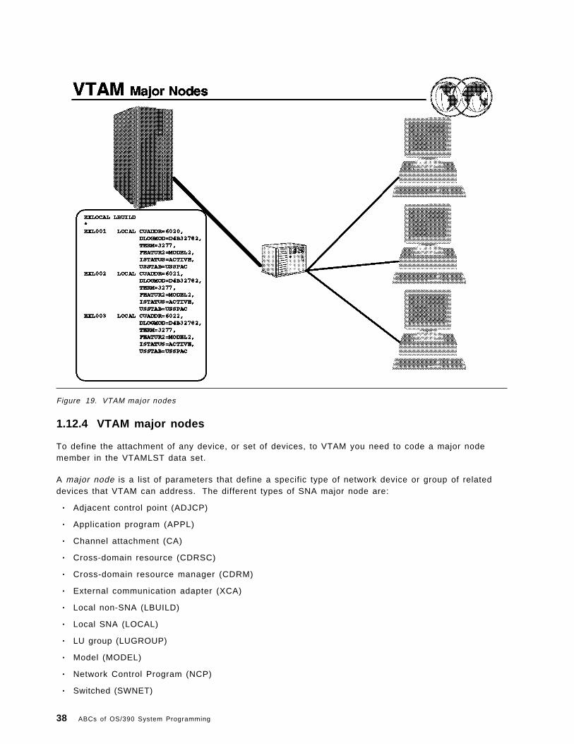
Figure 19. VTAM major nodes
1.12.4 VTAM major nodes
To define the attachment of any device, or set of devices, to VTAM you need to code a major nodemember in the VTAMLST data set.
A major node is a list of parameters that define a specific type of network device or group of relateddevices that VTAM can address. The different types of SNA major node are:
• Adjacent control point (ADJCP)
• Application program (APPL)
• Channel attachment (CA)
• Cross-domain resource (CDRSC)
• Cross-domain resource manager (CDRM)
• External communication adapter (XCA)
• Local non-SNA (LBUILD)
• Local SNA (LOCAL)
• LU group (LUGROUP)
• Model (MODEL)
• Network Control Program (NCP)
• Switched (SWNET)
38 ABCs of OS/390 System Programming

• Transport resource list (TRL)
For a complete description of each of these, including syntax and coding rules, refer to eNetworkCommunications Server: SNA Resource Definition Reference, SC31-8565 and eNetwork CommunicationsServer: SNA Resource Definition Samples, SC31-8566.
1.12.4.1 Local non-SNA major node
See A.1, “Major node definitions” on page 339 for an example of a local non-SNA major node to definecoax-attached 3270 terminals connected to a channel-attached 3174-type controller.
An XCA major node is used to define an External Communication Adapter to VTAM. For an example ofan OSA device attached to a token ring network definition, see A.2, “XCA Major Node” on page 342.
For an example of a switched major node to define switched communication links to VTAM, see A.3,“Switched major node” on page 343.
Chapter 1. Network Management 39

1.13 TCP/IP
TCP/IP is a set of protocols and applications that allow you to perform certain computer functions in asimilar manner independent of the types of computers or networks being used. When you use TCP/IP,you are using a network of computers to communicate with other users, share data with each other,and share the processing resources of the computers connected to the TCP/IP network.
The TCP/IP component of eNetwork Communications Server supports the following functions:
• Log on to a remote host
• Transfer data sets
• Send and receive electronic mail
• Print on remote printers
• Authenticate network users
• Display IBM GDDM/MVS graphics on X Window System workstations
• Run a command on another host
• Monitor the network
• Query name servers
• Manage network resources
In the following topics we will present an overview and a brief discussion of some of the moresignificant concepts or setup steps to help you get going.
For more information, see eNetwork Communications Server: IP User′s Guide, GC31-8514, and OS/390TCP/IP OpenEdition: Configuration Guide, SC31-8304.
40 ABCs of OS/390 System Programming

Figure 20. TCP/IP layers
1.14 TCP/IP layered structure
The four layers that make up the TCP/IP protocol suite are:
1. Network Interface - The lowest layer is the physical layer and is not actually specified by TCP/IP.The user can access any physical transmission approach including both wide area (WAN) and localarea networks (LAN). The common protocols at this level have been X.25 and Ethernet. Thisindependence from the type of underlying physical network is one of the benefits of TCP/IP.
2. Internetwork layer - This layer provides for routing of datagrams (messages) from one device toanother. This could be from one local device to another, or it could be across a wide area networkwith many intervening networks that must be crossed. Every TCP/IP host has a unique internetaddress which is a combination of a network ID that is assigned centrally, and a local host addressthat is locally administrated. This permits the routing of datagrams (messages between, as well aswithin, enterprises since all hosts have a unique address.
3. Transport layer - The TCP implementation of the transport layer provides for reliable transmissionof data. At the lower layers, all transmissions are in individual packets. The TCP level involvesboth error checking, re-transmission and assembly/disassembly of packets into/from logicalmessages. The TCP level is optional, and an alternative protocol, User Datagram Protocol (UDP)may be used. UDP provides no error checking and no assembly/disassembly of packets.
4. Applications - The application layer consists of many different application types that may or maynot be implemented in a particular TCP/IP installation. Certain applications are implemented innearly all TCP/IP installations. These include TELNET (terminal emulation), SMTP (simple mailtransfer protocol - E-mail), and FTP (file transfer protocol).
Chapter 1. Network Management 41

With TCP/IP it is possible to have connectivity between different vendors′ systems, but not have allthe applications that a user may require. Therefore, the user must compare each vendor′simplementation and set of functions supported in order to insure that all the requirements are met.
42 ABCs of OS/390 System Programming

Figure 21. TCP/IP terminology
1.14.1 TCP/IP terminology
The following are commonly used terms:
Host In the Internet suite of protocols, this is an end system. The end system can beany workstation; it does not have to be a mainframe.
Gateway A functional unit that interconnects two computer networks with different networkarchitectures. A gateway connects networks or systems of differentarchitectures. A bridge interconnects networks or systems with the same orsimilar architectures. In TCP/IP, this is a synonym for router.
Port Each process that wants to communicate with another process identifies itself tothe TCP/IP protocol suite by one or more ports. A port is a 16-bit number, usedby the host-to-host protocol to identify to which higher level protocol orapplication program (process) it must deliver incoming messages. There aretwo types of port:
Well-known Well-known ports belong to standard servers, for exampleTELNET uses port 23. Well-known port numbers range between 1to 1023 (prior to 1992, the range between 256 to 1023 was used forUNIX-specific servers). Well-known port numbers are typicallyodd, because early systems using the port concept required anodd/even pair of ports for duplex operations. Most serversrequire only a single port. The well-known ports are controlledand assigned by the Internet central authority (IANA) and on most
Chapter 1. Network Management 43

systems can only be used by system processes or by programsexecuted by privileged users. The reason for well-known ports isto allow clients to be able to find servers without configurationinformation.
Ephemeral Clients do not need well-known port numbers because theyinitiate communication with servers and the port number they areusing is contained in the UDP datagrams sent to the server. Eachclient process is allocated a port number for as long as it needsby the host it is running on. Ephemeral port numbers havevalues greater than 1023, normally in the range 1024 to 65535.
Socket An endpoint for communication between processes or application programs. Asynonym for port.
Socket address The address of an application program that uses the socket interface on thenetwork. In Internet format, it consists of the IP address of the socket′s host andthe port number of the socket. The application program is usually not aware ofthe structure of the address.
Socket interface A Berkeley Software Distribution (BSD) application programming interface (API)that allows users to easily write their own programs.
Router A router interconnects networks at the internetwork layer level and routespackets between them. The router must understand the addressing structureassociated with the networking protocols it supports and make decisions onwhether, or how, to forward packets. Routers are able to select the besttransmission paths and optimal packet sizes. The basic routing function isimplemented in the IP layer of the TCP/IP protocol stack, so any host orworkstation running TCP/IP over more than one interface could, in theory andalso with most of today′s TCP/IP implementations, forward IP datagrams.However, dedicated routers provide much more sophisticated routing than theminimum functions implemented by IP.
44 ABCs of OS/390 System Programming

Figure 22. What are sockets, anyway?
1.14.2 Sockets
As originally defined by the BSD UNIX, sockets and the associated set of interface calls weredeveloped to enable UNIX processes to communicate across a TCP/IP network in a simple, file-basedmanner. As POSIX programs in OS/390 UNIX are essentially UNIX processes, sockets provide animportant means of process-to-process communication irrespective of process location.
A good SNA analogy to sockets is the Logical Unit (LU). An LU has a “logical” address as representedby the unique LU name and it is used to represent a communications endpoint for an application. TheSNA support also provides a set of LU interface calls that an application uses to drive thecommunication process.
In the visual there are three examples of communication between process A on the left and otherprocesses. In each case, a socket has to be allocated on each side of a communication link with acorresponding socket ID or address. In fact, three elements are needed to totally define a socket:
• The interface IP address
• The port number
• The interface protocol to be used on the socket-to-socket connection. Although the protocol doesnot affect the socket address, it must be specified to fully define each socket. I have left it out forsimplicity.
The term socket has two associated meanings. In TCP/IP network terms, a socket represents acommunication end point in the network, used by an application to communicate with a remote partner.
Chapter 1. Network Management 45

The term “sockets” is also associated with a particular set of networking program calls (API) supportedin POSIX/UNIX.
A socket is identified by an Internet network address comprising:
• A unique system or IP address for the host system network interface, which is a 32-bit “dotteddecimal” number.
• A local port address, which is a two-byte binary number expressed in decimal form. A portrepresents a duplex logical connection to the TCP/IP network, and provides the anchor for queuesfor sending and receiving session data. Port numbers are divided into well-known ports (1− 1 0 2 4 ) ,which are reserved for special TCP protocols, and dynamically allocated ports (greater than 1024)allocated to ordinary applications on an as-requested basis.
A set of C-based program calls enable applications to use file-based semantics on sockets in order tocommunicate with applications on a remote socket. Such a program is said to be using the “socket”communications API. Although originally defined to support TCP/IP network communication across theInternet, this interface is increasingly becoming a generic inter-process communication (IPC) interface.
46 ABCs of OS/390 System Programming

Figure 23. Internet technology
1.15 Internet technology
An internet is a set of interconnected data networks and associated protocols which form acoordinated unit, independent of the underlying physical networks, permitting communications betweentwo or or more processes (applications) in a manner independent of the underlying physical networksbeing used.
The goal of an internet is to build a unified, cooperative interconnection of networks that supports acommon communication service. Within each physical network, computers will use the underlyingtechnology-dependent communication software and hardware (X.25, SNA, Ethernet, etc.). New software(TCP, IP, etc.), inserted between the technology-dependent communication mechanisms andapplication programs, hide the low-level details and make the collection of separate physical networksappear to be a single large network. Such an interconnection scheme is called an internetwork or aninternet.
The first design goal of the TCP/IP protocol suite was to build an interconnection of networks thatprovide universal communication services, an internet.
• Internet technology makes it possible to interconnect different existing physical networks and makethem appear to the user as a single coordinated unit.
• This internet technology hides the details of the network hardware and allows computers tocommunicate independently of the underlying physical network.
Chapter 1. Network Management 47

• Internet technology supports peer-to-peer communications between computers attached anywhereon the internet.
In this visual, we see the actual internet on the left consisting of different networks, with differentphysical media, different protocols, and different performances. Using Internet technology, this wouldappear to a user as a single composite network, as shown on the right.
48 ABCs of OS/390 System Programming

Figure 24. Internet components
1.15.1 Internet components
As shown in this visual, an internet is comprised of various networks, gateways, and protocols. Inaddition, there are the processors and processes that we refer to as the attached entities to theinternet. Processes can be considered equivalent to users and applications, and processors can beconsidered equivalent to hosts or machines.
The internet components are as follows:
Processor A processor is a machine that runs the TCP/IP Protocol suite.
Process A process is a program that utilizes, and has defined interfaces to, TCP/IP. Examplesinclude TELNET, FTP, NFS, and so on.
Network A network is any existing physical network, including LANs, WANs, X.25, and so on.
Gateway A gateway is a special processor, or a function added to an existing processor, whichsupports addressing and routing of datagrams from one physical network to another in aninternet.
A protocol is a member of the extended TCP/IP Protocol suite.
These components provide as follows:
• The ability to collect open system data.
• The ability to provide names to managed objects.
Chapter 1. Network Management 49

• The ability to change the configuration of an internet (for example, delete or add systems) withoutinterrupting communications between hosts currently on the internet.
50 ABCs of OS/390 System Programming

Figure 25. Internet concepts
1.15.2 Internet concepts
The basic concepts behind the internet technology are:
• Network technology independence
− Use existing transport networks
• Universal interconnection
− Universal addressing and naming
• End-to-end acknowledgements
− No acknowledgements within the underlying “unreliable” networks
• Multi-vendor interoperability at the application level
The basic concept behind an internet is to utilize the existing network transport mechanisms by addingan additional layer of addressing between an application and the communication facilities. As much aspossible, isolate users from the details of the structure of the internet and its operations such asrouting, management, and so on.
• Network technology independence - While TCP/IP is based on conventional packet switchingtechnology, it is independent of any particular vendor′s hardware. An internet may include avariety of network technologies ranging from networks designed to operate within a single buildingto those designed to span large distances. TCP/IP protocols define the internet unit of datatransmission, called a datagram, and specify how to transmit datagrams on a particular network.
Chapter 1. Network Management 51

• Universal interconnection - A TCP/IP internet allows any pair of computers to which it attaches tocommunicate. Each computer is assigned an internet address that is universally recognizedthroughout the internet. Every datagram carries the addresses of its source and destination.Intermediate switching computers use the destination address to make routing decisions.
• End-to-end acknowledgements - The TCP/IP internet protocols provide acknowledgements betweenthe source and ultimate destination instead of between successive machines along the path, evenwhen the two machines do not connect to a common physical network.
The internet technology also allows for distribution of the responsibility and control of an internet asmuch as possible in the areas of routing, naming, network management, and addressing.
52 ABCs of OS/390 System Programming
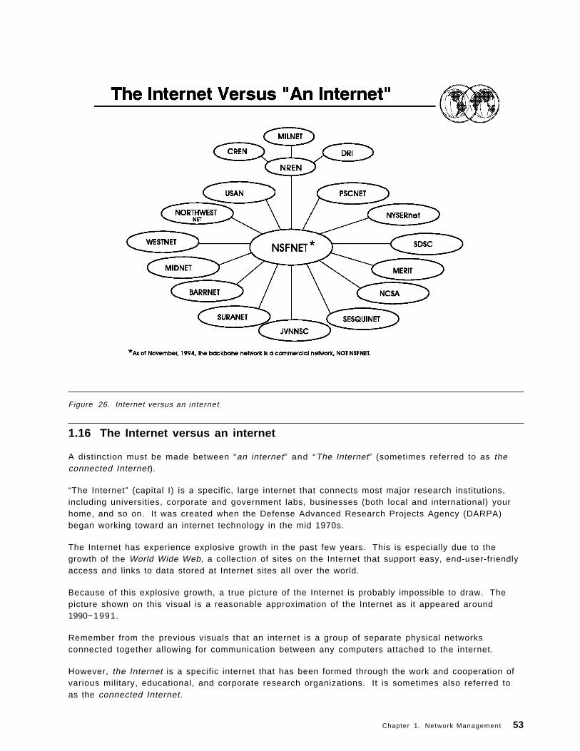
Figure 26. Internet versus an internet
1.16 The Internet versus an internet
A distinction must be made between “an internet” and “The Internet” (sometimes referred to as theconnected Internet).
“The Internet” (capital I) is a specific, large internet that connects most major research institutions,including universities, corporate and government labs, businesses (both local and international) yourhome, and so on. It was created when the Defense Advanced Research Projects Agency (DARPA)began working toward an internet technology in the mid 1970s.
The Internet has experience explosive growth in the past few years. This is especially due to thegrowth of the World Wide Web, a collection of sites on the Internet that support easy, end-user-friendlyaccess and links to data stored at Internet sites all over the world.
Because of this explosive growth, a true picture of the Internet is probably impossible to draw. Thepicture shown on this visual is a reasonable approximation of the Internet as it appeared around1990− 1 9 9 1 .
Remember from the previous visuals that an internet is a group of separate physical networksconnected together allowing for communication between any computers attached to the internet.
However, the Internet is a specific internet that has been formed through the work and cooperation ofvarious military, educational, and corporate research organizations. It is sometimes also referred toas the connected Internet.
Chapter 1. Network Management 53

The first pieces of the Internet came together around 1980, when DARPA first started converting itsmachines to use TCP/IP protocols. The ARPANET, DARPA′s packet-switching network that was alreadyin place, quickly became the backbone of the new Internet and was used for many early experimentswith TCP/IP. The transition to the Internet was completed in 1983 when TCP/IP became mandatory forconnections to the DARPA network, ARPANET.
The success of the TCP/IP technology and the Internet led other networks to adopt it. The NationalScience Foundation (NFS) took an active role in expanding the TCP/IP Internet to reach as manyscientists as possible. Starting in 1985, the NSF began a program to establish access networkscentered around its six supercomputer centers. In 1986 it expanded networking efforts by funding anew backbone network called the NSFNET, that reached all its supercomputer centers and tied them toARPANET, all becoming part of the Internet. Advances in technology caused the ARPANET to bedropped in favor of the NSFNET.
Today, the NSFNET backbone network is no longer supported by the National Science Foundation. It isinstead now a commercial network with installations all over the world.
• MILNET - Military network• CREN - Corporation for Research and Educational Networking—merger of CSNET (the
Computer+Science Network) and BITNET (the Because It′s Time Network)• DRI - Defense Research Internet• NREN - National Research and Education Network• NSFnet - The National Science Foundation network links the supercomputer sites to each other
through a high speed backbone. The network then interconnects to the many regional networksforming a network of networks. IBM, in a joint development project with MCI and Merit Inc.,provides software and switching system hardware for NSFnet.
• NYSERnet - New York State• JVNNSC - John von Neuman Center Consortium• SURANET - Southeastern Universities Regional Network• SDSC - San Diego State Consortium• MIDnet - Midwest Networks• BARRNET - Bay Area Regional Networks
54 ABCs of OS/390 System Programming

Figure 27. Internet guiding entities
1.17 Internet guiding entities
There are various organizations, or guiding entities, that provide the focus for the research anddevelopment of the Internet protocols, as listed here.
There are also “Requests for Comment” or RFCs that are reports of work, proposals for protocols, andprotocol standards.
The various Internet guiding entities are listed on this visual. These entities include:
• The Internet Activities Board (IAB) which provides the focus for most of the Internet Research andDevelopment. The IAB consists of:
− Internet Engineering Task Force (IETF) which is comprised of the Internet Engineering SteeringGroup (IESG) and members who make up the working groups in each of eight areas. The IETFconcentrates on short-term or medium-term engineering problems.
− Internet Research Task Force (IRTF) which is comprised of the Internet Research SteeringGroup (IRSG) and members who make up the research groups. The IRTF coordinates researchactivities related to TCP/IP protocols or internet architecture in general.
• The Network Information Center (NIC) which is run by SRI International under contract and isresponsible for the assignment of network addresses. The NIC also maintains and distributesinformation about TCP/IP and the connected Internet.
Chapter 1. Network Management 55

Requests For Comments (RFC) contain Internet standards and other useful information. They maybe long or short and may be wide or narrow in scope. The Network Information Center distributesthe RFCs to the community either electronically or in hard copy.
• The Network Operations Center (NOC) which manages key Internet networks, core gateways, anddoes network management on behalf of all users. The NOC is operated by MERIT, Inc. and isfunded by NSF. It is located in Ann Arbor, Michigan, USA.
56 ABCs of OS/390 System Programming

Figure 28. Internet addressing
1.17.1 Internet addressing
Because of the ability to interconnect computers across multiple networks, an appropriate addressingscheme was designed along with the networking protocols. All users of the network (includingapplications) are located at hosts. “Host” means any computer, whether it be a large system, a smallPC, or anything in between.
Each host must have an unique address to communicate with other hosts on the same internet. Aninternet address contains 32 bits and is divided into four octets (8 bits each). The address consists oftwo major parts:
• A network address - used to address a specific network in an internet
• A host address - used to address a specific host within a network
The two major parts of the internet address are often shown as follows:
in te rne t address = <network address><host address>
The internet address can be represented in a dotted-decimal form, where each octet is denoted as thedecimal representation of the binary octet.
As you can see in the visual, a sample 32-bit address is shown:
10000100 00001101 00001110 00000010
Chapter 1. Network Management 57

However, humans have a difficult time interpreting a 32-bit binary address. Therefore, adotted-decimal form of notation is used to represent an internet address. So the binary number shownabove becomes:
132.13.14.2
As mentioned before, an IP internet address consists of two parts; the <network address> and the<hos t add ress> . Depending on the number of octets used to represent the <network address> partof the internet address, there are four main classes of internet addresses. We will discuss those onthe next visual.
The important thing to remember is that each host on an internet must have a unique internet addressto be attached to the internet. If a host is on a private internet, then the group who manages access tothat internet must be consulted for a unique address. If you wish to connect a host to the Internet, thenyou must have the NIC assign the <network address> part of your internet address to be assured ofa unique address on the Internet.
58 ABCs of OS/390 System Programming

Figure 29. Internet address classes
1.17.2 IP address classes
Each IP internet address is a pair of addresses (<network address><host address>), where<network address> identif ies a network, and <host address> identif ies a specif ic host on thatnetwork. Each host attached to the same physical network has the same <network address>.
• The <network address> portion of an internet address is assigned by a central authority. In thecase of the Internet, the NIC must assign the <network address> part of the Internet address.This <network address> must be unique throughout the big Internet.
• The <host address> is assigned by the local authority and must be unique within the specificnetwork.
The number of bits in an internet address that are assigned to the <network address> part arevariable, resulting in four main classes of networks:
• Class A networks are very large networks (many hosts)• Class B networks are moderately large networks• Class C networks are small networks (256 or less hosts)• Class D addresses are used for ′multicast ′ addresses
For the four classes mentioned above the division between the <network address> and the <hostaddress> is :
Chapter 1. Network Management 59

• Class A allows seven bits of the internet address to be used for the <network address> portion;and the remaining 24 bits to be used for the hosts in the network. It allows for a total of 128different networks with 16.777.216 hosts in each network.
• Class B allows 14 bits of the internet address to be used for the <network address> portion; andthe remaining 16 bits to be used for the hosts in the network. It allows for a total of 16.384 differentnetworks with 65.536 hosts in each network.
• Class C allows 21 bits of the internet address to be used for the <network address> portion; andthe remaining eight bits to be used for the hosts in the network. It allows for a total of 2.097.152different networks with 256 hosts in each network.
• Class D is used for “multicast” address (limited broadcast addresses).
When hosts are moved from one network to another they must have the network address portion oftheir internet address changed and will probably also require a change in the host address portion oftheir internet address.
Address nuances:
• The <host address> is never set to zero, so an address with host address equal to zero refers tothe network itself. For example
The IBM network is 9.0.0.0
Further convention: eliminate trailing zeros in dotted-decimal notation, so the IBM network isoften written as simply 9.
• A <host address> of all ones is a broadcast address (on the local network).
• A <network address> of 0 is taken to mean “this network.”
60 ABCs of OS/390 System Programming

Figure 30. Subnetwork addressing
1.17.3 Subnetwork addressing
Subnetwork addressing allows large networks to be broken into smaller networks called subnets.
Where:
• Subnets are implemented by maintaining the integrity of the <network address> portion of theinternet address, but dividing the <host address> portion into two separate parts:
− Subnetwork address (sometimes referred to as a “local network address”)
− Host Address
• The resulting IP address can then be represented as follows:
<ne twork add ress><subne twork add ress><hos t add ress>
When the IP addressing scheme was developed, the designers worked in the world of expensivemainframes. They planned for tens of networks with hundreds of hosts. They did not plan for tens ofthousands of small networks (LANs) with hundreds of thousands of personal computers. Growth in theconnected Internet is most apparent. A large number of trivial networks stresses the entire Internetdesign because it means:
• Large administrative overhead is required to manage network addresses.
• Routing tables in gateways are extremely large.
Chapter 1. Network Management 61

Therefore, the principle of assigned IP addresses is too inflexible to allow easy changes to localnetwork configurations. Those changes might be:
• A new type of physical network installed at a location
• Growth of the number of hosts (personal computers) requires splitting the local network into two ormore separate networks
• Growing distances require splitting a network into smaller networks with gateways between them
To avoid having to request additional IP network addresses for every change in a local network, theconcept of subnets was introduced. Subnets are an extension to the base IP addressing scheme thatconsiders a part of the <host address> to be a “ local network address” or <subnetwork address>.IP internet addresses are then interpreted as:
<ne twork address><subnetwork address><hos t address>
• The assignment of subnets can be done locally, as the whole local network still appears to be onIP network to the outside world.
• Divis ion of the or iginal <host address> part into a <subnetwork address> and <host address>part can be chosen freely by the local administrator. However, once it has been established, itmust be used consistently throughout the whole local network.
• Implementation of subnets requires that all the hosts have the IP code which supportssubnetworking.
We will discuss subnets in more detail when we discuss routing.
62 ABCs of OS/390 System Programming

Figure 31. Definitions
1.18 Network definitions
There are several ways to interconnect networks together. Bridges, routers, and gateways allinterconnect networks; however, each does so differently.
• Bridges
− A bridge connects networks at the Link Control Layer. It is protocol independent. It does nothave an IP addresses.
− Bridges connect networks, or segments of the same network, at a very low functional level.
− Portions of the link header and trailer may need to be changed, but most of the data in theframe is left unaltered.
− Bridges are the most efficient, since they operate at the Data Link Control layer and usuallyrequire the least amount of processing.
• Routers
− A router connects networks at the Network Layer. It is protocol dependent. In TCP/IP, a routeris often referred to as a gateway.
A TCP/IP router has an IP address for each network it is attached to.
− Routers are used to route frames (or packets as they are also called) from one network toanother.
Chapter 1. Network Management 63

− Routing requires changing one or more addresses, making decisions as to the best route orpath to take through the interconnected networks and possibly changing link headers andtrailers.
− Routers usually are less efficient than bridges, but more efficient than gateways.
− A source of confusion in the TCP/IP world is that computers which perform routing functionsare often referred to as “gateways.” A TCP/IP “gateway” is not a gateway as described below;it is a router.
• Gateways
− A gateway (non-TCP/IP gateway) connects networks of same or different protocols. It isprotocol dependent.
− Gateways are used to change protocols from one set to another. This usually means removingthe information from all the protocol envelopes and repackaging it in another set of protocolenvelopes.
− Gateways are the least efficient way to interconnect networks, but allow the interconnection ofnetworks with different protocol implementations.
TCP/IP “gateways” can connect networks with different physical implementations (for example, LANand X.25), as long as the same higher-level network implementation (that is, IP) is used.
Therefore TCP/IP gateways are in reality routers.
64 ABCs of OS/390 System Programming

Figure 32. Internet gateways
1.19 Internet gateways
TCP/IP can be found in many different types of networks, and, in fact was designed to support theinterconnection of these networks using what is known as the “gateway” function.
Internet gateways have more than one address; an address is used to represent the gateway on eachnetwork the gateway is attached to. TCP/IP hosts with addresses on more than one network are called“mult i -homed.”
TCP/IP gateways can connect networks with different physical implementations (for example, LAN andX.25) as long as the same higher-level network implementation, that is, IP is used. As mentionedearlier, the TCP/IP gateway function is really a “router” function. TCP/IP gateways perform theirrouting function based upon the destination <network address>, not the destinat ion <hostaddress> . Packets are routed through the network based upon their target <network address>. The<host address> portion of the internet address is ignored during inter-network routing.
Hosts and gateways know nothing about the subsequent routing. Routing is a basic gateway functionand part of the base IP code; it is available in any node running TCP/IP.
On the next two visuals we will take a brief look at basic and full-function gateways.
Chapter 1. Network Management 65

Figure 33. Basic gateways
1.19.1 Basic gateways
Basic gateways provide the function to connect two networks together. The gateway has limitedknowledge of the network; it only knows about the hosts on the networks to which it is connected.Remember that gateways are “multi-homed”—they have IP addresses on each network they areattached to.
Basic gateways support “direct routing” if the destination and source hosts are on the same physicalnetworks (same <network address>). Basic gateways also support “indirect routing” if thedestination and source hosts are on different networks (routing must be done via one or moregateways). Datagrams are simply routed to the next gateway along the path.
• A source host only needs to know the address of the first gateway.
• Each gateway will forward the packet until the destination network is reached; the packet is thensent using direct routing.
• In the example on the visual, a datagram from network 192.1.115 that is destined for network193.10.4 will be routed by gateway G1 to gateway G2.
Each host must keep an IP routing table which maps:
• Local addresses as direct routes.
• Off-network destination host addresses as indirect routes through a locally attached gateway.
• A default route for packets with a destination network address not listed in the routing table.
66 ABCs of OS/390 System Programming

Figure 34. Full-function gateways
1.19.2 Full-function gateways
Full-function gateways provide more sophisticated functions, where the gateway knows about allinterconnected networks. They maintain and update routing information dynamically to reflect networktopology changes.
Each gateway has information about:
• Networks that can be reached
• Number of hops to each network (gateway hops)
Here, for example Gateway A′s routing table is shown, with the information on reaching Networks 1, 2,3, and 4.
Full-function gateways are divided into two classes: core and non-core gateways.
• Core gateways are maintained by NIC and are used to interconnect major user networks toNSFNET.
• Non-core gateways are used to interconnect multiple user networks together.
Both core and non-core gateways must know about all of the networks they support. This isaccomplished using one of the different gateway protocols.
We will discuss the different gateway protocols on the next visual.
Chapter 1. Network Management 67

Figure 35. Gateway protocols
1.19.3 Gateway protocols
There are several protocols associated with the transfer of information between gateways (routers).The specific protocol(s) used are determined by the gateway type:
• Gateway-to-gateway protocol (GGP)
− Used to transfer information between “neighbor” gateways.− Each gateway will update its tables based upon the received information and will send
information about changes to its neighbors.− Information transferred includes the networks reachable by this gateway, and the path length
for reaching the networks.
• Exterior gateway protocol (EGP)
− Used to transfer information between “exterior” gateways. (Exterior gateways are ones thatconnect physical networks in different autonomous networks, where an autonomous network isa group of physical networks connected together and administered by a single authority.)
− The EGP protocol supports passing of route information as well as other dialogs between theexterior gateways.
− Exterior gateways collect information from interior gateways (gateways within an autonomousnetwork.
• Interior gateway protocols (IGP)
− A set of protocols used to transfer information between “interior” gateways.
68 ABCs of OS/390 System Programming

− Examples of IGP protocols include the Routing Information Protocol (RIP) and the HELLOprotocol.
− RIP is a class of protocols based upon the Xerox network XNS routing protocols.
Chapter 1. Network Management 69

Figure 36. Routing information protocol
1.20 Routing information protocol
Autonomous networks implement the RIP protocol. RIP or routing information protocol is a widelyused interior gateway protocol. It relies on physical network broadcasts to make routing exchangesquickly.
RIP routing tables consist of the distance to each physical network in the autonomous network that thegateway is aware of. The distance to that network is measured as the number of hops (gatewaysbetween the sending gateway and the network).
RIP partitions hosts in the autonomous network into active and passive (silent) machines. Activegateways advertise their routes to others; passive machines listen and update their routes based onadvertisements, but do not advertise. Typically, gateways run RIP in active mode, while hosts usepassive mode. The routing information that is broadcast is that of the sender of the broadcast. Activegateways broadcast their routing table every 30 seconds.
In this example, Gateway A sends Gateway B its current routing database, consisting of theinformation that Network 1 is 0 hops from A and Network 4 is 2 hops from A. Similarly, Gateway Bsends Gateway A and C, its current routing database, with the information that Network 1 is 1 hop fromB and Network 4 is 1 hop from B. Each gateway updates its routing database with the latestinformation that it receives.
A hop count of 15 denotes infinity, so as to avoid routing loops.
70 ABCs of OS/390 System Programming

RIP uses vector-distance routing for local networks. RIP is also known as route-d.
Chapter 1. Network Management 71

Figure 37. TCP/IP protocol suite
1.21 TCP/IP protocol suite
Remember that the TCP/IP protocol suite does not refer just to TCP and IP. It consists of:
• Application protocols, such as TELNET, FTP, SMTP, and others.
• The key inter-networking protocols:
− Transmission Control Protocol (TCP)
− the Internet Protocol (IP)
• Other networking protocols include User Datagram Protocol (UDP), Internet Control MessageProtocol (ICMP), Address Resolution Protocol (ARP), and so forth.
• The TCP/IP protocol suite also includes the Network Access Interface protocols, which are theinterface protocols for the underlying physical network.
In this subtopic, we will go into a little more detail about some of the TCP/IP protocols and what theyare used for. The purpose of this architecture review is to make sure you are familiar with the purposeof these protocols before we get into implementation specifics.
Remember that architecturally, TCP/IP is a layered architecture, consisting of a protocol stackcomprised of four basic layers as seen in this visual. They are:
• The application layer, with the application protocols, which provide applications that the users caninvoke to access network services. The application layer is built on the services of the transportlayer.
72 ABCs of OS/390 System Programming

Some of the application protocols are shown here. We will cover these in more detail in the sectionon TCP/IP Applications.
• The transport layer consisting of the two different protocols: User Datagram Protocol (UDP) andTransmission Control Protocol (TCP)—TCP and UDP. TCP is a connection oriented protocol,whereas UDP is a connection-less protocol.
• The internet layer consisting of the protocols Internet Protocol (IP), Internet Control MessageProtocol (ICMP), Address Resolution Protocol (ARP), Routing Information Protocol (RIP), andReverse Address Resolution Protocol (RARP).
IP is a connection-less protocol.
• The data link or physical layer with protocols such as Ethernet, X.25, Token Ring, and so forth.
First, we will discuss the concept of protocol layering in the next visual and then over the next series ofvisuals we will provide an overview of the TCP/IP layers and the protocols at each layer.
Chapter 1. Network Management 73

Figure 38. Protocol layers
1.21.1 Protocol layers
Each separate layer of a layered protocol is responsible for adding its own headers (and sometimestrailers) for successful peer-to-peer communication with the same layer in a protocol stack in adifferent machine. Each layer “N” passes transparently the information it receives from the nexthigher layer “N+1” after it adds the required headers (and trailers, if required). A layer “N” ProtocolData Unit (PDU) is simply a layer “N+1” Service Data Unit (SDU) plus the required layer “N” headers.
As you can see from the visual, the TCP/IP protocol suite has different names to describe the PDUscreated at each layer.
The operation of layered protocols is based on a fundamental idea called the “layering” principle. Itcan be described as follows:
Layered protocols are designed so that layer “N” at the destination receives exactly the sameobject sent by layer “N” at the source.
The layering principle explains why layering is such a powerful idea. It allows the protocol designer tofocus attention on one layer at a time, without worrying about how lower layers perform. Also, asenhancements and advances are made to both software and hardware, a specific item in a protocolstack can be improved without having to completely replace all the protocol software/hardware in anetwork.
• The layer N Protocol Data Unit (PDU) = Layer N+1 Service Data Unit (SDU) + layer N headers.
• TCP PDUs are called segments.
74 ABCs of OS/390 System Programming

• IP PDUs are called datagrams, in recognition of IP Connectionless Orientation.
Depending on the requirements of the underlying physical network, IP may further dividedatagrams into fragments, each carrying a replica of the IP header. These fragments will be lessthan or equal to the maximum size of the physical data unit supported by the physical network.
• PDUs for the Network Access Layer(s) depend upon the type of network utilized:
− X.25 PDUs are called packets.
− Data Link PDUs are called frames.
Within a layered protocol such as TCP/IP, each layer invokes the services of the layer below it whileproviding services to the layer above it. The commands and responses between the layers of aprotocol stack are called primitives and are distinct from the flow of peer-to-peer information describedabove (PDUs, segments, datagrams, and so forth).
Chapter 1. Network Management 75
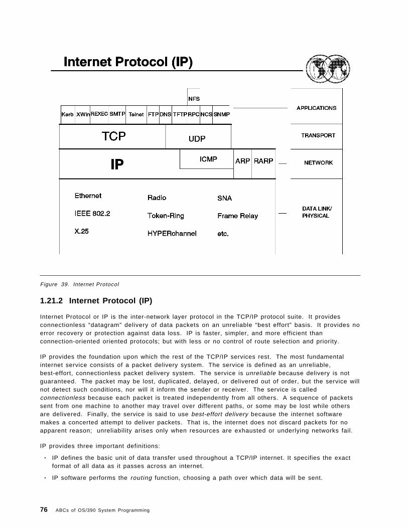
Figure 39. Internet Protocol
1.21.2 Internet Protocol (IP)
Internet Protocol or IP is the inter-network layer protocol in the TCP/IP protocol suite. It providesconnectionless “datagram” delivery of data packets on an unreliable “best effort” basis. It provides noerror recovery or protection against data loss. IP is faster, simpler, and more efficient thanconnection-oriented oriented protocols; but with less or no control of route selection and priority.
IP provides the foundation upon which the rest of the TCP/IP services rest. The most fundamentalinternet service consists of a packet delivery system. The service is defined as an unreliable,best-effort, connectionless packet delivery system. The service is unreliable because delivery is notguaranteed. The packet may be lost, duplicated, delayed, or delivered out of order, but the service willnot detect such conditions, nor will it inform the sender or receiver. The service is calledconnectionless because each packet is treated independently from all others. A sequence of packetssent from one machine to another may travel over different paths, or some may be lost while othersare delivered. Finally, the service is said to use best-effort delivery because the internet softwaremakes a concerted attempt to deliver packets. That is, the internet does not discard packets for noapparent reason; unreliability arises only when resources are exhausted or underlying networks fail.
IP provides three important definitions:
• IP defines the basic unit of data transfer used throughout a TCP/IP internet. It specifies the exactformat of all data as it passes across an internet.
• IP software performs the routing function, choosing a path over which data will be sent.
76 ABCs of OS/390 System Programming

• IP includes a set of rules that define the unreliable packet delivery. The rules define how hostsand gateways should process packets, how and when error messages should be generated, andthe conditions under which packets can be discarded.
The data travels across the network in “packets.” The basic packet used to move information is calledthe IP datagram. Since IP is a connectionless protocol, it does not provide delivery verification,guaranteed sequential delivery of packets, or error recovery. All these functions will be theresponsibility of some higher-level function, such as TCP or an application.
Because of the underlying physical network limitations, IP will sometimes have to fragment a packet.
• IP expects all physical sub-networks to be able to support a packet size of at least 576 bytes.
• Data packets are assigned a unique identification number prior to fragmentation.
• When the packets are fragmented, each is sent with an offset value.
• The receiving IP can reassemble the packet using the identification number and the offset values.
Chapter 1. Network Management 77

Figure 40. IP datagrams
1.21.3 IP datagrams
An IP datagram consists of:
• Header
The header is built by IP using the data received from the next higher layer along with “primitives”from the next higher layer giving additional information on how to handle the data.
• Data
Data is made up of information that is received from the next higher layer, or information receivedfrom the network that is passed up from the physical layer.
Some of the fields contained in the IP header include:
• The version of IP being used.• Length of the IP header and total packet.• Identification number (and offset values if fragmentation is being used).• Higher level protocol (for example, TCP) to which IP should deliver the packet.• Source and destination IP address.
When the IP datagram fields are completed, the packet is passed to the DLC layer where it is furtherenveloped.
At the destination host, IP reassembles the fragments (if any), removes the IP headers and delivers theoriginal segments to the correct high-level protocol (TCP, UDP, and so forth).
78 ABCs of OS/390 System Programming

Segments are delivered to the higher layer in whatever order they are received.
Chapter 1. Network Management 79

Figure 41. ICMP
1.21.4 Internet Control Message Protocol (ICMP)
The Internet Control Message Protocol allows hosts and gateways to send error or control messagesto other hosts or gateways. It provides communications between the internet software on one machinewith the internet software on another machine.
ICMP messages travel across the network encapsulated in the data portion of IP datagrams. There isno added reliability, therefore the messages themselves may be lost or discarded (IP isconnectionless).
ICMP is a required part of IP, and cannot be considered a higher-level protocol.
The final destination of an ICMP message is the IP software itself on the destination machine.Therefore, the ICMP error message is handled by the IP software and not sent to the applicationprogram. However, if ICMP determines that a particular higher-level protocol or application programhas caused a problem, it will inform the appropriate module. ICMP messages are of various types,some of the types include:
• Echo request and reply (Packet InterNet Groper - PING)• Destination unreachable• Redirect (change a route)• Time exceeded for a datagram• Time stamping request/reply• Overrun conditions• Information (address) request/reply
80 ABCs of OS/390 System Programming

So ICMP is used for basic error reporting (not correction) between two hosts at the inter-network level,and is an integral part of the Internet Protocol (IP) that handles error and control messages.
The intent of ICMP is to support some level of error reporting, not to address every error situation. Inother words, ICMP does not relieve the upper-level protocols from the responsibility of ensuring errorfree data.
Chapter 1. Network Management 81

Figure 42. Address nuances
1.21.5 Address nuances
The problem:
• Hosts in an IP network are known by their 32-bit internet address.
• Networks need to know the physical network address of hosts to allow communication betweenhosts on the network.
Therefore, some mechanism is required to translate a 32-bit internet host address to the hardwareaddress for that host on its physical network.
Remember that each host in an internet must have a unique 32-bit IP address. Also remember that aninternet may consist of many different kinds of physical networks. Each one of these physical networksmay have a different method of physical hardware addressing for the hosts on that network. Ingeneral, the hardware address for a host on a network is much different from the 32-bit softwareaddress used by IP for software running on that host.
We need to address the problem of mapping internet addresses (software addresses) to the actualphysical hardware addresses.
One option is to set the host IP address equal to the physical network address. However, this does notwork because in some cases:
• Physical address length exceed the host internet address• Physical address can change. (for example, Ethernet)
82 ABCs of OS/390 System Programming

The solution could be either:
• Simple algorithms to translate software IP addresses to hardware addresses• Address Resolution Protocol (ARP)• A mapping table• Reverse Address Resolution Protocol (RARP)• Proxy ARP
We will discuss ARP, RARP, and ProxyARP in greater detail.
Chapter 1. Network Management 83

Figure 43. Address Resolution Protocol (ARP)
1.21.6 Address Resolution Protocol (ARP)
The Address Resolution Protocol, ARP, allows a host to find the physical address of a target host onthe same physical network given only the target host′s IP address.
• The basic notion behind ARP is:− The sending host broadcasts a packet containing the target internet address to all the stations
on the local network.− All stations on the local network receive the packet.− The correct station will send back a reply identifying its local network address.
Suppose a host (source) wants to send a packet to another host (destination) on the same physicalnetwork. The source host will turn the packet over to IP. The IP routing function will attempt to matchthe destination IP address to a physical address.
Nodes supporting the ARP function will maintain a table that equates IP addresses to physicaladdresses. Packets containing an IP address that is not in the table (also called the ARP “cache”) willresult in an ARP broadcast being sent across the physical (local) network in an attempt to locate theaddress. A host recognizing its IP address in the ARP packet will respond allowing the originator ofthe broadcast to identify the physical address of the destination. (This is similar to the way NETBIOSworks.)
Some refinements to ARP include:
• “Caching” of address resolution information.
84 ABCs of OS/390 System Programming

• Utilization by all stations of information contained in the special broadcast packet.
Chapter 1. Network Management 85

An ARP packet contains information such as:
• Type of hardware and protocol being used (for example, Ethernet).• Source and target IP address (32 bits).• Source and target hardware (physical) address (48 bits).
An important advantage of the ARP process is that it is dynamic—no tables are maintained by systemsprogrammers.
86 ABCs of OS/390 System Programming

Figure 44. Reverse Address Resolution Protocol (RARP)
1.21.7 Reverse Address Resolution Protocol (RARP)
There are some kinds of workstations referred to as “diskless workstations.” They have no access tosecondary storage, and therefore cannot store an IP address for use to communicate with other hostson an internet. A method is required that allows a workstation that knows its hardware address toacquire an internet address.
The basic notion behind RARP is:
• How to determine the internet address given a physical address.
The RARP process works as follows:
• The host diskless workstation (source) sends a broadcast request to special RARP server(s). Thehost workstation probably does not know the IP address of the RARP server, so it sends itsbroadcast request at the physical address level to all machines on its local network.
The broadcast request includes the physical address of the host workstation.
• Only machines authorized to supply the RARP services process the request and send a reply. TheRARP server will have a pre-defined mapping table to support this function. It receives thebroadcast request and searches its tables for the IP address that matches the physical addressreceived in the broadcast request. The RARP server then responds to the requestor with therequired internet address.
• This requires the specific function of an RARP server in the network.
• The contents of the RARP packet are very similar to the ARP packet.
Chapter 1. Network Management 87

Figure 45. Proxy ARP
1.21.8 Proxy ARP
The goal of Proxy ARP is to allow multiple physical networks to share a single internet <networkaddress> and thereby simplify internet routing and administration. In the visual above, note that thereare two separate physical networks joined by gateway 163.10.1.4. Also note that the <networkaddress> for all the hosts on both networks is 163.10.1!
Proxy ARP works on a network that uses ARP to do the internet-to-physical address translation. In thisexample, the MAIN NETWORK is the original network and the SECONDARY NETWORK was added at alater date. The gateway “G” connecting the two networks uses ARP to maintain the illusion that onlyone network exists. To make the illusion work, G keeps the location of hosts completely hidden,allowing all other machines on the network to communicate as if directly connected.
• H1 (163.10.1.1) has an IP datagram destined for H8 (163.10.1.8).
• H1 invokes ARP to map H8′s IP address to a physical address.
• Because gateway “G” runs proxy ARP software, it captures the broadcast ARP and responds withits (the gateway′s) local network address, hence it assumes the proxy role.
• H1 receives the ARP response and installs the mapping in its ARP cache.
• H1 sends the datagram that is destined for H8, but actually sends it to gateway “G.”
• When G receives a datagram, is searches a special routing table to determine how to route thedatagram.
• G forwards the datagram destined for H8 over the secondary network.
88 ABCs of OS/390 System Programming

To allow hosts on the secondary network to reach hosts on the main network, G performs the proxyARP service on that network as well. Proxy ARP is good only in limited configurations.
Chapter 1. Network Management 89

Figure 46. Domain Name System
1.22 Domain Name System
It is difficult for a user to remember the 32-bit IP address for each host that the user may requirecommunications with. The use of symbolic high-level machine names makes it much easier for usersto remember host names and establish communications with applications running on many differentTCP/IP hosts.
As the acceptance and use of TCP/IP grew, the use of numeric IP addresses was replaced by the useof symbolic names. Initially, host names-to-address mappings were maintained by the NetworkInformation Center (NIC) in a single file which was fetched by all hosts using the File Transfer Program(FTP). Due to rapid growth in the number of hosts on the Connected Internet, this mechanism becametoo slow and inefficient and was replaced by the Domain Name System.
• Domain names, like IP addresses, are concatenated. For example nm1.nm2.nm3.
• The Domain Name System is used to structure network names in a hierarchical fashion. Thismeans that the Internet is divided into hierarchical domains.
• In this system, and shown in this visual, the highest level domain (below the unnamed root) is amajor network type. For example, as seen here COM is the highest level domain for commercialorganizations and EDU is the highest level domain for educational institutions.
The top-level domain namespace is partitioned by the Internet authority. The current top-levelnames are:
90 ABCs of OS/390 System Programming

Domain Name Meaningedu Educational institutionscom Commercial organizationsgov Government institutionsmil Military groups
net Major network support centers org Organizations other than those above arpa Temporary ARPANET domain (obsolete) * int Internation organizations country code International standard two-letter identifier
• The next level represents major networks within a network type. In this example, IBM is a majornetwork within the COM or commercial organizations domain.
• At the next level, the network domains are divided into individual networks, such as networkRALEIGH shown here.
• The network name is a concatenation of various domain names.
• In this example, the name VM9.RALEIGH.IBM.COM represents a host, VM9 on the networkRALEIGH, which is a domain on the IBM network, which is connected to the top level networkCOM.
An important feature of the Domain Name System to remember is that the Internet authority isresponsible for partitioning and naming only the top level domain namespace. Authority for namesand partitioning at the lower levels is the responsibility of the designated agent at that level Forexample, IBM might choose to partition its namespace based on site name and to delegate to each siteresponsibility for maintaining names within its partition (an administrative group at RALEIGH would beresponsible for names and further subdivision within its location). The idea is to keep subdividing thenamespace until each subdivision is small enough to be manageable. The topmost level (the Internetauthority) divides the namespace and delegates authority for each division; it is not bothered bychanges within one division.
For these reasons, the TCP/IP Domain Name System naming scheme allows delegation of authority forthe hierarchical namespace without regard to physical connections.
Now we must have some way of mapping the names maintained by the Domain Name System to theactual IP addresses of the hosts. This function is performed by cooperative systems called nameservers.
Chapter 1. Network Management 91
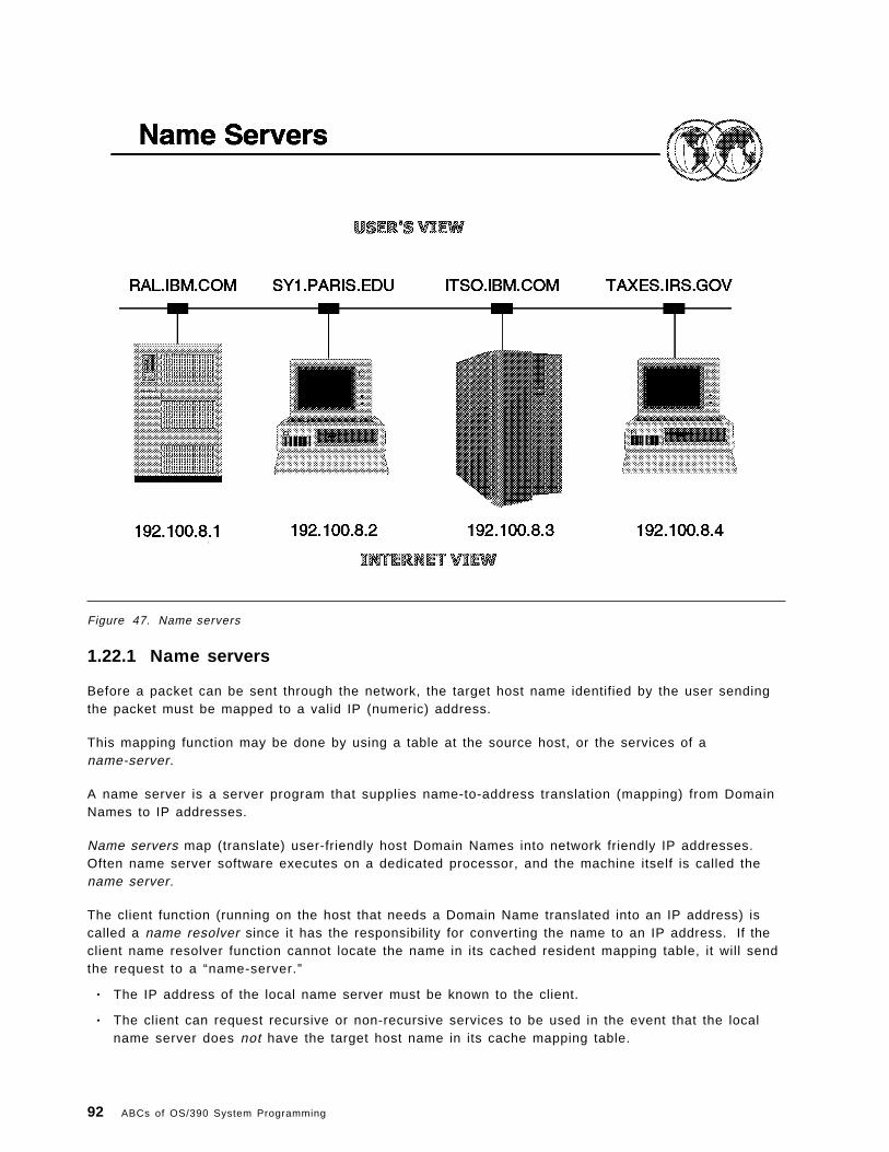
Figure 47. Name servers
1.22.1 Name servers
Before a packet can be sent through the network, the target host name identified by the user sendingthe packet must be mapped to a valid IP (numeric) address.
This mapping function may be done by using a table at the source host, or the services of aname-server.
A name server is a server program that supplies name-to-address translation (mapping) from DomainNames to IP addresses.
Name servers map (translate) user-friendly host Domain Names into network friendly IP addresses.Often name server software executes on a dedicated processor, and the machine itself is called thename server.
The client function (running on the host that needs a Domain Name translated into an IP address) iscalled a name resolver since it has the responsibility for converting the name to an IP address. If theclient name resolver function cannot locate the name in its cached resident mapping table, it will sendthe request to a “name-server.”
• The IP address of the local name server must be known to the client.
• The client can request recursive or non-recursive services to be used in the event that the localname server does not have the target host name in its cache mapping table.
92 ABCs of OS/390 System Programming

− Recursive service means that the local name server will contact other name servers and reportthe results back to the client (IP address or a negative response).
− Non-recursive service means that the local name server will return the IP addresses of othername servers back to the client; the client must then contact them directly.
• In the interest of efficiency, name servers cache resolved names to improve the overallperformance of the name server system. Each entry has a separate time-to-live so that after thespecified amount of time, the entry will be deleted and the name server must go back to theauthoritative source to update its cache entry.
Another protocol called the “Domain Protocol” is used for communicating between the domains.Domain protocol messages can be sent using either TCP or UDP.
Chapter 1. Network Management 93

Figure 48. Ports and sockets
1.23 Ports and sockets
Each host has one or more “processes” (applications) that have a need to communicate withprocesses on other hosts (an example of a process is an application such as TELNET). In order to usethe functions of TCP/IP, each process must identify itself to TCP by one or more ports.
A port or ports may be thought of as a logical connection point that TCP uses to distinguish amongmultiple processes within a given host computer. Therefore ports can be thought of as processaddresses used by TCP. Sockets are a concatenation of a port number and an internet address.
So a process (application) utilizing TCP is associated with a particular TCP port . The port number isselected when a process begins communications with TCP (OPEN primitive). This port provides accessto and from TCP and any process or application in the same host or a different host. A port is a 16-bitnumber used by the host-to-host protocol (TCP) to identify to which higher-level protocol or applicationprogram (process) it must deliver incoming messages.
• A TCP port corresponds to the Service Access Point (SAP)
• Some commonly used processes or applications (for example, TELNET, FTP, and so forth) willalways use the same port number. These ports used by these processes are termed “well-known”ports.
The range of well-known port numbers is between 0 and 255. User applications should use portnumbers above this range. Different user-written applications can request an available port fromTCP/IP, avoiding any confusion that might occur if two applications request the same port number.
94 ABCs of OS/390 System Programming

Ports are used by both TCP and UDP.
Processes are known to the network by a concatenation of their port address and the IP address. Thistotal identifier is also called a “socket” or a “socket address.”
Chapter 1. Network Management 95

Figure 49. TCP/IP transport layer protocols
1.24 Transport layer protocols
The primary duty of the transport layer is to provide communication from one application program toanother. Such communication is often called end-to-end. The transport layer may regulate the flow ofinformation. It may also provide reliable transport, ensuring that data arrives without error and insequence. To do so, it arranges to have the receiving side send back acknowledgements, and itretransmits lost packets. The transport software divides the stream of data being transmitted intosmall pieces (called packets in the ISO terminology and segments by TCP/IP) and passes each packet,along with a destination address, to the next layer (IP) for transmission.
A general purpose computer can have multiple application programs accessing an internet at onetime. The transport layer must accept data from several user programs (processes) and send it to thenext lower layer. To do so, it adds additional information to each packet, including codes (portnumbers) that identify which application program should receive it, as well as a checksum. Thereceiving machine uses the checksum to verify that the packet arrived intact, and uses the destinationcode (port number) to identify the application program to which it should be delivered.
The two protocols at the TCP/IP transport layer are TCP and UDP.
• TCP is a connection-oriented protocol. Before transferring data, a connection is established withthe destination node. When data transfer is ended, the connection is terminated. This process isanalogous to making a telephone call, where connections are established, with the partner beforethere is an exchange of information. Hence, TCP is a connection-oriented protocol.
96 ABCs of OS/390 System Programming

• UDP is a connection-less protocol. No connection is established prior to the transfer of data. Thedata is sent into the network and is assumed to reach the destination. This process is similar tothe mailing of a letter, where the letter reaches the destination, without a connection beingestablished between the origin and destination.
UDP provides a procedure for application programs to send data to other programs with a minimum ofprotocol intervention. UDP data is sent in the form of packets or “datagrams.” UDP provides anunreliable mode of communication between the source and destination hosts. UDP does not offer aguarantee of datagram delivery or duplication protection.
Applications that require reliable delivery or streams of data should use TCP.
Chapter 1. Network Management 97

Figure 50. TCP
1.24.1 Transmission Control Protocol (TCP)
TCP is a transport layer protocol that provides connection type services, including reliability, flowcontrol, and error recovery between pairs of processes (applications). It does not assume reliabilityfrom the lower-level protocols (such as IP), so TCP must guarantee this itself.
A connection represents a logical circuit between two sockets. This logical connection must beestablished prior to data flow.
TCP takes care of segmentation of the data as required by the lower-level network functions. It can becharacterized by the following facilities it provides for the applications (processes) using it:
• Stream data transfer
From the application′s point of view, TCP transfers a contiguous stream of bytes through theinternet. The application does not have to bother with chopping the data into basic blocks ordatagrams. TCP does this by grouping the bytes into TCP segments which are passed to IP fortransmission to the destination. Also, TCP decides how to segment the data and it may forwardthe data at its own convenience.
• Reliability
TCP assigns a sequence number to each byte transmitted, and expects a positive acknowledgment(ACK) from the receiving TCP. If the ACK is not received within a timeout interval, the data isretransmitted. As the data is transmitted in blocks (TCP segments), only the sequence number ofthe first data byte in the segment is sent to the destination host.
98 ABCs of OS/390 System Programming

The receiving TCP uses the sequence numbers to rearrange the segments when they arrive out oforder, and to eliminate duplicate segments.
Chapter 1. Network Management 99

• Flow control
The receiving TCP, when sending an ACK back to the sender, also indicates to the sender thenumber of bytes it can receive beyond the last received TCP segment, without causing overrun andoverflow in its internal buffers. This is sent in the ACK in the form of the highest sequence numberit can receive without problems. This mechanism is also referred to as a window-mechanism.
• Window size
Window size is set when the connection is established, but will change dynamically during datatransfer.
• Error recovery
Error recovery is done using byte sequencing; the receiver sends an acknowledgement indicatingthe last byte number successfully received; the sender will then retransmit any bytes (in the formof packets) not yet acknowledged.
Once an error-packet is received, the receiver will stop counting even if the following packets arereceived error free.
• Time outs
TCP has the ability to adjust time-out values related to data transmission by examining the time ittakes for an acknowledgement to be returned for packets sent (round-trip delay).
How TCP reacts to time-out and error conditions will be determined by how each host (user)implements error recovery.
• Multiplexing
Multiplexing is achieved through the use of ports.
• Logical connections
The reliability and flow-control mechanisms described above require that TCPs initialize andmaintain certain status information for each “data stream.” The combination of this status,including sockets, sequence numbers, and window-sizes is called a logical connection (or virtualcircuit). Each connection is uniquely identified by the pair of sockets used by the sending andreceiving processes (applications).
100 ABCs of OS/390 System Programming

Figure 51. TCP segment
1.24.1.1 TCP segment
TCP takes the data from the higher level application and adds its header information. The resultingprotocol data unit (PDU) is called a TCP segment.
Remember that TCP will block bytes received from an application into segments and include thesequence number of the first data byte included in the segment as part of the TCP header (sequencenumber field).
• TCP segments contain a TCP header followed by unaltered application data that has been blockedinto segments as required by the network.
Some of the fields contained in the TCP header include:
− 16-bit source and destination port numbers.
− Byte sequence numbers - the sequence number of the first data byte in this segment.
− Acknowledgement number - if the ACK control bit is set (in the Flags field), this field containsthe value of the next sequence number that the receiver is expecting to receive.
− Window value - used in ACK segments, it specifies the number of data bytes (beginning withthe one indicated in the acknowledgment number field) which the receiver is willing to accept.
− Checksum for the TCP header.
− Flags - urgent pointer flag, acknowledgement flag, and so forth.
− User data - data received from the application.
Chapter 1. Network Management 101

Figure 52. User Datagram Protocol (UDP)
1.24.2 User Datagram Protocol (UDP)
UDP or User Datagram Protocol provides the interface between ports and IP for connectionless datatransfer (that is, using datagrams).
• UDP is an alternative protocol to TCP at the transport layer.
• UDP provides no error recovery, flow control, or reliability.
• UDP will receive the information from a port (process or application) and envelope it in a UDPdatagram.
• The UDP datagram contains the application data along with the source and target port addresses,a length value and a header checksum value.
• There are some TCP/IP applications that use the UDP protocol (for example, Simple NetworkManagement Protocol (SNMP), Trivial File Transfer Protocol (TFTP), and so forth).
UDP uses the underlying Internet Protocol to transport a message from one machine to another, andprovides the same unreliable, connectionless datagram delivery semantics as IP. It does not useacknowledgements to make sure messages arrive, it does not order incoming messages, and it doesnot provide feedback to control the rate at which information flow between the machines. Thus, UDPmessages can be lost, duplicated, or arrive out of order. Furthermore, packets can arrive faster thanthe recipient can process them. In summary:
102 ABCs of OS/390 System Programming
The User Datagram Protocol (UDP) provides unreliable connectionless delivery service using IP totransport messages between machines. It adds the ability to distinguish among multiple destinations(PORTS) within a given host computer.
The ability to distinguish among multiple applications uses the same port concept that was discussedon previous visuals. Each UDP message contains two 16-bit port numbers (send and receive ports) inthe header. As described earlier, some of these ports may be “well known” and permanently reservedfor specific applications (for example, TFTP uses port 69).
An application program that uses UDP accepts full responsibility for handling the problem of reliability,including message loss, duplication delay, out-of-order delivery, and loss of connectivity.
UDP is a small protocol in the sense that it does not add much to the semantics of IP. It merelyprovides application programs with the ability to communicate using the unreliable, connectionless,packet delivery service.
Chapter 1. Network Management 103

Figure 53. TCP/IP clients and servers
1.25 Clients and servers
TCP is a peer-to-peer, connection-oriented protocol. There is no master/slave relation between hosts.Applications running on those hosts, however, usually use a client-server model for communications.
• A server is a process or application that provides a service to other users (applications) in thenetwork.
• A client is a “requestor” of a service.
A client-server type of application consists of both a server and a client part, which can run on thesame or on different systems.
• Like more and more of todays network implementations, TCP/IP uses a “client-server” model forcommunications between applications.
• Users usually invoke the client part of the application to create a request. The request is then sentby the client code to the server. TCP/IP is the transport vehicle. The server then performs therequested function and sends replies to the client. A server can usually deal with multiplerequests (multiple clients) at the same time.
• Some servers (that is, the more popular TCP/IP applications such as FTP, TELNET, an so forth)provide their services through “well-known” ports.
• Server functions require considerably more code than do client functions; TCP/IP productsproviding support for the various applications may provide only the client function, only the serverfunction, or both.
104 ABCs of OS/390 System Programming

Figure 54. TCP/IP Application Layer Protocol
1.26 TCP/IP Application Layer Protocol
In addition to the Network and Transport layer protocols, the TCP/IP protocol suite includes a numberof higher level protocols, called “applications or processes.” Functionally, they provide services suchas file transfer, messaging, and virtual terminal support. These applications interface to TCP (or UDP)and are all optional. Inclusion of support for specific applications varies widely from vendor to vendor.
Chapter 1. Network Management 105

Figure 55. TELNET
1.26.1 TELNET: an illustration
TELNET provides a standardized interface to allow a process (application) at one host (using theTELNET client function) to access a process (application) at another host (using the TELNET serverfunction) as if the client was a local terminal directly connected to the remote host.
TELNET performs this function by offering three basic services:
• It defines a network virtual terminal to provide a standard interface to remote systems.
• It allows the client and server to negotiate options for terminal characteristics.
• TELNET treats both ends of the connection the same way—the client side is not required to be auser ′s terminal, it could be a program instead. Either end can negotiate options.
TELNET does not provide graphics capabilities.
TELNET is a simple remote terminal protocol. It allows a user at one site to establish a TCPconnection to a login server at another site, and then it passes keystrokes from the user ′s terminaldirectly to the remote machine as if they had been typed at a terminal on the remote machine.TELNET also carries output from the remote machine back to the user′s terminal. The service is calledtransparent because it gives the appearance that the user′s terminal attaches directly to the remotemachine.
Typically, the TELNET server function handles multiple, concurrent connections from TELNET clientsanywhere in the IP network.
106 ABCs of OS/390 System Programming

To make TELNET interoperate between as many systems as possible, it must accommodate the detailsof many different kinds of computers and operating systems. For example, some systems require linesof text to be terminated by the ASCII carriage control character. Others require the ASCII line-feedcharacter. In addition, most systems provide a way for a user logged in to an ordinary terminal tointerrupt a running program. However, the keystroke used to generate the interrupt varies fromsystem to system.
Therefore, TELNET defines how data and command sequences are sent across the internet. Thedefinition is know as the network virtual terminal (NVT). An NVT is an imaginary device, providing thenecessary basic structure of a standard terminal. Each host maps its own terminal characteristics tothis NVT, and assumes that every other host will do the same.
The TELNET protocol also supports the principle of negotiated options. This is because many hostsmay wish to provide additional services beyond those available with the NVT. Various options may benegotiated between the client and server during the connection process. The server and client use aset of conventions to establish the operational characteristics of their specific TELNET connection viathe “DO, DON′T, WILL, WON′T” mechanism:
• WILL - will you agree to let me use option X• WON′T - I will not use option X• DO - I do agree to let you use option X• DON′T - I do not agree to let you use option X
Examples of some of these options are:
• Support for specific terminal types (for example, 3278-2 type)• Window sizes• Translate table selection• Full-screen formatting• Support for echoing
Chapter 1. Network Management 107

Figure 56. Simple Mail Transfer Protocol
1.26.2 Simple Mail Transfer Protocol (SMTP)
SMTP is an electronic mail protocol that provides support for message and note exchanges betweenusers on the same or different hosts.
Two main standards define SMTP:
1. A standard on the format of the mail messages which deals with the layout and contents of themail envelope (RFC 822).
2. A standard for the exchange of mail between two computers which specifies the protocol used tosend mail to another SMTP (RFC 821).
Simple Mail Transfer Protocol is probably the most widely used TCP/IP application. It providesmessage and note exchange between TCP/IP hosts but has no support for document translation. Maildelivery differs from other uses of internet networks that we have discussed (TELNET). In othernetwork protocols, they send packets directly to destinations, using timeout and retransmission forindividual segments if no acknowledgement returns. In the case of electronic mail, however, thesystem must provide for instances when the remote machine or the network connections have failed.A sender does not want to wait for the remote machine to become available before continuing work,nor does the user want to have the transfer abort merely because communication with the remotemachine becomes temporarily unavailable.
To handle delayed delivery, SMTP uses a technique known as spooling. When a user “sends” a mailmessage, the system places a copy in the spool area along with identification of the sender, recipient,
108 ABCs of OS/390 System Programming
destination machine, and time of deposit. The system then initiates the transfer to the remote machineas a background activity, allowing the sender to proceed with other activities.
The background mail transfer process becomes a client. It maps the destination machine name to anIP address and attempts to form a TCP connection to the mail server on the destination machine. If itsucceeds, the transfer process passes a copy of the message to the remote server, which stores thecopy in the remote system′s spool area. Once the client and server agree that the copy has beenaccepted and stored, the client removes the local copy. If the transfer process cannot form a TCPconnection, or if the connection fails, the transfer process records the time it tried delivery andterminates. The background transfer process sweeps through the spool area periodically, checking forundelivered mail. If the software finds that a mail message cannot be delivered after an extendedtime, it returns the mail message to the sender.
SMTP is not a store and forward mail system.
SMTP mail can be sent across other (local) mailing systems through an appropriately configuredgateway; however, SMTP will only guarantee mail integrity from the sender to the mail gateway.
• PROFs Extended Mail is a software package that can be used to process mail with SMTP.
• SMTP is fully compatible with RSCS and NJE networks.
SMTP will use the name server functions for address mapping:
• Name format is <name @ host.net1.net2> where net1 and net2 are hierarchical network names.
Interfaces are provided to allow mail to flow into, out of, and through different types of networkswithout requiring any special action on the part of the user.
Chapter 1. Network Management 109
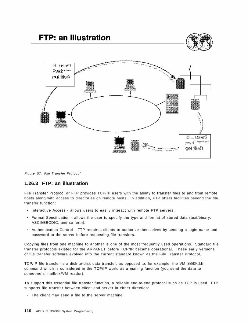
Figure 57. File Transfer Protocol
1.26.3 FTP: an illustration
File Transfer Protocol or FTP provides TCP/IP users with the ability to transfer files to and from remotehosts along with access to directories on remote hosts. In addition, FTP offers facilities beyond the filetransfer function:
• Interactive Access - allows users to easily interact with remote FTP servers.
• Format Specification - allows the user to specify the type and format of stored data (text/binary,ASCII/EBCDIC, and so forth).
• Authentication Control - FTP requires clients to authorize themselves by sending a login name andpassword to the server before requesting file transfers.
Copying files from one machine to another is one of the most frequently used operations. Standard filetransfer protocols existed for the ARPANET before TCP/IP became operational. These early versionsof file transfer software evolved into the current standard known as the File Transfer Protocol.
TCP/IP file transfer is a disk-to-disk data transfer, as opposed to, for example, the VM SENDFILEcommand which is considered in the TCP/IP world as a mailing function (you send the data tosomeone ′s mailbox/VM reader).
To support this essential file transfer function, a reliable end-to-end protocol such as TCP is used. FTPsupports file transfer between client and server in either direction:
• The client may send a file to the server machine.
110 ABCs of OS/390 System Programming

• The client may request a file from the server machine.
The user who initiates the FTP connection assumes the client function while the server function isperformed by the remote host.
FTP includes functions that allow authorized users to display, define, and delete files and directories,and to transfer files to and from remote TCP/IP hosts.
Most FTP server implementations allow concurrent access by multiple clients using TCP to connect tothe server. From an FTP user′s point of view, the link is connection-oriented. This means that it isnecessary to have both hosts up and running TCP/IP to establish a file transfer.
FTP uses two connections between the client and server system to perform the file transfer functions:
• The first one is for login from the client to the server and follows the TELNET protocol. Thisconnection is used for authentication of the client user, issuing commands to the FTP server, andso forth.
• The second one is for managing the data transfer. The actual file transfer occurs over thisconnection.
FTP can interface with RACF to provide access control.
Chapter 1. Network Management 111

Figure 58. X-Windows
1.26.4 X-Windows: an illustration
X-Windows is a windowing system that allows a user to simultaneously display bitmapped screensfrom several local and/or remote applications (processes).
Basically, there are two parts communicating with each other:
• The application (called the X-Client) which gets input from the user, executes code, and sendsoutput back to the user.
• The user′s terminal (called the X-Server) which runs display-managing software thatreceives/sends data from/to the application.
Note that in the previous application protocols we have discussed (TELNET, SMPT, and so forth) theuser is typically at the client end of the connection. With X-Windows, the user is at the server end ofthe connection. Each application that is displaying data in one of the windows is considered a client.
The X-Windows Application Programming Interface (API) (developed at MIT as part of the AthenaProject) allows a TCP/IP user to run applications on several systems through a single workstationimage. The X-Window system is one of the most widely used Graphical User Interface (GUI), orbitmapped-window display systems.
The user is able to control all sessions from one screen, with applications either running in a window,or in separate virtual terminals but with an icon on the primary screen reminding the user of theexistence of that application (similar to the OS/2 Presentation Manager).
112 ABCs of OS/390 System Programming

The X-Window system provides the capability of managing both local and remote windows:
• Remote windows are established through TCP/IP.
• Local windows are established through the use of BSD sockets.
This function is most useful for applications that require computing resources that are not available atthe user′s workstation. The X-Windows API allows a client program to access a bit-mapped,high-resolution display connected to a X-Windows system protocol server program.
Chapter 1. Network Management 113

Figure 59. REXEC support
1.26.5 REXEC support
The Remote Execution Command (REXEC) is used in conjunction with the Remote Execution CommandDaemon (REXECD). It allows a TCP/IP user to execute commands on a remote host and receive theresults on the local system.
• The client function is performed by the REXEC process.
• The server function is performed by the REXECD process.
REXECD is a server (also known as a daemon). It handles commands issued by remote hosts andtransfers orders to slave virtual machines for command execution. The daemon performs automaticlogin and user authentication when user ID and password are entered.
The REXEC command is used to define the user ID, password, host address, and process to be startedon the remote host. Both server and client are linked over the TCP/IP network.
114 ABCs of OS/390 System Programming

Figure 60. Network File System
1.26.6 Network File System
NFS was developed by SUN Microsystems. It allows host machines to share file systems across anetwork. NFS allows remote file systems to have the appearance of being local resources to users(protocol is transparent to the user).
The Network File System (NFS) provides on-line shared file access that is transparent and integrated.It allows TCP/IP sites to interconnect their computer file systems. From the user ′s perspective, NFS isalmost invisible. The user can execute an application program and use any file(s) (local and/orremote) for input or output. The file names do not show whether the files are local or remote.
When an application program executes, it calls the operating system to open a file, or to store andretrieve data in files. The file access mechanism accepts the request and automatically passes it toeither the local file system software or to the NFS client, depending on whether the file is on a localdisk or on a remote machine. When it receives a request, the NFS client software use the NFSprotocol to contact the appropriate server on a remote machine and perform the requested operation.When the remote server replies, the client software returns the results to the application program.
NFS was developed to be machine, operating system, and transport protocol independent; this wasaccomplished by using the RPC interface.
NFS implements two protocols: Mount protocol and NFS protocol:
• Mount protocol is used to establish the connection and access the appropriate set of files(directory).
Chapter 1. Network Management 115

The options supported include password security, code conversion, remote disk addresses, and soforth.
• NFS protocol is used for the actual disk functions.
Supported functions include searches, reading and writing, and directory maintenance.
Both Mount and NFS protocol are RPC applications (caller/server concept) and transported by UDP.
116 ABCs of OS/390 System Programming

Figure 61. TCP/IP data sets
1.27 TCP/IP data sets
Required for TCP/IP start-up and initialization are the procedure from SYS1.PROCLIB and theparameter data sets:
• TCP/IP start procedure
Copy the TCP/IP cataloged procedure in hlq.SEZAINST(TCPIPROC) to your system or recognizedPROCLIB and modify it to suit your local conditions. Specify TCP/IP parameters and remove orchange the DD statements as required. The jobname associated with the started task of theTCP/IP system address space must match the NAME parameter on the SUBFILESYSTYPEstatement in the BPXPRMxx member of ′SYS1.PARMLIB′ used to start OS/390 UNIX.
When TCP/IP is started via the S TCPIP command, it reads its configuration parameters from thedata set names specified on the PROFILE and SYSTCPD DD statements in the TCP/IP proc.
These data sets are generally referred to as: TCPDATA respectively.
• PROFILE parameter data set
• TCPDATA parameter data set
In the following example of a basic TCPIP procedure, note the PROFILE and SYSTCPD DD statementswhich specify the locations of TCP/IP′s parameter data sets.
Chapter 1. Network Management 117

� �//TCPIP PROC PARMS=′ CTRACE(CTIEZB00)′//*//* Communication Server/390//* SMP/E Distribution Name: EZAEB01G//*//TCPIP EXEC PGM=EZBTCPIP,// PARM=′&PARMS′ ,// REGION=7500K,TIME=1440//*//* SYSPRINT contains run-time diagnostics from TCPIP. It may be//* a data set or SYSOUT.//* ALGPRINT contains run-time diagnostics from TCPIP′ s Autolog//* task. It should be SYSOUT.//* SYSERROR contains error messages from TCPIP that occurred//* while processing the PROFILE.//*//SYSPRINT DD SYSOUT=*,DCB=(RECFM=VB,LRECL=132,BLKSIZE=136)//ALGPRINT DD SYSOUT=*,DCB=(RECFM=VB,LRECL=132,BLKSIZE=136)//SYSOUT DD SYSOUT=*,DCB=(RECFM=VB,LRECL=132,BLKSIZE=136)//SYSERROR DD SYSOUT=*//*//* TCPIP reads the parameters from a data set specified on//* the following PROFILE dd.//* See the chapter on ″Configuring the TCPIP Address Space″ in//* the Configuration Guide for more information.//* A sample of such a profile is included in member SAMOPROF in//* the SEZAINST data set.//*//PROFILE DD DISP=SHR,// DSN=SYS1.TCPIP.PARMS(PROFILE)//*//* SYSTCPD explicitly identifies which data set is to be//* used to obtain the parameters defined by TCPIP.DATA.//* The SYSTCPD DD statement should be placed in the TSO logon//* procedure or in the JCL of any client or server executed//* as a background task. The data set can be any sequential//* data set or a member of a partitioned data set (PDS).//*//* For more information please see ″Understanding TCP/IP Data//* Set Names″ in the Configuration Guide.//*//SYSTCPD DISP=SHR,// DSN=SYS1.TCPIP.PARMS(TCPDATA)� �
The names of the data sets or members containing TCP/IP code and parameters are specified in theTCP/IP start procedure, SYS1.PROCLIB(TCPIP).
These members can be located in any data set, but for the purposes of this overview we will assumethey are located in SYS1.TCPIP.PARMS.
118 ABCs of OS/390 System Programming

Figure 62. Configuring TCP/IP - Profi le data set
1.27.1 Configuring TCP/IP - Profile data set
A sample configuration data set is provided in hlq.SEZAINST(SAMPPROF). This member is used toconfigure the TCP/IP address space.
A typical TCP/IP Profile includes many configuration options and parameter values too numerous to listhere. However, for basic configuration purposes use the defaults in the supplied samples but payparticular attention to the following sections:
• IP address
The IP addresses of the host on each link. For example, your CPU may be communicating withyour TCP/IP network via two ports on an OSA card. Each port would have its own associated linkID and IP address. This example is defining the IP address 9.12.14.187 on Link OSAL2160 (definedby the DEVICE and LINK statements. The DEVICE and LINK parameters are used to define the type ofthe physical link the CPU is using to communicate with the TCP/IP network.
There are a number of possible matching DEVICE and LINK parameter values depending on thehardware in use. Refer to OS/390 V2R7.0 eNetwork CS IP Configuration, SC31-8513, for a completelist of possible values and their meanings.
Chapter 1. Network Management 119

� �; Hardware definitions:;; DEVICE OSA2160 LCS 2160LINK OSAL2160 IBMTR 0 OSA2160;HOME 9.12.14.187 OSAL2160� �
• Default router and subnet masks
It is best to either acquire a comprehensive understanding of IP addressing and subnet masking orobtain the help of a competent network specialist before tailoring this section of the TCP/IP Profiledata set.
� �;GATEWAY;; Direct Routes - Routes that are directly connected to my interfaces.;; Network First Hop Link Name Packet Size Subnet Mask Subnet Value9 = OSAL2160 4096 0.255.255.0 0.12.2.0
;; Indirect Routes - Routes that are reachable through routers on my; network.;; Network First Hop Link Name Packet Size Subnet Mask Subnet Value; 193.12.2 130.50.10.1 TR1 2000 0; 10.5.6.4 193.5.2.10 ETH1 1500 HOST;;; Default Route - All packets to an unknown destination are routed; through this route.;; Network First Hop Link Name Packet Size Subnet Mask Subnet ValueDEFAULTNET 9.12.2.75 OSAL2160 4096 0
;� �• Start devices
Lastly, enter the names of the LINKs that TCP/IP will start automatically during initialization.
� �; Start all defined DEVICEs;START OSA2160� �
*
120 ABCs of OS/390 System Programming

Figure 63. Configuring TCP/IP - TCPDATA
1.27.2 Configuring TCP/IP - TCPDATA
As with the TCP/IP Profile, TCPDATA contains many parameters that you should not change until youhave developed a good understanding of TCP/IP and are in a position to know what you are doing.
It is advisable to accept most of the values in the sample member, but pay particular attention to thefollowing sections:
• Host name
For YOURMVSNAME, WTSC47 in this example, specify your OS/390 system name. This should be thesame as your JES nodename. The colon after it is required. The word HOSTNAME should be enteredfollowed by what you want to call your TCP/IP host. It is recommended you have both names thesame, as in the example, to avoid confusion. Case translation is not performed on the host name.
� �; HOSTNAME specifies the TCP host name of this system. If not; specified, the default HOSTNAME will be the node name specified; in the IEFSSNxx PARMLIB member.;; YOURMVSNAME: HOSTNAME YOURTCPNAMEWTSC47: HOSTNAME WTSC47� �
Chapter 1. Network Management 121

• Domain name
The TCP/IP domain suffix that will be appended to the hostname. In this example, our hostname isWTSC47. The suffix ITSO.IBM.COM will be appended to WTSC47, giving a fully qualified domain name ofWTSC47.ITSO.IBM.COM.
� �; DOMAINORIGIN specifies the domain origin that will be appended; to host names passed to the resolver. If a host name contains; any dots, then the DOMAINORIGIN will not be appended to the; host name.;DOMAINORIGIN ITSO.IBM.COM� �
• Nameserver IP address
Specify the IP address of your name server. If you are unsure of the correct value, speak to yournetwork specialist. If you are not using a name server and this host will be resolving all domainnames for itself, the NSINTERADDR statement(s) can be commented out.
� �; NSINTERADDR specifies the IP address of the name server.; LOOPBACK (14.0.0.0) specifies your local name server. If a name; server will not be used, then do not code an NSINTERADDR statement.; (Comment out the NSINTERADDR line below). This will cause all names; to be resolved via site table lookup.;NSINTERADDR 9.12.14.204NSINTERADDR 9.12.14.7� �
122 ABCs of OS/390 System Programming

Figure 64. Customizing TCP/IP
1.27.3 Customizing TCP/IP
Steps for customizing TCP/IP are as follows:
• Choose a High-Level Qualifier (hlq).
TCP/IP uses dynamic allocation with this hlq to get parameters from several TCP/IP data sets. TheDATASETPREFIX statement in TCPIP.DATA can be used to override the default hlq. However, it isused as the last step in the search order for most configuration files.
• Update the following PARMLIB members:
IEAAPFxx/PROGxx Authorizes the following libraries:
• hlq.SEZATCP• hlq.SEZADSIL• hlq.SEZALINK• hlq.SEZALNK2• hlq.SEZALPA• hlq.SEZAMIG
LNKLSTxx hlq.SEZALINK
LPALSTxx hlq.SEZALPA and hlq.SEZATCP
IECIOSxx Use to disable the MIH processing for the communication device used byTCP/IP
Set MIH TIME=00:00,DEV=(cuu-cuu)
Chapter 1. Network Management 123

IEFSSNxx Define subsystems to use restartable VMCF and TNF
• SUBSYS SUBNAME(TNF)• SUBSYS SUBNAME(VMCF)
SCHEDxx Set PPT entries
• PPT PGMNAME(MVPTNF) KEY(0) NOCANCEL NOSWAP PRIV SYST• PPT PGMNAME(MVPXVMCF) KEY(0) NOCANCEL NOSWAP PRIV SYST• PPT PGMNAME(EZBTCPIP) KEY(6) NOCANCEL NOSWAP PRIV SYST
Note: The default program properties table (PPT) shipped with the OS/390 V2R7 base control program(BCP) includes entries for Communication Server (CS) for OS/390. Therefore, the SCHEDxx entriespreviously required are no longer required. If you have those entries in your own parmlib, removethem. If you used the IBM copy of parmlib, they have been removed for you. For details, refer to theOS/390 MVS Initialization and Tuning Reference, SC28-1752.
124 ABCs of OS/390 System Programming

Figure 65. Customizing TCP/IP
1.27.4 Customizing TCP/IP
Update the following PARMLIB members:
COMMNDxx Add the following command to start the SSI:
COM=′ S EZAZSSI,P=sys_name′
Where sys_name is the SYSNAME in IEASYSxx or specified in IEASYMxx using theSYSDEF statement.
IFAPRDxx Enable TCP/IP base by adding this:
NAME(OS/390) ID(5647-A01)
BPXPRMxx Activate TCP/IP support for transport provider as follows:
FILESYTYPE TYPE(INET) ENTRYPOINT(EZBPFINI)NETWORK DOMAINNAME(AF_INET)
DOMAINNUMBER(2)MAXSOCKETSR(10000)TYPE(INET)
Chapter 1. Network Management 125

Figure 66. Routing
1.27.5 Routing
To support IP dynamics, NCP′s Network Definition Facility (NDF) builds a routing information table (RIT)for networks and subnetworks for use by TCP/IP at NCP generation time.
The RIT consists of routing tables that are generated from the NCP IPROUTE and IPLOCAL statements.During NCP generation, the RIT is added as a member of the NCP load library partitioned data setncp.v7r1.ncpload. You identify the member name of ncp.v7r5.ncpload that NCPROUTE uses atexecution time with the NEWNAME parameter of the BUILD statement for each NCP client generation.
Each entry in the routing table is created, for static routing, from the definitions in the TCP/IP Profiledata set:
� �;; Network First Hop Link Name Packet Size Subnet Mask Subnet Value193.12.2 130.50.10.1 TR1 2000 010.5.6.4 193.5.2.10 ETH1 1500 HOST
;� �
126 ABCs of OS/390 System Programming

Figure 67. Routing
1.27.6 Routing
The following types of routing are defined in the TCP/IP Profile data set:
Direct Direct routing can take place when two hosts are directly connected to the same physicalnetwork. This can be a bridged token-ring network, a bridge Ethernet, or a bridgedtoken-ring network and Ethernet. The distinction between direct routing and indirect routingis that with direct routing IP datagram can be delivered to the remote host withoutsubsequent interpretation of the IP address, by an intermediate host or router.
Indirect Indirect routing takes place when the destination is not on a directly-attached IP network,forcing the sender to forward the datagram to a router for delivery.
Default A default route is typically used on a gateway or router to an internet, or on a gateway orrouter that uses another routing protocol, whose routes are not reported to other localgateways or routers.
To configure a route to a default destination, add a default route using the passive routedefinition in the gateways file or data set. For example, if the default destination router hasa gateway address 9.12.112.1, then add the following entry to the data set:
net 0.0.0.0 gateway 9.12.112.1 metric 1 passive
Only one default route to a destination gateway or router can be specified. OROUTEDcurrently does not support multiple default routes.
IPROUTE DESTADDR=0.0.0.0,NEXTADDR=9.12.112.1,INTFACE=TR88,METRIC=1,DISP=PERM
Chapter 1. Network Management 127

Figure 68. TCP/IP applications
1.28 TCP/IP applications
TN3720 TELNET is most often used as the primary method of connection between clientworkstations and the SNA mainframe environment. TELNET terminal emulation needs tosimulate actual SNA terminals as closely as possible to make this form of remoteconnection as seamless as possible to end users. RFC1647, also known as TN3270E,adds the ability to simulate specific terminal LU connection and support printer devicesand additional SNA functions.
FTP File Transfer Protocol (FTP) lets you transfer data sets between the local host and anyother host that supports TCP/IP. Using the FTP command and its subcommands, you cansequentially access multiple hosts without leaving the FTP environment.
telnet The telnet support comes with the TCP/IP OS/390 UNIX feature. It also uses the inetddaemon which must be active and set up to recognize and receive the incoming telnetrequests.
OS/390 UNIX telnet code is installed in the hierarchical file system (HFS) (path/usr/lpp/tcpip/sbin/otelnetd with a symbolic link to /usr/sbin/otelnetd) and in the MVS dataset hlq.SEZALINK. The hlq.SEZALINK data set needs to be a PADS protected data set ifyou are running with the BPX.DAEMON facility class defined. OS/390 UNIX checkswhether the sticky bit is set on in the HFS. If it finds the sticky bit on, it first checks for anexecutable file in the MVS data set. If it does not find the executable file in a data set inthe MVS search order, OS/390 UNIX then uses the executable file in the HFS.
128 ABCs of OS/390 System Programming

rlogin When the inetd daemon is set up and active, you can rlogin to the shell from aworkstation that has rlogin client support and is connected via TCP/IP or CommunicationsServer to the MVS system. To login, use the rlogin (remote log in) command syntaxsupported at your site.
The inetd daemon provides service management for a network. For example it starts therlogind program whenever there is a remote login request from a workstation.
The rlogind program is the server for the remote login command rlogin, commonly foundon UNIX systems. It validates the remote login request and verifies the password of thetarget user. It starts an OS/390 shell for the user and handles translation between ASCIIand EBCDIC code pages as data flows between the workstation and the shell.
When inetd is running and receives a request for a connection, it processes that requestfor the program associated for that socket. For example, if a user tries to log in from aremote system into the OS/390 shell while inetd is running, inetd processes the requestfor connection and then issues a fork() and execl() to the rlogin program to process therlogin request.
It then goes back to monitoring for further requests for those applications that can befound as defined in the /etc/inetd.conf file.
Chapter 1. Network Management 129

Figure 69. TN3270 parms
1.28.1 TN3270 parms
The TELNET server gets some of its configuration parameters through the TELNETPARMS statements.If you want to specify parameters for the TELNET server, update the TELNETPARMS section of theTCP/IP Profile data set.
� �;; TELNET parmsTELNETPARMSPORT 623WLMCLUSTERNAME TN3270E ENDWLMCLUSTERNAME
ENDTELNETPARMS;� �
The TELNETDEVICE statement lets you specify a logmode for a device type anywhere within theBEGINVTAM/ENDVTAM block, instead of just at the beginning of the block (as with the BEGINVTAMstatement). This statement accepts two logmodes: one for 3270 connections and one for 3270Econnections.
130 ABCs of OS/390 System Programming

Figure 70. FTP
1.28.2 FTPFile Transfer Protocol (FTP) is the simplest way to transfer files between computers connected by aTCP/IP network. The direction of the file transfer can be either PUSH (send a file to the remote host)or PULL (get a file from the remote host). The local and remote hardware and software are largelyirrelevant, and you can select to transfer files in ASCII, BINARY, or EBCDIC format from any machineto any other machine.
For example, a flat text file can be transferred in ASCII format from a PC workstation to VM/ESA, orOS/390, or UNIX and its contents will still be readable as a flat text file when it arrives at itsdestination. A compressed (zipped) PC file can be transferred in binary format to an OS/390 machinefor storage and then transferred from there to a different PC where it will arrive intact and can besuccessfully decompressed (or unzipped).
FTP is a client-server protocol where the initiating side of the connection is the FTP client and theclient connects to an FTP server.
FTP provides various commands to connect to a remote host, change the active directory, define thedata transfer format, and obviously, send and receive files. A few of the more useful ones are:
AScii Set transfer mode to text
Binary Set transfer mode to binary
CD Change active Directory on remote side
CLose Close connection
Chapter 1. Network Management 131

DIR Get directory listing of remote files
Get Retrieve files from remote host
MGet Multiple Get for multiple files (for example, R*.DAT)
MPut Multiple Put for multiple files
Open Initiate connection to remote site
PASS Send password to remote host (if remote host requires a password)
Put Send file to remote host
PWD Query Preset Working Directory on remote host
QUIT Close connection to remote host, or EXIT ftp if no connection active
SYStem Query the remote operating system type
USer Initiate a logon to remote host once connection is established
For a complete list of available FTP commands and their usage and syntax refer to eNetworkCommunications Server: IP User′s Guide, GC31-8514.
132 ABCs of OS/390 System Programming
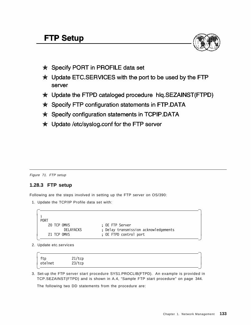
Figure 71. FTP setup
1.28.3 FTP setup
Following are the steps involved in setting up the FTP server on OS/390:
1. Update the TCP/IP Profile data set with:
� �;PORT
20 TCP OMVS ; OE FTP ServerDELAYACKS ; Delay transmission acknowledgements
21 TCP OMVS ; OE FTPD control port� � 2. Update etc.services
� �ftp 21/tcpotelnet 23/tcp� �
3. Set-up the FTP server start procedure SYS1.PROCLIB(FTPD). An example is provided inTCP.SEZAINST(FTPD) and is shown in A.4, “Sample FTP start procedure” on page 344.
The following two DD statements from the procedure are:
Chapter 1. Network Management 133

� �//SYSFTPD DD DISP=SHR,DSN=SYS1.TCPIP.PARMS(FTPDATA) �1�//SYSTCPD DD DISP=SHR,DSN=SYS1.TCPIP.PARMS(TCPDATA) �2�� �
Point the SYSTCPD DD (�2�) at the TCPDATA file (see 1.27, “TCP/IP data sets” on page 117).
4. Customize FTPDATA (�1�).
A sample FTPDATA is provided in TCPIP.SEZAINST(FTPSDATA). Copy this member toSYS1.TCPIP.PARMS(FTPDATA).
5. Add FTPD to the AUTOLOG section in the TCP/IP Profile (see the AUTOLOG section under 1.27.1,“Configuring TCP/IP - Profile data set” on page 119).
1.28.3.1 FTP usage
In the following FTP example, the file EXLOCAL VTAMLST is being retrieved from a remote VM/ESA systemand stored in the member DAVIETN.STUFF(EXLOCAL). The local OS/390 system in this example is theclient side of the connection and the remote VM/ESA system is the server.
134 ABCs of OS/390 System Programming
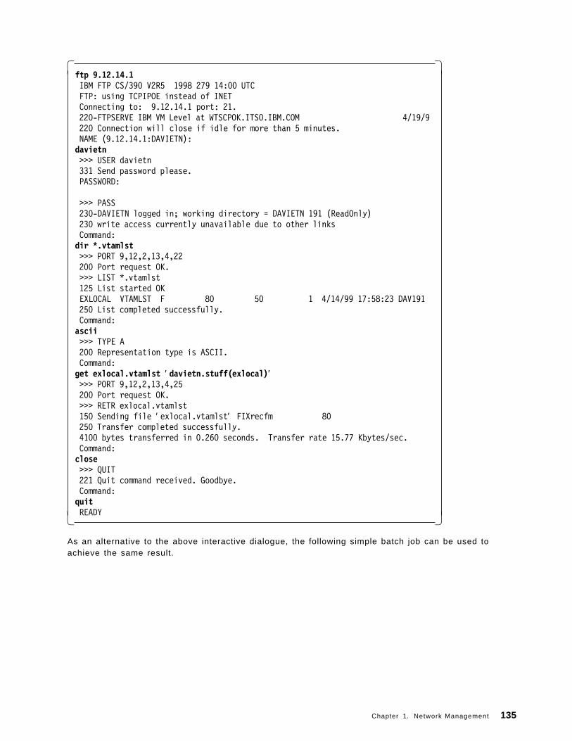
� �ftp 9.12.14.1 IBM FTP CS/390 V2R5 1998 279 14:00 UTC FTP: using TCPIPOE instead of INET Connecting to: 9.12.14.1 port: 21. 220-FTPSERVE IBM VM Level at WTSCPOK.ITSO.IBM.COM 4/19/9 220 Connection will close if idle for more than 5 minutes. NAME (9.12.14.1:DAVIETN):davietn >>> USER davietn 331 Send password please. PASSWORD:
>>> PASS 230-DAVIETN logged in; working directory = DAVIETN 191 (ReadOnly) 230 write access currently unavailable due to other links Command:dir *.vtamlst >>> PORT 9,12,2,13,4,22 200 Port request OK. >>> LIST *.vtamlst 125 List started OKEXLOCAL VTAMLST F 80 50 1 4/14/99 17:58:23 DAV191 250 List completed successfully. Command:ascii >>> TYPE A 200 Representation type is ASCII. Command:get exlocal.vtamlst ′ davietn.stuff(exlocal)′ >>> PORT 9,12,2,13,4,25 200 Port request OK. >>> RETR exlocal.vtamlst 150 Sending file ′ exlocal.vtamlst′ FIXrecfm 80 250 Transfer completed successfully. 4100 bytes transferred in 0.260 seconds. Transfer rate 15.77 Kbytes/sec. Command:close >>> QUIT 221 Quit command received. Goodbye. Command:quit READY� �
As an alternative to the above interactive dialogue, the following simple batch job can be used toachieve the same result.
Chapter 1. Network Management 135

� �//USERIDX JOB USERID,MSGLEVEL=(1,1),NOTIFY=USERID,MSGCLASS=H//FTP EXEC PGM=FTP,REGION=4096K//INPUT DD *9.12.14.1davietnpasswordtype Aget exlocal.vtamlst ′ davietn.stuff(exlocal)′quit/*//OUTPUT DD SYSOUT=*//SYSPRINT DD SYSOUT=*� �
136 ABCs of OS/390 System Programming

Figure 72. FTP daemon
1.28.4 FTP daemon
File Transfer Protocol (FTP) is used to transfer files between TCP/IP hosts. The FTP client is theTCP/IP host that initiates the FTP session, while the FTP server is the TCP/IP host to which the clientconnects.
The FTP server uses two different ports and manages two TCP connections:
• Port 21 is used to control the connection (user ID and password).• Port 20 is used for actual data transfer based on the FTP client′s requests.
The FTP server in OS/390 IP consists of the daemon (the listener) or ftpd and server address space (orprocesses). The daemon performs initialization, listens for new connections, and starts a separateserver address space for each connection.
When a new client FTP connects to the FTPD daemon process, ftpd forks an FTP server process; thus,a new jobname is generated by OS/390 UNIX System Services.
The OS/390 eNetwork Communication Server IP FTP server and client exploit OS/390 UNIX SystemServices and provide access to both traditional MVS data sets and OS/390 UNIX hierarchical filesystem files.
The FTP server does not use inetd as a listener process, but has its own listener program, which is theFTP daemon address space.
Chapter 1. Network Management 137

When a client connects, the daemon forks a new address space to handle that client session.
To start the FTP daemon, you can use /etc/rc as shown on the next visual, or you can use thePROFILE.TCPIP data set.
Additional Information can be found in the following publications:
OS/390 UNIX System Services Planning, SC28-1890
OS/390 eNetwork Communication Server IP Configuration, SC31-8513
OS/390 TCP/IP OpenEdition Implementation Guide, SG24-2141
OS/390 eNetwork Communication Server TCP/IP Implementation Guide Volume 2, SG24-5228
138 ABCs of OS/390 System Programming

Figure 73. Logging in to OS/390 UNIX shell
1.28.5 Logging in to OS/390 UNIX shell
Typically, a user does not want to log in through an intermediate TSO stage, but would rather usestandard UNIX techniques to log in directly to a shell ID in OS/390 UNIX.
The visual shows the many different ways available to start an OS/390 UNIX shell session. Let usreview the different mechanisms to start an OS/390 UNIX shell session.
• Started via the TSO OMVS command:
− A TSO user, logged in via SNA and VTAM, can issue the OMVS commands directly from theTSO command line.
− A workstation user can use TCP/IP TN3270 protocol to logon to a TSO user ID via IP 3270(E)TELNET server. From TSO, use OMVS to access the shell.
• Started via rlogin done directly from workstation:
− An UNIX/AIX user can use a standard “rlogin” client to do remote login to OS/390 UNIX. AnOS/390 UNIX rlogin daemon initiates the shell.
• Started via telnet done directly from workstation:
− Any platform can use a standard “telnet” client to do remote login to OS/390 UNIX. An OS/390UNIX telnet daemon initiates the shell.
• Started via Communication Server (CS) LOGIN request:
Chapter 1. Network Management 139

− An ASCII terminal directly attached to an OCS RS/6000 host can use local login to OS/390 UNIXto access the OS/390 UNIX shell.
− A networked user attached to an RS/6000 CS host can route “rlogin” or “telnet” requests forOS/390 UNIX through a CS client on AIX. The CS login monitor (lm) server on OS/390 UNIXestablishes shell sessions on behalf of these clients.
• Both direct “rlogin/telnet” and CS assisted logins support “raw” mode.
140 ABCs of OS/390 System Programming

Figure 74. Using inetd - master of daemons
1.28.6 Using inetd - master of daemons
The inetd daemon, usually known as inetd or InetD, is a master of other daemons that execute inOS/390 UNIX. The function of inetd is to listen on certain “well-known” network ports for a request torun one of a number of daemons. When a request is received, inetd creates a new socket for remoteconnection, and then fork()s a new address space and uses exec() to start the requested daemonprogram.
The daemon started by inetd relates to the port where the request arrived. The correlation betweenport number and daemon is stored in configuration file /etc/inetd.conf.
The daemons started by inetd include:
• The rlogin daemon starts a shell session for a user rlogin request.• The TELNET daemon starts a shell session for a user TELNET request.• The rexec daemon executes a single command on OS/390 UNIX requested by a remote user
entering an rexec command.• The rsh daemon starts a shell session and runs a script generated by a remote user entering an
rsh command.
Customization is needed to enable inetd to run on your system. You must decide how to start it, andwhat RACF ID it will execute under. If you have implemented enhanced daemon security withBPX.DAEMON, you must define inetd to the BPX.DAEMON and implement program control. Finally,you have to configure the relationship between the ports that inetd listens on and the daemons to bestarted.
Chapter 1. Network Management 141

Figure 75. Customize inetd (part 1)
1.28.7 Customize inetd (part 1)
This visual and the next visual describe the steps necessary to customize the inetd daemon.
1. The inetd daemon program can be found in two places. In the HFS, the program file is/usr/sbin/inetd, but IBM has set the sticky bit on. A copy of this program is found in′SYS1.LINKLIB(INETD)′, so this is the program that is used. You can use any of the methods tostart a daemon, but the approved production ways are:
• Start it from an OS/390 procedure like the one shown. The jobname comes from the label onproc = INETD. Parms supply the two variable values:
− Program module name
− Parameter passed to INETD program = name of inetd configuration file
• Start from a line in the initialization script /etc/rc. In this case, use a command similar to theline shown.
2. The next step is to decide which user ID to associate with inetd. It needs to be a superuser(UID=0), and have minimum access to MVS data sets. How you do this depends on the startmode:
• If started from /etc/rc, inetd inherits user ID OMVSKERN, which is superuser.
• If started via STC, you need to associate the RACF UID with the STC name by updating theRACF STARTED facility class. You could use the kernel ID OMVSKERN, or you can create anew superuser ID and then use that one.
142 ABCs of OS/390 System Programming

3. If you have activated the RACF BPX.DAEMON facility, then the INETD user ID must be authorized tothis facility.
Chapter 1. Network Management 143

Figure 76. Customize inetd (part 2)
1.28.8 Customize inetd (part 2) 1. If you have set up the BPX.DAEMON, then you need to make sure that all programs are loaded into
the inetd address space. At a minimum, you should protect the following programs:
• SYS1.LINKLIB(INETD).• CEE.SCEERUN - LE/MVS run time - whole library
2. There are three configuration files that have to be updated for inetd support:
• The primary file is /etc/inetd.conf, which is the inetd configuration file. There is one entry (line)in this file for each daemon controlled by inetd. The fields are interpreted as follows:
− Field (1) - Service name - match daemon entry in /etc/services file− Field (2) - Daemon socket type - stream or dgram− Field (3) - Daemon socket protocol - TCP or UDP− Field (4) - Wait_flag - can be wait (single thread server - one request at a time) or nowait
(multiple requests queued)− Field (5) - Login_name - RACF user ID under which daemon will run− Field (6) - Server_program - name of daemon program in HFS− Field (7) - Server-arguments - first string is jobname for daemon address space, and the
rest is the parm string to pass to daemon
• There is a corresponding entry in /etc/services for each daemon in inetd.conf. The entry liststhe port where inetd listens for daemon requests.
144 ABCs of OS/390 System Programming

• The TCP/IP Profile configuration must list the same ports in the PORT section. This entryidentifies the job name authorized to open the socket to this port and the type of socketallowed.
• The two TCP/IP files usually exist already—you must make sure that inetd.conf correspondswith the values listed. You may want to change the port number for a daemon.
3. After all configuration is complete, start inted.
Chapter 1. Network Management 145

Figure 77. Start options for daemons
1.28.9 Start options for daemons
In an OS/390 system, there are several ways of starting and restarting daemons. The method useddepends on the level of control the installation has chosen for daemons. The daemon programs areinstalled in /usr/sbin with the sticky bit on and in SYS1.LINKLIB. Daemons can be started using thefollowing methods:
• As a cataloged procedure (started task). Create a cataloged procedure. In order for the procedureto get control with the correct authority, an entry must be added to the RACF started procedurestable (ICHRIN03) or a profile added to the STARTED class. The daemons need superuser authority.Start the daemon by using the operator command S daemon_proc_name (for example, ′S INETD′).
• To be started automatically when the kernel is started, place the start options in the HFS file called/etc/rc. The initialization of OS/390 UNIX includes running the commands in /etc/rc. The_BPX_JOBNAME environment variable assigns a job name to the daemon.
• As a cataloged procedure using the BPXBATCH program to invoke the daemon program.
If daemons need to be stopped, the kill command is typically used. Some daemons may have theirown specific method of shutdown.
You should have appropriate procedures and directions in place to restart these daemons in case offailure. Started procedures are one way to do this, which may be more attractive depending on yourautomation strategy.
146 ABCs of OS/390 System Programming

In an OS/390 system, most started tasks which are continuously executing are started from a catalogedprocedure, for example located in SYS1.PROCLIB. The visual shows an example with a proc calledINETD in SYS1.PROCLIB. It will execute the program INETD from SYS1.LINKLIB. To associate theINETD procedure with the correct user ID, an entry must be created in the RACF started procedurestable (ICHRIN03) or a profile added to the STARTED class. This is done in the same way as we did forthe OMVS procedure. The HFS file /etc/inetd.conf is a configuration file for the inetd daemon. Itcontains start options for the daemons controlled by inetd.
Chapter 1. Network Management 147

Figure 78. Define daemon security
1.28.10 Define daemon security
In many cases a daemon program is started from the kernel and will inherit the kernel user ID,OMVSKERN. This example shows that it can have a separate user ID as long as the user ID is definedas a superuser. This superuser must be defined with a UID=0 in RACF, which means that this usercannot become a superuser by using the su command.
Note: This user ID should not have a TSO/E segment defined; only the OMVS segment is needed.
The following steps describe how to define security for a daemon:
1. Define a user ID for the daemon which is a superuser with UID=0, for example OMVSCRON:
ADDUSER OMVSCRON DFLTGRP(OMVSGRP) OMVS(UID(0) HOME(′ / ′ ) PROGRAM(′ / bin/sh
2. Define the BPX.DAEMON FACILITY class in RACF:
RDEFINE FACILITY BPX.DAEMON UACC(NONE)
The name BPX.DAEMON must be used. No substitutions for this name are allowed. UACC(NONE)is recommended.
If this is the first RACF FACILITY class defined in RACF, the SETROPTS command must be used toactivate the class.
SETROPTS CLASSACT(FACILITY) GENERIC(FACILITY) AUDIT(FACILITY)SETROPTS RACLIST(FACILITY)
3. Permit the daemon user ID to the BPX.DAEMON class:
148 ABCs of OS/390 System Programming

PERMIT BPX.DAEMON CLASS(FACILITY) ID(OMVSCRON) ACCESS(READ)
4. Activate RACF program control:
SETROPTS WHEN(PROGRAM)
You can choose to protect a whole program library or individual load modules (members) in alibrary. The daemon program must reside in a program-controlled MVS partitioned data set, or inan HFS file with the extended attribute turned on via the extattr +p command. Both the programlibrary for the daemons (for example, SYS1.LINKLIB) and the C runtime library must be protected.
5. Protect the program libraries that need to be protected from unauthorized updates:
ADDSD ′ SYS1.LINKLIB′ UACC(READ)ADDSD ′ SYS1.SCEERUN′ UACC(READ)ADDSD ′ SYS1.SEZALINK′ UACC(READ)ADDSD ′ SYS1.SEZATCP′ UACC(READ)ADDSD ′ SYS1.SIMWMOD1′ UACC(READ)
The ADDSD command creates data set profiles for the data sets. You should protect againstunauthorized updates so that nobody can replace a daemon program with a fake daemon program.If these profiles are already defined, this step can be skipped.
The installation has a choice of either protecting all programs in a program library or individualprograms. To protect all members in a data set, specify PROGRAM *.
Note: Libraries in the LNKLIST concatenation are opened during IPL, and the programs in themare available to anyone unless the program name is defined as a controlled program. Mark thedata sets as controlled libraries:
RDEFINE PROGRAM * ADDMEM(′ SYS1.LINKLIB′ / / NOPADCHK +′ SYS1.SCEERUN′ / / NOPADCHK +′ SYS1.SEZALINK′ / / NOPADCHK +′ SYS1.SEZATCP′ / / NOPADCHK +′ SYS1.SIMWMOD1′ / / NOPADCHK) UACC(READ)
Or, mark the daemon program as controlled instead of the whole library:
RDEFINE PROGRAM CRON ADDMEM(′ SYS1.LINKLIB′ / / NOPADCHK)UACC(READ) AUDIT(ALL)
Place the PROGRAM profile in storage:
SETROPTS WHEN(PROGRAM) REFRESH
Chapter 1. Network Management 149

1.29 OSA/SFOpen Systems Adapter/Support Facility (OSA/SF) is comprised of a suite of programs and utilities thatare used to re-configure an Open Systems Adapter (OSA). The modes of OSA operation include:
• TCP/IP Passthrough
Providing communications between the server TCP/IP applications and TCP/IP clients on the LAN
• SNA
Systems Network Architecture
• HPDT ATM Native
High Performance Data Transfer Asynchronous Transfer Mode
• ATM IP Forwarding
• HPDT MPC
High Performance Data Transfer Multi-Path Channel
• LANRES/MVS
LAN Resource Extension and Services/MVS
The OSA-2 can be configured to allow sharing among logical partitions (LPAR support) using OSA/SF.When the S/390 server is running in LPAR mode, TCP/IP and SNA/APPN applications can share accessto an OSA-2 and can access the same LAN port. This is accomplished by configuring the OSA AddressTable (OAT), and loading it onto the OSA. The OAT is used to define the possible modes of datatransfer through the OSA. Each OSA has its own OAT, and the OAT is stored in the OSA innon-volatile storage, meaning that it can survive power outages and system reloads.
The OSA/SF utilities are shipped with OS/390 both as a downloadable GUI and as TSO REXX EXECs.
OSA/SF and OSA configuration is described in detail in OS/390 V2R7.0 OSA/SF User′s Guide,SC28-1855.
150 ABCs of OS/390 System Programming

Figure 79. OSA/SF configuration
1.30 OSA/SF configuration
The most widely used type of OSA card is the ENTR that supports both TCP/IP and SNA traffic and canconnect to both token-ring and Ethernet LANs.
The default mode of operation for an ENTR is TCP/IP Passthrough. The OSA card is capable ofsensing whether it is connected to an Ethernet or a token-ring LAN and will therefore be ready tocommunicate using TCP/IP in a limited fashion without further modification.
The OSA is configured by using the supplied OSA/SF utilities. Re-configuration is performed bydownloading a copy of the currently active OAT, modifying it, and reloading it to the OSA.
An example of a complete OAT is included in Appendix A.5, “Sample OAT” on page 345.Customization and setup of an OAT is described in 1.30.5, “OSA Address Table” on page 161.
Chapter 1. Network Management 151

Figure 80. OSA/SF definitions
1.30.1 OSA/SF definitions
The OSA card must be defined to the CPU via IOCP definition statements.
CHPID The CHPID statement defines the OSA Channel Path ID (CHPID) as type OSA. Type OSAis a special kind of internal channel type used only for OSAs:
� �CHPID PATH=(5C),TYPE=OSA� �
This example defines the OSA on channel 5C.
CNTLUNIT The CNTLUNIT statement defines a control unit for the OSA:
� �CNTLUNIT CUNUMBR=0D00,PATH=(1C),UNIT=OSA� �
IODEVICE The IODEVICE statements are as follows:
� ��1�IODEVICE CUNUMBR=D00,UNIT=OSA,ADDRESS=(D00,14), x
STADET=Y,UNITADD=00�2�IODEVICE CUNUMBR=D00,UNIT=OSAD,ADDRESS=(D0F), x
STADET=Y,UNITADD=FE� �Note: There are two separate IODEVICE statements.
152 ABCs of OS/390 System Programming
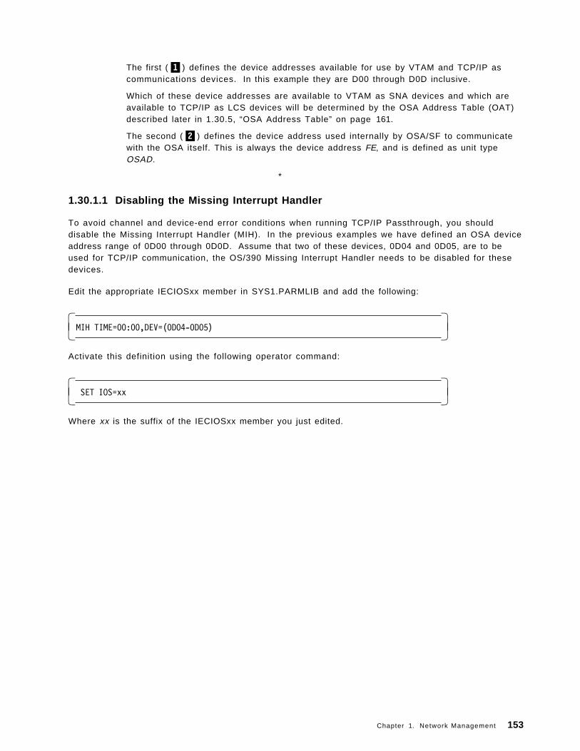
The first (�1�) defines the device addresses available for use by VTAM and TCP/IP ascommunications devices. In this example they are D00 through D0D inclusive.
Which of these device addresses are available to VTAM as SNA devices and which areavailable to TCP/IP as LCS devices will be determined by the OSA Address Table (OAT)described later in 1.30.5, “OSA Address Table” on page 161.
The second (�2�) defines the device address used internally by OSA/SF to communicatewith the OSA itself. This is always the device address FE, and is defined as unit typeOSAD.
*
1.30.1.1 Disabling the Missing Interrupt Handler
To avoid channel and device-end error conditions when running TCP/IP Passthrough, you shoulddisable the Missing Interrupt Handler (MIH). In the previous examples we have defined an OSA deviceaddress range of 0D00 through 0D0D. Assume that two of these devices, 0D04 and 0D05, are to beused for TCP/IP communication, the OS/390 Missing Interrupt Handler needs to be disabled for thesedevices.
Edit the appropriate IECIOSxx member in SYS1.PARMLIB and add the following:
� �MIH TIME=00:00,DEV=(0D04-0D05)� �
Activate this definition using the following operator command:
� � SET IOS=xx� �
Where xx is the suffix of the IECIOSxx member you just edited.
Chapter 1. Network Management 153

Figure 81. Setting up OSA/SF
1.30.2 Setting up OSA/SF
Detailed instructions on setting up OSA/SF can be found in OS/390 Open Systems Adapter SupportFacility User′s Guide, SC28-1855.
The following steps are a brief summary of the necessary actions required to set up OSA/SF.
1.30.2.1 Set up OSA/SF start procedure
The following is an example of a SYS1.PROCLIB(OSASF) startup procedure.
� �//*//* START OSA SUPPORT FACILITY//*//OSASF EXEC PGM=IOAMAIN,TIME=1440,REGION=4M,DYNAMNBR=5//IOALIB DD DSN=SYS1.SIOALMOD,DISP=SHR//IOAPROF DD DSN=SYS1.OSASF.PROFILE,DISP=SHR//SYSPRINT DD SYSOUT=*,DCB=(RECFM=FBA,LRECL=121,BLKSIZE=121)//SYSUDUMP DD SYSOUT=*� �
Note the IOALIB DD which points to the OSA/SF load library and the IOAPROF DD which points to theOSA/SF profile.
154 ABCs of OS/390 System Programming

1.30.2.2 OSA/SF profile data set
The startup profile defines the data set names of the OSA/SF configuration and master index data setas well as the high level qualifier (HLQ) of the OSA/SF working data sets.
� �SET ALIAS SYSNAME SC50SET ALIAS CECNAME SCZP401*SET NAME IOACFG
Data set ′ OSASF.&CECNAME.OSAS.CONFIG′UNIT SYSALLDA
*SET NAME IOAINX
Data set ′ OSASF.&CECNAME.MASTER.INDEX′UNIT SYSALLDA
*SET NAME IOAMSG
Data set ′ OSASF.SC68MESSAGE.LOG′UNIT SYSALLDA
*SET NAME IOADSN
Data set ′ OSASF.&CECNAME.OSASF′UNIT SYSALLDA� �
A sample member is included in IOA.SIOASAMP(IOASPROF) and can be tailored as shown in theabove example.
IOACFG The OSA configuration file. It defines what code should be installed for each OSA.
IOAINX The OSA master index file. It defines all the available OSA mode code.
IOAMSG Used by OSA/SF to store system information and status.
IOADSN The HLQ of all data sets that are created for use by OSA/SF.
1.30.2.3 OSA/SF configuration data set
Allocate the configuration data set with the following attributes:
TRACKS(2,2)RECFM=FBLRECL=80BLKSIZE=5120
Copy the contents of the sample member IOA.SIOASAMP(IOACFG).
1.30.2.4 OSA/SF master index data set
Allocate the master index data set with the following attributes:
TRACKS(2,2)RECFM=FBLRECL=80BLKSIZE=5120
Copy the contents of the sample member IOA.SIOASAMP(IOAINX), and edit it to change the HLQ of thehost destination names that start in column 1 to match yours.
Chapter 1. Network Management 155

1.30.2.5 Create OSA/SF EXECs
IOACMD is the TSO command used to enter OSA/SF commands.
Allocate a data set named IOACMD.EXEC with the following attributes:
TRACKS(14,35)RECFM=FBLRECL=80BLKSIZE=5120
Copy the contents of IOA.SIOASAMP(IOACMD) to this data set.
IOAINSNA is the TSO command used to load the SNA microcode onto the OSA.
Allocate a data set named IOAINSNA.EXEC with the following attributes:
TRACKS(14,35)RECFM=FBLRECL=80BLKSIZE=5120
Copy the contents of IOA.SIOASAMP(IOAINSNA) to this data set.
156 ABCs of OS/390 System Programming

Figure 82. OSA/SF and APPC definitions
1.30.3 OSA/SF and APPC definitions
If you have not already set up APPC, refer to OS/390 V2R6.0 MVS Planning: APPC/MVS Management,GC28-1807, and complete the setup of APPC prior to continuing as follows:
1. Modify your current SYS1.VTAMLST(APPCPMxx) member and add the following:
� �IOASERV APPL ACBNAME=IOASERV,
APPC=YES,AUTOSES=0,DDRAINL=NALLOW,DMINWNL=5,DMINWNR=5,DRESPL=NALLOW,DSESLIM=10,LMDENT=19,MODETAB=MTAPPC,DLOGMOD=APPCHOST,PARSESS=YES,SECACPT=CONV,SRBEXIT=YES,VPACING=1� �
2. Modify your existing SYS1.PROCLIB(APPCPMxx) member and add the following:
Chapter 1. Network Management 157

� �LUADD ACBNAME(IOASERV)
NOSCHEDTPDATA(SYS2.APPCTP)TPLEVEL(SYSTEM)� �
3. APPC must be stopped and restarted to activate the above changes.
Stop APPC by entering the following operator command:
� �C APPC� �
4. Restart APPC by entering the following operator command:
� �S APPC,SUB=MSTR,APPC=xx� �
5. Verify that APPC is running:
� �D A,L or D A,APPC� �
6. Verify that OSA/SF APPC LU is active:
� �D APPC,LU,ALL� �
1.30.3.1 Set up OSA/SF VTAM definitions
1. Copy IOA.SIOASAMP(IOAAPPL) into SYS1.VTAMLST, rename it to APPCOSA, and add an entry forit into VTAM′s auto-start list ATCCONxx.
2. Activate APPCOSA:
� �V NET,ACT,ID=APPCOSA� �
3. Build a logmode table and place it into the SYS1.VTAMLIB data set.
You can use the supplied sample job SYS1.SAMPLIB(ATBLJOB) to build a logmode table and placeit into SYS1.VTAMLIB.
158 ABCs of OS/390 System Programming

Figure 83. OSA/SF TSO/E commands
1.30.4 OSA/SF TSO/E commands
After you have completed the OSA/SF setup steps in 1.30.2, “Setting up OSA/SF” on page 154 you willbe able to use the OSA/SF commands IOACMD and IOAINSNA to configure the OSA for the mode ofoperation you require.
1.30.4.1 IOACMD
IOACMD has many options and parameters, but until you are completely familiar with their use andsyntax you can just enter the TSO command IOACMD and OSA/SF will prompt you for any additionalparameters required.
Chapter 1. Network Management 159

� � IOACMD: Enter the command to be issued
IOACMD: 0 - End IOACMD IOACMD: 1 - Clear Debug IOACMD: 2 - Delete File IOACMD: 3 - Get Console IOACMD: 4 - Get Debug IOACMD: 5 - Get File IOACMD: 6 - Get OSA Address Table IOACMD: 7 - Install IOACMD: 8 - List File IOACMD: 9 - Put File IOACMD: 10 - Put OSA Address Table IOACMD: 11 - Query IOACMD: 12 - Remove Directory IOACMD: 13 - Send Command IOACMD: 14 - Set parameter IOACMD: 15 - Start managing IOACMD: 16 - Stop managing IOACMD: 17 - Synchronize IOACMD: 18 - Get Configuration File IOACMD: 19 - Configure OSA CHPID� �
Important
The PTF for APAR OW33393 merged the IOAINSNA EXEC into the IOACMD EXEC.
This appears above as the option titled IOACMD: 19 - Configure OSA CHPID.
If this option is not displayed by IOACMD use the IOAINSNA command.
1.30.4.2 IOAINSNA
IOAINSNA IOAINSNA is the OSA/SF TSO command used to load the SNA microcode onto the OSA if youintend to run SNA traffic over the OSA.
Again, if you just enter the TSO command IOAINSNA you will be prompted for any required parameters.
160 ABCs of OS/390 System Programming

Figure 84. OSA Address Table
1.30.5 OSA Address Table
The OSA Address Table (OAT) is a parameter file that determines how traffic with pass through theOSA. It contains many individual definitions known as OAT entries that define the usage of the portson the OSA. On a default OAT, there are 64 entries: two per port multiplied by 16 possible LPARs.Various examples of sample OATs are included in the IOS.SIOASAMP data set and there is also one inAppendix A.5, “Sample OAT” on page 345.
The format of an OAT is:
• The OAT Header followed by
• OAT Entries and
• OAT Extended Entries
1.30.5.1 OAT header
An OAT only contains one OAT header, and it is the first entry at the top of the OAT. The following isan example of an OAT header:
� �oathdr.1 = IOA_OAT_HDR /* Eyecatcher-Do not change */oathdr.2 = 5C /* Chpid */oathdr.3 = 8 /* s-Number of entries */� �
Chapter 1. Network Management 161

The fields on the left of the entry define the OAT parameters. The fields on the right between the /*and */ pair are simply comments describing the parameter.
oathdr.1 OAT header line 1 is simply defining this entry as an OAT header.
oathdr.2 The OSAs chpid
oathdr.3 The number of port entries contained in this OAT. The default value is 64, specifying twoentries per port repeated for the 16 possible LPARs. More than one entry can reference thesame OSA device address, making definitions for access to the OSA from multiple LPARs.
1.30.5.2 OAT entry
An OAT entry is a collection of fields grouped together to identify parameters that define one data paththrough an OSA. There are usually more entries in the OAT than you will use because the OSA shipswith default entries for all possible logical partitions when the S/390 is in LPAR mode. These can bemodified so that you do not have to create new entries. Each entry in the OAT consists of 13 fieldsand, where necessary, an additional extended entry of one, two, or three fields. The 13 OAT entryfields are labeled in the format OAT.x.y, where x is the OAT entry number and y simply incrementsfrom 1 to 13 for each of the 13 fields.
For example, in A.5, “Sample OAT” on page 345, the OAT fields are as follows:
• The 13 fields for the first OAT entry are labeled oat.1.1 through oat.1.13.
• The 13 fields for the tenth entry will be oat.10.1 to oat.10.13
The OAT entries and their corresponding extended entries are explained in 1.30.5.3, “OAT extendedentries.” Entries 1 and 2 define a TCP/IP transmit and receive pair of devices. The third entry definesan SNA device.
1.30.5.3 OAT extended entries
OAT extended entries are labeled using the same numerical suffix format as the OAT entry, but theprefix will be different depending on the type of port the corresponding OAT entry is defining. Thepossible extended entry types for the ENTR OSA are:
PASSTHRU In the previous example 1.30.5.2, “OAT entry,” OAT entries 1 and 2 define the TCP/IPPassthrough transmit and receive pair as device addresses D04 and D05. Thecorresponding extended entry for entry 1 is:
� �/*********************************************************************//* Start of Extended OAT entry *//*********************************************************************/passthru.1.1 = 1 /* s-Port number */passthru.1.2 = no /* s-Default LP (yes/no) */passthru.1.3 = 195.183.66.11 /* s-home IP address *//*********************************************************************/� �
SNA Again, referring to the example shown in 1.30.5.2, “OAT entry,” entry 3 defines an SNAdevice. The corresponding extended entry is:
� �/*********************************************************************//* Start of Extended OAT entry *//*********************************************************************/sna.3.1 = 00 /* s-Port number *//*********************************************************************/� �
162 ABCs of OS/390 System Programming

Figure 85. Configuring OSA/SF
1.30.6 Configuring OSA/SFComplete instructions for OSA configuration and reconfiguration are documented in OS/390 OpenSystems Adapter Support Facility User′s Guide, SC28-1855.
The following is intended only as a brief outline of the necessary tasks:
1. Retrieve a copy of the current OAT.
a. Issue the TSO command IOACMDb. Select the option Get OSA Address Table
c. Respond to the prompts, specifying:• OSA chpid address• Data set name to save the retrieved OAT into
2. Edit the retrieved OAT, making the required changes.
3. Reload the OAT to the OSA.
a. Issue the TSO command IOACMDb. Select the option Put OSA Address Table
c. Respond to the prompts, specifying:• OSA chpid address• Data set name of the OAT to be loaded (as in 1c).
4. If the OAT includes a definition for one or more SNA devices you need to run the IOAINSNA step todownload the SNA support code onto the OSA.
5. Vary the entire device range for this OSA OFFLINE then back ONLINE to activate the changes.
Chapter 1. Network Management 163

Figure 86. TCP/IP Passthrough
1.30.7 TCP/IP PassthroughAs the description implies, an OSA works as a passthrough agent for TCP/IP. TCP/IP views the OSAas a LAN Channel Station (LCS) device. The default mode of operation for an OSA is TCP/IPPassthrough.
The following examples show the OAT entries and the extended entries that define the transmit andreceive device pair D04 and D05.
164 ABCs of OS/390 System Programming

� �/*********************************************************************//* Start of OAT entry 1 ----- D04 *//*********************************************************************/oat.1.1 = IOA_OATENTRY /* Eyecatcher- Do not delete*/oat.1.2 = All data is valid /* Valid data indicator */oat.1.3 = /* Partition name */oat.1.4 = 0 /* s-Partition number */oat.1.5 = 04 /* s-Unit address */oat.1.6 = 0D04 /* Device number */oat.1.7 = 5C /* Chpid */oat.1.8 = 0D00 /* Control unit number */oat.1.9 = configured /* Channel state */oat.1.10 = yes /* Device accessible */oat.1.11 = 02 /* Group size */oat.1.12 = passthru /* s-Entry type. One of: */
/* Passthru *//* SNA *//* Unassigned */
oat.1.13 = started and in use /* Entry descriptor *//*********************************************************************//* Start of Extended OAT entry *//*********************************************************************/passthru.1.1 = 1 /* s-Port number */passthru.1.2 = no /* s-Default LP (yes/no) */passthru.1.3 = 195.183.66.11 /* s-home IP address */� �
� �/*********************************************************************//* Start of OAT entry 2 --- D05 *//*********************************************************************/oat.2.1 = IOA_OATENTRY /* Eyecatcher- Do not delete*/oat.2.2 = All data is valid /* Valid data indicator */oat.2.3 = /* Partition name */oat.2.4 = 0 /* s-Partition number */oat.2.5 = 05 /* s-Unit address */oat.2.6 = 0D05 /* Device number */oat.2.7 = 5C /* Chpid */oat.2.8 = 0D00 /* Control unit number */oat.2.9 = configured /* Channel state */oat.2.10 = yes /* Device accessible */oat.2.11 = 02 /* Group size */oat.2.12 = passthru /* s-Entry type. One of: */
/* Passthru *//* SNA *//* Unassigned */
oat.2.13 = started and in use /* Entry descriptor *//*********************************************************************//* Start of Extended OAT entry *//*********************************************************************/passthru.2.1 = 1 /* s-Port number */passthru.2.2 = no /* s-Default LP (yes/no) */passthru.2.3 = 195.183.66.11 /* s-home IP address *//*********************************************************************/� �
The following table identifies the relationship between the above OAT parameters and thecorresponding TCP/IP setup parameters (see 1.27.1, “Configuring TCP/IP - Profile data set” onpage 119):
Table 5. Correspondence between OAT parameters and TCP/IP parameters
OAT parameter TCP/IP parameter
oat.1.6 = cuu DEVICE devname LCS cuu
LINK l inkname IBMTR 1 devicename
passthru.1.3 = ip address HOME ip address
Chapter 1. Network Management 165

Figure 87. SNA
1.30.7.1 SNA
In order to enable SNA traffic through the OSA you must include an OAT entry and an SNA extendedentry for the SNA device, as shown in the following example:
� �/*********************************************************************//* Start of OAT entry 3 *//*********************************************************************/oat.3.1 = IOA_OATENTRY /* Eyecatcher- Do not delete*/oat.3.2 = All data is valid /* Valid data indicator */oat.3.3 = /* Partition name */oat.3.4 = 0 /* s-Partition number */oat.3.5 = 02 /* s-Unit address */oat.3.6 = 0D02 /* Device number */oat.3.7 = 5C /* Chpid */oat.3.8 = 0D00 /* Control unit number */oat.3.9 = configured /* Channel state */oat.3.10 = yes /* Device accessible */oat.3.11 = 01 /* Group size */oat.3.12 = SNA /* s-Entry type. One of: */
/* Passthru *//* SNA *//* Unassigned */
oat.3.13 = started and in use /* Entry descriptor *//*********************************************************************//* Start of Extended OAT entry *//*********************************************************************/sna.3.1 = 00 /* s-Port number *//*********************************************************************/� �
166 ABCs of OS/390 System Programming

The following table identifies the relationship between the above OAT parameters and thecorresponding VTAM XCA parameters (see A.2, “XCA Major Node” on page 342):
Table 6. Correspondence between OAT parameters and VTAM parameters
OAT parameter VTAM parameter
oat.3.6 = cuu C U A D D R = cuu in XCA
Chapter 1. Network Management 167

Figure 88. TCP/IP Passthrough and SNA port sharing
1.30.7.2 TCP/IP Passthrough and SNA port sharing
It is possible to configure the OSA for both SNA traffic and TCP/IP traffic through the same physicalOSA port.
This is accomplished by setting the s_Port Number value in the extended entries for both the SNA andPassthrough devices that you want to use the same port.
168 ABCs of OS/390 System Programming
Chapter 2. Security and RACF
If you require security for part or all of your installation′s database, you can use RACF to define andprotect these parts. If you want to limit the users who can access certain data, and make RACF“invisible” to some users, you can define these restrictions with user attributes, group structures, andaccess authorities within group structures. RACF provides a very flexible approach for defining whichusers can use which data. The key factor is to understand what RACF functions you want to use inorder to achieve your security goals.
As the number of users and the ease of use of data systems increase, the need for data security takeson new importance. An installation can no longer ignore security simply because few people knowhow to access the data. Installations must actively pursue and demonstrate security and use asecurity mechanism to control any form of access to critical data. RACF helps meet the needs forsecurity by providing the ability to:
• Identify and verify users
• Authorize users to access the protected resources
• Control the means of access to resources
• Log and report attempts to access protected resources
• Administer security to meet an installation ′s security goals
RACF provides these functions when the installation defines the users and the resources to beprotected.
A specific RACF user, called the security administrator, has the responsibility to define users andresources to RACF. The security administrator sets down the guidelines that RACF uses to decide theuser-resource interaction within the installation.
The responsibility to implement the guidelines falls to the system programmer, who provides technicalsupport for RACF. The system programmer installs RACF on the system and maintains the RACFdatabase. This person oversees the programming aspects of system protection and provides technicalinput on the feasibility of the implementation plan. In addition, the technical support person writes,installs, and tests RACF installation exit routines.
RACF retains information about the users, resources, and access authorities in profiles on the RACFdatabase and refers to the profiles when deciding which users should be permitted access to protectedsystem resources.
Copyright IBM Corp. 2000 169

Figure 89. Components of OS/390 security
2.1 Components of OS/390 security
The OS/390 security server consists of these components:
• OS/390 Distributed Computing Environment (DCE) security server
DCE Security Server provides user and server authentication for applications using theclient-server communications technology contained in the Distributed Computing Environment forOS/390. Beginning with OS/390 Security Server Version 2 Release 5, the DCE Security Server canalso interoperate with users and servers that make use of the Kerberos V5 technology developedat the Massachusetts Institute of Technology and can provide authentication based on Kerberostickets. Through integration with RACF, OS/390 DCE support allows RACF-authenticated OS/390users to access DCE-based resources and application servers without having to furtherauthenticate themselves to DCE. In addition, DCE application servers can, if needed, convert aDCE-authenticated user identity into an RACF identity and then access OS/390 resources on behalfof that user, with full RACF access control.
• OS/390 Firewall Technologies
Implemented partly in the Security Server and partly in the SecureWay Communications Server forOS/390, OS/390 Firewall Technologies provide basic firewall capabilities on the OS/390 platform toreduce or eliminate the need for non-OS/390 platform firewalls in many customer installations. TheCommunications Server provides the firewall functions of IP packet filtering, IP security (VPN ortunnels), and Network Address Translation (NAT). The Security Server provides the firewallfunctions of FTP proxy support SOCKS daemon support, logging, configuration, and administration.
170 ABCs of OS/390 System Programming

• OS/390 Lightweight Directory Access Protocol (LDAP) server
LDAP Server provides secure access from applications and systems on the network to directoryinformation held on OS/390 using the Lightweight Directory Access Protocol.
• Resource Access Control Facility (RACF)
The primary component of the SecureWay Security Server for OS/390 is the Resource AccessControl Facility, which works closely with OS/390 to protect its vital resources. Building from astrong security base provided by the RACF component, the Security Server is able to incorporateadditional components that aid in securing your system as you make your business data andapplications accessible by your intranet, extranets, or the Internet.
Chapter 2. Security and RACF 171

Figure 90. Firewall
2.2 OS/390 Firewall Technologies
The OS/390 Firewall Technologies functions are provided to a customer in both the eNetworkCommunication Server for OS/390 and the OS/390 Security Server. The OS/390 Firewall Technologiesprovides a “firewall” program that does just that.
It isolates your internal network from other networks in the Internet, while at the same time lettingtypical TCP/IP applications (such as FTP) access hosts outside in the Internet without allowingintruders access to the secure network.
The OS/390 Firewall Technologies acts as a barrier between your network and the rest of the Internet.
Functions that are included with the eNetwork Communication Server for OS/390 are:
• IP Packet Filtering• IP Security (tunnels)• Network Address Translation (NAT)
These functions are included as part of the IP Security feature of OS/390 and are always available.
Functions that are included as part of the OS/390 Security Server are:
• FTP proxy support• Socks server (daemon) support• Enhanced Logging
172 ABCs of OS/390 System Programming

• Command Line Configuration/Administration• GUI Configuration/Administration
Chapter 2. Security and RACF 173

Figure 91. What is RACF?
2.3 What is RACF
RACF is a add-on software product that provides the basic security to an OS/390 system. There areother security software packages available such as Computer Associates, ACF2 or Top Secret.However, RACF is included as part of the base OS/390 system but requires a separate licence and fee.
RACF allows you to implement/reflect on your system the security policies you choose. That meansthat your system will not be secure by simply installing RACF; the quality of the system protectiondepends on the way you use the RACF functions.
With RACF each defined user belongs to at least one group, known as the default group. A group is acollection of RACF users who share common access requirements to protected resources or who havesimilar attributes within the system.
RACF records information about the groups in the group profile, which reside in the RACF database.
RACF allows users to be members of more than one group. A RACF user who is associated with agroup is, in RACF terminology, “connected” to that group.
A group owner, usually the user who defined the group to RACF, can define control of the other usersconnected to the group. The group owner can also delegate various group administrativeresponsibilities and authorities to various users connected to the group.
174 ABCs of OS/390 System Programming

Each RACF-defined resource has a profile, though an installation can optionally use a single profile toprotect multiple resources.
As you can see, the fundamental structure of RACF consists of users, groups, and resources. RACF notonly authorizes the users who can access the system, but also controls whether the user can accessresources which depend on the user′s purpose, (for example, reading or updating).
The “active” users of RACF are security administrators and auditors. End users of a system are“passive” users of RACF.
Chapter 2. Security and RACF 175

Figure 92. System Authorization Facility (SAF)
2.4 System Authorization Facility (SAF)
System Authorization Facility (SAF) is part of the operating sytem. SAF is present on all OS/390systems and is active even when RACF is not.
SAF establishes default security functions when RACF is not active. To enable this, SAF is initializedearly in the NIP process.
Resource managers are responsible for calling SAF to determine whether a user is allowed access tothe system or resource. The resource manager is responsible for enforcing the decision made by SAFor RACF.
The figure illustrates the SAF function. Based on the original user′s request, the resource managerformulates a request to SAF. Depending on the request, SAF may respond directly or pass the requestto RACF. In either case the user receives the response from the resource manager.
Access to the RACF database may not be required if the response can be formulated from profiles thatare held in storage.
176 ABCs of OS/390 System Programming

2.4.1 Resource managers
Examples of resource managers are:
• OpenEdition
• DFSMS
• IMS
• CICS
• TSO
• DB2
• JES
• Console Services
• VTAM
2.4.2 Token support
SAF also creates and maintains security tokens.
A security token is an 80-(decimal) byte packet of security information that is associated to a unit ofwork. These tokens provide a means by which all work, including input and output, can be identifiedas it flows around the system.
Information contained in the token includes :
• Port of entry
• Submitting node
• User ID
• Group ID
Chapter 2. Security and RACF 177

Figure 93. Resource managers
2.4.3 Resource validation overview
RACF identifies and authenticates users accessing the system when the various system resourcemanagers (such as job initiation) request it. RACF determines:
• If the user is defined to RACF
• If the user has supplied a valid password, PassTicket, or operator identification card (OIDCARD),and a valid group name
• If the user′s UID and GID are valid on OS/390 UNIX
• If the user ID is in REVOKE status, which prevents a RACF-defined user from entering the systemat all or entering the system with certain groups
• If the user can use the system on this day and at this time of the day (an installation can imposerestrictions)
• If the user is authorized to access the terminal (which can also include day and time restrictionsfor accessing that terminal)
• If the user is authorized to access the application
After it has authenticated the user′s identity, RACF specifies the scope of the user′s authorization forthe current terminal session or batch job.
After identifying and authenticating the user, RACF controls interaction between the user and thesystem resources. RACF must authorize:
178 ABCs of OS/390 System Programming

• Which users may access resources
• How the user may access them, such as for reading or for updating
RACF can also authorize when a user can access resources, by either time or day as follows:
• A user is identified and verified to the RACF-protected system.
• A user wants to modify an existing RACF-protected resource.
• The user issues a command to the system to access the resource.
• The system resource manager (such as data management) processes the request.
• The resource manager “asks” RACF whether the user can access the resource.
• RACF checks one profile to verify that the user can access the resource and to determine whetherthe user has the required authorization to modify the contents.
• RACF returns the results of its check to the resource manager.
• The resource manager, based on what RACF indicates, either grants or denies the request.
Chapter 2. Security and RACF 179

Figure 94. RACF functions
2.5 RACF functions
RACF protects resources by granting access only to authorized users of the protected resources. Toaccomplish this, RACF gives you the ability to:
• Identify and authenticate users
User authentication is validation of the user requesting access. The standard approach to RACFuser identification is achieved by the use of user ID and password. Other options are available,such as digital certificate and smart card.
• Security administration
RACF can be administered either in a centralized or decentralized approach. In a centralizedapproach, the RACF administrator (a user who has the SPECIAL attribute) would control the accessto all users.
In a decentralized approach, RACF administration is delegated to an administrator at a group level.This administrator would have the group-SPECIAL attribute, which enables them to control accessto their group only.
• Resource authorization
Having identified and verified the user, RACF then controls interaction to the system resources.RACF must authorize not only the users who may access resources, but also the way the user mayaccess them, which depends on the user′s purpose (for example, reading or updating). RACF canalso authorize when a user can access resources, by either time or day.
180 ABCs of OS/390 System Programming

• Log and report various attempts of unauthorized access to protected resources
RACF provides two types of reporting functions. It gives immediate or “real time” notification ofsecurity events, as well as providing a data logging function.
• Control the means of access to resources
RACF retains information about the users, resources, and access authorities in profiles on theRACF database and refers to the profiles when deciding which users should be permitted access toprotected system resources. RACF allows applications to use RACF macros.
• RACF database
The RACF database holds all RACF access control information. RACF processing uses theinformation from the database each time a RACF-defined user enters a system and each time auser wants to access a RACF-protected resource
You maintain your RACF database through commands, macros, and utilities.
The RACF database is a non-VSAM single extent data set that is made up of 4 KB blocks and mustbe cataloged.
RACF allows you to provide a backup database to which you can switch without a re-IPL shouldyour primary RACF database fail. A backup RACF database reflects the contents of the primarydatabase. Once the installation has created the backup database, RACF can maintain itautomatically.
Chapter 2. Security and RACF 181

Figure 95. Using RACF
2.6 Using RACF
RACF gives the user defined with the SPECIAL attribute (the security administrator) manyresponsibilities both at the system level and at the group level. As the security administrator, you arethe focal point for planning security at your installation. You need to:
• Determine which RACF functions to use• Identify the level of RACF protection• Identify which data RACF is to protect• Identify administrative structures
A RACF system administrator should be assigned to:
• Identify users and assign attributes
Identifying and defining user and group relationships make it simpler and more efficient to protectresources that those users and groups create, share, or use. In instances where some groupsrequire exceptional access controls, you might subdivide your organization to minimize occasionswhen data needs to be passed between these groups and the rest of the organization. If the usersin a group share common access requirements, as is often the case, the administrative task ofauthorizing users is greatly simplified.
• Define RACF system options
The key factor is to understand what RACF functions you want to use in order to achieve yoursecurity goals. The following list shows some RACF functions that you might use and relates these
182 ABCs of OS/390 System Programming

functions to the security they provide; Data Set Protection, Resource Protection, NamingConventions, Organization, Group Names, Transparency, RACF Tailoring, Recovery, ViolationDetection, Subsystems, Networks, and Data Sharing.
• Define RACF resource profiles
RACF maintains information entries called profiles in the RACF database. It uses them to protectDASD and tape data sets and general resources, such as tape volumes and terminals.
− Data set profiles contain security information about DASD and tape data sets.− General resource profiles contain security information about general resources.
Each RACF-defined resource has a profile, though you can optionally use a single profile to protectmultiple resources.
• Understand RACF commands
The RACF operator commands allow you to perform functions in the RACF subsystem and can beentered from an operator console. These commands allow an MVS operator to perform certainRACF operations in the RACF subsystem. The RACF subsystem prefix in front of the commandidentifies the RACF subsystem as the processing environment. Many RACF commands can beentered via TSO/E.
Chapter 2. Security and RACF 183

Figure 96. System options
2.6.1 System options
The SETROPTS command is used to set or change system-wide settings within RACF. This commandallows settings to be updated dynamically by use of the refresh option.
If your installation has activated SETROPTS GENLIST processing for a particular resource class, youmust refresh in-storage profiles for this processing when you make changes to one of these profiles inthe database. Refreshing profiles for SETROPTS GENLIST processing ensures that the most currentcopy of a profile resides in common storage and is available for RACF authorization checking. Torefresh profiles for this processing, issue the SETROPTS command with the GENERIC and REFRESHoperands and specify the appropriate resource classes.
Some examples of system-wide settings are:
• Establishing Password Syntax Rules (PASSWORD Option)
• Setting the Maximum Password Change Interval (PASSWORD Option)
• Extending Password and User ID Processing (PASSWORD Option)
• Revoking Unused User IDs (INACTIVE Option)
• Activating List-of-Groups Checking (GRPLIST Option)
• Setting the RVARY Passwords (RVARYPW Option)
• Restricting the Creation of General Resource Profiles (GENERICOWNER Option)
• Activating General Resource Classes (CLASSACT Option)
184 ABCs of OS/390 System Programming

• Activating Generic Profile Checking and Generic Command Processing
• Activating Statistics Collection (STATISTICS Option)
• Activating Global Access Checking (GLOBAL Option)
• RACF-Protecting All Data Sets (PROTECTALL Option)
• Activating JES2 or JES3 RACF Support
• Preventing Access to Uncataloged Data Sets (CATDSNS Option)
• Activating Enhanced Generic Naming for the DATASET Class (EGN Option)
• Controlling Data Set Modeling (MODEL Option)
• Bypassing Automatic Data Set Protection (NOADSP Option)
• Displaying and Logging Real Data Set Names (REALDSN Option)
• Protecting Data Sets with Single-Qualifier Names (PREFIX Option)
• Activating Tape Data Set Protection (TAPEDSN Option)
• Activating Tape Volume Protection (CLASSACT(TAPEVOL) Option)
• Establishing a Security Retention Period for Tape Data Sets (RETPD Option)
• Erasing Scratched or Released DASD Data (ERASE Option)
• Establishing National Language Defaults (LANGUAGE Option)
Chapter 2. Security and RACF 185

Figure 97. Display RACF system options
2.6.2 SETROPTS LIST command
This command specifies that the current RACF options are to be displayed. If you specify operands inaddition to LIST on the SETROPTS command, RACF processes the other operands before it displaysthe current set of options.
If RACF is enabled for sysplex communication and the system is in read-only mode, users on thatsystem can issue the SETROPTS LIST command. All other operands will be ignored.
You must have the SPECIAL, AUDITOR, group-SPECIAL, or group-AUDITOR attribute to enter the LISToperand.
If you have the SPECIAL or group-SPECIAL attribute, RACF displays all operands except these auditingoperands:
The visual shows sample output from the following SETROPTS command:
SETROPTS LIST
Another example on how to use the SETROPTS command is:
SETROPTS PASSWORD(INTERVAL(60))
The INTERVAL suboperand specifies the system default for the number of days that the user′spassword is to remain valid. The example specifies that each user′s password remain valid for 60days.
186 ABCs of OS/390 System Programming

Figure 98. Define users
2.6.3 Define users
As a general objective, all users should be defined to RACF. Users who are not defined to RACF canuse the system virtually without verification, unless, of course, they attempt to access data to whichthey are unauthorized.
You should consider defining the following users to RACF:
• Interactive users of CICS, IMS, TSO/E, NetView, or other products that support logging on at aterminal.
• Users who submit batch jobs
• MVS or JES system operators
• Started procedures
• Node names in an NJE network
• RJP or RJE remote workstations or nodes
In a client-server network environment, entities identify themselves using digital certificates. Thecombination of a serial number and the name of the certificate authority (or issuer′s distinguishedname) uniquely identifies a client′s digital certificate.
RACF uses a user ID and a system-encrypted password to perform its user identification andverification. When you define a user to RACF, you assign a user ID and temporary password. Theuser ID identifies the person to the system as a RACF user. The password verifies the user′s identity.
Chapter 2. Security and RACF 187

Verification can be done with the use of a card with a magnetic stripe encoded with unique charactersand used to verify the identity of a user to RACF on an OS/390 system.
You define users to RACF by issuing RACF commands that include various user attributes, as well asother control information that RACF uses. Following are some of the commands you might use in youruser-definition tasks:
ADDUSER Add a user profile to RACF.
ALTUSER Change a user′s RACF profile.
CONNECT Connect a user to a group.
DELUSER Delete a user profile from RACF and remove connection to a group.
REMOVE Remove a user from a group and assign a new owner for group data sets owned by theremoved user.
LISTUSER Display the contents of a user′s profile.
PERMIT Permit a user to access a resource (or deny access to a resource).
PASSWORD Change a user′s password.
In addition to defining individual users, you can define groups of users. Group members can sharecommon access authorities to a protected resource.
188 ABCs of OS/390 System Programming

Figure 99. RACF user privi leged attributes
2.6.4 User attributes
User attributes are extraordinary capabilities, restrictions, or environments that can be assigned to auser, either all of the time or when the user is connected to a specific group or groups. When anattribute is to apply all of the time, it is specified at the system level and is called a user attribute.When an attribute is to apply only to a specific group or groups, it is specified at the group level and iscalled a group-related user attribute. For example, user attributes that you specify in an ADDUSER orALTUSER command are stored in the user′s profile and are in effect regardless of the group to whichthe user is connected.
The user attributes are as follows:
SPECIAL A user who has the SPECIAL attribute at the system level can issue all RACFcommands. The SPECIAL attribute gives the user full control over all of the RACFprofiles in the RACF database.
You can assign the SPECIAL attribute at the group level. When you do, thegroup-SPECIAL user has full control over all of the profiles within the scope of thegroup.
AUDITOR AUDITOR attribute is given only to users who are responsible for auditing RACFsecurity controls and functions. To provide a check and balance on RACF securitymeasures, you should give the AUDITOR attribute to security or group administratorsother than those who have the SPECIAL attribute.
Chapter 2. Security and RACF 189

OPERATIONS A user who has the system-OPERATIONS attribute has full access authorization to allRACF-protected resources in the DATASET, DASDVOL, GDASDVOL, PSFMPL,TAPEVOL, VMBATCH, VMCMD, VMMDISK, VMNODE, and VMRDR classes.
CLAUTH Users receive the CLAUTH attribute on a class-by-class basis. You cannot assign theCLAUTH attribute at the user or group level.
If a user has the CLAUTH attribute in a class, RACF allows the user to define profiles inthat class.
REVOKE You can prevent a RACF user from entering the system by assigning the REVOKEattribute. This attribute is useful when you want to prevent a user from entering thesystem, but you cannot use the DELUSER command because the user still owns RACFresource profiles.
GRPACC If a user has the GRPACC (Group Access ) attribute, any group data set profiles thatthe user defines to RACF (through either the ADSP attribute, the PROTECT parameteron the DD statement, or the ADDSD command) are automatically made accessible toother users in the group if the user defining the profile is a member of that group.
ADSP When a user has the Automatic Data Set Protection (ADSP) Attribute, RACF alwaysautomatically creates a discrete profile every time the user defines a permanent DASDor tape data set.
190 ABCs of OS/390 System Programming

Figure 100. RACF user segments
2.6.5 RACF user segments
When you define a user to RACF, you create a user profile in the RACF database. A user profileconsists of a RACF segment and, optionally, any of the following segments: CICS, DCE, DFP,LANGUAGE, LNOTES, NDS, NETVIEW, OMVS, OPERPARM, OVM, TSO, and WORKATTR.
The RACF segment is the portion of a RACF profile that contains the fundamental information about auser, group, or resource and is common to several applications. It is also called the base segment.
The other segments allow resource managers to store related information (not always/onlysecurity-related information).
The number of resource managers using RACF for their protection is continuously growing.
You can specify the following information in the RACF segment of the user profile:
USERID User′s identification
NAME User′s name
OWNER Owner of the user′s profile
DFLTGRP User′s default group
AUTHORITY User′s authority in the default group
PASSWORD User′s password
Chapter 2. Security and RACF 191

REVOKE Date on which RACF prevents the user from having access to the system
RESUME Date on which RACF lets the user have access to the system again
UACC Default universal access authority for resources that the user defines
WHEN Days of the week and hours of the day during which the user has access to thesystem
ADDCATEGORY User′s installation-defined security category
SECLEVEL User′s installation-defined security level
CLAUTH Classes in which the user can define profiles
SPECIAL Gives the user the system-wide SPECIAL attribute
AUDITOR Gives the user the system-wide AUDITOR attribute
OPERATIONS Gives the user the system-wide OPERATIONS attribute
DATA Installation-defined data
ADSP Indicates that all permanent data sets the user creates are to be RACF-protected withdiscrete profiles
GRPACC Indicates that other group members can have access to any group data set the userprotects with a data set profile
MODEL Name of the data set model profile to be used when creating new data set profiles,either generic or discrete
OIDCARD Indicates that the user must supply an operation ID card when logging on to thesystem
SECLABEL User′s default security label
CERTNAME The names of the profiles in the DIGTCERT class that are related this RACF user ID
CERTLABL The certificate labels associated with the profiles in the DIGTCERT class that arerelated to this RACF user ID
192 ABCs of OS/390 System Programming
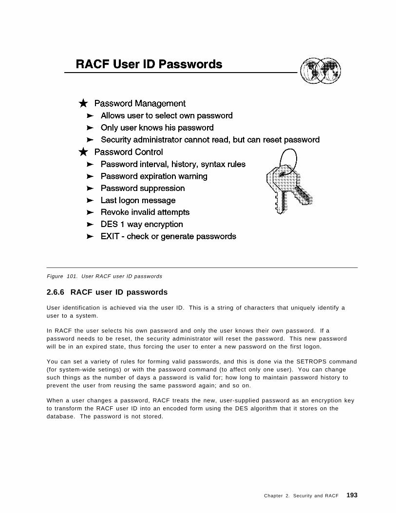
Figure 101. User RACF user ID passwords
2.6.6 RACF user ID passwords
User identification is achieved via the user ID. This is a string of characters that uniquely identify auser to a system.
In RACF the user selects his own password and only the user knows their own password. If apassword needs to be reset, the security administrator will reset the password. This new passwordwill be in an expired state, thus forcing the user to enter a new password on the first logon.
You can set a variety of rules for forming valid passwords, and this is done via the SETROPS command(for system-wide setings) or with the password command (to affect only one user). You can changesuch things as the number of days a password is valid for; how long to maintain password history toprevent the user from reusing the same password again; and so on.
When a user changes a password, RACF treats the new, user-supplied password as an encryption keyto transform the RACF user ID into an encoded form using the DES algorithm that it stores on thedatabase. The password is not stored.
Chapter 2. Security and RACF 193

2.6.6.1 Alternatives to password verification
1. RACF allows workstations and client machines in a client-server environment to use a PassTicketin place of a password. A PassTicket can be generated by RACF or by another authorizedfunction, and can be used only once on a given computer system, within ten minutes of generation.
2. RACF allows the use of an operator identification card (OIDCARD) in place of, or in addition to, thepassword during terminal processing. By requiring that a person not only know a password butalso furnish an OIDCARD, an installation has increased assurance that the user ID has beenentered by the proper user.
3. OS/390 UNIX users are also identified with numeric user identifiers (UIDs), and OS/390 UNIX groupsare identified with numeric group identifiers (GIDs). Unlike user names or group names, thesenumeric IDs can be shared by more than than one user but is not recommended.
4. In a client/server environment, RACF can identify a RACF user ID by extracting information fromthe digital certificate. A digital certificate or digital ID, issued by a certifying authority, containsinformation that uniquely identifies the client.
5. The Lotus Domino Go Webserver authenticates a client using the client ′s certificate and the SecureSockets Layer (SSL) protocol. Domino Go Webserver passes the client ′s digital certificate toOS/390 UNIX for validation. OS/390 UNIX passes the certificate to RACF. This means that the RACFuser ID and password of each client do not need to be supplied when accessing secure Webpages.
194 ABCs of OS/390 System Programming

Figure 102. How to use RACF ISPF panels
2.7 How to use RACF ISPF panels
If your installation has installed the RACF panels, you can use them to perform security tasks.
To get to the RACF panels, enter the command: ISPF
The Interactive System Productivity Facility (ISPF) primary menu appears; choose option R for RACF.
Note: Although this is the usual way to access RACF panels, your installation may have thisimplemented via a different path.
The RACF panel interface is similar in use to all other ISPF panel options, therefore we do not go intodetail here on to how to use it.
You can access help information for the RACF panels. Help panels exist for each individual panel. Ifyou have a question about the information you should provide on the panel,either press the PF1 key ortype HELP on the command line. The help panels give more information about the terms on the paneland the information you should enter.
Chapter 2. Security and RACF 195

Figure 103. RACF resource profi les
2.7.1 RACF resource profiles
RACF-protected resources can be divided into two categories: data sets and general resources.General resources are all of the resources that are defined in the class descriptor table. For example,general resources include DASD and tape volumes, load modules (programs), terminals, and others.
RACF maintains information entries called profiles in the RACF database. It uses them to protectDASD and tape data sets and general resources, such as tape volumes and terminals.
• Data set profiles contain security information about DASD and tape data sets.
• General resource profiles contain security information about general resources.
Each RACF-defined resource has a profile, though you can optionally use single profile to protectmultiple resources.
RACF commands or the RACF ISPF panels can be used to create and modify general resource profiles.
RACF provides discrete, generic, and grouped resource profiles for both data sets and generalresources, as follows:
Discrete Discrete profiles have a one-for-one relationship with a resource; one profile for eachresource. Discrete profiles provide very specific levels of control and should be used forsensitive resources. They protect only the one identified data set that is on the specifiedvolume or that spans specific volumes. For example, a single data set can be definedwith a discrete profile to allow access by one user.
196 ABCs of OS/390 System Programming
Generic Generic profiles have a one-for-many relationship. One profile controls access to one ormore resources whose names contain patterns or character strings that RACF uses toassociate them with each other. They contain a list of the authorized users and theaccess authority of each user. A single generic profile can protect many data sets thathave a similar naming structure. For example, all data sets that have a high-levelqualifier of SMITH and the characters DATA as a second-level qualifier can be controlledwith one generic profile.
Grouped Another type of RACF profile is the grouped profile. There may be no way to associatethe resources with a common access list based on patterns in the resource names. Inthis case, the many resource names can be associated with a single RACF profile throughthe use of a grouping profile that contains the names of the associated resources.
Some subsystems with high performance requirements, such as IMS/ESA, have theprofiles resident in the subsystem address space. These subsystems can save mainstorage by using grouped profiles.
Chapter 2. Security and RACF 197
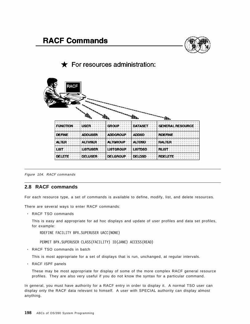
Figure 104. RACF commands
2.8 RACF commands
For each resource type, a set of commands is available to define, modify, list, and delete resources.
There are several ways to enter RACF commands:
• RACF TSO commands
This is easy and appropriate for ad hoc displays and update of user profiles and data set profiles,for example:
RDEFINE FACILITY BPX.SUPERUSER UACC(NONE)
PERMIT BPX.SUPERUSER CLASS(FACILITY) ID(JANE) ACCESS(READ)
• RACF TSO commands in batch
This is most appropriate for a set of displays that is run, unchanged, at regular intervals.
• RACF ISPF panels
These may be most appropriate for display of some of the more complex RACF general resourceprofiles. They are also very useful if you do not know the syntax for a particular command.
In general, you must have authority for a RACF entry in order to display it. A normal TSO user candisplay only the RACF data relevant to himself. A user with SPECIAL authority can display almostanything.
198 ABCs of OS/390 System Programming

Note: We say almost because RACF has another authority named AUDITOR who can uniquely displaycertain statistical data. A SPECIAL user can create AUDITOR authority, so the SPECIAL user remainsthe ultimate controller of RACF.
2.8.1.1 Using RACF commands with TSO/E
You can enter RACF TSO commands from the ready prompt or from Option 6 Command from the ISPFmenu.
You can get online help for RACF commands. To get online help for a command, type:
HELP command-name
For example, to see on-line help for the PERMIT command, enter:
HELP PERMIT
To limit the information displayed, use the SYNTAX operand on the HELP command:
HELP command-name SYNTAX
For example, to see only the syntax of the PERMIT command, enter:
HELP PERMIT SYNTAX
Here is a list of general use RACF commands:
PASSWORD Change password/interval
CONNECT Associate user with group
REMOVE Disassociate user from group
PERMIT Modify resource profile access list
SEARCH Locate RACF information
SETROPTS Set/modify RACF system options
RVARY Switch RACF databases
Abbreviations can be used for commands and parameters :
• AU for ADDUSER• LG for LISTGROUP• CO for CONNECT• ID for USERID• AC for ACCESS• INT for INTERVAL
Any TSO commands can be used in a batch job, using the JCL for executing the TSO monitor in batch;for example:
//P390S JOB 1,P390,MSGCLASS=X//TSOBAT01 EXEC PGM=IKJEFT01//SYSTSPRT DD SYSOUT=*//SYSPRINT DD SYSOUT=*//SYSUADS DD DSN=SYS1.UADS,DISP=SHR//SYSLBC DD DSN=SYS1.BRODCAST,DISP=SHR//SYSTSIN DD *LD DA(′ MARTIN.*′ ) AUTHUSERLU MARTIN/*
Chapter 2. Security and RACF 199

Where:
LD DA(′ MARTIN.*′ ) AUTHUSER - would list generic profile MARTIN andits access list
LU MARTIN - would display the basic RACF data for userid MARTIN
200 ABCs of OS/390 System Programming

Figure 105. How to add a user
2.8.2 How to add a user
When you define a user′s profile (using the ADDUSER command) or change a user′s profile (using theALTUSER command), you can specify the information contained in each field of each segment of theprofile.
The command adds a profile for the new user to the RACF database and creates a connect profile thatconnects the user to whichever default group you specify.
The user profile consists of a RACF segment and, optionally, other segments such as a TSO segment,a DFP segment, or an OMVS segment. You can use this command to define information in anysegment of the user′s profile.
The visual shows sample output from the following ADDUSER command when the LISTUSER is issued:
ADDUSER JAMES NAME(′ BROWN JAMES′ ) DFLTGRP(MFG)OWNER(ADMUSERS) PASSWORD(NEW2DAY)
This command adds a new user ID JAMES into default group MFG.
Chapter 2. Security and RACF 201

Figure 106. How to reset a password
2.8.3 How to reset a passwordA system administrator is often asked to reset a user′s password. There are two common reasons forthis:
1. The user forgot his password (or made too many errors when attempting change it), or 2. The user ID has been REVOKED for some reason.
You can use the RACF ISPF panels to reset passwords, but it is easier to use direct RACF TSOcommands. There are two relevant commands:
PASSWORD When used to reset another user′s password, the only option is to set the password equalto the user′s default group name. The default group name is often SYS1; if thePASSWORD command is used to reset a user′s password, the password will probably beSYS1. This has obvious security consequences.
ALTUSER You can select the password to assign when you use this command. Furthermore, youcan determine whether the password you set will be expired or not.
In both cases, the password is automatically marked as expired, by default. This means that the userwill be forced to select a new password the next time he logs onto the system. With the ALUcommand, you can also set an unexpired password, one that the user can use until he changes it forsome reason.
Before resetting a password, we suggest you always use the LISTUSER command to verify that theuser definition exists, and determine if the user is REVOKED. For example, in this case we wouldprobably use this command:
202 ABCs of OS/390 System Programming

ALU martin RESUME PASS(newpwd) <== if REVOKEDALU martin PASS(newpwd) <== if not REVOKEDALU martin PASS(newpwd) NOEXPIRED <== if not REVOKED
PASSWORD NOINTERVAL USER(martin) <== if you want this
You would need to tell Martin the new password you assigned. He will need it to log on, but will beforced to change it immediately to a password of his own selection unless you used the NOEXPIREDoption. The PASSWORD NOINTERVAL command will prevent this user′s password from ever expiring.1
You need SPECIAL authority to issue these commands.
2.8.3.1 How to reset a password with ISPF panels
You can also use the RACF ISPF panels to change or reset passwords. The end result is the same asif you used the direct commands shown above.
� �RACF - CHANGE USER JAMES
COMMAND ===>
ENTER THE DESIRED CHANGES:
OWNER ===> Userid or group name
USER NAME ===>
DEFAULT GROUP ===> Group name
PASSWORD ===> User′ s password OR use default ===>===> Re-enter password to verify
EXPIRED ===> Mark new password as expired ?
PASSWORD INTERVAL ===> 1 - 254 days, NO, or blank
REVOKE ===> YES, mm/dd/yy (date) or blank
RESUME ===> YES, mm/dd/yy (date) or blank
� �Figure 107. RACF Change User menu
The path to the appropriate RACF ISPF panels is:
ISPF Primary Option MenuRACF (select RACF from the primary ISPF menu)RACF - Services Option MenuUser Profiles and Your Own PasswordRACF - User Profile ServicesCHANGE (and enter target userid in the USER field)
This should produce the panel shown in the previous figure, and you would carry on from this point.Remember that whatever password you assign must be changed by the user when he logs onto the
1 Using this is very poor security, but may be appropriate in smaller, closed systems.
Chapter 2. Security and RACF 203

system the next time. This same panel, and follow-on panels shown after you press ENTER, can beused to change the same elements as the ALTUSER command.
204 ABCs of OS/390 System Programming

Figure 108. How to alter a user ID segment
2.8.4 How to alter a user ID segment
Use the ALTUSER command to change the information in a user′s profile, including the user′ssystem-wide attributes and authorities. The user profile consists of a RACF segment and, optionally,other segments such a TSO segment or a DFP segment. You can use this command to changeinformation in any segment of the user′s profile.
When you change a user′s level of authority in a group (using the AUTHORITY operand), RACF updatesthe appropriate group profile. When you change a user′s default universal access authority for a group(using the UACC operand), RACF changes the appropriate connect profile. For all other changes,RACF changes the user′s profile.
The visual shows sample output from the ALTUSER command:
ALTUSER JAMES AUDITOR
This command adds the attribute of AUDITOR to the user ID JAMES.
Chapter 2. Security and RACF 205

Figure 109. How to connect a user to a group
2.8.5 How to connect a user to a group
Use the CONNECT command to connect a user to a group, modify a user′s connection to a group, orassign the group-related user attributes. If you are creating a connection, defaults are available asstated for each operand. If you are modifying an existing connection, no defaults apply.
To use the CONNECT command, you must have at least one of the following:
• The SPECIAL attribute
• The group-SPECIAL attribute in the group
• The ownership of the group
• JOIN or CONNECT authority in the group
The visual shows sample output from the CONNECT command:
CONNECT JAMES GROUP(TEST)
This command connects user JAMES to group TEST.
206 ABCs of OS/390 System Programming

Figure 110. How to remove a user from a group
2.8.6 How to remove a user from a group
You can use the REMOVE command to remove a user from a group, and to assign a new owner to anygroup data set profiles the user owns on behalf of that group.
To use the REMOVE command, one of the following conditions must be true:
• You have the SPECIAL attribute.
• The group profile is within the scope of a group in which you have the group-SPECIAL attribute.
• You are the owner of the group.
• You have JOIN or CONNECT authority in the group.
The visual shows sample output from the REMOVE command:
REMOVE JAMES GROUP(TEST)
Chapter 2. Security and RACF 207

Figure 111. How to a change a user
2.8.7 How to a change a user ′s password interval
The interval indicates the number of days during which a password remains valid; the range is from 1through 254 days.
The value you specify here cannot exceed the value, if any, that your installation has specified usingthe INTERVAL operand on the SETROPTS command. The initial system default after RACF initializationis 30 days.
If you specify INTERVAL on the PASSWORD command without a change-interval value, RACF uses theinstallation-specified maximum.
The visual shows sample output from the PASSWORD command:
PASSWORD USER(JAMES) INTERVAL(60)
This command would set user ID James ′ password expiry date to 60 days. Overriding any systemdefault password expiring setting is set by the SETROPTS command.
208 ABCs of OS/390 System Programming

Figure 112. How to a delete a user
2.8.8 How to a delete a user
Use the DELUSER command to delete a user from RACF. This command removes the user′s profileand all user-to-group connections for the user. (The connect profiles define the user′s connections tovarious RACF groups.)
There are, however, other places in the RACF database where the user ′s user ID might appear, andthe DELUSER command does not delete the user ID from all these places. Specifically, the user couldbe the owner of a group, the owner of a user′s profile, the owner of a group data set, or in an accesslist for any resource. Before issuing DELUSER, you must first issue the REMOVE command to assignnew owners for any group data sets the user owns in groups other than his default group. You canuse the RACF Remove ID utility (IRRRID00) to remove all of the occurrences of a user ID. Forinformation on using the RACF Remove ID utility, see OS/390 Security Server (RACF) SecurityAdministrator ′s Guide, SC28-1915.
To use the DELUSER command, at least one of the following must be true:
• You must have the SPECIAL attribute.• The user profile to be deleted must be within the scope of a group in which you have the
group-SPECIAL attribute.• You must be the owner of the user′s profile.
The visual shows sample output from the DELUSER command:
DELUSER JAMES
Chapter 2. Security and RACF 209

This command deleted user ID James.
210 ABCs of OS/390 System Programming

Figure 113. RACF groups
2.9 RACF groups
With RACF, all defined users belong to at least one group. You can think of the groups forming ahierarchical or “tree” structure, where each group is owned by a superior group. Groups can alsoown resources as well as users in another group.
RACF has the following types of groups:
Administrative You can create a group simply as an administrative convenience. For example, youmight create a group to represent an organizational entity, such as a region or adivision.
With RACF delegation, you can create this kind of group for each group administrator.Operating from such groups, the group administrators can then define other groupsneeded by their local users.
Holding This is a technique that retains user definition centrally, yet allows the effective use ofgroup administrators to establish a holding group. You define all users centrally andinitially connect them to a group named HOLD with the minimum of authorities. HOLDdoes not appear in any access lists, and therefore has no real significance to the user.
Group administrators, to whom you give CONNECT (but not JOIN) authority, canconnect the appropriate users to the groups under their control and change the users ′default group name as appropriate. This technique allows the installation to assigncorrect account numbers and control other installation considerations while allowingflexibility in the grouping of the user population.
Chapter 2. Security and RACF 211

Data Control You can create a group to act as a control point for the protection of data. Forexample, by using the group SYS1, you can determine which users are permitted toprotect the SYS1 data sets. Only users with CREATE authority or higher in this groupcan protect system data sets. At your location, you might consider defining one suchgroup for every high level qualifier representing data that is to be protected.
Functional A group can represent a functional area of the installation for the purpose of datasharing. For example, a financial analyst might need to access a variety of resourcesacross many groups, such as accounting, payroll, marketing, and others. Of course,the owners of each resource could permit the financial analyst to access theirresources by placing the analyst ′s user ID on an access list. But if a new financialanalyst takes over the job, it is then necessary to add the new user ID to each RACFprofile. Likewise, the RACF profiles must be updated when the analyst no longer hasa need to access the data. This arrangement involves a great deal of unnecessaryactivity by the resource owners.
Instead, you can create a group that represents the financial analyst function andpermits access to the data defined to the group. Access to the entire range of datacan then be managed by controlling the user population in the defined group. Forcases involving one-time access, owners of the needed data would simply PERMITaccess by the defined group. Where appropriate, the group name could be included inprofile access lists to ensure automatic availability of needed data to the financialanalyst group. New financial analysts could be connected to the group, as required, togain access to the entire range of data. Likewise, analysts could be removed from thegroup whenever necessary. By controlling the user population of such a functionalgroup, resource profile changes on a day-to-day basis becomes unnecessary.
User You can define a group to serve as an anchor point for users who otherwise have nocommon access requirements. For example, engineers and scientists, as well asother problem-solving users, might have no need to access application-related data inthe system. Their only interest may be in their own personal data. You can place thisset of users in a single group that has no access to other data.
You can also define groups based on access level. For example, if PAY.DATA is aRACF-defined data set, two groups could be defined, PAYREAD and PAYUPDTE, bothof which would appear in the PAY.DATA access list, but with READ and UPDATEaccess, respectively. Any users requiring access would be connected as appropriate,by the group administrator.
212 ABCs of OS/390 System Programming

Figure 114. RACF group structure
2.9.1 RACF group structure
The group structure of RACF can be mapped to the organizational structure that exists at yourinstallation. That is, RACF conforms naturally to a tree structure of groups, where each group (exceptSYS1, which is predefined as the highest group) has a superior, or owning, group. Groups cancorrespond directly to business entities such as divisions, departments, and projects. Users can beconnected to one or more groups.
When you define a group, you should consider the basic purpose of the group. Is it an administrativegroup, a holding group, a data control group, a functional group, or a user group? When setting upRACF groups, keep in mind that the maximum number of users that you can connect to any one groupis approximately 5900.
You should map your groups to your organization′s structure and arrange them hierarchically, with theIBM-supplied SYS1 group as the highest group, so that each group is a subgroup of another group.
A user may be connected in more than one group (in the example, SALLY is connected to MFG andTEST groups).
In this visual: GROUP, DESIGN, TEST, and MFG are all owned by group POU. Tom is connected togroup POU as special. This gives Tom (who is the RACF administrator) control over all POU resourcesDESIGN, TEST, and MFG.
Chapter 2. Security and RACF 213

Figure 115. How to add a group
2.9.2 How to add a group
Use the ADDGROUP command to define a new group to RACF. The command adds a profile for thenew group to the RACF database. It also establishes the relationship of the new group to the superiorgroup you specify.
Group profiles consist of a RACF segment and, optionally, other segments such as DFP and OMVS.You can use this command to specify information in any segment of the profile.
To use the ADDGROUP command, you must meet at least one of the following conditions:
• Have the SPECIAL attribute• Have the group-SPECIAL attribute and the superior group is within your group-SPECIAL scope• Be the owner of the superior group• Have JOIN authority in the superior group
The visual shows sample output from the ADDGROUP command:
ADDGROUP EXPED OWNER(ADMGRPS) SUPGROUP(POU)
This command added a new group named EXPED and it is a subgroup to group POU.
214 ABCs of OS/390 System Programming

Figure 116. How to alter a group
2.9.3 How to alter a group
Use the ALTGROUP command to change:
• The superior group of a group• The owner of a group• The terminal indicator for a group• A model profile name for a group• The installation-defined data associated with a group• The default segment information for a group (for example, DFP or OMVS).
To change the superior group of a group, you must meet at least one of the following conditions:
• You must have the SPECIAL attribute• All the following group profiles must be within the scope of a group in which you have the
group-SPECIAL attribute:− The group whose superior group you are changing− The current superior group− The new superior group
• You must be the owner of, or have JOIN authority in, both the current and the new superior groups.
Note: You can have JOIN authority in one group and be the owner of, or have the group-SPECIALattribute in, the other group.
The visual shows sample output from the ALTGROUP command:
ALDGROUP EXPED SUPGROUP(KGN)
Chapter 2. Security and RACF 215

This command moved the group named EXPED from being a subgroup of group PGN to a subgroup togroup KGN.
216 ABCs of OS/390 System Programming

Figure 117. How to connect a user to a group
2.9.4 How to connect a user to a group
Use the CONNECT command to connect a user to a group, modify a user′s connection to a group, orassign the group-related user attributes. If you are creating a connection, defaults are available asstated for each operand. If you are modifying an existing connection, no defaults apply.
To use the CONNECT command, you must have at least one of the following:
• The SPECIAL attribute• The group-SPECIAL attribute in the group• The ownership of the group• JOIN or CONNECT authority in the group
You cannot give a user a higher level of authority in the group than you have.
The visual shows sample output from the CONNECT command:
CONNECT JAMES GROUP(EXPED)
This command connects user James to the EXPED group.
Chapter 2. Security and RACF 217

Figure 118. How to remove a user from a group
2.9.5 How to remove a user from a group
You can use the REMOVE command to remove a user from a group, and to assign a new owner to anygroup data set profiles the user owns on behalf that group.
The visual shows sample output from the REMOVE command:
REMOVE JAMES GROUP(EXPED)
This command removes user James from the EXPED group.
218 ABCs of OS/390 System Programming

Figure 119. How to delete a group
2.9.6 How to delete a group
Use the DELGROUP command to delete a group and its relationship to its superior group from RACF.
There are, however, other places in the RACF database where the group name might appear, andDELGROUP processing does not delete these other occurrences of the group name. For example, thegroup name could be in the access list for any resource. You can use the RACF Remove ID utility(IRRRID00) to remove all occurrences of a group name. For information on using the RACF Remove IDutility, see OS/390 Security Server (RACF) Security Administrator′s Guide, SC28-1915.
The visual shows sample output from the DELGROUP command:
DELGROUP EXPED
This command deletes the EXPED group.
Chapter 2. Security and RACF 219
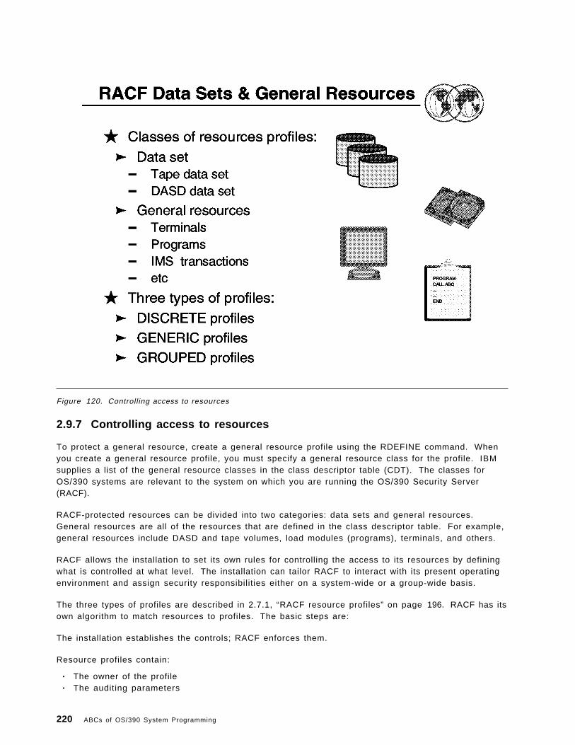
Figure 120. Controlling access to resources
2.9.7 Controlling access to resources
To protect a general resource, create a general resource profile using the RDEFINE command. Whenyou create a general resource profile, you must specify a general resource class for the profile. IBMsupplies a list of the general resource classes in the class descriptor table (CDT). The classes forOS/390 systems are relevant to the system on which you are running the OS/390 Security Server(RACF).
RACF-protected resources can be divided into two categories: data sets and general resources.General resources are all of the resources that are defined in the class descriptor table. For example,general resources include DASD and tape volumes, load modules (programs), terminals, and others.
RACF allows the installation to set its own rules for controlling the access to its resources by definingwhat is controlled at what level. The installation can tailor RACF to interact with its present operatingenvironment and assign security responsibilities either on a system-wide or a group-wide basis.
The three types of profiles are described in 2.7.1, “RACF resource profiles” on page 196. RACF has itsown algorithm to match resources to profiles. The basic steps are:
The installation establishes the controls; RACF enforces them.
Resource profiles contain:
• The owner of the profile• The auditing parameters
220 ABCs of OS/390 System Programming

• The Universal Access authority• An access list with users and groups• A “Warning” indicator• A security classification• A real-time notification information• An erase-on-scratch indication for data sets• A volume and a unit (if data set)• A security retention period (if tape data set)• Access statistics
Your installation can add new class descriptor table (CDT) entries or modify or delete existing entriesthat you have added in the installation-defined class descriptor table (ICHRRCDE). When you define anew resource class, you can optionally designate that class as either a resource group class or aresource member class. For a resource group class, each user or group of users that is permittedaccess to that resource group is permitted access to all members of the resource group. Note that foreach resource group class you create, you must also create a second class that represents themembers of the group.
Chapter 2. Security and RACF 221

Figure 121. RACF data sets and general resources
2.9.8 RACF data sets and general resources
RACF does the following to locate a resource profile:
• RACF will look for a discrete profile, if no discrete profile is found
• RACF will look for a generic profile and will then use the most qualified generic profile available.
See OS/390 Security Server (RACF) Security Administrator′s Guide, SC28-1915, for more detail on howthis works.
Some of the generic profile naming for general resources has been enhanced with some of the sameconcepts as generics for data set profiles as valid generic characters as follows:
* You may have an asterisk (*) within a profile name, representing one qualifier of a resource name,or specify * in the profile name to match more than one character in the same position of theresource name.
** You may also use a double asterisk (**) to represent zero or more qualifiers within a generalresource generic profile or at the end of such a profile, or specify ** in the profile name to matchmore than one character in the same position of the resource name. Use of the double asterisk(**) in general resource generic profiles is not controlled by the SETROPTS EGN option, whichapplies only to the data set profiles.
% Specify % any single non-blank character (except a period) in the same position of the resourcename
222 ABCs of OS/390 System Programming

For example, the following profile names all match in the first three character positions (A.B), and areshown in the order RACF examines them:
A.BA.B.BA.BAA.BZA.B0A.B9A.B&XA.B%A.B*
In the visual example, SALES.YEARLY.QUOTA
2.9.8.1 Choosing between discrete and generic data set profiles
Decide which type of profile to create as follows:
Generic Choose a generic profile for the following reasons:
• If you want to protect more than one data set with the same security requirements.
• If you have a single data set that might be deleted, then re-created, and you want theprotection to remain the same, you can create a fully qualified generic profile. Thename of a fully qualified generic profile matches the name of the data set it protects.Unlike a discrete profile, a fully qualified generic profile is not deleted when the data setitself is deleted.
Discrete Choose a discrete profile for the following reasons:
• To protect one data set that has unique security requirements. The name of a discreteprofile matches the name of the data set it protects.
• To allow changes to a data set profile to take effect immediately, without needing torefresh in-storage copies of the profile.
In the example on the visual, a resource manager issues a security check for the data setSALES.YEARLY.QUOTA. The visual shows the three different types of profiles that could bedefined in the RACF database:
1. A discrete profile 2. A fully qualified generic profile 3. Find the most specific generic profile
The example shows that RACF looks for a profile in the order shown. If no discrete profileis found, check for a fully qualified profile. If not found, then find the most specific genericprofile, which is the second one in the example, SALES.YEARLY.%%%%%.
Note: By using generic profiles, your installation can reduce both the number of profilesrequired to protect data sets and the size of the RACF database, thus making RACFprotection easier to administer. In addition, generic profiles are loaded into storage whenfirst needed, are not deleted when the data set they protect is deleted, and are notvolume-specific (that is, data sets protected by a generic profile can reside on any volume).
You can create a profile with a generic name when the following is true for the class of theprofile:
SETROPTS GENERIC(DATASET) option is in effect.
Not only does this option allow the creation of generic profiles, it also causes RACF to usegeneric profiles during authorization checking.
Chapter 2. Security and RACF 223

Figure 122. Defining data set profi les
2.9.9 Defining data set profiles
Use the ADDSD command to add RACF protection to data sets with either discrete or generic profiles.
Use the RDEFINE command to define to RACF all resources belonging to classes specified in the classdescriptor table. You can also use the RDEFINE command to create entries in the global accesschecking table and in the lists of security categories and security levels, and to define classes (asprofiles in the RACGLIST class) for which RACF saves RACLISTed results on the RACF database.
The RDEFINE command adds a profile for the resource to the RACF database in order to controlaccess to the resource. It also places your user ID on the access list and gives you ALTER authority tothe resource unless SETROPTS NOADDCREATOR is in effect.
Note: You cannot use the RDEFINE command to define users, groups, or data sets.
2.9.9.1 Data set profiles
By default, RACF expects a data set name (and the data set profile name) to consist of at least twoqualifiers. RACF also expects the high-level qualifier of the data set profile name to be either aRACF-defined user or a RACF-defined group name.
Each data set profile defined to RACF requires a RACF-defined user or group as the owner of theprofile. The owner (if a user) has full control over the profile, including the access list.
224 ABCs of OS/390 System Programming

If the owner of the data set profile is a group, users with group-SPECIAL in that group have full controlover the profile.
Ownership of data set profiles is assigned when the profiles are defined to RACF. Note that ownershipof a data set profile does not mean that the owner can automatically access that data set. To access adata set, the owner must still be authorized in the profile′s access list, unless the high-level qualifier ofthe profile name is the owner′s user ID.
2.9.9.2 Data set profile examples
The RDEFINE in the data set class, DATASET, specifies that no users have access to the data setexcept the creator of the profile since the universal access, UACC, is none.
To allow users to have access to the data set, the PERMIT command shown specifies that user IDJANE has only READ access to the data set, ACC(READ). User ID JANE exists in the access list for thedata set profile via the PERMIT command.
Chapter 2. Security and RACF 225

Figure 123. Data set profi le access list
2.9.10 Data set profile access list
When a user requests access to a RACF-protected resource (such as a data set), the resourcemanager issues a RACF authorization request. RACF then performs two checks.
Using the PERMIT command maintains a list of users and groups authorized to access a particularresource. RACF provides two types of access lists: standard and conditional.
Standard The standard access list includes the user IDs and group names authorized to accessthe resource and the level of access granted to each.
Conditional The conditional access list includes the user and group names authorized to access theresource and the level of access granted to each when a certain condition is met.
2.9.10.1 Types of access levels
ALTER ALTER allows users to read, update, delete, rename, move, or scratch the data set.
When specified in a discrete profile, ALTER allows users to read, alter, and delete theprofile itself including the access list.
ALTER does not allow users to change the owner of the profile using the ALTDSDcommand. However, if a user with ALTER access authority to a discrete data set profilerenames the data set, changing the high-level qualifier to his or her own user ID, both thedata set and the profile are renamed, and the OWNER of the profile is changed to the newuser ID.
226 ABCs of OS/390 System Programming

When specified in a generic profile, ALTER gives users no authority over the profile itself.
NONE The specified user or group is not permitted to access the resource or list the profile.
EXECUTE For a private load library, EXECUTE allows users to load and execute, but not to read orcopy programs (load modules) in the library.
READ Allows users to access the data set for reading only. (Note that users who can read thedata set can copy or print it.)
UPDATE Allows users to read from, copy from, or write to the data set. UPDATE does not,however, authorize a user to delete, rename, move, or scratch the data set.
CONTROL For VSAM data sets, CONTROL is equivalent to the VSAM CONTROL password; that is, itallows users to perform improved control interval processing. This is control-intervalaccess (access to individual VSAM data blocks), and the ability to retrieve, update, insert,or delete records in the specified data set.
For non-VSAM data sets, CONTROL is equivalent to UPDATE.
Chapter 2. Security and RACF 227

Figure 124. How to add a data set profi le
2.9.11 How to add a data set profile
When you define data set profiles to RACF, you can use either standard or nonstandard namingconventions. If you use nonstandard naming conventions, the data set naming convention table andthe single-level data set names option are ways to help “fit” RACF standard naming conventions.
The descriptions of naming conventions are followed by rules for protecting and allocating user andgroup data sets.
By default, RACF expects a data set name (and the data set profile name) to consist of at least twoqualifiers. RACF also expects the high-level qualifier of the data set profile name to be either aRACF-defined user or a RACF-defined group name.
This command added a generic profile for data sets with a high level qualifer of james.* (the *character is a valid generic character for more than one character in this position).
ADDSD ′ JAMES.*′
The visual shows sample output from the LISTDSD command:
228 ABCs of OS/390 System Programming

Figure 125. How to alter a data set profi le
2.9.12 How to alter a data set profile
Use the ALTDSD command to:
• Modify an existing discrete or generic data set profile.• Protect a single volume of either a multivolume tape data set or a multivolume, non-VSAM DASD
data set. At least one volume must already be RACF-protected.• Remove RACF-protection from either a single volume of a multivolume tape data set or a single
volume of a multivolume, non-VSAM DASD data set. You cannot delete the last volume from theprofile.
This visual shows a command to alter the auditing options for the previously data set, JAMES.*
ALTDSD′ JAMES.*′ AUDIT(S(U),F(R))
The command also specifies which new access attempts you want to log to the SMP data set.
SUCCESS S(U) Indicates that you want to log authorized accesses to UPDATE
FAILURES F(R) Indicates that you want to log detected unauthorized access attempts to read
The visual shows a sample output from the ALTDSD command, which shows the auditing options as:
SUCCESS(UPDATE),FAILURE(READ)
Chapter 2. Security and RACF 229

Figure 126. List a data set profi le matching a mask
2.9.13 List a data set profile matching a mask
The SEARCH command obtains a list of RACF profiles, users, and groups from the RACF DATABASEusing search criteria specified.
MASK specifies the strings of alphanumeric characters used to search the RACF database. This datadefines the range of profile names selected. The two-character strings together must not exceed 44characters for a tape or DASD data set name, or, for general resource classes, the length specified inthe class descriptor table.
The visual shows a SEARCH command with the search criteria, MASK.
SEARCH MASK(JAMES) CLASS(DATASET)
This command allows RACF to list profiles starting with the MASK, in this case JAMES.
A second example allows RACF to list all profiles containing the filter string.
SEARCH FILTER(JAMES) CLASS(DATASET)
230 ABCs of OS/390 System Programming

protected by a profile′.
Figure 127. List a catalogued data set
2.9.14 List a catalogued data set
The visual shows sample output from the LISTDSD command:
LISTDSD′ JAMES.*′ DSNS
This command allows RACF to list data sets protected by a profile (in this case, the JAMES.* data setprofile).
DSNS specifies that you want to list the cataloged data sets protected by the profile specified in theDATASET, ID, or PREFIX operand.
Chapter 2. Security and RACF 231

Figure 128. List who has access to a data set profi le
2.9.15 List who has access to a data set profile
The visual shows sample output from the PERMIT command:
PERMIT ′ JAMES.*′ ID(BILL,DESIGN) ACCESS(UPDATE)DSNS
This command allows Bill and the DESIGN group update access to the files protected by the James.*data set profile. Mark, Laurie, and Walt part of the DESIGN group will have UPDATE access, unless theaccess list contains their userid with another level of access.
PERMIT ′ JAMES.*′ ID(PAT) ACCESS(READ)DSNS
Pat will have read access to the files protected by the JAMES.* profile.
232 ABCs of OS/390 System Programming

Figure 129. How to add a general resource profi le
2.9.16 How to add a general resource profile
The visual shows sample output from the RDEFINE command:
RDEF PROGRAM MYMUSIC ADDMEM(′ JAMES.PGMLIB′ / VOL123/NOPADCHK)
This command defines a new resource profile called MYMUSIC that will run in PROGRAM class. Theprogram MYMUSIC is located in JAMES.PGMLIB member on DASD volume VOL123.
Setting NOPADCHK means that RACF will not check for program-accessed data sets when a user isexecuting the control programs.
Chapter 2. Security and RACF 233

Figure 130. How to change universal access authority
2.9.17 How to change universal access authorityThe visual shows sample output from the RALTER command:
RALT PROGRAM MYMUSIC UACC(READ)
This command sets the Universal Access Authority (UACC) to read. The UACC is the default access toa resource if the user or group is not specifically permitted access to the resource. The Altercommand has set the default access of MYMUSIC at READ.
234 ABCs of OS/390 System Programming

Figure 131. How to permit access to a resource profi le
2.9.18 How to permit access to a resource profile
The visual shows sample output from the PERMIT command:
PERMIT MYMUSIC CLASS(PROGRAM) ID(MARVIN) ACCESS(NONE)
Despite the UACC(READ) on the resource profile, MARVIN will not be able to access the resource asNONE as specified in the access list.
Chapter 2. Security and RACF 235

Figure 132. RACF monitor ing
2.10 RACF monitoring
For more immediate action, the user can request notification to the master terminal at the time ofviolation. A non-zero value for the SECCNT keyword of the SECURITY macro causes the masterterminal to be notified.
Because the number of violations for a large network may be high due to misspelled passwords,transaction codes, and commands, you can specify a threshold for notification. The master terminal isnot notified until the specified number of violations occur without a valid input from a given terminal.You specify 1 to 3 invalid entries as the violation limit. This eliminates or reduces the number ofnotifications caused merely by operator error, while still providing evidence of real attempts to avoidsecurity safeguards.
236 ABCs of OS/390 System Programming

Figure 133. RACF immediate notif ication - example 1
2.10.1 Example of RACF immediate notification - example 1
The explanation of the RACF message ICH408I is as follows:
ICH408I USER(userid) GROUP(group-name) NAME(user-name)
This message is issued when RACF detects an unauthorized request (a violation) made by a user orjob. The user and group indicated in the first line of the ICH408I message are the execution user IDand group ID under which the job was to run.
Chapter 2. Security and RACF 237

Figure 134. RACF immediate notif ication - example 2
2.10.2 Example of RACF immediate notification - example 2
The RACF message ICH70004I is as follows:
ICH70004I USER(accessor) GROUP(group-name)NAME(user-name) ATTEMPTED ′ access-type′ ACCESSOF ENTITY ′ resource-name′ IN CLASS ′ class-name′ AThh:mm:ss ON month day, year.
This message alerts a RACF user that an access violation has occurred against the indicated resource.This message is routed to the user specified in the NOTIFY field of the resource profile that denied theaccess.
238 ABCs of OS/390 System Programming

Figure 135. RACF auditing tools
2.11 RACF auditing tools
RACF auditing is basically verifying that the principals set forth by the installations security policy arenot compromised. The problem with auditing is being able to reduce the amount of information tosomething that can be easily analyzed.
Two types of auditing data exist:
1. Security data content from the RACF database, this is a static image or a snapshot of the systemparameters at any one time.
2. Security events data statistical information, such as the date, time, and the number of t imes aspecific resource was accessed by any one user.
RACF writes security log records when it detects:
• Unauthorized attempts to enter the system• Authorized or unauthorized attempts to enter RACF commands• RACF status changes• Warning mode resource access attempts• Failsoft operator access decisions• Optional authorized or unauthorized attempts to access RACF-protected resources
You can list the contents of these records to help you to detect possible security exposures or threatsand verify the security of the system.
Chapter 2. Security and RACF 239

Each of the following programs can help you accomplish your goals, depending on your specific needs:
• SMF data unload utility• RACF data unload utility• RACF report writer• Data security monitor (DSMON)
240 ABCs of OS/390 System Programming

Figure 136. SMF Data Unload Util ity
2.11.1 SMF Data Unload Utility (IRRADU00 program)
The SMF data unload utility processes SMF records and permits more complex auditing than the RACFreport writer.
Output from the SMF data unload utility can be:
• Viewed directly• Used as input for installation-written programs• Manipulated by sort/merge util it ies• Uploaded to a database manager, such as DB2
You can process complex inquiries and generate custom-tailored reports from the output of the SMFdata unload utility. These reports can be useful in identifying suspicious patterns of access byauthorized users that another program might miss. Because data is more often misused by authorizedusers than stolen by unauthorized users, reports like this are essential to security.
Chapter 2. Security and RACF 241

Figure 137. How to run the SMF Data Unload Util ity
2.11.2 How to run the SMF Data Unload Utility (IRRADU00)
Following is RACF SMF Data Unload Utility sample JCL:
//KHEWITT1 JOB (ITSO),′ SMF FLAT′ , MSGCLASS=X//SMFDUMP EXEC PGM=IFASMFDP//SYSPRINT DD SYSOUT=*//ADUPRINT DD SYSOUT=*//OUTDD DD DISP=(NEW,CATLG),DSN=KHEWITT.RACF.IRRADU00,// UNIT=SYSDA,SPACE=(CYL,(10,5),RLSE),// LRECL=5096,RECFM=VB//SMFDATA DD DISP=SHR,DSN=SYS1.SC42.MAN2//SMFOUT DD DUMMY//SYSIN DD *
INDD(SMFDATA,OPTIONS(DUMP))OUTDD(SMFOUT,TYPE(000:255))ABEND(NORETRY)USER2(IRRADU00)USER3(IRRADU86)
//SYSIN DD DUMMY
To display the active SMF data set, use the D SMF command from the system console.
242 ABCs of OS/390 System Programming

IEE974I 10.12.27 SMF DATA SETS 796NAME VOLSER SIZE(BLKS) %FULL STATUS
P-SYS1.SC42.MAN1 MVS004 1200 0 ALTERNATES-SYS1.SC42.MAN2 MVS004 1200 86 ACTIVES-SYS1.SC42.MAN3 MVS004 1200 0 ALTERNATE
MAN2 is the active SMF data set.
The output file in this example is KEWITT.RACF.IRRADU00.
Chapter 2. Security and RACF 243

Figure 138. RACF report wri ter
2.12 RACF report writer
The RACF report writer lists the contents of system management facility (SMF) records in a format thatis easy to read. It also uses the same SMF data to generate the following specialized reports:
• Reports that describe attempts to access a particular RACF-protected resource in terms of useridentity, number and type of successful accesses, and number and type of attempted securityviolations.
• Reports that describe user and group activity.
• Reports that summarize system use and resource use.
The RACF report writer is stabilized at the RACF 1.9.2 level, and is not able to report on many of thelater RACF functions.
244 ABCs of OS/390 System Programming

Figure 139. How to run RACF report wri ter
2.12.1 How to run RACF report writer
Following is RACF Report Writer sample JCL:
//KHEWITT1 JOB (ITSO),′ RACF FLAT′ , MSGCLASS=X//HEWITT EXEC PGM=IKJEFT01//SYSTSPRT DD SYSOUT=*//SYSPRINT DD SYSOUT=*//SYSTSIN DD *RACFRW DSNAME(′ KHEWITT.RACF.IRRADU00′ )LISTSUMMARY USEREND/*
The RACF report writer can also be run from the TSO command line.
Chapter 2. Security and RACF 245

Figure 140. The RACF Data Security Monitor
2.13 RACF Data Security Monitor
The RACF data security monitor (DSMON) enables you to verify the basic system integrity and datasecurity controls.
RACF auditors can use the DSMON reports to evaluate the level of security at the installation and tocompare the actual level of security at an installation with the planned level of security.
2.13.1.1 DSMON reports
DSMON produces the following reports:
• System report
• Group tree report
• Program properties table report
• RACF authorized caller table report
• RACF class descriptor table report
• RACF EXIT report
• RACF global access checking table report
• RACF user attribute report
• RACF user attribute report summary report
246 ABCs of OS/390 System Programming

• RACF Selected data set report
2.13.1.2 The System Report
The system report contains information such as the identification and model of the processor complex,and the name, version, and release of the operating system. This report also specifies the RACFversion and release number and whether RACF is active. If RACF is inactive, DSMON prints amessage that tells you whether RACF was not activated at IPL or was deactivated by the RVARYcommand.
2.13.1.3 The Group Tree Report
This report lists, for each requested group, all of its subgroups, all of the subgroups′ subgroups, and soon, as well as the owner of each group listed in the report, if the owner is not the superior group. Youcan use the group tree report to examine the overall RACF group structure for your system. You canalso determine the scope of the group for group related user attributes (group SPECIAL, groupOPERATIONS, and group AUDITOR).
2.13.1.4 The Program Properties Table Report
This report lists all of the programs in the MVS program properties table (PPT). The report alsoindicates, for each program, whether the program is authorized to bypass password protection andwhether it runs in a system key.
You can use the program properties table report to verify that only those programs that the installationhas authorized to bypass password protection are, in fact able to do so. Such programs are normallycommunication and database control programs and other system control programs.
You can also verify that only those programs that the installation has authorized are able to run in asystem key.
2.13.1.5 The RACF Authorized Caller Table Report
This report lists the names of all of the programs in the RACF authorized-caller table. The programs inthis table are authorized to issue REQUEST=VERIFY (which performs user verification) orREQUEST=LIST (which loads profiles into main storage).
You can use this report to verify that only those programs that are supposed to be authorized to modifyan ACEE (accessor environment element) are able to issue a REQUEST=VERIFY. This verification is aparticularly important security requirement because the ACEE contains a description of the currentuser. This description includes the user ID, the current connect group, the user attributes, and thegroup authorities. A program that is authorized to issue REQUEST=VERIFY could alter the ACEE tosimulate any user.
You can also use this report to verify that only those programs that are supposed to be authorized toaccess profiles are able to issue REQUEST=LIST. Because profiles contain complete descriptions ofthe characteristics that are associated with RACF-defined entities, you must carefully control access tothem.
Chapter 2. Security and RACF 247

2.13.1.6 The RACF Class Descriptor Table Report
This report lists, for each general resource class the class name, the default UACC, whether the classis active, whether auditing is being done, whether statistics are being kept, and whether OPERATIONSattribute users have access.
You can use the class descriptor table report to determine which classes (besides DATASET) aredefined to RACF and active, and therefore can contain resources that RACF protects.
2.13.1.7 The RACF Exits Report
This report lists the names of all of the installation-defined RACF exit routines and specifies the size ofeach exit routine module.
You can use the RACF exits report to verify that the only active exit routines are those that yourinstallation has defined. The existence of any other exit routines might indicate a system securityexposure, because RACF exit routines can be used to bypass RACF security checking. Similarly, if thelength of an exit routine module differs from the length of the module when it was defined by yourinstallation, the module might have unauthorized modifications.
2.13.1.8 The RACF Global Access Checking Table ReportThis report lists, for each resource class in the global access table, all of the entry names and theirassociated resource access authorities.
Because global access checking allows anyone to access the resource at the associated accessauthority, you should verify that each entry has an appropriate level of access authority.
The RACF Started Procedures Table Reports RACF generates two started procedures table reports.
If the STARTED class is active, the report uses the STARTED class profiles and contains the TRACEattribute. The trace uses module ICHDSM00.
If the STARTED class is not active, the trace uses the installation replaceable load module, ICHRIN03.
The reports list the procedure name, the user ID and group name to be associated with the procedure,and whether the procedure is privileged or trusted.
You can use the report to determine which started procedures are defined to RACF, and which havethe privileged attribute. If a started procedure is privileged or trusted, it bypasses allREQUEST=AUTH processing (unless the CSA or PRIVATE operand was specified onREQUEST=AUTH), including checks for security classification of users and data.
2.13.1.9 Selected User Attribute Report
The selected user attribute report:
Lists all RACF users with the SPECIAL, OPERATIONS, AUDITOR, or REVOKE attributes
Specifies whether they possess these attributes on a system-wide (user) or group level
Indicates whether they have any user ID associations
You can use this report to verify that only those users who need to be authorized to perform certainfunctions have been assigned the corresponding attribute.
248 ABCs of OS/390 System Programming
2.13.1.10 Selected User Attribute Summary Report
The selected user attribute summary report shows the number of installation-defined users and totalsfor users with the SPECIAL, OPERATIONS, AUDITOR, and REVOKE attributes, at both the system andgroup level. You can use this report to verify that the number of users with each of these attributes, oneither a system or group level, is the number that your installation wants. In particular, you shouldmake sure that you have assigned the SPECIAL attribute (on a system level) to at least one user andthe AUDITOR attribute (on a system level) to at least one user.
2.13.1.11 Selected Data Sets Report
This report lists the names of selected system data sets and, for each data set, specifies the criterionfor selection, the serial number of the volume on which it resides, whether the data set isRACF-indicated or RACF-protected, and the universal access authority (UACC). If a data set meetsmore than one selection criterion, there is a separate entry in the report for each criterion. Theselected data sets include system data sets, the MVS master catalog, user catalogs, the RACF primaryand backup data sets, and user-specified data sets.
You can use the selected data sets report to determine which of these data sets are protected byRACF and which are not. You can also check whether the UACC associated with each of the data setsis compatible with your installation ′s resource access control requirements.
Chapter 2. Security and RACF 249

Figure 141. How to run DSMON
2.13.2 How to run the DSMON program
DSMON runs as an authorized program facility (APF) authorized batch program. DSMON can also berun on TSO if SYS1.PARMLIB(IKJTSO00) is configured correctly.
Following is sample DSMON JCL:
//P390S JOB 1,P390,MSGCLASS=X//TSOBAT01 EXEC PGM=ICHDSM00//SYSPRINT DD SYSOUT=*//SYSUT2 DD SYSOUT=*//SYSIN DD *LINECOUNT 55FUNCTION allUSEROPT USRDSN sivle.memo.text
/*
250 ABCs of OS/390 System Programming

Figure 142. RACF Database Unload Util ity
2.14 RACF Database Unload Utility
The RACF Database Unload Utility (IRRDBU00 program) is used to unload data from the RACFdatabase (except password fields) into a flat file.
The output file from the database unload utility can be:
• Viewed directly
• Used as input to your own programs
• Manipulated with sort/merge util it ies
• Used as input to a database management system
Installations can produce reports that are tailored to their requirements.
Using the Database Unload Utility Output with DB2 you can use the DB2 Load Utility or its equivalent toprocess the records produced by the database unload utility. The definition and control statements fora DB2 to use this output, are shipped with OS/390 in the SYS1.SAMPLIB.
Chapter 2. Security and RACF 251

Figure 143. How to run the RACF Data Unload Util ity
2.14.1 How to run IRRDBU00
Following is RACF Data Unload Utility sample JCL:
//KHEWITT1 JOB (ITSO),′ RACF FLAT′ , MSGCLASS=X//UNLOAD EXEC PGM=IRRDBU00,PARM=NOLOCKINPUT//SYSPRINT DD SYSOUT=*//INDD1 DD DISP=SHR,DSN=SYS1.RACFESA//OUTDD DD DISP=(NEW,CATLG),DSN=KHEWITT.RACFDB.FLATFILE,// UNIT=SYSDA,SPACE=(CYL,(70,10),RLSE),// LRECL=4096,RECFM=VB//SYSIN DD DUMMY
The output file name in this example is KEWITT.RACF.IRRADU00. To display the active SMF data set,use the command D SMF.
252 ABCs of OS/390 System Programming

Chapter 3. OS/390 UNIX System Services
The OS/390 support for OS/390 UNIX System Services (OS/390 UNIX) enables two open systemsinterfaces on the OS/390 operating system:
• An application program interface (API)
The application interface is composed of C interfaces. Some of the C interfaces are managedwithin the C Run-Time Library (RTL), and others access kernel interfaces to perform authorizedsystem functions on behalf of the unauthorized caller.
With the API, programs can run in any environment, which includes batch jobs, jobs submitted byTSO/E users, most other started tasks, and in any other MVS application task environment. Aprogram can request:
− Only MVS services− Only OS/390 UNIX− Both MVS and OS/390 UNIX
• An interactive OS/390 shell interface
The OS/390 shell is modeled after the UNIX System V shell with some of the features found in theKorn Shell. As implemented for OS/390 UNIX services this shell conforms to POSIX standard1003.2, which has been adopted as ISO/IEC International Standard 9945-2: 1992.
The shell is a command processor that you use to:
− Invoke shell commands or utilities that request services from the system.
− Write shell scripts using the shell programming language.
− Run shell scripts and C-language programs interactively (in the foreground), in the background,or in batch.
− The OS/390 shell provides commands and utilities that give the user an efficient way to requesta range of services.
Copyright IBM Corp. 2000 253

Figure 144. Component support for UNIX services
3.1 Products and components with OS/390 UNIX
This visual shows the products, (RACF, TCP/IP, DFSMS, ADSM, RMF, TSO/E, and SMP/E) andcomponents (VLF, SMF, and WLM) used with OS/390 UNIX System Services.
OS/390 components
WLM The Work Load Manager (WLM) transaction initiators provide address spaces when programsissue the fork() or spawn() C function or OS/390 callable service.
VLF RACF allows caching of UID and GID information in the Virtual Lookaside Facility (VLF). Addthe following VLF options to the COFVLFxx member of SYS1.PARMLIB to enable the caching:
CLASS NAME(IRRUMAP)EMAJ(UMAP)
CLASS NAME(IRRGMAP)EMAJ(GMAP)
This will improve the performance of OS/390 UNIX.
SMF System Management Facility (SMF) collects data for accounting. SMF job and job-stepaccounting records identify processes by user, process, group, and session identifiers. Fieldsin these records also provide information on resources used by the process. SMF File Systemrecords describe file system events such as file open, file close, and file system mount,unmount, quiesce, and unquiesce.
254 ABCs of OS/390 System Programming

Figure 145. UNIX System Services
3.2 UNIX System Services
The name OpenEdition was changed to OS/390 UNIX System Services beginning with OS/390 Release5. UNIX System Services can be abbreviated OS/390 UNIX. OS/390 and OS/390 UNIX are Year 2000ready and require no migration action.
For more information about Year 2000 support, see The Year 2000 and 2-Digit Dates: A Guide forPlanning and Implementation, GC28-1251, and the Web site http://www.ibm.com/year2000/.
Chapter 3. OS/390 UNIX 255

Figure 146. POSIX standards overview
3.3 POSIX standards overview
The work on Portability Operating Systems Interface (POSIX) started as an effort to standardize UNIXand was performed by a workgroup under the Institute of Electrical and Electronical Engineers (IEEE).What they defined was an application programming interface which could be applied not only to UNIXsystems but to other operating systems like MVS.
POSIX is not a product. It is an evolving family of standards describing a wide spectrum of operatingsystem components ranging from C language and shell interfaces to system administration.
The POSIX standard is sponsored by the International Organization for Standardization (ISO) and isincorporated into X/Open Portability Guides (XPG). Each element of the standard is defined by a 1003.*number.
POSIX defines the interfaces and not the solution or implementation. In this way POSIX can besupported by any operating system. Implementation of POSIX can be different in areas such asperformance, availability, recoverability, and so on. All POSIX compliant systems are not the samealthough they all support basically the same interface.
Many people think open means UNIX. Although POSIX evolved from UNIX, it ′s not the same as UNIX.
The support for open systems in OS/390 is based on the POSIX standard. POSIX is a part or a subsetof the XPG standard defined by X/Open.
256 ABCs of OS/390 System Programming

Figure 147. X/Open Portability Guide Issue 4/4.2
3.4 X/Open Portability Guide
OS/390 UNIX was originally implemented in MVS/ESA 4.3 as OpenEdition and supported the POSIXstandards (1003.1, 1003.1a, 1003.1c, and 1003.2) with approximately 300 functions. In MVS/ESA 5.2.2many additional functions were added to meet the XPG4 requirements.
In MVS/ESA 5.2.2 the number of functions included in the OpenEdition implementation was more than1100. This incorporated the full X/Open Portability Guide issue 4 (XPG4) and over 90 percent of thesingle UNIX specification as defined in XPG4.2. The remaining functions were added afterwards and soOpenEdition became branded as a UNIX system.
The XPG4.2 support includes all commands and utilities, most of the additional C services defined inthe standard and curses, which was included in specification 1170 but not in the XPG4.2 itself. Cursesis the UNIX multicolor, multi-language screen control package which comes from the Novell SVIDEdition 3 package.
Since OS/390 R2 the following items were added: STREAMS, X/Open Transport Interface (XTI), XPG4.2regular expressions, XPG4.2 context switching, and XPG4.2 behavior specific to sockets.
Since 1992, multiple standards organizations have been involved in tasks to standardize UNIX andprovide a set of open systems interface specifications. Many of these organizations cooperated andmany vendors fully supported their efforts to create a UNIX-based set of application programminginterfaces.
Chapter 3. OS/390 UNIX 257

MVS started out to be a POSIX compliant system. This support has been extended to support theX/Open definitions of the X/Open Portability Guide issue 4 and 4.2.
The advantage of this goal was the portability of programs developed to these standards and thesharing of development across heterogeneous platforms. Also included in XPG4.2 were the protocolsand methods for communicating between programs on different platforms. This then addressed both,the issues of portability and the interoperability which was defined earlier in this topic as therequirement of open systems.
Since 1996, OS/390 R2 has been UNIX branded.
258 ABCs of OS/390 System Programming

Figure 148. OS/390 operating system with OS/390 UNIX
3.5 OS/390 operating system with OS/390 UNIX
The OS/390 support for OS/390 UNIX System Services (OS/390 UNIX) enables two open systemsinterfaces on the OS/390 operating system:
• An application program interface (API)• An interactive OS/390 shell interface
With the APIs, programs can run in any environment—including in batch jobs, in jobs submitted byTSO/E users, and in most other started tasks—or in any other MVS application task environment. Theprograms can request:
• Only MVS services• Only OS/390 UNIX• Both MVS and OS/390 UNIX
The shell interface is an execution environment analogous to TSO/E, with a programming language ofshell commands analogous to the Restructured eXtended eXecutor (REXX) language. The shell workconsists of:
• Programs run by shell users
• Shell commands and scripts run by shell users
• Shell commands and scripts run as batch jobs
Chapter 3. OS/390 UNIX 259

To run a shell command or util ity, or any user-provided application program written in C or C++, youneed the C/C++ run-time library provided with the Language Environment (LE).
260 ABCs of OS/390 System Programming

With the OS/390 UNIX System Services Application Services, users can:
• Request services from the system through shell commands. Shell commands are like TSO/Ecommands.
• Write shell scripts to run tasks. Shell scripts are analogous to REXX EXECs.
• Run programs interactively (in the foreground) or in the background.
Many users use similar interfaces on other systems, such as AIX for the RISC System/6000 or UNIX,and use terminology different from OS/390 terminology. For example, they refer to virtual storage asmemory. The work done by their system administrators is handled by system programmers in anOS/390 system. To help you understand these users, this book and its glossary indicate equivalentterms and phrases.
Application programmers are likely to do the following tasks when creating UNIX-compliant applicationprograms:
• Design, code, and test the programs on their workstations using XPG4 UNIX-conforming systems.
• Send the source modules from the workstation to OS/390.
• Copy the source modules from the OS/390 data sets to HFS files.
• Compile the source modules and link-edit them into executable programs.
• Test the application programs.
• Use the application programs.
An OS/390 UNIX program can be run interactively from a shell in the foreground or background, run asan OS/390 batch job, or called from another program. The following types of applications exist in anOS/390 system with OS/390 UNIX:
• Strictly conforming XPG4 UNIX-conforming applications• Applications using only kernel services• Applications using both kernel and OS/390 services• Applications using only OS/390 services
An OS/390 program submitted through the job stream or as a job from a TSO/E session can requestkernel services through the following:
• C/C++ func t i ons• Shell commands, after invoking the shell• Callable services
At the first request, the system dubs the program as an OS/390 UNIX process, unless it is aPOSIX(OFF) program (which is not dubbed).
With the OS/390 UNIX System Services application services, users can:
• Request services from the system through shell commands. Shell commands are like TSO/Ecommands.
• Write shell scripts to run tasks. Shell scripts are analogous to REXX EXECs.
• Run programs interactively (in the foreground) or in the background.
Chapter 3. OS/390 UNIX 261

Figure 149. OS/390 UNIX programs (processes)
3.5.1 OS/390 UNIX programs (processes)
A process is a program using kernel services. The program can be created by the fork() function, forkcallable service, or spawn() function; or the program can be dubbed because it requested kernelservices. The three types of processes are:
• User processes, which are associated with a program or a shell user
• Daemon processes, which perform continuous or periodic system-wide functions, such as printerspooling
• Kernel processes, which perform system-wide functions for the kernel such as cleaning up zombieprocesses (init process)
When you enter a shell command, you start a process that runs in an MVS address space. When youenter that command, the OS/390 shell runs it in its own process group. As such, it is considered aseparate job and the shell assigns it a job identifier—a small number known only to the shell. (A shelljob identifier identifies a shell job, not an MVS job.) When the process completes, the system displaysthe shell prompt.
UNIX programs running in MVS address spaces use or access the following:
A S M / C + + These programming languages can be used to create the programs.
SAF A security product is required when running UNIX System Services. SAF is theinterface to RACF, Top Secret, or ACF2.
262 ABCs of OS/390 System Programming

BPXPRMxx This parmlib member determines the number of processes that may be started inthe OS/390 system.
MVS data sets UNIX programs may access MVS data sets.
HFS files UNIX programs may access HFS files.
TCP/IP Workstation users may enter the shell environment by using rlogin or telnet in aTCP/IP network. User-written applications may use TCP/IP as a communicationvehicle.
VTAM Workstation users may access TSO/E through VTAM. OS/390 UNIX is thenaccessed from TSO/E.
The system also assigns a process group identifier (PGID) and a process identifier (PID). When onlyone command is entered, the PGID is the same as the PID. The PGID can be thought of as asystem-wide identifier. If you enter more than one command at a time using a pipe, several processes,each with its own PID, will be started. However, these processes all have the same PGID and shell jobidentifier. The PGID is the same as the PID for the first process in the pipe.
Process identifiers associated with a process are as follows:
PID A process ID (PID) is a unique identifier assigned to a process while it runs. When theprocess ends, its PID is returned to the system. Each time you run a process, it has adifferent PID (it takes a long time for a PID to be reused by the system). You can use the PIDto track the status of a process with the ps command or the jobs command, or to end aprocess with the kill command.
PGID Each process in a process group shares a process group ID (PGID), which is the same as thePID of the first process in the process group. This ID is used for signaling related processes.
If a command starts just one process, its PID and PGID are the same.
PPID A process that creates a new process is called a parent process; the new process is called achild process. The parent process ID (PPID) becomes associated with the new child processwhen it is created. The PPID is not used for job control.
Chapter 3. OS/390 UNIX 263

Figure 150. Create a process
3.5.2 Create a process
Fork() is a POSIX/XPG4 function which creates a duplicate process referred to as a child process. Theprocess that issues the fork() is referred to as the parent process.
With OS/390 UNIX a program that issues a fork() function creates a new address space which is a copyof the address space where the program is running. The fork() function does a program call to thekernel which uses WLM/MVS facilities to create the child process. The contents of the parent addressspace are then copied to the child address space.
After the fork() function, the program in the child AS will start at the same instruction as the program inthe parent AS. Control is returned to both programs at the same point. The only difference that theprogram sees is the return code from the fork() function. A return code of zero is returned to the childafter a successful fork(). All other return codes are valid only for the parent.
A process will be created by using any of the following methods:
• C fork() function: Will create a child process which is identical to the parent process in a newaddress space scheduled by the Workload Manager (WLM).
• C spawn() function: Will create a child process which will be executing a different program than theparent, either in a new address space scheduled by WLM, or in the same address space as theparent process (local spawn).
264 ABCs of OS/390 System Programming

• OS/390 UNIX callable services: When a program uses an OS/390 UNIX assembler callable service,the OS/390 address space will be dubbed an OS/390 UNIX process. The address space will get aPID. The dub will not result in a new address space.
The kernel interfaces to WLM to create the new address space for a fork or spawn. WLM uses an IBMsupplied procedure BPXAS to start up a new address space. This new address space will theninitialize the UNIX child process to run in the address space. After the child process completes, thisaddress space can be reused for another fork or spawn. If none is waiting, BPXAS will time out afterbeing idle for 30 minutes.
To be able to decide useful values for the BPXPRMxx keywords which affect process resources, it isnecessary to understand how OS/390 UNIX processes are created and which functions can create aprocess.
When the program “prog1” in the parent address space (AS) issues the fork() function, the kernel iscalled to perform the action. The kernel calls the Workload Manager (WLM) to provide a new addressspace.
Once the child address space has been created, the child gets the required storage from a STORAGErequest. The kernel then copies the contents of the parent AS to the child AS using the MVCLinstruction. Once the copy has been completed, a short conversation between the kernel and the childprocess takes place. At this point, both the parent and child process are activated. The program inthe child AS gets control at the same point as the program in the parent AS. The only difference is thereturn code from the fork() function.
The child address space is almost an identical copy of the parent address space. User data, forexample private subpools, and system data, like RTM (Recovery Termination Management) controlblocks, are identical.
Any linkage stack in the parent is not carried over to the child. Also, dataspaces and hiperspaces arenot carried over since access list and access register contents are not copied. Internal timers togetherwith SMF and SRM accounting data are set to zero in the child address space.
HFS files are allocated to the kernel and I/O is done by calling the kernel. On a fork(), all open filesare inherited by the child address space. The child does not inherit any file locks for the HFS files.
MVS data sets are allocated to an individual address space, and after a fork() the child address spacedoes not have access to the MVS data sets allocated by the parent.
The visual shows two of the methods of creating processes. The reason for reviewing how processesare created is that WLM is used for scheduling an AS for the functions that create a child process in aseparate AS.
The OS/390 UNIX kernel will receive the requests for creating a new process, and depending onwhether the process will be located in a new AS, the kernel will ask WLM to schedule an addressspace. If a new address space is not required the kernel will create a child process in the same AS asthe parent.
The BPXAS address space is very similar to a JES2 initiator—have a look at the procedure in the nextfew pages. It actually enters the system as a started task. When it starts to run, a child processcreated by the kernel, it becomes a UNIX unit of work. When the child process completes, if there is nofurther work, the BPXAS reverts to an STC and waits on further fork/spawn work from WLM. If nothingappears for 30 minutes, the address space goes away. However, if you want to bring OS/390 downquickly, you need a way of quickly stopping all outstanding BPXAS address spaces.
Chapter 3. OS/390 UNIX 265

3.5.2.1 fork() function
The fork() function comes from UNIX and the implementation in OS/390 is a very resource consumingfunction. The fork() function creates a new child process which is an identical copy of the parentprocess, and the child process will be executing the same program as the parent. Storage areas arecopied from the parent to the child using MVCL. However, OS/390 UNIX provides the capability ofusing shared pages instead of copying the storage. In most cases where a fork() is used, the functionexec() follows immediately to start a new program in the child process. Because of this, it seems quiteunreasonable to copy all the storage and get rid of it without using it. Using shared pages is onesolution and how to activate that will be covered in the customization unit.
266 ABCs of OS/390 System Programming

Figure 151. OS/390 UNIX processes
3.5.3 OS/390 UNIX processes
OS/390 UNIX uses processes to run programs, and to associate resources to the programs. An OS/390address space can contain one or multiple processes.
A process is created by another process, or by a request for an OS/390 UNIX service. The process thatcreates a new process is called a parent process and the new process is called a child process. Therewill be a hierarchy of processes in the system.
Every process is identified by a process ID (PID) and is associated with its parent process by a parentprocess ID (PPID).
OS/390 UNIX supports processes that run in unique address spaces. These would be created by fork()and exec() services. It also supports local processes. These will share an address space and arecreated by the spawn() service.
The use of processes comes from UNIX where a process is used for executing some work. In the firstOS/390 UNIX release, a process was the same as an address space. Since later releases of OS/390UNIX provide the capability of having multiple processes within an address space, it is more suitable tocompare a process to a task in OS/390. OS/390 UNIX was changed to allow multiple processes withinan address space to save resources and improve performance.
The OS/390 UNIX shell is a large consumer of processes. The shell will create a new process foralmost each shell command a user executes. The process will only exist as long as it takes for thecommand to execute. This concept comes from UNIX. With later releases of OS/390 UNIX more
Chapter 3. OS/390 UNIX 267

commands are inline commands, which means they will not be executed in a separate process. Theshell will also use the capability of having multiple processes within the user shell process so that theshell commands which will execute in a different process will still be in the same AS.
A process can create one or more child processes, and the child processes can be parent processesof new child processes, thus creating a hierarchy of related processes. The PPID maintains therelationship between processes. Usually, a process creates a child process to perform a separate task,for example a shell command. The child process ends when the task is completed while the parentprocess continues to execute. If for some reason a parent process should terminate before a childprocess, the child process will become an orphan process. Orphan processes are inherited by the firstprocess created in the system called the “init” process.
268 ABCs of OS/390 System Programming

Figure 152. OS/390 UNIX components
3.5.4 OS/390 UNIX components
OS/390 UNIX offers open interfaces for applications and interactive users on an OS/390 system. TheOS/390 UNIX components and their functions are:
• The OS/390 UNIX kernel
At system IPL time, kernel services are started automatically. The kernel provides OS/390 UNIXSystem Services in answer to requests from programs and the shell. The kernel manages the filesystem, the communications, and the program processes.
In an OS/390 UNIX system the file system is part of the kernel. In an OS/390 UNIX environment thefile system is also considered part of the kernel because it is allocated to the kernel. The supportfor the file system is provided by the DFSMS/MVS product. The visual showing the file system aspart of the kernel shows a logical view of the solution.
OS/390 UNIX requires MVS/ESA SP 4.3 or higher. The hierarchical file system is shipped as part ofDFSMS/MVS.
The POSIX standard introduces a completely new terminology in the MVS environment. A typicalUNIX operating system consists of a kernel which interfaces directly with the hardware. Built onthe kernel is the shell and utilities layer that defines a command interface. Then there areapplication programs built on the shell and utilities.
The OS/390 UNIX API conforms to the POSIX and XPG4 standard. OS/390 was branded as a UNIXsystem by the Open Group in 1996. To support the APIs, the OS/390 system must provide some
Chapter 3. OS/390 UNIX 269

system services which are included in the kernel, such as the file system and communicationservices.
Daemons are programs that are typically started when the operating system is initialized andremain active to perform standard services. Some programs are considered daemons thatinitialize processes for users even though these daemons are not long-running processes. OS/390UNIX supplies daemons that start applications and start a user shell session when requested.
• The OS/390 UNIX shell and utilities
An interactive interface to OS/390 UNIX services which interprets commands from interactive usersand programs.
The shell and utilities component can be compared to the TSO function in OS/390.
• The OS/390 UNIX debugger (dbx)
The dbx debugger is not part of the POSIX standard. It is based on the dbx debugger that is wellknown in many UNIX environments.
The OS/390 UNIX debugger is a tool which application programmers can use to interactively debuga C program. The debugger is based on the dbx debugger which is common in many UNIXenvironments.
• The C/C++ compiler and C run-t ime l ibraries
The C/C++ compiler and C run-time libraries are needed to make executables that the kernelunderstands and can manage.
• DFSMS/MVS
DFSMS/MVS manages the hierarchical file system (HFS) data sets that contain the file systems. Touse kernel services in full-function mode, SMS must be active.
Network File System (NFS) enables users to mount file systems from other systems so that the filesappear to be locally mounted. You end up with a mixture of file systems that come from systemswhere the UIDs and GIDs may be independently managed.
• Language Environment (LE)
To run a shell command or util ity, or any user-provided application program written in C or C++,you need the C/C++ run-time library provided with Language Environment.
The C compiler and LE feature (Language Environment) library are changed and extended toinclude support for the POSIX and XPG4 C function calls. The LE product provides a commonrun-time environment and language-specific run-time services for compiled programs.
• DCE services
DCE services are part of the OS/390 base and are exploiters of the POSIX and XPG servicesprovided by OS/390 UNIX.
270 ABCs of OS/390 System Programming

Figure 153. Hierarchical f i le system (HFS)
3.6 Hierarchical file system (HFS)
The OS/390 UNIX file system is hierarchical and byte-oriented. Finding a file in the file system is doneby searching a directory or a series of directories. There is no concept of an OS/390 catalog thatpoints directly to a file.
A path name identifies a file and consists of directory names and a file name. A fully qualified filename which consists of the name of each directory in the path to a file plus the file name itself, can beup to 1023 bytes long.
The hierarchical file system allows for file names in mixed case.
The hierarchical file system (HFS) data set which contains the hierarchical file system is an OS/390(MVS) data set type.
The file system is very similar to hierarchical file systems on UNIX, DOS, and OS/2. The visual showsan example of a hierarchical file system structure.
The files in the hierarchical file system are sequential files, and they are accessed as byte streams. Arecord concept does not exist with these files other than the structure defined by an application.
The path name is constructed of individual directory names and a file name separated by theforward-slash character, for example, “/dir1/dir2/dir3/myfile.”
Chapter 3. OS/390 UNIX 271

Like UNIX, OS/390 UNIX is case sensitive to file and directory names. For example, in the samedirectory the file “MYFILE” is a different file than “myfile.”
HFS data sets and OS/390 data sets can reside on the same SMS-managed DASD volume.
The integration of the HFS file system with existing MVS file system management services providesautomated file system management capabilities which may not be available on other POSIX platforms.This allows file owners to spend less time on tasks such as back up and restore of entire file systems.
272 ABCs of OS/390 System Programming

Figure 154. HFS data set
3.6.1 HFS data sets
An OS/390 UNIX hierarchical file system is contained in a data set type called HFS. An HFS data setmust reside on an SMS-managed volume, and it is a single volume data set. HFS data sets can residewith other OS/390 data sets on SMS-managed volumes. Multiple systems can share an HFS data set ifit is mounted in read-only mode.
An HFS data set can have up to 123 extents, and the maximum size of the data set is one physicalvolume. For a 3390-Model 3 the maximum size is 2.838 GB. HFS data sets can only be accessed byOS/390 UNIX.
An HFS data set is allocated by specifying HFS in the DSNTYPE parameter. You can also define a dataclass for HFS data sets. All HFS data sets must be system-managed, and an individual HFS data setcan reside on only one DASD volume.
RACF or an equivalent security product must be installed and active on your system to use OS/390UNIX or HFS data sets.
An HFS data set is an OS/390 data set, but it cannot be accessed by traditional OS/390 services likeOPEN. Only OS/390 UNIX knows about the internal structures in the HFS data set which makes up ahierarchy of directory and files similar to the file system in OS/2, DOS, or UNIX. An HFS data set mustbe an SMS-managed data set.
The OS/390 UNIX file system is composed of multiple HFS data sets connected to each other in ahierarchy. On top of the hierarchy is the root file system. The root file system contains system
Chapter 3. OS/390 UNIX 273

directories and files. Most installations will have user data in separate HFS data sets which areconnected to the root. Connecting a file system to another is called “mounting.”
274 ABCs of OS/390 System Programming

Figure 155. DFSMSdss enhancement
3.6.2 DFSMSdss enhancement for HFS data sets
Before OS/390 R7, the maximum size of the HFS was one physical volume. For the 3390-Model 3DASD the maximum size was 2.8 GB.
OS/390 R7 now supports multivolume access up to 59 physical volumes. To make this clearer:
59 * 2.8 GB = 165.2 GB !!
This is only for one HFS data set. Imagine the possibilities if you are mounting HFS data in addition tothe root HFS!
Chapter 3. OS/390 UNIX 275

Figure 156. Naming convention for HFS
3.6.3 HFS naming convention
On this visual, you see a recommended naming convention for HFS data sets. This convention isbased on practical experience, and takes into consideration a sysplex naming convention.
The first OMVS is used to assign a storage class through the SMS ACS routines. The <SYSNAME> isthe name of the system where this HFS will be mounted for use. The <SYSR1> is the systemresidence volume used to identify the root HFS in a system, where you can have different releases ofOS/390. If you want to switch the system without renaming the HFS data set, then use this qualifier.The prod_name describes the product name like root, Java, DCE, and so on. The last qualifier tellsyou that this file is an HFS, and not, for example, a source file for HFS.
Some examples:
• OMVS.TC1.TRNRS1.ROOT.HFS
• OMVS.TC1.TIVOLI.HFS
• OMVS.PROD.ETC.HFS
• OMVS.TEST.TMP.HFS
Note: The <SYSR1> name is dropped for HFS data sets that are not tied to the SYSRES volume.
You need to have the SYSRES volser as part of the HFS root data set because you need to keep trackof the SMP/E configuration or environment. This HFS root data set is part of most MVS installation
276 ABCs of OS/390 System Programming

builds for SMP/E target zones based on SYSRES name. Therefore, adding the SYSRES name to theHFS data set name will help you keep your SMP/E environment workable.
Chapter 3. OS/390 UNIX 277

Figure 157. Comparison of fi le systems
3.6.4 Comparison of file systems
The OS/390 master catalog is analogous to the root directory in a hierarchical file system.
The user prefix assigned to OS/390 data sets points to a user catalog. The user catalog is organizedanalogous to a user directory (/u/ibmuser) in the file system. Typically, one user owns all the datasets whose names begin with his user prefix. For example, the data sets belonging to the TSO/E userID ibmuser all begin with the prefix ibmuser. There could be data sets named IBMUSER.C, andIBMUSER.C(PGMA).
In the file system, ibmuser would have a user directory named /u/ibmuser. Under that directory therecould be subdirectories named /u/ibmuser and /u/ibmuser/c/pgma.
Of the various types of OS/390 data sets, a partitioned data set (PDS) is most akin to a user directoryin the file system. In a partitioned data set such as IBMUSER.C, you could have members PGMA,PGMB, and so on. For example, you could have IBMUSER.C(PGMA) and IBMUSER.C(PGMB). Asubdirectory such as /u/ibmuser/c can hold many files, such as pgma, pgmb, and so on.
278 ABCs of OS/390 System Programming

Figure 158. OS/390 UNIX interactive interfaces
3.7 OS/390 UNIX interactive interfaces
The visual shows an overview of the two interactive interfaces, OS/390 UNIX shell and ISHELL. Inaddition, there are some TSO/E commands to support OS/390 UNIX, but they are limited to certainfunctions such as copying files, and creating directories
3.7.1.1 OS/390 UNIX shell
The OS/390 UNIX shell is based on the UNIX System V shell and has some of the features from theUNIX Korn shell. The POSIX standard distinguishes between a command which is a directive to theshell to perform a specific task, and a utility which is the name of a program callable by name from theshell. To the user, there is no difference between a command and a utility.
Interactive users of OS/390 UNIX have a choice between using a UNIX-like interface (the shell), a TSOinterface (TSO commands), and an ISPF interface (ISPF CUA dialog). With these choices, users canchoose the interface which they are most familiar with and get a quicker start on OS/390 UNIX.
The OS/390 UNIX shell provides the environment that has the most functions and capabilities. Shellcommands can easily be combined in pipes or shell scripts and thereby become powerful newfunctions. A sequence of shell commands can be stored in a text file which can be executed. This iscalled a shell script. The shell supports many of the features of a regular programming language.
Chapter 3. OS/390 UNIX 279

3.7.1.2 The ISHELL
There are some TSO commands which provide support for UNIX System Services. An importantcommand is the OMVS command which is the command to invoke the OS/390 UNIX shell. The ISHELLcommand will invoke the ISPF shell. The ISHELL is a good starting point for users familiar with TSOand ISPF that want/need to use OS/390 UNIX. The ISHELL provides CUA panels where users can workwith the hierarchical file system. There are also panels for mounting/unmounting file systems and fordoing some OS/390 UNIX administration.
The ISHELL is an ISPF dialog for users and system administrators which can be used instead of shellcommands to perform many tasks related to file systems, files, and OS/390 UNIX user administration.
3.7.1.3 TSO REXX
The REXX support for OS/390 UNIX is not really an interactive interface, but I chose to introduce it heresince it is most often used in TSO or in the shell. The SYSCALL environment is not built into TSO/E,but an external function call called SYSCALLS will initialize the environment. Note that the shell is theinitial host environment, which means that the SYSCALL environment is automatically initialized. Adifference between the REXX support and shell scripts is that a REXX EXEC can be invoked from a Cprogram, while a shell script can only be interpreted from the shell. A REXX EXEC can be called froma shell script.
An interactive user who uses the OMVS command to access the shell can switch back and forthbetween the shell and TSO/E, the interactive interface to MVS.
Programmers whose primary interactive computing environment is a UNIX or AIX workstation find theOS/390 shell programming environment familiar.
Programmers whose primary interactive computing environment is TSO/E and ISPF can do much oftheir work in that environment.
280 ABCs of OS/390 System Programming

Figure 159. UNIX System Services from TSO/E
3.7.2 UNIX System Services from TSO/E
Interactive users of OS/390 UNIX have a choice between using a UNIX-like interface (the shell), a TSOinterface (TSO commands), or an ISPF interface (ISPF CUA dialog). With these choices, users canchoose the interface which they are most familiar with and get a quicker start on OS/390 UNIX.
There are some TSO commands which provide support for UNIX System Services, as follows:
ISHELL The ISHELL command will invoke the ISPF shell. The ISHELL is a good starting point forusers familiar with TSO and ISPF that want/need to use OS/390 UNIX. The ISHELL providesCUA panels where users can work with the hierarchical file system. There are also panelsfor mounting/unmounting file systems and for doing some OS/390 UNIX administration.
OMVS An important command is the OMVS command which is the command to invoke the OS/390UNIX shell.
The OS/390 UNIX shell provides the environment that has the most functions and capabilities. Shellcommands can easily be combined in pipes or shell scripts and thereby become powerful newfunctions. A sequence of shell commands can be stored in a text file which can be executed. This iscalled a shell script. The shell supports many of the features of a regular programming language.
Chapter 3. OS/390 UNIX 281

Figure 160. ISPF Option 6
3.7.3 ISPF Option 6
After a log on to TSO/E, enter Option 6 under ISPF to use the OMVS command and the ISHELL command.
If you are a user with an MVS background, you may prefer to use the ISPF shellpanel interface insteadof shell commands or TSO/E commands to work with the file system. The ISPF shell also provides theadministrator with a panel interface for setting up users for OS/390 UNIX access, for setting up the rootfile system, and for mounting and unmounting a file system.
You can also run shell commands, REXX programs, and C programs from the ISPF shell. The ISPFshell can direct stdout and stderr only to an HFS file, not to your terminal. If it has any contents, thefile is displayed when the command or program completes.
282 ABCs of OS/390 System Programming

Figure 161. ISHELL command panel
3.7.4 ISHELL command panel
This is the ISHELL or ISPF Shell panel as a result of the ISHELL command being entered from ISPFOption 6.
So to search a user′s files and directories, type the following and press Enter:
/u/userID
At the top of the panel is the action bar, with seven choices:
FileDirectorySpecial fileToolsFile systemsOptionsSetupHelp
When you select one of these choices, a pull-down panel with a list of actions is displayed.
Chapter 3. OS/390 UNIX 283

Figure 162. Files and directories
3.7.5 Files and directories
This visual shows the files and directories of user PAUL. The user can then use action codes to do thefollowing:
b Browse a file or directory
e Edit a file or directory
d Delete a file or directory
r Rename a file or directory
a Show the attributes of a file or directory
c Copy a file or directory
284 ABCs of OS/390 System Programming
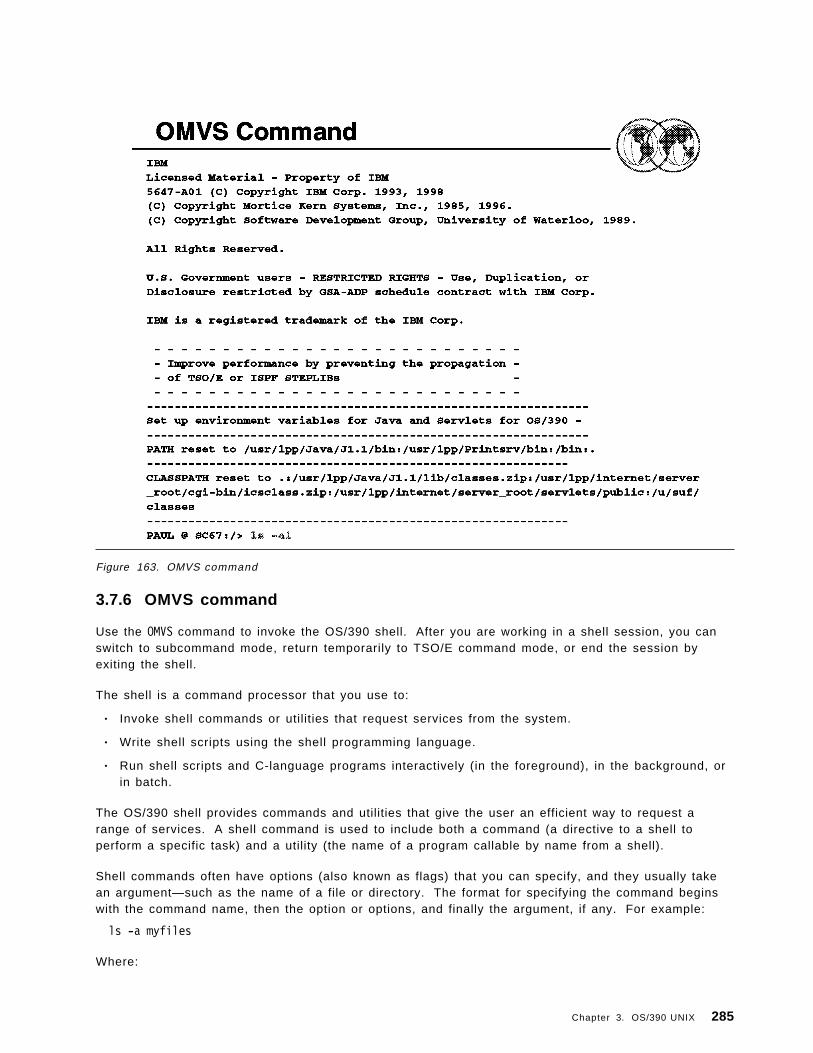
Figure 163. OMVS command
3.7.6 OMVS command
Use the OMVS command to invoke the OS/390 shell. After you are working in a shell session, you canswitch to subcommand mode, return temporarily to TSO/E command mode, or end the session byexiting the shell.
The shell is a command processor that you use to:
• Invoke shell commands or utilities that request services from the system.
• Write shell scripts using the shell programming language.
• Run shell scripts and C-language programs interactively (in the foreground), in the background, orin batch.
The OS/390 shell provides commands and utilities that give the user an efficient way to request arange of services. A shell command is used to include both a command (a directive to a shell toperform a specific task) and a utility (the name of a program callable by name from a shell).
Shell commands often have options (also known as flags) that you can specify, and they usually takean argument—such as the name of a file or directory. The format for specifying the command beginswith the command name, then the option or options, and finally the argument, if any. For example:
ls -a myfiles
Where:
Chapter 3. OS/390 UNIX 285

ls is the command name, -a is the option, and myfiles is the argument.
This visual shows the screen when the OMVS command is issued from ISPF Option 6.
The command line is at the bottom of the screen and the following command is shown:
ls -al
This command lists the files and directories of the user. If the pathname is a file, ls displaysinformation on the file according to the requested options. If it is a directory, ls displays informationon the files and subdirectories therein. You can get information on a directory itself using the -doption.
If you do not specify any options, ls displays only the filenames. When ls sends output to a pipe or afile, it writes one name per line; when it sends output to the terminal, it uses the -C (multicolumn)format.
286 ABCs of OS/390 System Programming

Figure 164. Files in a user ′s root directory
3.7.7 OMVS command results
This visual shows the result of the ls -al command. It displays the files and directories and shows thefile access allowed for the user, the user ′s group, and other users.
Chapter 3. OS/390 UNIX 287

Figure 165. RACF definitions
3.8 RACF definitions
OS/390 UNIX provides security mechanisms that work with the security offered by the OS/390 system.A security product is required.
Before you can install and debug UNIX System Services you need to have access to UNIX SystemServices data sets and members which are named in directories and files.
RACF and also other security related products allow access to our MVS UNIX environment. Thisaccess can be allowed without being a TSO/E user.
If your user ID should have access to MVS UNIX your security administrator has to specify the homedirectory, the shell program, and a UID in the OMVS segment. In addition the security administratorhas to provide a group ID (GID) for any RACF group that the security administrator is connected to. Ifthis is done you should be able to access the UNIX shell or work with the ISPF driven ISHELL. Thedecision whether you will be able to access directories or files will be made by UNIX security.
In addition, your RACF administrator has to provide a user ID that is assigned to the OMVS andBPXOINIT address spaces (started procedure). This user ID needs only to have an OMVS segment andshould be connected to a RACF group with a GID.
288 ABCs of OS/390 System Programming

Figure 166. RACF OMVS segments
3.8.1 RACF OMVS segments
All users and programs that need access to OS/390 UNIX System Services must have a RACF userprofile defined with an OMVS segment which has as a minimum a UID specified. A user without a UIDcannot access OS/390 UNIX. Note that it is possible for multiple users to have the same UID numberspecified. However, this is not recommended.
The RACF user profile has a segment called OMVS for OS/390 UNIX support. A user ID must have anOMVS segment defined in order to use OS/390 UNIX System Services, for example access the ISHELLor the shell. This segment has three fields:
UID A number from 0 to 2147483647 that identifies an OS/390 UNIX user. An OS/390 UNIXuser must have a UID defined.
HOME The name of a directory in the file system. This directory is called the home directoryand becomes the current directory when the user accesses OS/390 UNIX. This field isoptional.
PROGRAM The name of a program. This is the program that will be started for the user when theuser begins an OS/390 UNIX session. Usually this is the program name for the OS/390UNIX shell. This field is optional.
The RACF group also has a segment called OMVS to define OS/390 UNIX groups. It contains only onefield:
GID A number from 0 to 2147483647 which identifies an OS/390 UNIX group.
Chapter 3. OS/390 UNIX 289

The home directory is the current directory when a user invokes OS/390 UNIX. During OS/390 UNIXprocessing this can be changed temporarily by using the cd (change directory) shell command. Thecommand will not change the value in the RACF profile. The directory specified as home directory inthe RACF profile must exist (be pre-allocated) before a user can invoke OS/390 UNIX. If a homedirectory is not specified in RACF, the root (/) directory will be used as default.
The example on the visual shows a user profile for TSO/E user ID SMITH which is connected to twogroups, PROG1 and PROG2. SMITH is defined as an OS/390 UNIX user because the user ID has a UIDspecified. The home directory is /u/smith and user SMITH will get into the shell after issuing the OMVScommand because the name of the shell, /bin/sh is specified as program name.
The program name in the OMVS segment specifies the name of the first program to start when OS/390UNIX is invoked. Usually this is the name of the OS/390 UNIX shell.
290 ABCs of OS/390 System Programming

Figure 167. IEASYSxx parmlib member
3.9 IEASYSxx parmlib member
The initial parmlib settings for the OS/390 UNIX kernel are pointed to by the OMVS parameter in theIEASYSxx parmlib member.
The OMVS parameter in the IEASYSxx parmlib member lets you specify one or more BPXPRMxxparmlib members to be used to specify the initial parmlib settings for the kernel. If you do not specifythe OMVS parameter, or if you specify OMVS=DEFAULT, the kernel is started in a minimumconfiguration mode with all BPXPRMxx parmlib statements taking their default values.
OMVS may also be left out or coded as DEFAULT. This allows the OS/390 UNIX kernel to start in aminimum configuration. All BPXPRMxx values will take their default values and a temporary root filesystem will be set up in memory.
Note: The start and stop commands for the OS/390 UNIX kernel are no longer supported.
Activation of kernel services is available in two modes:
• Minimum mode• Full-function mode
Chapter 3. OS/390 UNIX 291

Figure 168. OS/390 UNIX min imum mode
3.9.1 OS/390 UNIX minimum mode
Minimum mode is intended for installations that do not intend to use OS/390 UNIX System Services, butwhich allows the IPL process to complete. In this mode many services are available to programs.Some that require further customization such as a fork() will fail.
If you do not specify OMVS= in the IEASYSxx parmlib member or if you specify OMVS=DEFAULT,then kernel services start up in minimum mode when the system is IPLed. This mode is intended forinstallations that do not plan to use the kernel services. In minimum mode:
• Many services are available, but some functions such as TCP/IP sockets that require other systemcustomization, may not work.
• TCP/IP sockets (AF_INET) are not available.
• A Temporary File System (TFS) is used. A TFS is an in-storage file system, hence no physicalDASD data set needs to exist or be mounted.
A temporary file system (kept in memory) is created for the root. The required directories (/bin, /etc,/tmp, /dev, and /dev/null) are built. There are no executables in this file system.
292 ABCs of OS/390 System Programming

Figure 169. Minimum mode TFS
3.9.2 Minimum mode TFS
A temporary file system (TFS) is an in-memory file system which delivers high-speed I/O. If the kernelis started in minimum setup mode, the TFS is automatically mounted.
The system is in minimum mode when:
• OMVS=Defaul t
• No OMVS Statement in IEASYSxx (no BPXPRMxx member in the parmlib)
A temporary file system is used as the root file system. The temporary file system is initialized andprimed with a minimum set of files and directories.
Note: Any data written to this file system is not written to DASD.
The temporary file system is initialized with these directories and files:
/ (root directory)/bin directory/etc directory/tmp directory/dev directory/dev/null file
Chapter 3. OS/390 UNIX 293

There are no executables in the temporary file system (that is, you will not find the shell and utilities).Do not attempt to install OS/390 UNIX System Services application services in the TFS, since no datawill be written to DASD.
Because the TFS is a temporary file system, unmounting it causes all data stored in the file system tobe discarded. If, after an unmount, you mount another TFS, that file system has only a dot (.) and adot-dot (..) and nothing else.
294 ABCs of OS/390 System Programming

Figure 170. OS/390 UNIX full-function mode
3.9.3 OS/390 UNIX full-function mode
Full-function mode is started at IPL time when the OMVS parameter in the IEASYSxx parmlib memberpoints to one or more BPXPRMxx parmlib members.
There must be a root HFS built and defined in BPXPRMxx for OMVS to initialize correctly and SMS,WLM, and RACF customization should be completed.
3.9.3.1 BPXPRMnn
BPXPRMnn is a 1-to-8 character name of a started procedure JCL that initializes the OS/390 UNIXkernel. The default is OMVS.
The ROOT statement defines and mounts the root file system. In this example:
• HFS is the TYPE of the file system.• ′OMVS.ROOT′ is the file system which is the name of an already defined PDSE/X data set.• The root file system has a default of read/write mode.
If an active BPXPRMxx parmlib member specifies “FILESYSTEM TYPE(HFS),” then the kernel servicesstart up in full-function mode when the system is IPLed. To use the full function, you need to:
• Set up BPXPRMxx parmlib definitions• Set up DFSMS/MVS• Set up the hierarchical file system/s (HFS)
Chapter 3. OS/390 UNIX 295

• Install UNIX System Services application services• Set up the security product definitions for OS/390 UNIX• Set up the users′ access and their individual file systems
It is also possible to create a sockets-only level of OS/390 UNIX. This requires a BPXPRMxx parmlibmember with only the socket file system defined. A minimal mode configuration with a temporary filesystem will be set up.
DFSMS/MVS manages the hierarchical file system (HFS) data sets that contain the file systems. Touse kernel services in full-function mode, SMS must be active.
3.9.3.2 BPXOINIT
As of OS/390 Release 3, BPXOINIT is the started procedure that runs the initialization process.BPXOINIT is also the jobname of the initialization process. (Prior to OS/390 Release 3, the initializationprocess was created via an APPC allocate and the jobname was OMVSINIT.) BPXOINIT is shipped inSYS1.PROCLIB.
At system IPL time, kernel services are started automatically. If the OMVS parameter in the IEASYSxxparmlib parameter is not specified, the kernel services are started in minimum mode. If the OMVSparameter specifies one or more BPXPRMxx parmlib members, they are all used to configure thekernel services when the system is IPLed.
The BPXOINIT address space has two categories of functions:
1. It behaves as PID(1) of a typical UNIX system. This is the parent of /etc/rc, and it inherits orphanedchildren so that their processes get cleaned up using normal code in the kernel. This task is alsothe parent of any MVS address space that is dubbed and not created by fork or spawn. Therefore,TSO/E commands, batch jobs, and so on have a parent PID of 1.
2. Certain functions that the kernel performs need to be able to make normal kernel calls. Thisaddress space is used for these activities; for example, mmap() and user ID alias processing.
296 ABCs of OS/390 System Programming

Figure 171. OS/390 UNIX installation
3.10 OS/390 UNIX installation
For a full configuration you need to build a complete root file system.
Beginning with OS/390 Version 2 Release 6, ServerPac supplies the jobs, ALLOCDS and RESTORE, todownload the PDS from tape to DASD. The other two jobs, ESTABFS and RESTFS, will copy the twomembers of the “hlq.HFSFILE” to the HFS directory “/RESTORE” and decompress them.
After running these jobs you have a complete root file system containing all the root-level directories,files, and programs.
ServerPac builds the root for you with all the features that you ordered already installed in it. Theyuse the UNIX pax utility to compress the hierarchical format into an HFS file. It is distributed to you asa member of ′hlq.HFSFILE′. Another member of this data set is the pax utility used to build theprevious member.
pax pax reads and writes archive files. An archive file concatenates the contents of files anddirectories, and can also record file modification information such as dates, owner names, andso on. You can therefore use a single archive file to transfer a directory structure from onemachine to another, or to back up or restore groups of files and directories.
hlq.HFSFILE(BACKUP) Backup of Root File System hlq.HFSFILE(PAX) Decompress Utility
In OS/390 V2 R6 the ServerPac job ESTABFS performs the following tasks for you:
Chapter 3. OS/390 UNIX 297

• Unmounts the IPLed ROOT temporary file system
• Creates ROOT HFS
• Mounts the created ROOT HFS to ′ / ′
• Creates ETC HFS
• Creates directory ′ /etc′
• Mounts the created ETC HFS to ′ /etc′
• Creates transient HFS
• Creates directory ′ /RESTORE′
• Mounts the created transient HFS to ′ /RESTORE′
• Updates the BPXPRMFS with the MOUNT FILESYSTYPE section
• Updates the BPXPRMFS with the FILESYSTYPE TYPE(....) and the corresponding entry points
After this job ends successfully, the next job to run is RESTFS. In OS/390 V2 R6 this job will do thefollowing tasks for you:
• Re-mount the transient HFS (ends with RC=12 if already mounted)
• OPUT hlq.HFSFILE(BACKUP) to ′ /RESTORE/backup′ in binary mode
• OPUT hlq.HFSFILE(PAX) to ′ /RESTORE/pax′ in binary mode
• Allocates STDIN, STDOUT, and STDERR files (UNIX standard outputs). Receives an RC=4 if thedirectory is empty
• Unpack the ′ /RESTORE/backup′ file with the ′ /RESTORE/pax′ utility corresponding entry points
• Unlink the allocated file in the directory ′ /RESTORE′
• Unmount transient HFS allocated to the directory ′ /RESTORE′
• Remove the directory ′ /RESTORE′
• Deletes the transient HFS DS
298 ABCs of OS/390 System Programming

Chapter 4. Language Environment
Language Environment provides a common run-time environment for IBM versions of certain high-levellanguages (HLLs), namely, C, C++, COBOL, Fortran, and PL/I, in which you can run existingapplications written in previous versions of these languages as well as in the current LanguageEnvironment-conforming versions. Prior to Language Environment, each of the HLLs had to provide aseparate run-time environment.
Language Environment combines essential and commonly used run-time services, such as routines forrun-time message handling, condition handling, storage management, date and time services, andmath functions, and makes them available through a set of interfaces that are consistent acrossprogramming languages. With Language Environment, you can use one run-time environment for yourapplications, regardless of the application′s programming language or system resource needs becausemost system dependencies have been removed.
Language Environment provides compatible support for existing HLL applications; most existingsingle-language applications can run under Language Environment without being recompiled orrelink-edited. POSIX-conforming C applications can use all Language Environment services.
Copyright IBM Corp. 2000 299

Figure 172. Language Environment (LE)
4.1 Language Environment (LE)
Today, enterprises need efficient, consistent, and less complex ways to develop quality applicationsand to maintain their existing inventory of applications. The trend in application development is tomodularize and share code. Language Environment gives you a common environment for allLanguage Environment-conforming high-level language (HLL) products. An HLL is a programminglanguage above the level of assembler language and below that of program generators and querylanguages.
In the past, programming languages also have had limited ability to call each other and behaveconsistently across different operating systems. This has constrained those who wanted to use severallanguages in an application. Programming languages have had different rules for implementing datastructures and condition handling, and for interfacing with system services and library routines.
The visual describes the topics to be discussed in this chapter.
300 ABCs of OS/390 System Programming

Figure 173. HLL concepts and LE
4.1.1 HLL concepts and LE
An HLL is implemented through a compiler code that translates the HLL statements in object code.This object code is the fabric of the executable program, also called the “load module” or “programobject.” It has instructions recognized by the processor of the specific platform where it is supposedto be executed. The object code is included (in the load module) at three different times in OS/390:
• At compile time
• At linkage editor time, through the INCLUDE statement or resolving external references from theSYSLIB library
• At execution time, through MVS dynamic link macros such as LINK and LOAD, which fetch tomemory, code from the load modules library. This approach is also called “late binding.”
The libraries containing the code invoked dynamically are called the run-time environment.
Language Environment establishes a common run-time environment plus a common set of the SYSLIBlibraries for all participating HLLs. However, due to many language-specific functions, there is still aneed of some language specific libraries as C/C++, COBOL, FORTRAN, PL/I. Language Environmentcombines essential run-time services, such as routines for run-time message handling, conditionhandling, and storage management. All of these services are available through a set of interfaces thatare consistent across programming languages. You may either call these interfaces yourself, or uselanguage-specific services that call the interfaces. With Language Environment, you can use onerun-time environment for your applications, regardless of the application programming language orsystem resource needs.
Chapter 4. Languge Environment 301

Figure 174. LE components
4.1.2 LE componentsThe visual shows the separate components that make up Language Environment.
Language Environment consists of:
• Basic routines that support starting and stopping programs, allocating storage, communicating withprograms written in different languages, and indicating and handling conditions
• Common library services, such as math services and date and time services, that are commonlyneeded by programs running on the system. These functions are supported through a library ofcallable services.
• Language-specific portions of the run-time library, because many language-specific routines callLanguage Environment services. However, behavior is consistent across languages.
POSIX support is provided in the Language Environment base and in the C language-specific library.
302 ABCs of OS/390 System Programming

Figure 175. LE
4.1.3 LE′s common run-time environment
The graphic illustrates the common environment that Language Environment creates. It also showsthat each HLL has its specific run-time and SYSLIB libraries, and shares with others HLLs a CommonExecution Library (CEL). The graphic further shows that the load modules produced in such way canbe executed in different operating environments under OS/390 or VM/ESA.
4.1.3.1 Using Language Environment
Language Environment helps you create mixed-language applications and gives you a consistentmethod of accessing common, frequently used services. Building mixed-language applications iseasier with Language Environment-conforming routines because Language Environment establishes aconsistent environment for all languages in the application.
Language Environment provides the base for future IBM language library enhancements in the OS/390and VM environments. Many system dependencies have been removed from LanguageEnvironment-conforming language products.
Because Language Environment provides a common library, with services that you can call through acommon callable interface, the behavior of your applications will be easier to predict. LanguageEnvironment′s common library includes common services such as messages, date and time functions,math functions, application utilities, system services, and subsystem support.
The following example illustrates how to invoke a Language Environment service in COBOL for OS/390:
Chapter 4. Languge Environment 303

ALL ″CEESSSQT″ using argument, feedback-code, result
You should use a CALL statement with the correct parameters for that particular service.
The language-specific portions of Language Environment provide language interfaces and specificservices that are supported for each individual language. Language Environment is accessed throughdefined common calling conventions.
304 ABCs of OS/390 System Programming

Figure 176. HLLs demanding LE
4.1.4 HLLs demanding LE
OS/390 Language Environment for OS/390 & VM is the prerequisite run-time environment forapplications generated with the following IBM compiler products:
• OS/390 C /C++
• IBM C for VM/ESA
• C/C++ Compi ler for MVS/ESA
• AD/Cycle C/370 Compiler
• VisualAge for Java, Enterprise Edition for OS/390
• COBOL for OS/390 & VM
• COBOL for MVS & VM
• PL/I for MVS & VM (formerly AD/Cycle PL/I for MVS & VM)
• VS FORTRAN and FORTRAN IV (in compatibility mode)
Language Environment supports, but is not required for, VS FORTRAN Version 2 compiled code(OS/390 only).
In many cases, you can run compiled code generated from the previous versions of the abovecompilers. A set of assembler macros is also provided to allow assembler routines to run withLanguage Environment.
Chapter 4. Languge Environment 305

For more information on IBM VisualAge for Java, Enterprise Edition for OS/390, refer to the productdocumentation.
306 ABCs of OS/390 System Programming
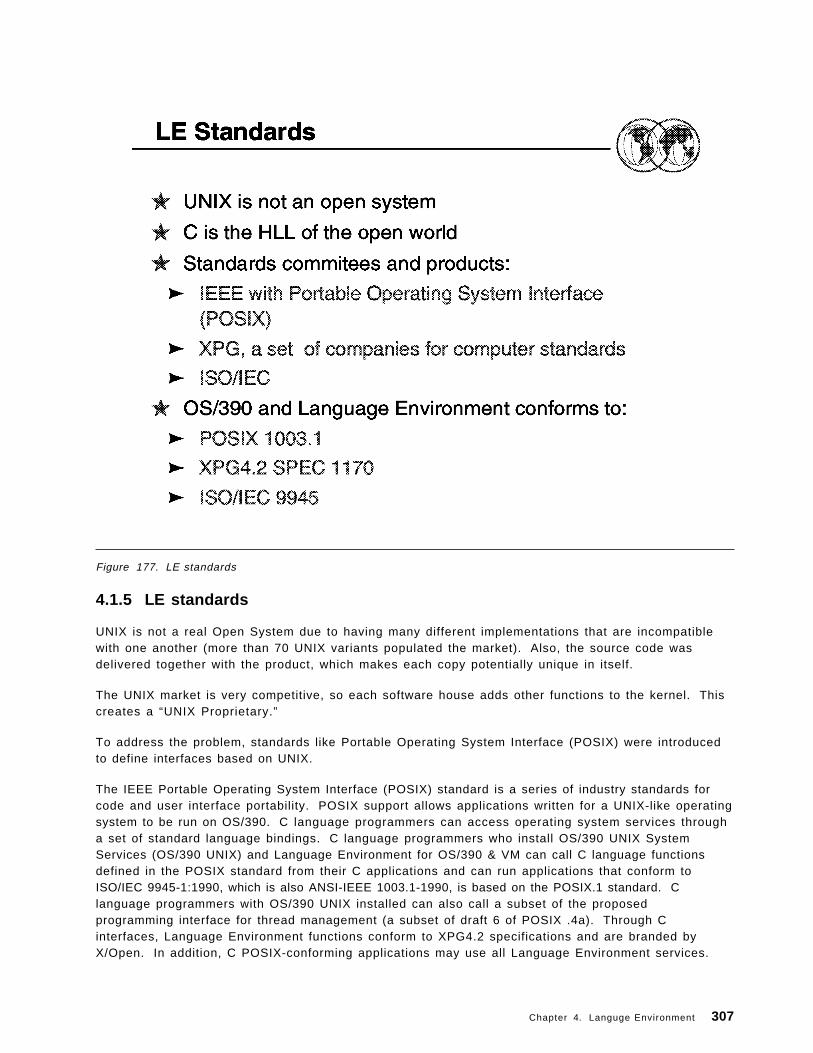
Figure 177. LE standards
4.1.5 LE standards
UNIX is not a real Open System due to having many different implementations that are incompatiblewith one another (more than 70 UNIX variants populated the market). Also, the source code wasdelivered together with the product, which makes each copy potentially unique in itself.
The UNIX market is very competitive, so each software house adds other functions to the kernel. Thiscreates a “UNIX Proprietary.”
To address the problem, standards like Portable Operating System Interface (POSIX) were introducedto define interfaces based on UNIX.
The IEEE Portable Operating System Interface (POSIX) standard is a series of industry standards forcode and user interface portability. POSIX support allows applications written for a UNIX-like operatingsystem to be run on OS/390. C language programmers can access operating system services througha set of standard language bindings. C language programmers who install OS/390 UNIX SystemServices (OS/390 UNIX) and Language Environment for OS/390 & VM can call C language functionsdefined in the POSIX standard from their C applications and can run applications that conform toISO/IEC 9945-1:1990, which is also ANSI-IEEE 1003.1-1990, is based on the POSIX.1 standard. Clanguage programmers with OS/390 UNIX installed can also call a subset of the proposedprogramming interface for thread management (a subset of draft 6 of POSIX .4a). Through Cinterfaces, Language Environment functions conform to XPG4.2 specifications and are branded byX/Open. In addition, C POSIX-conforming applications may use all Language Environment services.
Chapter 4. Languge Environment 307

Figure 178. LE terms and HLL equivalents
4.1.6 LE terms and HLL equivalentsThe Language Environment program management model provides a framework within which anapplication runs. It is the foundation of all of the component models--condition handling, run-timemessage handling, and storage management--that comprise the Language Environment architecture.The program management model defines the effects of programming language semantics inmixed-language applications and integrates transaction processing and multithreading.
Some terms used to describe the program management model are common programming terms; otherterms are described differently in other languages. It is important that you understand the meaning ofthe terminology in a Language Environment context as compared to other contexts.
4.1.6.1 General programming terms
• Application program
A collection of one or more programs cooperating to achieve particular objectives such asinventory control or payroll.
• Environment
In Language Environment, normally a reference to the run-time environment of HLL the enclavelevel.
308 ABCs of OS/390 System Programming

4.1.6.2 LE terms and HLL equivalents:
• Routine
In Language Environment, refers to a procedure, or a function, or a subroutine.
Equivalent HLL terms: COBOL--program; C/C++--function; PL/I--procedure, BEGIN block.
• Enclave
The enclave defines the scope of HLL semantics. In Language Environment, it means a collectionof routines, one of which is named as the main routine. The enclave contains at least one thread.
Equivalent HLL terms: COBOL--run unit, C/C++--program, consisting of a main C function and itssub-functions, PL/I--main procedure and its subroutines, and FORTRAN--program and itssubroutines.
• Process
The highest level of the Language Environment program management model. A process is acollection of resources, both program code and data, and consists of at least one enclave.
• Thread
An execution construct that consists of synchronous invocations and terminations of routines. Thethread is the basic run-time path within the Language Environment program management model,and is dispatched by the system with its own run-time stack, instruction counter, and registers.Threads may exist concurrently with other threads.
Terminology for Data:
• Automatic data
Data that does not persist across calls. It is allocated with the same value on entry and reentryinto a routine.
• External data
Data that can be referenced by multiple routines and data areas. External data is knownthroughout an enclave.
• Local data
Data that is known only to the routine in which it is declared.
Equivalent HLL terms: C/C++--local data, COBOL--WORKING-STORAGE data items andLOCAL-STORAGE data items, PL/I--data declared with the PL/I INTERNAL attribute.
Chapter 4. Languge Environment 309

Figure 179. LE program management
4.1.7 LE program management
Three entities-- process, enclave, and thread--are at the core of the Language Environment programmanagement model.
The visual shows the relationship between processes, enclaves, and threads. It illustrates the simplestform of the Language Environment program management model and how resources such as storageare managed.
4.1.7.1 ProcessThe highest level component of the Language Environment program model is the process. A processconsists of at least one enclave and is logically separate from other processes. Processes do notshare storage and are independent of and equal to each other; they are not hierarchically related.
Language Environment generally does not allow language file sharing across enclaves nor does itprovide the ability to access collections of externally stored data. However, the PL/I standardSYSPRINT file may be shared across enclaves. The Language Environment message file also may beshared across enclaves, since it is managed at the process level. The Language Environmentmessage file contains messages from all routines running within a process, making it a useful centrallocation for messages generated during run time.
Processes can create new processes and communicate to each other by using LanguageEnvironment-defined communication, for such things as indicating when a created process has beenterminated.
310 ABCs of OS/390 System Programming

4.1.7.2 Enclaves
A key feature of the program management model is the enclave, a collection of the routines that makeup an application. As mentioned in the terminology previously defined, the enclave is the equivalent ofany of the following:
• A run unit, in COBOL
• A program, consisting of a main C function and its sub-functions, in C
• A main procedure and all of its subroutines, in PL/I
• A program and its subroutines, in FORTRAN
The enclave consists of one main routine and zero or more subroutines. The main routine is the firstto execute in an enclave; all subsequent routines are named as subroutines.
4.1.7.3 Threads
Each enclave consists of at least one thread, the basic instance of a particular routine. A thread iscreated during enclave initialization with its own run-time stack, which keeps track of the thread′sexecution, as well as a unique instruction counter, registers, and condition-handling mechanisms.Each thread represents an independent instance of a routine running under an enclave′s resources.
Threads share all of the resources of an enclave. A thread can address all storage within an enclave.All threads are equal and independent of one another and are not related hierarchically. A thread cancreate a new enclave. Because threads operate with unique run-time stacks, they can runconcurrently within an enclave and allocate and free their own storage. Because they may executeconcurrently, threads can be used to implement parallel processing applications and event-drivenapplications.
The figure illustrates the full Language Environment program model, with its multiple processes,enclaves, and threads.
It shows each process is within its own address space. An enclave consists of one main routine, withany number of subroutines. A main routine might not be active at all times in a POSIX application, ifthe thread in which the main routine executes terminates before the other threads that it created.
External data is available only within the enclave where it resides; notice that even though the externaldata may have identical names in different enclaves, the external data is unique to the enclave. Thescope of external data, as described earlier, is the enclave. The threads can create enclaves, whichcan create more threads, and so on.
Chapter 4. Languge Environment 311

Figure 180. Assembler language and programs
4.1.8 Assembler language and programsA computer can understand and interpret only machine language. Machine language is in binary formand, thus, is very difficult to write. The assembler language is a symbolic programming language thatyou can use to code instructions instead of coding in machine language.
Because the assembler language lets you use meaningful symbols made up of alphabetic and numericcharacters, instead of just the binary digits 0 and 1 used in machine language, you can make yourcoding easier to read, understand, and change. Assembler is also enriched by a huge set of macrosthat make it a very powerful language; however, its major quality is the performance of its object codeat running time.
One of the most key aspects of a language is its readability and and capacity to document itself.However, certain modern languages like C do not follow this rule. Then, we may say that if you writean assembler program using all the documenting capability of its features, chances are that you mayhave a more readable code than a HLL.
The Assembler must translate the symbolic assembler language into machine language before thecomputer can run your program. The specific procedures followed to do this may vary according tothe system you are using. However, the method is basically the same for all systems and consists ofthe following:
Your program, written in the assembler language, becomes the source module that is input to theAssembler. The Assembler processes your source module and produces an object module in machinelanguage (called object code). The object module can be used as input to be processed by the linkage
312 ABCs of OS/390 System Programming

editor or the binder. The linkage editor or binder produces a load module that can be loaded later intothe main storage of the computer. When your program is loaded, it can then be run. Your sourcemodule and the object code produced are printed, along with other information, on a program listing.
4.1.8.1 Assembler languageThe assembler language is the symbolic programming language that lies closest to the machinelanguage in form and content. You will, therefore, find the assembler language useful when:
• You need to control your program closely, down to the byte level and even to the bit level.
• You must write subroutines for functions that are not provided by other symbolic programminglanguages, such as COBOL, FORTRAN, or PL/I.
• You need good performance at execution time.
The assembler language is made up of statements that represent either instructions or comments.The instruction statements are the working part of the language and are divided into the followingthree groups:
• Machine instructions
A machine instruction is the symbolic representation of a machine language instruction. It iscalled a machine instruction because the Assembler translates it into the machine language codethat the computer can run.
• Assembler instructions
An assembler instruction is a request to the Assembler to do certain operations during theassembly of a source module; for example, defining data constants, reserving storage areas, anddefining the end of the source module. Except for the instructions that define constants, and theinstruction used to generate no-operation instructions for alignment, the Assembler does nottranslate assembler instructions into object code.
• Macro instructions
A macro instruction is a request to the Assembler program to process a predefined sequence ofinstructions called a macro definition. From this definition, the Assembler generates machine andassembler instructions, which it then processes as if they were part of the original input in thesource module.
IBM supplies macro definitions for input/output, data management, and supervisor operations thatyou can call for processing by coding the required macro instruction.
You can also prepare your own macro definitions, and call them by coding the correspondingmacro instructions. Rather than code all of this sequence each time it is needed, you can create amacro instruction to represent the sequence and then, each time the sequence is needed, simplycode the macro instruction statement. During assembly, the sequence of instructions representedby the macro instruction is inserted into the source program.
4.1.8.2 Assembler program relationship to OS/390The Assembler program, also referred to as the Assembler, processes: the machine, assemblerinstructions, and macro instructions you have coded (source statements) in the assembler language,and produces an object module in machine language.
The High Level Assembler operates under the OS/390 operating system. This operating systemprovides the Assembler with services for:
• Assembling a source module
• Running the assembled object module as a program
In writing a source module, you must include instructions that request any required service functionsfrom the operating system. OS/390 provides the following services:
Chapter 4. Languge Environment 313

• For assembling the source module:
− A control program− Sequential data sets to contain source code− Libraries to contain source code and macro definitions− Utilities
• For preparing for the execution of the Assembler program as represented by the object module:
− A control program− Storage allocation− Input and output facilities
It can be very difficult to write an assembler language program using only machine instructions. TheAssembler provides additional functions, not discussed here, that make this task easier.
314 ABCs of OS/390 System Programming

Figure 181. Sample assembler routine
4.1.9 Sample assembler routine
This visual shows a simple main assembler routine (source code) that brings up the environment,returns with a return code of 0, modifier of 0, and prints a message in the main routine.
Chapter 4. Languge Environment 315

316 ABCs of OS/390 System Programming

Chapter 5. Infoprint Server
Infoprint Server is an optional feature of OS/390 Version 2 Release 8 that uses OS/390 UNIX SystemServices. This feature is the basis for a total print serving solution for the OS/390 environment. It letsyou consolidate your print workload from many servers onto a central OS/390 print server
Note: Beginning with OS/390 Version 2 Release 5, this product was called OS/390 Print Server.
Infoprint Server delivers improved efficiency and lower overall printing cost with the flexibility forhigh-volume, high-speed printing from anywhere in the network. With Infoprint Server, you can reducethe overall cost of printing while improving manageability, data retrievability, and usability.
The IP PrintWay/NetSpool feature available in OS/390 Version 1 Release 3 and Version 2 Release 4 isnow a part of Infoprint Server. IP PrintWay allows you fast and reliable access to Transmission ControlProtocol/Internet Protocol (TCP/IP)-connected printers. NetSpool automatically directs VirtualTelecommunications Access Method (VTAM) application data to the job entry subsystem (JES) spoolwithout requiring application changes.
Copyright IBM Corp. 2000 317

Figure 182. OS/390 Print Server components
5.1 OS/390 Print Server
With the introduction of the OS/390 Print Server, a new optional feature of OS/390 Release 5, usershave the opportunity to consolidate their print workload on OS/390. This new function allows access tofast and reliable AFP printers, or TCP/IP-connected printers from OS/390, including UNIX services andLAN clients. Users can define their printers in a central repository, allowing clients in the network touse any printer in the enterprise that is registered to the OS/390 Print Server.
The OS/390 Print Server is the framework for a total print serving solution for the OS/390 systemenvironment. It extends the functions provided by the optional IP PrintWay and NetSpool features inOS/390 Version 1 Release 3 and OS/390 Version 2 Release 4. IP PrintWay and NetSpool are now partof the OS/390 Print Server.
With the addition of a new Print Interface component, the OS/390 Print Server provides an end-to-endintegrated solution from print submission to the printer. The IBM OS/390 Print Server consists of threecomponents, as shown in the visual.
• OS/390 Print Interface
The OS/390 Print Interface is the central server element of the IBM OS/390 Print Server. It consistsof an LPD that allocates data sets on the JES spool using information from the printer definitions inthe printer inventory.
The OS/390 Print Interface address space, shown in the visual, runs as an LPD on the OS/390system. It provides the following functions:
318 ABCs of OS/390 System Programming

− It receives print requests and dynamically allocates a data set on the JES spool for each dataset to be printed.
− It responds to query requests and returns the status of the data set on the JES spool or a list ofprinter names, locations, and descriptions.
− It removes data sets from the JES spool that have not been selected for printing.
The OS/390 Print Interface receives print requests that are submitted using TCP/IP protocol from:
− Remote systems in the TCP/IP LAN network− OS/390 UNIX System Services (OpenEdition)− A Windows 95 or Windows NT system− A local OS/390 system
• IP PrintWay
IP PrintWay can use standard LPR/LPD or direct socket printing protocol to route JES2 or JES3print data from OS/390 to another system′s spool or to a printer in the TCP/IP network. Dependingupon selected options, the print data is sent as is (binary format), or translated from EBCDIC intoASCII for the target system or printer. IP PrintWay is better than the TCP/IP Network Print Facility(NPF) for MVS in usability, performance, capacity and function, and is the strategic replacement forNPF.
• NetSpool
NetSpool allows the user to automatically reroute VTAM application output (such as from CICS orIMS) to the JES spool without requiring application program changes. Application output can thenbe printed to any server or printer that is connected to the TCP/IP network using IP PrintWay, or toan AFP printer using Print Services Facility (PSF)/MVS.
Note: This component of the IBM OS/390 Print Server is optional.
The following operating systems, shown in the visual, can use the LPR command to send printrequests to the Print Interface:
• AIX 4.1.4 or 4.2.X• OS/2• VM/CMS• HPUX• Win 3.1
Chapter 5. Infoprint Server 319

Figure 183. TCP/IP Print Protocol
5.1.1 TCP/IP Print Protocol
TCP/IP provides client and server support for remote printing by supporting the following commands:
LPR Line print requestor (LPR) is the command that requests printing. The standard LPR commandhas attributes such as file name, IP address, and queue name. The LPR command sends printdata to an LPD.
LPD Line print daemon (LPD) is like a destination. An LPD daemon waits for the LPR command tobe invoked. The LPD daemon receives the print data and sends it to a print queue. It canreside in the software or in the printer hardware, as shown in the visual.
The LPR command and the LPD function are part of IBM TCP/IP of the OS/390 base feature.
You can print from the following environments by using the TCP/IP LPR command:
• AIX 4.1.4 or 4.2.x• OS/2• VM/CMS• A remote OS/390 system using TSO/E• A local OS/390 system using TSO/E
320 ABCs of OS/390 System Programming

Figure 184. Components of OS/390 Print Server
5.1.2 Components of OS/390 Print Server
The OS/390 Print Server consists of three major components in OS/390 Releases 5, 6, and 7. They areas follows:
• Print Interface
The Print Interface component of Infoprint Server runs on the OS/390 system. It provides an LPDthat receives print requests from remote workstations that have TCP/IP access and from theOS/390 UNIX System Services shell printing commands on the local OS/390 system.
• NetSpool
NetSpool intercepts print data from VTAM applications, such as CICS and IMS. NetSpool convertsthe data into S/390 line data and creates output data sets on the JES2 or JES3 spool. JES or PSFfor OS/390 can print the output data sets or transmit them to another location for printing.Alternatively, IP PrintWay can transmit the data sets to a remote printer in your TCP/IP network.
• IP PrintWay
IP PrintWay transmits output data sets from JES2 or JES3 to remote printers or to host systems inyour TCP/IP network. A print server can be running on the host system. The remote printer orhost system must support either the LPR/LPD protocol, the IPP protocol, or direct socket printing
Chapter 5. Infoprint Server 321

Figure 185. Infoprint Server overview
5.2 Infoprint Server overview
Infoprint Server for OS/390, an optional element of OS/390 Version 2 Release 8, provides support forLAN and host printing on OS/390. Infoprint Server consists of several components that work togetherto provide printing services. The visual shows some of the components and how they fit into yoursystem. The components and features of Infoprint Server are shaded in the figure and are as follows:
• Printer Inventory and Printer Inventory Manager
The Printer Inventory Manager controls the Printer Inventory, a set of files in the hierarchical filesystem (HFS) that contain information about each printer to which NetSpool, Print Interface, and IPPrintWay can print. The Printer Inventory also contains system configuration information for IPPrintWay and, optionally, for PSF for OS/390.
• Infoprint Server Windows client
The Windows client provides (1) an AFP printer driver, (2) an AFP viewer plug-in, and (3) an OS/390printer port monitor that sends print requests to the Print Interface component.
• Print Interface
Print Interface processes print requests from remote clients that use any of the following TCP/IPprinting protocols:
− Line printer requester (LPR) to line printer daemon (LPD)− Internet Printing Protocol (IPP)
322 ABCs of OS/390 System Programming

Print Interface also provides OS/390 UNIX shell commands (lp, lpstat, and cancel) and theAOPPRINT JCL procedure to let local users submit print requests to Print Interface.
Print Interface accepts any data format the target printer can print, converts data to EBCDIC orASCII as required by the target printer, and allocates output data sets on the JES spool. PrintInterface can also transform PCL, PDF, PostScript, and SAP data to AFP format prior to writing datato the JES spool, for printing on IBM AFP printers.
• Infoprint Server Transforms for OS/390 and the Transform Manager
Infoprint Server Transforms for OS/390 is a Licensed Program Product (5697-F51) that providesPCL, PostScript, PDF, and SAP to AFP transforms for the OS/390 system. The Transform Managercomponent of Infoprint Server manages the PCL, PostScript, and PDF transforms.
Infoprint Server Transforms also provides OS/390 UNIX shell commands (pcl2afp, ps2afp and itsalias pdf2afp, and sap2afp) to let local users transform data without printing it.
• NetSpool NetSpool processes print requests from VTAM applications, such as CICS and IMS.NetSpool accepts SCS, 3270, and binary data and allocates output data sets on the JES spool.
• IP PrintWay IP PrintWay transmits data sets from the JES spool to printers or print servers usingany of the following TCP/IP protocols:
− Line printer requester (LPR) to line printer daemon (LPD)− Internet Printing Protocol (IPP)− Direct socket printing
• Simple Network Management Protocol (SNMP) subagent
The SNMP subagent lets you use an SNMP manager to view printer characteristics and printerstatus for printers controlled by PSF for OS/390 that do not have internal SNMP agents or are notTCP/IP-attached to PSF.
Chapter 5. Infoprint Server 323

Figure 186. OS/390 Infoprint Server benefits
5.2.1 OS/390 Infoprint Server benefits
In today′s network environments, printers are often attached to a single workstation or are onlyavailable to users of a LAN. Infoprint Server lets you define all of your printers in a centralizedrepository. Any user in the network can send print jobs from OS/390 and LAN clients to any print thatis defined to Infoprint Server. Because all components of Infoprint Server and PSF share the printerdefinitions, you only have to configure each printer in one place.
Because print jobs are managed by the OS/390 JES spool, they are secure and recoverable. OS/390accounting information for print jobs is logged automatically.
The Print Interface automatically detects the data stream for jobs that LAN and OS/390 UNIX SystemServices clients submit. It can then ensure that the selected printer can print the data stream, thussaving paper and time.
Infoprint Server provides support for the most commonly used printer languages in the industry,including Postscript, PCL, and AFP or Mixed Object Document Content Architecture-Presentation(MO:DCA-P). With the optional Infoprint Server Transforms, Infoprint Server also supports PDF SAPOTF, and SAP ABAP. Infoprint Server protects your investment in printer hardware, while providingyou with printing enhancements.
Users of network printing solutions today spend unnecessary time going to the printer to see if theirjobs have printed. If they do not find them immediately, they may resubmit the jobs several timeswithout knowing why they haven′ t printed. With Infoprint Server, users in the LAN and UNIX System
324 ABCs of OS/390 System Programming

Services environments can query the status of their print jobs to find out if a job is processing or iscomplete. Local system users can simply wait for the server to notify them that the job is complete.The users save time, and the business saves paper.
Because of its capabilities for automatic resource management, error recovery, integrated accounting,and printing from 10 to over 1000 pages per minute without application changes, AFP offers anoutstanding solution for high-speed printing. Infoprint Server provides an AFP Printer Driver forWindows 95 and Windows 98 and an AFP Printer Driver for Windows NT and Windows 2000. Therefore,you can print output from any Windows application, such as Lotus WordPro or Freelance, on any ofIBM ′s AFP printers.
Many OS/390 applications generate documents that are formatted for AFP/Intelligent Printer DataStream IPDS printers. You may need to view those documents in an archival system or on a Webserver from your desktop. Infoprint Server includes an AFP Viewer plug-in for the Netscape Navigatorand Microsoft Internet Explorer Web browsers so you can view AFP documents from your Webbrowser. You can also use Infoprint Server to print documents that you are viewing from a Webbrowser to any defined printer.
Chapter 5. Infoprint Server 325

Figure 187. Print Interface
5.2.2 Print Interface
Print Interface runs as a UNIX application that uses the services of OS/390 UNIX System Services.Users can submit print requests from remote clients that use one of the following TCP/IP protocols:
• LPR to LPD. The OS/390 Printer Port Monitor for Windows and commands, such as lpr and lpq,use this protocol.
• Internet Printing Protocol (IPP) beginning with OS/390 Release 8.
Users can submit print requests from the local system with one of the following methods:
• OS/390 UNIX shell printing commands (lp, lpstat, and cancel). These commands, which adhere tothe XPG4.2 standard, let users print HFS files and traditional data sets, query the status of a printjob, and cancel a print job.
• The AOPPRINT JCL procedure, which lets users print HFS files and traditional data sets beginningwith OS/390 Release 8.
The Print Interface performs these functions:
• It creates an output data set on the JES spool for each document to be printed. The Print Interfacemaps the printing options specified on lp commands and some of the printing options specified onlpr commands to JES output parameters. These parameters are the same parameters that you canspecify on JCL statements when you submit batch jobs.
• It responds to query requests with the status of the output data set on the JES spool or a list of theprinters known to the Print Interface.
326 ABCs of OS/390 System Programming

• It removes data sets from the JES spool. The data sets must not yet have been selected forprinting.
The Print Interface performs these functions:
• Printing of any data format that the printer supports
The Print Interface allows users to submit print requests with any data format that the printersupports. These formats include, but are not limited to, PCL, PostScript, MO:DCA-P, S/390 line data,and text.
• The Print Interface detects the data format.
• Validation of print requests
Before accepting print requests, the Print Interface validates, with some exceptions, that adocument can print as requested on the selected printer. For example, the Print Interface rejects adocument with a data format that the printer does not support.
• Notification of completion
The Print Interface notifies users on the local OS/390 system when processing of a document iscomplete.
• Identification of printed output
The Print Interface maintains the user ID of the job submitter for printing on separator pages. BothPSF for OS/390 and IP PrintWay allow installations to write an exit to print separator pages.
• Double-byte character set (DBCS) support
The Print Interface converts DBCS data from one code page to another before writing the data tothe JES spool.
Chapter 5. Infoprint Server 327

Figure 188. NetSpool
5.2.3 NetSpool
The visual shows the steps that occur from the time VTAM applications send print requests to NetSpoolprinter logical units (LUs) until NetSpool allocates output data sets on the JES spool. Each step is asfollows:
1. VTAM applications, such as CICS or IMS, establish communication sessions with NetSpool printerlogical units (LUs) instead of with SNA-network printers. Each NetSpool printer LU must be definedto VTAM as an application logical-unit (LU). NetSpool can process the following types of VTAMdata streams:
• SNA character string (SCS) data over an LU type 1 session• 3270 data over an LU type 3 or LU type 0 session• A binary data stream over an LU type 0, type 1, or type 3 session
2. NetSpool runs as a VTAM application on the same or different OS/390 system. Multiple instancesof NetSpool can run simultaneously in separate address spaces; each instance of NetSpool canprocess VTAM print requests sent to different NetSpool printer LUs.
3. Each NetSpool printer LU must be defined in a printer definition in the Printer Inventory. NetSpoolconverts the data stream into S/390 line-data format and groups the data into output data setsusing information in the printer definition.
4. NetSpool dynamically allocates output data sets on the JES2 or JES3 spool using JES allocationparameters specified in the printer definition, including:
328 ABCs of OS/390 System Programming

• JES work-selection parameters, such as class, forms name, and destination. Theseparameters cause JES to direct the output data sets to the correct JES output writer orfunctional subsystem application (FSA), such as PSF for OS/390 or IP PrintWay.
• Advanced Function Presentation (AFP) parameters, such as the name of a form definition andpage definition. PSF for OS/390 uses these parameters when printing data on IBM AFPprinters.
• Distribution information, such as name and address, which can be printed on output headerpages
Chapter 5. Infoprint Server 329

Figure 189. IP PrintWay
5.2.4 IP PrintWay
IP PrintWay transmits output data sets from the JES spool to printers or print servers in a TCP/IPnetwork using one of the following TCP/IP protocols: LPR to LPD, IPP, or direct-socket printing.
The visual shows the steps that occur from the time IP PrintWay selects output data sets from the JESspool until IP PrintWay transmits the data sets to the target printer or print server and deletes the datasets fro the JES spool. An explanation of each step follows:
1. IP PrintWay selects output data sets from the JES spool according to the JES work-selectionparameters defined for the IP PrintWay FSA. For example, IP PrintWay might select all data sets inJES output class J.
IP PrintWay can select data sets that were allocated on the JES spool by NetSpool or PrintInterface, or submitted from TSO or batch applications. The data sets can contain S/390 line data.ASCII text data, or formatted data, such as PCL, PostScript, SAP, or MO:DCA-P (AFP) data.
2. IP PrintWay runs as a functional subsystem application (FSA) of JES2 or JES3. Several IP PrintWayFSAs can run in one functional subsystem address space (FSS) to handle a high volume of data;however, one PrintWay FSA can transmit data sets to multiple printers or print servers.
3. IP PrintWay uses information in the printer definition in the Printer Inventory to process data sets,select the TCP/IP transmission protocol (LPR, IPP, or direct sockets), and obtain the address of thetarget printer. IP PrintWay can also use the IP address of a target printer specified directly on theOUTPUT JCL statement.
330 ABCs of OS/390 System Programming

IP PrintWay recognizes data sets allocated on the JES spool by Print Interface and does notconvert data from ASCII to EBCDIC or format the data; this is because Print Interface has alreadyconverted data to ASCII if necessary. For other data sets, IP PrintWay can convert data fromEBCDIC to ASCII, can add a header to each page, and can format data using the carriage-controlcharacters in S/390 line data, an FCB, or pagination attributes specified in the printer definition.
4. IP PrintWay maintains a transmission queue to keep track of data sets being processed. Thistransmission queue contains the status of each transmission, routing information, and so on.Using Infoprint Server ISPF panels, the system operator can monitor the status of transmissions,reroute data sets to another print queue or port, and change the transmission options.
5. IP PrintWay can use the LPR to LPD, IPP, or direct-socket TCP/IP protocol to transmit data sets toremote printers or print servers. IP PrintWay also transmits LPD options and IPP job attributes tothe target LPDs and IPP servers. For example, IP PrintWay can transmit information for the LPD toprint on a separator page.
Chapter 5. Infoprint Server 331

Figure 190. Windows 95 and Windows NT support
5.2.5 Windows 95 and Windows NT support
A job submitter can print documents from any Windows application using:
• Standard methods of print submission available with Windows applications
• A Windows (NT or 95) client provided with an IBM OS/390 Print Server
The job submitter′s destination printer can be defined in the OS/390 Printer Inventory.
The Windows client passes job and document attributes to the OS/390 Print Interface. The job name,owner, and the requested printer name are passed to the server.
Note: The OS/390 Print Interface does not return error messages or other job process notifications tothese clients. In addition, Windows clients cannot query the status of print requests or cancel a printrequest.
Note: The OS/390 Print Server Port Monitor must be installed.
332 ABCs of OS/390 System Programming

5.2.5.1 Windows clients
The Infoprint Server Windows clients are as follows:
• AFP Printer Driver for Windows
The AFP Printer Driver creates output files in AFP format, so that users can print documents to IBMAFP printers. The AFP Printer Driver can create output files containing documents, overlays, orpage segments. It can also create inline form definitions for printing documents with specialoptions, such as printing on both sides of the paper.
• AFP Viewer Plug-in for Windows
The AFP Viewer plug-in lets users view documents in AFP format, for example documentsdownloaded from the OS/390 system or documents on the Web. The AFP Viewer plug-in also letsusers print AFP documents to AFP as well as non-AFP printers.
• OS/390 Printer Port Monitor for Windows
The OS/390 Printer Port Monitor lets users print documents using standard print-submissionmethods from any Windows application that supports printing. After the OS/390 Printer PortMonitor is installed and configured on the Windows system, the Port Monitor automatically sendsdocuments to the Print Interface component of Infoprint Server.
5.2.5.2 Requirements for using the IBM-supplied clients
The IBM-supplied AFP clients require Windows 95 or Windows NT (Version 3.51 or later).
The OS/390 Print Server Port Monitor requires that Microsoft TCP/IP protocol be configured andoperational.
The IBM AFP Plug-In Viewer requires Netscape Navigator (Version 3.01 or later) or Microsoft InternetExplorer (Version 3.01, Level 4.70.1215 or later).
The OS/390 Print Server Clients for Windows 95 and Windows NT can be downloaded from the OS/390host. They are located and stored on OS/390 as self-extracting files in directory:
/usr/lpp/Printsrv/win/en_US/
Alternatively, you can download the latest software from the Web using the following site:
http://www.ibm.com/printers
Chapter 5. Infoprint Server 333

Figure 191. OS/390 UNIX System Services
5.2.6 OS/390 UNIX System Services
The Print Interface provides printing support for users and application programs in the OS/390 UNIXSystem Services environment. Users and applications can print to OS/390-controlled printers,including these printers:
• JES-controlled printers• JES- controlled Advanced Function Presentation (AFP) printers that are attached to OS/390 and that
use PSF• LAN-attached ASCII printers that use IP PrintWay
When printing from UNIX System Services, you can print the following types of data:
• Hierarchical File System (HFS) files• Partitioned data sets• Sequential data sets
A job submitter can use the following commands:
lp Print documents
lpstat Query the status of print requests
cancel Cancel print requests
Using these commands, you can print jobs on any printer that your system administrator has defined toInfoprint Server. These printing commands provide enhanced function over the commands of the same
334 ABCs of OS/390 System Programming

name that are described in OS/390 UNIX System Services Command Reference. For example, whenprinting on AFP printers, you can specify options such as duplexing or a special overlay. You can alsodisplay the status of your print request, and you can cancel a print request. These printing commandsadhere to the UNIX standards in XPG4.2. You do not need to change your UNIX applications when youport them to OS/390.
Chapter 5. Infoprint Server 335

Figure 192. Printer Inventory Manager
5.3 Printer Inventory Manager
The Printer Inventory Manager controls the Printer Inventory, HFS files that contain information aboutthe OS/390 printing environment. The administrator must create and manage information in the PrinterInventory.
Note: The Printer Inventory Manager is new with OS/390 Release 8. OS/390 Releases 5, 6, and 7 withthe Print Server have separate ISPF applications to define the printing environment.
The administrator can create the following objects:
• Printer definitions, which contain information about printers to which Print Interface, NetSpool, or IPPrintWay can print
• Printer pool definitions, which contain information about groups of printers to which NetSpool canbroadcast data
• FSA definitions, which contain configuration information for IP PrintWay and PSF for OS/390functional subsystem applications (FSAs)
• FSS definitions, which contain configuration information for IP PrintWay and PSF for OS/390functional subsystems (FSSs)
The visual shows how the administrator can create definitions in the Printer Inventory and whichcomponents of Infoprint Server use the Printer Inventory, as follows:
336 ABCs of OS/390 System Programming

1. The administrator can use Infoprint Server ISPF panels and the Printer Inventory Definition Utility(PIDU) to create and maintain the Printer Inventory. The PIDU is useful for creating many printerdefinitions at the same time and for backing up the Printer Inventory.
2. The following Infoprint Server components use information in the Printer Inventory:
• NetSpool uses information in printer definitions and in printer pool definitions.
• Print Interface uses information in printer definitions.
• IP PrintWay uses information in printer definitions. IP PrintWay also can use IP PrintWayconfiguration information in FSS and FSA definitions.
• The SNMP subagent uses printer information that PSF for OS/390 stores in the Printer Inventoryabout PSF printers.
3. PSF for OS/390, although not a component of Infoprint Server, can use configuration informationthat the administrator specifies in FSS and FSA definitions. PSF for OS/390 can also store printerinformation in the Printer Inventory for use by the Infoprint Server SNMP subagent. For informationabout how to customize PSF for OS/390 to use the Printer Inventory, refer to Print Services Facilityfor OS/390: Customization, S544-5622.
5.3.1 Migration program
The Infoprint Server migration program helps the administrator migrate from previous releases of IPPrintWay, NetSpool, and the OS/390 Print Server. The migration program merges printer informationcurrently specified in NetSpool print characteristics data sets, NetSpool tables, NetSpool startupprocedures, IP PrintWay routing and options data sets, and the Print Interface printer inventory tocreate entries (such as printer definitions and printer pool definitions) in the new Infoprint ServerPrinter Inventory.
The migration program can also move printer information in PSF startup procedures to FSS and FSAdefinitions in the Printer Inventory.
Chapter 5. Infoprint Server 337

Figure 193. Infoprint Server installation
5.4 Infoprint Server installation
OS/390 UNIX Services must be installed to use the OS/390 Print Server.
Following your system install, a configuration file called aopd.conf contains configuration information tobe used by the OS/390 Print Interface The aopd.conf configuration file lets you customize the PrinterInventory Manager and other components of Infoprint Server. This file is optional; if the configurationfile does not exist or if a statement in the configuration file is omitted, default values are used. Theconfiguration file is stored in an HFS.
The administrator can use Infoprint Server ISPF panels to add, browse, copy, edit, and delete printerdefinitions and other objects in the Printer Inventory.
During the install of the Infoprint Server, the executables, samples, messages, and Windows clients areinstalled into the HFS in the directory, /usr/lpp/Printsrv.
338 ABCs of OS/390 System Programming
Appendix A. Network Management
This appendix includes references from Chapter 1, “Network Management.”
A.1 Major node definitions
This is an example of a local non-SNA major node to define co-ax-attached 3270 terminals connectedto a channel-attached 3174-type controller.
Copyright IBM Corp. 2000 339
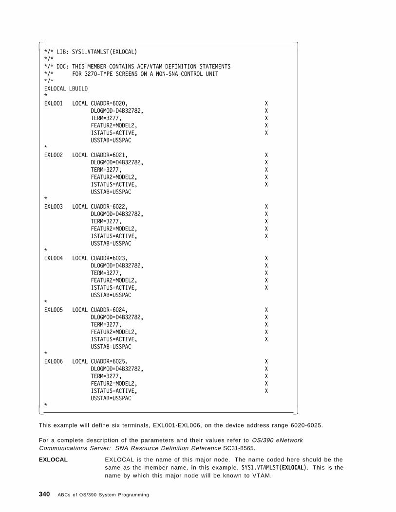
� �*/* LIB: SYS1.VTAMLST(EXLOCAL)*/**/* DOC: THIS MEMBER CONTAINS ACF/VTAM DEFINITION STATEMENTS*/* FOR 3270-TYPE SCREENS ON A NON-SNA CONTROL UNIT*/*EXLOCAL LBUILD*EXL001 LOCAL CUADDR=6020, X
DLOGMOD=D4B32782, XTERM=3277, XFEATUR2=MODEL2, XISTATUS=ACTIVE, XUSSTAB=USSPAC
*EXL002 LOCAL CUADDR=6021, X
DLOGMOD=D4B32782, XTERM=3277, XFEATUR2=MODEL2, XISTATUS=ACTIVE, XUSSTAB=USSPAC
*EXL003 LOCAL CUADDR=6022, X
DLOGMOD=D4B32782, XTERM=3277, XFEATUR2=MODEL2, XISTATUS=ACTIVE, XUSSTAB=USSPAC
*EXL004 LOCAL CUADDR=6023, X
DLOGMOD=D4B32782, XTERM=3277, XFEATUR2=MODEL2, XISTATUS=ACTIVE, XUSSTAB=USSPAC
*EXL005 LOCAL CUADDR=6024, X
DLOGMOD=D4B32782, XTERM=3277, XFEATUR2=MODEL2, XISTATUS=ACTIVE, XUSSTAB=USSPAC
*EXL006 LOCAL CUADDR=6025, X
DLOGMOD=D4B32782, XTERM=3277, XFEATUR2=MODEL2, XISTATUS=ACTIVE, XUSSTAB=USSPAC
*� �
This example will define six terminals, EXL001-EXL006, on the device address range 6020-6025.
For a complete description of the parameters and their values refer to OS/390 eNetworkCommunications Server: SNA Resource Definition Reference SC31-8565.
EXLOCAL EXLOCAL is the name of this major node. The name coded here should be thesame as the member name, in this example, SYS1.VTAMLST(EXLOCAL). This is thename by which this major node will be known to VTAM.
340 ABCs of OS/390 System Programming

LBUILD LBUILD specifies that this major node is for LOCAL NON-SNA devices.
EXL001 The LUNAME (Logical Unit NAME) associated with this terminal.
LOCAL Defines this LU as type LOCAL.
CUADDR Specifies the physical device address of this terminal.
DLOGMOD Specifies the Default Logmode associated with this terminal. The logmode isused by VTAM to tailor the 3270 datastream to match the terminal′s capabilities.The D4B32782 logmode used in this example will incorporate parameters thatgive VTAM such information as the number of rows and columns that thisterminal can support and whether or not it can handle extended highlighting(colors, reverse video, etc.).
TERM Specifies a specific of terminal device type.
FEATUR2 Specifies some additional features that this non-SNA local device can support.
ISTATUS Specifies whether this terminal is to be activated when the major node isactivated.
USSTAB Specifies the table to use when this terminal is not connected to an application.It can include a “Welcome to the VTAM Network” USSMSG10 as well as shortcutcommands for connecting to other applications. For example, a USS table canhave an entry PROD so that instead of entering the command LOGONAPPLID(CICSPROD) to connect to the CICSPROD application, you can simply typePROD.
This member can be activated by the following VTAM Operator command:
� �V NET,ACT,ID=EXLOCAL� �
Appendix A. Network Management 341

A.2 XCA Major Node
The XCA major node is used to define an External Communication Adapter to VTAM. The followingexample is for an OSA device attached to a token ring network.
� �OSA1 VBUILD TYPE=XCA*OSAPORT PORT ADAPNO=0, OSA ADAPTER 0 X
CUADDR=D02, OSA DEVICE ADDRESS XMEDIUM=RING, TOKEN RING XSAPADDR=4, SERVICE ACCESS POINT XTIMER=30
*OSAGRP GROUP ANSWER=ON, PU DIAL TO VTAM CAPABILITY X
CALL=INOUT, BOTH WAYS SESSION SETUP ALLOWED XDIAL=YES, SWITCHED CONNECTION XAUTOGEN=(255,L,P), AUTOGEN 8 LINE/PU PAIRS XDYNPU=YES, PU′ s DYNAMICALLY ALLOCED XISTATUS=ACTIVE INITIAL STATUS ACTIVE� �
This example will define a token ring SNA port on device address D02.
For a complete description of the parameters and their values refer to OS/390 eNetworkCommunications Server: SNA Resource Definition Reference SC31-8565.
OSA1 OSA1 is the name of this major node.
VBUILD TYPE=XCA Defines this as an XCA type major node.
OSAPORT The name VTAM will use to refer to the port being defined.
CUADDR The device address of the port.
MEDIUM The type of connection. Ring for token ring.
SAPADDR Service Access Point address for this connection to the LAN. It must be amultiple of 4.
OSAGRP The group name by which VTAM will refer to this set of logical Line and PhysicalUnit pairs. When subsequent Switched major nodes are defined for tokenring-attached devices they will establish a connection via a logical Line and PUpair.
AUTOGEN Instead of coding 255 Line and PU pairs, the autogen parameters specifies that255 pairs are to be defined, Line names starting with L and PU names startingwith P. This will be sufficient for the simultaneous connection of up to 255downstream LAN-attached PUs.
ISTATUS Specifies that these devices are to be activated on startup.
This member can be activated by the VTAM Operator command:
� �V NET,ACT,ID=OSA1� �
342 ABCs of OS/390 System Programming

A.3 Switched major node
The Switched major node is used to define switched communication links to VTAM.
� �SWITCH1 VBUILD TYPE=SWNET, X
MAXGRP=1, ** NO. OF UNIQUE GROUP NAMES ** XMAXNO=1 ** NO. OF UNIQUE TELEPHONE NOS. **
*SWPUA PU ADDR=C1, ** PHYSICAL UNIT ADDRESS ** X
IDBLK=017, ** CONTROLLER ** XIDNUM=00001, ** USER 3174 SERIAL NUMBER HERE ** XDISCNT=NO, ** VTAM DOES NOT HANG UP ** XIRETRY=YES, ** RE-POLL AFTER TIMEOUT ** XPUTYPE=2, ** PU TYPE 2 ** XMAXOUT=7, ** MAXIMUM PIUS = RESPONSE ** XMAXDATA=2042, ** DATA PLUS HEADER ** XMODETAB=AMODE, ** LOGON MODE TABLE NAME ** XUSSTAB=AUSSTAB, ** USS TABLE NAME ** XDLOGMOD=SNX32702, ** LOGON MODE ENTRY 3270 EABs ** XPACING=0, ** SECONDARY RECEIVES ** XVPACING=0 ** PRIMARY SENDS **
SWLUA2 LU LOCADDR=2SWLUA3 LU LOCADDR=3SWLUA4 LU LOCADDR=4SWLUA5 LU LOCADDR=5SWLUA6 LU LOCADDR=6SWLUA7 LU LOCADDR=7� �
This example will define a Switched Physical Unit and 6 Logical Units.
For a complete description of the parameters and their values refer to OS/390 eNetworkCommunications Server: SNA Resource Definition Reference SC31-8565.
SWITCH1 The name by which VTAM will identify this major node.
VBUILD TYPE=SWNET Defines this as a Switched Major Node.
SWPUA PU The name by which VTAM will identify this PU
IDBLK A 3-digit hexadecimal number that identifies the device type. This value will beprovided in the documentation for the actual device. All devices of the sametype, such as a 3274, will have the same IDBLK value.
IDNUM A 5-digit hexadecimal value that uniquely identifies this device connection. Thisvalue will be provided in the documentation for the actual device. All devices ofthe same type, such as a 3274, will have the same IDBLK value. When thisdevice attempts to establish a connection with VTAM, the information providedon the setup request will include this IDNUM value. VTAM will then make aone-to-one match between the physical device and this PU definition.
SWLUA2 LU Logical Unit definition
LOCADDR The physical device will be configured to support a number of logical units atgiven addresses. These addresses will correspond to the LOCADDR addressesin the VTAM definition.
Appendix A. Network Management 343

A.4 Sample FTP start procedure
� �//FTPD PROC PARMS=′ ′//*********************************************************************//* *//* FTP for MVS TCP/IP Version 3 Release 1 Level 0 *//* *//*********************************************************************//FTPD EXEC PGM=FTPD,PARM=′ POSIX(ON) ALL31(ON)/&PARMS′//STEPLIB DD DSN=TCPIP.SEZALINK,DISP=SHR// DD DSN=CEE.SCEERUN,DISP=SHR//CEEDUMP DD SYSOUT=*//*//* SYSFTPD is used to specify the FTP.DATA file for the FTP//* server. The file can be any sequential data set, member//* of a partitioned data set (PDS), or HFS file.//*//* The SYSFTPD DD statement is optional. The search order for//* FTP.DATA is://* /etc/ftp.data//* SYSFTPD DD statement//* jobname.FTP.DATA//* SYS1.TCPPARMS(FTPDATA)//* tcpip.FTP.DATA//*//* If no FTP.DATA file is found, FTP default values are used.//* For information on FTP defaults, see the Customization//* and Administration Guide and TCP/IP OE MVS Applications//* Feature Guide.//SYSFTPD DD DISP=SHR,DSN=SYS1.TCPIP.PARMS(FTPDATA) �1�//*//* SYSTCPD explicitly identifies which file is to be//* used to obtain the parameters defined by TCPIP.DATA.//* The SYSTCPD DD statement should be placed in the JCL of//* the server. The file can be any sequential data set,//* member of a partitioned data set (PDS), or HFS file.//SYSTCPD DD DISP=SHR,DSN=SYS1.TCPIP.PARMS(TCPDATA) �2�� �
344 ABCs of OS/390 System Programming

A.5 Sample OAT/**********************************************************************//* File created 15:16:33 on 04/26/1999 *//**********************************************************************/
/*********************************************************************//* Start of OSA Address Table for CHPID 5C *//*********************************************************************//* All entries below that are preceeded by ′ s-′ indicate that the *//* field is settable during Put_OAT processing *//*********************************************************************/oathdr.1 = IOA_OAT_HDR /* Eyecatcher-Do not change */oathdr.2 = 5C /* CHPID */oathdr.3 = 8 /* s-Number of entries *//*********************************************************************//* Start of OAT entry 1 *//*********************************************************************/oat.1.1 = IOA_OATENTRY /* Eyecatcher- Do not delete*/oat.1.2 = All data is valid /* Valid data indicator */oat.1.3 = /* Partition name */oat.1.4 = 0 /* s-Partition number */oat.1.5 = 04 /* s-Unit address */oat.1.6 = 0D04 /* Device number */oat.1.7 = 5C /* Chpid */oat.1.8 = 0D00 /* Control unit number */oat.1.9 = configured /* Channel state */oat.1.10 = yes /* Device accessible */oat.1.11 = 02 /* Group size */oat.1.12 = passthru /* s-Entry type. One of: */
/* Passthru *//* SNA *//* Unassigned */
oat.1.13 = started and in use /* Entry descriptor *//*********************************************************************//* Start of Extended OAT entry *//*********************************************************************/passthru.1.1 = 1 /* s-Port number */passthru.1.2 = no /* s-Default LP (yes/no) */passthru.1.3 = 195.183.66.11 /* s-home IP address *//*********************************************************************//* Start of OAT entry 2 *//*********************************************************************/oat.2.1 = IOA_OATENTRY /* Eyecatcher- Do not delete*/oat.2.2 = All data is valid /* Valid data indicator */oat.2.3 = /* Partition name */oat.2.4 = 0 /* s-Partition number */oat.2.5 = 05 /* s-Unit address */oat.2.6 = 0D05 /* Device number */oat.2.7 = 5C /* Chpid */oat.2.8 = 0D00 /* Control unit number */oat.2.9 = configured /* Channel state */oat.2.10 = yes /* Device accessible */oat.2.11 = 02 /* Group size */oat.2.12 = passthru /* s-Entry type. One of: */
/* Passthru *//* SNA *//* Unassigned */
oat.2.13 = started and in use /* Entry descriptor */
Appendix A. Network Management 345

/*********************************************************************//* Start of Extended OAT entry *//*********************************************************************/passthru.2.1 = 1 /* s-Port number */passthru.2.2 = no /* s-Default LP (yes/no) */passthru.2.3 = 195.183.66.11 /* s-home IP address *//*********************************************************************//* Start of OAT entry 3 *//*********************************************************************/oat.3.1 = IOA_OATENTRY /* Eyecatcher- Do not delete*/oat.3.2 = All data is valid /* Valid data indicator */oat.3.3 = /* Partition name */oat.3.4 = 0 /* s-Partition number */oat.3.5 = 02 /* s-Unit address */oat.3.6 = 0D02 /* Device number */oat.3.7 = 5C /* Chpid */oat.3.8 = 0D00 /* Control unit number */oat.3.9 = configured /* Channel state */oat.3.10 = yes /* Device accessible */oat.3.11 = 01 /* Group size */oat.3.12 = SNA /* s-Entry type. One of: */
/* Passthru *//* SNA *//* Unassigned */
oat.3.13 = started and in use /* Entry descriptor *//*********************************************************************//* Start of Extended OAT entry *//*********************************************************************/sna.3.1 = 00 /* s-Port number *//*********************************************************************//* Start of OAT entry 4 *//*********************************************************************/oat.4.1 = IOA_OATENTRY /* Eyecatcher- Do not delete*/oat.4.2 = Channel subsystem valid /* Valid data indicator */oat.4.3 = /* Partition name */oat.4.4 = 0 /* s-Partition number */oat.4.5 = 00 /* s-Unit address */oat.4.6 = 0D00 /* Device number */oat.4.7 = 5C /* Chpid */oat.4.8 = 0D00 /* Control unit number */oat.4.9 = configured /* Channel state */oat.4.10 = yes /* Device accessible */oat.4.11 = N/A /* Group size */oat.4.12 = N/A /* s-Entry type. One of: */
/* Passthru *//* SNA *//* Unassigned */
oat.4.13 = N/A /* Entry descriptor *//*********************************************************************//* Start of OAT entry 5 *//*********************************************************************/oat.5.1 = IOA_OATENTRY /* Eyecatcher- Do not delete*/oat.5.2 = Channel subsystem valid /* Valid data indicator */oat.5.3 = /* Partition name */oat.5.4 = 0 /* s-Partition number */oat.5.5 = 01 /* s-Unit address */oat.5.6 = 0D01 /* Device number */oat.5.7 = 5C /* Chpid */oat.5.8 = 0D00 /* Control unit number */
346 ABCs of OS/390 System Programming

oat.5.9 = configured /* Channel state */oat.5.10 = yes /* Device accessible */oat.5.11 = N/A /* Group size */oat.5.12 = N/A /* s-Entry type. One of: */
/* Passthru *//* SNA *//* Unassigned */
oat.5.13 = N/A /* Entry descriptor *//*********************************************************************//* Start of OAT entry 6 *//*********************************************************************/oat.6.1 = IOA_OATENTRY /* Eyecatcher- Do not delete*/oat.6.2 = Channel subsystem valid /* Valid data indicator */oat.6.3 = /* Partition name */oat.6.4 = 0 /* s-Partition number */oat.6.5 = 03 /* s-Unit address */oat.6.6 = 0D03 /* Device number */oat.6.7 = 5C /* Chpid */oat.6.8 = 0D00 /* Control unit number */oat.6.9 = configured /* Channel state */oat.6.10 = yes /* Device accessible */oat.6.11 = N/A /* Group size */oat.6.12 = N/A /* s-Entry type. One of: */
/* Passthru *//* SNA *//* Unassigned */
oat.6.13 = N/A /* Entry descriptor *//*********************************************************************//* Start of OAT entry 7 *//*********************************************************************/oat.7.1 = IOA_OATENTRY /* Eyecatcher- Do not delete*/oat.7.2 = Channel subsystem valid /* Valid data indicator */oat.7.3 = /* Partition name */oat.7.4 = 0 /* s-Partition number */oat.7.5 = 06 /* s-Unit address */oat.7.6 = 0D06 /* Device number */oat.7.7 = 5C /* Chpid */oat.7.8 = 0D00 /* Control unit number */oat.7.9 = configured /* Channel state */oat.7.10 = yes /* Device accessible */oat.7.11 = N/A /* Group size */oat.7.12 = N/A /* s-Entry type. One of: */
/* Passthru *//* SNA *//* Unassigned */
oat.7.13 = N/A /* Entry descriptor *//*********************************************************************//* Start of OAT entry 8 *//*********************************************************************/oat.8.1 = IOA_OATENTRY /* Eyecatcher- Do not delete*/oat.8.2 = Channel subsystem valid /* Valid data indicator */oat.8.3 = /* Partition name */oat.8.4 = 0 /* s-Partition number */oat.8.5 = 07 /* s-Unit address */oat.8.6 = 0D07 /* Device number */oat.8.7 = 5C /* Chpid */oat.8.8 = 0D00 /* Control unit number */oat.8.9 = configured /* Channel state */oat.8.10 = yes /* Device accessible */
Appendix A. Network Management 347

oat.8.11 = N/A /* Group size */oat.8.12 = N/A /* s-Entry type. One of: */
/* Passthru *//* SNA *//* Unassigned */
oat.8.13 = N/A /* Entry descriptor *//**********************************************************************/******************* End of OAT entries *************************/**********************************************************************
/*-------------------------------------------------------------------*//* Examples of Extended OAT entries start here *//*********************************************************************//* Passthru extended entry example *//* --change IP address to match TCPIP profile *//*********************************************************************//* passthru.n.1 = PORT_NUMBER /* s-Port number (1 hex digit)*//* passthru.n.2 = yes or no /* s-Default LP (yes/no) *//* passthru.n.3 = IP address /* s-home IP address (w.x.y.z)*//*********************************************************************//* SNA extended entry WITHOUT Network managment example *//*********************************************************************//* sna.n.1 = PORT_NUMBER /* s-Port number (1 hex digit)*//*********************************************************************//* SNA extended entry WITH Network managment example *//* --change VTAM IDNUM to match value on XCA node definition *//*********************************************************************//* sna.n.1 = FF /* s-Port number (must be FF) *//* sna.n.2 = VTAM IDNUM /* s-VTAM IDNUM (5 hex chars) *//**********************************************************************/************* END of Extended OAT entry examples ***************/**********************************************************************
348 ABCs of OS/390 System Programming

Appendix B. Special Notices
This publication is intended to help new system programmers who need to understand S/390 and theOS/390 operating system. The information in this publication is not intended as the specification of anyprogramming interfaces that are provided by OS/390 Versions. See the PUBLICATIONS section of theIBM Programming Announcement for OS/390 Version 2 Release 8, Program Number 5647-A01 for moreinformation about what publications are considered to be product documentation.
References in this publication to IBM products, programs or services do not imply that IBM intends tomake these available in all countries in which IBM operates. Any reference to an IBM product,program, or service is not intended to state or imply that only IBM′s product, program, or service maybe used. Any functionally equivalent program that does not infringe any of IBM ′s intellectual propertyrights may be used instead of the IBM product, program or service.
Information in this book was developed in conjunction with use of the equipment specified, and islimited in application to those specific hardware and software products and levels.
IBM may have patents or pending patent applications covering subject matter in this document. Thefurnishing of this document does not give you any license to these patents. You can send licenseinquiries, in writing, to the IBM Director of Licensing, IBM Corporation, North Castle Drive, Armonk, NY10504-1785.
Licensees of this program who wish to have information about it for the purpose of enabling: (i) theexchange of information between independently created programs and other programs (including thisone) and (ii) the mutual use of the information which has been exchanged, should contact IBMCorporation, Dept. 600A, Mail Drop 1329, Somers, NY 10589 USA.
Such information may be available, subject to appropriate terms and conditions, including in somecases, payment of a fee.
The information contained in this document has not been submitted to any formal IBM test and isdistributed AS IS. The use of this information or the implementation of any of these techniques is acustomer responsibility and depends on the customer ′s ability to evaluate and integrate them into thecustomer ′s operational environment. While each item may have been reviewed by IBM for accuracy ina specific situation, there is no guarantee that the same or similar results will be obtained elsewhere.Customers attempting to adapt these techniques to their own environments do so at their own risk.
Any pointers in this publication to external Web sites are provided for convenience only and do not inany manner serve as an endorsement of these Web sites.
Reference to PTF numbers that have not been released through the normal distribution process doesnot imply general availability. The purpose of including these reference numbers is to alert IBMcustomers to specific information relative to the implementation of the PTF when it becomes availableto each customer according to the normal IBM PTF distribution process.
You can reproduce a page in this document as a transparency, if that page has the copyright notice onit. The copyright notice must appear on each page being reproduced.
The following terms are trademarks of the International Business Machines Corporation in the UnitedStates and/or other countries:
ACF/VTAM Advanced Function PrintingAFP AnyNetCICS CICS/ESACICS/MVS DB2
Copyright IBM Corp. 2000 349
The following terms are trademarks of other companies:
The following terms are trademarks of other companies:
Tivoli, Manage. Anything. Anywhere., The Power To Manage.,Anything. Anywhere., TME, NetView, Cross-Site, Tivoli Ready,Tivoli Certified, Planet Tivoli, and Tivoli Enterprise aretrademarks or registered trademarks of Tivoli Systems Inc., anIBM company, in the United States, other countries, or both.In Denmark, Tivoli is a trademark licensed from Kjobenhavns Sommer -Tivoli A/S.
C-bus is a trademark of Corollary, Inc. in the United States and/orother countries.
Java and all Java-based trademarks and logos are trademarks or registeredtrademarks of Sun Microsystems, Inc. in the United States and/or other countries.
Microsoft, Windows, Windows NT, and the Windows logo are trademarks ofMicrosoft Corporation in the United States and/or other countries.
PC Direct is a trademark of Ziff Communications Company in the United Statesand is used by IBM Corporation under license.
ActionMedia, LANDesk, MMX, Pentium and ProShare are trademarks of IntelCorporation in the United States and/or other countries.
SET, SET Secure Electronic Transaction, and the SET logo are trademarksowned by Secure Electronic Transaction LLC.
UNIX is a registered trademark in the United States and othercountries licensed exclusively through the Open Group.
Other company, product, and service names may be trademarks orservice marks of others.
DFSMS DFSMS/MVSDFSMSdfp DFSMSdssDFSMShsm DFSMSrmmDFSORT ESCONFICON IBMIMS InfoPrintIntelligent Printer Data Stream IPDSIP PrintWay Language EnvironmentMVS (block letters) MVS/DFPNetSpool NetViewOpenEdition OS/390Parallel Sysplex PrintWayRACF RAMACRMF S/390S/390 Parallel Enterprise Server Sysplex TimerVTAM
350 ABCs of OS/390 System Programming

Appendix C. Related Publications
The publications listed in this section are considered particularly suitable for a more detaileddiscussion of the topics covered in this redbook.
C.1 IBM Redbooks
For information on ordering these ITSO publications see “How to get IBM Redbooks” on page 355.
• OS/390 Release 5 Implementation, SG24-5151
• OS/390 Release 4 Implementation, SG24-2089
• OS/390 Release 3 Implementation, SG24-2067
• OS/390 Release 2 Implementation, SG24-4834
• cit.OS/390 Security Server 1999 Updates Technical Presentation Guide, SG24-5627
• Security in OS/390-based TCP/IP Networks, SG24-5383
• Hierarchical File System Usage Guide, SG24-5482
• Enhanced Catalog Sharing and Management, SG245594
• Integrated Catalog Facility Backup and Recovery, SG24-5644
• OS/390 Version 2 Release 6 UNIX System Services Implementation and Customiztion, SG24-5178
• IBM S/390 FICON Implementation Guide, SG24-5169
• Exploiting S/390 Hardware Cryptography with Trusted Key Entry, SG24-5455
• TCP/IP Tutorial and Technical Overview, GG24-3376
• Introduction to Storage Area Network SAN, SG2-45470
• TCP/IP in a Sysplex, SG24-5235
• SecureWay Communications Server for OS/390 V2R8 TCP/IP: Guide to Enhancements, SG24-5631
• OS/390 eNetwork Communications Server V2R7 TCP/IP Implementation Guide Volume 1:Configuration and Routing, SG24-5227
• OS/390 eNetwork Communications Server V2R7 TCP/IP Implementation Guide Volume 3: MVSApplications, SG24-5229
• OS/390 Workload Manager Implementation and Exploitation, SG24-5326
• ADSM Server-to-Server Implementation and Operation, SG24-5244
• Stay Cool on OS/390: Installing Firewall Technology, SG24-2046
• Implementing DFSMSdss SnapShot and Virtual Concurrent Copy, SG24-5268
• TCP/IP OpenEdition Implementation Guide, SG24-2141
• IMS/ESA Version 5 Performance Guide, SG24-4637
• Parallel Sysplex Configuration: Overview, SG24-2075
• Parallel Sysplex Configuation: Cookbook, SG24-2076
• Parallel Sysplex Config.: Connectivity, SG24-2077
• DFSMS Optimizer Presentation Guide Update, SG24-4477
• MVS Parallel Sysplex Capacity Planning, SG24-4680
Copyright IBM Corp. 2000 351

• Getting the Most Out of a Parallel Sysplex, SG24-2073
• OS/390 eNetwork Communication Server TCP/IP Implementation Guide Volume 2, SG24-5228
C.2 IBM Redbooks collections
Redbooks are also available on the following CD-ROMs. Click the CD-ROMs button athttp://www.redbooks.ibm.com/ for information about all the CD-ROMs offered, updates and formats.
C.3 Other resources
These publications are also relevant as further information sources:
• OS/390 Initialization and Tuning Guide, SC28-1751
• OS/390 Initialization and Tuning Reference, SC28-1752
• OS/390 Introduction and Release Guide, GC28-1725
• OS/390 MVS JCL User′s Guide, SC28-1758
• OS/390 MVS JCL Reference, GC28-1757
• OS/390 MVS System Diagnosis: Tools and Service Aids, LY28-1085, (available to IBM licensedcustomers only)
• Interactive System Productivity Facility Getting Started, SC34-4440
• OS/390 Security Server (RACF) System Programmer ′s Guide, SC28-1913
• OS/390 TSO/E Customization, SC28-1965
• OS/390 TSO/E Primer, GC28-1967
• OS/390 TSO/E User′s Guide, SC28-1968
• OS/390 SMP/E Reference, SC28-1806
• OS/390 SMP/E User′s Guide, SC28-1740
• OS/390 SMP/E Commands, SC28-1805
• Standard Packaging Rules for MVS-Based Products, SC23-3695
• OS/390 MVS System Commands, GC28-1781
• OS/390 MVS IPCS Commands, GC28-1754
• OS/390 MVS IPCS User′s Guide, GC28-1756
• DFSMS/MVS Using Data Sets, SC26-4922
• OS/390 Planning for Installation, GC28-1726
• OS/390 MVS System Data Sets Definition, GC28-1782
CD-ROM Title Collection Kit NumberSystem/390 Redbooks Collection SK2T-2177Networking and Systems Management Redbooks Collection SK2T-6022Transaction Processing and Data Management Redbooks Collection SK2T-8038Lotus Redbooks Collection SK2T-8039Tivoli Redbooks Collection SK2T-8044AS/400 Redbooks Collection SK2T-2849Netfinity Hardware and Software Redbooks Collection SK2T-8046RS/6000 Redbooks Collection (BkMgr Format) SK2T-8040RS/6000 Redbooks Collection (PDF Format) SK2T-8043Application Development Redbooks Collection SK2T-8037IBM Enterprise Storage and Systems Management Solutions SK3T-3694
352 ABCs of OS/390 System Programming

• ICKDSF R16 Refresh, User′s Guide, GC35-0033
• OS/390 MVS System Management Facilities (SMF), GC28-1783
• EREP V3R5 Reference, GC35-0152
• OS/390 JES2 Commands, GC28-1790
• OS/390 Hardware Configuration Definition User′s Guide, SC28-1848
• DFSMS/MVS DFSMSdss Storage Administration Reference, SC26-4929
• IBM ServerPac for OS/390 Using the Installation Dialog, SC28-1244
• OS/390 Hardware Configuration Definition Planning, GC28-1750
• OS/390 MVS Using the Subsystem Interface, SC28-1502
• DFSMS/MVS Version 1 Release 4: Managing Catalogs, SC26-4914
• DFSMS/MVS Version 1 Release4: Access Method Services for Integrated Catalog Facility, SC26-4906
• DFSMS/MVS: DFSMShsm Implementation and Customization Guide, SH21-1078
• DFSMS/MVS Access Method Services for ICF Catalogs, SC26-4500
• DFSMS/MVS DFSMSdfp Storage Administration Reference, SC26-4920
• OS/390 eNetwork Communications Server: SNA Resource Definition Reference, SC31-8565
• OS/390 eNetwork Communications Server SNA Resource Definition Samples, SC31-8566
• OS/390 eNetwork Communications Server: SNA Operation, SC31-8567
• OS/390 V2R7.0 eNetwork CS IP Configuration, SC31-8513
• eNetwork Communications Server: IP User′s Guide GC31-8514
• OS/390 UNIX System Services Planning, SC28-1890
• OS/390 TCP/IP OpenEdition: Configuration Guide SC31-8304
• OS/390 Open Systems Adapter Support Facility User′s Guide, SC28-1855.
• OS/390 V2R6.0 MVS Planning: APPC/MVS Management, GC28-1807
• Print Services Facility for OS/390: Customization, S544-5622
• DFSMS/MVS Planning for Installation, SC26-4919
• DFSMS/MVS Implementing System-Managed Storage, SC26-3123
• DFSMS/MVS Remote Copy Administrator′s Guide and Reference, SC35-0169
• DFSMS/MVS Macro Instructions for Data Sets, SC26-4913
• DFSMS/MVS DFSMSdfp Diagnosis Guide, SY27-9605
• DFSMS/MVS DFSMSdfp Advanced Services, SC26-4921
• DFSMS/MVS Using Magnetic Tapes, SC26-4923
• DFSMS/MVS Utilities, SC26-4926
• Service Level Reporter User′s Guide: Reporting, SH19-6530
• DFSMS/MVS Object Access Method Application Programmer ′s Reference, SC26-4917
• DFSMS/MVS Object Access Method Planning, Installation, and Storage Administration Guide forObject Support, SC26-4918
• DFSORT Installation and Customization, SC26-7041
• DFSORT Getting Started with DFSORT R14, SC26-4109
• DFSMS/MVS Network File System Customization and Operation, SC26-7029
Appendix C. Related Publications 353

• DFSMS Optimizer User′s Guide and Reference, SC26-7047
• DFSMS/MVS DFSMSdss Storage Administration Guide, SC26-4930
• DFSMShsm Storage Administration Guide, SH21-1076
• DFSMShsm Storage Administration Reference, SH21-1075
• DFSMS/MVS Network File System User′s Guide, SC26-7028
• DFSMS/MVS DFSMSrmm Guide and Reference, SC26-4931
• DFSMS/MVS DFSMSrmm Implementation and Customization Guide, SC26-4932
• MVS/ESA Storage Management Library Managing Data, SC26-3124
• MVS/ESA Storage Management Library Managing Storage Groups, SC26-3125
• MVS/ESA Storage Management Library Leading a Storage Administration Group, SC26-3126.
• DFSMS/MVS Using the Interactive Storage Management Facility, SC26-4911
• ADSTAR Distributed Storage Manager for MVS Administrator′s Guide, GC35-0277
• OS/390 MVS Programming: Assembler Services Guide, GC28-1762
• OS/390 MVS Programming: Resource Recovery, GC28-1739
• OS/390 MVS Setting Up a Sysplex, GC28-1779
• OS/390 MVS Sysplex Services Guide, GC28-1771
• OS/390 Parallel Sysplex Systems Management, GC28-1861
• OS/390 MVS Systems Codes, GC28-1780
• OS/390 MVS System Messages Volume 1, GC28-1784
• OS/390 MVS System Messages Volume 2, GC28-1785
• OS/390 MVS System Messages Volume 3, GC28-1786
• OS/390 MVS System Messages Volume 4, GC28-1787
• OS/390 MVS System Messages Volume 5, GC28-1788
• OS/390 MVS Installation Exits, SC28-1753
• OS/390 MVS Diagnosis Reference, SY28-1084
• CICS User′s Handbook, SX33-1188
• CICS Diagnosis Guide, LX33-6093
• MQSeries for MVS/ESA Messages and Codes, GC33-0819
354 ABCs of OS/390 System Programming

How to get IBM Redbooks
This section explains how both customers and IBM employees can find out about IBM Redbooks, redpieces, andCD-ROMs. A form for ordering books and CD-ROMs by fax or e-mail is also provided.
• Redbooks Web Site http://www.redbooks.ibm.com/
Search for, view, download, or order hardcopy/CD-ROM Redbooks from the Redbooks Web site. Also readredpieces and download additional materials (code samples or diskette/CD-ROM images) from this Redbookssite.
Redpieces are Redbooks in progress; not all Redbooks become redpieces and sometimes just a few chapterswill be published this way. The intent is to get the information out much quicker than the formal publishingprocess allows.
• E-mail Orders
Send orders by e-mail including information from the redbook fax order form to:
• Telephone Orders
• Fax Orders
This information was current at the time of publication, but is continually subject to change. The latest informationmay be found at the Redbooks Web site.
IBM Intranet for Employees
IBM employees may register for information on workshops, residencies, and Redbooks by accessing the IBMIntranet Web site at http://w3.itso.ibm.com/ and clicking the ITSO Mailing List button. Look in the Materialsrepository for workshops, presentations, papers, and Web pages developed and written by the ITSO technicalprofessionals; click the Additional Materials button. Employees may access MyNews at http://w3.ibm.com/ forredbook, residency, and workshop announcements.
In United States: e-mail address: [email protected] North America: Contact information is in the ″How to Order″ section at this site:
http://www.elink.ibmlink.ibm.com/pbl/pbl/
United States (toll free) 1-800-879-2755Canada (toll free) 1-800-IBM-4YOUOutside North America Country coordinator phone number is in the ″How to Order″ section at this site:
http://www.elink.ibmlink.ibm.com/pbl/pbl/
United States (toll free) 1-800-445-9269Canada 1-403-267-4455Outside North America Fax phone number is in the ″How to Order″ section at this site:
http://www.elink.ibmlink.ibm.com/pbl/pbl/
Copyright IBM Corp. 2000 355

IBM Redbooks fax order form
Please send me the following:
Title Order Number Quantity
First name Last name
Company
Address
City Postal code Country
Telephone number Telefax number VAT number
• Invoice to customer number
• Credit card number
Credit card expiration date Card issued to Signature
We accept American Express, Diners, Eurocard, Master Card, and Visa. Payment by credit card notavailable in all countries. Signature mandatory for credit card payment.
356 ABCs of OS/390 System Programming

abend
Glossary
Aabend . Termination of a task before its completionbecause of an error condition that cannot be resolvedby recovery facilities while the task executing.
ACB . Access method control block.
access . A specific type of interaction between asubject and an object that results in the flow ofinformation from one to the other.
access authority . An authority that relates to arequest for a type of access to protected resources.In RACF, the access authorities are NONE, READ,UPDATE, ALTER, and EXECUTE.
access list . A list within a profile of all authorizedusers and their access authorities.
access method control block (ACB). . A control blockthat links an application program to VTAM.
ACDS . Active control data set.
ACF/VTAM . An IBM licensed program that controlscommunication and the flow of data in an SNAnetwork. It provides single-domain, multiple-domain,and interconnected network capability. VTAM runsunder MVS (OS/VS1 and OS/VS2), VSE, and VM/SPand supports direct control application programs andsubsystems such as VSE/POWER.
ACIF . (1) AFP conversion and indexing facility. (2) APSF utility program that converts a print file into AFP,MO:DCA-P, creates an index file for input data, andcollects resources used by an AFP document intoseparate file.
action message retention facility (AMRF) . A facilitythat, when active, retains all action messages exceptthose specified by the installation in the MPFLSTxxmember in effect.
action message sequence number . A decimalnumber assigned to action messages.
Advanced Function Presentation (AFP) . A set oflicensed programs, together with user applications,that use the all-points-addressable concept to print onpresentation devices. AFP includes creating,formatting, archiving, retrieving, viewing, distributing,and printing information.
Advanced Program-to-Program Communications(APPC) . A set of inter-program communicationservices that support cooperative transactionprocessing in a SNA network.
AFP . Advanced Function Presentation.
AFP Printer Driver for Windows . A component ofInfoprint Server for OS/390 that runs on a Windows 95or Windows NT workstation and creates output in AFPformat, for printing on AFP printers.
AFP Viewer plug-in for Windows . A component ofInfoprint Server for OS/390 that runs on a Windows 95or Windows NT workstation and allows you to viewfiles in AFP format.
AIX operating system . IBM′s implementation of theUNIX operating system. The RS/6000 system, amongothers, runs the AIX operating system.
allocate . To assign a resource for use in performinga specific task.
alphanumeric character . A letter or a number.
amode . Addressing mode. A program attribute thatcan be specified (or defaulted) for each CSECT, loadmodule, and load module alias. AMODE states theaddressing mode that is expected to be in effect whenthe program is entered.
AMRF . action message retention facility
AOR . Application-owning region
APPC . Advanced Program-to-ProgramCommunications
APPN . Advanced Peer-to-Peer Networking.
ASCII (American Standard Code for InformationInterchange) . The standard code, using a codedcharacter set consisting of 7-bit coded characters(8-bit including parity check), that is used forinformation interchange among data processingsystems, data communication systems, andassociated equipment. The ASCII set consists ofcontrol characters and graphic characters.
audit . To review and examine the activities of a dataprocessing system mainly to test the adequacy andeffectiveness of procedures for data security and dataaccuracy.
authority . The right to access objects, resources, orfunctions.
authorization checking . The action of determiningwhether a user is permitted access to aRACF-protected resource.
Authorized Program Analysis Report (APAR) . Arequest for correction of problem caused by a defectin a current unaltered release of a program.
Copyright IBM Corp. 2000 357
authorized program facility (APF)
authorized program facility (APF) . A facility thatpermits identification of programs authorized to userestricted functions.
automated operations . Automated procedures toreplace or simplify actions of operators in bothsystems and network operations.
AVR . Automatic volume recognition.
Bbanner page . A page printed before the data set isprinted.
basic mode . A central processor mode that does notuse logical partitioning. Contrast with logicallypartitioned (LPAR) mode.
batch message processing (BMP) program . An IMSbatch processing program that has access to onlinedatabases and message queues. BMPs run online,but like programs in a batch environment, they arestarted with job control language (JCL).
batch-oriented BMP program . A BMP program thathas access to online databases and message queueswhile performing batch-type processing. Abatch-oriented BMP does not access the IMS messagequeues for input or output. It can access onlinedatabases, GSAM databases, and MVS files for bothinput and output.
BMP . Batch message processing (BMP) program.
broadcast . (1) Transmission of the same data to alldestinations. (2) Simultaneous transmission of datato more than one destination.
binary data . (1) Any data not intended for directhuman reading. Binary data may contain unprintablecharacters, outside the range of text characters. (2) Atype of data consisting of numeric values stored in bitpatterns of 0s and 1s. Binary data can cause a largenumber to be placed in a smaller space of storage.
BIND . In SNA, a request to activate a sessionbetween two logical units (LUs).
buffer . A portion of storage used to hold input oroutput data temporarily.
buffered device . A device where the data is writtento a hardware buffer in the device before it is placedon the paper (for example, IBM 3820).
burst . To separate continuous-forms paper intosingle sheets.
Ccache structure . A coupling facility structure thatenables high-performance sharing of cached data bymultisystem applications in a sysplex. Applicationscan use a cache structure to implement severaldifferent types of caching systems, including astore-through or a store-in cache.
carriage control character . An optional character inan input data record that specifies a write, space, orskip operation.
carriage return (CR) . (1) A keystroke generallyindicating the end of a command line. (2) In text data,the action that indicates to continue printing at theleft margin of the next line. (3) A character that willcause printing to start at the beginning of the samephysical line in which the carriage return occurred.
CART . Command and response token.
case-sensitive . Pertaining to the ability to distinguishbetween uppercase and lowercase letters.
catalog . (1) A directory of files and libraries, withreference to their locations. (2) To enter informationabout a file or a library into a (3) The collection of alldata set indexes that are used by the control programto locate a volume containing a specific data set.
CBPDO . Custom Built Product Delivery Offering.
CEC. Synonym for central processor complex (CPC).
central processor (CP) . The part of the computer thatcontains the sequencing and processing facilities forinstruction execution, initial program load, and othermachine operations.
central processor complex (CPC) . A physicalcollection of hardware that includes main storage, oneor more central processors, timers, and channels.
CFRM . Coupling facility resource management.
channel-to-channel (CTC) . Refers to thecommunication (transfer of data between programs onopposite sides of a channel-to-channel adapter (CTCA
channel-to-channel adapter (CTCA) . An input/outputdevice that is used a program in one system tocommunicate with a program in another system.
checkpoint . (1) A place in a routine where a check,or a recording of data for restart purposes, isperformed. (2) A point at which information about thestatus of a job and the system can be recorded sothat the job step can be restarted later.
checkpoint write . Any write to the checkpoint dataset. A general term for the primary, intermediate, andfinal writes that update any checkpoint data set.
358 ABCs of OS/390 System Programming

CICS
CICS. Customer Information Control System.
CICSplex . A group of connected CICS regions.
CICSPlex SM . CICSPlex System Manager
client . A functional unit that receives shared servicesfrom a server. See also client-server.
client-server . In TCP/IP, the model of interaction indistributed data processing in which a program at onesite sends a request to a program at another site andawaits a response. The requesting program is calleda client; the answering program is called a server.
CMOS . Complementary metal-oxide semiconductor.
CNGRPxx . The SYS1.PARMLIB member that definesconsole groups for the system or sysplex.
code page . (1) A table showing codes assigned tocharacter sets. (2) An assignment of graphiccharacters and control function meanings to all codepoints. (3) Arrays of code points representingcharacters that establish ordinal sequence (numericorder) of characters. (4) A particular assignment ofhexadecimal identifiers to graphic elements.
code point . A 1-byte code representing one of 256potential characters.
coexistence . Two or more systems at different levels(for example, software, service or operational levels)that share resources. Coexistence includes the abilityof a system to respond in the following ways to a newfunction that was introduced on another system withwhich it shares resources: ignore a new function,terminate gracefully, support a new function.
command and response token (CART) . A parameteron WTO, WTOR, MGCRE, and certain TSO/Ecommands and REXX execs that allows you to linkcommands and their associated message responses.
command prefix facility (CPF) . An MVS facility thatallows you to define and control subsystem and othercommand prefixes for use in a sysplex.
COMMDS . Communications data set.
complementary metal-oxide semiconductor (CMOS) .A technology that combines the electrical propertiesof positive and negative voltage requirements to useconsiderably less power than other types ofsemiconductors.
connection . In TCP/IP, the path between two protocolapplications that provides reliable data streamdelivery service. In Internet communications, aconnection extends from a TCP application on onesyste system to a TCP application on another system.
console . That part of a computer used forcommunication between the operator or user and thecomputer.
console group . In MVS, a group of consoles definedin CNGRPxx, each of whose members can serve as analternate console in console or hardcopy recovery oras a console to display synchronous messages.
CONSOLxx . The SYS1.PARMLIB member used todefine message handling, command processing, andMCS consoles.
control unit . Synonymous with device control unit.
conversation . A logical connection between twoprograms over an LU type 6.2 session that allowsthem to communicate with each other whileprocessing a transaction.
conversational . Pertaining to a program or a systemthat carries on a dialog with a terminal user,alternately accepting input and then responding to theinput quickly enough for the user to maintain a trainof thought.
copy group . One or more copies of a page of paper.Each copy can have modifications, such as textsuppression, page position, forms flash, and overlays.
couple data set . A data set that is created throughthe XCF couple data set format utility and, dependingon its designated type, is shared by some or all of theMVS systems in a sysplex. See also sysplex coupledata set.
coupling facility . A special logical partition thatprovides high-speed caching, list processing, andlocking functions in a sysplex.
coupling facility channel. . A high bandwidth fiberoptic channel that provides the high-speedconnectivity required for data sharing between acoupling facility and the central processor complexesdirectly attached to it.
coupling services . In a sysplex, the functions of XCFthat transfer data and status between members of agroup residing on one or more MVS systems in thesysplex.
CP. Central processor.
CPC. Central processor complex.
CPF. Command prefix facility.
cross-system coupling facility (XCF) . XCF is acomponent of MVS that provides functions to supportcooperation between authorized programs runningwithin a sysplex.
cryptography . The transformation of data to concealits meaning.
Glossary 359

cryptographic key
cryptographic key . A parameter that determinescryptographic transformations between plaintext andciphertext.
CTC. Channel-to-channel.
Customer Information Control System (CICS) . AnIBM licensed program tha that enables transactionsentered at remote terminals to be processedconcurrently by user-written application programs. Itincludes facilities for building, using, and maintainingdatabases.
DDAE . Dump analysis and elimination.
daemon . A program that runs unattended to performa standard service.
DASD . Direct access storage device.
data definition name . The name of a data definition(DD) statement, which corresponds to a data controlblock that contains the same name. Abbreviated asddname.
data definition (DD) statement . A job controlstatement that describes a data set associated with aparticular job step.
data integrity . The condition that exists as long asaccidental or intentional destruction, alteration, orloss of data does not occur.
data set . The major unit of data storage andretrieval, consisting of a collection of data in one ofseveral prescribed arrangements and described bycontrol information to which the system has access.
data set label . (1) A collection of information thatdescribes the attributes of a data set and is normallystored on the same volume as the data set. (2) Ageneral term for data set control blocks and tape dataset labels.
data set separator pages . Those pages of printedoutput that delimit data sets.
data sharing . The ability of concurrent subsystems(such as DB2 or IMS DB) or application programs todirectly access and change the same data whilemaintaining data integrity.
data stream . (1) All information (data and controlcommands) sent over a data link usually in a singleread or write operation. (2) A continuous stream ofdata elements being transmitted, or intended fortransmission, in character or binary-digit form, usinga defined format.
DBCS . Double-byte character set.
DBCTL . IMS Database Control.
DBRC . Database Recovery Control.
DB2 . DATABASE 2 for MVS/ESA.
DB2 data sharing group . A collection of one or moreconcurrent DB2 subsystems that directly access andchange the same data while maintaining dataintegrity.
DB2 PM . DB2 Performance Monitor.
deallocate . To release a resource that is assigned toa specific task.
default . A value, attribute, or option that is assumedwhen no alternative is specified by the user.
destination node . The node that provides applicationservices to an authorized external user.
device control unit . A hardware device that controlsthe reading, writing, or displaying of data at one ormore input/output devices or terminals.
device number . The unique number assigned to anexternal device.
device type . The general name for a kind of device;for example, 3330.
DFSMS. Data Facility Storage ManagementSubsystem.
direct access storage device (DASD) . A device inwhich the access time effectively independent of thelocation of the data.
directory . (1) A type of file containing the names andcontroll ing information for other fi les or otherdirectories. Directories can also containsubdirectories, which can contain subdirectories oftheir own. (2) A file that contains directory entries.No two directory entries in the same directory canhave the same name. (POSIX.1). (3) A file that pointsto files and to other directories. (4) An index used bya control program to locate blocks of data that arestored in separate areas of a data set in direct accessstorage.
display console . In MVS, an MCS console whoseinput/output function you can control.
DLL filter . A filter that provides one or more of thesefunctions in a dynamic load library - init(), prolog(),process(), epilog(), and term(). See cfilter.h andcfilter.c in the /usr/lpp/Printsrv/samples/ directory formore information. See also filter. Contrast with DLLfilter.
DOM . An MVS macro that removes outstandingWTORs or action messages that have been queued toa console end-of-tape-marker. A marker on a
360 ABCs of OS/390 System Programming

dotted decimal notation
magnetic tape used to indicate the end of thepermissible recording area, for example, aphoto-reflective strip a transparent section of tape, ora particular bit pattern.
dotted decimal notation . The syntacticalrepresentation for a 32-bit integer that consists of four8-bit numbers written in base 10 with periods (dots)separating them. It is used to represent IP addresses.
double-byte character set (DBCS) . A set ofcharacters in which each character is represented bya two-bytes code. Languages such as Japanese,Chinese, and Korean, which contain more symbolsthan can be represented by 256 code points, requiredouble-byte character sets. Because each characterrequires two bytes, the typing, display, and printing ofDBCS characters requires hardware and programsthat support DBCS. Contrast with single-bytecharacter set.
drain . Allowing a printer to complete its current workbefore stopping the device.
Eentry area . In MVS, the part of a console screenwhere operators can enter commands or commandresponses.
EMIF. ESCON Multiple Image Facility.
Enterprise Systems Connection (ESCON) . A set ofproducts and services that provides a dynamicallyconnected environment using optical cables as atransmission medium.
EPDM. IBM SystemView Enterprise PerformanceData Manager/MVS.
ESCD. ESCON Director.
ESCM. ESCON Manager. The licensed programSystem Automation for OS/390 includes all of thefunction previosuly provided by ESCM.
ESCON. Enterprise Systems Connection.
ETR. External Time Reference. See also SysplexTimer.
extended MCS console . In MVS, a console other thanan MCS console from which operators or programscan issue MVS commands and receive messages. Anextended MCS console is defined through anOPERPARM segment.
FFMID . Function modification identifier. The IBMrelease-specific product identifier such as HJE6610 forOS/390 Release 1 JES2.
FOR. File-owning region.
frame . For a System/390 microprocessor cluster, aframe contains one or two central processorcomplexes (CPCs), support elements, and AC powerdistribution.
FSS. functional subsystem. An address spaceuniquely identified as performing a specific functionrelated to the JES. An example of an FSS is theprogram Print Services Facility that operates the 3800Model 3 an 38xx printers.
functional subsystem (FSS) . An address spaceuniquely identified as performing a specific functionrelated to the JES.
functional subsystem application (FSA) . Thefunctional application program managed by thefunctional subsystem.
functional subsystem interface (FSI) . The interfacethrough which JES2 JES3 communicate with thefunctional subsystem.
Ggateway node . A node that is an interface betweennetworks.
generalized trace facility (GTF) . Like system trace,gathers information used to determine and diagnoseproblems that occur during system operation. Unlikesystem trace, however, GTF can be tailored to recordvery specific system and user program events.
global access checking . The ability to allow aninstallation to establish an in-storage table of defaultvalues for authorization levels for selected resources.
global resource serialization . A function thatprovides an MVS serialization mechanism forresources (typically data sets) across multiple MVSimages.
global resource serialization complex . One or moreMVS systems that use global resource serialization toserialize access to shared resources (such as datasets on shared DASD volumes).
group . A collection of RACF users who can shareaccess authorities for protected resources.
GTF. Generalized trace facility.
Glossary 361

hardcopy log
Hhardcopy log . In systems with multiple consolesupport or a graphic console, a permanent record ofsystem activity.
hardware . Physical equipment, as opposed to thecomputer program or method of use; for example,mechanical, magnetic, electrical, or electronicdevices. Contrast with software.
hardware configuration dialog . In MVS, a panelprogram that is part of the hardware configurationdefinition. The program allows an installation todefine devices for MVS system configurations.
Hardware Management Console . A console used tomonitor and control hardware such as the System/390microprocessors.
HCD. Hardware Configuration Definition.
highly parallel . Refers to multiple systems operatingin parallel, each of which can have multipleprocessors. See also n-way.
IICMF . Integrated Coupling Migration Facility.
IMS . Information Management System.
IMS DB . Information Management System DatabaseManager.
IMS DB data sharing group . A collection of one ormore concurrent IMS DB subsystems that directlyaccess and change the same data while maintainingdata integrity.
IMS TM. Information Management SystemTransaction Manager.
initial program load (IPL) . The initialization procedurethat causes an operating system to begin operation.
instruction line . In MVS, the part of the consolescreen that contains messages about console controland input errors.
internal reader . A facility that transfers jobs to thejob entry subsystem (JES2 or JES3).
IOCDS. Input/output configuration data set.
IOCP. Input/output configuration program.
IODF. Input/output definition file.
IPL . Initial program load.
IRLM . Internal resource lock manager.
ISPF. Interactive System Productivity Facility.
JJES common coupling services . A set ofmacro-driven services that provide thecommunication interface between JES members of asysplex. Synonymous with JES XCF.
JESXCF . JES cross-system coupling services. TheMVS component, common to both JES2 and JES3, thatprovides the cross-system coupling services to eitherJES2 multi-access spool members or JES3 complexmembers, respectively.
JES2 . An MVS subsystem that receives jobs into thesystem, converts them to internal format, selectsthem for execution, processes their output, andpurges them from the system. In an installation withmore than one processor, each JES2 processorindependently controls its job input, scheduling, andoutput processing.
JES2 multi-access spool configuration . A multipleMVS system environment that consists of two or moreJES2 processors sharing the same job queue andspool
JES3 . An MVS subsystem that receives jobs into thesystem, converts them to internal format, selectsthem for execution, processes their output, andpurges them from the system. In complexes thathave several loosely-coupled processing units, theJES3 program manages processors so that the globalprocessor exercises centralized control over the localprocessors and distributes jobs to them via a commonjob queue.
JES3 complex . A multiple MVS system environmentthat allows JES3 subsystem consoles and MCSconsoles with a logical association to JES3 to receivemessages and send commands across systems.
job entry subsystem (JES) . A system facility forspooling, job queuing, and managing the schedulerwork area.
job separator page data area (JSPA) . A data areathat contains job-level information for a data set. Thisinformation is used to generate job header, job traileror data set header pages. The JSPA can be used byan installation-defined JES2 exit routine to duplicatethe information currently in the JES2 separator pageexit routine.
job separator pages . Those pages of printed outputthat delimit jobs.
362 ABCs of OS/390 System Programming

keyword
Kkeyword . A part of a command operand orSYS1.PARMLIB statement that consists of a specificcharacter string (such as NAME= on the CONSOLEstatement of CONSOLxx).
LLIC . Licensed Internal Code.
list structure . A coupling facility structure thatenables multisystem applications in a sysplex toshare information organized as a set of lists orqueues. A list structure consists of a set of lists andan optional lock table, which can be used forserializing resources in the list structure. Each listconsists of a queue of list entries.
lock structure . A coupling facility structure thatenables applications in a sysplex to implementcustomized locking protocols for serialization ofapplication-defined resources. The lock structuresupports shared, exclusive, and application-definedlock states, as well as generalized contentionmanagement and recovery protocols.
logical partition (LP) . A subset of the processorhardware that is defined to support an operatingsystem. See also logically partitioned (LPAR) mode.
logically partitioned (LPAR) mode . A centralprocessor complex (CPC) power-on reset mode thatenables use of the PR/SM feature and allows anoperator to allocate CPC hardware resources(including central processors, central storage,expanded storage, and channel paths) among logicalpartitions. Contrast with basic mode.
logical unit (LU) . In SNA, a port through which anend user accesses th SNA network in order tocommunicate with another end user and throughwhich the end user accesses the functions providedby system services control points (SSCPs).
logical unit type 6.2 . The SNA logical unit type thatsupports general communication between programs ina cooperative processing environment.
loosely coupled . A multisystem structure thatrequires a low degree of interaction and cooperationbetween multiple MVS images to process a workload.See also tightly coupled.
LP . Logical partition.
LPAR . Logically partitioned (mode).
MMAS . Multi-access spool.
master console . In an MVS system or sysplex, themain console used for communication between theoperator and the system from which all MVScommands can be entered. The first active consolewith AUTH(MASTER) defined becomes the masterconsole in a system or sysplex.
master console authority . In a system or sysplex, aconsole defined with AUTH(MASTER) other than themaster console from which all MVS commands can beentered.
master trace . A centralized data tracing facility ofthe master scheduler, used in servicing the messageprocessing portions of MVS.
MCS . Multiple console support.
MCS console . A non-SNA device defined to MVS thatis locally attached to an MVS system and is used toenter commands and receive messages.
member . A specific function (one or moremodules/routines) of a multisystem application that isdefined to XCF and assigned to a group by themultisystem application. A member resides on onesystem in the sysplex and can use XCF services tocommunicate (send and receive data) with othermembers of the same group.
message processing facility (MPF) . A facility used tocontrol message retention, suppression, andpresentation.
message queue . A queue of messages that arewaiting to be processed or waiting to be sent to aterminal.
message text . The part of a message consisting ofthe actual information that is routed to a user at aterminal or to a program.
microprocessor . A processor implemented on one ora small number of chips.
mixed complex . A global resource serializationcomplex in which one or more of the systems in theglobal resource serialization complex are not part of amultisystem sysplex.
MP . Multiprocessor.
MPF. Message processing facility.
MPFLSTxx . The SYS1.PARMLIB member thatcontrols the message processing facility for thesystem.
MRO . Multiregion operation.
Glossary 363

multiple console support (MCS)
multiple console support (MCS) . The operatorinterface in an MVS system.
multi-access spool (MAS) . A complex of multipleprocessors running MVS/JES2 that share a commonJES2 spool and JES2 checkpoint data set.
multiprocessing . The simultaneous execution of twoor more computer programs or sequences ofinstructions. See also parallel processing.
multiprocessor (MP) . A CPC that can be physicallypartit ioned to form two operating processorcomplexes.
multisystem application . An application program thathas various functions distributed across MVS imagesin a multisystem environment.
multisystem console support . Multiple consolesupport for more than one system in a sysplex.Multisystem console support allows consoles ondifferent systems in the sysplex to communicate witheach other (send messages and receive commands)
multisystem environment . An environment in whichtwo or more MVS images reside in one or moreprocessors, and programs on one image cancommunicate with programs on the other images.
multisystem sysplex . A sysplex in which two or moreMVS images are allowed to be initialized as part ofthe sysplex.
MVS image . A single occurrence of the MVS/ESAoperating system that has the ability to process work.
MVS router . The MVS router is a system service thatprovides an installation with centralized control oversystem security processing.
MVS system . An MVS image together with itsassociated hardware, which collectively are oftenreferred to simply as a system, or MVS system.
MVS/ESA . Multiple Virtual Storage/ESA.
MVSCP. MVS configuration program.
Nn-way . The number (n) of CPs in a CPC. Forexample, a 6-way CPC contains six CPs.
NIP. Nucleus initialization program.
NJE . Network job entry.
no-consoles condition . A condition in which thesystem is unable to access any full-capability consoledevice.
nonstandard labels . Labels that do not conform toAmerican National Standard or IBM System/370standard label conventions.
nucleus initialization program (NIP) . The stage ofMVS that initializes the control program; it allows theoperator to request last minute changes to certainoptions specified during initialization.
Ooffline . Pertaining to equipment or devices not undercontrol of the processor.
OLTP . Online transaction processing.
online . Pertaining to equipment or devices undercontrol of the processor.
OPC/ESA . Operations Planning and Control.
operating system (OS) . Software that controls theexecution of programs and that may provide servicessuch as resource allocation, scheduling, input/outputcontrol, and data management. Although operatingsystems are predominantly software, partial hardwareimplementations are possible.
operations log . In MVS, the operations log is acentral record of communications and systemproblems for each system in a sysplex.
OPERLOG . The operations log.
OPERPARM . In MVS, a segment that containsinformation about console attributes for extendedMCS consoles running on TSO/E.
OS/390. OS/390 is a network computing-ready,integrated operating system consisting of more than50 base elements and integrated optional featuresdelivered as a configured, tested system.
OS/390 Network File System . A base element ofOS/390, that allows remote access to MVS hostprocessor data from workstations, personalcomputers, or any other system on a TCP/IP networkthat is using client software for the Network FileSystem protocol.
OS/390 UNIX System Services (OS/390 UNIX) . Theset of functions provided by the SHELL and UTILITIES,kernel, debugger, f i le system, C/C++ Run-TimeLibrary, Language Environment, and other elementsof the OS/390 operating system that allow users towrite and run application programs that conform toUNIX standards.
364 ABCs of OS/390 System Programming

parallel processing
Pparallel processing . The simultaneous processing ofunits of work by many servers. The units of work canbe either transactions or subdivisions of large units ofwork (batch). See also highly parallel.
Parallel Sysplex . A sysplex that uses one or morecoupling facilities.
partitionable CPC . A CPC that can be divided into 2independent CPCs. See also physical partition,single-image mode, MP, side.
partitioned data set (PDS) . A data set on directaccess storage that is divided into partitions, calledmembers, each of which can contain a program, partof a program, or data.
partitioned data set extended (PDSE) . Asystem-managed data set that contains an indexeddirectory and members that are similar to thedirectory and members of partitioned data sets. APDSE can be used instead of a partitioned data set.
password . A unique string of characters known to acomputer system and to a user, who must specify thecharacter string to gain access to a system and to theinformation stored within it.
permanent data set . A user-named data set that isnormally retained for longer than the duration of a jobor interactive session. Contrast with temporary dataset.
PFK . Program function key.
PFK capability . On a display console, indicates thatprogram function keys are supported and werespecified at system generation.
PFKTABxx . The SYS1.PARMLIB member thatcontrols the PFK table settings for MCS consoles in asystem.
physical partition . Part of a CPC that operates as aCPC in its own right, with its own copy of theoperating system.
physically partitioned (PP) configuration . A systemconfiguration that allows the processor controller touse both central processor complex (CPC) sides asindividual CPCs. The A-side of the processorcontroller controls side 0; the B-side of the processorcontroller controls side 1. Contrast with single-image(SI) configuration.
PR/SM. Processor Resource/Systems Manager.
Print Services Facility (PSF) . The access method thatsupports the 3800 Printing Subsystem Models 3 and 8.PSF can interface either directly to a user′s
application program or indirectly through the JobEntry Subsystem (JES) of MVS.
printer . (1) A device that writes output data from asystem on paper or other media.
processor controller . Hardware that provides supportand diagnostic functions for the central processors.
Processor Resource/Systems Manager (PR/SM) . Thefeature that allows the processor to use several MVSimages simultaneously and provides logicalpartit ioning capability. See also LPAR.
profile . Data that describes the significantcharacteristics of a user, a group of users, or one ormore computer resources.
program function key (PFK) . A key on the keyboardof a display device that passes a signal to a programto call for a particular program operation.
program status word (PSW) . A doubleword in mainstorage used to control the order in which instructionsare executed, and to hold and indicate the status ofthe computing system in relation to a particularprogram.
pseudo-master console . A subsystem-allocatableconsole that has system command authority like thatof an MCS master console.
PSW. Program status word.
RRACF . See Resource Access Control Facility.
RAID . See redundant array of independent disk.
RAMAC Virtual Array (RVA) system . An online,random access disk array storage system composedof disk storage and control unit combined into a singleframe.
read access . Permission to read information.
recording format . For a tape volume, the format ofthe data on the tape, for example, 18, 36, 128, or 256tracks.
recovery . The process of rebuilding data after it hasbeen damaged or destroyed, often by using a backupcopy of the data or by reapplying transactionsrecorded in a log.
redundant array of independent disk (RAID) . A disksubsystem architecture that combines two or morephysical disk storage devices into a single logicaldevice to achieve data redundancy.
remote operations . Operation of remote sites from ahost system.
Glossary 365

Resource Access Control Facility (RACF)
Resource Access Control Facility (RACF) . AnIBM-licensed program or a base element of OS/390,that provides for access control by identifying andverifying the users to the system, authorizing accessto protected resources, logging the detectedunauthorized attempts to enter the system andlogging the detected accesses to protected resources.
restructured extended executor (REXX) . Ageneral-purpose, procedural language for end-userpersonal programming, designed for ease by bothcasual general users and computer professionals. Itis also useful for application macros. REXX includesthe capability of issuing commands to the underlyingoperating system from these macros and procedures.Features include powerful character-stringmanipulation, automatic data typing, manipulation ofobjects familiar to people, such as words, numbers,and names, and built-in interactive debugging.
REXX. See restructured extended executor.
RMF . Resource Measurement Facility.
rmode . Residency mode. A program attribute thatcan be specified (or defaulted) for each CSECT, loadmodule, and load module alias. RMODE states thevirtual storage location (either above 16 megabytesor anywhere in virtual storage) where the programshould reside.
roll mode . The MCS console display mode thatallows messages to roll of off the screen when aspecified time interval elapses.
roll-deletable mode . The console display mode thatallows messages to roll off the screen when aspecified time interval elapses. Action messagesremain at the top of the screen where operators candelete them.
routing . The assignment of the communications pathby which a message will reach its destination.
routing code . A code assigned to an operatormessage and used to route the message to theproper console.
RVA . See RAMAC Virtual Array system.
SSCDS. Source control data set.
SDSF. System Display and Search Facility.
shared DASD option . An option that enablesindependently operating computing systems to jointlyuse common data residing on shared direct accessstorage devices.
side . A part of a partitionable CPC that can run as aphysical partition and is typically referred to as theA-side or the B-side.
single point of control . The characteristic a sysplexdisplays when you can accomplish a given set oftasks from a single workstation, even if you needmultiple IBM and vendor products to accomplish thatparticular set of tasks.
single system image . The characteristic a productdisplays when multiple images of the product can beviewed and managed as one image.
single-image (SI) mode . A mode of operation for amultiprocessor (MP) system that allows it to functionas one CPC. By definition, a uniprocessor (UP)operates in single-image mode. Contrast withphysically partitioned (PP) configuration.
single-system sysplex . A sysplex in which only oneMVS system is allowed to be initialized as part of thesysplex. In a single-system sysplex, XCF providesXCF services on the system but does not providesignalling services between MVS systems. See alsomultisystem sysplex, XCF-local mode.
SLR . Service Level Reporter.
small computer system interface (SCSI) . A standardhardware interface that enables a variety ofperipheral devices to communicate with one another.
SMF. System management facilit ies.
SMP/E. System Modification Program Extended.
SMS . Storage Management Subsystem.
SMS communication data set . The primary means ofcommunication among systems governed by a singleSMS configuration. The SMS communication data set(COMMDS) is a VSAM linear data set that containsthe current util ization statistics for eachsystem-managed volume, which SMS uses to helpbalance space usage among systems.
SMS configuration . The SMS definitions and routinesthat the Storage Management Subsystem uses tomanage storage.
SMS system group . All systems in a sysplex thatshare the same SMS configuration andcommunications data sets, minus any systems in thesysplex that are defined individually in the SMSconfiguration.
software . (1) All or part of the programs, procedures,rules, and associated documentation of a dataprocessing system. (2) Contrast with hardware. A setof programs, procedures, and, possibly, associateddocumentation concerned with the operation of a dataprocessing system. For example, compilers, l ibrary
366 ABCs of OS/390 System Programming

spanned record
routines, manuals, circuit diagrams. Contrast withhardware.
spanned record . A logical record contained in morethan one block.
status-display console . An MCS console that canreceive displays of system status but from which anoperator cannot enter commands.
storage administrator . A person in the dataprocessing center who is responsible for defining,implementing, and maintaining storage managemepolicies.
storage class . A collection of storage attributes thatidentify performance goals and availabil ityrequirements, defined by the storage administrator,used to select a device that can meet those goals andrequirements.
storage group . A collection of storage volumes andattributes, defined the storage administrator. Thecollections can be a group of DASD volume or tapevolumes, or a group of DASD, optical, or tapevolumes treated as single object storage hierarchy.See tape storage group.
storage management . The activities of data setallocation, placement, monitoring, migration, backup,recall, recovery, and deletion. These can be doneeither manually or by using automated processes.cThe Storage Management Subsystem automatesthese processes for you, while optimizing storageresources. See also Storage ManagementSubsystem.
Storage Management Subsystem (SMS) . ADFSMS/MVS facility used to automate and centralizethe management of storage. Using SMS, a storageadministrator describes data allocationcharacteristics, performance and availability goals,backup and retention requirements, and storagerequirements to the system through data class,storage class, management class, storage group, andACS routine definitions.
storage subsystem . A storage control and itsattached storage devices. See also tape subsystem.
structure . A construct used by MVS to map andmanage storage on a coupling facility. See cachestructure, list structure, and lock structure.
subsystem-allocatable console . A console managedby a subsystem like JES3 or NetView used tocommunicate with an MVS system.
subsystem interface (SSI) . An MVS component thatprovides communication between MVS and JES.
supervisor call instruction (SVC) . An instruction thatinterrupts a program being executed and passes
control to the supervisor so that it can perform aspecific service indicated by the instruction.
support element . A hardware unit that providescommunications, monitoring, and diagnostic functionsto a central processor complex (CPC).
SVC routine . A control program routine thatperforms or begins a contro program servicespecified by a supervisor call instruction.
symmetry . The characteristic of a sysplex where allsystems, or certain subsets of the systems, have thesame hardware and software configurations andshare the same resources.
synchronous messages . WTO or WTOR messagesissued by an MVS system during certain recoverysituations.
SYSLOG . The system log data set.
sysplex . A set of MVS systems communicating andcooperating with each other through certainmultisystem hardware components and softwareservices to process customer workloads. See alsoMVS system, Parallel Sysplex.
sysplex couple data set . A couple data set thatcontains sysplex-wide data about systems, groups,and members that use XCF services. All MVSsystems in a sysplex must have connectivity to thesysplex couple data set. See also couple data set.
Sysplex Timer . An IBM unit that synchronizes thetime-of-day (TOD) clocks in multiple processors orprocessor sides. External Time Reference (ETR) isthe MVS generic name for the IBM Sysplex Timer(9037).
system control element (SCE) . Hardware thathandles the transfer of data and control informationassociated with storage requests between theelements of the processor.
system console . In MVS, a console attached to theprocessor controller used to initialize an MVS system.
system log (SYSLOG) . In MVS, the system log dataset that includes all entries made by the WTL(write-to-log) macro as well as the hardcopy log.SYSLOG is maintained by JES in JES SPOOL space.
system management facilities (SMF) . An optionalcontrol program feature of OS/390 and MVS thatprovides the means for gathering and recordinginformation that can be used to evaluate systemusage.
System Modification Program Extended (SMP/E) . Inaddition to providing the services of SMP, SMP/Econsolidates installation data, allows more flexibilityin selecting changes to be installed, provides a dialog
Glossary 367

Systems Network Architecture (SNA)
interface, and supports dynamic allocation of datasets.
Systems Network Architecture (SNA) . A descriptionof the logical structure, formats, protocols, andoperational sequences for transmitting informationunits through, and controlling the configuration andoperation of networks.
system trace . A chronological record of specificoperating system events. The record is usuallyproduced for debugging purposes.
Ttemporary data set . A data set that is created anddeleted in the same job.
terminal . A device, usually equipped with a keyboardand some kind of display, capable of sending andreceiving information over a link.
terminal user . In systems with time-sharing, anyonewho is eligible to log on.
tightly coupled . Multiple CPs that share storage andare controlled by a single copy of MVS. See alsoloosely coupled, tightly coupled multiprocessor.
tightly coupled multiprocessor . Any CPU withmultiple CPs.
Time Sharing Option (TSO) . An option on theoperating system; for OS/390 the option providesinteractive time sharing from remote terminals.
TOR. Terminal-owning region.
transaction . In APPC/MVS, a unit of work performedby one or more transaction programs, involving aspecific set of input data and initiating a specificprocess or job.
transaction program (TP) . For APPC/MVS, anyprogram on MVS that issues APPC/MVS or CPICommunication calls, or is scheduled by theAPPC/MVS transaction scheduler.
Uundelivered message . An action message or WTORthat cannot be queued for delivery to the expectedconsole. MVS delivers these messages to anyconsole with the UD console attribute in a system orsysplex.
uniprocessor (UP) . A CPC that contains one CP andis not partitionable.
UP. Uniprocessor.
VVM . Virtual Machine.
virtual telecommunications access method (VTAM) . Aset of programs that maintain control of thecommunication between terminals and applicationprograms running under DOS/VS, OS/VS1, andOS/VS2 operating systems.
volume . (1) That portion of a single unit of storagewhich is accessible to a single read/write mechanism,for example, a drum, a disk pack, or part of a diskstorage module. (2) A recording medium that ismounted and demounted as a unit, for example, a reelof magnetic tape, a disk pack, a data cell.
volume serial number . A number in a volume labelthat is assigned when a volume is prepared for use inthe system.
volume table of contents (VTOC) . A table on a directaccess volume that describes each data set on thevolume.
VSAM . Virtual Storage Access Method.
VTAM . Virtual Telecommunications Access Method.
VTOC. Volume table of contents.
Wwait state . Synonymous with waiting time.
waiting time . (1) The condition of a task that dependson one or more events in order to enter the readycondition. (2) The condition of a processing unit whenall operations are suspended.
WLM . MVS workload management.
wrap mode . The console display mode that allows aseparator line between old and new messages tomove down a full screen as new messages are added.When the screen is filled and a new message isadded, the separator line overlays the oldestmessage and the newest message appearsimmediately before the line.
write-to-log (WTL) message . A message sent toSYSLOG or the hardcopy log.
write-to-operator (WTO) message . A message sent toan operator console informing the operator of errorsand system conditions that may need correcting.
write-to-operator-with-reply (WTOR) message . Amessage sent to an operator console informing theoperator of errors and system conditions that mayneed correcting. The operator must enter a response.
368 ABCs of OS/390 System Programming

WTL message
WTL message . Write-to-log message
WTO message . Write-to-operator message
WTOR message . Write-to-operator-with-replymessage.
XXCF. Cross-system coupling facility.
XCF PR/SM policy . In a multisystem sysplex onPR/SM, the actions that XCF takes when one MVSsystem in the sysplex fails. This policy provides high
availabil ity for multisystem applications in thesysplex.
XCF-local mode . The state of a system in which XCFprovides limited services on one system and does notprovide signalling services between MVS systems.See also single-system sysplex.
XRF. Extended recovery facility.
Glossary 369

370 ABCs of OS/390 System Programming

IBM Redbooks evaluation
ABCs of OS/390 System Programming Volume 4SG24-5654-00
Your feedback is very important to help us maintain the quality of IBM Redbooks. Please complete thisquestionnaire and return it using one of the following methods:
• Use the online evaluation form found at http://www.redbooks.ibm.com/• Fax this form to: USA International Access Code + 1 914 432 8264• Send your comments in an Internet note to [email protected]
Which of the following best describes you?__Customer __Business Partner __Solution Developer __IBM employee__None of the above
Please rate your overall satisfaction with this book using the scale:(1 = very good, 2 = good, 3 = average, 4 = poor, 5 = very poor)
Overall Satisfaction ____________
Please answer the following questions:
Was this redbook published in time for your needs? Yes____ No____
If no, please explain:_____________________________________________________________________________________________________
_____________________________________________________________________________________________________
_____________________________________________________________________________________________________
_____________________________________________________________________________________________________
What other redbooks would you like to see published?_____________________________________________________________________________________________________
_____________________________________________________________________________________________________
_____________________________________________________________________________________________________
Comments/Suggestions: (THANK YOU FOR YOUR FEEDBACK!)_____________________________________________________________________________________________________
_____________________________________________________________________________________________________
_____________________________________________________________________________________________________
_____________________________________________________________________________________________________
_____________________________________________________________________________________________________
Copyright IBM Corp. 2000 371

SG24-5654-00Printed in the U.S.A.
AB
Cs of O
S/390 S
ystem P
rogramm
ing Volum
e 4S
G24-5654-00IBML