orwak brickman 900 - season international · operating instructions (in the original) edition 1,...
TRANSCRIPT

Operating instructions (in the original)
Edition 1, From serial no. 10901-
Publ. no A922-90619OM B 900, 2010-01
Orwak Brickman 900
2
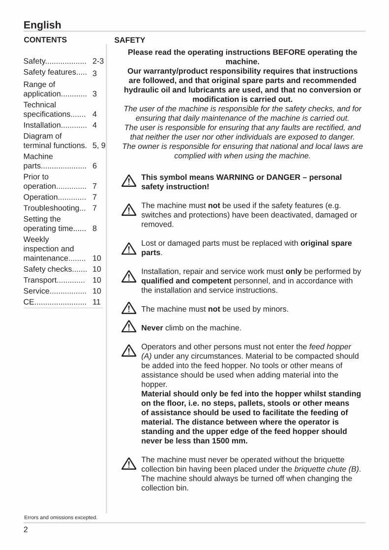
This symbol means WARNING or DANGER – personal safety instruction!
The machine must not be used if the safety features (e.g. switches and protections) have been deactivated, damaged or removed. Lost or damaged parts must be replaced with original spare parts. Installation, repair and service work must only be performed by qualifi ed and competent personnel, and in accordance with the installation and service instructions.
The machine must not be used by minors.
Never climb on the machine.
Operators and other persons must not enter the feed hopper (A) under any circumstances. Material to be compacted should be added into the feed hopper. No tools or other means of assistance should be used when adding material into the hopper. Material should only be fed into the hopper whilst standing on the fl oor, i.e. no steps, pallets, stools or other means of assistance should be used to facilitate the feeding of material. The distance between where the operator is standing and the upper edge of the feed hopper should never be less than 1500 mm.
The machine must never be operated without the briquette collection bin having been placed under the briquette chute (B). The machine should always be turned off when changing the collection bin.
English
Please read the operating instructions BEFORE operating the machine.
Our warranty/product responsibility requires that instructions are followed, and that original spare parts and recommended
hydraulic oil and lubricants are used, and that no conversion or modifi cation is carried out.
The user of the machine is responsible for the safety checks, and for ensuring that daily maintenance of the machine is carried out.
The user is responsible for ensuring that any faults are rectifi ed, and that neither the user nor other individuals are exposed to danger.
The owner is responsible for ensuring that national and local laws are complied with when using the machine.
SAFETY
Safety................... 2-3Safety features..... 3Range of application............ 3Technical specifi cations....... 4Installation............ 4Diagram of terminal functions. 5, 9Machine parts..................... 6Prior to operation.............. 7Operation............. 7Troubleshooting... 7Setting the operating time...... 8Weekly inspection and maintenance........ 10Safety checks....... 10Transport............. 10Service................. 10CE........................ 11
CONTENTS
Errors and omissions excepted.

3
SAFETY FEATURES The machine is equipped with the following safety features: Caps/protective covers restrict access to dangerous moving parts. The machine is also equipped with two emergency stops (E), as well as a main switch (D) that can be padlocked to prevent unauthorised use, e.g. during service, clea-ning and maintenance, or when removing any material that has become trapped.
RANGE OF APPLICATION The machine is essentially designed to compact corrugated cardboard. However, other types of material can be compacted in the briquetting press, subject to the approval of the manufacturer. The machine must only be used in areas that have a roof, protection against wind, and normal lighting.
Materials that are flammable or of an explosive nature (e.g. pressurised containers or the like) which, when exposed to pressure or sparks, could cause damage, fi re or an explosion, must not be compacted in the machine. The same also applies to compact paper material (e.g. newspapers, brochures, data lists, books, etc), metal materials, glass, wood materials, liquids, foodstuffs, plastics, rubber, minerals, chemicals and rubber, none of which should be compacted in the machine.
The machine must only be used if all the cover plates and caps/protective covers are in place and correctly fi tted. The electrical box (C) must be closed when the machine is connected to the mains.
No work (service, repairs, disassembly, maintenance, etc.) should be carried out on the machine unless the main power switch (D) is padlocked in the off position. Always turn the main power switch off before disconnecting the mains cable for any reason.
The machine and the area surrounding it should be kept clean and free of foreign objects.
The machine is not intended to be placed in areas where there is a high risk of explosion.
English

4
TECHNICAL SPECIFICATIONS
EnglishINSTALLATION There should be at least 1 metre of open space around the machine.The clearance height where the machine is to be placed should be at least 30 centimetres (see Technical specifi cations).
(Illustrations referred to in the text appear on the next two pages.)
Electrical installation (should be carried out by a qualifi ed electrician) Check the motor’s (H) direction of rotation, as follows:Activating manual mode (on the terminal):- Turn the main power switch (D) onTerminal text“BRICKMANREADY TO START”
- Press F4, twice
“Main menu” - Press the down arrow until the cursor is on “Manual mode”
- Press Enter “Manual mode” - Move the cursor to “Feed plate”
- Press Enter “F1 FEED PLATE FOR-WARD”“F2: FEED PLATE BACK”
- Press and hold F1 for 4 seconds
1. Make sure that the feed plate (I) has moved towards the cutting blades (R).
2. If no movement has occurred: turn the main power switch off and disconnect the mains cable.
3. Change the incoming phases.- Press F4 several times until "BRICKMAN READY TO START" is displayed.
Fit the briquette chute (B) (it is normally placed in the feed hopper (A) during transport) by fi rst removing the protective cover/cap (F) or cover plates on the machine. Secure the briquette chute using the four bolts and the springs (G). Replace the cover plate(s)/cap(s).Remove any transport protections between the hydraulic pump (X) and the tank.
If fi tted, activate the guillotine's (4) optional lubrication cans (J).
(Brickman 900)
GENERAL DATAA 2470 mm B 2010 mmC 585 mm D 1350 mmE 1500 mm F 1870 mmG 5710 mm H 1355 mmI 695 mm J 1350 mm
K 950 mm L 1180 mmM 1570 mm N 265 mmO 1035 mm P 230 mmQ 930 mm R 535 mmS 840 mm T 1960 mmU 1300 mm V 1155 mm
Machine weight: 3200 kgDimensions:
Height: 2470 mmWidth: 5710 mmDepth: 1960 mmFeed hopper:Depth: 930 mmWidth: 1300 mmVolume: 1.5 m³Colour: RAL 2001
(orange)Noise level: 68 dB (A)
ELECTRICAL DATAOperating voltage: 3x400VControl voltage 24V (DC)Mains connection:
5-pin Euro plug (32A)
Fuse: 25A (delay action)Electric motor: 7.5 kWProtection class: IP 55
HYDRAULIC DATA:Working pressure: max 200 barPress force: 250 kNCompaction pressure/cm² 62 kgCycle time, total: 29 sVolume of oil: 160 litresRecommended oil:+5°C to +60°C:Statoil HVXA 32, or equivalent
Below +5°CA special oil or a heater may be necessary at lower temperatures.
5
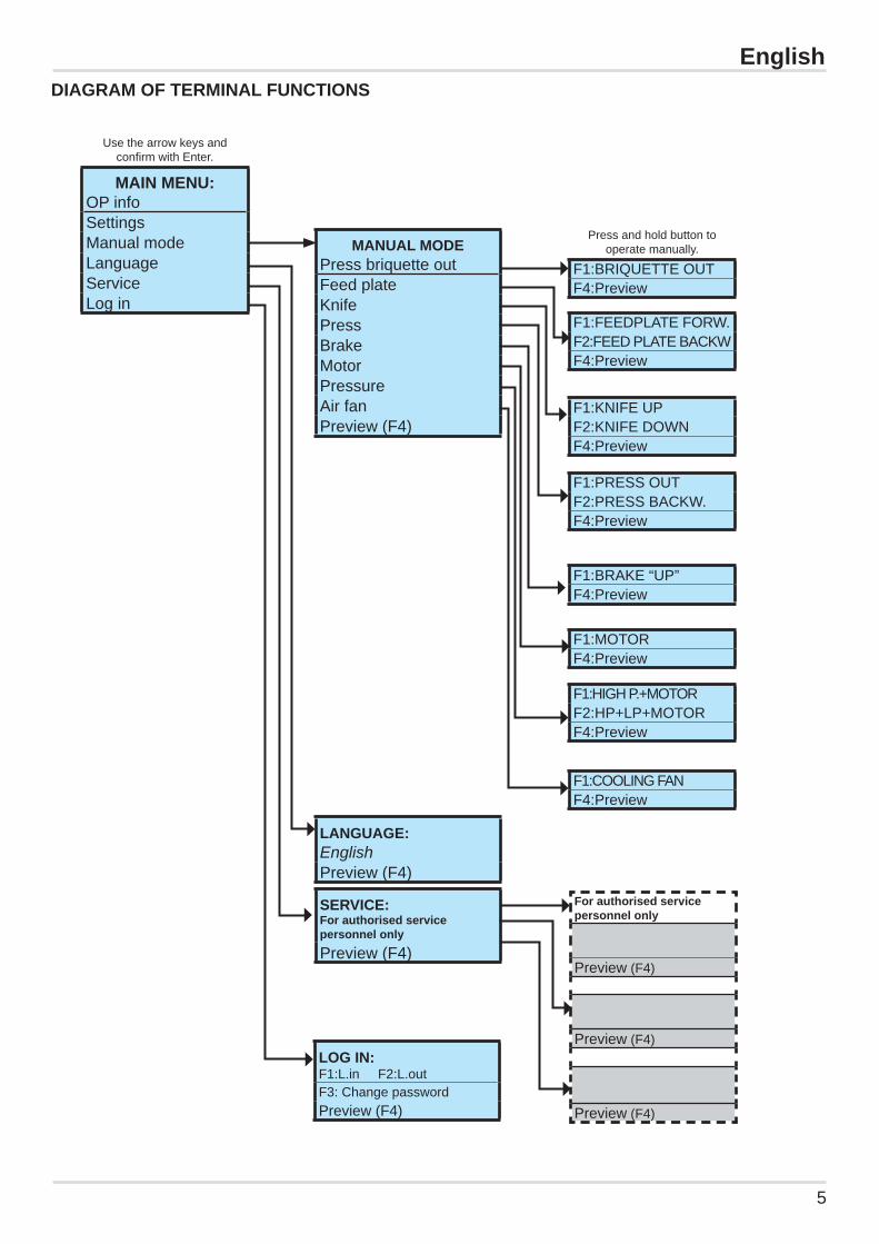
EnglishDIAGRAM OF TERMINAL FUNCTIONS
Use the arrow keys and confi rm with Enter.
MAIN MENU:OP infoSettingsManual modeLanguageServiceLog in
Press and hold button to operate manually.
F1:BRIQUETTE OUTF4:Preview
F1:FEEDPLATE FORW.F2:FEED PLATE BACKWF4:Preview
F1:KNIFE UPF2:KNIFE DOWNF4:Preview
F1:PRESS OUTF2:PRESS BACKW.F4:Preview
F1:HIGH P.+MOTORF2:HP+LP+MOTORF4:Preview
F1:COOLING FANF4:Preview
F1:BRAKE “UP”F4:Preview
F1:MOTORF4:Preview
LANGUAGE:EnglishPreview (F4)
SERVICE:For authorised service personnel onlyPreview (F4)
For authorised service personnel only
Preview (F4)
Preview (F4)
Preview (F4)
LOG IN:F1:L.in F2:L.outF3: Change passwordPreview (F4)
MANUAL MODEPress briquette outFeed plateKnifePressBrakeMotorPressureAir fanPreview (F4)
6
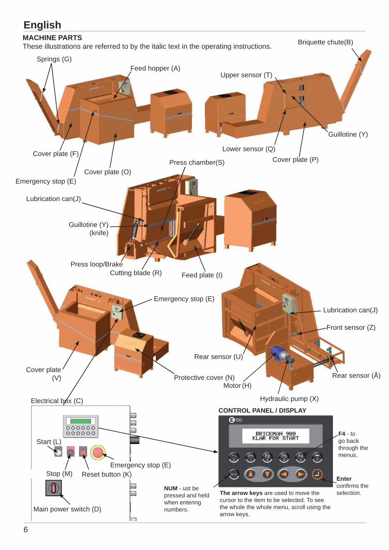
EnglishMACHINE PARTSThese illustrations are referred to by the italic text in the operating instructions.
Emergency stop (E)Stop (M)
Start (L)
Main power switch (D)
Reset button (K)
Electrical box (C)CONTROL PANEL / DISPLAY
Enter confi rms the selection.
F4 - to go back through the menus.
NUM - ust be pressed and held when entering numbers.
The arrow keys are used to move the cursor to the item to be selected. To see the whole the whole menu, scroll using the arrow keys.
Briquette chute(B)
Press loop/Brake
Guillotine (Y) (knife)
Lubrication can(J)
Lubrication can(J)
Front sensor (Z)
Rear sensor (Å)
Cutting blade (R) Feed plate (I)
Emergency stop (E)
Emergency stop (E)
Feed hopper (A)
Protective cover (N)
Rear sensor (U)
Cover plate (V)
Cover plate (O)
Cover plate (P)
Upper sensor (T)
Guillotine (Y)
Lower sensor (Q)
Press chamber(S)
Motor (H)
Hydraulic pump (X)
Springs (G)
Cover plate (F)

7
EnglishPRIOR TO OPERATIONEnsure that the main power switch (D) is turned off. Make sure that there are no foreign objects in the feed hopper (A) or on or around the machine. Ensure that the collection bin has been placed under the briquette chute (B). Turn the main power switch on. Press the Reset button (K) The machine is now ready for use.
OPERATION Press the start button (L). Place material into the feed hopper (A). The machine operates for a pre-set period of time and then stops. When delivered, the machine is normally set for an operating time of 2 minutes. (The operating time can be changed – see the section “Setting the operating time”.)The machine can also be stopped by pressing the stop button (M). The machine will stop once an operation cycle has been completed, i.e. once it is in the home position, ready for new material to be fed in. If necessary, the machine can be stopped by using either of the two emergency stops (E). Rectify the situation that caused the emergency stop to be used. Reset the emergency stop by pulling it out, then press the reset button (K).
FAULT FINDING (messages on the terminal screen)Check the terminal located on the machine’s electrical box (C) for any error messages.If the screen is empty/there is no text:Turn the main power switch (D) off, disconnect the mains cable and open the electrical box. Check the automatic fuses in the electrical box. Check the fuses for the machine’s power supply in the building’s distribution box.Close the electrical box. Check that the mains cable is not damaged.Reconnect the mains cable and turn the main power switch back on. If the reset button (K) is fl ashing:Check the terminal screen for any messages. In the event of an alarm or loss of power, the machine must be reset by pressing the reset button.
Terminal messages“Ready to start” – The machine is reset and ready to start.“Emergency Stop active” – An emergency stop button (E) is pressed in. “Emergency Stop” – An emergency stop button (E) has been pressed but the machine has not been reset. “Preheating oil” – The oil is being heated. The machine will not run until the correct temperature has been reached.“Oiltemp OK” – The oil has reached the correct temperature. Reset is not required."Oil overheated" – The temperature of the hydraulic oil is too high. The machine will not reset or start until the oil has cooled down and the message “Has been overheated” is displayed. “Has been overheated” – The temperature of the hydraulic oil has been too hot but is now back down to an acceptable level, and the machine can be started without being reset.“Low” – The oil level in the hydraulic tank is too low. Check for any oil leak. Repair the leak and refi ll with oil. The message “Oil level” is displayed. Reset by pressing the reset button (K). “Oil level” – The oil level in the hydraulic tank has been too low or is close to the “too-low” level.Reset by pressing the Reset button (K). “Motor protection” – The electrical motor’s overload protection has been activated (the motor is overloaded). Wait for a few minutes so that the overload protection can reset itself. Reset by pressing the reset button (K).

8
“Fault on B317” – Pressure sensor fault. Contact authorised service personnel.“Important. Change PLC battery!” - The battery in the PLC must be changed. Contact authorised service personnel immediately.“Book service” – The machine requires servicing. Contact authorised service personnel.
SETTING THE OPERATING TIME (on the terminal):Terminal text “BRICKMANREADY TO START”
- Press F4, twice
“Main menu” - Press the down arrow until the cursor is on “Settings” - Press Enter
“Settings” - Scroll down until the cursor is on “Operating time at start”- Press Enter
“Operating timeTime control” - Move the cursor to YES (to set the number of minutes)
- To change to NO (continuous operation), press Enter - Scroll the cursor to XX in “Operating time xx minutes”- Press and hold the NUM key and enter the desired operating time in minutes- Press Enter to confi rm the selection
- Press F4 several times until "BRICKMAN 300, READY TO START" is displayed.
“Knife down” – The guillotine (Y) has not reached the lower sensor (Q). Press the reset button (K). Start the machine using the start button (L). Run the machine until the guillotine reaches its upper position. Stop the machine in this position using emergency stop (E). Turn the main power switch (D) off and disconnect the plug from the mains. Clear the press chamber (S) of material.“Knife up” – The guillotine (Y) has not reached the upper sensor (T). Remove the cover plate (P) on the rear of the machine in order to access the guillotine (Y). Check that no material has accumulated on the guillotine. Check the function and position of the upper sensor. “Feed plate” – The feed plate (I) has not reached the rear sensor (U). Remove the cover plate (V) on the feed plate. Check that no material has accumulated at the rear of the feed plate. Check the function and position of the rear sensor. “Press” – The press cylinder has not reached its forward position. Press the reset button (K). Start the machine using the start button (L). Run the machine until the press cylinder reaches its rear position. Stop the machine in this position using emergency stop (E). Turn the main power switch (D) off and disconnect the machine’s power cable. Secure the main power switch using a padlock. Clear the press chamber (S) of material.
EnglishWhen cleaning, all power to the machine should be turned off and the main power switch (D) should be secured with a padlock. A notice informing people that servicing is in progress should be hung on the control panel.Always use protective gloves and appropriate tools when cleaning the space in and around the guillotine.
0OFF
Also clean around the front (Z) and rear (Å) sensors.
9
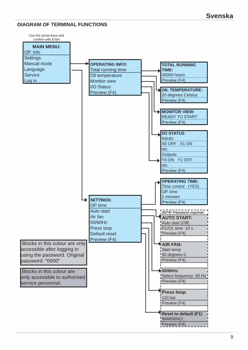
DIAGRAM OF TERMINAL FUNCTIONSSvenska
Use the arrow keys and confi rm with Enter
MAIN MENU:OP. infoSettingsManual modeLanguageServiceLog in
TOTAL RUNNING TIME:00000 hoursPreview (F4)
OIL TEMPERATURE:20 degrees CelsiusPreview (F4)
MONITOR VIEW:READY TO STARTPreview (F4)
I/O STATUSInputs:X0 OFF X1 ONetc.Outputs:Y0 ON Y1 OFFetc.Preview (F4)
OPERATING TIME:Time control (YES)OP. time 2 minutesPreview (F4)
NOTE! Password required:AUTO START:Auto start (Off)FC/UL time 10 sPreview (F4)
AIR FAN:Start temp. 50 degrees CPreview (F4)
50/60Hz:Select frequency 50 HzPreview (F4)
Press loop:110 barPreview (F4)
Reset to default (F1)WARNING!Preview (F4)
OPERATING INFO:Total running timeOil temperatureMonitor viewI/O StatusPreview (F4)
SETTINGS:OP timeAuto startAir fan50/60HzPress loopDefault resetPreview (F4)
Blocks in this colour are only accessible after logging in using the password. Original password: "0000"
Blocks in this colour are only accessible to authorised service personnel.
10
English
NOTE! Always padlock the main power switch (D) during inspection and mainte-nance, service work and the removal of trapped waste, etc.
WEEKLY INSPECTION AND MAINTENANCE
Clean the machine and the area around it. Ensure that there are no foreign objects on the ma-chine. Ensure that there are no signs of damage on the machine. Remove the cap (N). Vacuum the hydraulic assembly. Make sure that there are no oil leaks. If a fan is fi tted: Before lifting off the cap, disconnect the connector in the electrical box (C) that con-nects the fan in the cap above the hydraulic assembly. Remove the cover plate (O) and clean out any material that may have got onto the wrong side of the feed plate (I).Remove the cover plate (P) and clean out any material that may have got onto the guillotine (Y).
Check that the machine has no oil leaks and that all bolts and nuts are tightened. Check that no parts are loose or damaged.
SAFETY CHECKSRegularly check that the cover plates are intact and in place. Also, be sure to regularly check the function of the two emergency stops (E). Contact authorised service personnel immediately if the emergency stops do not work. If any fault is found in the functions listed above, the machine must not be used until it has been repaired by authorised service personnel.
Service and repairs must only be carried out by qualifi ed and competent personnel, and in accord-ance with the machine manufacturer’s instructions.
SERVICEThe fi rst service should be carried out within 500 hours of operation. Subsequent service should be carried out at 500-1000 hour intervals or once a year. These intervals may vary depending on the surrounding environment and the material to be compacted by the machine, and should there-fore be discussed with the manufacturer’s authorised service personnel.
Oil change: Contact the local authorities for advice regarding how to reduce environmental impact when dealing with residual oil.
0OFF

AB ORWAK Box 58 SE-576 22 Sävsjö, Sweden Tel: 46-382-15700 Fax: 46-382-10607
11
to which this declaration relates is in EC conformity with the following Standards or other normative documents following the provisions of Directive
declares under its sole responsibility that the product
model:..................................
with serial number:.................
Product Manager and compiler of technical documentation
EC DECLARATION OF CONFORMITY
2006/42/EEC (Machinery Directive)2004/108/EEC (EMC Directive)
73/23/EEC, 93/68/EEC, 2006/96/EC (Low Voltage Directive)
SS-EN 60204-1 SS-EN ISO13850 SS-EN ISO12100-1 SS-EN ISO12100-2 SS-EN ISO13857 SS-EN 982 EN 954-1
We
Ljungby 2010-01-01
Brickman 900

Orwak is a world leader in compaction and baling solu-tions for solid waste material at source. We develop, manufacture and market a comprehensive range of waste compactors, baling systems and “Brickman” bri-quette presses for recyclable materials that make waste management more profi table. We also o er fully auto-matic balers for recyclable materials through our sub-sidiary Presona. This is where Orwak’s unequalled
technology, expertise and service support make all the di erence. When you partner with Orwak, you also gain access to the vast experience we have built up over the last 35 years. Orwak is wholly owned by the Norwegian company Tomra, a leading global player in providing integrated solutions for recovering and recycling used packaging.
Leader in compaction
and baling solutions