ortop modular robot v3.0 arm assembly modular robot arm assembly v3.0 – 6/22/2010 page 2 assembly...
TRANSCRIPT

ORTOP Modular Robot Arm Assembly v3.0 – 6/22/2010 Page 1
ORTOP Modular Robot v3.0
Arm Assembly Base Plate Assembly Parts Needed: Arm Assembly BAG 1
2 – Socket Head Cap Screw, 1-1/4" 2 – Socket Head Cap Screw, 1/2" 2 – Button Head Cap Screw, 3/8" 6 – Nuts 1 – Gear Hub Spacer 1 – Flat Building Plate 1 – Single Servo Motor Bracket 1 – Servo
ORTOP Modular Robot Arm Assembly v3.0 – 6/22/2010 Page 2
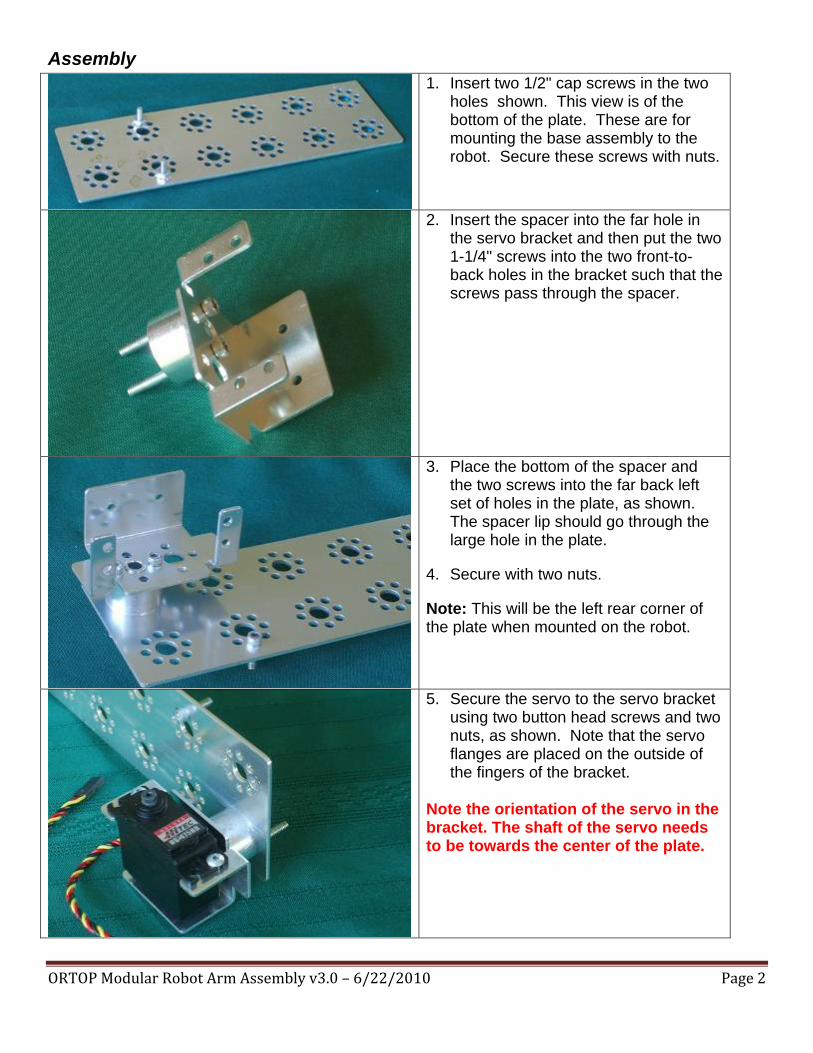
Assembly 1. Insert two 1/2" cap screws in the two
holes shown. This view is of the bottom of the plate. These are for mounting the base assembly to the robot. Secure these screws with nuts.
2. Insert the spacer into the far hole in the servo bracket and then put the two 1-1/4" screws into the two front-to-back holes in the bracket such that the screws pass through the spacer.
3. Place the bottom of the spacer and the two screws into the far back left set of holes in the plate, as shown. The spacer lip should go through the large hole in the plate.
4. Secure with two nuts.
Note: This will be the left rear corner of the plate when mounted on the robot.
5. Secure the servo to the servo bracket using two button head screws and two nuts, as shown. Note that the servo flanges are placed on the outside of the fingers of the bracket.
Note the orientation of the servo in the bracket. The shaft of the servo needs to be towards the center of the plate.

ORTOP Modular Robot Arm Assembly v3.0 – 6/22/2010 Page 3
Parts Needed: 1 – Plate and Servo Assembly Arm Assembly BAG 2
2 – Socket Head Cap Screw, 1-1/4” 2 – Nuts 1 – Gear Hub Spacer 1 – 32 mm Channel

ORTOP Modular Robot Arm Assembly v3.0 – 6/22/2010 Page 4
Assembly 6. Insert the spacer in the large hole in
the bottom of the channel.
7. Place two 1-1/4" screws through the two holes as shown. The screws will be in the holes closest to the arms of the C channel.
8. Secure this assembly to the middle two holes on the front end of the flat plate, opposite the servo, using two nuts.
Note that the spacer does not fit into a large hole in the plate. It is centered between two large holes.
ORTOP Modular Robot Arm Assembly v3.0 – 6/22/2010 Page 5
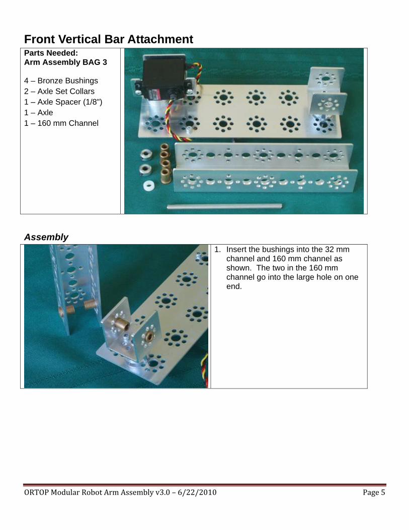
Front Vertical Bar Attachment Parts Needed: Arm Assembly BAG 3 4 – Bronze Bushings 2 – Axle Set Collars 1 – Axle Spacer (1/8") 1 – Axle 1 – 160 mm Channel
Assembly 1. Insert the bushings into the 32 mm
channel and 160 mm channel as shown. The two in the 160 mm channel go into the large hole on one end.

ORTOP Modular Robot Arm Assembly v3.0 – 6/22/2010 Page 6
2. Slide the axle through the four bushings with a 1/8" plastic spacer between the two inner bushings. Slide the collars onto the ends of the axle.
3. Position one collar about 1/4" from the end of the axle and tighten the set screw.
4. Hold the second collar against the bushing with gentle pressure (too much pressure will cause the bar to bind as it pivots) and tighten its set screw.
5. Make sure the set screws are screwed against the flat part of the axle.
Rear Vertical Bar Attachment Parts Needed: 1 – 160 mm Channel 2 – Button Head Cap
Screws 2 – Nuts 1 – Servo Horn 1 – Black 3/8" Phillips
head screw

ORTOP Modular Robot Arm Assembly v3.0 – 6/22/2010 Page 7
Assembly 6. Place the servo horn on the outside of
the end set of holes in the channel as shown. Secure with two button head screws and nuts.
Note: these nuts must be very tight. They have a tendency to come loose and they cannot be retightened when the robot is assembled
7. Slide the splined hole in the servo horn over the splined shaft on the end of the servo.
Note: before screwing in the horn, carefully rotate the servo shaft to find the endpoints of the servo movement (it has ~200 degrees of rotation). Remove and replace the horn in a different rotational position until the arm can swing through 180 degrees from front to back, with the base plate as horizontal reference.
8. Insert and tighten the self-tapping screw into the servo shaft through the hole in the servo horn. Be very careful not to over-tighten this screw.

ORTOP Modular Robot Arm Assembly v3.0 – 6/22/2010 Page 8
Top Bar Attachment Parts Needed: Arm Assembly BAG 5
1 – 288 mm Channel 4 – Axle Set Collars 1 – 3/8" Axle Spacer 1 – 1/8" Axle Spacer 8 – Bronze Bushings 2 – Axles
Assembly 1. Slide one bushing and one collar on
each axle. Position the collar about 1/4" from the end and tighten the set screw onto the flat part of the axle.
2. Slide the axles through the end hole and 10th hole in the channel as shown. The end hole represents the rear of the arm.
3. Add a second bushing, plastic spacer and third bushing, as shown, to each axle. The end axle uses the 1/8" spacer while the other axle uses the 3/8" spacer.
111000ttthhh HHHooollleee fffrrrooommm llleeefffttt

ORTOP Modular Robot Arm Assembly v3.0 – 6/22/2010 Page 9
4. Slide the two vertical bars from the base plate assembly onto the uncollared end two axles, with the rear bar using the axle on the end (rear) of the 288 mm channel.
Note the base plate assembly is upside down in this illustration.
5. Slide the last bushing over each axle and slide a collar onto each axle.
6. Tighten the collar set screws onto the flat of the axle, using gentle pressure to keep the collar against the bushing.
RRReeeaaarrr FFFrrrooonnnttt
BBBaaassseee PPPlllaaattteee AAAsssssseeemmmbbblllyyy

ORTOP Modular Robot Arm Assembly v3.0 – 6/22/2010 Page 10
Arm Assembly (cont)
Right Pincer Assembly Parts Needed: Arm Assembly BAG 6
2 – Socket Head Cap Screws, 1/2" 2 – Socket Head Cap Screws, 5/16" 1 – Socket Head Cap Screws, 1-1/4" 5 – 6-32 Nuts 1 – 144mm Angle 1 – Flat Bracket 1 – L Bracket 1 – Wide Balloon Tire 1 – Wide Rim w/ Cross

ORTOP Modular Robot Arm Assembly v3.0 – 6/22/2010 Page 11
Assembly 1. Attach the flat bracket to the L
bracket using two 5/16" screws and nuts. Attach the L bracket to the 144 mm angle with the 1/2" screws.
2. If the tire is not mounted on the rim, do so now.
3. Carefully screw the 1-1/4" screw all the way through the center of the large wheel. Once you get to the smooth portion of the screw you will need to apply a bit of pressure while turning to keep the screw moving.
4. Attach the tire to the second hole from the end of the angle. Note the tire goes through from the side of the angle with a flat portion.
Note: Do not over tighten the screw or you can damage the wheel.
ORTOP Modular Robot Arm Assembly v3.0 – 6/22/2010 Page 12
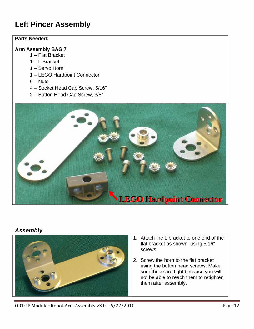
Left Pincer Assembly Parts Needed:
Arm Assembly BAG 7 1 – Flat Bracket 1 – L Bracket 1 – Servo Horn 1 – LEGO Hardpoint Connector 6 – Nuts 4 – Socket Head Cap Screw, 5/16" 2 – Button Head Cap Screw, 3/8"
Assembly 1. Attach the L bracket to one end of the
flat bracket as shown, using 5/16" screws.
2. Screw the horn to the flat bracket using the button head screws. Make sure these are tight because you will not be able to reach them to retighten them after assembly.
LLLEEEGGGOOO HHHaaarrrdddpppoooiiinnnttt CCCooonnnnnneeeccctttooorrr

ORTOP Modular Robot Arm Assembly v3.0 – 6/22/2010 Page 13
3. Screw the hard point connector to the L bracket as shown using 5/16" screws.
Parts Needed:
Arm Assembly BAG 8
1 – Lego Angle Beam 3 – Lego Friction Pegs 2 – Lego O Rings 1 – Lego Small Wide Tire and Hub
ORTOP Modular Robot Arm Assembly v3.0 – 6/22/2010 Page 14
Assembly
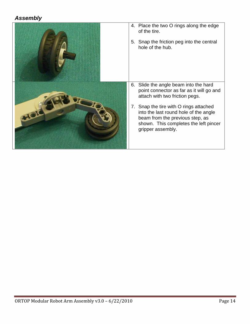
4. Place the two O rings along the edge of the tire.
5. Snap the friction peg into the central hole of the hub.
6. Slide the angle beam into the hard point connector as far as it will go and attach with two friction pegs.
7. Snap the tire with O rings attached into the last round hole of the angle beam from the previous step, as shown. This completes the left pincer gripper assembly.

ORTOP Modular Robot Arm Assembly v3.0 – 6/22/2010 Page 15
Parts Needed:
Arm Assembly BAG 9
1 – Flat Bracket 1 – Servo Bracket 1 – Servo 4 – Nuts 2 – Socket Head Cap Screw, 5/16" 2 – Button Head Cap Screw, 3/8"

ORTOP Modular Robot Arm Assembly v3.0 – 6/22/2010 Page 16
Assembly 8. Attach the servo bracket to one end of
the flat bracket as shown, using 5/16" screws.
9. Screw the servo to the servo bracket using the button head screws. Make sure the servo flanges are on the outside of the bracket. This completes the left pincer servo assembly.
Note: Do not over tighten these screws or you may damage the servo.

ORTOP Modular Robot Arm Assembly v3.0 – 6/22/2010 Page 17
Installing Left and Right Pincers Parts Needed: Arm Assembly BAG 10 1 – Right Pincer
Assembly 1 – Left Pincer Servo
Assembly 1 – Left Pincer Gripper
Assembly 4 – Socket Head Cap
Screw, 5/16" 4 – 6-32 Nuts 1 – 3/8" self-tapping
screw
Assembly
1. Attach the right pincer to the top bar at the end, using two 5/16" screws. It is attached to the right side of the top bar, as shown.

ORTOP Modular Robot Arm Assembly v3.0 – 6/22/2010 Page 18
2. Attach the left pincer servo assembly to the top bar on the other side from the right pincer (on the left side). (The right pincer is removed in this illustration for clarity.)
3. Insert the servo horn of the left pincer assembly onto the servo shaft. Before screwing in the self-tapping screw, make sure the range of motion of the servo is such that, at one end of its range, the arm is at about 90 degrees to the top bar. This position is shown in the illustration.
4. Screw in the self-tapping screw into the servo shaft, being careful not to over-tighten.
5. Again, the right pincer is removed in this illustration for clarity.

ORTOP Modular Robot Arm Assembly v3.0 – 6/22/2010 Page 19
6. This shows both pincers attached to the top arm. The view is upside down.

ORTOP Modular Robot Arm Assembly v3.0 – 6/22/2010 Page 20
Installing Arm Return Bracket and Servo Extension Parts Needed: 1 – Arm Assembly Arm Assembly BAG 11
4 – Button Head Cap Screw, 3/8"
4 – 6-32 Nuts 1 – Flat Bracket 1 – L Bracket 1 – Servo Extension
cable
Assembly 1. Turn over the arm.
2. Slip the pincer servo wire under the front pivot axle.
3. Slip the female (hollow) end of the servo extension wire under the rear pivot axle.
4. Connect the servo extension wire to the pincer servo wire making sure the yellow wires line up as shown.

ORTOP Modular Robot Arm Assembly v3.0 – 6/22/2010 Page 21
5. Attach the L Bracket to the Plate using two button head screws as shown. This is the Arm Return Bracket.
6. Attach the arm return bracket to the rear vertical bar using two button head screws as shown.
Completed Arm Assembly