orion skyquest xtg goto dobsonians€¦ · · 2015-03-16instruction manual in 388 rev. d 06/13...
TRANSCRIPT
i n s t r u c t i o n M a n u a l
IN 388 Rev. D 06/13
orion® skyQuest™ Xtg Goto Dobsonians
#10134 XT8g, #10135 XT10g, #10136 XT12g
Customer Support: www.OrionTelescopes.com/contactusCorporate Offices:89 Hangar Way, Watsonville CA 95076 - USA
Providing Exceptional Consumer Optical Products Since 1975

2
Figure 1. Overview of SkyQuest XTg Dobsonian (12" shown)
Navigation knob
Altitude motor housing
12.5mm Illuminated Plössl 1.25" eyepiece
Eyepiece rack
Dobsonian base
Polyethylene foam dust guard
EZ Finder II
28mm DeepView 2" eyepiece
2" Dual-speed Crayford focuser
Optical tube
Handle
Handle
Tube connecting knob
GoTo hand controller
Azimuth motor housing (not shown)
3
Congratulations on your purchase of an Orion SkyQuest XTg GoTo Dobsonian. It is an observer’s dream telescope, offering quality diffraction-limited optics; a stylish, easy-to-setup base outfitted with automated, computerized GoTo technology; and a sturdy design. This high-performance astronomical instrument will provide dazzling views of celestial objects, yet be transportable and wonderfully easy to use.
With the alt-azimuth GoTo system, you simply select an object from the 42,900 object database and the telescope will take you there with the push of a couple of buttons. Searching for objects is a thing of the past, as the GoTo servo motors and computerized database find them for you in seconds, then track them while you enjoy the view! Deluxe features such as a 2" dual-speed Crayford focuser, enhanced-reflectivity mirror coatings, and full accessory assortment provide everything you need to enjoy your journey through the universe.
Please read these instructions thoroughly before beginning assembly and subsequent use of the telescope.
1. unpackingThe telescope is packed in two boxes, one containing the opti-cal tube assembly and accessories, another containing the unassembled Dobsonian base. The 12" model has a third box containing the primary mirror in its cell. Be careful unpacking the boxes. We recommend keeping the original packaging. In the event that the telescope needs to be shipped to another location, or returned to Orion for warranty repair, having the proper packaging will help ensure that your telescope will sur-vive the journey intact.
Before beginning assembly, unpack each box and confirm that all of the parts in the Parts List below are present. The parts are listed by the box they should arrive in, but some of the parts may be in different boxes than indicated below.
Be sure to check all boxes carefully, as some parts are small. If anything appears to be missing or broken, immedi-ately call Orion Customer Support (800-676-1343) or email [email protected] for assistance.
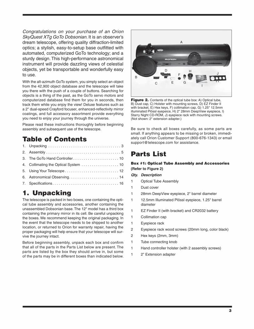
Parts listBox #1: optical tube assembly and accessories(Refer to Figure 2)
Qty. Description
1 Optical Tube Assembly
1 Dust cover
1 28mm DeepView eyepiece, 2" barrel diameter
1 12.5mm Illuminated Plössl eyepiece, 1.25" barrel diameter
1 EZ Finder II (with bracket) and CR2032 battery
1 Collimation cap
1 Eyepiece rack
2 Eyepiece rack wood screws (20mm long, color black)
2 Hex keys (2mm, 3mm)
1 Tube connecting knob
1 Hand controller holster (with 2 assembly screws)
1 2" Extension adapter
A
B
C
D
E
F
G
H
I
J
Figure 2. Contents of the optical tube box: A) Optical tube, B) Dust cap, C) Holster with mounting screws, D) EZ Finder II with bracket, E) Hex keys, F) collimation cap, G) 1.25" 12.5mm illuminated Plössl eyepeice, H) 2" 28mm DeepView eyepiece, I) Starry Night CD-ROM, J) eyepiece rack with mounting screws. (Not shown: 2" extension adapter.)
table of contents1. Unpacking . . . . . . . . . . . . . . . . . . . . . . . . . . . . . . . . . . . 3
2. Assembly . . . . . . . . . . . . . . . . . . . . . . . . . . . . . . . . . . . . 5
3. The GoTo Hand Controller . . . . . . . . . . . . . . . . . . . . . . 10
4. Collimating the Optical System . . . . . . . . . . . . . . . . . . 10
5. Using Your Telescope . . . . . . . . . . . . . . . . . . . . . . . . . . 12
6. Astronomical Observing. . . . . . . . . . . . . . . . . . . . . . . . 14
7. Specifications. . . . . . . . . . . . . . . . . . . . . . . . . . . . . . . . 16
4
Box #2: Dobsonian Base(Refer to Figures 3 and 4)
Qty. Description
1 Left side panel (with altitude motor pre-installed)
1 Right side panel
1 Front panel
2 Side braces (XT12g only, not shown)
1 Baseplate assembly (with azimuth motor pre-installed)
6 Base assembly wood screws (coarse thread, 47mm long) (Quantity 12 for XT12g)
8 Base assembly machine screws (fine thread, 60mm long) (Quantity 10 for XT12g)
8 Washers for base assembly machine screws (Quantity 10 for XT12g)
3 Handles
6 Handle mounting screws (hex head, 25mm long)
3 Hex keys (size 2mm, 4mm, 6mm)
3 Plastic feet
3 Feet wood screws (1" long)
1 Hand controller
1 Hand controller cable (coiled)
1 Azimuth motor connection cable
1 RS-232 computer cable
1 DC power cable
Box #3: Primary Mirror and cell (12" model only)Qty. Description
1 Primary mirror
1 Mirror cell
3 Collimation knobs
3 Nylon washers (3/4" outer diameter)
3 Springs
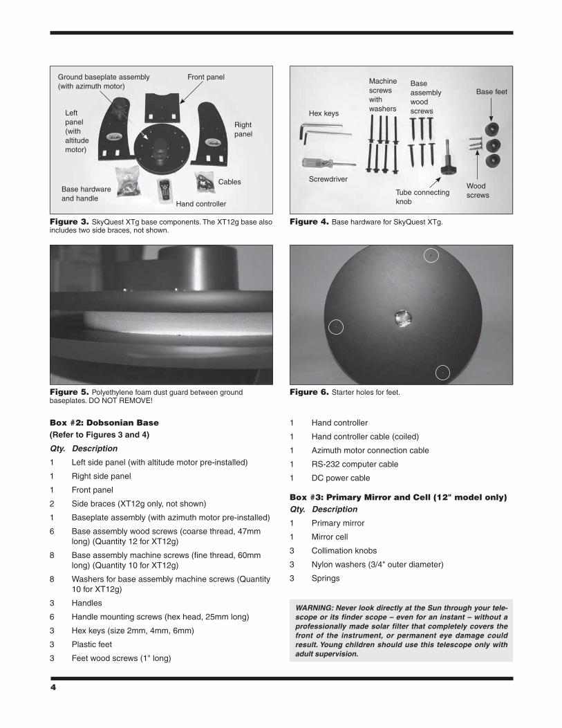
Figure 3. SkyQuest XTg base components. The XT12g base also includes two side braces, not shown.
Figure 5. Polyethylene foam dust guard between ground baseplates. DO NOT REMOVE!
Figure 6. Starter holes for feet.
Figure 4. Base hardware for SkyQuest XTg.
Left panel (with altitude motor)
Ground baseplate assembly (with azimuth motor)
Front panel
Right panel
Cables
Hand controller
Base hardware and handle
Screwdriver
Hex keys
Machine screws with washers
Base assembly wood screws
Tube connecting knob
Base feet
Wood screws
WARNING: Never look directly at the Sun through your tele-scope or its finder scope – even for an instant – without a professionally made solar filter that completely covers the front of the instrument, or permanent eye damage could result. Young children should use this telescope only with adult supervision.
5
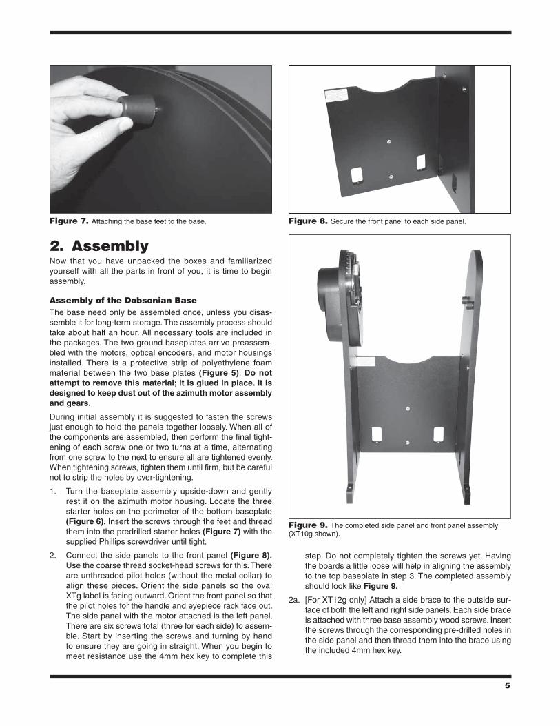
2. assemblyNow that you have unpacked the boxes and familiarized yourself with all the parts in front of you, it is time to begin assembly.
assembly of the Dobsonian BaseThe base need only be assembled once, unless you disas-semble it for long-term storage. The assembly process should take about half an hour. All necessary tools are included in the packages. The two ground baseplates arrive preassem-bled with the motors, optical encoders, and motor housings installed. There is a protective strip of polyethylene foam material between the two base plates (Figure 5). Do not attempt to remove this material; it is glued in place. It is designed to keep dust out of the azimuth motor assembly and gears.
During initial assembly it is suggested to fasten the screws just enough to hold the panels together loosely. When all of the components are assembled, then perform the final tight-ening of each screw one or two turns at a time, alternating from one screw to the next to ensure all are tightened evenly. When tightening screws, tighten them until firm, but be careful not to strip the holes by over-tightening.
1. Turn the baseplate assembly upside-down and gently rest it on the azimuth motor housing. Locate the three starter holes on the perimeter of the bottom baseplate (Figure 6). Insert the screws through the feet and thread them into the predrilled starter holes (Figure 7) with the supplied Phillips screwdriver until tight.
2. Connect the side panels to the front panel (Figure 8). Use the coarse thread socket-head screws for this. There are unthreaded pilot holes (without the metal collar) to align these pieces. Orient the side panels so the oval XTg label is facing outward. Orient the front panel so that the pilot holes for the handle and eyepiece rack face out. The side panel with the motor attached is the left panel. There are six screws total (three for each side) to assem-ble. Start by inserting the screws and turning by hand to ensure they are going in straight. When you begin to meet resistance use the 4mm hex key to complete this
step. Do not completely tighten the screws yet. Having the boards a little loose will help in aligning the assembly to the top baseplate in step 3. The completed assembly should look like Figure 9.
2a. [For XT12g only] Attach a side brace to the outside sur-face of both the left and right side panels. Each side brace is attached with three base assembly wood screws. Insert the screws through the corresponding pre-drilled holes in the side panel and then thread them into the brace using the included 4mm hex key.
Figure 7. Attaching the base feet to the base. Figure 8. Secure the front panel to each side panel.
Figure 9. The completed side panel and front panel assembly (XT10g shown).

6
3. Carefully position the assembled structure onto the top baseplate by aligning the holes in the cutouts of the front and side panels to the corresponding threaded metal col-lar inserts on the top baseplate (Figure 10). Insert the base assembly machine screws and tighten (Figure 11). Once this setup is complete you may firmly tighten the six base assembly screws installed in the previous step.
4. Attach the handles to the base. There are three handles, one for each side panel and one for the front panel. Use the 6mm hex key and the large socket head cap screws to install the handles. Each handle is the same so it does not matter which handle is used for any particular panel. Refer to Figure 1 for handle placement.
5. The aluminum eyepiece rack holds three 1.25" eyepieces and one 2" eyepiece in a convenient place on the base, within easy reach while you are observing. The eyepiece rack and its mounting screws can be found in the box with the optical tube. Attach the eyepiece rack on the front panel above the handle. There are two small pilot holes on the front panel approximately 6" apart. Thread the small Phillips-head screws into the holes but do
not tighten completely yet. Place the eyepiece rack on those screws using the wide holes on the rack and slide it downward so the narrow portion is under the screws. Now tighten the screws to secure the rack in place.
6. The XTg series includes a convenient holster to place the hand controller in when not in use. The holster installs on the altitude motor. Locate the two small pilot holes and attach the holster using the small screws until just tight. Do not over-tighten these screws!
7. Now install the azimuth motor connection cable. It is a flat cable that has an 8-pin RJ-45 plug on both ends. Plug one end into the jack on the azimuth motor housing on the top baseplate; plug the other end into the jack labeled AZ MOTOR on the altitude motor housing.
8. Finally, connect the GoTo hand controller. Plug the wide RJ-45 connector on the coiled hand controller cable into the corresponding port on the hand controller. Plug the smaller RJ-12 connector into the port labeled HC on the altitude motor housing.
assembly of the optical tube (Xt12g only)Both the XT8g and XT10g optical tubes arrive completely assembled from the factory. If you have one of these mod-els, you may skip ahead to the next section, “Connecting the Optical Tube to the Dobsonian Base”.
Due to its large size, and in order to prevent damage to the primary mirror in shipment, the 12" mirror is shipped in its cell separately from the optical tube. Once the primary mir-ror is installed into the telescope, there will be no need to remove the mirror except for occasional cleaning (see “Care & Maintenance”).
1. To install the mirror cell into the optical tube, the rear end ring attached to the lower section of the optical tube must first be removed. This is done by unthreading and remov-
Figure 10. Align the holes on the side panels with the threaded inserts in the baseplate.
Figure 11. Base assembly machine screws set in place, but not yet tightened.
Figure 12. To remove the rear end ring, unthread the six screws that connect it to the tube.
Threaded inserts
Cutout holes

7
ing the six Phillips-head screws that connect the end ring to the tube (Figure 12), and then pulling the end ring off the tube.
Warning: Once the rear end ring is removed from the tube, the raw edge of the tube itself will be exposed. Be careful not to cut or otherwise hurt yourself on the tubeís edge. Also, be careful not to pinch your fingers when re- attaching the assembled mirror cell onto the tube.
2. Next, assemble the rear end ring to the mirror cell. Find a clean, flat surface, and turn the mirror cell over so that the mirror is facing downwards. Place the three springs onto the three exposed threaded shafts (Figure 13). Lower the end ring onto the mirror cell so the threaded shafts pass through it, and the end ring rests on the springs (Figure 14). Add a nylon washer to each collima-tion knob and thread the collimation knobs through the end ring and onto the threaded shafts (Figure 15). Make sure the knobs have at least three full turns of engage-ment on the shafts. The mirror cell is now ready to be installed onto the lower tube section.
3. Assembling the end ring back onto the tube can be a bit tricky. This is because the large diameter and thin alumi-num of the tube will cause the tube to become somewhat out of round once the end ring is removed. To assemble the rear end ring (with mirror and mirror cell now con-nected) to the tube, stand the tube up vertically so the raw edge of the tube is facing upwards. Line up the threaded holes in the edge of the mirror cell end ring with the holes in the end of the tube. Then, lower the entire mirror cell assembly onto the tube. There may be a bulge in the perimeter of the tube which prevents the mirror cell from fully seating onto the tube (Figure 16). Press against this bulge, and the entire mirror cell should seat onto the tube. Now, replace the six Phillips-head screws that connect the rear end ring to the tube.
Figure 16. Locate the area of tube that is bulging out and preventing the end ring from fully seating.
Figure 13. Place the three springs on the exposed threaded shafts of the mirror cell.
SpringShaft
Figure 14. Lower the rear end ring onto the mirror cell so that the threaded shafts pass through the end ring, and the end ring rests on the springs.
Figure 15. Thread the collimation knobs, with nylon washers attached, through the rear end ring and onto the threaded shafts. Make sure the knobs have at least three full turns of engagement on the shafts.
Collimation knob
Nylon washer

8
connecting the optical tube to the Dobsonian BaseThe telescope is now assembled and ready to be placed into the Dobsonian base. The left altitude hub on the optical tube has a dovetail slot that slides into the altitude axis trunnion on the inside of the left side panel (Figure 17). We recommend orienting the trunnion such that the threaded hole for the tube securing knob is facing upward. Then the telescope tube can be cradled horizontally and just lowered into the base by gen-tly sliding tube’s dovetail altitude hub into the mating recep-tacle of the altitude trunnion on the base (Figure 18). (Get help lifting the tube in place if it is too heavy or unwieldy for you.) The tube should now be resting in a balanced, horizon-tal position in the base. Then just insert and tighten the tube connecting knob to secure the tube in place (Figure 19).
accessory installationNow that the base is assembled and the optical tube installed all that remains is to attach the EZ Finder II reflex sight and the eyepiece. These accessories can be found in a small box within the optical tube assembly box.
EZ Finder iiUsing the included dovetail mounting bracket, the EZ Finder II will slip neatly into the dovetail base preinstalled on your SkyQuest optical tube. The EZ Finder II arrives pre-installed in the mounting bracket. Just simply slide the dovetail mount-ing bracket into the telescope’s dovetail mounting base and tighten the thumbscrew on the base to secure the mounting bracket.
Before installing the EZ Finder II on the telescope, you’ll need to insert the included 3-volt lithium battery.
1. Insert a small, flat-blade screwdriver into the notch in the battery casing and gently pry it off (Figure 20).
2. Slide the CR2032 3V lithium battery under the retaining clip with the positive (+) side facing down (touching the clip).
3. Then press the battery casing back on.
Should the battery die, replacement CR2032 batteries are available at many stores where small batteries are sold.
Figure 17. The cast-metal dovetail trunnion on the left side panel of the base mates with the left side bearing of the telescope tube. Before mounting the tube on the base, turn the trunnion by hand so that the hole for the tube connecting knob is facing up.
Threaded hole for tube connecting knob
Figure 19. Secure the tube to the base with the tube connecting knob.
Figure 18. Hold the telescope tube as shown, with one hand on the rear end ring and the other cradling underneath the tube, gently lower the scope so the dovetail side bearing on the tube seats in the metal trunnion on the left side panel.
9
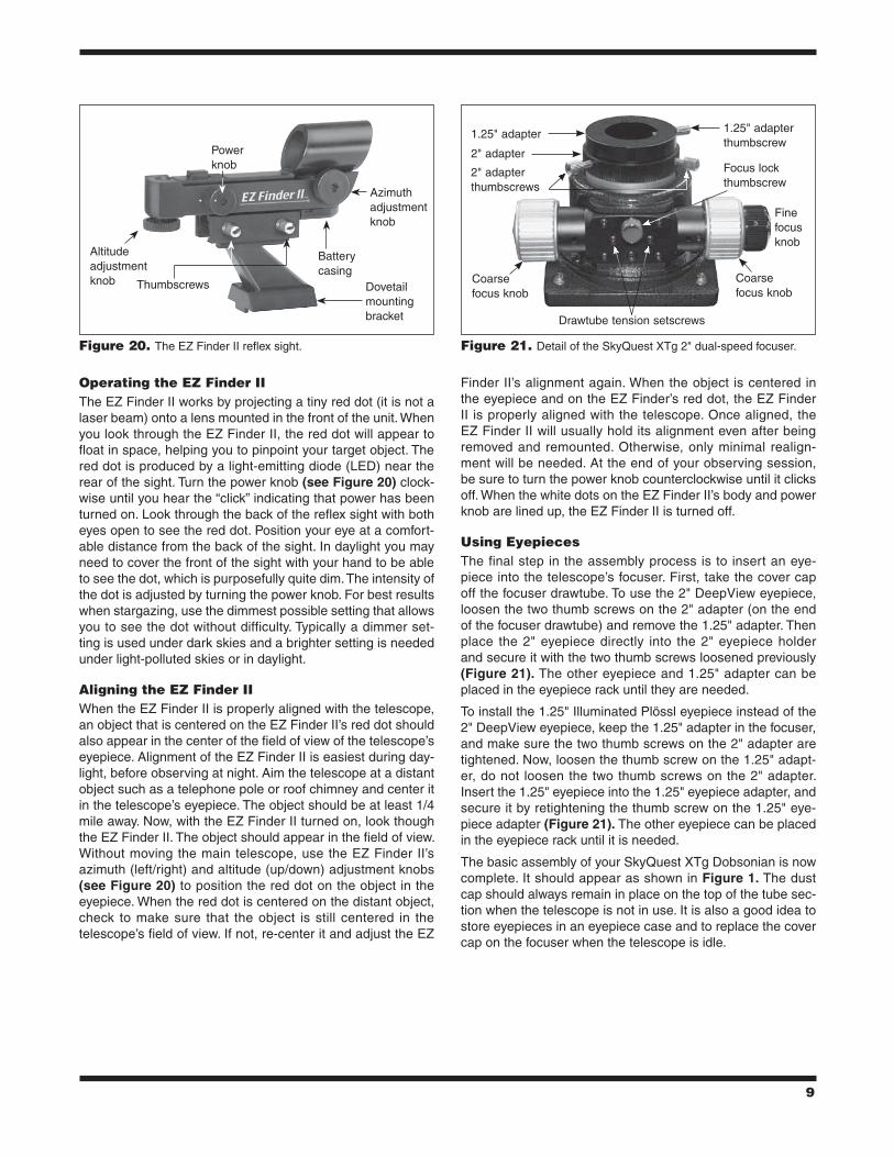
operating the EZ Finder iiThe EZ Finder II works by projecting a tiny red dot (it is not a laser beam) onto a lens mounted in the front of the unit. When you look through the EZ Finder II, the red dot will appear to float in space, helping you to pinpoint your target object. The red dot is produced by a light-emitting diode (LED) near the rear of the sight. Turn the power knob (see Figure 20) clock-wise until you hear the “click” indicating that power has been turned on. Look through the back of the reflex sight with both eyes open to see the red dot. Position your eye at a comfort-able distance from the back of the sight. In daylight you may need to cover the front of the sight with your hand to be able to see the dot, which is purposefully quite dim. The intensity of the dot is adjusted by turning the power knob. For best results when stargazing, use the dimmest possible setting that allows you to see the dot without difficulty. Typically a dimmer set-ting is used under dark skies and a brighter setting is needed under light-polluted skies or in daylight.
aligning the EZ Finder iiWhen the EZ Finder II is properly aligned with the telescope, an object that is centered on the EZ Finder II’s red dot should also appear in the center of the field of view of the telescope’s eyepiece. Alignment of the EZ Finder II is easiest during day-light, before observing at night. Aim the telescope at a distant object such as a telephone pole or roof chimney and center it in the telescope’s eyepiece. The object should be at least 1/4 mile away. Now, with the EZ Finder II turned on, look though the EZ Finder II. The object should appear in the field of view. Without moving the main telescope, use the EZ Finder II’s azimuth (left/right) and altitude (up/down) adjustment knobs (see Figure 20) to position the red dot on the object in the eyepiece. When the red dot is centered on the distant object, check to make sure that the object is still centered in the telescope’s field of view. If not, re-center it and adjust the EZ
Finder II’s alignment again. When the object is centered in the eyepiece and on the EZ Finder’s red dot, the EZ Finder II is properly aligned with the telescope. Once aligned, the EZ Finder II will usually hold its alignment even after being removed and remounted. Otherwise, only minimal realign-ment will be needed. At the end of your observing session, be sure to turn the power knob counterclockwise until it clicks off. When the white dots on the EZ Finder II’s body and power knob are lined up, the EZ Finder II is turned off.
using EyepiecesThe final step in the assembly process is to insert an eye-piece into the telescope’s focuser. First, take the cover cap off the focuser drawtube. To use the 2" DeepView eyepiece, loosen the two thumb screws on the 2" adapter (on the end of the focuser drawtube) and remove the 1.25" adapter. Then place the 2" eyepiece directly into the 2" eyepiece holder and secure it with the two thumb screws loosened previously (Figure 21). The other eyepiece and 1.25" adapter can be placed in the eyepiece rack until they are needed.
To install the 1.25" Illuminated Plössl eyepiece instead of the 2" DeepView eyepiece, keep the 1.25" adapter in the focuser, and make sure the two thumb screws on the 2" adapter are tightened. Now, loosen the thumb screw on the 1.25" adapt-er, do not loosen the two thumb screws on the 2" adapter. Insert the 1.25" eyepiece into the 1.25" eyepiece adapter, and secure it by retightening the thumb screw on the 1.25" eye-piece adapter (Figure 21). The other eyepiece can be placed in the eyepiece rack until it is needed.
The basic assembly of your SkyQuest XTg Dobsonian is now complete. It should appear as shown in Figure 1. The dust cap should always remain in place on the top of the tube sec-tion when the telescope is not in use. It is also a good idea to store eyepieces in an eyepiece case and to replace the cover cap on the focuser when the telescope is idle.
Figure 20. The EZ Finder II reflex sight. Figure 21. Detail of the SkyQuest XTg 2" dual-speed focuser.
Power knob
Altitude adjustment knob Thumbscrews Dovetail
mounting bracket
Battery casing
Azimuth adjustment knob
Drawtube tension setscrews
2" adapter thumbscrews
1.25" adapter thumbscrew
1.25" adapter
2" adapterFocus lock thumbscrew
Fine focus knob
Coarse focus knob
Coarse focus knob
10
3. the Goto Hand controller
The SkyQuest XTg features the SynScan hand controller, which contains a database of stars, deep-sky objects, and solar system denizens – nearly 43,000 in all. The features and functionality of the SynScan controller are covered in detail in a separate manual entitled SynScan GoTo Hand Controller. Please refer to that manual before beginning your explora-tions with the SkyQuest XTg.
4. collimating the optical system
To get the sharpest images, your telescope’s optical sys-tem must be in precise alignment. The process of aligning the primary and secondary mirrors with each other and with the mechanical axis of the telescope is called collimating. Collimating is relatively easy to do and can be done in day-light or at night.
Because the primary mirror is shipped separately from the optical tube, the telescope’s optics must be collimated before it can be used. Most of the adjustments will be to the tilt of the primary mirror, as the secondary mirror has been pre-aligned at the factory. It is also good idea to check the collimation (optical alignment) of your telescope before each observing session and make any necessary adjustments.
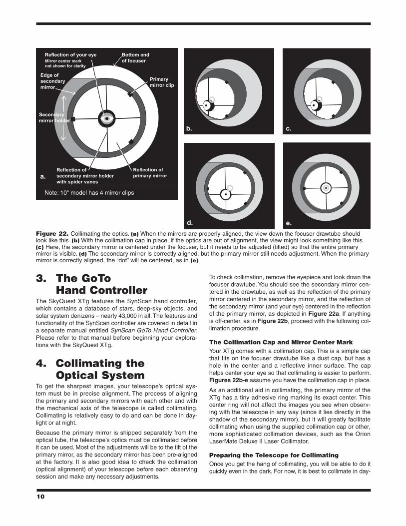
To check collimation, remove the eyepiece and look down the focuser drawtube. You should see the secondary mirror cen-tered in the drawtube, as well as the reflection of the primary mirror centered in the secondary mirror, and the reflection of the secondary mirror (and your eye) centered in the reflection of the primary mirror, as depicted in Figure 22a. If anything is off-center, as in Figure 22b, proceed with the following col-limation procedure.
the collimation cap and Mirror center MarkYour XTg comes with a collimation cap. This is a simple cap that fits on the focuser drawtube like a dust cap, but has a hole in the center and a reflective inner surface. The cap helps center your eye so that collimating is easier to perform. Figures 22b-e assume you have the collimation cap in place.
As an additional aid in collimating, the primary mirror of the XTg has a tiny adhesive ring marking its exact center. This center ring will not affect the images you see when observ-ing with the telescope in any way (since it lies directly in the shadow of the secondary mirror), but it will greatly facilitate collimating when using the supplied collimation cap or other, more sophisticated collimation devices, such as the Orion LaserMate Deluxe II Laser Collimator.
Preparing the telescope for collimatingOnce you get the hang of collimating, you will be able to do it quickly even in the dark. For now, it is best to collimate in day-
Figure 22. Collimating the optics. (a) When the mirrors are properly aligned, the view down the focuser drawtube should look like this. (b) With the collimation cap in place, if the optics are out of alignment, the view might look something like this. (c) Here, the secondary mirror is centered under the focuser, but it needs to be adjusted (tilted) so that the entire primary mirror is visible. (d) The secondary mirror is correctly aligned, but the primary mirror still needs adjustment. When the primary mirror is correctly aligned, the “dot” will be centered, as in (e).
a.
e.d.
c.b.
Note: 10" model has 4 mirror clips
11
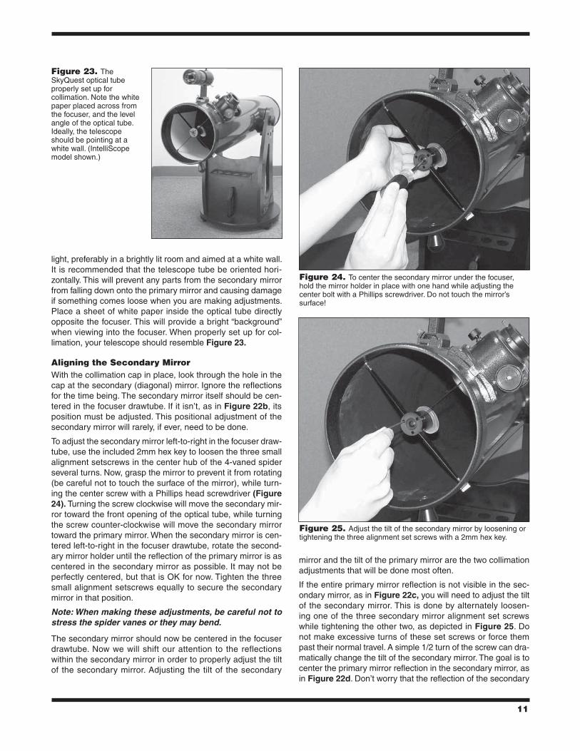
light, preferably in a brightly lit room and aimed at a white wall. It is recommended that the telescope tube be oriented hori-zontally. This will prevent any parts from the secondary mirror from falling down onto the primary mirror and causing damage if something comes loose when you are making adjustments. Place a sheet of white paper inside the optical tube directly opposite the focuser. This will provide a bright “background” when viewing into the focuser. When properly set up for col-limation, your telescope should resemble Figure 23.
aligning the secondary MirrorWith the collimation cap in place, look through the hole in the cap at the secondary (diagonal) mirror. Ignore the reflections for the time being. The secondary mirror itself should be cen-tered in the focuser drawtube. If it isn’t, as in Figure 22b, its position must be adjusted. This positional adjustment of the secondary mirror will rarely, if ever, need to be done.
To adjust the secondary mirror left-to-right in the focuser draw-tube, use the included 2mm hex key to loosen the three small alignment setscrews in the center hub of the 4-vaned spider several turns. Now, grasp the mirror to prevent it from rotating (be careful not to touch the surface of the mirror), while turn-ing the center screw with a Phillips head screwdriver (Figure 24). Turning the screw clockwise will move the secondary mir-ror toward the front opening of the optical tube, while turning the screw counter-clockwise will move the secondary mirror toward the primary mirror. When the secondary mirror is cen-tered left-to-right in the focuser drawtube, rotate the second-ary mirror holder until the reflection of the primary mirror is as centered in the secondary mirror as possible. It may not be perfectly centered, but that is OK for now. Tighten the three small alignment setscrews equally to secure the secondary mirror in that position.
Note: When making these adjustments, be careful not to stress the spider vanes or they may bend.
The secondary mirror should now be centered in the focuser drawtube. Now we will shift our attention to the reflections within the secondary mirror in order to properly adjust the tilt of the secondary mirror. Adjusting the tilt of the secondary
mirror and the tilt of the primary mirror are the two collimation adjustments that will be done most often.
If the entire primary mirror reflection is not visible in the sec-ondary mirror, as in Figure 22c, you will need to adjust the tilt of the secondary mirror. This is done by alternately loosen-ing one of the three secondary mirror alignment set screws while tightening the other two, as depicted in Figure 25. Do not make excessive turns of these set screws or force them past their normal travel. A simple 1/2 turn of the screw can dra-matically change the tilt of the secondary mirror. The goal is to center the primary mirror reflection in the secondary mirror, as in Figure 22d. Don’t worry that the reflection of the secondary
Figure 23. The SkyQuest optical tube properly set up for collimation. Note the white paper placed across from the focuser, and the level angle of the optical tube. Ideally, the telescope should be pointing at a white wall. (IntelliScope model shown.)
Figure 24. To center the secondary mirror under the focuser, hold the mirror holder in place with one hand while adjusting the center bolt with a Phillips screwdriver. Do not touch the mirror’s surface!
Figure 25. Adjust the tilt of the secondary mirror by loosening or tightening the three alignment set screws with a 2mm hex key.
12
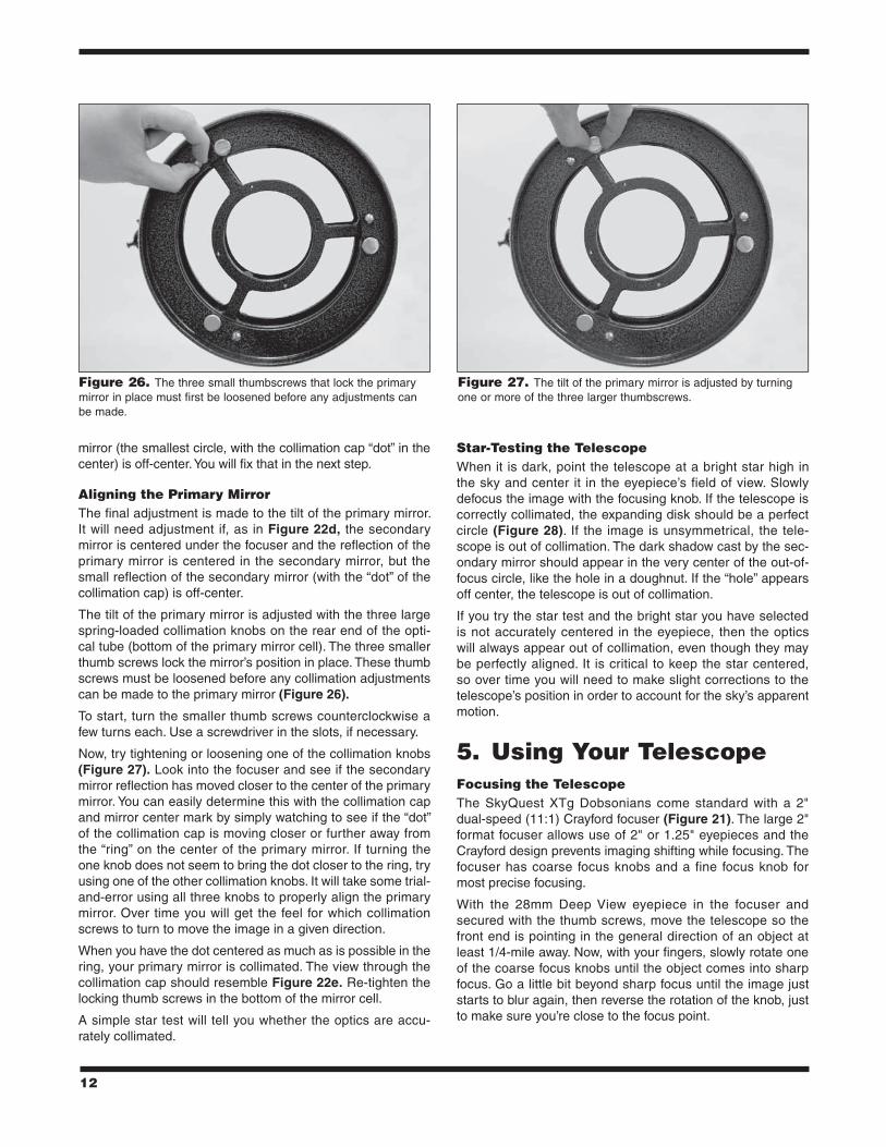
mirror (the smallest circle, with the collimation cap “dot” in the center) is off-center. You will fix that in the next step.
aligning the Primary MirrorThe final adjustment is made to the tilt of the primary mirror. It will need adjustment if, as in Figure 22d, the secondary mirror is centered under the focuser and the reflection of the primary mirror is centered in the secondary mirror, but the small reflection of the secondary mirror (with the “dot” of the collimation cap) is off-center.
The tilt of the primary mirror is adjusted with the three large spring-loaded collimation knobs on the rear end of the opti-cal tube (bottom of the primary mirror cell). The three smaller thumb screws lock the mirror’s position in place. These thumb screws must be loosened before any collimation adjustments can be made to the primary mirror (Figure 26).
To start, turn the smaller thumb screws counterclockwise a few turns each. Use a screwdriver in the slots, if necessary.
Now, try tightening or loosening one of the collimation knobs (Figure 27). Look into the focuser and see if the secondary mirror reflection has moved closer to the center of the primary mirror. You can easily determine this with the collimation cap and mirror center mark by simply watching to see if the “dot” of the collimation cap is moving closer or further away from the “ring” on the center of the primary mirror. If turning the one knob does not seem to bring the dot closer to the ring, try using one of the other collimation knobs. It will take some trial-and-error using all three knobs to properly align the primary mirror. Over time you will get the feel for which collimation screws to turn to move the image in a given direction.
When you have the dot centered as much as is possible in the ring, your primary mirror is collimated. The view through the collimation cap should resemble Figure 22e. Re-tighten the locking thumb screws in the bottom of the mirror cell.
A simple star test will tell you whether the optics are accu-rately collimated.
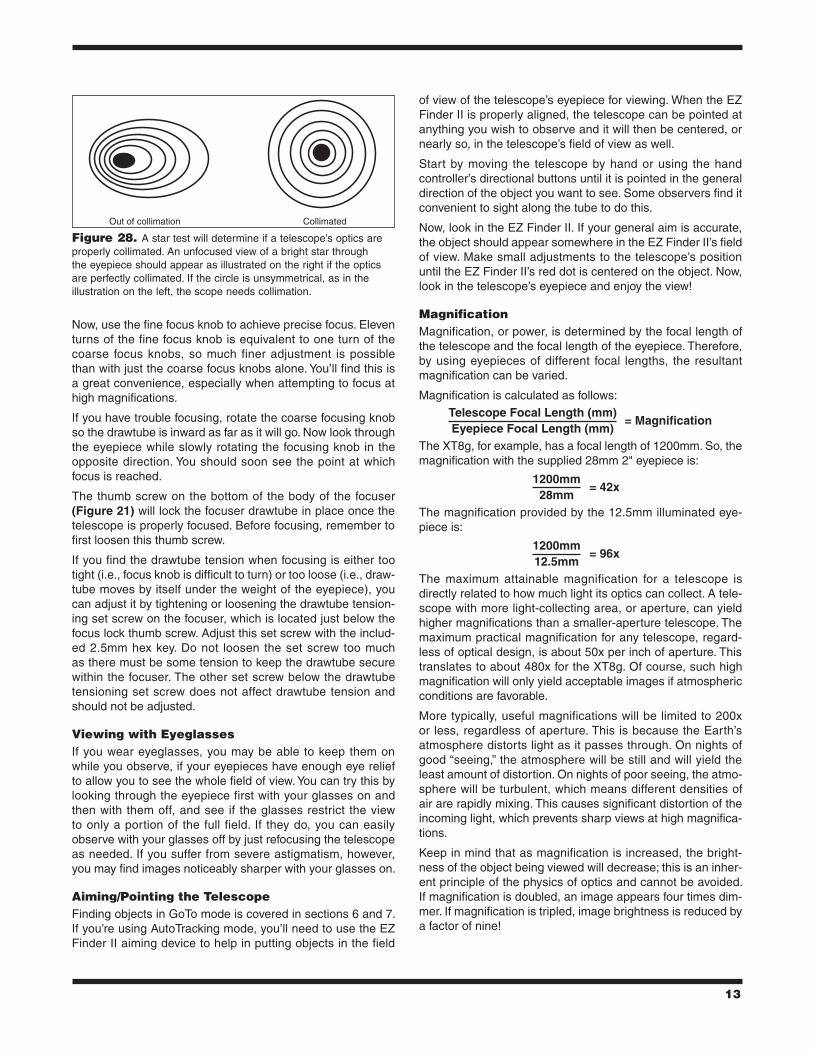
star-testing the telescopeWhen it is dark, point the telescope at a bright star high in the sky and center it in the eyepiece’s field of view. Slowly defocus the image with the focusing knob. If the telescope is correctly collimated, the expanding disk should be a perfect circle (Figure 28). If the image is unsymmetrical, the tele-scope is out of collimation. The dark shadow cast by the sec-ondary mirror should appear in the very center of the out-of-focus circle, like the hole in a doughnut. If the “hole” appears off center, the telescope is out of collimation.
If you try the star test and the bright star you have selected is not accurately centered in the eyepiece, then the optics will always appear out of collimation, even though they may be perfectly aligned. It is critical to keep the star centered, so over time you will need to make slight corrections to the telescope’s position in order to account for the sky’s apparent motion.
5. using Your telescopeFocusing the telescopeThe SkyQuest XTg Dobsonians come standard with a 2" dual-speed (11:1) Crayford focuser (Figure 21). The large 2" format focuser allows use of 2" or 1.25" eyepieces and the Crayford design prevents imaging shifting while focusing. The focuser has coarse focus knobs and a fine focus knob for most precise focusing.
With the 28mm Deep View eyepiece in the focuser and secured with the thumb screws, move the telescope so the front end is pointing in the general direction of an object at least 1/4-mile away. Now, with your fingers, slowly rotate one of the coarse focus knobs until the object comes into sharp focus. Go a little bit beyond sharp focus until the image just starts to blur again, then reverse the rotation of the knob, just to make sure you’re close to the focus point.
Figure 26. The three small thumbscrews that lock the primary mirror in place must first be loosened before any adjustments can be made.
Figure 27. The tilt of the primary mirror is adjusted by turning one or more of the three larger thumbscrews.
13
Now, use the fine focus knob to achieve precise focus. Eleven turns of the fine focus knob is equivalent to one turn of the coarse focus knobs, so much finer adjustment is possible than with just the coarse focus knobs alone. You’ll find this is a great convenience, especially when attempting to focus at high magnifications.
If you have trouble focusing, rotate the coarse focusing knob so the drawtube is inward as far as it will go. Now look through the eyepiece while slowly rotating the focusing knob in the opposite direction. You should soon see the point at which focus is reached.
The thumb screw on the bottom of the body of the focuser (Figure 21) will lock the focuser drawtube in place once the telescope is properly focused. Before focusing, remember to first loosen this thumb screw.
If you find the drawtube tension when focusing is either too tight (i.e., focus knob is difficult to turn) or too loose (i.e., draw-tube moves by itself under the weight of the eyepiece), you can adjust it by tightening or loosening the drawtube tension-ing set screw on the focuser, which is located just below the focus lock thumb screw. Adjust this set screw with the includ-ed 2.5mm hex key. Do not loosen the set screw too much as there must be some tension to keep the drawtube secure within the focuser. The other set screw below the drawtube tensioning set screw does not affect drawtube tension and should not be adjusted.
Viewing with EyeglassesIf you wear eyeglasses, you may be able to keep them on while you observe, if your eyepieces have enough eye relief to allow you to see the whole field of view. You can try this by looking through the eyepiece first with your glasses on and then with them off, and see if the glasses restrict the view to only a portion of the full field. If they do, you can easily observe with your glasses off by just refocusing the telescope as needed. If you suffer from severe astigmatism, however, you may find images noticeably sharper with your glasses on.
aiming/Pointing the telescopeFinding objects in GoTo mode is covered in sections 6 and 7. If you’re using AutoTracking mode, you’ll need to use the EZ Finder II aiming device to help in putting objects in the field
of view of the telescope’s eyepiece for viewing. When the EZ Finder II is properly aligned, the telescope can be pointed at anything you wish to observe and it will then be centered, or nearly so, in the telescope’s field of view as well.
Start by moving the telescope by hand or using the hand controller’s directional buttons until it is pointed in the general direction of the object you want to see. Some observers find it convenient to sight along the tube to do this.
Now, look in the EZ Finder II. If your general aim is accurate, the object should appear somewhere in the EZ Finder II’s field of view. Make small adjustments to the telescope’s position until the EZ Finder II’s red dot is centered on the object. Now, look in the telescope’s eyepiece and enjoy the view!
MagnificationMagnification, or power, is determined by the focal length of the telescope and the focal length of the eyepiece. Therefore, by using eyepieces of different focal lengths, the resultant magnification can be varied.
Magnification is calculated as follows:Telescope Focal Length (mm)
= MagnificationEyepiece Focal Length (mm)
The XT8g, for example, has a focal length of 1200mm. So, the magnification with the supplied 28mm 2" eyepiece is:
1200mm= 42x
28mmThe magnification provided by the 12.5mm illuminated eye-piece is:
1200mm= 96x
12.5mmThe maximum attainable magnification for a telescope is directly related to how much light its optics can collect. A tele-scope with more light-collecting area, or aperture, can yield higher magnifications than a smaller-aperture telescope. The maximum practical magnification for any telescope, regard-less of optical design, is about 50x per inch of aperture. This translates to about 480x for the XT8g. Of course, such high magnification will only yield acceptable images if atmospheric conditions are favorable.
More typically, useful magnifications will be limited to 200x or less, regardless of aperture. This is because the Earth’s atmosphere distorts light as it passes through. On nights of good “seeing,” the atmosphere will be still and will yield the least amount of distortion. On nights of poor seeing, the atmo-sphere will be turbulent, which means different densities of air are rapidly mixing. This causes significant distortion of the incoming light, which prevents sharp views at high magnifica-tions.
Keep in mind that as magnification is increased, the bright-ness of the object being viewed will decrease; this is an inher-ent principle of the physics of optics and cannot be avoided. If magnification is doubled, an image appears four times dim-mer. If magnification is tripled, image brightness is reduced by a factor of nine!
Figure 28. A star test will determine if a telescope’s optics are properly collimated. An unfocused view of a bright star through the eyepiece should appear as illustrated on the right if the optics are perfectly collimated. If the circle is unsymmetrical, as in the illustration on the left, the scope needs collimation.
Out of collimation Collimated

14
The SkyQuest XTg is designed to accept eyepieces with a barrel diameter of either 1.25" or 2". At low magnifications, 2" eyepieces can provide a wider field of view than standard 1.25" eyepieces. A wider field can be desirable for viewing extended deep sky objects that are too large to fit within a narrower field of view.
transporting the telescopeThe SkyQuest XTg Dobs have been designed to be easy to transport. The optical tube uncouples from the base by loos-ening a single hand knob, and the tube and base can be car-ried separately. The base has three carry handles for your convenience.
Before transporting the telescope, remove the EZ Finder II (with bracket) and any eyepieces from the optical tube. The eyepiece rack can also be removed from the base, if you wish. This will prevent these accessories from being damaged dur-ing transport. These items can be placed in optional acces-sory cases.
To remove the optical tube from the base, first orient the tube so it is horizontal. Then unthread the tube connecting knob (see Figure 19) until it disengages from the metal dovetail trunnion on the base. You needn’t unthread it completely from the telescope side bearing. Grasp the rear end ring of the tube with one hand and cradle underneath the front portion of tube with your other arm (see Figure 18). Then, using both hands, carefully lift the tube upward and off the base.
Note: If you choose to thread the knobs back into the alti-tude bearings after removing the optical tube from the base, be careful not to bend the knobs when transporting the telescope.
When putting the XTg into a vehicle, common sense prevails. It is especially important that the optical tube does not get knocked around; this can cause the optics to become mis-aligned, and could dent the tube.
We recommend transporting (and storing) the tube assembly in the optional padded case for proper protection.
6. astronomical observingThe SkyQuest XTg GoTo Dobsonian provides prodigious capability for observing the many wonders of the heavens, from the major planets to deep-space nebulas and galaxies. In this section we give you some astronomical observing tips and briefly summarize what you can expect to see.
selecting an observing siteSince most astronomical objects are faint, observing them from dark skies will give you the best views. While some objects, such as the planets and Moon, are bright enough to see clearly even from light-polluted city skies, for nebulas, galaxies, and most star clusters, the less ambient light there is to reduce contrast, the better.
When it isn’t possible or convenient to get out of town to a pitch-black observing location, try to set up in a spot that is removed from street and building lights and that has a clear view of a large portion of the sky. Avoid pointing the telescope above
buildings, if possible, since they radiate heat which degrades images. For observing faint deep sky objects, choose a moon-less night. Using the optional light shroud will be a necessity (see below). Also, use of a light-pollution filter, like the Orion SkyGlow Broadband filter, can mitigate the effects of back-ground sky brightness, enhancing the view of faint objects.
seeing and transparencyAtmospheric conditions play a huge part in quality of viewing. Light from stars and other celestial objects must travel through miles of Earth’s atmosphere to reach our eyes. The air in the atmosphere will refract and bend the light. Atmospheric tur-bulence will worsen the effects of refraction, which can cause the image you see in your telescope to be unstable. The steadiness of the atmosphere is called “seeing.”
In conditions of good “seeing,” star twinkling is minimal and objects appear steady in the eyepiece. Seeing is best over-head, worst at the horizon. Also, seeing generally gets bet-ter later in the evening as much of the heat absorbed by the Earth during the day has radiated off into space. In condi-tions of bad seeing, stars will twinkle and objects will appear unsteady and blurry in the telescope.
“Transparency” is the clarity of the atmosphere, which can be adversely affected by the presence of moisture, smoke, and dust. All tend to scatter light, which reduces an object’s brightness. Good transparency is desirable for astronomical observing, especially for viewing faint objects.
One good measure of transparency is by how many stars you can see with your unaided eyes. If you cannot see stars of magnitude 3.5 or dimmer then transparency is poor. Magnitude is a measure of how bright a star is. The brighter a star, the lower its magnitude. A good star to remember for this is Megrez (magnitude 3.4), which is the star in the Big Dipper that connects the handle to the “dipper.” If you cannot see Megrez, then you have fog, haze, clouds, smog, light pol-lution or other conditions that are hindering your viewing.
cooling the telescopeAll optical instruments need time to reach thermal equilibrium to achieve maximum stability of the lenses and mirrors, which is essential for peak performance. Images will be unstable if the optics are not in equilibrium with the outdoor temperature.
When moved from a warm indoor location outside to cooler air (or vice-versa), a telescope needs time to cool to the outdoor temperature. The bigger the instrument and the larger the tem-perature change, the more time will be needed. Allow at least 30 minutes or so to equilibrate. If the temperature difference between indoors and outdoors is more than 40°, it will likely take longer. In the winter, storing the telescope outdoors in a shed or garage greatly reduces the amount of time needed for the optics to stabilize. Also, after setting up outdoors, it is a good idea to keep the telescope covered until the Sun sets so the tube does not heat greatly above the temperature of the air.
let Your Eyes Dark-adaptDo not expect to go from a lighted house into the darkness of the outdoors at night and immediately see faint nebulas,

15
galaxies, and star clusters – or even very many stars, for that matter. Your eyes take about 30 minutes to reach per-haps 80% of their full dark-adapted sensitivity. Many observ-ers notice improvements after several hours of total darkness. As your eyes become dark-adapted, more stars will glimmer into view and you will be able to see fainter details in objects you view in your telescope. Exposing your eyes to very bright daylight for extended periods of time can adversely affect your night vision for days. So give yourself at least a little while to get used to the dark before you begin observing.
To see what you are doing in the darkness, use a red-filtered flashlight rather than a white light. Red light does not spoil your eyes’ dark adaptation like white light does. A flashlight with a red LED light is ideal. Dim light is preferable to bright light.
Be aware, too, that nearby porch and streetlights and auto-mobile headlights will spoil your night vision. Close your eyes when you hear an automobile approaching your observing site!
Eyepiece selectionBy using eyepieces of different focal lengths, it is possible to attain many different magnifications with your telescope. Different eyepieces can be used to achieve higher or lower powers. It is quite common for an observer to own five or more eyepieces to access a wide range of magnifications. This allows the observer to choose the best eyepiece to use depending on the object being viewed. At least to begin with, the two supplied eyepieces will suffice nicely.
Whatever you choose to view, always start by inserting your lowest-power (longest focal length) eyepiece to locate and center the object. Low magnification yields a wide field of view, which shows a larger area of sky in the eyepiece. This makes acquiring and centering an object much easier. If you try to find and center objects with high power (narrow field of view), it’s like trying to find a needle in a haystack! Once you’ve centered the object in the eyepiece, you can switch to higher magnification (shorter focal length eyepiece), if you wish. This is especially recommended for small and bright objects like planets and double stars. The Moon also takes higher magnifications well.
Deep sky objects, however, typically look better at medium or low magnifications. This is because many of them are quite faint, yet have some extent (apparent width). Deep sky objects will often disappear at higher magnifications, since greater magnification inherently yields dimmer images. This is not the case for all deep sky objects, however. Many galax-ies are quite small, yet are somewhat bright, so higher power may show more detail.
The best rule of thumb with eyepiece selection is to start with a low power, wide field, and then work your way up in magnifi-cation. If the object looks better, try an even higher magnifica-tion. If the object looks worse, then back off the magnification a little by using a lower power eyepiece.
astronomical objectsNow that you are all setup and ready to go, one critical deci-sion must be made: what to look at?
A. The Moon
With is rocky and cratered surface, the Moon is one of the most interesting and easy subjects to view with your tele-scope. The best time to view it is during its partial phases when shadows fall on the craters and canyon walls to give them definition. While the full moon may look like a tempting target, it is not optimal for viewing! The light is too bright and surface definition is low.
Even at partial phases the Moon is very bright. Use of an optional Moon filter helps to dim the glare. It simply threads onto the bottom of the eyepiece. You’ll find the Moon filter improves viewing comfort, and helps bring out the subtle fea-tures of the lunar surface.
B. The Sun
You can change your nighttime telescope into a daytime Sun viewer by installing an optional solar filter over the front open-ing of the telescope. The primary attraction is sunspots, which change shape, appearance, and location daily. Sunspots are directly related to magnetic activity in the Sun. Many observ-ers like to make drawings of sunspots to monitor how the Sun is changing from day to day.
Important Note: Do not look at the Sun with any optical instrument without a professionally made solar filter, or permanent eye damage could result. Also, be sure to cover the finder scope, or better yet, remove it altogether.
C. The Planets
The planets don’t stay put like the stars, so to find them you should refer to Sky Calendar at our website OrionTelescopes.com, or use the IntelliScope Object Locator. Venus, Mars, Jupiter, and Saturn are the brightest objects in the sky after the Sun and the Moon. Your XTg is capable of showing you these planets in some detail. Other planets may be visible but will likely appear star-like. Because planets are quite small in apparent size, optional higher power eyepieces are recom-mended and often needed for detailed observations. Not all the planets are generally visible at any one time.
Jupiter: The largest planet, Jupiter, is a great subject for observation. You can see the disk of the giant planet and watch the ever-changing positions of its four largest moons: Io, Callisto, Europa, and Ganymede. Higher power eyepieces should bring out the cloud bands on the planet’s disk.
Saturn: The ringed planet is a breathtaking sight. The tilt angle of the rings varies over a period of many years; some-times they are seen edge-on, while at other times they are broadside and look like giant “ears” on each side of Saturn’s disk. A steady atmosphere (good seeing) is necessary for a good view. Look closely and you may see the Cassini division, a thin, dark gap in the rings. You should also see one or more of Saturn’s moons, which look like faint stars. The brightest is the moon Titan.
Venus: At its brightest, Venus is the most luminous object in the sky, excluding the Sun and the Moon. It is so bright that

16
sometimes it is visible to the naked eye during full daylight! Ironically, Venus appears as a thin crescent, not a full disk, when at its peak brightness. Because it is so close to the Sun, it never wanders too far from the morning or evening horizon. No surface markings can be seen on Venus, which is always shrouded in dense clouds.
Mars: The Red Planet makes a close approach to Earth every two years. Observing Mars is most favorable at these times. You should see a salmon-colored disk with some distinct dark patches, and you may be able to spot a whitish polar ice cap. To see surface detail on Mars, you will need a high power eyepiece and very steady air!
D. The Stars
Stars will appear as tiny points of light. Even powerful tele-scopes cannot magnify stars to appear as anything more than pinpoints. You can, however, enjoy the different colors of the stars and locate many pretty double and multiple stars. The famous “Double-Double” in the constellation Lyra and the gor-geous two-color double star Albireo in Cygnus are favorites. Defocusing a star slightly can help bring out its color.
E. Deep Sky Objects
Under dark skies, you can observe a wealth of fascinating deep sky objects; that is, objects that reside outside of our solar system. These include gaseous nebulas, open and glob-ular star clusters, and a variety of different types of galaxies.
The large aperture of the XTg is particularly well suited to gathering light, which is critical for observing these usually faint celestial entities. For deep sky observing it is important that you find an observing site well away from light pollution. Take plenty of time to let your eyes adjust to the darkness. As you become more experienced and your observing skills get sharper, you will be able to ferret out more and more subtle details and structure from these fascinating objects.
Beginners are often surprised to discover that the deep sky objects they see through the eyepiece of a telescope are mostly grayish, not colorful like those you see in long-expo-sure astro-images. The reason is that our eyes are not sensi-tive to color in faint light. Still, there is something very special about seeing an astronomical object in real time with your own eyes – “live,” if not in living color.
note about astro-imagingThe SkyQuest XTg GoTo Dobsonian is designed for visual, not imaging, use. With that in mind, however, it is possible to do some simple lunar and planetary astro-imaging with the XTg. With the use of afocal imaging techniques (where the camera is simply put right up to the eyepiece to take a picture) and digital cameras, it is possible to capture images of bright objects. Certain imaging accessories, such as the Orion SteadyPix, can help in obtaining images by the afocal method.
Deep-sky photography is not recommended with the SkyQyest XTg Dobs. For the longer exposures required for deep-sky photography, an equatorial mount is needed, or an altazimuth mount equipped with a field rotator.
7. specificationsskyQuest Xt8gPrimary mirror: 203mm diameter, parabolic, center-marked
Focal length: 1200mm
Focal ratio: f/5.9
Focuser: Dual-speed Crayford (11:1), accepts 2" and 1.25" eyepieces with included adapter
Optical tube material: Rolled steel
Azimuth bearing: Thrust needle bearing
Altitude bearing: Ball bearing
Eyepieces: 28mm DeepView, 2" barrel, 12.5mm Illuminated Plössl, 1.25" barrel
Eyepiece magnifications: 42x and 96x
Finder scope: EZ Finder II Reflex Sight
Eyepiece rack: Holds three 1.25" eyepieces and one 2" eyepiece
Mirror coatings: Enhanced aluminum with SiO2 overcoat
Minor axis of secondary mirror: 47.0mm
Optical tube weight: 19.7 lbs.
Base weight: 38.5 lbs.
Tube length: 46.5"
Tube outer diameter: 9.25"
Motor drives: Dual-axis GoTo computerized, internally housed
Operation: Northern or Southern hemisphere
Power requirement: 12V DC 2.1 Amp (tip positive)
Motor type: DC servo with optical encoders for altitude and azimuth axes
Slew speeds: Rate 0 = 1.0X Rate 1 = 2X Rate 2 = 16X Rate 3 = 32X Rate 4 = 50X Rate 5 = 200X Rate 6 = 400X Rate 7 = 600X Rate 8 = 800X Rate 9 = 1000X
Tracking rates: Sidereal (default), Lunar, Solar.
Alignment method: Brightest Star, Two-Star
Database: Over 42,900 objects including: Complete Messier & Caldwell catalogs, 7840 NGC objects, 5386 IC objects, 29523 SAO stars, 8 planets, moon, 212 named stars, 55 well-known double stars, 20 well-known variable stars, 25 user-defined objects.

17
skyQuest Xt10gPrimary mirror: 254mm diameter, parabolic, center-marked
Focal length: 1200mm
Focal ratio: f/4.7
Focuser: Dual-speed Crayford (11:1), accepts 2" and 1.25" eyepieces with included adapter
Optical tube material: Rolled steel
Azimuth bearing: Thrust needle bearing
Altitude bearing: Ball bearing
Eyepieces: 28mm DeepView, 2" barrel, 12.5mm Illuminated Plössl, 1.25" barrel
Eyepiece magnifications: 42x and 96x
Finder scope: EZ Finder II Reflex Sight
Eyepiece rack: Holds three 1.25" eyepieces and one 2" eyepiece
Mirror coatings: Enhanced aluminum with SiO2 overcoat
Minor axis of secondary mirror: 63.0mm
Optical tube weight: 29.4 lbs.
Base weight: 38.5 lbs.
Tube length: 47.25"
Tube outer diameter: 12.0"
Motor drives: Dual-axis GoTo computerized, internally housed
Operation: Northern or Southern hemisphere
Power requirement: 12V DC 2.1 Amp (tip positive)
Motor type: DC servo with optical encoders for altitude and azimuth axes
Slew speeds: Rate 0 = 1.0X Rate 1 = 2X Rate 2 = 16X Rate 3 = 32X Rate 4 = 50X Rate 5 = 200X Rate 6 = 400X Rate 7 = 600X Rate 8 = 800X Rate 9 = 1000X
Tracking rates: Sidereal (default), Lunar, Solar.
Alignment method: Brightest Star, Two-Star
Database: Over 42,900 objects including: Complete Messier & Caldwell catalogs, 7840 NGC objects, 5386 IC objects, 29523 SAO stars, 8 planets, moon, 212 named stars, 55 well-known double stars, 20 well-known variable stars, 25 user-defined objects.
skyQuest Xt12gPrimary mirror: 305mm diameter, parabolic, center-marked
Focal length: 1500mm
Focal ratio: f/4.9
Focuser: Dual-speed Crayford (11:1), accepts 2" and 1.25" eyepieces
Optical tube material: Rolled steel
Azimuth bearing: Thrust needle bearing
Altitude bearing: Ball bearing
Eyepieces: 28mm DeepView, 2" barrel, 12.5mm Illuminated Plössl, 1.25" barrel
Eyepiece magnifications: 53x and 120x
Finder scope: EZ Finder II Reflex Sight
Eyepiece rack: Holds three 1.25" eyepieces and one 2" eyepiece
Mirror coatings: Enhanced aluminum with SiO2 overcoat
Minor axis of secondary mirror: 70mm
Optical tube weight: 48.9 lbs.
Base weight: 52.9 lbs.
Tube length: 58"
Tube outer diameter: 14"
Motor drives: Dual-axis GoTo computerized, internally housed
Operation: Northern or Southern hemisphere
Power requirement: 12V DC 2.1 Amp (tip positive)
Motor type: DC servo with optical encoders for altitude and azimuth axes
Slew speeds: Rate 0 = 1.0X Rate 1 = 2X Rate 2 = 16X Rate 3 = 32X Rate 4 = 50X Rate 5 = 200X Rate 6 = 400X Rate 7 = 600X Rate 8 = 800X Rate 9 = 1000X
Tracking rates: Sidereal (default), Lunar, Solar.
Alignment method: Brightest Star, Two-Star
Database: Over 42,900 objects including: Complete Messier & Caldwell catalogs, 7840 NGC objects, 5386 IC objects, 29523 SAO stars, 8 planets, moon, 212 named stars, 55 well-known double stars, 20 well-known variable stars, 25 user-defined objects.

one-Year limited WarrantyThis Orion product is warranted against defects in materials or workmanship for a period of one year from the date of purchase. This warranty is for the benefit of the original retail purchaser only. During this war-ranty period Orion Telescopes & Binoculars will repair or replace, at Orion’s option, any warranted instru-ment that proves to be defective, provided it is returned postage paid. Proof of purchase (such as a copy of the original receipt) is required. This warranty is only valid in the country of purchase.
This warranty does not apply if, in Orion’s judgment, the instrument has been abused, mishandled, or modified, nor does it apply to normal wear and tear. This warranty gives you specific legal rights. It is not intended to remove or restrict your other legal rights under applicable local consumer law; your state or national statutory consumer rights governing the sale of consumer goods remain fully applicable.
For further warranty information, please visit www.OrionTelescopes.com/warranty.
Orion Telescopes & Binoculars
Corporate Offices: 89 Hangar Way, Watsonville CA 95076 - USA
Customer Support: www.OrionTelescopes.com/contactus
© Copyright 2010-2013 Orion Telescopes & Binoculars