original signed by: michael c. artist
TRANSCRIPT

Distribution: Electronic Initiated By: AJR-0 Vice President, System Operations Services
This order prescribes air traffic control procedures and phraseology for use by personnel providing air traffic control services. Controllers are required to be familiar with the provisions of this order that pertain to their operational responsibilities and to exercise judgment if they encounter situations not covered by it.
Original Signed By: Michael C. Artist
Michael C. Artist Vice President, System Operations Services Air Traffic Organization
Date: September 1, 2017
Effective Date: 10/12/2017
Air Traffic Organization Policy
SUBJ: Flight Services
ORDER JO 7110.10Z

DIRECTIVE NO.RECORD OF CHANGES JO 7110.10ZCHANGE
TOBASIC
SUPPLEMENTSOPTIONAL
CHANGETO
BASICSUPPLEMENTS
OPTIONAL
FAA Form 1320−5 (6−80) USE PREVIOUS EDITION

JO 7110.10Z10/12/17
Explanation of Changes E of C−1
Flight Services Explanation of Changes
BasicDirect questions through appropriate facility/service center office staff
to the Office of Primary Interest (OPI)
i. 3−2−1. CONDUCT OF STANDARDBRIEFINGThis change adds a note regarding special awarenessinformation for flights in and around Special FlightRules Areas and areas that require Special Air TrafficRules (SATR).
j. Entire Publication
Additional editorial/format changes were madewhere necessary. Revision bars were not usedbecause of the insignificant nature of these changes.


Distribution: Electronic Initiated By: AJR-0 Vice President, System Operations Services
CHANGE U.S. DEPARTMENT OF TRANSPORTATIONFEDERAL AVIATION ADMINISTRATION
JO 7110.10Z CHG 1
Air Traffic Organization Policy Effective Date: March 29, 2018
SUBJ: Flight Services
1. Purpose of This Change. This change transmits revised pages to Federal AviationAdministration Order JO 7110.10Z, Flight Services, and the Briefing Guide.
2. Audience. This change applies to select offices in Washington headquarters, service areaoffices, the William J. Hughes Technical Center, the Mike Monroney Aeronautical Center, andto all air traffic field facilities, international aviation field offices, and the interested aviationpublic.
3. Where Can I Find This Change? This change is available on the FAA Web site athttp://faa.gov/air_traffic/publications and http://employees.faa.gov/tools_resources/orders_ notices/.
4. Explanation of Policy Change. See the Explanation of Changes attachment which haseditorial corrections and changes submitted through normal procedures. The Briefing Guide listsonly new or modified material, along with background.
5. Distribution. This change is distributed to select offices in Washington headquarters,service area offices, the William J. Hughes Technical Center, the Mike Monroney AeronauticalCenter, and to all air traffic field facilities, international aviation field offices, and the interestedaviation public.
6. Disposition of Transmittal. Retain this transmittal until superseded by a new basic order.
7. Page Control Chart. See the page control chart attachment.
Original Signed By: Michael C. Artist
Michael C. Artist Vice President, System Operations Services Air Traffic Organization
Date: March 5, 2018


JO 7110.10Z CHG 13/29/18
Explanation of Changes E of C−1
Flight Services Explanation of Changes
Change 1Direct questions through appropriate facility/service center office staff
to the Office of Primary Interest (OPI)
f. 2−3−2. AREA/ROUTE BRIEFINGPROCEDURES
3−2−1. CONDUCT OF STANDARDBRIEFING
9−5−1. GENERAL9−5−2. AREA FORECAST (FA)
SCHEDULE9−5−3. DISTRIBUTION
This change retires the textual Area Forecast for theCONUS only and adds information about the newStatic Graphical Forecast Images (Aviation SurfaceForecast and Aviation Cloud Forecast).
g. 10−1−9. SIMULTANEOUS APPROACHAND RUNWAY EDGE LIGHT OPERATIONRunway and approach lighting must be operated inaccordance with the criteria contained in Paragraphs10−1−4, Approach Lights, and 10−1−7, RunwayEdge Lights. Runway edge lights are not required ona runway to which an approach is being made whenthe landing will be made on another runway.Therefore, this paragraph is being deleted.
h. Entire PublicationAdditional editorial/format changes were madewhere necessary. Revision bars were not usedbecause of the insignificant nature of these changes.


Distribution: Electronic Initiated By: AJR-0 Vice President, System Operations Services
CHANGE U.S. DEPARTMENT OF TRANSPORTATION
FEDERAL AVIATION ADMINISTRATION
JO 7110.10Z CHG 2
Air Traffic Organization Policy Effective Date:
September 13, 2018
SUBJ: Flight Services
1. Purpose of This Change. This change transmits revised pages to Federal Aviation
Administration Order JO 7110.10Z, Flight Services, and the Briefing Guide.
2. Audience. This change applies to select offices in Washington headquarters, service area
offices, the William J. Hughes Technical Center, the Mike Monroney Aeronautical Center, and
to all air traffic field facilities, international aviation field offices, and the interested aviation
public.
3. Where Can I Find This Change? This change is available on the FAA Web site at
http://faa.gov/air_traffic/publications and http://employees.faa.gov/tools_resources/orders_ notices/.
4. Explanation of Policy Change. See the Explanation of Changes attachment which has
editorial corrections and changes submitted through normal procedures. The Briefing Guide lists
only new or modified material, along with background.
5. Distribution. This change is distributed to select offices in Washington headquarters,
service area offices, the William J. Hughes Technical Center, the Mike Monroney Aeronautical
Center, and to all air traffic field facilities, international aviation field offices, and the interested
aviation public.
6. Disposition of Transmittal. Retain this transmittal until superseded by a new basic order.
7. Page Control Chart. See the page control chart attachment.
Original Signed By: Michael C. Artist
Michael C. Artist
Vice President, System Operations Services
Air Traffic Organization
Date: August 8, 2018


JO 7110.10Z CHG 29/13/18
Explanation of Changes E of C−1
Flight Services Explanation of Changes
Change 2Direct questions through appropriate facility/service center office staff
to the Office of Primary Interest (OPI)
a. 1−1−6. SUBMISSION CUTOFF ANDEFFECTIVE DATES
1−1−8. RECOMMENDATIONS FORPROCEDURAL CHANGES
This change adds language to clarify the submissionguidelines for changes to this Order. It changes“Cutoff date for Submission” to “Cutoff date forCompletion” to clarify that even after changes aresubmitted to the correspondence mailbox, severalmonths of coordination are often still required beforethey are completed and submitted internally forpublication. It also adds a Note referencing FAAOrder JO 7000.5, Procedures for SubmittingChanges to Air Traffic Control Publications.
b. 3−1−4. WEATHER DISPLAY PRODUCTS4−1−1. INFLIGHT SERVICES
This change includes weather display informationthat should have been relocated when En RouteAdvisory Service was terminated in FAA Order JO7110.10Y, Change 1. This change cancels andincorporates N JO 7110.751.
c. 3−1−8. LOGGING PILOT BRIEFINGS4−2−3. IFR/VFR/DVFR FLIGHT PLAN
RECORDING6−1−6. IFR/VFR/DVFR FLIGHT PLAN
RECORDING
This change supports the standardized use of FAAForm 7233−4, International Flight Plan.
d. 9−2−14. PIREP FORMAT12−1−8. WEATHER PHRASEOLOGY
This change adds clarity to the meteorologicalphenomena that is reported by the weather observerdistinguishing between small hail and snow pellets.
e. Entire Publication
Additional editorial/format changes were madewhere necessary. Revision bars were not usedbecause of the insignificant nature of these changes.


Distribution: Electronic Initiated By: AJR-0 Vice President, System Operations Services
CHANGE U.S. DEPARTMENT OF TRANSPORTATION
FEDERAL AVIATION ADMINISTRATION
JO 7110.10Z CHG 3
Air Traffic Organization Policy Effective Date:
February 28, 2019
SUBJ: Flight Services
1. Purpose of This Change. This change transmits revised pages to Federal Aviation
Administration Order JO 7110.10Z, Flight Services, and the Briefing Guide.
2. Audience. This change applies to select offices in Washington headquarters, service area
offices, the William J. Hughes Technical Center, the Mike Monroney Aeronautical Center, and
to all air traffic field facilities, international aviation field offices, and the interested aviation
public.
3. Where Can I Find This Change? This change is available on the FAA Web site at
http://faa.gov/air_traffic/publications and http://employees.faa.gov/tools_resources/orders_ notices/.
4. Explanation of Policy Change. See the Explanation of Changes attachment which has
editorial corrections and changes submitted through normal procedures. The Briefing Guide lists
only new or modified material, along with background.
5. Distribution. This change is distributed to select offices in Washington headquarters,
service area offices, the William J. Hughes Technical Center, the Mike Monroney Aeronautical
Center, and to all air traffic field facilities, international aviation field offices, and the interested
aviation public.
6. Disposition of Transmittal. Retain this transmittal until superseded by a new basic order.
7. Page Control Chart. See the page control chart attachment.
Original Signed By: Michael C. Artist
Michael C. Artist
Vice President, System Operations Services
Air Traffic Organization
Date: February 6, 2019


JO 7110.10Z CHG 32/28/19
Explanation of Changes E of C−1
Flight Services Explanation of Changes
Change 3
Direct questions through appropriate facility/service center office staffto the Office of Primary Interest (OPI)
a. 2−1−1. TYPES OF BROADCASTS2−1−3. REDUCING RECORDED
WEATHER INFORMATION SERVICES2−3−1. GENERAL
This change documents that Telephone InformationBriefing Services (TIBS) will only be provided byAlaska Flight Service Stations. This change cancelsand incorporates N JO 7110.760, effective September13, 2018.
b. 3−2−1. CONDUCT OF STANDARDBRIEFING
This change advises NAS users of updates to FAApublications, reflecting a more accurate means ofobtaining IFR route and procedures FDC NOTAMinformation.
c. 4−3−7. ATC CLEARANCES,ADVISORIES, OR REQUESTS
This change provides instruction to the Flight DataCommunications Specialists at the ARTCCs on howto properly obtain and relay clearance requests.
d. 7−1−1. GENERAL7−2−1. FLIGHT PLAN/CUSTOMS
REQUIREMENTS7−2−2. INBOUND AIRCRAFT: CUSTOMS
REQUIREMENTS7−2−3. INBOUND AIRCRAFT: ADIZ
REQUIREMENTS7−4−1. GENERAL7−4−2. INBOUNDS FROM CANADA7−4−3. OUTBOUNDS TO CANADA7−4−4. OUTBOUNDS TO CANADA
DEPARTING FROM OUTSIDE FLIGHT PLANAREA
7−5−1. GENERAL7−5−2. INBOUNDS FROM MEXICO7−5−3. OUTBOUNDS TO MEXICO
As a result of the changes cited above in the U.S.customs notifications procedures, Chapter 7 wasmodified to remove all references to ADCUS inremarks, provide guidance and a link to the CBPwebsite on the APIS requirements for pilots tocoordinate directly with CBP, and to update thesections on Canadian and Mexican trans−borderflights.
e. 8−2−1. COMMUNICATIONS SEARCH8−2−2. QALQ8−3−1. INREQ8−4−1. ALNOT
This change removes all references to Direct UsersAccess Terminal System (DUATS) II contract,including references to vendors CSRA and LockheedMartin. This system has been terminated and is nolonger available to the flying community.
f. 9−2−3. RESPONSIBILITY9−2−5. SOLICITING PIREPS9−2−14. PIREP FORMATTING
This change incorporates the ATO’s Top 5 PIREPCAP recommendations, and FAA Order JO 7110.10contains consistent guidance regarding the solicita-tion and dissemination of PIREPs. Specifically, itincludes requirements for the solicitation of moredetailed information regarding cloud ceilings andbraking action reports.
g. 9−5−2. AVIATION SURFACEFORECAST/ AVIATION CLOUDFORECAST/ AREA FORECAST (FA)SCHEDULE
9−5−3. AVIATION SURFACE FORECASTAND AVIATION CLOUD FORECASTISSUANCE TIMES
This change removes incorrect headers from Section9−5−2 and TBL 9−5−2 and also removes the incorrectdistribution information in Section 9−5−3. Thischange cancels and incorporates N JO 7110.759,effective September 5, 2018.

JO 7110.10Z CHG 3 2/28/19
E of C−2 Explanation of Changes
h. APPENDIX A. INSTRUCTIONS FORTHE COMPLETION OF THE FLIGHT PLANFORM
This change removes the “Reserved for RCP”description for the P−Code and includes the P−Codeequipment definitions. Additionally, this changeadds guidance for the filing of Required SurveillancePerformance (RSP) information in Item 18 of theflight plan. This is in conjunction with changes to theUnited States (U.S.), Aeronautical Information Man-
ual Table 5−1−4 and the U.S. Aeronautical Informa-tion Publication ENR 1.10 12.5.
i. EDITORIALS
Editorial changes include an update to DEN informa-tion in paragraph 5−2−13 as well as a referencecorrection in paragraph 4−1−1.
j. Entire Publication
Additional editorial/format changes were madewhere necessary. Revision bars were not usedbecause of the insignificant nature of these changes.

JO 7110.10Z CHG 32/28/19
iTable of Contents
Table of Contents
Chapter 1. General
Section 1. Introduction
Paragraph Page1−1−1. PURPOSE OF THIS ORDER 1−1−1. . . . . . . . . . . . . . . . . . . . . . . . . . . . . . . . . . . . . . . . . . . .1−1−2. AUDIENCE 1−1−1. . . . . . . . . . . . . . . . . . . . . . . . . . . . . . . . . . . . . . . . . . . . . . . . . . . . . . . . . .1−1−3. WHERE TO FIND THIS ORDER 1−1−1. . . . . . . . . . . . . . . . . . . . . . . . . . . . . . . . . . . . . . . .1−1−4. WHAT THIS ORDER CANCELS 1−1−1. . . . . . . . . . . . . . . . . . . . . . . . . . . . . . . . . . . . . . . .1−1−5. EXPLANATION OF CHANGES 1−1−1. . . . . . . . . . . . . . . . . . . . . . . . . . . . . . . . . . . . . . . . .1−1−6. EFFECTIVE DATES AND SUBMISSIONS FOR CHANGES 1−1−1. . . . . . . . . . . . . . . . . .1−1−7. DELIVERY DATES 1−1−1. . . . . . . . . . . . . . . . . . . . . . . . . . . . . . . . . . . . . . . . . . . . . . . . . . .1−1−8. RECOMMENDATIONS FOR PROCEDURAL CHANGES 1−1−1. . . . . . . . . . . . . . . . . . . .1−1−9. SUBSCRIPTION INFORMATION 1−1−2. . . . . . . . . . . . . . . . . . . . . . . . . . . . . . . . . . . . . . . .1−1−10. DISTRIBUTION 1−1−2. . . . . . . . . . . . . . . . . . . . . . . . . . . . . . . . . . . . . . . . . . . . . . . . . . . . .
Section 2. Terms of Reference
1−2−1. WORD MEANINGS 1−2−1. . . . . . . . . . . . . . . . . . . . . . . . . . . . . . . . . . . . . . . . . . . . . . . . . . .1−2−2. NOTES 1−2−1. . . . . . . . . . . . . . . . . . . . . . . . . . . . . . . . . . . . . . . . . . . . . . . . . . . . . . . . . . . . .1−2−3. EXAMPLES 1−2−1. . . . . . . . . . . . . . . . . . . . . . . . . . . . . . . . . . . . . . . . . . . . . . . . . . . . . . . . .1−2−4. PHRASEOLOGY 1−2−1. . . . . . . . . . . . . . . . . . . . . . . . . . . . . . . . . . . . . . . . . . . . . . . . . . . . .1−2−5. ABBREVIATIONS 1−2−1. . . . . . . . . . . . . . . . . . . . . . . . . . . . . . . . . . . . . . . . . . . . . . . . . . . .1−2−6. JO 7110.10 CHANGES 1−2−1. . . . . . . . . . . . . . . . . . . . . . . . . . . . . . . . . . . . . . . . . . . . . . . . .1−2−7. SYSTEM INSTRUCTIONS 1−2−2. . . . . . . . . . . . . . . . . . . . . . . . . . . . . . . . . . . . . . . . . . . . .
Section 3. Responsibility
1−3−1. PROCEDURAL APPLICATIONS 1−3−1. . . . . . . . . . . . . . . . . . . . . . . . . . . . . . . . . . . . . . . .1−3−2. DUTY PRIORITY 1−3−1. . . . . . . . . . . . . . . . . . . . . . . . . . . . . . . . . . . . . . . . . . . . . . . . . . . . .1−3−3. DUTY FAMILIARIZATION AND TRANSFER OF POSITION RESPONSIBILITY 1−3−1
Chapter 2. Broadcast Procedures
Section 1. General
2−1−1. TYPES OF BROADCASTS 2−1−1. . . . . . . . . . . . . . . . . . . . . . . . . . . . . . . . . . . . . . . . . . . . .2−1−2. SPEECH RATE AND PHRASEOLOGY 2−1−1. . . . . . . . . . . . . . . . . . . . . . . . . . . . . . . . . . .2−1−3. REDUCING RECORDED WEATHER INFORMATION SERVICES 2−1−1. . . . . . . . . . . .2−1−4. CURRENT DATA 2−1−1. . . . . . . . . . . . . . . . . . . . . . . . . . . . . . . . . . . . . . . . . . . . . . . . . . . . .2−1−5. AUTOMATED BROADCAST 2−1−1. . . . . . . . . . . . . . . . . . . . . . . . . . . . . . . . . . . . . . . . . . .
Section 2. Transcribed Weather Broadcasts (TWEB) (Alaska Only)
2−2−1. GENERAL 2−2−1. . . . . . . . . . . . . . . . . . . . . . . . . . . . . . . . . . . . . . . . . . . . . . . . . . . . . . . . . . .2−2−2. CONTENT 2−2−1. . . . . . . . . . . . . . . . . . . . . . . . . . . . . . . . . . . . . . . . . . . . . . . . . . . . . . . . . . .2−2−3. TESTING TWEB EQUIPMENT 2−2−2. . . . . . . . . . . . . . . . . . . . . . . . . . . . . . . . . . . . . . . . .2−2−4. SERVICE MAY BE SUSPENDED 2−2−2. . . . . . . . . . . . . . . . . . . . . . . . . . . . . . . . . . . . . . . .2−2−5. MONITORING 2−2−2. . . . . . . . . . . . . . . . . . . . . . . . . . . . . . . . . . . . . . . . . . . . . . . . . . . . . . .
Section 3. Telephone Information Briefing Service (TIBS)
2−3−1. GENERAL 2−3−1. . . . . . . . . . . . . . . . . . . . . . . . . . . . . . . . . . . . . . . . . . . . . . . . . . . . . . . . . . .

JO 7110.10Z CHG 3 2/28/19
ii Table of Contents
Paragraph Page2−3−2. AREA/ROUTE BRIEFING PROCEDURES 2−3−1. . . . . . . . . . . . . . . . . . . . . . . . . . . . . . . .2−3−3. MONITORING 2−3−2. . . . . . . . . . . . . . . . . . . . . . . . . . . . . . . . . . . . . . . . . . . . . . . . . . . . . . .
Section 4. Hazardous Inflight Weather Advisory Service (HIWAS)
2−4−1. GENERAL 2−4−1. . . . . . . . . . . . . . . . . . . . . . . . . . . . . . . . . . . . . . . . . . . . . . . . . . . . . . . . . . .2−4−2. PRIORITY 2−4−1. . . . . . . . . . . . . . . . . . . . . . . . . . . . . . . . . . . . . . . . . . . . . . . . . . . . . . . . . . .2−4−3. CONTENT 2−4−1. . . . . . . . . . . . . . . . . . . . . . . . . . . . . . . . . . . . . . . . . . . . . . . . . . . . . . . . . . .2−4−4. BROADCAST PROCEDURES 2−4−1. . . . . . . . . . . . . . . . . . . . . . . . . . . . . . . . . . . . . . . . . .2−4−5. SUSPENSION 2−4−2. . . . . . . . . . . . . . . . . . . . . . . . . . . . . . . . . . . . . . . . . . . . . . . . . . . . . . . .
Section 5. Automatic Flight Information Service (AFIS) (Alaska Only)
2−5−1. AUTOMATIC FLIGHT INFORMATION SERVICE (AFIS) 2−5−1. . . . . . . . . . . . . . . . . . . .
Chapter 3. Pilot Briefing
Section 1. General
3−1−1. DEFINITION 3−1−1. . . . . . . . . . . . . . . . . . . . . . . . . . . . . . . . . . . . . . . . . . . . . . . . . . . . . . . . .3−1−2. PRE-DUTY REQUIREMENTS 3−1−1. . . . . . . . . . . . . . . . . . . . . . . . . . . . . . . . . . . . . . . . . .3−1−3. PREFLIGHT BRIEFING DISPLAY 3−1−1. . . . . . . . . . . . . . . . . . . . . . . . . . . . . . . . . . . . . . .3−1−4. WEATHER DISPLAY PRODUCTS 3−1−1. . . . . . . . . . . . . . . . . . . . . . . . . . . . . . . . . . . . . . .3−1−5. FORECASTS, WARNINGS, AND ADVISORIES 3−1−2. . . . . . . . . . . . . . . . . . . . . . . . . . .3−1−6. UNAVAILABILITY OF DATA 3−1−3. . . . . . . . . . . . . . . . . . . . . . . . . . . . . . . . . . . . . . . . . . .3−1−7. TYPE OF BRIEFING TO BE CONDUCTED 3−1−3. . . . . . . . . . . . . . . . . . . . . . . . . . . . . . .3−1−8. LOGGING PILOT BRIEFINGS 3−1−3. . . . . . . . . . . . . . . . . . . . . . . . . . . . . . . . . . . . . . . . . .
Section 2. Preflight Pilot Briefing
3−2−1. CONDUCT OF STANDARD BRIEFING 3−2−1. . . . . . . . . . . . . . . . . . . . . . . . . . . . . . . . . .3−2−2. CONDUCT OF ABBREVIATED BRIEFING 3−2−2. . . . . . . . . . . . . . . . . . . . . . . . . . . . . . .3−2−3. CONDUCT OF OUTLOOK BRIEFING 3−2−3. . . . . . . . . . . . . . . . . . . . . . . . . . . . . . . . . . .
Chapter 4. Inflight Services
Section 1. General
4−1−1. INFLIGHT SERVICES 4−1−1. . . . . . . . . . . . . . . . . . . . . . . . . . . . . . . . . . . . . . . . . . . . . . . . .4−1−2. OPERATIONAL PRIORITY 4−1−1. . . . . . . . . . . . . . . . . . . . . . . . . . . . . . . . . . . . . . . . . . . .4−1−3. INFLIGHT WEATHER BRIEFING 4−1−1. . . . . . . . . . . . . . . . . . . . . . . . . . . . . . . . . . . . . . .4−1−4. INFLIGHT EQUIPMENT MALFUNCTIONS 4−1−1. . . . . . . . . . . . . . . . . . . . . . . . . . . . . . .4−1−5. AIRCRAFT REPORTED MALFUNCTIONS 4−1−1. . . . . . . . . . . . . . . . . . . . . . . . . . . . . . .4−1−6. NAVAID FLIGHT CHECK 4−1−2. . . . . . . . . . . . . . . . . . . . . . . . . . . . . . . . . . . . . . . . . . . . . .
Section 2. Data Recording
4−2−1. TYPES OF DATA RECORDED 4−2−1. . . . . . . . . . . . . . . . . . . . . . . . . . . . . . . . . . . . . . . . . .4−2−2. METHODS OF RECORDING DATA 4−2−1. . . . . . . . . . . . . . . . . . . . . . . . . . . . . . . . . . . . .4−2−3. IFR/VFR/DVFR FLIGHT PLAN RECORDING 4−2−2. . . . . . . . . . . . . . . . . . . . . . . . . . . . .4−2−4. FLIGHT PROGRESS STRIPS (FAA FORMS 7230-21 AND 7233-5) 4−2−2. . . . . . . . . . . .4−2−5. FLIGHT PROGRESS STRIPS AND ENTRY DATA 4−2−2. . . . . . . . . . . . . . . . . . . . . . . . . .4−2−6. AIRCRAFT CONTACTS 4−2−6. . . . . . . . . . . . . . . . . . . . . . . . . . . . . . . . . . . . . . . . . . . . . . .

JO 7110.10Z CHG 32/28/19
iiiTable of Contents
Section 3. Radio Communications
Paragraph Page4−3−1. FREQUENCY USE 4−3−1. . . . . . . . . . . . . . . . . . . . . . . . . . . . . . . . . . . . . . . . . . . . . . . . . . . .4−3−2. AUTHORIZED TRANSMISSIONS 4−3−1. . . . . . . . . . . . . . . . . . . . . . . . . . . . . . . . . . . . . . .4−3−3. RADIO MESSAGE FORMAT 4−3−1. . . . . . . . . . . . . . . . . . . . . . . . . . . . . . . . . . . . . . . . . . .4−3−4. ABBREVIATED TRANSMISSION 4−3−2. . . . . . . . . . . . . . . . . . . . . . . . . . . . . . . . . . . . . . .4−3−5. ROUTINE RADIO CONTACTS 4−3−2. . . . . . . . . . . . . . . . . . . . . . . . . . . . . . . . . . . . . . . . .4−3−6. RADIO COMMUNICATIONS TRANSFER 4−3−4. . . . . . . . . . . . . . . . . . . . . . . . . . . . . . . .4−3−7. ATC CLEARANCES, ADVISORIES, OR REQUESTS 4−3−4. . . . . . . . . . . . . . . . . . . . . . .4−3−8. DEPARTURE REPORTS 4−3−4. . . . . . . . . . . . . . . . . . . . . . . . . . . . . . . . . . . . . . . . . . . . . . .4−3−9. IFR FLIGHT PROGRESS REPORTS 4−3−5. . . . . . . . . . . . . . . . . . . . . . . . . . . . . . . . . . . . .4−3−10. ARRIVAL/MISSED APPROACH REPORTS 4−3−5. . . . . . . . . . . . . . . . . . . . . . . . . . . . . .4−3−11. NONDELIVERY OF MESSAGES 4−3−5. . . . . . . . . . . . . . . . . . . . . . . . . . . . . . . . . . . . . . .4−3−12. BROADCAST (BLIND TRANSMISSION) OF MESSAGES 4−3−5. . . . . . . . . . . . . . . . . .4−3−13. PENETRATION OF CLASS A AIRSPACE OR PROHIBITED/RESTRICTED
AREA 4−3−5. . . . . . . . . . . . . . . . . . . . . . . . . . . . . . . . . . . . . . . . . . . . . . . . . . . . . . . . . . . . .
Section 4. Airport Advisory Services (Alaska Only)
4−4−1. TYPES OF AIRPORT ADVISORY SERVICES 4−4−1. . . . . . . . . . . . . . . . . . . . . . . . . . . . .4−4−2. GENERAL 4−4−1. . . . . . . . . . . . . . . . . . . . . . . . . . . . . . . . . . . . . . . . . . . . . . . . . . . . . . . . . . .4−4−3. AIRPORT ADVISORY/RAIS ELEMENTS AND PHRASEOLOGY 4−4−2. . . . . . . . . . . . .4−4−4. CHARTS 4−4−4. . . . . . . . . . . . . . . . . . . . . . . . . . . . . . . . . . . . . . . . . . . . . . . . . . . . . . . . . . . .4−4−5. AUTHORIZED FREQUENCIES 4−4−4. . . . . . . . . . . . . . . . . . . . . . . . . . . . . . . . . . . . . . . . .4−4−6. TRAFFIC CONTROL 4−4−5. . . . . . . . . . . . . . . . . . . . . . . . . . . . . . . . . . . . . . . . . . . . . . . . . .4−4−7. AIRCRAFT EQUIPMENT CHECKS 4−4−5. . . . . . . . . . . . . . . . . . . . . . . . . . . . . . . . . . . . . .
Section 5. Special VFR Operation
4−5−1. AUTHORIZATION 4−5−1. . . . . . . . . . . . . . . . . . . . . . . . . . . . . . . . . . . . . . . . . . . . . . . . . . . .4−5−2. REQUESTS FOR SPECIAL VFR CLEARANCE 4−5−1. . . . . . . . . . . . . . . . . . . . . . . . . . . .4−5−3. VISIBILITY BELOW 1 MILE 4−5−2. . . . . . . . . . . . . . . . . . . . . . . . . . . . . . . . . . . . . . . . . . .4−5−4. PREDESIGNED SPECIAL VFR CLEARANCES 4−5−3. . . . . . . . . . . . . . . . . . . . . . . . . . . .
Chapter 5. Emergency Services
Section 1. General
5−1−1. EMERGENCY DETERMINATION 5−1−1. . . . . . . . . . . . . . . . . . . . . . . . . . . . . . . . . . . . . . .5−1−2. RESPONSIBILITY 5−1−1. . . . . . . . . . . . . . . . . . . . . . . . . . . . . . . . . . . . . . . . . . . . . . . . . . . .5−1−3. OBTAINING INFORMATION 5−1−1. . . . . . . . . . . . . . . . . . . . . . . . . . . . . . . . . . . . . . . . . . .5−1−4. COORDINATION 5−1−1. . . . . . . . . . . . . . . . . . . . . . . . . . . . . . . . . . . . . . . . . . . . . . . . . . . . .5−1−5. PROVIDING ASSISTANCE 5−1−1. . . . . . . . . . . . . . . . . . . . . . . . . . . . . . . . . . . . . . . . . . . . .5−1−6. RECORDING INFORMATION 5−1−2. . . . . . . . . . . . . . . . . . . . . . . . . . . . . . . . . . . . . . . . . .5−1−7. SAFE ALTITUDES FOR ORIENTATIONS 5−1−2. . . . . . . . . . . . . . . . . . . . . . . . . . . . . . . . .
Section 2. Operations
5−2−1. INFORMATION REQUIREMENTS 5−2−1. . . . . . . . . . . . . . . . . . . . . . . . . . . . . . . . . . . . . .5−2−2. FREQUENCY CHANGES 5−2−1. . . . . . . . . . . . . . . . . . . . . . . . . . . . . . . . . . . . . . . . . . . . . .5−2−3. AIRCRAFT ORIENTATION 5−2−1. . . . . . . . . . . . . . . . . . . . . . . . . . . . . . . . . . . . . . . . . . . .5−2−4. ALTITUDE CHANGE FOR IMPROVED RECEPTION 5−2−1. . . . . . . . . . . . . . . . . . . . . . .5−2−5. ALERTING CONTROL FACILITY 5−2−1. . . . . . . . . . . . . . . . . . . . . . . . . . . . . . . . . . . . . . .

JO 7110.10Z CHG 3 2/28/19
iv Table of Contents
Paragraph Page5−2−6. VFR AIRCRAFT IN WEATHER DIFFICULTY 5−2−1. . . . . . . . . . . . . . . . . . . . . . . . . . . . .5−2−7. AIRCRAFT POSITION PLOTS 5−2−2. . . . . . . . . . . . . . . . . . . . . . . . . . . . . . . . . . . . . . . . . .5−2−8. EMERGENCY LOCATOR TRANSMITTER (ELT) SIGNALS 5−2−2. . . . . . . . . . . . . . . . .5−2−9. EXPLOSIVE CARGO 5−2−2. . . . . . . . . . . . . . . . . . . . . . . . . . . . . . . . . . . . . . . . . . . . . . . . . .5−2−10. EXPLOSIVE DETECTION DOG HANDLER TEAMS 5−2−2. . . . . . . . . . . . . . . . . . . . . .5−2−11. INFLIGHT EQUIPMENT MALFUNCTIONS 5−2−3. . . . . . . . . . . . . . . . . . . . . . . . . . . . . .5−2−12. MINIMUM FUEL 5−2−3. . . . . . . . . . . . . . . . . . . . . . . . . . . . . . . . . . . . . . . . . . . . . . . . . . . .5−2−13. AIRCRAFT BOMB THREATS 5−2−3. . . . . . . . . . . . . . . . . . . . . . . . . . . . . . . . . . . . . . . . .5−2−14. EMERGENCY SECURITY CONTROL OF AIR TRAFFIC (ESCAT) 5−2−4. . . . . . . . . . .
Section 3. ADF/VOR Orientation
5−3−1. ACTIONS REQUIRED 5−3−1. . . . . . . . . . . . . . . . . . . . . . . . . . . . . . . . . . . . . . . . . . . . . . . . .5−3−2. GENERAL 5−3−1. . . . . . . . . . . . . . . . . . . . . . . . . . . . . . . . . . . . . . . . . . . . . . . . . . . . . . . . . . .5−3−3. VOR ORIENTATION/VOR CROSS-FIX 5−3−2. . . . . . . . . . . . . . . . . . . . . . . . . . . . . . . . . . .5−3−4. GUIDANCE TO AIRPORT 5−3−4. . . . . . . . . . . . . . . . . . . . . . . . . . . . . . . . . . . . . . . . . . . . .
Section 4. Global Positioning System (GPS)
5−4−1. ACTIONS REQUIRED 5−4−1. . . . . . . . . . . . . . . . . . . . . . . . . . . . . . . . . . . . . . . . . . . . . . . . .5−4−2. GPS ORIENTATION 5−4−1. . . . . . . . . . . . . . . . . . . . . . . . . . . . . . . . . . . . . . . . . . . . . . . . . . .5−4−3. GUIDANCE TO AIRPORT 5−4−1. . . . . . . . . . . . . . . . . . . . . . . . . . . . . . . . . . . . . . . . . . . . .
Chapter 6. Flight Data
Section 1. General
6−1−1. COMMUNICATIONS SERVICE 6−1−1. . . . . . . . . . . . . . . . . . . . . . . . . . . . . . . . . . . . . . . . .6−1−2. FLIGHT PLANS 6−1−1. . . . . . . . . . . . . . . . . . . . . . . . . . . . . . . . . . . . . . . . . . . . . . . . . . . . . .6−1−3. FLIGHT PLAN DATA 6−1−2. . . . . . . . . . . . . . . . . . . . . . . . . . . . . . . . . . . . . . . . . . . . . . . . .6−1−4. TYPES OF DATA RECORDED 6−1−2. . . . . . . . . . . . . . . . . . . . . . . . . . . . . . . . . . . . . . . . . .6−1−5. METHODS OF RECORDING DATA 6−1−2. . . . . . . . . . . . . . . . . . . . . . . . . . . . . . . . . . . . .6−1−6. IFR/VFR/DVFR FLIGHT PLAN RECORDING 6−1−3. . . . . . . . . . . . . . . . . . . . . . . . . . . . .6−1−7. PART-TIME FSS CLOSURE ACTION 6−1−3. . . . . . . . . . . . . . . . . . . . . . . . . . . . . . . . . . . .6−1−8. TELEPHONE REQUESTS FOR ATC CLEARANCES 6−1−3. . . . . . . . . . . . . . . . . . . . . . .
Section 2. Flight Plan Proposals
6−2−1. FLIGHT PLAN RECORDING 6−2−1. . . . . . . . . . . . . . . . . . . . . . . . . . . . . . . . . . . . . . . . . . .6−2−2. OUTBOUNDS DEPARTING FROM OUTSIDE FLIGHT PLAN AREA 6−2−3. . . . . . . . . .6−2−3. FLIGHT PLANS WITH AREA NAVIGATION (RNAV) ROUTES IN DOMESTIC
U.S. AIRSPACE 6−2−4. . . . . . . . . . . . . . . . . . . . . . . . . . . . . . . . . . . . . . . . . . . . . . . . . . . . . .
Section 3. IFR Flight Plan Handling
6−3−1. IFR FLIGHT PLANS 6−3−1. . . . . . . . . . . . . . . . . . . . . . . . . . . . . . . . . . . . . . . . . . . . . . . . . .6−3−2. NOTIFYING ARTCC 6−3−1. . . . . . . . . . . . . . . . . . . . . . . . . . . . . . . . . . . . . . . . . . . . . . . . . .6−3−3. IFR FLIGHT PLAN CONTROL MESSAGES 6−3−1. . . . . . . . . . . . . . . . . . . . . . . . . . . . . . .6−3−4. IFR FLIGHT PLAN CONTROL MESSAGE FORMAT 6−3−2. . . . . . . . . . . . . . . . . . . . . . .6−3−5. ADDITIONAL MESSAGES 6−3−6. . . . . . . . . . . . . . . . . . . . . . . . . . . . . . . . . . . . . . . . . . . . .6−3−6. COORDINATE RNAV ROUTES 6−3−8. . . . . . . . . . . . . . . . . . . . . . . . . . . . . . . . . . . . . . . . .
Section 4. Flight Plan Handling
6−4−1. FLIGHT PLAN ACTIVATION 6−4−1. . . . . . . . . . . . . . . . . . . . . . . . . . . . . . . . . . . . . . . . . . .

JO 7110.10Z CHG 32/28/19
vTable of Contents
Paragraph Page6−4−2. DEPARTURE REPORT MESSAGE 6−4−1. . . . . . . . . . . . . . . . . . . . . . . . . . . . . . . . . . . . . . .6−4−3. ACKNOWLEDGING NUMBERED MESSAGES 6−4−1. . . . . . . . . . . . . . . . . . . . . . . . . . .6−4−4. FLIGHT NOTIFICATION MESSAGE 6−4−1. . . . . . . . . . . . . . . . . . . . . . . . . . . . . . . . . . . . .6−4−5. SUSPENDING FLIGHT NOTIFICATION MESSAGES 6−4−2. . . . . . . . . . . . . . . . . . . . . . .6−4−6. ACKNOWLEDGING FLIGHT NOTIFICATION MESSAGES 6−4−3. . . . . . . . . . . . . . . . .6−4−7. ACTION BY ADDRESSEES 6−4−3. . . . . . . . . . . . . . . . . . . . . . . . . . . . . . . . . . . . . . . . . . . .6−4−8. MAJOR FLIGHT PLAN CHANGES FROM EN ROUTE AIRCRAFT 6−4−3. . . . . . . . . . .6−4−9. CHANGE IN ETA 6−4−4. . . . . . . . . . . . . . . . . . . . . . . . . . . . . . . . . . . . . . . . . . . . . . . . . . . . .6−4−10. FLIGHT PLAN CLOSURE 6−4−4. . . . . . . . . . . . . . . . . . . . . . . . . . . . . . . . . . . . . . . . . . . .6−4−11. MILITARY FLIGHTS TO/FROM U.S. 6−4−5. . . . . . . . . . . . . . . . . . . . . . . . . . . . . . . . . . .
Section 5. Military Operations
6−5−1. SPECIAL MILITARY FLIGHTS 6−5−1. . . . . . . . . . . . . . . . . . . . . . . . . . . . . . . . . . . . . . . . .6−5−2. MILITARY FOREIGN FLIGHTS 6−5−1. . . . . . . . . . . . . . . . . . . . . . . . . . . . . . . . . . . . . . . . .6−5−3. USAF/USN UNDERGRADUATE PILOTS 6−5−1. . . . . . . . . . . . . . . . . . . . . . . . . . . . . . . . .6−5−4. MESSAGE HANDLING 6−5−1. . . . . . . . . . . . . . . . . . . . . . . . . . . . . . . . . . . . . . . . . . . . . . . .
Section 6. IFR/DVFR ADIZ Flight Plans
6−6−1. AIRCRAFT MOVEMENT INFORMATION SERVICES (AMIS) WITHIN AN ADIZ-IFR 6−6−1. . . . . . . . . . . . . . . . . . . . . . . . . . . . . . . . . . . . . . . . . . . . . . . . . . . . . . . . . . .
6−6−2. AMIS WITHIN AN ADIZ-DVFR 6−6−1. . . . . . . . . . . . . . . . . . . . . . . . . . . . . . . . . . . . . . . .6−6−3. FORWARDING DVFR INFORMATION 6−6−1. . . . . . . . . . . . . . . . . . . . . . . . . . . . . . . . . . .6−6−4. STOPOVER DVFR FLIGHT PLANS 6−6−1. . . . . . . . . . . . . . . . . . . . . . . . . . . . . . . . . . . . .
Section 7. Law Enforcement Messages
6−7−1. LAW ENFORCEMENT ALERT MESSAGES (LEAM) 6−7−1. . . . . . . . . . . . . . . . . . . . . . .6−7−2. INITIATING LEAMS 6−7−1. . . . . . . . . . . . . . . . . . . . . . . . . . . . . . . . . . . . . . . . . . . . . . . . . .
Section 8. Non−Emergency Parachute Jumping
6−8−1. COORDINATION 6−8−1. . . . . . . . . . . . . . . . . . . . . . . . . . . . . . . . . . . . . . . . . . . . . . . . . . . . .6−8−2. PRE-JUMP RADIO COMMUNICATIONS 6−8−1. . . . . . . . . . . . . . . . . . . . . . . . . . . . . . . . .
Section 9. SECURITY NOTICE (SECNOT)
6−9−1. SECURITY NOTICE (SECNOT) 6−9−1. . . . . . . . . . . . . . . . . . . . . . . . . . . . . . . . . . . . . . . . .6−9−2. ACTION UPON RECEIVING A SECNOT 6−9−1. . . . . . . . . . . . . . . . . . . . . . . . . . . . . . . . .6−9−3. CANCELING A SECNOT 6−9−1. . . . . . . . . . . . . . . . . . . . . . . . . . . . . . . . . . . . . . . . . . . . . .
Chapter 7. International Operations
Section 1. Messages and Formats
7−1−1. GENERAL 7−1−1. . . . . . . . . . . . . . . . . . . . . . . . . . . . . . . . . . . . . . . . . . . . . . . . . . . . . . . . . . .7−1−2. AIR TRAFFIC SERVICE (ATS) MESSAGES 7−1−2. . . . . . . . . . . . . . . . . . . . . . . . . . . . . . .7−1−3. CATEGORIES OF MESSAGES 7−1−2. . . . . . . . . . . . . . . . . . . . . . . . . . . . . . . . . . . . . . . . . .7−1−4. SERVICE MESSAGES 7−1−2. . . . . . . . . . . . . . . . . . . . . . . . . . . . . . . . . . . . . . . . . . . . . . . . .7−1−5. TRANSMISSION VIA NADIN 7−1−2. . . . . . . . . . . . . . . . . . . . . . . . . . . . . . . . . . . . . . . . . .7−1−6. TRANSMISSION OF ATS MESSAGES 7−1−3. . . . . . . . . . . . . . . . . . . . . . . . . . . . . . . . . . .7−1−7. ORIGINATING MESSAGES 7−1−4. . . . . . . . . . . . . . . . . . . . . . . . . . . . . . . . . . . . . . . . . . . .

JO 7110.10Z CHG 3 2/28/19
vi Table of Contents
Paragraph Page7−1−8. ADDRESSING MESSAGES 7−1−4. . . . . . . . . . . . . . . . . . . . . . . . . . . . . . . . . . . . . . . . . . . .7−1−9. FLIGHT PLAN FORMS AND INSTRUCTIONS 7−1−5. . . . . . . . . . . . . . . . . . . . . . . . . . . .7−1−10. ICAO ATS MESSAGE FORMAT 7−1−5. . . . . . . . . . . . . . . . . . . . . . . . . . . . . . . . . . . . . . . .7−1−11. FLIGHT PLAN CHANGES AND CANCELLATIONS 7−1−5. . . . . . . . . . . . . . . . . . . . . . .7−1−12. AIR MOBILE SERVICE (AMS) 7−1−5. . . . . . . . . . . . . . . . . . . . . . . . . . . . . . . . . . . . . . . .7−1−13. AIREPS (POSITION REPORTS) 7−1−6. . . . . . . . . . . . . . . . . . . . . . . . . . . . . . . . . . . . . . . .7−1−14. AIREP SPECIALS (ARS) 7−1−9. . . . . . . . . . . . . . . . . . . . . . . . . . . . . . . . . . . . . . . . . . . . . .7−1−15. ARTCC RELAY OF VFR MESSAGES 7−1−9. . . . . . . . . . . . . . . . . . . . . . . . . . . . . . . . . . .
Section 2. Customs Notification and ADIZ Requirements
7−2−1. FLIGHT PLAN/CUSTOMS REQUIREMENTS 7−2−1. . . . . . . . . . . . . . . . . . . . . . . . . . . . .7−2−2. CUSTOMS REQUIREMENTS FOR INBOUND AND OUTBOUND AIRCRAFT 7−2−1. .7−2−3. ADIZ REQUIREMENTS FOR INBOUND AND OUTBOUND AIRCRAFT 7−2−1. . . . . .
Section 3. Alerting Service
7−3−1. GENERAL 7−3−1. . . . . . . . . . . . . . . . . . . . . . . . . . . . . . . . . . . . . . . . . . . . . . . . . . . . . . . . . . .7−3−2. ALERTING PHASES 7−3−1. . . . . . . . . . . . . . . . . . . . . . . . . . . . . . . . . . . . . . . . . . . . . . . . . .7−3−3. ALERTING MESSAGE CONTENTS 7−3−1. . . . . . . . . . . . . . . . . . . . . . . . . . . . . . . . . . . . .
Section 4. Canadian Movement and Control Messages(Transborder Flights Only)
7−4−1. GENERAL 7−4−1. . . . . . . . . . . . . . . . . . . . . . . . . . . . . . . . . . . . . . . . . . . . . . . . . . . . . . . . . . .7−4−2. INBOUNDS FROM CANADA 7−4−1. . . . . . . . . . . . . . . . . . . . . . . . . . . . . . . . . . . . . . . . . . .7−4−3. OUTBOUNDS TO CANADA 7−4−1. . . . . . . . . . . . . . . . . . . . . . . . . . . . . . . . . . . . . . . . . . . .7−4−4. OUTBOUNDS TO CANADA DEPARTING FROM OUTSIDE FLIGHT PLAN
AREA 7−4−3. . . . . . . . . . . . . . . . . . . . . . . . . . . . . . . . . . . . . . . . . . . . . . . . . . . . . . . . . . . . . .7−4−5. IFR FLIGHT PLANS DEPARTING CANADIAN AIRPORTS 7−4−3. . . . . . . . . . . . . . . . . .7−4−6. SEARCH AND RESCUE MESSAGES 7−4−3. . . . . . . . . . . . . . . . . . . . . . . . . . . . . . . . . . . .
Section 5. Mexican Movement and Control Messages(Transborder Flights Only)
7−5−1. GENERAL 7−5−1. . . . . . . . . . . . . . . . . . . . . . . . . . . . . . . . . . . . . . . . . . . . . . . . . . . . . . . . . . .7−5−2. INBOUNDS FROM MEXICO 7−5−1. . . . . . . . . . . . . . . . . . . . . . . . . . . . . . . . . . . . . . . . . . .7−5−3. OUTBOUNDS TO MEXICO 7−5−1. . . . . . . . . . . . . . . . . . . . . . . . . . . . . . . . . . . . . . . . . . . .
Chapter 8. Search and Rescue (SAR) Procedures
Section 1. General
8−1−1. RESPONSIBILITY FOR SAR ACTION 8−1−1. . . . . . . . . . . . . . . . . . . . . . . . . . . . . . . . . . .8−1−2. OVERDUE AIRCRAFT ON FLIGHT PLAN 8−1−1. . . . . . . . . . . . . . . . . . . . . . . . . . . . . . .8−1−3. OVERDUE AIRCRAFT NOT ON FLIGHT PLAN 8−1−1. . . . . . . . . . . . . . . . . . . . . . . . . . .
Section 2. Overdue Aircraft Action
8−2−1. COMMUNICATIONS SEARCH 8−2−1. . . . . . . . . . . . . . . . . . . . . . . . . . . . . . . . . . . . . . . . .8−2−2. QALQ 8−2−1. . . . . . . . . . . . . . . . . . . . . . . . . . . . . . . . . . . . . . . . . . . . . . . . . . . . . . . . . . . . . .8−2−3. ACTION BY DEPARTURE STATION ON RECEIPT OF QALQ 8−2−1. . . . . . . . . . . . . . .8−2−4. CANCELLATION OF THE QALQ 8−2−2. . . . . . . . . . . . . . . . . . . . . . . . . . . . . . . . . . . . . . .
Section 3. Information Requests (INREQs)
8−3−1. INREQ 8−3−1. . . . . . . . . . . . . . . . . . . . . . . . . . . . . . . . . . . . . . . . . . . . . . . . . . . . . . . . . . . . . .

JO 7110.10Z CHG 32/28/19
viiTable of Contents
Paragraph Page8−3−2. ACTION UPON RECEIPT OF INREQ 8−3−1. . . . . . . . . . . . . . . . . . . . . . . . . . . . . . . . . . . .8−3−3. CANCELLATION OF INREQ 8−3−1. . . . . . . . . . . . . . . . . . . . . . . . . . . . . . . . . . . . . . . . . . .
Section 4. Alert Notices (ALNOTs)
8−4−1. ALNOT 8−4−1. . . . . . . . . . . . . . . . . . . . . . . . . . . . . . . . . . . . . . . . . . . . . . . . . . . . . . . . . . . . .8−4−2. ACTION UPON RECEIPT OF ALNOT 8−4−1. . . . . . . . . . . . . . . . . . . . . . . . . . . . . . . . . . .8−4−3. REPORTING ALNOT STATUS TO RCC 8−4−1. . . . . . . . . . . . . . . . . . . . . . . . . . . . . . . . . .8−4−4. CANCELLATION OF ALNOT 8−4−2. . . . . . . . . . . . . . . . . . . . . . . . . . . . . . . . . . . . . . . . . .
Section 5. Other SAR Actions
8−5−1. CANADIAN TRANSBORDER 8−5−1. . . . . . . . . . . . . . . . . . . . . . . . . . . . . . . . . . . . . . . . . .
Chapter 9. FAA Weather Services
Section 1. General
9−1−1. INTRODUCTION 9−1−1. . . . . . . . . . . . . . . . . . . . . . . . . . . . . . . . . . . . . . . . . . . . . . . . . . . . .9−1−2. SCHEDULED TRANSMISSION TIMES 9−1−1. . . . . . . . . . . . . . . . . . . . . . . . . . . . . . . . . .9−1−3. DISTRIBUTION 9−1−1. . . . . . . . . . . . . . . . . . . . . . . . . . . . . . . . . . . . . . . . . . . . . . . . . . . . . .
Section 2. Pilot Weather Report (UA/UUA)
9−2−1. GENERAL 9−2−1. . . . . . . . . . . . . . . . . . . . . . . . . . . . . . . . . . . . . . . . . . . . . . . . . . . . . . . . . . .9−2−2. PREPARATION FOR TRANSMISSION 9−2−1. . . . . . . . . . . . . . . . . . . . . . . . . . . . . . . . . . .9−2−3. RESPONSIBILITY 9−2−1. . . . . . . . . . . . . . . . . . . . . . . . . . . . . . . . . . . . . . . . . . . . . . . . . . . .9−2−4. PIREP DISPLAY 9−2−1. . . . . . . . . . . . . . . . . . . . . . . . . . . . . . . . . . . . . . . . . . . . . . . . . . . . . .9−2−5. SOLICITING PIREPS 9−2−1. . . . . . . . . . . . . . . . . . . . . . . . . . . . . . . . . . . . . . . . . . . . . . . . . .9−2−6. DATA TO BE INCLUDED IN PIREPS 9−2−2. . . . . . . . . . . . . . . . . . . . . . . . . . . . . . . . . . . .9−2−7. REPORTING TURBULENCE IN PIREPS 9−2−2. . . . . . . . . . . . . . . . . . . . . . . . . . . . . . . . .9−2−8. REPORTING ICING CONDITIONS IN PIREPS 9−2−2. . . . . . . . . . . . . . . . . . . . . . . . . . . .9−2−9. MEANS USED TO SOLICIT PIREPS 9−2−2. . . . . . . . . . . . . . . . . . . . . . . . . . . . . . . . . . . . .9−2−10. PIREP CLASSIFICATION 9−2−3. . . . . . . . . . . . . . . . . . . . . . . . . . . . . . . . . . . . . . . . . . . . .9−2−11. PIREP HANDLING 9−2−3. . . . . . . . . . . . . . . . . . . . . . . . . . . . . . . . . . . . . . . . . . . . . . . . . . .9−2−12. OFFSHORE COASTAL ROUTES 9−2−3. . . . . . . . . . . . . . . . . . . . . . . . . . . . . . . . . . . . . . .9−2−13. PIREP PREPARATION 9−2−3. . . . . . . . . . . . . . . . . . . . . . . . . . . . . . . . . . . . . . . . . . . . . . . .9−2−14. PIREP FORMAT 9−2−4. . . . . . . . . . . . . . . . . . . . . . . . . . . . . . . . . . . . . . . . . . . . . . . . . . . . .9−2−15. PIREP ENCODING 9−2−8. . . . . . . . . . . . . . . . . . . . . . . . . . . . . . . . . . . . . . . . . . . . . . . . . . .
Section 3. Wind and Temperature Aloft Forecast (FB)
9−3−1. GENERAL 9−3−1. . . . . . . . . . . . . . . . . . . . . . . . . . . . . . . . . . . . . . . . . . . . . . . . . . . . . . . . . . .9−3−2. LEVELS FORECAST 9−3−1. . . . . . . . . . . . . . . . . . . . . . . . . . . . . . . . . . . . . . . . . . . . . . . . . .9−3−3. DISTRIBUTION 9−3−1. . . . . . . . . . . . . . . . . . . . . . . . . . . . . . . . . . . . . . . . . . . . . . . . . . . . . .
Section 4. Terminal Aerodrome Forecast (TAF)
9−4−1. GENERAL 9−4−1. . . . . . . . . . . . . . . . . . . . . . . . . . . . . . . . . . . . . . . . . . . . . . . . . . . . . . . . . . .9−4−2. TERMINAL AERODROME FORECAST SCHEDULES 9−4−1. . . . . . . . . . . . . . . . . . . . . .
Section 5. Aviation Surface Forecast/Aviation Cloud Forecast/AreaForecast (FA)
9−5−1. GENERAL 9−5−1. . . . . . . . . . . . . . . . . . . . . . . . . . . . . . . . . . . . . . . . . . . . . . . . . . . . . . . . . . .

JO 7110.10Z CHG 3 2/28/19
viii Table of Contents
Paragraph Page9−5−2. AREA FORECAST (FA) SCHEDULE 9−5−1. . . . . . . . . . . . . . . . . . . . . . . . . . . . . . . . . . . . .9−5−3. AVIATION SURFACE FORECAST AND AVIATION CLOUD FORECAST
ISSUANCE TIMES 9−5−2. . . . . . . . . . . . . . . . . . . . . . . . . . . . . . . . . . . . . . . . . . . . . . . . . . .
Section 6. Severe Weather Forecasts
9−6−1. GENERAL 9−6−1. . . . . . . . . . . . . . . . . . . . . . . . . . . . . . . . . . . . . . . . . . . . . . . . . . . . . . . . . . .9−6−2. DISTRIBUTION 9−6−1. . . . . . . . . . . . . . . . . . . . . . . . . . . . . . . . . . . . . . . . . . . . . . . . . . . . . .9−6−3. CONVECTIVE OUTLOOK NARRATIVE (AC) 9−6−1. . . . . . . . . . . . . . . . . . . . . . . . . . . . .
Section 7. Flight Advisories(SIGMET/WS−Airmet/WA−Convective SIGMET/WST)
9−7−1. GENERAL 9−7−1. . . . . . . . . . . . . . . . . . . . . . . . . . . . . . . . . . . . . . . . . . . . . . . . . . . . . . . . . . .9−7−2. DISTRIBUTION 9−7−1. . . . . . . . . . . . . . . . . . . . . . . . . . . . . . . . . . . . . . . . . . . . . . . . . . . . . .
Section 8. Center Weather Advisory (CWA)
9−8−1. GENERAL 9−8−1. . . . . . . . . . . . . . . . . . . . . . . . . . . . . . . . . . . . . . . . . . . . . . . . . . . . . . . . . . .9−8−2. CRITERIA 9−8−1. . . . . . . . . . . . . . . . . . . . . . . . . . . . . . . . . . . . . . . . . . . . . . . . . . . . . . . . . .9−8−3. DISTRIBUTION 9−8−1. . . . . . . . . . . . . . . . . . . . . . . . . . . . . . . . . . . . . . . . . . . . . . . . . . . . . .
Chapter 10. Airport Lighting and Visibility Aids (Alaska Only)
Section 1. General
10−1−1. AIRPORT LIGHTING 10−1−1. . . . . . . . . . . . . . . . . . . . . . . . . . . . . . . . . . . . . . . . . . . . . . . .10−1−2. OBSTRUCTION LIGHTS 10−1−1. . . . . . . . . . . . . . . . . . . . . . . . . . . . . . . . . . . . . . . . . . . . .10−1−3. ROTATING BEACON 10−1−1. . . . . . . . . . . . . . . . . . . . . . . . . . . . . . . . . . . . . . . . . . . . . . . .10−1−4. APPROACH LIGHTS 10−1−1. . . . . . . . . . . . . . . . . . . . . . . . . . . . . . . . . . . . . . . . . . . . . . . . .10−1−5. APPROACH LIGHTING SYSTEM NTENSITY SETTINGS (ALS) 10−1−1. . . . . . . . . . . .10−1−6. SEQUENCED FLASHING LIGHTS (SFL) 10−1−1. . . . . . . . . . . . . . . . . . . . . . . . . . . . . . . .10−1−7. RUNWAY EDGE LIGHTS 10−1−2. . . . . . . . . . . . . . . . . . . . . . . . . . . . . . . . . . . . . . . . . . . . .10−1−8. CHANGING LIGHTED RUNWAYS 10−1−2. . . . . . . . . . . . . . . . . . . . . . . . . . . . . . . . . . . . .10−1−9. MEDIUM INTENSITY APPROACH LIGHTING SYSTEM WITH RUNWAY
ALIGNMENT INDICATOR LIGHTS (MALSR)/OMNIDIRECTIONAL APPROACH LIGHTING SYSTEM (ODALS) 10−1−2. . . . . . . . . . . . . . . . . . . . . . . . . . . . .
10−1−10. HIGH INTENSITY RUNWAY LIGHTS (HIRL) ASSOCIATED WITH MALSR 10−1−2.10−1−11. MEDIUM INTENSITY RUNWAY LIGHTS (MIRL) 10−1−3. . . . . . . . . . . . . . . . . . . . . . .10−1−12. HIGH INTENSITY RUNWAY, RUNWAY CENTERLINE (RCLS), AND
TOUCHDOWN ZONE LIGHTS (TDZL) 10−1−3. . . . . . . . . . . . . . . . . . . . . . . . . . . . . . . .10−1−13. HIRL CHANGES AFFECTING RVR 10−1−3. . . . . . . . . . . . . . . . . . . . . . . . . . . . . . . . . . .10−1−14. HIGH SPEED TURNOFF LIGHTS 10−1−3. . . . . . . . . . . . . . . . . . . . . . . . . . . . . . . . . . . . .10−1−15. RUNWAY END IDENTIFIER LIGHTS (REIL) 10−1−3. . . . . . . . . . . . . . . . . . . . . . . . . . .10−1−16. TAXIWAY LIGHTS 10−1−3. . . . . . . . . . . . . . . . . . . . . . . . . . . . . . . . . . . . . . . . . . . . . . . . .10−1−17. VISUAL APPROACH SLOPE INDICATORS (VASIS) 10−1−4. . . . . . . . . . . . . . . . . . . . .10−1−18. VISIBILITY AIDS - GENERAL 10−1−4. . . . . . . . . . . . . . . . . . . . . . . . . . . . . . . . . . . . . . .10−1−19. RVR/RVV 10−1−4. . . . . . . . . . . . . . . . . . . . . . . . . . . . . . . . . . . . . . . . . . . . . . . . . . . . . . . . .10−1−20. OPERATION OF LANDING DIRECTION INDICATOR 10−1−5. . . . . . . . . . . . . . . . . . . .
Chapter 11. Interphone Communications
Section 1. General
11−1−1. PURPOSE 11−1−1. . . . . . . . . . . . . . . . . . . . . . . . . . . . . . . . . . . . . . . . . . . . . . . . . . . . . . . . . .

JO 7110.10Z CHG 32/28/19
ixTable of Contents
Paragraph Page11−1−2. INTERPHONE TRANSMISSION PRIORITIES 11−1−1. . . . . . . . . . . . . . . . . . . . . . . . . . . .11−1−3. PRIORITY INTERRUPTION 11−1−1. . . . . . . . . . . . . . . . . . . . . . . . . . . . . . . . . . . . . . . . . . .11−1−4. MESSAGE INITIATION 11−1−1. . . . . . . . . . . . . . . . . . . . . . . . . . . . . . . . . . . . . . . . . . . . . . .11−1−5. MESSAGE TERMINATION 11−1−1. . . . . . . . . . . . . . . . . . . . . . . . . . . . . . . . . . . . . . . . . . . .
Chapter 12. Phraseology
Section 1. General
12−1−1. PURPOSE 12−1−1. . . . . . . . . . . . . . . . . . . . . . . . . . . . . . . . . . . . . . . . . . . . . . . . . . . . . . . . . .12−1−2. PHRASEOLOGY 12−1−1. . . . . . . . . . . . . . . . . . . . . . . . . . . . . . . . . . . . . . . . . . . . . . . . . . . .12−1−3. WORDS AND PHRASES 12−1−1. . . . . . . . . . . . . . . . . . . . . . . . . . . . . . . . . . . . . . . . . . . . . .12−1−4. ANNOUNCING MISSING ITEMS 12−1−1. . . . . . . . . . . . . . . . . . . . . . . . . . . . . . . . . . . . . .12−1−5. ICAO PHONETICS 12−1−1. . . . . . . . . . . . . . . . . . . . . . . . . . . . . . . . . . . . . . . . . . . . . . . . . . .12−1−6. RELAY OF ATC COMMUNICATIONS 12−1−2. . . . . . . . . . . . . . . . . . . . . . . . . . . . . . . . . .12−1−7. EXPEDITIOUS COMPLIANCE 12−1−2. . . . . . . . . . . . . . . . . . . . . . . . . . . . . . . . . . . . . . . .12−1−8. WEATHER PHRASEOLOGY 12−1−2. . . . . . . . . . . . . . . . . . . . . . . . . . . . . . . . . . . . . . . . . .12−1−9. WEATHER REMARKS 12−1−6. . . . . . . . . . . . . . . . . . . . . . . . . . . . . . . . . . . . . . . . . . . . . . .12−1−10. WEATHER ADVISORIES 12−1−8. . . . . . . . . . . . . . . . . . . . . . . . . . . . . . . . . . . . . . . . . . . .12−1−11. RADAR 12−1−9. . . . . . . . . . . . . . . . . . . . . . . . . . . . . . . . . . . . . . . . . . . . . . . . . . . . . . . . . . .12−1−12. WINDS AND TEMPERATURES ALOFT FORECAST (FB) 12−1−9. . . . . . . . . . . . . . . . .12−1−13. NUMBER USAGE 12−1−9. . . . . . . . . . . . . . . . . . . . . . . . . . . . . . . . . . . . . . . . . . . . . . . . . .12−1−14. FACILITY IDENTIFICATION 12−1−11. . . . . . . . . . . . . . . . . . . . . . . . . . . . . . . . . . . . . . . . .12−1−15. AIRCRAFT IDENTIFICATION 12−1−12. . . . . . . . . . . . . . . . . . . . . . . . . . . . . . . . . . . . . . . .12−1−16. DESCRIPTION OF AIRCRAFT TYPES 12−1−15. . . . . . . . . . . . . . . . . . . . . . . . . . . . . . . . .12−1−17. AIRCRAFT EQUIPMENT CODES 12−1−15. . . . . . . . . . . . . . . . . . . . . . . . . . . . . . . . . . . . .12−1−18. AIRWAYS AND ROUTES 12−1−15. . . . . . . . . . . . . . . . . . . . . . . . . . . . . . . . . . . . . . . . . . . .12−1−19. NAVAID TERMS 12−1−16. . . . . . . . . . . . . . . . . . . . . . . . . . . . . . . . . . . . . . . . . . . . . . . . . . .12−1−20. NAVAID FIXES 12−1−16. . . . . . . . . . . . . . . . . . . . . . . . . . . . . . . . . . . . . . . . . . . . . . . . . . . . .12−1−21. RUNWAY CONDITIONS 12−1−16. . . . . . . . . . . . . . . . . . . . . . . . . . . . . . . . . . . . . . . . . . . . .
Chapter 13. Data Communication Systems
Section 1. General
13−1−1. TYPES OF DATA ACCEPTABLE ON FAA DATA COMMUNICATIONS SYSTEMS 13−1−1. . . . . . . . . . . . . . . . . . . . . . . . . . . . . . . . . . . . . . . . . . . . . . . . . . . . . . . . .
13−1−2. PRIORITY MESSAGES 13−1−1. . . . . . . . . . . . . . . . . . . . . . . . . . . . . . . . . . . . . . . . . . . . . . .13−1−3. GROUP CODES 13−1−1. . . . . . . . . . . . . . . . . . . . . . . . . . . . . . . . . . . . . . . . . . . . . . . . . . . . .13−1−4. MESSAGE FORMATS 13−1−2. . . . . . . . . . . . . . . . . . . . . . . . . . . . . . . . . . . . . . . . . . . . . . . .13−1−5. WMSCR NEGATIVE RESPONSE MESSAGES 13−1−3. . . . . . . . . . . . . . . . . . . . . . . . . . . .13−1−6. Q SIGNALS 13−1−3. . . . . . . . . . . . . . . . . . . . . . . . . . . . . . . . . . . . . . . . . . . . . . . . . . . . . . . . .
Appendices
APPENDIX A. ICAO FLIGHT PLANS Appendix A−1. . . . . . . . . . . . . . . . . . . . . . . . . . . . . . . . . . . . . . . . . .APPENDIX B. FSS FORM Appendix B−1. . . . . . . . . . . . . . . . . . . . . . . . . . . . . . . . . . . . . . . . . . . . . . . . . . . .INDEX I−1. . . . . . . . . . . . . . . . . . . . . . . . . . . . . . . . . . . . . . . . . . . . . . . . . . . . . . . . . . . . . . . . . . . .PILOT/CONTROLLER GLOSSARY PCG −1. . . . . . . . . . . . . . . . . . . . . . . . . . . . . . . . . . . . . . . . . . . .


JO 7110.10Z10/12/17
1−1−1Introduction
Chapter 1. General
Section 1. Introduction
1−1−1. PURPOSE OF THIS ORDER
This order prescribes procedures and phraseology foruse by air traffic personnel providing flight services.Flight service specialists are required to be familiarwith the provisions of this order that pertain to theiroperational responsibilities and to exercise their bestjudgment if they encounter situations that are notcovered.
1−1−2. AUDIENCE
This order applies to all ATO personnel and anyoneusing ATO directives.
1−1−3. WHERE TO FIND THIS ORDER
This order is available on the FAA Web site athttp://faa.gov/air_traffic/publications &http://employees.faa.gov/tools_resources/orders_notices/
1−1−4. WHAT THIS ORDER CANCELS
FAA Order JO 7110.10Y, Flight Services, datedDecember 10, 2015, and all changes to it arecanceled.
1−1−5. EXPLANATION OF CHANGES
The significant changes to this order are identified inthe Explanation of Changes page(s). It is advisable toretain the page(s) throughout the duration of the basicorder. If further information is desired, directquestions through the appropriate facility/servicearea office staff to Flight Services Safety andOperations Policy Group.
1−1−6. EFFECTIVE DATES ANDSUBMISSIONS FOR CHANGES
a. This order and its changes are scheduled to bepublished to coincide with AIRAC dates, accordingto the table below.
b. The “Cutoff Date for Completion” in the tablebelow refers to the deadline for a proposed change tobe fully coordinated and signed. Change initiators
must submit their proposed changes well in advanceof this cutoff date to meet the publication effectivedate. The process to review and coordinate changesoften takes several months after the change is initiallysubmitted.
Publication Schedule
Basicor
Change
Cutoff Datefor Coomple-
tion
Effective Dateof Publication
JO 7110.10Z 4/27/17 10/12/17
Change 1 10/12/17 3/29/18
Change 2 3/29/18 9/13/18
Change 3 9/13/18 2/28/19
JO 7110.10AA 2/28/19 8/15/19
1−1−7. DELIVERY DATES
This order will be available on the FAA’s website 30days prior to its effective date.
All organizations are responsible for viewing,downloading, and subscribing to receive electronicmail notifications when changes occur to this order.Subscriptions can be made at:https://www.faa.gov/air_traffic/publications/.
1−1−8. RECOMMENDATIONS FORPROCEDURAL CHANGES
The responsibility associated with processing andcoordinating revisions to this order is delegated to theDirector, Air Traffic Procedures, AJV-8.
a. Personnel should submit recommendedchanges in procedures to facility management.
b. Recommendations from other sources shouldbe submitted through appropriate FAA, military, orindustry/user channels.
c. Proposed changes must be submittedelectronically to the Air Traffic ProceduresCorrespondence Mailbox at9−AJV−8−HQ−[email protected]. Thesubmission should include a description of the
9/13/18 JO 7110.10Z CHG 2

JO 7110.10Z 10/12/17
1−1−2 Introduction
recommended change and the proposed language tobe used in the order.
NOTE−For details on the submission process as well asadditional AJV−8 processing responsibilities, please seeFAA Order JO 7000.5, Procedures for SubmittingChanges to Air Traffic Control Publications.
d. Procedural changes will not be made to thisorder until the operational system software has beenadapted to accomplish the revised procedures.
1−1−9. SUBSCRIPTION INFORMATION
This publication may be purchased from the U.S.Government Printing Office. Address subscriptioninquiries to:
Superintendent of DocumentsU.S. Government Publishing OfficeP.O. Box 979050St. Louis, MO 63197−9000Online: http://bookstore.gpo.gov
FAA air traffic publications are also available on theFAA’s web site at: http://www.faa.gov/air_traffic/publications/
1−1−10. DISTRIBUTION
This order is available online and will be distributedelectronically to all offices that subscribe to receiveemail notification/access to it through the FAA’swebsite:http://www.faa.gov/air_traffic/publications/
3/15/077110.65R CHG 2JO 7110.10Z CHG 2 9/13/18

JO 7110.10Z10/12/17
1−2−1Terms of Reference
Section 2. Terms of Reference
1−2−1. WORD MEANINGS
As used in this order:
a. “Must” means a procedure is mandatory.
b. “Should” means a procedure is recommended.
c. “May” or “need not” means a procedure isoptional.
d. “Will” means futurity, not a requirement forapplication of a procedure.
e. “Must not” means a procedure is prohibited.
f. Singular words include the plural.
g. Plural words include the singular.
h. “Aircraft” means the airframe, crew members,or both.
i. “Altitude” means indicated altitude mean sealevel (MSL), flight level (FL), or both.
j. “Miles” means nautical miles unless otherwisespecified and means statute miles in conjunction withvisibility.
k. “Time,” when used for ATC operationalactivities, is the hour and the minute/s in CoordinatedUniversal Time (UTC). Change to the next minute ismade at the minute plus 30 seconds, except timechecks are given to the nearest quarter minute. Theword “local” or the time zone equivalent must bestated when local time is given during radio andtelephone communications. The term “ZULU” maybe used to denote UTC.
l. “Sector,” when used in conjunction with flightservice station (FSS) functions, means a specificallydescribed geographic area that is assigned a NationalAirspace Data Interchange Network (NADIN)address.
m. “Tie−in facility,” as indicated in FAA OrderJO 7350.9, Location Identifiers, for the purposes ofthis order, designates the responsible facility/sectorfor sending/receiving flight plans, flight notificationmessages, and performing search and rescue dutiesfor the listed location.
n. “Shared database” is a database within an FSSoperational system that is accessible by specialists inother geographical locations.
o. “Transmit” means to send data via NADIN orWeather Message Switching Center Replacement(WMSCR) to an outside recipient or to process datainternally within an operational system that shares aglobal database.
p. “Form” means a paper record or an automatedequivalent. Both must be retained in accordance withFAA directives.
q. “History files” means one or more digital orpaper repositories of data that must be retained inaccordance with FAA directives.
r. “Pertinent” means relating directly andsignificantly to the matter at hand.
1−2−2. NOTES
Statements of fact or of an explanatory nature andrelating to the use of directive material have beenidentified and worded as “Notes.”
1−2−3. EXAMPLES
Any illustration used which serves to explain subjectmaterial is identified as an “Example.”
1−2−4. PHRASEOLOGY
Phraseology depicted in this order is mandatory.
NOTE−Exceptions to this paragraph are referenced in Paragraph5−1−1, Emergency Determination
1−2−5. ABBREVIATIONS
Abbreviations authorized for use in the application ofthe procedures in this order are those contained inFAA Order JO 7340.2, Contractions.
1−2−6. JO 7110.10 CHANGES
a. Each reprinted, revised, or additional page willshow the change number and the effective date of thechange.
b. Bold lines in the margin of the text will mark thelocation of all changes except editorial corrections.

JO 7110.10Z 10/12/17
1−2−2 Terms of Reference
1−2−7. SYSTEM INSTRUCTIONS
Different operational systems are used to provideflight services within the United States. Eachindividual operational system must have instructionsin the form of a user’s manual or guide, either
electronically or in paper form, that provide thenecessary steps to accomplish the requirements setforth in this order.
Where databases are shared, local procedures may beused to facilitate the handling of flight data across theflight plan area boundaries.

JO 7110.10Z10/12/17
1−3−1Responsibility
Section 3. Responsibility
1−3−1. PROCEDURAL APPLICATIONS
Apply the procedures in this order, except when otherprocedures are contained in a letter of agreement(LOA) or other appropriate FAA documents,provided they only supplement this order and anystandards they specify are not less than those in thisorder.
NOTE−1. Pilots are required to abide by applicable provisions of14 Code of Federal Regulations (14 CFR) or any otherpertinent regulations regardless of the application of anyprocedure in this order.
2. FAA Order JO 7210.3, Facility Operation andAdministration, contains administrative instructionspertaining to these letters and documents.
1−3−2. DUTY PRIORITY
Because there are many variables involved, it isimpossible to provide a standard list of duty prioritiesthat apply to every situation. Each set ofcircumstances must be evaluated on its own merit,and when more than one action is required, personnelmust exercise their best judgment based on the factsand circumstances known to them. Action whichappears most critical from a safety standpoint shouldbe performed first.
a. The following order of duty priorities is offeredas a guideline.
1. Emergency Situations. Emergency situationsare those where life or property is in immediatedanger.
2. Inflight Services. Inflight services are thoseprovided to or affecting aircraft in flight or otherwiseoperating on the airport surface. This includesservices to airborne aircraft, airport advisories,delivery of air traffic control (ATC) clearances,advisories or requests, issuance of military flightadvisory messages, notices to airmen (NOTAM),search and rescue (SAR) communications searches,flight plan handling, transcribed or live broadcasts,weather observations, pilot weather reports (PIREP),and pilot briefings.
3. Preflight Services. Preflight services arethose which directly affect aircraft operations but
which are provided prior to actual departure andusually by telephone. These include pilot briefings,recorded data, flight plan filing/processing, andaircraft operational reservations.
1−3−3. DUTY FAMILIARIZATION ANDTRANSFER OF POSITIONRESPONSIBILITY
The transfer of position responsibility must beaccomplished in accordance with appropriate facilitydirectives each time the operational responsibility fora position is transferred from one specialist toanother. The relieving specialist and the specialistbeing relieved must share equal responsibility for thecompleteness and accuracy of the position reliefbriefing.
a. Purpose. This paragraph prescribes the methodand the step-by-step process for conducting aposition relief briefing and transferring positionresponsibility from one specialist to another.
b. Discussion.
1. In all operational facilities, the increase intraffic density and the need for the expeditiousmovement of air traffic without compromising safetyhave emphasized the importance of the position reliefprocess. Major problems occur whenever there is aheavy reliance upon memory unsupported byroutines or systematic reminders. This procedureaddresses the complete task of transferring positionresponsibility and the associated relief briefing.
2. Position relief unavoidably provides addedworkload for specialists at the time of relief. Theintent of this procedure is to make the transfer ofposition responsibility take place smoothly and toensure a complete transfer of information with aminimum amount of workload. The method takesadvantage of a self-briefing concept in which therelieving specialist obtains needed status informationby reading from the Status Information Areas tobegin the relief process. Up-to-the-minute informa-tion relating to the provision of flight services topilots and aircraft in flight requires verbal exchangesbetween specialists during the relief process. Themethod also specifies the point when the transfer of
position responsibility occurs.

JO 7110.10Z 10/12/17
1−3−2 Responsibility
3. In the final part of the relief process, thespecialist being relieved monitors and reviews theposition to ensure that nothing has been overlookedor incorrectly displayed and that the transfer ofposition responsibility occurred with a completebriefing.
c. Terms. The following terms are important for acomplete understanding of this procedure:
1. Status Information Areas. Manual orautomated displays of the current status ofposition−related equipment and operationalconditions or procedures.
2. Written Notes. Manually recorded items ofinformation kept at designated locations on thepositions of operation are elements of StatusInformation Areas.
3. Checklist. An ordered listing of items to becovered in a position relief briefing.
d. Precautions.
1. Specialists involved in the position reliefprocess should not rush or be influenced to rush.
2. During position operation, each item of statusinformation which is or may be an operational factorfor the relieving specialist should be recorded as soonas it is operationally feasible so that it will not beforgotten or incorrectly recorded.
3. Extra care should be taken when more thanone specialist relieves or is being relieved from aposition at the same time; for example, combining ordecombining positions.
e. Responsibilities. The specialist being relievedmust be responsible for ensuring that any pertinentstatus information of which he/she is aware is relayedto the relieving specialist and is either:
1. Accurately displayed in the StatusInformation Areas for which he/she hasresponsibility, or
2. Relayed to the position having responsibilityfor accurately displaying the status information. Priorto accepting responsibility for a position, therelieving specialist must be responsible for ensuringthat any unresolved questions pertaining to theoperation of the position are resolved. The specialistsengaged in a position relief must conduct the reliefprocess at the position being relieved, unless other
procedures have been established and authorized bythe facility air traffic manager.
f. Step−By−Step Process of Position Relief.
1. Preview of the Position
RELIEVING SPECIALIST
(a) Follow the checklist and review the StatusInformation Areas.
NOTE−This substep may be replaced by an authorized predutybriefing provided an equivalent review of checklist itemsis accomplished.
(b) Observe position equipment, operationalsituation, and the work environment.
(c) Listen to voice communications andobserve other operational actions.
(d) Observe current and pending aircraft andvehicular traffic and correlate with flight and othermovement information.
(e) Indicate to the specialist being relievedthat the position has been previewed and that theverbal briefing may begin.
NOTE−Substeps (b), (c), and (d) may be conducted concurrentlyor in order.
2. Verbal Briefing
SPECIALIST BEING RELIEVED
(a) Review with the relieving specialist thechecklist, Status Information Areas, written notes,and other prescribed sources of information, andadvise of known omissions, updates, and inac-curacies. Also, brief the relieving specialist on theabnormal status of items not listed on the StatusInformation Areas, as well as on any items of specialoperational interest calling for verbal explanation oradditional discussion.
(b) Brief on traffic, if applicable.
(c) Completely answer any questions asked.
(d) Observe overall position operation. Ifassistance is needed, provide or summon it asappropriate.
(e) Sign off the position in accordance withexisting directives or otherwise indicate that the reliefprocess is complete.

JO 7110.10Z10/12/17
1−3−3Responsibility
REFERENCE−FAA Order JO 7210.3, Para 2-2-4, Duty Familiarization and the Transferof Position ResponsibilityFAA Order JO 7210.3, Para 2-2-6, Sign In/Out and On/Off Procedures
RELIEVING SPECIALIST
(f) Ask questions necessary to ensure acomplete understanding of the operations situation.
(g) Make a statement or otherwise indicate tothe specialist being relieved that position responsibil-ity has been assumed.
(h) Sign on the position unless a facilitydirective authorizes substep (g) above.
(i) Check, verify, and update the informationobtained in steps 1 and 2.
g. Check position equipment in accordance withexisting directives.


JO 7110.10Z10/12/17
2−1−1General
Chapter 2. Broadcast Procedures
Section 1. General
2−1−1. TYPES OF BROADCASTS
Weather and flight information must be broadcast/recorded by one or more of the following categories:
a. Transcribed Weather Broadcast (TWEB).(Alaska only.)
b. Telephone Information Briefing Service(TIBS). (Alaska only.)
c. Hazardous Inflight Weather Advisory Service(HIWAS).
d. Automatic Flight Information Service (AFIS).(Alaska only.)
2−1−2. SPEECH RATE ANDPHRASEOLOGY
a. Data must be spoken such that:
1. The speech rate is not excessive,
2. The enunciation is of the highest quality, and;
3. Each part of the message is easily understood.
b. Standardized procedures and phraseology to beused by FSS personnel and automated equipment areto be conducted in accordance with Chapter 12Phraseology.
2−1−3. REDUCING RECORDED WEATHERINFORMATION SERVICES
Recorded weather information services in Alaska(TWEB and TIBS) may be reduced during the hoursof 1800−0600 local time only. Adjust full broadcast
service times to coincide with daylight hours. Whena broadcast period is reduced, record the time thebroadcast will be resumed, and advise users tocontact flight service for weather briefings and otherservices.
PHRASEOLOGY−THE TIBS RECORDING IS SUSPENDED. REGULARRECORDED WEATHER SERVICE WILL BE RESUMEDAT (time) ZULU/ (time) LOCAL. FOR PILOT WEATHERBRIEFINGS AND OTHER SERVICES, CONTACTFLIGHT SERVICE (phone number or additionaltelephone instructions, as appropriate).THE TWEB RECORDING IS SUSPENDED. REGULARRECORDED WEATHER SERVICE WILL BE RESUMEDAT (time) ZULU/ (time) LOCAL. FOR PILOT WEATHERBRIEFING AND OTHER SERVICES CONTACTFLIGHT SERVICE (frequency or phone number, asappropriate)
2−1−4. CURRENT DATA
An aviation surface report is considered current for 1hour beyond the standard time of observation (H+00)unless superseded by a special or local observation orby the next hourly report. Do not broadcast obsoletedata.
2−1−5. AUTOMATED BROADCAST
Most broadcasts are automated products that areavailable 24 hours a day. The products must adhereto the requirements of this chapter. Specialists areresponsible for monitoring the product for accuracy,speech rate, and proper enunciation before it istransmitted.
2/28/19 JO 7110.10Z CHG 3


JO 7110.10Z10/12/17
2−2−1Transcribed Weather Broadcasts (TWEB) (Alaska Only)
Section 2. Transcribed Weather Broadcasts (TWEB)(Alaska Only)
2−2−1. GENERAL
a. Transcribed weather broadcast service providescontinuous aeronautical and meteorologicalinformation on low or medium frequency (L/MF) andvery high frequency omnidirectional range (VOR)facilities.
b. At TWEB equipment locations controlling twoor more VORs, the one used least for ground−to−aircommunications, preferably the nearest VOR, maybe used as a TWEB outlet simultaneously with thenondirectional radio beacon (NDB) facility. Wherethis is accomplished, capability to manually overridethe broadcast must be provided for emergencycommunications.
2−2−2. CONTENT
The sequence, source, and content of transcribedbroadcast material must be:
a. Introduction. State the location and prepara-tion time.
PHRASEOLOGY−(location) TRANSCRIBED AVIATION WEATHERBROADCAST PREPARED AT (time) ZULU.
b. Adverse Conditions. Extracted from convect-ive significant meteorological information (SIG-MET) (WST), SIGMET (WS), Airmen’sMeteorological Information (AIRMET), AIRMET(WA), Center Weather Advisory (CWA), and AlertWeather Watch (AWW).
PHRASEOLOGY−WEATHER ADVISORIES ARE IN EFFECT FOR(adverse conditions) OVER (geographical area) (listweather advisories only, no text).
c. Synopsis. A brief statement describing the type,location, and movement of weather systems and/ormasses which might affect the route or the area.
d. Terminal Forecasts. Include the valid time offorecast.
PHRASEOLOGY−TERMINAL FORECAST FOR (location) VALID UNTIL(time) ZULU.
e. Winds Aloft Forecast. Broadcast winds aloftforecast for the location nearest to the TWEB. Thebroadcast should include the levels from 3,000 to12,000 feet but must always include at least twoforecast levels above the surface.
PHRASEOLOGY−WINDS ALOFT FORECAST VALID UNTIL (time) ZULU.(Location) (Altitude) (direction) AT (speed).
f. Surface Weather Reports. Record surfacereports as described in paragraph 12-1-8, WeatherPhraseology.
1. Broadcast local reports first, then broadcastthe remainder of the reports beginning with the firststation east of true north and continuing clockwisearound the TWEB location.
2. Announce the location name of a surfacereport once.
(a) Surface weather broadcast introduction:
PHRASEOLOGY−(Location name) AVIATION WEATHER, (4 digits oftime), ZULU OBSERVATIONS.
(b) Special weather reports:
PHRASEOLOGY−(Location name) SPECIAL REPORT (last 2 digits of time)OBSERVATION, (weather report).
g. Density Altitude. Include temperature and thestatement “Check Density Altitude” as part of thesurface weather broadcast for any station with a fieldelevation of 2,000 feet MSL or above that meets thefollowing criteria: (See TBL 2−2−1.)
TBL 2−2−1
Density Altitude
Field Elevation Temperature (C)2,000−2,999 29 degrees or higher3,000−3,999 27 degrees or higher4,000−4,999 24 degrees or higher5,000−5,999 21 degrees or higher6,000−6,999 18 degrees or higher7,000−higher 16 degrees or higher
h. PILOT WEATHER REPORTS
Summarize PIREPs and, if the weather conditionsmeet solicitation requirements, append a request forPIREPs.

JO 7110.10Z 10/12/17
2−2−2 Transcribed Weather Broadcasts (TWEB) (Alaska Only)
PHRASEOLOGY−PILOT REPORT OF WEATHER CONDITIONS AT (text).
i. Alert Notice (ALNOT) Alert Announcement,if applicable.
PHRASEOLOGY−OVERDUE AIRCRAFT ALERT, (time) ZULU (aircraftidentification), (color), (type), DEPARTED (airport) VIA(route), (destination). LAST KNOWN POSITION (statelast known position). THIS AIRCRAFT IS OVERDUE.ALL AIRCRAFT ARE REQUESTED TO MONITOR ONETWO ONE POINT FIVE FOR E−L−T SIGNAL. INFORMTHE NEAREST F−A−A FACILITY OF ANYINFORMATION REGARDING THIS AIRCRAFT.
j. Closing statement.
PHRASEOLOGY−PILOT WEATHER REPORTS ARE REQUESTED. FORNOTAM, MILITARY TRAINING ACTIVITY, OR OTHERSERVICES, CONTACT A FLIGHT SERVICE STATION.
2−2−3. TESTING TWEB EQUIPMENT
When TWEB equipment is to be tested, broadcast anadvisory to this effect. Ensure no obsoleteinformation is broadcast during a testing period.
2−2−4. SERVICE MAY BE SUSPENDED
TWEB service may be suspended:
a. For routine maintenance only during periodswhen weather conditions within 100 miles of thebroadcast outlet are equal to or better than a ceilingof 3,000 feet and visibility of 5 miles.
b. When the equipment fails. If a malfunctionoccurs in the recording or control unit but the tapetransport unit remains operative, continue broadcast-ing current data. Remove data as it becomes obsolete.
2−2−5. MONITORING
a. At TWEB equipment locations, listen to at leastone complete TWEB cycle each hour. Check forcompleteness, accuracy, speech rate, and properenunciation. Correct any noted irregularities.
b. If practical:
1. The control facility must monitor thetransmissions through local outlet.
2. The FSS associated with a remote outlet mustmonitor the transmissions for a sufficient period eachhour to assure voice quality and clarity.
c. Promptly correct or inform the TWEB facilityof any irregularities.

JO 7110.10Z10/12/17
2−3−1Telephone Information Briefing Service (TIBS)
Section 3. Telephone Information Briefing Service(TIBS)
2−3−1. GENERAL
a. TIBS provides a continuous telephonerecording of meteorological and/or aeronauticalinformation.
1. TIBS must contain:
(a) Area and/or route briefings.
(b) Airspace procedures, if applicable.
(c) Special announcements, if applicable.
2. TIBS should also contain, but not be limitedto:
(a) Surface observations (METAR).
(b) Terminal forecasts (TAF).
(c) Winds/temperatures aloft forecasts.
NOTE−User needs should dictate the content of these recordings.
b. Each FSS sector/flight plan area must provideat least four route and/or area weather briefings. Asa minimum, area briefings should encompass a 50NM radius. Each briefing should require the pilot toaccess no more than two channels which must beroute and/or area specific.
c. Separate channels must be designated for eachroute area, local meteorological/aeronauticalinformation, special event, airspace procedures, etc.
EXAMPLE−11 Special Announcements12 Route FAI to GAL13 Route FAI to AKP14 Route FAI to FYU17 Current Weather – FAI−ANC18 Current Weather −Interior AK.
2−3−2. AREA/ROUTE BRIEFINGPROCEDURES
Service is provided 24 hours a day, but may bereduced in accordance with Paragraph 2−1−3.Recorded information must be updated as conditionschange.
a. Introduction. State the preparation time andthe route and/or the area of coverage. The service area
may be configured to meet the individual facility’sneeds; for example, 50 NM radius, route oriented.
NOTE−For the purpose of TIBS broadcasts, an area briefing maybe a geographic location not defined by a nautical mileradius, for example, NORTHWEST NEBRASKA.
PHRASEOLOGY−THIS RECORDING PREPARED AT (time) LOCAL or(time) ZULU. BRIEFING SUMMARY FOR: A (number ofmiles) NAUTICAL MILE RADIUS OF (location),
or (location not defined by nautical mile radius),
or THE ROUTE FROM (location) TO (location).
b. Weather Advisories. Include WST, WS, WA,CWA, AWW, urgent PIREP (UUA), and any otheravailable meteorological information that mayadversely affect flight in the route/area.
PHRASEOLOGY−WEATHER ADVISORIES ARE IN EFFECT FOR(adverse conditions) OVER (geographic area) (text).
c. VFR Not Recommended (VNR) Statement.Include this recommendation when current orforecast conditions, surface or aloft, would makeflight under visual flight rules doubtful.
PHRASEOLOGY−V−F−R FLIGHT NOT RECOMMENDED (location) DUETO (conditions).
d. Synopsis. A brief statement describing thetype, location, and movement of weather systemsand/or masses which might affect the route or thearea. This element may be combined with adverseconditions and/or the VNR element, in any order,when it will help to more clearly describe conditions.
e. Current Conditions. Include current weatherconditions over the route/area and PIREPs onconditions reported aloft.
NOTE−When communicating weather information on the TIBSbroadcast or telephone, specialists may announce cloudheights in either group form or in hundreds or thousandsof feet, such as, “seventeen-thousand” or “one-sev-en-thousand.”
f. Density Altitude. Include the statement “CheckDensity Altitude” as part of the surface weather
2/28/19 JO 7110.10Z CHG 3

JO 7110.10Z 10/12/17
2−3−2 Telephone Information Briefing Service (TIBS)
broadcast for any weather reporting point with a fieldelevation of 2,000 feet MSL or above that reaches thecriteria found in TBL 2−2−1.
g. En Route Forecast. Include forecast informa-tion from appropriate data; for example, area forecast(FA) synopsis for Hawaii and Alaska only, terminalaerodrome forecast (TAFs), and weather advisories.
h. Winds Aloft. Include winds aloft as forecast forthe route/area as interpolated from forecast data forthe local and/or the adjacent reporting locations forlevels through 12,000 feet. The broadcast shouldinclude the levels from 3,000 to 12,000 feet, but mustalways include at least two forecast levels above thesurface.
i. Request for PIREPs. When weather conditionswithin the area or along the route meet requirementsfor soliciting PIREPs (Paragraph 9−2−5), include arequest in the recording.
PHRASEOLOGY−PILOT WEATHER REPORTS ARE REQUESTED.CONTACT FLIGHT SERVICE.
j. Closing Announcement. The closingannouncement must provide instructions forcontacting a pilot briefer for NOTAMs, militarytraining activity, or other information.
2−3−3. MONITORING
a. Manually prepared recordings must bemonitored immediately after recording to insureaccuracy of data and availability by calling1−800−WX−BRIEF.
b. Automated TIBS products andnon-meteorological recordings must be monitoredonce each shift to ensure clarity and accuracy.
3/15/077110.65R CHG 2JO 7110.10Z CHG 1 3/29/18

JO 7110.10Z10/12/17
2−4−1Hazardous Inflight Weather Advisory Service (HIWAS)
Section 4. Hazardous Inflight Weather Advisory Service(HIWAS)
2−4−1. GENERAL
a. Hazardous Inflight Weather Advisory Service(HIWAS), available in the 48 contiguous states andthe District of Columbia, is a continuous broadcast ofinflight weather advisories including AWWs, WSs,WSTs, CWAs, WAs, and UUAs.
b. HIWAS broadcast areas are defined as the areawithin 150 NM of a HIWAS outlet.
2−4−2. PRIORITY
HIWAS broadcasts must not be interrupted/delayedexcept for emergency situations, when an aircraftrequires immediate attention, or for reasonable use ofthe voice override capability on specific HIWASoutlets in order to use the limited RemoteCommunication Outlet (RCO) to maintain en routecommunications. The service must be provided 24hours a day.
a. Make the following announcement if there areno hazardous weather advisories in the HIWASbroadcast area. Update the announcement at leastevery 2 hours.
PHRASEOLOGY−THIS RECORDING PREPARED AT (time) ZULU.THERE ARE NO HAZARDOUS WEATHERADVISORIES WITHIN A ONE-FIVE-ZERO NAUTICALMILE RADIUS OF THIS HIWAS OUTLET.
b. Complete the update recording as soon aspractical, but not more than 15 minutes from time ofreceipt of new hazardous weather information.
2−4−3. CONTENT
Record hazardous weather information occurringwithin the HIWAS broadcast area. The broadcastmust include the following elements:
a. Statement of introduction including theappropriate area(s) and a recording time.
PHRASEOLOGY−HIWAS WITHIN A ONE−FIVE−ZERO NAUTICAL MILERADIUS OF (geographic area) RECORDED AT (time)ZULU (text).
NOTE−Border facilities must append “in domestic U.S.airspace” to the geographical area text in theintroduction statement.
b. Statement of hazardous weather, includingWSTs, WSs, WAs, UUAs, AWWs, and CWAs.
c. Request for PIREPs, if applicable. (SeeParagraph 9−2−5, Soliciting PIREPs.)
PHRASEOLOGY−PILOT WEATHER REPORTS ARE REQUESTED.
d. Recommendation to contact Flight Service foradditional details concerning hazardous weather.
PHRASEOLOGY−CONTACT FLIGHT SERVICE FOR ADDITIONALDETAILS.
2−4−4. BROADCAST PROCEDURES
a. Upon receipt of new hazardous weatherinformation:
1. Update the HIWAS broadcast.
2. Make a HIWAS update announcement onceon all communications/navigational aid (NAVAID)frequencies except on emergency and navigationalfrequencies already dedicated to continuous broad-cast services.
PHRASEOLOGY−ATTENTION ALL AIRCRAFT, HAZARDOUS WEATHERADVISORY UPDATE FOR (geographical area) ISAVAILABLE ON HIWAS, OR CONTACT FLIGHTSERVICE, as appropriate.
b. In the event that a HIWAS broadcast area is outof service, make the following announcement on allcommunications/NAVAID frequencies except onemergency and navigational frequencies alreadydedicated to continuous broadcast services:
PHRASEOLOGY−ATTENTION ALL AIRCRAFT, HAZARDOUS WEATHERADVISORY UPDATE IS AVAILABLE FROM FLIGHTSERVICE.
NOTE−Simultaneous announcements may cause heterodyneproblems on multiple outlets having the same frequencyand interference over close outlets with known problems.Announcements may have to be rebroadcast to insurecompliance.

JO 7110.10Z 10/12/17
2−4−2 Hazardous Inflight Weather Advisory Service (HIWAS)
2−4−5. SUSPENSION
HIWAS broadcasts must not be suspended for routinemaintenance during periods when weather advisorieshave been issued for the HIWAS outlet area.

JO 7110.10Z10/12/17
2−5−1Automatic Flight Information Service (AFIS)
Section 5. Automatic Flight Information Service (AFIS)(Alaska Only)
2−5−1. AUTOMATIC FLIGHT INFORMATIONSERVICE (AFIS)
Use the AFIS to provide advance non-control airport,meteorological, and pertinent NOTAM informationto aircraft. Specialists must provide local airportadvisory (LAA) information when the AFIS is notavailable.
NOTE−Use of the AFIS by pilots is not mandatory, but pilots whouse two-way radio communication with the FSS are urgedto use the service.
a. Begin each new AFIS message with theairport/facility name and a phonetic alphabet letter.The phonetic alphabet letter must also be spoken atthe end of the message and be used sequentially,beginning with “Alpha,” ending with “Zulu.”Full-time facilities must repeat the letter withoutregard to the beginning of a new day. Part−timefacilities must identify the first resumed broadcastmessage with “Alpha.”
b. The AFIS recording must be reviewed forcompleteness, accuracy, speech rate, and properenunciation before being transmitted.
c. Maintain an AFIS message that reflects themost current local airport information.
1. Make a new AFIS recording when any of thefollowing occur:
(a) Upon receipt of any new official weather,regardless of any change in values.
(b) When runway braking action reports arereceived that indicate runway braking is worse thanthat which was included in the current AFISbroadcast.
(c) When there is a change in any otherpertinent data for the airport or surrounding area, suchas change in favored runway, new or canceledNOTAMs, WAs, WSs, CWAs, PIREPs, or otherinformation that facilitates the repetitivetransmission of essential but routine information.
2. Omit rapidly changing data. When thisoccurs, the AFIS must contain a statement advisingpilots whom to contact for the omitted data.
EXAMPLE−“For latest ceiling/visibility/altimeter/wind/(other condi-tions) contact (facility and frequency).”
3. Broadcast, on the LAA frequency, the newairport AFIS phonetic alphabet identifier after eachnew recording.
4. After establishing twoway radio communic
ation, if the pilot does not state that he/she has the
current AFIS code, the specialist must either:
(a) Use LAA procedures to issue pertinentAFIS information, or
(b) Advise the pilot to return to the AFISfrequency.
5. AFIS broadcasts may be suspended withinspecified time periods. During these periods, theAFIS must contain a brief statement that the AFIS issuspended for the specified time and pilots shouldcontact the FSS for LAA.
PHRASEOLOGY−(Airport name) FLIGHT INFORMATION BROADCASTSARE SUSPENDED UNTIL (time). CONTACT (facilityname) RADIO ON (frequency) FOR AIRPORTINFORMATION.
6. Part-time and seasonal facilities must recorda message with the appropriate frequency and facilitycontact information as well as known informationregarding resumption of LAA.
PHRASEOLOGY−(Name of FSS) HOURS OF OPERATION ARE (time)LOCAL TIME TO (time) LOCAL TIME. THE COMMONTRAFFIC ADVISORY FREQUENCY IS (frequency).PILOT CONTROLLED LIGHTING IS AVAILABLE ON(frequency). FOR ADDITIONAL INFORMATIONCONTACT (name of FSS) ON (frequency).
(Name of FSS) IS CLOSED FOR THE WINTER SEASON.THE COMMON TRAFFIC ADVISORY FREQUENCY IS(frequency). PILOT CONTROLLED LIGHTING ISAVAILABLE ON (frequency). FOR ADDITIONALINFORMATION CONTACT (name of FSS) ON(frequency).

JO 7110.10Z 10/12/17
2−5−2 Automatic Flight Information Service (AFIS)
7. Use the following format and include thefollowing in AFIS broadcast as appropriate:
(a) (Airport/facility name) airportinformation.
(b) Phonetic alphabet designator.
(c) Special routing procedures in effect (whenappropriate for the Ketchikan (KTN) area).
(d) Time of the AFIS preparation (UTC)followed by the word, “ZULU.”
(e) Include the current weather observationand other pertinent remarks. The ceiling/skyconditions, visibility, and obstruction to visionmaybe omitted if the ceiling is above 5,000 and thevisibility is more than 5 miles.
EXAMPLE−“The weather is better than five thousand and five.”
(f) Favored runway and additional localinformation, as required.
(g) NOTAMs concerning local NAVAIDs andfield conditions pertinent to flight.
EXAMPLE−“Notice to Airmen, Iliamna NDB out of service.”“Transcribed weather broadcast out of service.”
(h) Runway braking action or runwaycondition codes (RwyCC) when provided. Includethe time of the report.
PHRASEOLOGY−RUNWAY (number) condition code (first value, secondvalue, third value) AT (time).
EXAMPLE−Runway Three−Six condition code two, two, one at onezero one eight Zulu.”
REFERENCE−FAA Order JO 7110.10, Para 4−4−3, Airport Advisory/RAIS Elementsand Phraseology.
(i) Low-level wind shear (LLWS) advisory,including those contained in the terminal aerodromeforecast (TAF)and in PIREPs. (Include PIREPinformation at least 20 minutes following the report).
EXAMPLE−“Low level wind shear is forecast.”
(j) Unauthorized Laser Illumination Events.When a laser event is reported, include reportedunauthorized laser illumination events on the AFISbroadcast for one hour following the last report.
Include the time, location, altitude, color, anddirection of the laser as reported by the pilot.
PHRASEOLOGY−UNAUTHORIZED LASER ILLUMINATION EVENT,(UTC time), (location), (altitude), (color), (direction).
EXAMPLE−“Unauthorized laser illumination event at zero one zerozero Zulu, eight-mile final runway one eight at threethousand feet, green laser from the southwest.”
(k) Man-Portable Air Defense Systems(MANPADS) alert and advisory. Specify the natureand location of threat or incident, whether reported orobserved and by whom, time (if known), andnotification to pilots to advise ATC if they need todivert.
PHRASEOLOGY−MANPADS ALERT. EXERCISE EXTREME CAUTION.MANPADS THREAT/ATTACK/POST-EVENT ACTIVITYOBSERVED/REPORTED BY (reporting agency)(location) AT (time, if known). (When transmitting to anindividual aircraft) ADVISE ON INITIAL CONTACT IFYOU WANT TO DIVERT.
EXAMPLE−“MANPADS alert. Exercise extreme caution. MANPADSthreat reported by TSA, Anchorage area. Advise on initialcontact if you want to divert.”
“MANPADS alert. Exercise extreme caution. MANPADSattack observed by flight service station one-half milenorthwest of airfield at one-two-five-zero Zulu. Advise oninitial contact if you want to divert.”
NOTE−1. Upon receiving or observing an unauthorizedMANPADS alert/advisory, contact the Alaska FlightService Information Area Group(AFSIAG) through theAlaskan Region Regional Operations Center (ROC).
2. Continue broadcasting the MANPADS alert/advisoryuntil advised by national headquarters the threat is nolonger present. Coordination may be through the AFSIAGor the Alaskan ROC.
REFERENCE−FAA Order JO 7210.3, Para 2-1-10, Handling MANPADS Incidents.
(l) Any other advisories applicable to the areacovered by the LAA.
(m) Local frequency advisory.
PHRASEOLOGY−CONTACT (facility name) RADIO ON (frequency) FORTRAFFIC ADVISORIES.
(n) Instructions for the pilot to acknowledgereceipt of the AFIS message on initial contact.
3/15/077110.65R CHG 2JO 7110.10Z CHG 3 2/28/19

JO 7110.10Z10/12/17
2−5−3Automatic Flight Information Service (AFIS)
EXAMPLE−“Dillingham airport information ALPHA. One six fivefive Zulu. Wind one three zero at eight; visibility one five;ceiling four thousand overcast; temperature four, dewpoint three; altimeter two niner niner zero. Favoredrunway one niner. Notice to Airmen, Dillingham V-O-Rout of service. Contact Dillingham Radio on one twothree point six for traffic advisories. Advise on initialcontact you have ALPHA.”“Kotzebue information ALPHA. One six five five Zulu.Wind, two one zero at five; visibility two, fog; ceiling one
hundred overcast; temperature minus one two, dew pointminus one four; altimeter three one zero five. Altimeter inexcess of three one zero zero, high pressure altimetersetting procedures are in effect. Favored runway two six.Weather in Kotzebue surface area is below V-F-R minima- an ATC clearance is required. Notice to Airmen, HothamNDB out of service. Contact Kotzebue Radio on one twothree point six for traffic advisories and advise intentions.Transcribed Weather Broadcast out of service. Advise oninitial contact you have ALPHA.”


JO 7110.10Z10/12/17
3−1−1General
Chapter 3. Pilot Briefing
Section 1. General
3−1−1. DEFINITION
Pilot briefings are the translation of weatherobservations and forecasts, including surface, upperair, radar, satellite, and PIREPs into a form directlyusable by the pilot or flight supervisory personnel toformulate plans and make decisions for the safe andefficient operation of aircraft. These briefings mustalso include information on NOTAM, flow control,and other items as requested.
3−1−2. PRE-DUTY REQUIREMENTS
Before assuming pilot briefing duties, familiarizeyourself sufficiently with aeronautical andmeteorological conditions to effectively providebriefing service. This includes:
a. General locations of weather-causing systemsand general weather conditions.
b. Detailed information of current and forecastweather conditions for the geographical area(s) ofresponsibility.
c. Aeronautical information; for example, NOT-AM, special use airspace (SUA), temporary flightrestrictions (TFR), ATC delays, etc.
REFERENCE−Pertinent facility directives
3−1−3. PREFLIGHT BRIEFING DISPLAY
Provide a preflight briefing display for specialist/pi-lot use. The contents and method of display must bebased on individual facility requirements; forexample, available equipment and space. Additionaldisplays, as required, must be provided to ensureavailability of information at all positions. At thediscretion of facility management, provide a separatedisplay for pilot use. All material in such displaysmust be current.
3−1−4. WEATHER DISPLAY PRODUCTS
a. The weather graphic display should include, butnot necessarily be limited to, the following analysis,prognosis, and data products:
1. Weather Depiction.
2. Surface Analysis.
3. Forecast Winds Aloft.
4. Freezing Level Graphic.
5. G-AIRMET Graphic.
6. 12- and 24-hour Low Level SignificantWeather Prognosis.
7. 12-, 24-, 36-, and 48-hour Surface Prognosis.
8. High Level Significant Weather Prognosis.
9. Current Icing Product (CIP).
10. Forecast Icing Product (FIP).
11. Graphical Turbulence Guidance (GTG).
12. National Weather Radar Summary.(CONUS Only).
13. National/Regional Radar Mosaics.
14. Radar Echo Tops.
15. Radar VAD Wind Profiles.
16. Visible/IR Satellite Imagery.
17. Constant Pressure Charts.
18. 500 MB Heights and Vorticity Analysis.
19. 500 MB Heights and Vorticity Prognosis.
20. 6−, 12−, 24−, 36−, and 48−hour 500 MBHeights and Vorticity Prognosis.
21. Convective Outlook.
22. Maximum Temperature 24− and 36−HourForecast (CONUS Only).
23. Minimum Temperature 24− and 36−HourForecast (CONUS Only).
b. Map features. (See FIG 3−1−1.)
c. Precipitation and obstruction to vision. (SeeFIG 3−1−2.)
9/13/18 JO 7110.10Z CHG 2

JO 7110.10Z 10/12/17
3−1−2 General
FIG 3−1−1
Map Features ChartFIG 3−1−2
Precipitation and Obstruction To Vision Chart
d. Interpret and summarize weather radar displaysas appropriate.
1. Use all available radar data and PIREPs todetermine intensity, tops, area of coverage, move-ment, etc.REFERENCE−Pilot Controller Glossary (P/CG) Term, Precipitation Radar WeatherDescriptions
2. Identify data obtained from sources otherthan radar display by source and time of observation.
3. Define area of coverage in relation to VORs,airways for the route structure being flown, airportsor geographic points to assist the pilot in relatingcoverage to route of flight or destination.EXAMPLE−”A broken line of light to heavy echoes covers an areaalong and three zero miles east of a line from the CrazyWoman V−O−R to the Riverton V−O−R. Average topsbetween two-six thousand and three−four thousand. Thisline is increasing in intensity. Movement has been fromnorthwest to southeast at three zero knots. The lineincludes an extreme echo one five miles in diameter onVictor Two Ninety-eight forty−eight miles southeast of theWorland V−O−R, tops four three thousand. There are noknown echoes within three-zero nautical miles of VictorEight−five or Victor Two Ninety−eight south at this time.”
3−1−5. FORECASTS, WARNINGS, ANDADVISORIES
a. Use only weather forecasts, warnings, andadvisories issued by a National Weather Service
3/15/077110.65R CHG 2JO 7110.10Z CHG 2 9/13/18

JO 7110.10Z10/12/17
3−1−3General
(NWS) office, including Center Weather ServiceUnits (CWSUs), the U.S. military, foreign govern-ments, or graphics systems owned/leased by the FAAor provided through a FAA−contracted serviceprovider.
b. Use the OUTLOOK section of WSTs to provideinformation on where convective activity isexpected. Use the Convective Outlooks (ACUS01KWNS) to extract pertinent forecast informationregarding the convective activity.
c. When an NWS forecast requires an amendmentor correction, request assistance from the appropriateNWS office.
3−1−6. UNAVAILABILITY OF DATA
Use all available means to obtain the data required tobrief pilots. If a complete briefing cannot be provideddue to circuit problems or missing data, inform thepilot of this fact. Brief to the extent possible. Advisethe pilot of the time you expect the data to beavailable.
3−1−7. TYPE OF BRIEFING TO BECONDUCTED
Provide the pilot with the type of briefing requested(standard, abbreviated, or outlook). When it is notclear initially which type briefing is desired, providethe first one or two items requested, and thenascertain if the pilot would like a standard briefing. Ifa standard briefing is requested, conduct the briefingin accordance with Paragraph 3−2−1. If the pilot doesnot desire a standard briefing, provide either anabbreviated briefing in accordance withParagraph 3−2−2 or an outlook briefing inaccordance with Paragraph 3−2−3.
3−1−8. LOGGING PILOT BRIEFINGS
a. Pilot briefings must be logged and retained inaccordance with FAA Order 1350.14, RecordsManagement. Briefings must be logged in operation-
al systems when possible but may be loggedmanually if needed for operational efficiency.
b. Operational systems must, as a minimum,automatically record the facility/sector, date,position, time, and specialist identification for eachlogged briefing. In addition, enter the followinginformation:
1. Departure and destination.
2. Aircraft identification. (The pilot’s name maybe substituted for the aircraft identification, ifunknown.)
3. Remarks, as applicable, to indicate OTLK(outlook briefing), AB (abbreviated briefing), and/orVNR.
c. To manually log pilot briefings, use one of thefollowing FAA forms:
1. FAA Form 7233−2, Pilot Briefing Log. Usea separate form each day. Two or more forms may beused simultaneously at different operating positions.Complete boxes 1 through 3 on each form. Enterappropriate data in columns 4, 5, 6, 7, 8 (if pertinent),and 9. If the pilot’s name is known, it may besubstituted for the aircraft identification. Asapplicable, enter OTLK (outlook briefing), AB(abbreviated briefing), and/or VNR in column 8.
2. FAA Forms 7233−5, Inflight ContactRecord, or 7230-21, Flight Progress Strip. Enter PBin block 14 if a briefing is provided. As applicable,also enter AB, OTLK, and/or VNR in the same block.
NOTE−See Appendix B for FAA forms.
d. Where audio recorders are used, facilitymanagement may limit entries on pilot briefingrecords to those required for facility use.
e. Where fast-file recorders are used and the pilotstates the source of a briefing on the recorder, it mustbe entered in the remarks field of the flight plan.
EXAMPLE−PB/DCAPB/DUATS
9/13/18 JO 7110.10Z CHG 2

JO 7110.10Z10/12/17
3−2−1Preflight Pilot Briefing
Section 2. Preflight Pilot Briefing
3−2−1. CONDUCT OF STANDARDBRIEFING
a. Brief by translating, interpreting, andsummarizing available data for the intended flight.Do not read individual weather reports or forecastsunless, in your judgment, it is necessary to emphasizean important point or unless specifically requested todo so by the pilot. Obtain the following informationif it is pertinent and not evident or already known:
1. Type of flight planned.
2. Aircraft identification or pilot’s name.
3. Aircraft type.
4. Departure point.
5. Route of flight.
6. Destination.
7. Flight altitude(s).
8. Estimated time of departure (ETD) andestimated time en route (ETE).
b. The specialist must issue the followingcautionary advisory to a pilot planning a flightoutside of United States controlled airspace, unlessthe pilot advises they have the internationalcautionary advisory.
PHRASEOLOGY−CHECK DATA AS SOON AS PRACTICAL AFTERENTERING FOREIGN AIRSPACE, AS OURINTERNATIONAL DATA MAY BE INACCURATE ORINCOMPLETE.
c. Using all sources of weather and aeronauticalinformation, provide the following data when it isapplicable to the proposed flight. Provide theinformation in subparagraphs c1 through c8 in thesequence listed except as noted.
1. Adverse Conditions. Include this elementwhen meteorological or aeronautical conditions arereported or forecast that might influence the pilot toalter the proposed flight. Emphasize conditions thatare particularly significant, such as low level windshear, thunderstorms, reported icing, frontal zonesalong the route of flight, NOTAMs; for example,airport/runway closures, air traffic delays, TFRs etc.Weather advisories (WS, WA, WST, CWA, and
AWW) must be given by stating the type of advisoryfollowed by the pertinent information.
EXAMPLE−“An AIRMET is in effect until 1400Z for moderateturbulence below 10,000 feet over the mountainous areaof southern California.”“Palmer airport closed”
NOTE−NOTAMs in this category may be provided with NOTAMslisted in subparagraph c8.
2. VFR Flight Not Recommended (VNR).Include this statement when VFR flight is proposedand sky conditions or visibilities are present orforecast, surface or aloft, that in your judgment wouldmake flight under visual flight rules doubtful.Describe the conditions, affected locations, andtimes.
PHRASEOLOGY−VFR FLIGHT NOT RECOMMENDED
EXAMPLE−‘‘There are broken clouds along the entire route betweenniner and one one thousand feet. With the approach of acold front, these clouds are forecast to become overcastand to lower to below seven thousand with mountains andpasses becoming obscured. V-F-R flight not recommendedbetween Salt Lake City and Grand Junction after two twozero zero ZULU.”‘‘V-F-R flight not recommended in the Seattle area untilearly afternoon. The current weather at Seattle isindefinite ceiling three hundred, visibility one, mist, andlittle improvement is expected before one eight zero zeroZULU.”
NOTE−This recommendation is advisory in nature. The decisionas to whether the flight can be conducted safely restssolely with the pilot.
3. Synopsis. Provide a brief statement describ-ing the type, location, and movement of weathersystems and/or air masses which might affect theproposed flight. This element may be combined withadverse conditions and/or the VNR element, in anyorder, when it will help to more clearly describeconditions.
4. Current Conditions. Summarize from allavailable sources reported weather conditionsapplicable to the flight. This element may be omittedif the proposed time of departure is beyond 2 hours,unless the information is requested by the pilot. If

JO 7110.10Z 10/12/17
3−2−2 Preflight Pilot Briefing
AUTO appears after the date/time element and ispresented as a singular report, follow the locationwith the word “AUTOMATED.”
5. En Route Forecast. Summarize forecastinformation that will affect the proposed flight; forexample, area forecasts for the Gulf of Mexico,Caribbean, Alaska, and Hawaii; Static GraphicalForecast Images for the CONUS, TAFs, prognosischarts, weather advisories, etc. Provide the informa-tion in a logical order; for example, climb out, enroute, and descent.
6. Destination Forecast. Provide the destina-tion forecast including significant changes expectedwithin 1 hour before and after the estimated time ofarrival (ETA).
7. Winds Aloft. Provide forecast winds aloft forthe flight using degrees of the compass. Interpolatewind directions and speeds between levels andstations as necessary. Provide temperature informa-tion on request.
8. Notices to Airmen (NOTAM). ProvideNOTAM information affecting the flight:
(a) NOTAM (D). All NOTAMs (D),including SUA NOTAMs for restricted areas, aerialrefueling, and night vision goggles (NVG).
NOTE−Other SUA NOTAMs (D) such as military operations area(MOA), military training route (MTR) and warning areaNOTAMs, are considered “upon request” briefing itemsas indicated in paragraph 3-2-1c13(a).
(b) Combine this element with adverseconditions when it would be logical and advantage-ous to do so.
9. Prohibited Areas P-40, P-56, and the SpecialFlight Rules Area (SFRA) for Washington, DC.Include this element when pertinent to the route offlight. Advise the pilot that VFR flight within 60miles of the DCA VOR/DME requires SpecialAwareness Training.
NOTE−Refer to 14 CFR Part 93 for additional information suchas special awareness for flights in and around SFRAsand/or areas that require special air traffic rules.
10. ATC Delays. Inform the pilot of ATC delaysand/or flow control advisories that might affect theproposed flight.
11. Request for PIREPs. Include this elementwhen in your judgment, a report of actual inflightconditions is beneficial or when conditions meetcriteria for solicitation of PIREPs (paragraph 9−2−5).Advise the pilot to contact Flight Service to report enroute conditions.
12. Upon Request. Provide any informationrequested by the pilot, including, but not limited to:
(a) Special use airspace, except those listed inparagraph 3-2-1c8(a), SUA-related airspace (airtraffic control assigned airspace (ATCAA)), andMTR activity. For all SUA and MTR data requests,advise the pilot that information may be updatedperiodically and to contact the appropriate ATCfacility for additional information while in flight.
NOTE−For the purpose of this paragraph, SUA and relatedairspace includes the following types of airspace: alertarea, MOA, warning area and ATCAA. MTR data includesthe following types of airspace: instrument flight rule(IFR) training routes (IR), VFR training routes (VR), andslow training routes (SR).
(b) Approximate density altitude data.
(c) Information regarding such items as airtraffic service and rules, customs/immigrationprocedures, air defense identification zone (ADIZ)rules, SAR, etc.
(d) Military NOTAMs.REFERENCE−FAA Order JO 7930.2, Paragraph 8-3-1, Military NOTAM Availability.
(e) Special FDC instrument approach proced-ure changes.
(f) FDC NOTAMs containing amendments toairways, airport, and facility IFR procedures andGeneral Information.
NOTE−General FDC NOTAMs include Chart amendments,Special Security Instructions, and Special AdvisoryNotices.
(g) Information contained in the Notices toAirmen Publication to include Part 95 Revisions,International NOTAMs and Graphic Notices.
3−2−2. CONDUCT OF ABBREVIATEDBRIEFING
a. Provide an abbreviated briefing when a pilotrequests information to supplement mass-dissemin-ated data; update a previous briefing; or when the
3/15/077110.65R CHG 2JO 7110.10Z CHG 3 2/28/19

JO 7110.10Z10/12/17
3−2−3Preflight Pilot Briefing
pilot requests that the briefing be limited to specificinformation. If applicable, include the statement“VFR flight not recommended” in accordance withsubparagraph 3-2-1c2. The specialist must issue thefollowing cautionary advisory to a pilot planning aflight outside of United States controlled airspace,unless the pilot advises they have the internationalcautionary advisory.
PHRASEOLOGY−CHECK DATA AS SOON AS PRACTICAL AFTERENTERING FOREIGN AIRSPACE, AS OURINTERNATIONAL DATA MAY BE INACCURATE ORINCOMPLETE.
b. Conduct abbreviated briefings as follows:
1. When a pilot desires specific informationonly, provide the requested information. If adverseconditions are reported or forecast, advise the pilot.Provide details on these conditions, in accordancewith subparagraph 3-2-1c1, at the pilot’s request.
2. When a pilot requests an update to a previousbriefing, obtain from the pilot the time the briefingwas received and necessary background information.To the extent possible, limit the briefing toappreciable changes in meteorological and aeronaut-ical conditions since the previous briefing.
3. When a pilot requests information tosupplement data obtained through FSS mass-dissem-
ination media, obtain pertinent background informa-tion, the specific items required by the pilot, andprovide the information in the sequence listed insubparagraph 3-2-1c.
4. When a pilot requests to file a flight plan only,ask if he/she requires the latest information onadverse conditions along the route of flight. If so,provide the information pertinent to the route of flightin accordance with subparagraph 3-2-1c1.
5. Solicit PIREPs in accordance withsubparagraph 3-2-1c11.
3−2−3. CONDUCT OF OUTLOOK BRIEFING
a. Provide an outlook briefing when the proposeddeparture is 6 hours or more from the time of thebriefing. Conduct the briefing in accordance withsubparagraph 3-2-1c. Omit items in subparagraphsc2, c4, and c7 through c11, unless specificallyrequested by the pilot or deemed pertinent by thespecialist.
b. When the proposed flight is scheduled to beconducted beyond the valid time of the availableforecast material, provide a general outlook and thenadvise the pilot when complete forecast data will beavailable for the proposed flight.
2/28/19 JO 7110.10Z CHG 3


JO 7110.10Z10/12/17
4−1−1General
Chapter 4. Inflight Services
Section 1. General
4−1−1. INFLIGHT SERVICES
a. Inflight services are those provided to oraffecting aircraft inflight or otherwise operating onthe airport surface. This includes services to airborneaircraft, such as delivery of ATC clearances,advisories or requests, issuance of military flightadvisory messages, NOTAM, SAR communicationssearches, flight plan handling, transcribed or livebroadcast, weather observations, PIREPs, and pilotbriefings.
b. Upon request, provide en route aircraft withtimely and pertinent weather data tailored to aspecific altitude and route using the most currentavailable sources of aviation meteorological inform-ation. Tailor en route flight advisories to the phase offlight that begins after climb out and ends withdescent to land. Current weather and terminalforecast at the airport of first intended landing and/orthe alternate airport must be provided on request.When conditions dictate, provide information onweather for alternate routes and/or altitudes to assistthe pilot in the avoidance of hazardous flightconditions.
NOTE−Provide inflight services in accordance with theprocedures in this chapter to aircraft on a “first come, firstserved” basis, as circumstances permit.
c. Prior to assuming inflight duties, the specialistmust review, as a minimum, the graphic informationlisted in subparagraph 3−1−4a, Weather DisplayProducts (if available). After assuming duties, thespecialist must continue to review graphic andwritten data as needed during the watch to update andmaintain a thorough knowledge of weather synopticand forecast information affecting aviation opera-tions.
4−1−2. OPERATIONAL PRIORITY
a. Emergency situations are those where life orproperty are in immediate danger. Aircraft in distresshave priority over all other aircraft.
b. Provide priority to civilian air ambulanceflights (call sign “MEDEVAC”). Use of theMEDEVAC call sign indicates that operationalpriority is requested. When verbally requested,provide priority to AIR EVAC, HOSP, and scheduledair carrier/air taxi flights. Assist the pilots ofMEDEVAC, AIR EVAC, and HOSP aircraft to avoidareas of significant weather and turbulent conditions.When requested by a pilot, provide notifications toexpedite ground handling of patients, vital organs, orurgently needed medical materials.
c. Provide maximum assistance to search andrescue (SAR) aircraft performing a SAR mission.
d. Provide special handling as required to expediteFlight Check and automated flight inspection “FlightCheck (number) Recorded” aircraft.
4−1−3. INFLIGHT WEATHER BRIEFING
Upon request, provide inflight weather briefings, inaccordance with the procedure outlined in Chapter 3,Section 2.
4−1−4. INFLIGHT EQUIPMENTMALFUNCTIONS
a. Inflight equipment malfunctions include partialor complete failure of equipment which may affecteither safety and/or the ability of the flight to proceed.
b. When a pilot reports a flight equipmentmalfunction, determine the nature and extent of anyassistance desired.
c. Provide maximum assistance possible consist-ent with equipment and any special handlingrequested.
d. Relay to other specialists or facilities who willhandle the aircraft all information concerning theequipment malfunction on the aircraft and any specialhandling requested or being provided.
4−1−5. AIRCRAFT REPORTEDMALFUNCTIONS
a. Aircraft-reported NAVAID malfunctions aresubject to varying circumstances. When an aircraft
2/28/19 JO 7110.10Z CHG 3

JO 7110.10Z 10/12/17
4−1−2 General
reports a ground-based NAVAID malfunction, takethe following action:
1. Request a report from a second aircraft.
2. If the second aircraft reports normaloperations, if able, inform the first aircraft. Recordthe incident on FAA Form 7230-4, Daily Record ofFacility Operation.
3. If the second aircraft confirms the malfunc-tion:
(a) Notify the appropriate IFR control facilityor sector.
(b) Notify Technical Operations personnel.
(c) Take NOTAM action when requested byTechnical Operations personnel.
(d) Record the incident on FAA Form7230-4.
4. In the absence of a second aircraft report:
(a) Notify Technical Operations and advisewhat time the initial aircraft reported the failure andwhen a second aircraft report might be obtained.
(b) Record the incident on FAA Form7230-4.
b. When an aircraft reports a global positioningsystem (GPS)/global navigation satellite system(GNSS) anomaly:
1. Request the following information:
(a) Aircraft call sign and type of aircraft.
(b) Date and time of the occurrence.
(c) Location of anomaly.
(d) Altitude.
2. Record the incident on FAA Form 7230-4.
3. Forward this information to the trafficmanagement unit (TMU) and Technical Operationspersonnel.
c. When an aircraft reports a Wide AreaAugmentation System (WAAS) anomaly, request thefollowing information and/or take the followingactions:
1. Determine if the pilot has lost all WAASservice.
EXAMPLE−“Are you receiving any WAAS service?”
2. If the pilot reports receipt of any WAASservice, acknowledge the report, and continue normaloperations.
3. If the pilot reports loss of all WAAS service,report as a GPS anomaly using procedures inParagraph 4−1−5b.
d. When a pilot reports an ADS-B servicesmalfunction (i.e., ADS-B, TIS-B, FIS-B, or ADS-R):
1. Request the following information:
(a) Aircraft call sign and type of aircraft.
(b) Date and time of observation.
(c) Location and altitude of anomaly.
(d) Condition observed (or anomaly).
(e) Type and software version of avionicssystem.
2. Forward this information to an OperationsControl Center (OCC) or Service Operations Center(SOC) as appropriate.
3. Record the incident on FAA Form 7230-4.
4−1−6. NAVAID FLIGHT CHECK
Provide maximum assistance to aircraft engaged inflight inspection of NAVAIDs. Unless otherwiseagreed to, maintain direct contact with the pilot andprovide information regarding known traffic in thearea and request the pilot’s intentions.
NOTE−1. Many flight inspections are accomplished usingautomatic recording equipment. An uninterrupted flight isnecessary for successful completion of the mission. Theworkload for the limited number of aircraft engaged inthese activities requires strict adherence to a schedule.
2. Flight inspection operations which require specialparticipation of ground personnel, specific communica-tions, or radar operation capabilities are considered torequire special handling. These flights are coordinatedwith appropriate facilities before departure.
3/15/077110.65R CHG 2JO 7110.10Z CHG 3 2/28/19

JO 7110.10Z10/12/17
4−2−1Data Recording
Section 2. Data Recording
4−2−1. TYPES OF DATA RECORDED
a. Operational system entries for:
1. Flight plans and related messages.
2. Logging pilot briefings and aircraft contacts.
3. Weather/Flight data messages.
b. Manual strip marking.
4−2−2. METHODS OF RECORDING DATA
a. Except as provided in 4−2−2b, all entries mustbe made directly into the operational system.
b. Locally-approved procedures may be used tomanually record data during heavy traffic periods orsystem outages. Aircraft contact information shouldbe logged in the operational system as soon aspractical.
c. Use control/clearance symbols, abbreviations,location identifiers, and contractions for recordingposition reports, traffic clearances, and other data.When recording data either electronically ormanually, you may use:
1. Plain language to supplement data when itwill aid in understanding the recorded information.
2. Locally-approved contractions and identifi-ers for frequently used terms and local fixes not listedin either FAA Order JO 7340.2, Contractions, or FAAOrder JO 7350.9, Location Identifiers. Use onlywithin your facility, not on data or interphonecircuits. All locally-approved contractions andidentifiers must be placed in facility files for recordand reference purposes.
d. When recording data manually, use the standardhand-printed characters shown in FIG 4−2−1 toprevent misinterpretation.
FIG 4−2−1
Hand-Printed Characters Chart

JO 7110.10Z 10/12/17
4−2−2 Data Recording
NOTE−A slant line crossing through the numeral zero and anunderline of the letter “S” on handwritten portions offlight progress strips are required only when there isreason to believe the lack of these markings could lead toa misunderstanding. A slant line through the numeral zerois required on all weather data.
1. To correct or update data, draw a horizontalline through it and write the correct informationadjacent to it.
2. Do not erase any item.
4−2−3. IFR/VFR/DVFR FLIGHT PLANRECORDING
a. Use the operational system to record and fileflight plans, flight plan modifications, cancellations,activations, and closures for appropriate distributionand processing. Detailed instructions are contained inthe operational system manuals.
NOTE−FSS operational systems contain an electronic equivalentof authorized FAA Flight Plan Forms.
b. When closing an active VFR flight plan, obtaindeparture point and destination, if not already known.
NOTE−A cancelled VFR flight plan is one that is removed froma proposed list and has not been activated. A closed VFRflight plan is one that has been activated and is thenremoved from an inbound list.
c. Flight plan information may initially berecorded on FAA Form 7233-1 or other paper prior toentry into the operational system.
4−2−4. FLIGHT PROGRESS STRIPS (FAAFORMS 7230-21 AND 7233-5)
a. When officially used to record inflight data, useflight progress strips to record:
1. Aircraft contacts.
2. ATC clearances.
3. Pilot briefings on airborne aircraft.
4. Other operationally significant items.
b. Use a flight progress strip for each aircraft andrecord all contacts with that aircraft on the same strip.If supplemental strips are needed for additionalwriting space, keep the original and supplementalstrips together.
NOTE−Multiple flights by the same aircraft may be recorded ona single strip when situational awareness and strip bayefficiency are improved.
4−2−5. FLIGHT PROGRESS STRIPS ANDENTRY DATA
a. Flight progress strip. (See FIG 4−2−2.)
b. Flight progress strip entry. (See FIG 4−2−3 andFIG 4−2−4.)
FIG 4−2−2
Flight Progress Strip
3/15/077110.65R CHG 2JO 7110.10Z CHG 2 9/13/18

JO 7110.10Z10/12/17
4−2−3Data Recording
FIG 4−2−3
Strip Entry 1
FIG 4−2−4
Strip Entry 2

JO 7110.10Z 10/12/17
4−2−4 Data Recording
c. Flight progress strip Item and Information. (See TBL 4−2−1.)
TBL 4−2−1
Item and Information
Item Information
1
Aircraft Identification (ACID) (Toidentify IFR aircraft piloted by soloUSAF under-graduate pilot, the letter Zwill be added to aircraft ID on the flightprogress strip. Do not use the suffix inground-to-air communications.)
2 Type of aircraft/special equipment.3 True airspeed (TAS) and altitude (IFR).
Altitude (VFR/DVFR, if known).4 Departure point.5 Route of flight.6 Destination.7 Actual departure time, or time VFR
flight plan activated.8 ETA at destination.
9 Estimated time of fuel exhaustion.10 Type of flight.11 Action time; for example, overdue
time, fuel exhaustion time, LR contacttime.
12 Time of contact with pilot.13 Information received from pilot/anoth-
er facility.14 Data issued to the aircraft.
d. Flight progress strip abbreviation. (See TBL 4−2−2 )
TBL 4−2−2
Abbreviation
Abbreviation MeaningÕ Over Flight↓ Inbound Flight↑ Outbound FlightA AIRMET (WA)
AA Airport AdvisoryCWT Caution Wake Turbulence
D DVFRDA Decided Against FlightDD Decided to Delay FlightDW DownwindFP Filed Flight PlanI IFR
IC Incomplete BriefingPB Pilot BriefRY RunwayS SVFRV VFR
VNR VFR Flight not recommen-ded (Pilot Brief)
WS SIGMETWST Convective SIGMET
e. Record ATC instructions and clearancescompletely and exactly.
f. Summarize other data using approved symbolsand contractions. (See FIG 4−2−5 and FIG 4−2−6.)

JO 7110.10Z10/12/17
4−2−5Data Recording
FIG 4−2−5
Control Information Symbols Chart 1

JO 7110.10Z 10/12/17
4−2−6 Data Recording
FIG 4−2−6
Control Information Symbols Chart 2
g. Do not record issuance of altimeter settingunless that is the only information provided duringthe contact.
4−2−6. AIRCRAFT CONTACTS
a. Inflight contacts may be logged in theoperational system, on flight progress strips, or onfacility approved alternate forms.
b. When using flight progress strips, if the stationhas the aircraft’s flight plan, enter “FP” in item 14 onthe strip to show the flight plan is on file at the facility.
c. If there is no flight plan on file for the aircraft,the following must be obtained:
1. ACID.
2. Type of flight.
3. Time of contact.

JO 7110.10Z10/12/17
4−2−7Data Recording
4. Other items which are operationally signific-ant.
d. If the inflight position is recorded, you maylimit entries in the aircraft contact portion of the stripto those necessary for your use.
e. Log aircraft contacts using the operationalsystem. The following should be logged using thesymbols in TBL 4−2−3 and TBL 4−2−4:
1. Type of Briefing
(a) Standard
(b) Abbreviated
(c) Outlook
2. Type of Flight
(a) IFR
(b) VFR
(c) Defense VFR (DVFR)
3. Category of Flight
(a) Air Carrier
(b) Air Taxi
(c) Military
(d) General Aviation
4. Aircraft ID
5. Type of Service
(a) Airport advisory
(b) Clearance(s); for example, IFR, specialVFR (SVFR)
6. Remarks. Operating Position (if not automat-ically logged by operational system)
TBL 4−2−3
Clearance Abbreviation
Abbreviation Meaning
ACleared to airport (point ofintended landing).
B Center clearance delivered
CATC clears (when clearancerelayed through non-ATCfacility).
CAF Cleared as filed.
DCleared to depart from thefix.
F Cleared to the fix.
HCleared to hold and instruc-tions issued.
L Cleared to land.N Clearance not delivered.O Cleared to the outer marker.
PDCleared to climb/descend atpilot’s discretion.
Q
Cleared to fly specifiedsectors of a NAVAID definedin terms of courses, bearings,radials, or quadrants within adesignated radius.
TCleared through (for landingand takeoff through interme-diate point).
V Cleared over the fix.
XCleared to cross (airway,route, radial) at (point).
Z Tower jurisdiction.TBL 4−2−4
Miscellaneous Abbreviation
Abbreviation MeaningBC Back course approach.CT Contact approach.FA Final approach.GPS GPS approach.I Initial approach.ILS ILS approach.MA Missed approach.MLS MLS approach.NDB Nondirectional radio beacon
approach.OTP VFR conditions-on-top.PA Precision approach.PT Procedure turn.RH Runway heading.RP Report immediately upon
passing (fix/altitude).RX Report crossing.SA Surveillance approach.SI Straight-in approach.TA TACAN approach.TL Turn left.TR Turn right.VA Visual approach.VR VOR approach.


JO 7110.10Z10/12/17
4−3−1Radio Communications
Section 3. Radio Communications
4−3−1. FREQUENCY USE
a. Use radio frequencies for the specific purposesfor which they are intended. A frequency may be usedfor more than one function when required. Use theminimum number of frequencies to conductcommunications. Request pilots file flight plans ondiscrete frequencies when possible.
b. Monitor assigned radio frequencies continu-ously. Keep speaker volumes at a level sufficient tohear all transmissions.
4−3−2. AUTHORIZED TRANSMISSIONS
a. Transmit only those messages necessary forsafe and efficient use of the National Airspace System(NAS).
1. Relay operational information to an aircraftor its company, as requested, when abnormalconditions necessitate such requests. Do not agree tohandle such messages on a regular basis.
2. Relay official FAA messages as required.
b. Inform an aircraft of the source of any messageyou relay from an appropriate authority.
c. Use the words or phrases in radiocommunications as contained in the PCG.
4−3−3. RADIO MESSAGE FORMAT
a. Use the following format for radio communica-tions with an aircraft:
1. Identification of aircraft.
2. Identification of the calling unit.
3. The type of message to follow when this willassist the pilot.
4. The word “over,” if required.
b. Specialist initiated call. State the prefix , forexample “November” when establishing initialcommunications with U.S.−registered aircraftfollowed by the International Civil AviationOrganization (ICAO) phonetic pronunciation of thenumbers/letters of the aircraft registration. Thespecialist may state the aircraft type, the model, themanufacturer’s name, followed by the ICAO
phonetic pronunciation of the numbers/letters of theaircraft registration if used by the pilot on the initialor subsequent call.
EXAMPLE−Specialist initiated call:
“November One Two Three Four Golf, Juneau Radio,over.”“Piper Three Four Seven Seven Papa, Fort Worth Radio,A-T-C clearance, over.”
c. Replying to call up from aircraft. Identificationof the aircraft initiating the call up. Use the fullidentification in reply to aircraft with similarsounding identifications. For other aircraft, use thesame identification the pilot used in initial call up;then use the correct identification aftercommunication has been established. The specialistmay state the aircraft type, model, or manufacturer’sname followed by the ICAO phonetic pronunciationof the numbers/letters of the aircraft registration ifused by the pilot.
EXAMPLE−Responding to pilot’s initial or subsequent call:
“Jet Commander One Two Three Four Papa.”
“Bonanza One Two Three Four Tango.”
“November Six Three Eight Mike Foxtrot.”
d. The word “heavy” must be used as part of theidentification in communications with or aboutheavy jet aircraft.
PHRASEOLOGY−UNITED FIFTY-EIGHT HEAVY.
NOTE−1. Most airlines use the word “heavy” following thecompany prefix and trip number when establishingcommunications or when changing frequencies.
2. When in radio-telephone communications with “AirForce One,” do not add the “heavy” designator to the callsign. State only the call sign “Air Force One” regardlessof the type of aircraft.
e. Preface a clearance or instruction intended for aspecific aircraft with the identification of that aircraft.
f. Emphasize appropriate digits, letters, or similarsounding words to aid in distinguishing betweensimilar sounding aircraft identifications.

JO 7110.10Z 10/12/17
4−3−2 Radio Communications
Additionally, notify each pilot concerned whencommunicating with aircraft having similar soundingidentifications.
EXAMPLE−“American Five Twenty-one and American Twenty-one,transmissions being made to each of you on thisfrequency.”
“Advisory to Cessna One Three Two Four, transmissionsto Cessna One Two Three Four also being made on thisfrequency.”
4−3−4. ABBREVIATED TRANSMISSION
Transmissions may be abbreviated as follows:
a. Use the identification prefix and the last threedigits or letters of the aircraft identification aftercommunications have been established. Do notabbreviate similar sounding aircraft identifications orthe identification of an air carrier or other civil aircrafthaving an FAA-authorized call sign.
b. Omit the facility identification aftercommunication has been established.
c. Transmit the message immediately after the callup (without waiting for the aircraft’s reply) when themessage is short and receipt is generally assured.
d. Omit the word “over” if the message obviouslyrequires a reply.
4−3−5. ROUTINE RADIO CONTACTS
Record information received from or given to thepilot. Prior to terminating the contact, provide thefollowing information if it is pertinent and the pilotindicates that it has not been received previously.
a. Weather Advisory. When a weather advisorysuch as a WA, WS, WST, CWA, or AWW whichaffects an aircraft’s position, route, or destination.
b. NOTAM. Inform the pilot of any pertinentNOTAMs affecting the flight.
c. Altimeter Setting.
1. If the aircraft is operating below 18,000 feetMSL, issue current altimeter setting obtained fromdirect reading instruments or received from weatherreporting stations. Use the setting for the locationnearest the position of the aircraft.
2. If the aircraft is arriving or departing a localairport served by an operating control tower, issuealtimeter setting on request only.
3. When a pilot acknowledges that he/she hasreceived the AFIS broadcast, specialists may omitthose items contained in the broadcasts if they arecurrent.
4. Aircraft arriving or departing from anon-towered airport which has a commissionedautomated weather reporting with ground-to-aircapability must be advised to monitor the automatedweather frequency for the altimeter setting.
PHRASEOLOGY−MONITOR (location) AUTOMATED WEATHER FORCURRENT ALTIMETER.
NOTE−This requirement is deleted if the pilot states that he/shehas the automated weather.
5. When the barometric pressure is greater than31.00 inches Hg., Flight Standards will implementhigh barometric pressure procedures by NOTAM,defining the geographic area affected. When thisoccurs, use the following procedures:
(a) IFR aircraft. Issue the altimeter settingand advise the pilot that high pressure altimetersetting procedures are in effect. Control facilities willissue specific instructions when relaying IFRclearances and control instructions through FSSfacilities when the altimeter is above 31.00 inchesHg.
(b) VFR aircraft. Issue the altimeter setting.Advise the pilot that high pressure altimeter settingprocedures are in effect and to use an altimeter settingof 31.00 inches Hg en route.
PHRASEOLOGY−ALTIMETER IN EXCESS OF THREE ONE ZERO ZERO.HIGH PRESSURE ALTIMETER SETTINGPROCEDURES ARE IN EFFECT. RECOMMEND YOUSET ALTIMETER THREE ONE ZERO ZERO ENROUTE.
NOTE−Airports unable to accurately measure barometricpressures above 31.00 inches Hg will report thebarometric pressure as missing or in excess of 31.00inches Hg. Flight operations to or from those airports arerestricted to VFR weather conditions.REFERENCE−AIM, Chapter 7, Section 2, Altimeter Setting ProceduresFAA Order JO 7110.65 Para 2-7-2.g, Altimeter Setting Issuance BelowLowest Usable FL
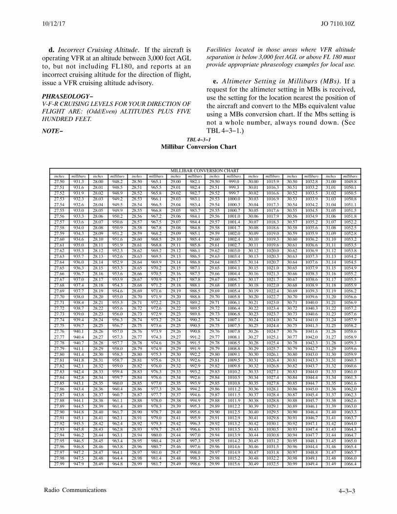
JO 7110.10Z10/12/17
4−3−3Radio Communications
d. Incorrect Cruising Altitude. If the aircraft isoperating VFR at an altitude between 3,000 feet AGLto, but not including FL180, and reports at anincorrect cruising altitude for the direction of flight,issue a VFR cruising altitude advisory.
PHRASEOLOGY−V-F-R CRUISING LEVELS FOR YOUR DIRECTION OFFLIGHT ARE: (Odd/Even) ALTITUDES PLUS FIVEHUNDRED FEET.
NOTE−
Facilities located in those areas where VFR altitudeseparation is below 3,000 feet AGL or above FL 180 mustprovide appropriate phraseology examples for local use.
e. Altimeter Setting in Millibars (MBs). If arequest for the altimeter setting in MBs is received,use the setting for the location nearest the position ofthe aircraft and convert to the MBs equivalent valueusing a MBs conversion chart. If the Mbs setting isnot a whole number, always round down. (SeeTBL 4−3−1.)
TBL 4−3−1
Millibar Conversion Chart
MILLIBAR CONVERSION CHARTinches millibars inches millibars inches millibars inches millibars inches millibars inches millibars inches millibars inches millibars
27.50 931.3 28.00 948.2 28.50 965.1 29.00 982.1 29.50 999.0 30.00 1015.9 30.50 1032.8 31.00 1049.827.51 931.6 28.01 948.5 28.51 965.5 29.01 982.4 29.51 999.3 30.01 1016.3 30.51 1033.2 31.01 1050.127.52 931.9 28.02 948.9 28.52 965.8 29.02 982.7 29.52 999.7 30.02 1016.6 30.52 1033.5 31.02 1050.527.53 932.3 28.03 949.2 28.53 966.1 29.03 983.1 29.53 1000.0 30.03 1016.9 30.53 1033.9 31.03 1050.827.54 932.6 28.04 949.5 28.54 966.5 29.04 983.4 29.54 1000.3 30.04 1017.3 30.54 1034.2 31.04 1051.127.55 933.0 28.05 949.9 28.55 966.8 29.05 983.7 29.55 1000.7 30.05 1017.6 30.55 1034.5 31.05 1051.527.56 933.3 28.06 950.2 28.56 967.2 29.06 984.1 29.56 1001.0 30.06 1017.9 30.56 1034.9 31.06 1051.827.57 933.6 28.07 950.6 28.57 967.5 29.07 984.4 29.57 1001.4 30.07 1018.3 30.57 1035.2 31.07 1052.227.58 934.0 28.08 950.9 28.58 967.8 29.08 984.8 29.58 1001.7 30.08 1018.6 30.58 1035.6 31.08 1052.527.59 934.3 28.09 951.2 28.59 968.2 29.09 985.1 29.59 1002.0 30.09 1019.0 30.59 1035.9 31.09 1052.827.60 934.6 28.10 951.6 28.60 968.5 29.10 985.4 29.60 1002.4 30.10 1019.3 30.60 1036.2 31.10 1053.227.61 935.0 28.11 951.9 28.61 968.8 29.11 985.8 29.61 1002.7 30.11 1019.6 30.61 1036.6 31.11 1053.527.62 935.3 28.12 952.3 28.62 969.2 29.12 986.1 29.62 1003.0 30.12 1020.0 30.62 1036.9 31.12 1053.827.63 935.7 28.13 952.6 28.63 969.5 29.13 986.5 29.63 1003.4 30.13 1020.3 30.63 1037.3 31.13 1054.227.64 936.0 28.14 952.9 28.64 969.9 29.14 986.8 29.64 1003.7 30.14 1020.7 30.64 1037.6 31.14 1054.527.65 936.3 28.15 953.3 28.65 970.2 29.15 987.1 29.65 1004.1 30.15 1021.0 30.65 1037.9 31.15 1054.927.66 936.7 28.16 953.6 28.66 970.5 29.16 987.5 29.66 1004.4 30.16 1021.3 30.66 1038.3 31.16 1055.227.67 937.0 28.17 953.9 28.67 970.9 29.17 987.8 29.67 1004.7 30.17 1021.7 30.67 1038.6 31.17 1055.527.68 937.4 28.18 954.3 28.68 971.2 29.18 988.1 29.68 1005.1 30.18 1022.0 30.68 1038.9 31.18 1055.927.69 937.7 28.19 954.6 28.69 971.6 29.19 988.5 29.69 1005.4 30.19 1022.4 30.69 1039.3 31.19 1056.227.70 938.0 28.20 955.0 28.70 971.9 29.20 988.8 29.70 1005.8 30.20 1022.7 30.70 1039.6 31.20 1056.627.71 938.4 28.21 955.3 28.71 972.2 29.21 989.2 29.71 1006.1 30.21 1023.0 30.71 1040.0 31.21 1056.927.72 938.7 28.22 955.6 28.72 972.6 29.22 989.5 29.72 1006.4 30.22 1023.4 30.72 1040.3 31.22 1057.227.73 939.0 28.23 956.0 28.73 972.9 29.23 989.8 29.73 1006.8 30.23 1023.7 30.73 1040.6 31.23 1057.627.74 939.4 28.24 956.3 28.74 973.2 29.24 990.2 29.74 1007.1 30.24 1024.0 30.74 1041.0 31.24 1057.927.75 939.7 28.25 956.7 28.75 973.6 29.25 990.5 29.75 1007.5 30.25 1024.4 30.75 1041.3 31.25 1058.227.76 940.1 28.26 957.0 28.76 973.9 29.26 990.8 29.76 1007.8 30.26 1024.7 30.76 1041.6 31.26 1058.627.77 940.4 28.27 957.3 28.77 974.3 29.27 991.2 29.77 1008.1 30.27 1025.1 30.77 1042.0 31.27 1058.927.78 940.7 28.28 957.7 28.78 974.6 29.28 991.5 29.78 1008.5 30.28 1025.4 30.78 1042.3 31.28 1059.327.79 941.1 28.29 958.0 28.79 974.9 29.29 991.9 29.79 1008.8 30.29 1025.7 30.79 1042.7 31.29 1059.627.80 941.4 28.30 958.3 28.80 975.3 29.30 992.2 29.80 1009.1 30.30 1026.1 30.80 1043.0 31.30 1059.927.81 941.8 28.31 958.7 28.81 975.6 29.31 992.6 29.81 1009.5 30.31 1026.4 30.81 1043.3 31.31 1060.327.82 942.1 28.32 959.0 28.82 976.0 29.32 992.9 29.82 1009.8 30.32 1026.8 30.82 1043.7 31.32 1060.627.83 942.4 28.33 959.4 28.83 976.3 29.33 993.2 29.83 1010.2 30.33 1027.1 30.83 1044.0 31.33 1061.027.84 942.8 28.34 959.7 28.84 976.6 29.34 992.6 29.84 1010.5 30.34 1027.4 30.84 1044.4 31.34 1061.327.85 943.1 28.35 960.0 28.85 977.0 29.35 993.9 29.85 1010.8 30.35 1027.8 30.85 1044.7 31.35 1061.627.86 943.4 28.36 960.4 28.86 977.3 29.36 994.2 29.86 1011.2 30.36 1028.1 30.86 1045.0 31.36 1062.027.87 943.8 28.37 960.7 28.87 977.7 29.37 994.6 29.87 1011.5 30.37 1028.4 30.87 1045.4 31.37 1062.327.88 944.1 28.38 961.1 28.88 978.0 29.38 994.9 29.88 1011.9 30.38 1028.8 30.88 1045.7 31.38 1062.627.89 944.5 28.39 961.4 28.89 978.3 29.39 995.3 29.89 1012.2 30.39 1029.1 30.89 1046.1 31.39 1063.027.90 944.8 28.40 961.7 28.90 978.7 29.40 995.6 29.90 1012.5 30.40 1029.5 30.90 1046.4 31.40 1063.327.91 945.1 28.41 962.1 28.91 979.0 29.41 995.9 29.91 1012.9 30.41 1029.8 30.91 1046.7 31.41 1063.727.92 945.5 28.42 962.4 28.92 979.3 29.42 996.3 29.92 1013.2 30.42 1030.1 30.92 1047.1 31.42 1064.027.93 945.8 28.43 962.8 28.93 979.7 29.43 996.6 29.93 1013.5 30.43 1030.5 30.93 1047.4 31.43 1064.327.94 946.2 28.44 963.1 28.94 980.0 29.44 997.0 29.94 1013.9 30.44 1030.8 30.94 1047.7 31.44 1064.727.95 946.5 28.45 963.4 28.95 980.4 29.45 997.3 29.95 1014.2 30.45 1031.2 30.95 1048.1 31.45 1065.027.96 946.8 28.46 963.8 28.96 980.7 29.46 997.6 29.96 1014.6 30.46 1031.5 30.96 1044.4 31.46 1065.427.97 947.2 28.47 964.1 28.97 981.0 29.47 998.0 29.97 1014.9 30.47 1031.8 30.97 1048.8 31.47 1065.727.98 947.5 28.48 964.4 28.98 981.4 29.48 998.3 29.98 1015.2 30.48 1032.2 30.98 1049.1 31.48 1066.027.99 947.9 28.49 964.8 28.99 981.7 29.49 998.6 29.99 1015.6 30.49 1032.5 30.99 1049.4 31.49 1066.4

JO 7110.10Z 10/12/17
4−3−4 Radio Communications
4−3−6. RADIO COMMUNICATIONSTRANSFER
Transfer radio communications by specifying thefollowing:
a. The name of the facility to be contacted and thefrequency.
PHRASEOLOGY−CONTACT (name of facility) ON (frequency).
b. In situations where an aircraft will continue tocommunicate with your facility, use the following:
PHRASEOLOGY−CONTACT (name of service) ON (frequency).
4−3−7. ATC CLEARANCES, ADVISORIES,OR REQUESTS
a. Notify ATC via interphone of a pilot’s requestfor clearance and include the departure anddestination airports and, if appropriate, departingrunway and time in the request. Forward pilotrequests to execute the Visual Climb Over Airport(VCOA) procedure to ATC. Relay, verbatim, ATCclearances, advisories, and requests received from thecontrol facility. Give a time check to the nearestquarter minute when relaying a clearance thatincludes a release or void time.
NOTE−For ATC clearances, “verbatim” means exact controlinstructions in the format stated in FAA Order JO 7110.65,Air Traffic Control, Chapter 4, Section 2, Clearances, andSection 3, Departure Procedures.
PHRASEOLOGY−Aircraft on the ground:
(ARTCC facility’s name) Center FLIGHT DATA,CLEARANCE REQUESTor
(Facility) RADIO, CLEARANCE REQUEST.
After go−ahead from ATC,
(Aircraft identification) DEPARTING (airport),RUNWAY (number if applicable) DESTINATION (fix orairport). (If applicable), CAN BE OFF AT (time).
Aircraft airborne:
(Facility) RADIO, CLEARANCE REQUEST.
After go−ahead from ATC:
(Aircraft identification), (position), (altitude), (route),AND (destination).
b. Prefix all ATC clearances, advisories, orrequests with the appropriate phrase “A-T-CCLEARS,” “A-T-C ADVISES,” etc.
c. When issuing information, relaying clearances,or instructions, ensure acknowledgement by thepilot.
d. If altitude, heading, or other items are read backby the pilot, ensure the readback is correct. Ifincorrect or incomplete, make corrections asappropriate.
NOTE−Pilots may acknowledge clearances, instructions, orinformation by using “Wilco,” “Roger,” “Affirmative,”or other appropriate words or remarks.REFERENCE
PCG.
4−3−8. DEPARTURE REPORTS
a. When an IFR aircraft reports airborne or isobserved airborne, transmit the aircraft identificationand departure time to the control facility from whichthe clearance was received.
PHRASEOLOGY−(Facility) RADIO. DEPARTURE. (Aircraftidentification), (time).
NOTE−1. This includes known VFR departure times of aircraftwhich are to obtain IFR clearances when airborne.
2. The requirement for transmitting departure reportsmay be omitted if requested by the IFR control facility,provided the procedures are specified in a Letter ofAgreement.
b. When an aircraft which has filed an IFR flightplan requests a VFR departure, facilitate the requestas follows:
1. If the facility/sector responsible for issuingthe clearance is unable to issue a clearance, inform thepilot and suggest that the delay be taken on theground. If the pilot insists upon taking off VFR andobtaining an IFR clearance in the air, relay the pilot’sintentions and, if possible, the VFR departure time tothe facility/sector holding the flight plan.
2. After obtaining approval from the facility/sector responsible for issuing the IFR clearance, anaircraft planning IFR flight may be authorized to
3/15/077110.65R CHG 2JO 7110.10Z CHG 3 2/28/19

JO 7110.10Z10/12/17
4−3−5Radio Communications
depart VFR. Inform the pilot of the proper frequencyand, if appropriate, where or when to contact thefacility responsible for issuing the clearance.
(a) When requesting:
PHRASEOLOGY−(Facility) RADIO. (Aircraft identification), REQUESTV-F-R DEPARTURE.
(b) When relaying to aircraft:
PHRASEOLOGY−A-T-C ADVISES (aircraft identification) V-F-RDEPARTURE APPROVED. CONTACT (facility) ON(frequency) AT (location or time, if required) FORCLEARANCE.
(c) Relaying to control facility:
PHRASEOLOGY−(Facility) RADIO. (Aircraft identification) DEPARTEDV-F-R AT (time).
4−3−9. IFR FLIGHT PROGRESS REPORTS
Relay to the appropriate ATC facility the aircraftidentification, position, time, altitude, estimate ofnext reporting point, name of subsequent reportingpoint, and any pilot remarks or requests includingamended flight plan data.
PHRASEOLOGY−(Facility) RADIO. PROGRESS. (Aircraft identification),(position), (altitude), (time) (name and estimate of nextreporting point) (name of subsequent reporting point)(pilot’s remarks).
4−3−10. ARRIVAL/MISSED APPROACHREPORTS
Relay to the appropriate ATC facility, by the mostexpeditious means available, the time that an IFRaircraft lands, cancels, or executes a missed approach,and intentions, if known.
4−3−11. NONDELIVERY OF MESSAGES
Inform ATC when a message has not been deliveredwithin:
a. Three minutes of receipt; or
b. Three minutes after the specified delivery time;or
c. A specified cancellation time.
4−3−12. BROADCAST (BLINDTRANSMISSION) OF MESSAGES
Broadcast messages as requested by ATC. If noaccompanying transmitting instructions are received,transmit the message four times:
a. Once upon receipt; and
b. At approximately 3-minute intervals thereafter.
4−3−13. PENETRATION OF CLASS AAIRSPACE OR PROHIBITED/RESTRICTEDAREA
a. Penetration of Class A airspace. When a VFRaircraft’s position report indicates penetration ofClass A airspace:
1. Inform the pilot of the Class A airspacepenetration and request intentions.
PHRASEOLOGY−YOU ARE IN CLASS A AIRSPACE. AN A-T-CCLEARANCE IS REQUIRED. REQUEST YOURINTENTIONS.
2. Inform the control facility immediately.
3. Relay ATC instructions.
b. Penetration of PROHIBITED/RESTRICTEDAREA. When an aircraft report indicates penetrationof a prohibited/restricted area:
1. Inform the pilot.
PHRASEOLOGY−YOU ARE IN A PROHIBITED/RESTRICTED AREA,AUTHORIZATION IS REQUIRED. REQUEST YOURINTENTIONS.
2. Inform the control facility immediately.Relay ATC instructions.
2/28/19 JO 7110.10Z CHG 3


JO 7110.10Z10/12/17
4−4−1Airport Advisory Services (Alaska Only)
Section 4. Airport Advisory Services (Alaska Only)
4−4−1. TYPES OF AIRPORT ADVISORYSERVICES
Airport advisory services are provided at airportswithout an operating control tower that have certifiedautomated weather reporting via voice capability.The types of service depend upon the location of theFSS and communications capabilities. There arethree types:
a. Local airport advisory (LAA) is a serviceprovided by facilities that are located on the landingairport.
b. Remote airport advisory (RAA) is a remoteservice which may be provided by facilities that arenot located on the landing airport.
NOTE−LAA/RAA both have:
1. Ground-to-air communication on the com-mon traffic advisory frequency (CTAF).
2. Automated weather reporting with voicebroadcasting.
3. A continuous automated weather datadisplay.
4. Other continuous direct reading instruments,or manual observations available to the specialist.
c. Remote airport information service (RAIS) is atemporary service provided by facilities which arenot located on the landing airport but have:
1. Communication capability.
2. Automated weather reporting available to thepilot at the landing airport.
NOTE−FAA policy requires pilots to access the current automatedweather prior to requesting any remote ATC services atnon-towered airports. It is the pilot’s responsibility tocomply with the Federal Aviation Regulations (FARs) iflanding clearance is required.
4−4−2. GENERAL
a. If a pilot asks for airport advisory services at anairport where the requested service is not availablebut one of the services is available, inform the pilot
about what service is available, and provide theappropriate service.
PHRASEOLOGY−(Airport name) AIRPORT ADVISORY IS NOTAVAILABLE. REMOTE AIRPORT INFORMATION...
b. At airports with commissioned automatedweather with continuous automated voice capability,instruct the pilot to monitor the automated broadcastand advise intentions.
PHRASEOLOGY−MONITOR (location) AUTOMATED WEATHER(frequency). ADVISE INTENTIONS.
1. When the pilot indicates receipt of automatedweather, provide the appropriate non-weatherelements.
2. If the pilot reports the automated weather isout of service, provide the last reported weatheravailable and the appropriate non-weather elements.
c. Advise the pilot that the requested airportadvisory/RAIS service is not available. ProvideCTAF frequency and/or the automated weatherfrequency, when available. When not available, issuethe last known surface condition and altimeter.
PHRASEOLOGY−(Airport name) AIRPORT ADVISORY or AIRPORTINFORMATION NOT AVAILABLE. CONTACT (airportname) CTAF (frequency).
d. During initial contact, if the pilot indicatesreceipt of automated weather, provide only theappropriate non-weather elements. Do not provideweather information unless specifically requested bythe pilot or a special report is transmitted.
EXAMPLE−RAIS:Pilot - “Green Bay radio, Cessna 12RG, ten northeast,landing Eau Claire, request airport information, I havethe automated weather.”
FSS - “Cessna 12RG, Eau Claire airport information,your traffic is a Cessna 172 entering downwind and aConvair 660 reported on final, both one minute ago.There is an airport maintenance vehicle .
e. If additional pilots initiate contact a short timeafter airport advisory services were provided,determine if the new pilot(s) copied the informationwhen it was provided.

JO 7110.10Z 10/12/17
4−4−2 Airport Advisory Services (Alaska Only)
1. If the new pilot responds in the affirmative,do not repeat the information.
2. If the new pilot acknowledges the airportadvisory information and then requests specificinformation, provide only the information requested.
NOTE−The intent is to reduce frequency clutter while insuringthat the pilots are aware of the situation as it changes.
f. Final Guard is a service provided in conjunctionwith airport advisory only during periods ofsignificant and fast changing weather conditions thatmay affect landing and takeoff operations.
g. Where AFIS is available, confirm receipt of thecurrent AFIS information if the pilot does notinitially state the appropriate AFIS code. Issue thecurrent AFIS information to pilots who are unable toreceive the AFIS or pilots that do not have theinformation.
EXAMPLE−“Verify you have information ALPHA.”
h. If the pilot requests special VFR clearance,provide the appropriate elements and follow theprocedures in Chapter 4, Section 5, Special VFROperations.
4−4−3. AIRPORT ADVISORY/RAISELEMENTS AND PHRASEOLOGY
a. State the airport name and the type of servicebeing provided: airport advisory or airportinformation.
EXAMPLE−(Airport name), AIRPORT ADVISORY . . .
Or
(Airport name), AIRPORT INFORMATION . . .
NOTE−At FSS facilities with AFIS equipment, if an aircraft hasacknowledged receipt of the AFIS message, trafficadvisories and additional information need not bepreceded by the phrase “(Airport name) AIRPORTADVISORY.”
b. Provide the following information as needed tobest serve the current traffic situation. Do not approveor disapprove simulated instrument approaches.
1. Wind direction and speed.
2. Favored or designated runway is a serviceprovided in conjunction with an airport advisory. Thespecialist must check the current wind data andprovide the favored or designated runway informa-tion as follows:
(a) For takeoff and landing operations statethe runway most nearly aligned into the wind.
(b) Inform the pilot when the current winddirection is varying enough that the selection of thefavored runway may be affected, when there is morethan 10 knots between peaks and lulls, or the pilot hasrequested the information.
(c) If there is no wind, state the runwaycurrently in use, the runway favored by a shortertaxiway, or other local consideration.
(d) When airport management has designateda runway to be used under certain wind or otherconditions (and has informed the FSS in writing)issue runway information accordingly.
(e) If the majority of the traffic has been usinga runway other than the favored or designatedrunway, advise the pilot.
EXAMPLE−Landing airport has runways 27 (longer) and 32 with mostpilots utilizing the shorter runway “WIND VARIABLEBETWEEN TWO EIGHT ZERO AND THREE FOURZERO AT ONE FIVE GUSTS TWO EIGHT, FAVOREDRUNWAY THREE TWO.”
(f) When a pilot advises he/she will use arunway other than the favored or the designatedrunway, inform all known concerned traffic.
PHRASEOLOGY−ATTENTION ALL AIRCRAFT. (Aircraft type)DEPARTING/LANDING RUNWAY (number).
(g) If a pilot requests the distance between anintersection and the runway end, furnish measureddata from the local airport intersection takeoffdiagram or other appropriate sources.
(h) The favored or designated runway isnever provided with RAIS.
3. Altimeter Setting.
(a) Airport Advisory: Apply special proced-ures when the altimeter setting is more than31.00 inches Hg. Stations with the capability ofreading altimeter settings above 31.00 inches Hgmust issue altimeter settings.

JO 7110.10Z10/12/17
4−4−3Airport Advisory Services (Alaska Only)
PHRASEOLOGY−ALTIMETER IN EXCESS OF THREE ONE ZERO ZERO.HIGH PRESSURE ALTIMETER SETTINGPROCEDURES ARE IN EFFECT. RECOMMEND YOUSET ALTIMETER TO THREE ONE ZERO ZERO ENROUTE.”
(b) RAIS. Do not provide the altimeter unlessspecifically requested. Then, provide the altimeterfrom the last official weather report.
4. Traffic. Information about observed orreported traffic, which may constitute a collisionhazard. This may include positions of aircraft inflightand/or aircraft and vehicles operating on the airport.
PHRASEOLOGY−TRAFFIC (Aircraft type), (position), (minutes) AGO.
5. Braking action/NOTAM. Furnish brakingaction reports as received from pilots to all aircraft asfollows:
(a) Describe braking action using the terms“good,” “good to medium,” “medium,” “medium topoor,” “poor,” or “nil.” If the pilot reports brakingaction in other than the approved terms, ask them tocategorize braking action in these terms.
(b) When known, include the type of aircraftor vehicle from which the report is received.
EXAMPLE−“Braking action poor.”
“Braking action medium, reported by a CessnaFour−Twenty−One.”
(c) If the braking action report affects only aportion of a runway, obtain enough information fromthe pilot to describe braking action in terms easilyunderstood by other pilots.
EXAMPLE−“Braking action poor first half of Runway Six, reported bya Gulfstream Two.”
“Braking action medium Runway Two−Seven, reported bya Boeing Seven Thirty−Seven.”
NOTE−Descriptive terms, such as first/last half of the runway,should normally be used rather than landmarkdescriptions, such as opposite the fire station, south of ataxiway.
6. NOTAM. NOTAMs concerning localNAVAIDs and local field conditions/airspaceconditions pertinent to flight, for example, localNAVAIDs, TFRs.
EXAMPLE−“All runways covered by packed snow 6 inches deep.”
7. Weather. When the pilot does not have theweather conditions, issue the last reported or knownweather information as follows:
(a) Airport Advisory/RAIS:
(1) Wind direction and speed.
(2) Altimeter (except RAIS).
(3) Ceiling and visibility to VFR aircraftwhen less than basic VFR conditions exist.
(4) Visibility to VFR aircraft when it is lessthan three miles in any quadrant.
(5) Touchdown runway visual range(RVR)/runway visibility value (RVV) for the runwayin use where RVR/RVV readout equipment is locatedat the workstation providing the service.
(6) To IFR aircraft executing an instrumentapproach or departure and to the appropriate controlfacility when visibility is less than 3 miles or whenthe ceiling is less than 1,000 feet or below the highestcircling minimum, whichever is greater.
8. Weather advisory alert. Provide in accord-ance with subpara 4−3−5a.
PHRASEOLOGY−(Advisory description) IS CURRENT FOR (condition)OVER (area).
9. Density Altitude.
(a) Facilities at airports with field elevationsof 2,000 feet MSL or higher, transmit a densityaltitude advisory to departing general aviationaircraft whenever the temperature reaches the criteriacontained in TBL 2−2−1.
PHRASEOLOGY−CHECK DENSITY ALTITUDE.
(b) Omit this advisory if pilot states thecomputation has been done or if the specialist isaware that a density altitude computation for thataircraft was included in the preflight briefing.
10. Wake Turbulence. Issue cautionary inform-ation to any aircraft if in your judgment waketurbulence may have an adverse effect on it.
PHRASEOLOGY−CAUTION, WAKE TURBULENCE (traffic information).
JO 7110.10Z 10/12/17
4−4−4 Airport Advisory Services (Alaska Only)
NOTE−Wake turbulence may be encountered by aircraft in flightas well as when operating on the airport movement area.Because wake turbulence is unpredictable, air trafficpersonnel are not responsible for anticipating itsexistence or effect.
11. Final Guard is a wind and altimetermonitoring service provided in conjunction withairport advisory during periods of significant and/orfast changing weather conditions that may affectlanding and takeoff operations. The specialist mustmonitor the remote display of the current wind andaltimeter. Provide Final Guard as follows:
(a) When the pilot reports “On final” or“Taking the active runway,” the specialist mustprovide the current wind direction, speed, andaltimeter.
(b) If during the landing or takeoff operationconditions change and, in the specialist’s opinion, thechanging information might be useful to the pilot, thespecialist must broadcast the new wind and/oraltimeter information in the blind.
(c) Pilots will not be required or expected toacknowledge the broadcast.
EXAMPLE−“N12RG, Wind (direction) at (speed).”
NOTE−Final Guard is never provided with RAIS.
12. Upon request, provide runway conditioncodes (RwyCC) as received from airport manage-ment to aircraft as follows: State the runway numberfollowed by the runway condition code for each of thethree runway zones and the time of the report in UTC.Issue FICON NOTAMs upon pilot request.
EXAMPLE−“Runway two seven, condition code two, two, one at onezero one eight ZULU.”
(a) Issue the runway surface condition and/orthe runway condition reading (RCR), if provided, toall U.S. Air Force (USAF) and Air National Guard(ANG) aircraft. Issue the RCR to other aircraft uponrequest.
EXAMPLE−“Ice on runway, R-C-R zero five, patchy.”
NOTE−USAF has established RCR procedures for determiningthe average deceleration readings of runways underconditions of water, slush, ice, or snow. The use of RCR
code is dependent upon the pilot’s having a “stoppingcapability chart” specifically applicable to his/heraircraft. USAF offices furnish RCR information atairports serving USAF and ANG aircraft.
4−4−4. CHARTS
Keep charts depicting runways, local taxi routes,intersection takeoff information, airport trafficpatterns, and instrument approach proceduresconvenient to the position that provides airportadvisory service.
4−4−5. AUTHORIZED FREQUENCIES
a. Airport Advisory:
1. Provide airport advisory service on theappropriate discrete frequency at non-toweredlocations and on the tower local control frequency atan airport with a part-time tower when that facility isnot operating.
2. If a pilot calls on another frequency, issueadvisories on the frequency to which the pilot islistening, in addition to the appropriate AirportAdvisory frequency.
3. Encourage the pilot to guard the airportadvisory frequency or tower local control frequencywithin a 10-mile radius of the airport.
NOTE−In situations where the inflight position is split, advisepilot of appropriate frequency to obtain AirportAdvisory/RAIS.
PHRASEOLOGY−FOR FURTHER ADVISORY SERVICE AT (airportname), MONITOR (frequency) WITHIN ONE ZEROMILES.
b. RAIS:
1. Provide RAIS on the existing discretefrequency located at the remote airport.
2. If a pilot calls and appears to be unaware thatRAIS is available, offer the service.
3. If a pilot calls on another frequency, issueadvisories on the frequency the pilot is listening, inaddition to the appropriate airport advisory fre-quency.
4. If RAIS is requested when it is not offered,inform the pilot that the service is not available andfollow para 4−4−2c.
NOTE−This service is only provided at remote airports that have

JO 7110.10Z10/12/17
4−4−5Airport Advisory Services (Alaska Only)
an existing discrete communications capability betweenthe airport and the flight service station serving the
airport and a NOTAM D announcing the availability ofthe service is in effect.
4−4−6. TRAFFIC CONTROL
When there is no control tower in operation and apilot appears unaware of this fact, inform him/her asfollows:
PHRASEOLOGY−NO CONTROL TOWER IN OPERATION.
4−4−7. AIRCRAFT EQUIPMENT CHECKS
When requested, provide observed information.
EXAMPLE−Landing gear appears to be down and in place.


JO 7110.10Z10/12/17
4−5−1Special VFR Operation
Section 5. Special VFR Operation
4−5−1. AUTHORIZATION
a. Special VFR (SVFR) operations in weatherconditions less than VFR minima are authorized:
1. For helicopters and fixed-wing aircraft at anylocation not prohibited by 14 CFR Part 91,Appendix D, Section 3, or when an exception to14 CFR Part 91, Appendix D, Section 3, has beengranted and an associated letter of agreementestablished.
REFERENCE−14 CFR Part 91, Appendix D, Section 3, Locations at which fixed-wingSpecial VFR operations are prohibited.
2. Only within surface areas.
3. Only when requested by the pilot.
b. When the primary airport is reporting VFR,SVFR operations may be authorized for aircrafttransiting surface areas when the pilot advises theinability to maintain VFR.
NOTE−Control facilities must always retain SVFR operationsauthority when IFR operations are being conducted insurface areas.
4−5−2. REQUESTS FOR SPECIAL VFRCLEARANCE
a. Transmit SVFR clearances only for operationswithin surface areas on the basis of weatherconditions. If weather conditions are not reported,transmit an SVFR clearance whenever a pilot advisesunable to maintain VFR and requests an SVFRclearance, provided the pilot reports having at least1-mile flight visibility.
PHRASEOLOGY−ATC CLEARS (aircraft identification) TO ENTER/OUTOF/THROUGH (name) SURFACE AREA
and if required,
(direction) OF (name) AIRPORT (specified routing), and
MAINTAIN SPECIAL V-F-R CONDITIONS,
and if required,
AT OR BELOW (altitude below 10,000 feet MSL),
ATC CLEARS (aircraft identification) (coded arrival ordeparture procedure) ARRIVAL/DEPARTURE,(additional instructions as required).
b. Transmit clearance for local SVFR operationsfor a specified period (series of takeoffs and landings,etc.) upon request if the aircraft can be recalled whentraffic or weather conditions require. Letters ofagreement may be established.
PHRASEOLOGY−LOCAL SPECIAL V-F-R OPERATIONS IN THEIMMEDIATE VICINITY OF (name) AIRPORT AREAUTHORIZED UNTIL (time). MAINTAIN SPECIALV-F-R CONDITIONS.
c. If an aircraft operating under visual flight rulesattempts to enter, depart, or operate within surfaceareas contrary to the provisions of 14 CFR Section91.157 (visual flight rules), ensure the pilot is awareof the current weather conditions. Provide thefollowing information:
1. At airports with commissioned automatedweather with continuous automated voice capability,instruct the pilot to monitor the automated broadcastand advise intentions.
PHRASEOLOGY−MONITOR (location) AUTOMATED WEATHER(frequency). ADVISE INTENTIONS.
2. At airports without a commissionedautomated weather, or, if the pilot is unable to receivethe automated weather broadcast, issue the mostcurrent weather report available. Advise the pilot thatthe weather is below VFR minima, and request thepilot’s intentions.
PHRASEOLOGY−(Location) WEATHER, CEILING (height), VISIBILITY(miles). (Location) SURFACE AREA IS BELOW V-F-RMINIMA. AN ATC CLEARANCE IS REQUIRED.ADVISE INTENTIONS.
NOTE−Helicopters performing hover taxiing operations(normally not above 10 feet) within the boundary of theairport are considered to be taxiing aircraft.
d. At a pilot’s request, issue a SVFR clearance, ifappropriate, when a SVFR letter of agreement existsbetween an FSS and the control facility. If noagreement exists, request clearance from the control

JO 7110.10Z 10/12/17
4−5−2 Special VFR Operation
facility. State the aircraft’s location and route offlight.
PHRASEOLOGY−(Facility name) RADIO. REQUEST SPECIAL V-F-RCLEARANCE (aircraft identification) (direction) OF(location) AIRPORT (specified routing) TO ENTER/OUTOF/THROUGH (name) AIRPORT (specified routing).
NOTE−IFR aircraft normally have priority over SVFR aircraft.
1. If the pilot is operating outside surface areaand requests SVFR clearance, issue the clearance orif unable, advise the pilot to maintain VFR outsidesurface area and to standby for clearance.
PHRASEOLOGY−MAINTAIN V-F-R OUTSIDE (location) SURFACEAREA. STANDBY FOR CLEARANCE.
2. When an aircraft requests a SVFR clearanceto enter surface area during periods of SVFR activity,instruct the pilot to maintain VFR conditions outsidesurface area pending arrival/recall/departure ofSVFR operations.
PHRASEOLOGY−MAINTAIN V-F-R CONDITIONS OUTSIDE OF THE(location) SURFACE AREA PENDINGARRIVAL/RECALL/DEPARTURE OF IFR/SPECIALV-F-R AIRCRAFT.
3. If the pilot is operating inside the surface areaand requests an SVFR clearance, advise the pilot tomaintain VFR and standby for clearance.
PHRASEOLOGY−MAINTAIN V-F-R. STANDBY FOR CLEARANCE.
e. Suspend SVFR operations when necessary tocomply with instructions contained in subpara 4-5-4bor when requested by the control facility.
PHRASEOLOGY−SPECIAL V-F-R AUTHORIZATION DISCONTINUED.RETURN TO AIRPORT OR DEPART SURFACE AREA.ADVISE INTENTIONS.
After response:
REPORT LANDING COMPLETED/CLEAR SURFACEAREA.
4−5−3. VISIBILITY BELOW 1 MILE
a. When the ground visibility is officially reportedat an airport as less than 1 mile, treat requests for
SVFR operations at that airport by other thanhelicopters as follows:
NOTE−14 CFR Part 91 does not prohibit helicopter Special VFRflights when visibility is less than 1 mile.
1. Inform departing aircraft that ground visibil-ity is less than 1 mile and that a clearance cannot beissued.
PHRASEOLOGY−(Location) VISIBILITY (value). A-T-C UNABLE TOISSUE DEPARTURE CLEARANCE.
2. Inform arriving aircraft operating outside ofthe surface area that ground visibility is less than1 mile and, unless an emergency exists, a clearancecannot be issued.
PHRASEOLOGY−(Location) VISIBILITY (value). A-T-C UNABLE TOISSUE ENTRY CLEARANCE UNLESS ANEMERGENCY EXISTS.
3. Inform arriving aircraft operating within thesurface area that ground visibility is less than 1 mileand request the pilot’s intentions. Relay the pilot’sresponse to the control facility immediately.
PHRASEOLOGY−(Location) VISIBILITY (value). ADVISE INTENTIONS.
b. When weather conditions are not officiallyreported at an airport and the pilot advises the flightvisibility is less than 1 mile, treat request for SVFRoperations at that airport by other than helicopters asfollows:
NOTE−14 CFR Part 91 prescribes use of officially reportedground visibility as the governing ground visibility forVFR and SVFR operations at airports where it is providedand landing or takeoff flight visibility where it is not.
1. Inform departing aircraft that a clearancecannot be issued.
PHRASEOLOGY−UNABLE TO ISSUE DEPARTURE CLEARANCE.
2. Inform arriving aircraft operating outside thesurface area that unless an emergency exists, aclearance cannot be issued.
PHRASEOLOGY−ATC UNABLE TO ISSUE ENTRY CLEARANCE UNLESSAN EMERGENCY EXISTS.
3. Request intentions of arriving aircraftoperating within surface areas. Relay the pilot’sresponse to the control facility immediately.

JO 7110.10Z10/12/17
4−5−3Special VFR Operation
PHRASEOLOGY−ADVISE INTENTIONS.
c. Transmit a clearance to scheduled air carrieraircraft to conduct operations if ground visibility isnot less than 1/2 mile.
d. Transmit a clearance to an aircraft to fly throughsurface area if the pilot reports flight visibility is atleast 1 statute mile.
4−5−4. PREDESIGNED SPECIAL VFRCLEARANCES
Transmit predesigned SVFR clearances only duringthose periods authorized by the control facility.
NOTE−The control facility may rescind this authorization at anytime.
a. Apply these procedures only to aircraftequipped with a functioning two-way radio. Refer allrequests for no-radio SVFR operations to the controlfacility.
b. Transmit clearances so that only one aircraft ata time operates in surface area unless:
1. Otherwise authorized by a letter of agreementbetween the control facility and the FSS.
2. A pilot requests and all pilots agree that theywill maintain visual separation while operating insurface area.
PHRASEOLOGY−MAINTAIN VISUAL SEPARATION FROM (aircraft type).


JO 7110.10Z10/12/17
5−1−1General
Chapter 5. Emergency Services
Section 1. General
5−1−1. EMERGENCY DETERMINATION
a. Because of the infinite variety of possibleemergency situations, specific procedures cannot beprescribed. However, when it is believed that anemergency exists or is imminent, take a course ofaction which appears to be most appropriate under thecircumstances and which most nearly conforms to theinstructions in this manual.
b. An emergency can be either a DISTRESS orURGENCY condition, as defined in thePilot/Controller Glossary.
NOTE−A pilot who encounters a DISTRESS condition maydeclare an emergency by beginning the initialcommunication with the word MAYDAY, preferablyrepeated three times. For an URGENCY condition, theword PAN-PAN may be used in the same manner.
c. If the words MAYDAY or PAN-PAN are notused, and there is doubt that a situation constitutes anemergency or potential emergency, handle it asthough it is an emergency.
d. Consider an aircraft emergency exists andinform the appropriate control facility when:
1. An emergency is declared by any of thefollowing:
(a) The pilot.
(b) Facility personnel.
(c) Officials responsible for the operation ofthe aircraft.
2. Reports indicate that the aircraft’s operatingefficiency is so impaired that a forced landing maybe/is necessary.
3. Reports indicate the crew has abandoned theaircraft or is about to do so.
4. Intercept or escort services are requested.
5. The need for ground rescue appears likely.
6. An Emergency Locator Transmitter (ELT)signal is heard or reported.
REFERENCE−FAA Order 7110.10, Para 5−1−2c, ResponsibilityFAA Order 7110.10, Para 5−2−8, Emergency Locator Transmitter (ELT)Signals
5−1−2. RESPONSIBILITY
a. If in communication with an aircraft in distress,handle the emergency, and coordinate and direct theactivities of assisting facilities. Transfer thisresponsibility to another facility only when betterhandling of the emergency will result.
b. Upon receipt of information about an aircraft indistress, forward detailed data to the appropriatecontrol facility in whose area the emergency exists.
NOTE−Notifying the appropriate control facility about a VFRaircraft emergency allows provision of IFR separation ifconsidered necessary.
c. The ARTCC is responsible for consolidation ofall pertinent ELT signal information. Notify theARTCC of all heard or reported ELT signals.
5−1−3. OBTAINING INFORMATION
Obtain enough information to handle the emergencyintelligently. Base decisions about the type ofassistance needed on information and requestsreceived from the pilot. 14 CFR Part 91 authorizes thepilot to determine a course of action.
5−1−4. COORDINATION
a. Request assistance from other facilities as soonas possible, particularly if radar is available.
b. Coordinate efforts to the extent possible toassist any aircraft believed overdue, lost, or inemergency status.
5−1−5. PROVIDING ASSISTANCE
a. Provide maximum assistance to aircraft indistress. If the aircraft is transponder-equipped andnot on an IFR flight plan, instruct the pilot to squawkcode 7700.
PHRASEOLOGY−SQUAWK SEVEN SEVEN ZERO ZERO.

JO 7110.10Z 10/12/17
5−1−2 General
b. Enlist the service of available radar facilities.
5−1−6. RECORDING INFORMATION
Record all actions taken in the provision ofemergency assistance.
5−1−7. SAFE ALTITUDES FORORIENTATIONS
a. Providing a safe altitude, during an orientation,is advisory in nature.
b. Safe altitude computations, once the aircraftposition is known, are as follows:
1. Locate the maximum elevation figure on theappropriate VFR sectional chart.
2. To the maximum elevation figure,
(a) Add 1,000 feet over non-mountainousterrain; or
(b) Add 2,000 feet over mountainous terrain.
3. Designated mountainous/non-mountainousareas are found in Title 14 CFR, Part 95, subpart b.

JO 7110.10Z10/12/17
5−2−1Operations
Section 2. Operations
5−2−1. INFORMATION REQUIREMENTS
a. Start assistance as soon as enough informationhas been obtained upon which to act. Informationrequirements will vary, depending on the existingsituation. Minimum required information for inflightemergencies is:
1. Aircraft identification, type, and transponder.
2. Nature of the emergency.
3. Pilot’s desires.
b. After initiating action, provide the altimetersetting, and obtain the following items or any otherpertinent information from the pilot or aircraftoperator as necessary:
1. Aircraft altitude.
2. Fuel remaining, in time.
3. Pilot-reported weather.
4. Pilot capability for IFR flight.
5. Time and place of last known position.
6. Heading since last known position.
7. Airspeed.
8. Navigation equipment capability.
9. NAVAID signals received.
10. Visible landmarks.
11. Aircraft color.
12. Number of people on board.
13. Point of departure and destination.
14. Emergency equipment on board.
5−2−2. FREQUENCY CHANGES
Provide assistance on the initial contact frequency.Change frequencies only when there is a valid reason.Advise the pilot to return to the initial frequency ifunable to establish contact.
5−2−3. AIRCRAFT ORIENTATION
Orient an aircraft by the means most appropriate tothe circumstances. Recognized methods include:
a. Radar.
b. NAVAIDs.
c. Pilotage.
d. Sighting by other aircraft.
5−2−4. ALTITUDE CHANGE FORIMPROVED RECEPTION
If deemed necessary, and if weather andcircumstances permit, recommend the aircraftmaintain or increase altitude to improvecommunications or reception.
5−2−5. ALERTING CONTROL FACILITY
When an aircraft is considered to be in emergencystatus, alert the appropriate control facility, andforward the following information as available:
a. Facility/sector and position calling.
b. Flight plan, including color of aircraft, ifknown.
c. Time of last transmission received, by whom,and frequency used.
d. Last known position, estimated present posi-tion, and maximum range of flight of the aircraftbased on remaining fuel and airspeed.
e. Action taken by reporting facility and proposedaction.
f. Number of persons on board.
g. Fuel status.
h. Position of other aircraft near the aircraft’s routeof flight, when requested.
i. Whether an ELT signal has been heard orreported in the vicinity of the last known position.
j. Other pertinent information.
5−2−6. VFR AIRCRAFT IN WEATHERDIFFICULTY
If a VFR aircraft requests assistance when itencounters or is about to encounter IFR weatherconditions, request the pilot contact the appropriatecontrol facility. Inform that facility of the situation.

JO 7110.10Z 10/12/17
5−2−2 Operations
If the pilot is unable to communicate with the controlfacility, relay information and clearances.
5−2−7. AIRCRAFT POSITION PLOTS
If necessary, plot the flight path of the aircraft on achart, including position reports, predicted positions,possible range of flight, and any other pertinentinformation. Solicit the assistance of other aircraftknown to be operating near the aircraft in distress.Forward the information to the appropriate controlfacility.
5−2−8. EMERGENCY LOCATORTRANSMITTER (ELT) SIGNALS
When an ELT signal is heard or reported:
a. Notify the ARTCC, who will coordinate withthe Rescue Coordination Center (RCC).
b. If the ELT signal report was received from anairborne aircraft, attempt to obtain the followinginformation:
1. The aircraft altitude.
2. Where and when the signal was first heard.
3. Where and when maximum signal was heard.
4. Where and when signal faded or was lost.Solicit the assistance of other aircraft known to beoperating in the signal area for the same information.Relay all information obtained to the ARTCC.
c. Attempt to obtain fixes or bearings on the signaland forward any information obtained to the ARTCC.
NOTE−Fix information, in relation to a VOR or a VORTAC(radial distance), facilitates accurate ELT plotting byRCC and should be provided when possible.
d. In addition to the above, when the ELT signalstrength indicates the transmitter may be on theairport or in the vicinity, notify the on-site technicaloperations services personnel for their action.
e. Air traffic personnel must not leave theirrequired duty stations to locate an ELT signal source.
f. Attempt to locate the signal source by checkingall adjacent airports not already checked by otherATC facilities for the following information:
1. Can ELT signal be heard?
2. Does signal strength indicate transmitter maybe on airport?
3. Can attempt be made to locate and silencetransmitter?
4. Advise the results of any action taken.Forward all information obtained and action taken tothe ARTCC.
g. Notify the ARTCC if the signal source islocated and whether the aircraft is in distress, plus anyaction taken or proposed for silencing the transmitter.Request person who located signal’s source toattempt to obtain ELT make, model, etc., for relay toRCC via the ARTCC.
h. Notify the ARTCC if the signal terminates priorto location of the source.
NOTE−1. The ARTCC serves as the contact point for collectinginformation and coordinating with the RCC on all ELTsignals.
2. Operational ground testing of ELT has beenauthorized during the first 5 minutes of each hour. Toavoid confusing the tests with an actual alarm, the testingis restricted to no more than three audio sweeps.
3. Portable, handcarried receivers assigned to air trafficfacilities (where no technical operations servicespersonnel are available) may be loaned to responsibleairport personnel or local authorities to assist in locatingsignal source.
5−2−9. EXPLOSIVE CARGO
When you receive information that an emergencylanding will be made with explosive cargo aboard,inform the pilot of the safest or least congested airportareas. Relay the explosive cargo information to:
a. The emergency equipment crew.
b. The airport management.
c. The appropriate military agencies whenrequested by the pilot.
5−2−10. EXPLOSIVE DETECTION DOGHANDLER TEAMS
Take the following actions upon receipt of a pilotrequest for the location of the nearest explosivedetection K−9 team.

JO 7110.10Z10/12/17
5−2−3Operations
a. Obtain the aircraft’s identification and currentposition, and advise the person in charge of the watchof the pilot’s request.
b. Relay the pilot’s request to the FAAWashington Operations Center, AEO-100, (202)267-3333, and provide the aircraft identification andposition.
c. AEO-100 will provide the nearest location.Have AEO-100 standby while the information isrelayed to the pilot.
d. If the pilot wishes to divert to the airportlocation provided, obtain an estimated arrival timefrom the pilot, and advise the person in charge of thewatch.
e. After the aircraft destination has beendetermined, provide the estimated arrival time toAEO-100. AEO−100 will then notify the appropriateairport authority at the diversion airport. In the eventthe K-9 team is not available at this airport, AEO-100will advise the air traffic facility and provide themwith the secondary location. Relay this to the pilotconcerned for appropriate action.
REFERENCE−FAA Order JO 7210.3, Para 2-1-12, Explosives Detection K-9 Teams
5−2−11. INFLIGHT EQUIPMENTMALFUNCTIONS
When a pilot reports an inflight equipmentmalfunction, take the following action:
a. Request the nature and extent of any specialhandling desired.
NOTE−14 CFR Part 91.187 requires the pilot in command of eachaircraft operated in controlled airspace under IFR MUSTreport as soon as practical to ATC any malfunctions ofnavigational, approach, or communication equipmentoccurring in flight. This includes the degree to which thecapability of the aircraft to operate IFR in the air trafficcontrol system is impaired and the nature and extent of anyassistance desired from air traffic control.
b. Provide the maximum assistance possibleconsistent with equipment, workload, and anyspecial handling requested.
c. Relay any special handling required or beingprovided to other specialists or facilities who willsubsequently handle the aircraft.
5−2−12. MINIMUM FUEL
If an aircraft declares a state of “minimum fuel,”inform any facility to whom control jurisdiction istransferred of the minimum fuel problem and be alertfor any occurrence which might delay the aircraft enroute.
NOTE−Use of the term “minimum fuel” indicates recognition bya pilot that the fuel supply has reached a state whereuponreaching destination, any undue delay cannot beaccepted. This is not an emergency situation but merely anadvisory that indicates an emergency situation is possibleshould any undue delay occur. A minimum fuel advisorydoes not imply a need for traffic priority. Common senseand good judgment will determine the extent of assistanceto be given in minimum fuel situations. If, at any time, theremaining usable fuel supply suggests the need for trafficpriority to ensure a safe landing, the pilot should declarean emergency and report fuel remaining in minutes.
5−2−13. AIRCRAFT BOMB THREATS
a. When information is received from any sourcethat a bomb has been placed on, in, or near an aircraftfor the purpose of damaging or destroying suchaircraft, notify the supervisor or facility manager. Ifthe threat is general in nature, handle it as a suspiciousactivity. When the threat is targeted against a specificaircraft and you are in contact with that aircraft, takethe following actions as appropriate:
NOTE−1. Facility supervisors are expected to notify theappropriate offices, agencies, and operators/air carriersaccording to applicable plans, directives, FAA OrderJO 7210.3, Facility Operation and Administration, ormilitary directives.
2. Suspicious activity is covered in FAA Order JO 7610.4,Chapter 7, Hijacked/Suspicious Aircraft Reporting andProcedures. Military facilities would report a generalthreat through the chain of command or according toservice directives.
REFERENCE−FAA Order JO 7610.4, Chapter 7, Hijacked/Suspicious AircraftReporting and Procedures.
3. A specific threat may be directed at an aircraft registryor tail number, the air carrier flight number, the name ofan operator, crew member or passenger, the departure/ar-rival point or times, or combinations thereof.
1. Advise the pilot of the threat.
2. Report the threat to the Domestic EventsNetwork (DEN) Air Traffic Security Coordinator(ATSC) via (844) 432-2962 (toll−free). If unable to
2/28/19 JO 7110.10Z CHG 3

JO 7110.10Z 10/12/17
5−2−4 Operations
contact the DEN ATSC notify the TransportationSecurity Administration/Transportation SecurityOperation Center (TSA/TSOC) directly at703-563-3400.
3. Ask if the pilot desires to climb or descend toan altitude that would equalize or reduce the outsideair pressure/existing cabin air pressure differential.Obtain and relay an appropriate clearance consider-ing minimum en route altitude (MEA), minimumobstruction clearance altitude (MOCA), minimumreception altitude (MRA), and weather.
NOTE−Equalizing existing cabin air pressure with outside airpressure is a key step which the pilot may wish to take tominimize the damage potential of a bomb.
4. Handle the aircraft as an emergency, and/orprovide the most expeditious handling possible withrespect to the safety of other aircraft, weatherconditions, ground facilities, and personnel.
NOTE−Emergency handling is discretionary and should be basedon the situation. With certain types of threats, plans maycall for a low-key action or response.
5. Obtain and relay clearance to a newdestination, if requested.
6. When a pilot requests technical assistance orif it is apparent that such assistance is needed, doNOT suggest what actions the pilot should takeconcerning a bomb, but obtain the followinginformation and notify the supervisor who willcontact the DEN ATSC or TSA/TSOC as explainedin a2 above.
NOTE−This information is needed by TSA explosives experts sothat the situation can be assessed and immediaterecommendations made to the pilot. The aviationexplosives experts may not be familiar with all militaryaircraft configurations but can offer technical assistancewhich would be beneficial to the pilot.
(a) Type, series, and model of the aircraft.
(b) Precise location/description of the bombdevice, if known.
(c) Other details which may be pertinent.
b. When a bomb threat involves an aircraft on theground and you are in contact with the suspectaircraft, take the following actions in addition to
those discussed in the preceding paragraphs whichmay be appropriate:
1. If the pilot ignores the threat, recommend thattakeoff be delayed until the pilot or aircraft operatorestablishes that a bomb is not aboard.
2. Advise the aircraft to remain as far away fromother aircraft and facilities as possible, to clear therunway, if appropriate, and to taxi to an isolated ordesignated search area. When it is impractical or if thepilot takes an alternative action, such as parking andoffloading immediately, advise other aircraft toremain clear of the suspect aircraft by at least100 yards, if able.
NOTE−Passenger deplaning may be of paramount importanceand must be considered before the aircraft is parked ormoved away from the service areas. The decision to useramp facilities rests with the pilot, aircraft operator,and/or airport manager.
c. If you are unable to inform the suspect aircraftof a bomb threat or if you lose contact with theaircraft, advise your supervisor to contact the DENATSC for relay of pertinent details to other sectors orfacilities, as deemed necessary.
d. When a pilot reports the discovery of a bomb orsuspected bomb on an aircraft, determine the pilot’sintentions and comply with his/her requests insofar aspossible. Take all the actions discussed in thepreceding paragraphs which may be appropriateunder the existing circumstances.
e. The handling of aircraft when a hijacker has oris suspected of having a bomb requires specialconsiderations. Be responsive to the pilot’s requestsand notify supervisory personnel. Apply hijackingprocedures in accordance with FAA Order JO 7610.4,Special Operations, Chapter 7, and if needed, offerassistance to the pilot according to the precedingparagraphs.
5−2−14. EMERGENCY SECURITYCONTROL OF AIR TRAFFIC (ESCAT)
a. 32 CFR 245 Plan for the Emergency SecurityControl of Air Traffic (ESCAT) outlinesresponsibilities, procedures, and instructions for thesecurity control of civil and military air traffic undervarious emergency conditions.
b. When notified of ESCAT implementation,follow the instructions received from the Air Traffic
3/15/077110.65R CHG 2JO 7110.10Z CHG 3 2/28/19

JO 7110.10Z10/12/17
5−2−5Operations
Control System Command Center (ATCSCC),ARTCC, and/or Domestic Events Network (DEN) airtraffic security coordinator (ATSC).
1. To ensure that ESCAT actions can be takenexpeditiously, periodic ESCAT tests will beconducted in connection with NORAD exercises.Tests may be local, regional, or national in scope.
2. FSS must participate in tests except wheresuch participation will involve the safety of aircraft.
3. During ESCAT tests, all actions will besimulated.
REFERENCE−FAA Order JO 7610.4, Chapter 6, Emergency SecurityControl of Air Traffic (ESCAT).
2/28/19 JO 7110.10Z CHG 3


JO 7110.10Z10/12/17
5−3−1ADF/VOR Orientation
Section 3. ADF/VOR Orientation
5−3−1. ACTIONS REQUIRED
When providing automatic direction finder(ADF)/VOR orientation services to an aircraft inemergency status:
a. Determine if the aircraft is in VFR or IFRweather conditions, fuel remaining, altitude, andheading.
b. If the aircraft is operating in IFR weatherconditions, coordinate with the appropriate controlfacility.
c. Determine if the aircraft is on a flight plan. If theaircraft is not on an IFR flight plan and is in VFRweather conditions, advise the pilot to remain VFR.
5−3−2. GENERAL
When providing ADF/VOR orientation services toan aircraft in emergency status:
a. Position Fixing.
1. Advise the pilot to remain VFR, and providelocal altimeter setting.
PHRASEOLOGY−MAINTAIN V-F-R AT ALL TIMES. ADVISE IF HEADINGOR ALTITUDE CHANGE IS NECESSARY TO REMAINV-F-R. (Location) ALTIMETER (setting).
2. Obtain heading and altitude. Advise the pilotto maintain straight and level flight and to align theheading indicator with the magnetic compass.
PHRASEOLOGY−MAINTAIN STRAIGHT AND LEVEL FLIGHT. RESETYOUR HEADING INDICATOR TO AGREE WITH YOURMAGNETIC COMPASS. AFTER YOU HAVE DONETHIS, SAY YOUR HEADING AND ALTITUDE.
3. Determine the weather conditions and fuelstatus.
PHRASEOLOGY−WHAT IS THE WEATHER AT YOUR ALTITUDE ANDFUEL REMAINING IN TIME?
4. Advise the pilot to maintain the sameheading, verify the aircraft has ADF equipment, anddetermine the airspeed.
PHRASEOLOGY−CONTINUE HEADING (degrees). WHAT TYPE OF
NAVIGATIONAL EQUIPMENT DO YOU HAVE ONBOARD, AND WHAT IS YOUR AIRSPEED?
5. Advise the pilot to tune the ADF receiver tothe NDB. Provide the NDB name, identifier, andfrequency.
PHRASEOLOGY−TUNE YOUR A-D-F RECEIVER TO THE (name) RADIOBEACON, FREQUENCY (frequency),IDENTIFICATION (ident). CHECK VOLUME UP, ANDIDENTIFY THE STATION. ADVISE WHEN YOU HAVEDONE THIS.
6. After acknowledgment has been received,advise the pilot to set the ADF function switch to theADF position and report the reading.
PHRASEOLOGY−IF YOU HAVE A ROTATING COMPASS CARD (ROSE)ON YOUR A-D-F INDICATOR, MAKE CERTAINNORTH IS AT THE TOP OF THE DIAL. TURN THEFUNCTION SWITCH TO THE A-D-F POSITION. WHENTHE NEEDLE STABILIZES, ADVISE THE A-D-FNEEDLE READING.
REFERENCE−The Instrument Flying Handbook. North may mean “north, N, zero (0) or360.”
7. Compute the magnetic bearing.
(a) Relative Bearing (RB) + MagneticHeading (MH) = Magnetic Bearing (MB)
(b) If the MB exceeds 360 degrees, subtract360 to determine MB; for example, 480 degrees - 360degrees = 120 degrees MB.
8. Advise the pilot of direction from the NDB.
PHRASEOLOGY−YOU ARE (direction) OF THE (name) RADIO BEACON.
b. Orientation.
1. Turn the aircraft inbound to the NDB beingused. Provide the direction of the turn and the headingto be flown. Advise the pilot to report whenestablished on that heading.
PHRASEOLOGY−FOR A-D-F ORIENTATION, TURN LEFT/RIGHTHEADING (degrees). REPORT ESTABLISHEDHEADING (degrees).
2. Notify the appropriate control facility.Provide all required information including theaircraft’s position and heading.

JO 7110.10Z 10/12/17
5−3−2 ADF/VOR Orientation
3. Verify that the aircraft is established on a lineof position to the NDB.
PHRASEOLOGY−WHAT IS YOUR A-D-F NEEDLE READING?
4. Provide heading adjustments as needed forthe aircraft to continue inbound to the NDB.
(a) If the pilot indicates an ADF reading otherthan 3-6-0, compute the new heading and advise theaircraft.
PHRASEOLOGY−TURN LEFT/RIGHT HEADING (degrees). REPORTESTABLISHED HEADING (degrees).
(b) After pilot reports established and needleis on 3-6-0, heading adjustments are not necessary.
PHRASEOLOGY−CONTINUE HEADING (degrees).
c. Cross-fixing. After the aircraft is establishedinbound to the NDB, use the following procedures:
1. Advise the pilot to tune the ADF receiver tothe NDB to be used for cross-fixing. Provide theNDB name, identifier, and frequency.
PHRASEOLOGY−TUNE YOUR A-D-F RECEIVER TO THE (name) RADIOBEACON, FREQUENCY (frequency),IDENTIFICATION (identification). CHECK VOLUMEUP, AND IDENTIFY THE STATION. ADVISE WHENYOU HAVE DONE THIS.
2. After acknowledgment has been received,request ADF reading.
PHRASEOLOGY−WHEN THE NEEDLE STABILIZES, ADVISE THE A-D-FNEEDLE READING.
3. Compute and plot the second line of position.
NOTE−The intersection of the two lines of position is the aircraft’sposition at the time of the second ADF reading.
4. Advise the pilot of the aircraft’s position andthe safe altitude for orientation in that area.
PHRASEOLOGY−YOU ARE (miles) (direction) OF THE (name) RADIOBEACON. THE SAFE ALTITUDE FOR ORIENTATIONSIN THAT AREA IS (feet).
5. Request pilot’s intentions and provideassistance, as requested.
PHRASEOLOGY−WHAT ARE YOUR INTENTIONS?
5−3−3. VOR ORIENTATION/VORCROSS-FIX
When using VOR orientation and/or cross-fixprocedures, determine the aircraft’s position asfollows:
a. Position Fixing.
1. Advise the pilot to remain VFR and providethe local altimeter setting.
PHRASEOLOGY−MAINTAIN V-F-R AT ALL TIMES. ADVISE IF HEADINGOR ALTITUDE CHANGE IS NECESSARY TO REMAINV-F-R. (Location) ALTIMETER (setting).
2. Obtain heading and altitude. Advise the pilotto maintain straight and level flight and to align theheading indicator to agree with the magneticcompass.
PHRASEOLOGY−MAINTAIN STRAIGHT AND LEVEL FLIGHT. RESETYOUR HEADING INDICATOR TO AGREE WITH YOURMAGNETIC COMPASS. AFTER YOU HAVE DONETHIS, SAY YOUR HEADING AND ALTITUDE.
3. Determine the weather conditions and thefuel status.
PHRASEOLOGY−WHAT IS THE WEATHER AT YOUR ALTITUDE ANDFUEL REMAINING IN TIME.
4. Advise the pilot to maintain the sameheading, verify the aircraft has VOR equipment, anddetermine the airspeed.
PHRASEOLOGY−CONTINUE HEADING (degrees). WHAT TYPE OFNAVIGATIONAL EQUIPMENT DO YOU HAVE ONBOARD, AND WHAT IS YOUR AIRSPEED?
5. If the pilot calls on a simplex frequency, suchas 122.2, advise the pilot to tune the receiver to theVOR you have selected. Provide the VOR name,frequency, and communication procedures.
PHRASEOLOGY−CONTINUE TRANSMITTING THIS FREQUENCY.TUNE YOUR V-O-R RECEIVER TO THE (name) V-O-R,FREQUENCY (frequency) IDENTIFICATION(identification). CHECK VOLUME UP, AND IDENTIFYTHE STATION. ADVISE WHEN YOU HAVE DONETHIS.
NOTE−If the pilot calls on duplex (122.1), use the VOR the pilotis tuned as the initial VOR.
6. Determine the aircraft’s course selectorreading.

JO 7110.10Z10/12/17
5−3−3ADF/VOR Orientation
PHRASEOLOGY−ROTATE YOUR COURSE SELECTOR SLOWLY UNTILTHE LEFT/RIGHT NEEDLE CENTERS WITH A “TO”INDICATION. ADVISE YOUR COURSE SELECTORREADING.
7. Advise the pilot of the aircraft’s position.
PHRASEOLOGY−YOU ARE (direction) OF THE (name) V-O-R.
b. Orientation.
1. Turn the aircraft inbound to the VOR beingused. Provide the direction of turn and the heading tobe flown. Advise the pilot to report when establishedon that heading.
PHRASEOLOGY−FOR V-O-R ORIENTATION, TURN LEFT/RIGHTHEADING (degrees). REPORT ESTABLISHEDHEADING (degrees).
2. Notify the appropriate control facility.Provide all the required information including theaircraft’s position and heading.
3. Verify that the aircraft is established on a lineof position to the VOR.
PHRASEOLOGY−WHAT IS THE POSITION OF YOUR LEFT/RIGHTNEEDLE?
4. Provide heading adjustments as needed forthe aircraft to continue inbound to the VOR.
(a) When the pilot indicates the left/rightneedle is not centered, advise the pilot to re-centerneedle with a “TO” indication and report the courseselector reading.
PHRASEOLOGY−Pilot response indicates needle not centered:
ROTATE YOUR COURSE SELECTOR SLOWLY UNTILTHE LEFT/RIGHT NEEDLE CENTERS WITH A “TO”INDICATION. ADVISE YOUR COURSE SELECTORREADING. (If appropriate) TURN LEFT/RIGHTHEADING (degrees). REPORT ESTABLISHED(degrees).
(b) After the aircraft is established on theinbound radial, advise the aircraft to continue on theinbound heading.
PHRASEOLOGY−CONTINUE HEADING (degrees).
5. Plot line of position.
c. Cross-fixing. After the aircraft is establishedinbound to the VOR, use the following procedures:
1. Advise the pilot to tune the receiver to theVOR you have selected for cross-fixing. ProvideVOR name, frequency, and lost communicationsprocedures.
PHRASEOLOGY−CONTINUE TRANSMITTING THIS FREQUENCY.TUNE YOUR V-O-R RECEIVER TO THE (name) V-O-R,FREQUENCY (frequency), IDENTIFICATION(identification). CHECK VOLUME UP. IFCOMMUNICATION IS NOT ESTABLISHEDIMMEDIATELY, RETURN TO THIS FREQUENCY.
2. Using only the voice feature of the secondVOR, establish positive communication with theaircraft.
PHRASEOLOGY−(Name) RADIO TRANSMITTING ON THE (name) V-O-R.HOW DO YOU HEAR? OVER.
NOTE−Transmit only on the frequency of the VOR being used forcross-fixing, if available.
3. After communication has been reestablished,advise the pilot to re-center the VOR left/right needleand advise the reading.
PHRASEOLOGY−ROTATE YOUR COURSE SELECTOR SLOWLY UNTILTHE LEFT/RIGHT NEEDLE CENTERS WITH A “TO”INDICATION. ADVISE YOUR COURSE SELECTORREADING.
4. If the pilot is transmitting on duplex (122.1)and the cross fix VOR has no voice capability,provide the following instructions.
PHRASEOLOGY−CONTINUE TRANSMITTING THIS FREQUENCY.TUNE YOUR VOR RECEIVER TO THE (name) VOR,FREQUENCY (frequency), IDENTIFICATION (ident).CHECK VOLUME UP AND IDENTIFY THE STATION.ROTATE YOUR COURSE SELECTOR SLOWLY UNTILTHE LEFT/RIGHT NEEDLE CENTERS WITH A “TO”INDICATION. ADVISE YOUR COURSE SELECTORREADING (PAUSE).
RETUNE YOUR VOR RECEIVER TO THE (name) VOR,FREQUENCY (frequency), IDENTIFICATION(identification). SAY YOUR AIRCRAFTIDENTIFICATION AND THE (name) VOR COURSESELECTOR READING.
5. Advise the pilot to continue the inboundheading.

JO 7110.10Z 10/12/17
5−3−4 ADF/VOR Orientation
PHRASEOLOGY−CONTINUE HEADING (degrees).
6. Plot the new line of position from the secondVOR, advise the pilot of the aircraft’s position, andthe safe altitude for orientation in that area.
PHRASEOLOGY−YOU ARE (miles) (direction) OF THE (name) V-O-R.THE SAFE ALTITUDE FOR ORIENTATIONS IN THATAREA IS (feet).
NOTE−The intersection of the two lines of position is the aircraft’sposition at the time of the second VOR reading.
7. Request the pilot’s intentions.
PHRASEOLOGY−WHAT ARE YOUR INTENTIONS?
5−3−4. GUIDANCE TO AIRPORT
After establishing the aircraft’s position and if thepilot requests guidance to the airport:
a. Plot the course to the airport.
b. Provide the course guidance information to thepilot.
1. Advise the pilot of the direction of the turnand the heading to the airport.
PHRASEOLOGY−FOR A HEADING TO THE (name) AIRPORT, TURNLEFT/RIGHT HEADING (degrees). REPORTESTABLISHED HEADING (degrees).
2. After the pilot reports established on theheading to the airport, advise the pilot of the positionin relation to the airport.
PHRASEOLOGY−YOU ARE (miles) (direction) OF THE (name) AIRPORT.CONTINUE HEADING (degrees).
3. Continue to provide assistance in the form ofpilotage and airport information as necessary.
PHRASEOLOGY−DO YOU SEE ANY PROMINENT LANDMARKS?
ARE YOU FAMILIAR WITH THE (name) AIRPORT?
(Name) AIRPORT FIELD ELEVATION (feet). IT HAS(number and surface type) RUNWAYS. THE RUNWAY/SRUN (direction). THE AIRPORT IS LOCATED(direction/distance) FROM (landmark visible to theaircraft).
4. Advise the pilot to report the landing airportin sight.
PHRASEOLOGY−REPORT AIRPORT IN SIGHT.
5. Determine when the pilot no longer needsassistance.
PHRASEOLOGY−DO YOU REQUIRE FURTHER ASSISTANCE?
6. When the pilot indicates assistance is nolonger required, terminate the service. Provide theCTAF frequency, if appropriate, and the localaltimeter setting.
PHRASEOLOGY−(VOR/ADF) ORIENTATION SERVICE TERMINATED.COMMON TRAFFIC ADVISORY FREQUENCY(frequency). ALTIMETER (setting).
NOTE−CTAF is defined as a UNICOM, Multicom, FSS, or airporttraffic control tower (ATCT) frequency.
7. Notify appropriate control facility of theaircraft’s position, termination of services, and thepilot’s intentions.

JO 7110.10Z10/12/17
5−4−1Global Positioning System (GPS)
Section 4. Global Positioning System (GPS)
5−4−1. ACTIONS REQUIRED
When providing GPS orientation services to anaircraft in emergency status:
a. Determine if the aircraft is in VFR or IFRweather conditions, fuel remaining, altitude, andheading.
b. If the aircraft is operating in IFR weatherconditions, coordinate with the appropriate controlfacility.
c. Determine if the aircraft is on a flight plan. If theaircraft is not on an IFR flight plan and is in VFRweather conditions, advise the pilot to remain VFR.
5−4−2. GPS ORIENTATION
When using GPS orientation, determine the aircraft’sposition as follows:
a. Position fixing.
1. Advise the pilot to remain VFR and providethe local altimeter setting.
PHRASEOLOGY−MAINTAIN V-F-R AT ALL TIMES. ADVISE IFHEADING OR ALTITUDE CHANGE IS NECESSARY TOREMAIN V-F-R. (Location) ALTIMETER (setting).
2. Obtain heading and altitude. Advise the pilotto maintain straight and level flight and to align theheading indicator with the magnetic compass.
PHRASEOLOGY−MAINTAIN STRAIGHT AND LEVEL FLIGHT. RESETYOUR HEADING INDICATOR TO AGREE WITH YOURMAGNETIC COMPASS. AFTER YOU HAVE DONETHIS, SAY YOUR HEADING AND ALTITUDE.
3. Determine the weather conditions and fuelstatus.
PHRASEOLOGY−WHAT IS THE WEATHER AT YOUR ALTITUDE ANDFUEL REMAINING IN TIME.
4. Advise the pilot to maintain the sameheading, verify the aircraft has GPS equipment, anddetermine the airspeed.
PHRASEOLOGY−CONTINUE HEADING (degrees). WHAT TYPE OFNAVIGATIONAL EQUIPMENT DO YOU HAVE ONBOARD, AND WHAT IS YOUR AIRSPEED?
b. Orientation.
1. Advise pilot to turn on GPS or if GPS isturned on advise pilot to turn it off and back on.
2. Advise pilot to report when GPS isinitialized.
NOTE−This procedure ensures the GPS unit is not in simulatormode and does not have data displayed that may bemisinterpreted.
3. Ask pilot for position information.
(a) Latitude and longitude
(b) Fix radial distance from NAVAID,airport, or fix
4. Plot the position of aircraft.
NOTE−The position is the aircraft’s position at the time of the GPSreading.
5. Advise the pilot of the aircraft’s position andthe safe altitude for orientation in that area.
PHRASEOLOGY−YOU ARE (miles) (direction) OF THE (name)NAVAID/AIRPORT. THE SAFE ALTITUDE FORORIENTATIONS IN THAT AREA IS (feet).
6. Notify the appropriate control facility.Provide all required information including theaircraft’s position and heading.
7. Request pilot’s intentions and provideassistance, as requested.
PHRASEOLOGY−WHAT ARE YOUR INTENTIONS?
5−4−3. GUIDANCE TO AIRPORT
After establishing the aircraft’s position and if thepilot requests guidance to the airport:
a. Plot the course to the airport.
b. Provide the course guidance information to thepilot.
1. Advise the pilot of the direction of the turnand the heading to the airport.
PHRASEOLOGY−FOR A HEADING TO THE (name) AIRPORT, TURNLEFT/RIGHT HEADING (degrees). REPORTESTABLISHED HEADING (degrees).

JO 7110.10Z 10/12/17
5−4−2 Global Positioning System (GPS)
2. After the pilot reports established on theheading to the airport, advise the pilot of the positionin relation to the airport.
PHRASEOLOGY−YOU ARE (miles) (direction) OF THE (name) AIRPORT.CONTINUE HEADING (degrees).
3. Continue to provide assistance in the form ofpilotage and airport information as necessary.
PHRASEOLOGY−DO YOU SEE ANY PROMINENT LANDMARKS?
ARE YOU FAMILIAR WITH THE (name) AIRPORT?
(Name) AIRPORT FIELD ELEVATION (feet). IT HAS(number and surface type) RUNWAYS. THE RUNWAY/SRUN (direction). THE AIRPORT IS LOCATED(direction/distance) FROM (landmark visible to theaircraft).
4. Advise the pilot to report the landing airportin sight.
PHRASEOLOGY−REPORT AIRPORT IN SIGHT.
5. Determine when the pilot no longer needsassistance.
PHRASEOLOGY−DO YOU REQUIRE FURTHER ASSISTANCE?
6. When the pilot indicates assistance is nolonger required, terminate the service. Provide theCTAF frequency, if appropriate, and the localaltimeter setting.
PHRASEOLOGY−(GPS) ORIENTATION SERVICE TERMINATED.COMMON TRAFFIC ADVISORY FREQUENCY(frequency). ALTIMETER (setting).
NOTE−CTAF is defined as a UNICOM, Multicom, FSS, or ATCTfrequency.
7. Notify appropriate control facility of theaircraft’s position, termination of services, and thepilot’s intentions.

JO 7110.10Z10/12/17
6−1−1General
Chapter 6. Flight Data
Section 1. General
6−1−1. COMMUNICATIONS SERVICE
Most flight movement data exchanged outside of thefacility is processed by automated systems such asNADIN. It is important to adhere to strict format andprocedures during normal operations as well assystem interruption periods.
a. Circuit interruption notifications should be asfollows:
1. Consult your operational system handbookand standard operating procedures for detailedinstructions regarding circuit interruptionnotification procedures.
2. Notify any guarding facility/sector, theAeronautical Information System Replacement(AISR) Customer Service Center, and NADIN.
b. All outage reports should refer to the correctcircuit and/or equipment identification numbers.Facilities should obtain and record ticket numbersprovided by AISR or the TELCO authority.
c. AISR and NADIN telephone numbers.
1. NADIN/ATLANTA: (KATLYTYX) 770 210-7675.
2. NADIN/SALT LAKE CITY: (KSLCYTYX) 801 320-2172.
3. AISR Helpdesk: 866-466-1336.
d. Weather Message Switching CenterReplacement (WMSCR) telephone numbers.
1. WMSCR/ATLANTA: 770-210-7574.
2. WMSCR/SALT LAKE CITY:801-320-2046.
6−1−2. FLIGHT PLANS
Filing a VFR flight plan is recommended. Briefpilots, as appropriate, on the following:
a. Identify the tie-in station for the departurepoint, and advise the pilot to report departure timedirectly to that facility.
b. When a departure report is unlikely because ofinadequate communications capability, advise thepilot that the flight plan will be activated using theproposed departure time as the actual departure time.Include “ASMD DEP” in remarks. The pilot isresponsible for closing, cancelling, or extending theflight plan if the flight is cancelled or delayed.
c. Determine the flight plan area in which thedestination is located. Request the pilot close theflight plan with the tie-in facility. Provide the pilot thetie-in facility/sector contact information uponrequest.
d. Recommend that a separate flight plan be filedfor each leg of a VFR flight.
e. Request the pilot inform FSS whenever the filedtime en route changes more than 30�minutes.
f. On return flights from remote areas, such as afishing site, establish a mutually acceptable date/timewith the pilot for alerting search and rescue.
g. When a pilot files to an airport served by apart-time FSS and the ETA is during the period thefacility is closed, ask the pilot to close with theassociated FSS, identified in FAA Order JO 7350.9,Location Identifiers, and the Chart Supplement U.S.
h. Upon request, inform pilots filing IFR flightplans of the appropriate and most effective means ofobtaining IFR departure clearances.
i. When a pilot files a DVFR flight plan, advise thepilot to activate with Flight Service. Also advise thepilot that a discrete beacon code will be assignedupon activation.
NOTE−1. A discrete beacon code may be assigned when theflight plan is filed, as necessary. If the pilot wants to filea DVFR flight plan that departs outside the facility’s flightplan area, provide the applicable toll-free number for thedeparture FSS.
2. Discrete beacon codes are assigned to facilities inaccordance with FAA Order JO 7110.66, National BeaconCode Allocation Plan.

JO 7110.10Z 10/12/17
6−1−2 General
6−1−3. FLIGHT PLAN DATA
Handle flight plan data as follows:
a. Record flight plan data on a domestic or ICAOflight plan form or electronic equivalent. Locallyapproved procedures may be used to manually recorddata prior to entry into the operational system. Flightplan data received from an operations office may belimited to only those items required for ATC or SARpurposes, provided the operations office obtainscomplete information on the flight.
b. Accept military flight plan proposals,cancellations, and closures from any source,including collect telephone calls.
NOTE−Part-time operations offices must provide completeinformation in the event it is needed for SAR purposes.
6−1−4. TYPES OF DATA RECORDED
a. Operational system entries for:
1. Flight plans and related messages.
2. Logging pilot briefings and aircraft contacts.
3. Service A/B messages.
b. Manual strip marking.
6−1−5. METHODS OF RECORDING DATA
a. Except as provided in para 4−2−2b, all entriesmust be made directly into the operational system.
b. Locally approved procedures may be used tomanually record data during heavy traffic periods orsystem outages. Aircraft contact information shouldbe logged in the operational system as soon aspractical.
c. Use control/clearance symbols, abbreviations,location identifiers, and contractions for recordingposition reports, traffic clearances, and other data.When recording data either electronically ormanually, you may use:
1. Plain language to supplement data when itwill aid in understanding the recorded information.
2. Locally approved contractions and identifiersfor frequently used terms and local fixes not listed inFAA Order JO 7340.2, Contractions, or FAA OrderJO 7350.9, Location Identifiers. Use only within yourfacility, not on data or interphone circuits. All locally
approved contractions and identifiers must be placedin facility files for record and reference purposes.
d. When recording data manually, use the standardhand-printed characters shown in FIG 6−1−1 toprevent misinterpretation.
FIG 6−1−1
Hand-Printed Characters Chart

JO 7110.10Z10/12/17
6−1−3General
NOTE−A slant line crossing through the numeral zero and anunderline of the letter “S” on handwritten portions offlight progress strips are required only when there isreason to believe the lack of these markings could lead toa misunderstanding. A slant line through the numeral zerois required on all weather data.
e. To correct or update data, draw a horizontal linethrough it and write the correct information adjacentto it.
f. Do not erase any item.
6−1−6. IFR/VFR/DVFR FLIGHT PLANRECORDING
a. Use the operational system to record and fileflight plans, flight plan modifications, cancellations,activations, and closures for appropriate distributionand processing. Detailed instructions are contained inthe operational system manuals.
NOTE−FSS operational systems contain an electronic equivalentof authorized FAA Flight Plan Forms.
b. When closing an active VFR flight plan, obtaindeparture point and destination, if not already known.
NOTE−A cancelled VFR flight plan is one that is removed froma proposed list and has not been activated. A closed VFRflight plan is one that has been activated and is nowremoved from an inbound list.
c. Flight plan information may initially berecorded on FAA Form 7233-1 or other paper prior toentry into the operational system
6−1−7. PART-TIME FSS CLOSURE ACTION
Part-time facilities must forward the followinginformation to the designated guard FSS.
a. Inbound flights - all information.
b. Outbound flights - VFR and IFR flight plandata when proposed departure time and/or ETA iswithin the period from 1 hour prior to closing until1 hour after opening.
c. All other pertinent information; for example,NOTAMs and pending outages.
6−1−8. TELEPHONE REQUESTS FOR ATCCLEARANCES
When a telephone request for an ATC clearance isreceived, positively verify the departure location byairport name or location identifier, and the city nameand state.
NOTE−1. With telephone calls being received from largergeographic areas, verification of the departure locationmay prevent a critical safety situation involving similar oridentical airport or city names possibly located indifferent states.
2. City refers to a city, town, village or publiclyrecognized place.
3. Refer to FAA Order JO 7110.10, Paragraph 4−3−7,ATC Clearances, Advisories, or Requests, for guidance onrelaying ATC clearances.
9/13/18 JO 7110.10Z CHG 2


JO 7110.10Z10/12/17
6−2−1Flight Plan Proposals
Section 2. Flight Plan Proposals
6−2−1. FLIGHT PLAN RECORDING
Record flight plans on FAA Form 7233-1, FlightPlan, or electronic equivalent. Completion of allblocks or fields is not required in every case, and allitems filed are not always transmitted. Use authorizedabbreviations where possible. The instructions beloware for completion of FAA Form 7233-1. Forelectronic versions of flight plan forms, refer to thatsystem’s operating instructions.
NOTE−Use FAA Form 7233-4, International Flight Plan, forinternational flights as well as flights in domestic U.S.airspace in which automatic assignment of RNAV routesis desired. See para 6−2−3, Flight Plans with AreaNavigation (RNAV) Routes in Domestic U.S. Airspace.
a. Item 1. Type of flight plan. Check theappropriate box.
b. Item 2. Aircraft Identification. Enter as follows,but do not exceed seven alphanumeric characters:
1. Civil Aircraft Including Air Carrier. Aircraftletter/digit registration including the letter “T” prefixfor air taxi aircraft, the letter “L” for MEDEVACaircraft, or the three-letter aircraft companydesignator specified in FAA Order JO 7340.2,Contractions, followed by the trip or the flightnumber.
EXAMPLE−N12345TN5552QAAL192LN751B
NOTE−The letter “L” must not be entered in Item 2 of the flightplan for air carrier or air taxi MEDEVAC aircraft.Include the word “MEDEVAC” in the remarks section ofthe flight plan.
2. U.S. Military Aircraft.
(a) Use the military abbreviation followed bythe last five digits of the aircraft’s number. For certaintactical mission aircraft, enter the assignedthree-to-six letter code word followed by aone-to-four digit number. (SeeTBL 6−2−1.)
TBL 6−2−1
Military
Abbreviation Military ServiceA USAFC Coast GuardE Air EvacuationG Air/Army National GuardL LOGAIR (USAF contract)R Army
RCH REACH (USAF Air MobilityCommand)
S Special Air MissionVM Marine CorpsVV Navy
(b) Aircraft carrying the President, VicePresident, and/or their family members will use theidentifiers in the following tables. (See TBL 6−2−2and TBL 6−2−3.)
TBL 6−2−2
President and Family
Service President FamilyAir Force AF1 EXEC1FMarine VM1 EXEC1FNavy VV1 EXEC1FArmy RR1 EXEC1F
Coast Guard C1 EXEC1FGuard G1 EXEC1F
Commercial EXEC1 EXEC1F
TBL 6−2−3
Vice President and Family
Service Vice President FamilyAir Force AF2 EXEC2FMarine VM2 EXEC2FNavy VV2 EXEC2FArmy RR2 EXEC2F
Coast Guard C2 EXEC2FGuard G2 EXEC2F
Commercial EXEC2 EXEC2F
3. Canadian Military Aircraft. Theabbreviations must be followed by a number groupnot to exceed four digits. (See TBL 6−2−3.)
TBL 6−2−4
Canadian Military
Abbreviation Military ServiceCFC Canadian ForcesCTG Canadian Coast Guard

JO 7110.10Z 10/12/17
6−2−2 Flight Plan Proposals
c. Item 3. Aircraft Type. Insert the standard aircrafttype designator, in accordance with FAA Order JO7360.1, Aircraft Type Designators.
1. Prefix to Aircraft Type (one-to-two alphanu-meric characters). For IFR operations, if the aircraft’sweight class is heavy, indicate this with the prefix“H.” If a formation flight is planned, enter the numberand type of aircraft; for example, 2H/B52.
2. Suffix to Aircraft Type (one alpha character).Indicate for IFR operations the aircraft’s radartransponder, DME, or RNAV (includes LORAN)capability by adding the appropriate symbolpreceded by a slant (/). (See TBL 6−2−5.)
TBL 6−2−5
Suffix to Aircraft Type
NavigationCapability
TransponderCapability Suffix
RVSM
No GNSS,No RNAV
Transponderwith Mode C
/W
RNAV, NoGNSS
Transponderwith Mode C
/Z
GNSSTransponderwith Mode C
/L
NoRVSM
No DME
No transpon-der
/X
Transponderwith no ModeC
/T
Transponderwith Mode C
/U
DME
No transpon-der
/D
Transponderwith no ModeC
/B
Transponderwith Mode C
/A
TACAN
No transpon-der
/M
Transponderwith no ModeC
/N
Transponderwith Mode C
/P
RNAV, NoGNSS
No transpon-der
/Y
Transponderwith no ModeC
/C
Transponderwith Mode C
/I
GNSS
No transpon-der
/V
Transponderwith no ModeC
/S
Transponderwith Mode C /G
NOTE−The /E and /F suffixes will only be used by aircraftoperating to and from airports within the U.S., unlessauthorized by the controlling authority.REFERENCE−FAA Order JO 7110.65, Para 2-3-8 and TBL 2-3-10, Aircraft EquipmentSuffixes.
d. Item 4. True Airspeed (TAS Knots). Entertwo-to- four digits for TAS in knots; M followed bythree digits for Mach number; or SC for “speedclassified.”
e. Item 5. Departure Point. Enter two-to-twelvealphanumeric and slant characters for name oridentifier of the departure airport or point over whichthe flight plan is activated.
f. Item 6. Departure Time. Enter departure time inUTC.

JO 7110.10Z10/12/17
6−2−3Flight Plan Proposals
g. Item 7. Cruising Altitude. Proposed altitude orflight level using two-to-seven characters; forexample, 80 or 080, OTP, OTP/125, VFR, ABV/060.
h. Item 8. Route of Flight. Enter identifiers forairways or jet routes to clearly indicate the proposedflight path. For direct flight, use names or identifiersof navigation aids, Navigation Reference System(NRS) waypoints, and geographical points orcoordinates. If more than one airway or jet route is tobe flown, clearly indicate the transition points.
NOTE−1. On some direct flights beyond the departure center’sairspace, it may be necessary to include a fix in theadjacent center’s airspace or latitude/longitudecoordinates, as appropriate, to facilitate computeracceptance. Local procedures should be applied to thesespecial situations.
2. NRS waypoints consist of five alphanumericcharacters, which include the ICAO Flight InformationRegion (FIR) identifier, followed by the lettercorresponding to the FIR subset (ARTCC area for thecontiguous U.S.), the latitude increment in single digit orgroup form, and the longitude increment.
EXAMPLE−“KD34U”
i. Item 9. Destination. Enter two-to-twelvealphanumeric and/or slant characters for name oridentifier of the destination airport or point overwhich the flight plan is to be cancelled.
j. Item 10. Estimated Time En route. Enter inhours and minutes the total elapsed time betweendeparture and destination in four-digit format, forexample, 0215.
k. Item 11. Remarks. Information necessary forATC, search and rescue operations, and any otherdata pertinent to the flight or provided by the pilot.For RM: field only - Use 1-80 characters beginningwith *, #, $, or %. (See TBL 6−2−6.)
TBL 6−2−6
* transmit remarks to all centers.
# transmit remarks to departure centers only.
$ transmit remarks only to those addresses inthe CP field of the flight notification mes-sage.
% for remarks not to be transmitted.
l. Item 12. Fuel on Board. Enter in hours andminutes in four-digit format; for example, 0330.
m. Item 13. Alternate Airport/s. Enter the locationidentifier if specified by the pilot.
n. Item 14. Pilot’s Name, Telephone Number,Aircraft’s Home Base. Self-explanatory.
NOTE−Pilot’s name not required if BASEOPS/Aircraft Operatorsname and contact data is provided.
o. Item 15. Number Aboard. Self-explanatory.
p. Item 16. Color of Aircraft. Use authorizedcontractions when available. (See TBL 6−2−7.)
TBL 6−2−7
Code and Color
Code Color Code Color
A Amber B Blue
BE Beige BK Black
BR Brown G Green
GD Gold GY Gray
M Maroon O Orange
OD Olive Drab P Purple
PK Pink R Red
S Silver T Tan
TQ Turquoise V Violet
W White Y Yellow
NOTE−1. For ICAO flight plans, see Appendix A.
2. Local procedures may be developed for use on thereverse side of FAA Form 7233−1.
6−2−2. OUTBOUNDS DEPARTING FROMOUTSIDE FLIGHT PLAN AREA
For domestic flight plans, accept flight plansregardless of departure point within the NAS.Forward VFR flight plan proposals for aircraftproposing to depart from outside the facility’s flightplan area to the tie-in facility/sector for the departurepoint. Insert the originator of the flight plan into the“Remarks” field. Transmit the proposed flight planin the following format:
a. Type of flight.
b. Aircraft identification.
c. Aircraft type.
d. Departure point.

JO 7110.10Z 10/12/17
6−2−4 Flight Plan Proposals
e. Destination.
f. Proposed departure time/ETE.
g. Remarks.EXAMPLE−FF PAENYFYXDTG PAFAYFYXVFR N1234 BE9L ENA FAI P1330/0130 $FP PAFAYFYX
NOTE−For civil flight movement messages with remarks, precedethe remarks with a dollar symbol ($).
6−2−3. FLIGHT PLANS WITH AREANAVIGATION (RNAV) ROUTES INDOMESTIC U.S. AIRSPACE
Use FAA Form 7233-4, International Flight Plan, and
use the following guidelines for pilots filing flightplans in domestic U.S. airspace if automaticassignment of any of the following RNAV routes aredesired:
a. RNAV standard instrument departure (SID);
b. RNAV standard terminal arrival route (STAR);and/or
c. RNAV point-to-point (PTP).
ICAO Flight Plan procedures are located inAppendix A.

JO 7110.10Z10/12/17
6−3−1IFR Flight Plan Handling
Section 3. IFR Flight Plan Handling
6−3−1. IFR FLIGHT PLANS
IFR flight plans should consist of items 1 through 17of FAA Form 7233-1 or electronic equivalent. Items1 through 11 must be transmitted to the ARTCC aspart of the IFR flight plan proposal. Items 12 through17 must be retained by the FSS or in the operationalsystem and be available upon request.
NOTE−1. Part-time FSSs must forward items 1 through 17 inaccordance with Paragraph 6−1−7, Part-time FSSClosure Action.
2. Procedures for automatic assignment of RNAV routesare contained in Paragraph 6−2−3, Flight Plans withArea Navigation (RNAV) Routes in Domestic U.S.Airspace.
6−3−2. NOTIFYING ARTCC
Transmit flight plans and flight plan amendments tothe ARTCC for the departure point. Facilities shoulduse FAA Order JO 7350.9, Location Identifiers, orthe appropriate aeronautical charts to determine theARTCC to which each transmission must be made.Transmit flight plans (if necessary) and flight planamendments via interphone to the flight data position(error referral position) or departure sector when theaircraft’s proposed departure time is 46 minutes orless from transmittal time. Advise the ARTCC’sdeparture sector or flight data position (error referralposition), via interphone, when a message is receivedindicating ineligibility or a response is not receivedvia data terminal within 10 minutes. Transmit flightplans as follows:
a. When multiple (two or more) flight plans arereceived from the same aircraft, or for flight planswhich propose alternating VFR and IFR, stopover, orterminal area delay, the station receiving the flightplans transmits separate flight plans to theappropriate ARTCCs for each IFR portion orsegment.
b. Transmit flight plans specifying special useairspace delays (MOAs, warning areas, restrictedareas, ATCAA) as in subpara 6−3−2 a except whenletters of agreement specify otherwise.
c. Aerial refueling delays, or any other en routedelays not covered in subparas. 6−3−2 a or b and not
involving a change of altitude stratum, do not requireseparate messages. Delay information must be filedwithin the route of flight. If a change of altitudestratum is indicated, transmit separate messages as insubparas 6−3−2 a or b.
d. When a composite, stopover, or terminal areadelay flight plan is revised:
1. Before departure, transmit the information tothe original addressees plus any new addressees.
2. After departure, transmit the information toall new addresses that are affected by the change.
e. When a flight is to depart after 0500 hours localtime on the day following the filing of the flight plan,do not transmit the flight plan to the ARTCC untilafter 0000 hours local time.
NOTE−In the event of a time zone difference between the stationand the associated ARTCC, use the ARTCC’s local timein determining transmission time.
f. Address all IFR flight plan messages to theARTCC serving the point of departure and allconcerned oceanic and non-conterminous air trafficservice (ATS) units, except FAA ATCTs.
NOTE−The ARTCC within whose control area IFR flight isproposed to begin will forward the proposed tower enroute flight plan data to the appropriate departureterminal facility.
g. For flights inbound to the conterminous U.S.from Alaska or Hawaii, address only the firstconterminous U.S. ARTCC; for example, for aproposed flight from Sitka to Houston, addressPAZAZQZX, CZVRZQZX, and KZSEZQZX.REFERENCE−FAA Order JO 7110.65, Para 2-2-2, Forwarding Information.
6−3−3. IFR FLIGHT PLAN CONTROLMESSAGES
Transmit all proposed IFR flight plan messages to theARTCC within whose control area IFR flight isproposed to begin.
a. Communications Functions. Flight plan datamessages must be addressed to the computer only. Allother types of messages for ARTCC attention must beaddressed to the Flight Data position only.

JO 7110.10Z 10/12/17
6−3−2 IFR Flight Plan Handling
Acknowledgements for all numbered messages willbe received from the computer or the Flight Dataposition indicating receipt by the ARTCC, but notnecessarily computer acceptance. (See TBL 6−3−1.)
TBL 6−3−1
ARTCC ID & Computer Flight Data
ARTCC ID Computer Flight DataAlbuquerque ZAB KZABZQZX KZABZRZXAtlanta ZTL KZTLZQZX KZTLZRZXAnchorage ZAN PAZAZQZX PAZAZRZXBoston ZBW KZBWZQZX KZBWZRZXChicago ZAU KZAUZQZX KZAUZRZXCleveland ZOB KZOBZQZX KZOBZRZXDenver ZDV KZDVZQZX KZDVZRZXFort Worth ZFW KZFWZQZX KZFWZRZXHonolulu ZHN PHZHZQZX PHZHZRZXHouston ZHU KZHUZQZX KZHUZRZXIndianapolis ZID KZIDZQZX KZIDZRZXJacksonville ZJX KZJXZQZX KZJXZRZXKansas City ZKC KZKCZQZX KZKCZRZXLos Angeles ZLA KZLAZQZX KZLAZRZXMemphis ZME KZMEZQZX KZMEZRZXMiami ZMA KZMAZQZX KZMAZRZXMinneapolis ZMP KZMPZQZX KZMPZRZXNew York ZNY KZNYZQZX KZNYZRZXOakland ZOA KZ0AZQZX KZOAZRZXSalt Lake ZLC KZLCZQZX KZLCZRZXSan Juan ZLU TJZSZQZX TJZSZRZXSeattle ZSE KZSEZQZX KZSEZRZXWashington ZDC KZDCZQZX KZDCZRZX
b. Adhere to a fixed order of data. Do not exceedthe stated maximum number of characters orelements allowed for each field in messagesaddressed to an ARTCC computer. Flight plans filedcontaining more than the stated character maximumsshould be sent using the ARTCC flight data address.
c. For manual entry into Service B, one spacecharacter must be entered at the end of each data field.The first data field of a message need not be precededby a space. The last data field of a message need notbe followed by a space.
d. Each field of data is composed of one or moreelements. Discrete elements of information within afield are separated by delimiters, generally slashes (/)or periods (ABC..DEF).
e. Messages addressed using a ARTCC flight dataaddress (see TBL 6−3−1) are not processed by theARTCC computer. Response and/or interpretation ofthese messages are dependent on flight datapersonnel action. The prime consideration of these
types of messages must be the readability of thetransmitted data.
f. All domestic flight data processing computershave the capability to return acknowledgments to thesource and, depending on local adaption, return errormessages and accept amendments. Notify theappropriate ARTCC Data Systems Specialist orPrimary A position when it is suspected that a flightplan has been erroneously rejected by the computer.
g. IFR flight plans specifying stopovers orterminal area delays require separate messages besent to the appropriate ARTCCs for each segment.Unless otherwise covered by a letter of agreement,treat flight plans proposing SUA delays in the samemanner. Separate messages are also required for anyother en route delays if a change of altitude stratumis proposed at the delay point. See subparagraph6−3−4n8(b)(2) for delays not involving a change ofaltitude stratum.
h. Some fields contain the necessary functions tooperate the computer data terminal adapters and aredesignated by alpha characters (HIO..RAW-ER.V23.EUG/D0+30..16S). Do not separate thesefields with spaces.
6−3−4. IFR FLIGHT PLAN CONTROLMESSAGE FORMAT
For En Route Automation System Flight DataProcessing (EAS FDP) acceptance, the completemessage contents, the order of data, the number ofcharacters allowed within any data field or element,and any associated operational procedures orrestrictions are as follows (as used here, “field” refersto EAS FDP field):
NOTE−Detailed operating instructions for processing IFR FlightPlans are contained in the operational systeminstructions.
a. Start of Message Code (Field A). (New LineKey)
b. Preamble Line (Field B). Consists of originator,priority, and addressee(s).
c. Originator Line (Field C). Consists of asix-digit date-time group and the eight-characteroriginator identifier.
d. End of Line Function (Field E). Same assubpara 6−3−4a.

JO 7110.10Z10/12/17
6−3−3IFR Flight Plan Handling
e. Source Identification (Field 00). Nine or tencharacters required followed by a space character inthe following order:
1. The three-character address of the originatingfacility.
2. Four characters (digits) to indicate the time(in UTC) the flight plan was composed by theoriginator.
3. Three characters (digits) representing thenumber of the message; for example, 021. It isrecommended that numbering systems be restartedwith 001 at the beginning of each day (0000Z).
NOTE−There are no spaces between characters in subparas6−3−4e1, 2, and 3.
f. Message Type (Field 01). The letters “FP”followed by a space character.
g. Aircraft Identification (Field 02). Consists oftwo-to-seven alphanumeric characters followed by aspace character. The first character of theidentification must be a letter.
1. Phrases such as FLYNET, Snow Time, etc.,which do not identify specific aircraft but aresupplemental data defining a special mission orfunction, must be contained in remarks (Field 11).
2. For foreign aircraft identifications with anumeric as the first character, insert an X as the firstcharacter and explain in the remarks section.
h. Aircraft Data (Field 03). Consists oftwo-to-nine characters followed by a space character.Aircraft data within the field may vary fromone-to-three elements consisting of:
1. Number of aircraft (when more than one)and/or the heavy aircraft indicator. For heavy aircraftthe indicator is “H/.” This element contains amaximum of two characters followed by a slash.
EXAMPLE−2/F153H/B5210/F18
2. Type of Aircraft. Insert the standard aircrafttype designator, in accordance with FAA OrderJO 7360.1, Aircraft Type Designators.
3. Equipment Suffix. This element consists of aslash (/) followed by one letter which is one of the
approved designators identifying transponder and/ornavigation gear.
i. Airspeed (Field 05). Consists of two-to-fourcharacters followed by a space character. This fieldmust indicate the filed true airspeed in knots or Machnumber.
EXAMPLE−350M075
j. Departure Point or Coordination Fix (Field 06).Consists of two-to-twelve characters followed by aspace character. This field contains the departurepoint or fix at which an aircraft will pick up IFR. Itmust be a fix, not an airway. For proposed departures,it must match the first element in the route of flight;and for IFR pickups, it must match either the firstelement in the route of flight or the third element if the./. or VFR is used as the second element.
k. Proposed Departure Time (Field 07). Consistsof five or seven characters followed by a spacecharacter. This field contains the letter “P” followedby a four or six digit time group in UTC.
l. Requested Altitude (Field 09). Consists oftwo-to-seven characters followed by a spacecharacter. Altitudes or flight levels, as appropriate,must be expressed in hundreds of feet, but withoutleading zeros. The letters “OTP” must be entered inthis field to indicate a requested altitude of VFRconditions-on-top. If a VFR conditions-on-topaltitude is provided, it must be entered as “OTP/XXXwhere “XXX” is a VFR altitude. Blocked altitudesare indicated by entering the lower altitude of therequested block, the letter “B,” and the higher altitudeof the block; for example, 80B100, 240B270, with nospaces.
m. End of Line (New Line Key) (Field E). Thefirst occurrence of Field E must always follow Field09 of the message. Any time a subsequent end of linebecomes necessary, if used within Field 10, it must bepreceded by the appropriate element separator (not aspace). If used within Field 11, Field E may beentered at any point within the remarks sequence.
n. Route of Flight (Field 10). The route of flightconsists of departure point or pickup point (PUP), theroute of flight, and normally a destination followedby a space character.

JO 7110.10Z 10/12/17
6−3−4 IFR Flight Plan Handling
1. Field 10 is a fixed sequence field and mustbegin with a fix; for example, fix, airway, fix, airwayetc. The last element may be a fix or one of the routeelements VFR, DVFR, or XXX (incomplete routeindicator). An element is separated from anotherelement by a period character.
2. When consecutive fix elements or routeelements are filed, the fixed sequence format ismaintained by inserting two period charactersbetween the filed Field 10 elements; for example,fix..fix or airway..airway.
3. When a pilot files an airway..airwaycombination, obtain the point of transition and insertit in the transmitted flight plan; for example,SGF.J105..J24.STL.J24. The foregoing does notapply if the first encountered fix happens to be thenext filed junction point within the route.
NOTE−Airway..airway combinations in the route of flight requirea defined junction (either five-character alphanumeric,location identification, or pre-defined fix-radial-dis-tance).
4. The slash character (/) is used to file alatitude/longitude fix or in describing an ETE.
5. The maximum number of filed field elementsfor computer-addressed flight plans is 40. Doubleperiod insertions do not count against the 40-elementlimitation. Transmit flight plans filed exceeding theroute element limitation to the ARTCC, not itscomputer.
6. Fix Descriptions. A fix must be filed in oneof the following ways:
(a) Fix Name. Domestic, Canadian, andInternational identifiers of two-to-five alphanumericcharacters.
(b) Fix Radial Distance (FRD). Consists ofeight-to-eleven alphanumeric characters in thefollowing sequence: Two-to-five characters identify-ing a NAVAID, three characters of azimuth expressedin degrees magnetic, and three characters of distanceexpressed in nautical miles from the NAVAID. Zerospreceding a significant character must be enteredbefore the azimuth and distance components asrequired to assure the transmission of three charactersfor each.
(c) Latitude/Longitude. Consists ofnine-to-twelve characters entered as follows: The
latitude must appear as the first component as fournumbers (trailing zeros required) followed by anoptional letter “N” or “S.” If the optional letter isomitted, north is understood. Latitude must beseparated from longitude with a slash (/) elementseparator. Longitude must appear as the secondcomponent as four or five digits (trailing zerosrequired, leading zero optional) followed by anoptional letter “W” or “E.” If the optional letter isomitted, west is understood.
(d) Navigation Reference System (NRS)Waypoints. NRS waypoints consist of five alphanu-meric characters, which include the ICAO FIRidentifier, followed by the letter corresponding to theFIR subset (ARTCC area for the contiguous U.S.),the latitude increment in single digit or group form,and the longitude increment.
EXAMPLE−“KD34U”
7. Route Descriptions. A route must be filed inone of the following ways:
(a) Airway. The official airway designatormust be filed.
(b) Coded Routes. Coded routes are ashorthand method of describing a route segment orsegments which may have an altitude profiledescribed, an adapted airspeed within the route,re-entry or loop routes as an option, or a time delayat a fix within the route as an option. Some of theprincipal uses of coded routes are as follows:
(1) Instrument Departures (DP). DP, ifused, must be filed by the computer code designatoras the second element of Field 10 and be followed bythe transition or exit fix.
(2) Standard Terminal Arrivals (STARs).STAR, if used, must be filed by the computer codedesignator as the next to last element of Field 10 andimmediately follow the entry or transition fix.
(3) Published Radials. Published radials(for example, within a preferred route) are consideredairways. Do not file unpublished radials.
EXAMPLE−.JFK053..DPK017.RBV020
(4) Military Routes. Certain military routes(for example, MTR and air refueling tracks/anchors),are considered coded routes. The route designatormust be preceded and followed by the entry and exit

JO 7110.10Z10/12/17
6−3−5IFR Flight Plan Handling
fixes in terms of fix/radial/distance (FRD), andre-entry information may be suffixed to certainmilitary coded routes as follows:
[a] The entry and exit fix must beassociated with a fix on the route, and the entry fixmust be prior to the exit fix on the route.
EXAMPLE−TNP355025..IR252PKE107012
[b] Routes having re-entries for a singlestrategic training range (STR) site must contain theentry of alternate entry fix in terms of FRD, the routedesignator followed immediately by a plus sign (+),either the letter “R” (1st STR site) or “S” (2nd STRsite), and a digit indicating the number of re-entries.
EXAMPLE−(FRD) IR240+R2 (FRD)(FRD) IR240+S3 (FRD)
[c] Routes having re-entries for two STRsites must contain the entry/alternate fix in terms ofFRD, the route designator followed immediately bya plus sign (+), the letter “R,” and a digit indicatingthe number of re-entries on the first STR site,immediately followed by second plus sign (+), theletter “S,” and a digit indicating the number ofre-entries on the second STR site.
EXAMPLE−(FRD) IR240+R2+S3 (FRD)
[d] STR routes must be entered andexited at the respective primary fix. Alternate STRroutes must be entered/exited at the alternateentry/exit fix. The routes must be identified by anindividual name.
EXAMPLE−(FRD) IR240+R2 (FRD) (Primary)(FRD) IR240A+R2 (FRD) (Alternate)
(5) North American Routes (NAR). NARroutes are numerically coded over existing airwaysand route systems from and to specific coastal fixesserving the North Atlantic.
EXAMPLE−.NA9.NA50
(6) Stereo Routes. A stereo route mustspecify a pre-stored stereo tag. An “FP” message maybe entered with a stereo tag as the only Field 10 entry,which causes the Field 10 data stored for the stereotag to be substituted for the stereo tag and processed
as the filed Field 10. Additionally, the filed departurepoint (Field 06) must agree with the stored departurepoint.
(7) Incomplete Route Indicator (XXX).When XXX, the incomplete route indicator, appearsin Field 10, the element preceding the XXX elementmust be a fix.
(8) VFR or DVFR element. When VFR orDVFR is the second element of Field 10, the filed fixfollowing VFR or DVFR must be internal to theARTCC’s area to whom the flight plan was initiallysubmitted. When VFR or DVFR is other than thesecond element in Field 10, the element preceding theVFR or DVFR must be a filed fix.
8. Fix Suffix.
(a) En Route Delay Suffix consists of anelement separator (/), followed by the letter D,followed by the hours and minutes separated by a plussign (+). Must be appended to a fix.
EXAMPLE−.STL/D1+30.PKE107012/D2+05
(b) Use of this suffix is limited to thefollowing cases:
(1) Aerial Refueling Tracks and Anchors.The suffix is appended to the entry fix.
EXAMPLE−.ICT248055/D0+30.AR330
(2) En route delays not involving a changeof altitude stratum and not involving a stopover,terminal area delay, or SUA delay unless specificallycovered by a letter of agreement with the receivingARTCC.
(c) ETE Suffix. Consists of an elementseparator (/) and four digits appended to thedestination. Leading zeros are required, and the timeen route is expressed in hours and minutes.
EXAMPLE−.STL/0105
9. A period is not required after the last elementof Field 10. If remarks (Field 11) are present, a spaceis required after the last element of Field 10. Ifremarks are not present, no space is required andField F (End of Message) should be the next entry.
o. Remarks (Field 11). Consists of the appropriateremarks code character and the remarks. Spaces arepermitted within the remarks field to separate words

JO 7110.10Z 10/12/17
6−3−6 IFR Flight Plan Handling
or contractions. Remarks must be transmitted in Field11 whenever a pilot files the information on the flightplan. A remark is required whenever there is amodification to the flight plan by the specialist.
1. If it is necessary to make modifications to thefiled route of flight for the purpose of achievingcomputer acceptance of the input due, for example, tocorrect a fix or an airway identification, “FRC,”meaning “Full Route Clearance Necessary,” or“FRC/(fix),” will be added to the remarks. “FRC” or“FRC/(fix)” must always be the first item ofintra-center remarks. When “FRC” or “FRC/(fix)”appears on a flight progress strip, the controllerissuing the ATC clearance to the aircraft must issuea full route clearance to the specified fix, or if no fixis specified, for the entire route. “FRC” or“FRC/(fix)” must always be first in Remarks (Field11).
NOTE−INPUT OPERATORS ARE LIMITED TO MAKING ONLYTHOSE CHANGES REQUIRED FOR COMPUTERACCEPTANCE. Modifications, such as those to conformwith traffic flows and preferred/recommended routings,must only be made by the pilot or his/her operations officeor the controller responsible for initiating the clearanceto the aircraft.
2. In the case of applicable military flightsrequesting that the flight plan is not passed to airdefense radar (NOPAR), NOPAR must be the firstitem in Remarks (Field 11).
3. Remarks for military flight plans filing an IRroute must contain the IR route designator, entry timeprefaced by the letter “E,” exit time prefaced by theletter “X,” and MARSA when applicable. Remarksfor flight plans filing a terminal area delay mustcontain the airport identifier at which the delay willoccur, followed by the letter “D,” followed by theduration of the delay in hours plus minutes, followedby the destination airport. These should be the firstitem in Remarks (Field 11).
4. When a pilot files an FAA-assignedthree-letter company designator, if the designatorand/or radiotelephony is new or changed, theauthorized radiotelephony call sign must be includedin the remarks field for at least 60 days following theeffective date. In cases where there is no three-letteridentifier assignment or a three-letter identifier isused in a medical emergency, the assignedradiotelephony must be included in the remarks field.
NOTE−1. A radiotelephony may be assigned by the FAA withoutassigning a three-letter identifier. Special radiotelephonyassignments are usually temporary and for commemor-ative flights, large number of aircraft in an organizedrace, aircraft operating during an emergency or disastercondition, or aircraft requiring special handling for testpurposes.
2. The pilot is responsible for knowing when it isappropriate to file the radiotelephony in remarks underthe 60 day rule or for special radiotelephony assignments.The pilot may also request that the radiotelephony be filedin remarks due to special needs of the flight.
p. End of Message Function (Field F). Consists ofenter function.
6−3−5. ADDITIONAL MESSAGES
The following messages are eligible for input toARTCC computers via Service B, in addition to theflight plan (“FP”) message:
a. Remove Strip (RS). The purpose of the RSmessage input is to advise the computer that data ona particular flight is no longer valid and in effectcancels the flight plan and removes it from computerstorage.
1. Eligibility. RS messages may be entered onlyfor flight plans which:
(a) Are proposed flights.
(b) Have been previously entered by the samesource entering the RS message.
(c) The flight plan is inactive; for example, adeparture strip must not yet have been printed.Otherwise, the following rejection message isreturned: “REJECT--NOT YOUR CONTROL.”
2. Format. Fields 01 (Message type) and 02(Aircraft Identification) are required.
EXAMPLE−RS SWA138
b. Amendment (AM) Message. The purpose ofthe AM message is to change data previously storedin the ARTCC computer.
1. Eligibility. Same as for the RS message(above).
2. Format. AM messages sent to the ARTCCcomputer must follow a specific format. First, thefield to be amended must be identified, then theamended information given. The ARTCC computer
JO 7110.10Z10/12/17
6−3−7IFR Flight Plan Handling
recognizes the following fields by either number orname: (See TBL 6−3−2.)
TBL 6−3−2
Field Number and Name
Field Field NumberFieldName
Aircraft Identification 02 AID
Aircraft Type 03 TYP
Speed 05 SPD
Departure/Coordination Pt. 06 FIX
Proposed Time 07 TIM
Altitude 09 RAL
Route of Flight 10 RTE
Remarks 11 RMK
3. Restrictions.
(a) If Field 02 is to be amended, no other fieldmay be amended in the same message. If Field 02 andother fields are to be amended, send an RS messageand re-enter the entire corrected flight plan. If anattempt is made to amend Field 02 within a multipleamendment message or to amend Field 02 to M, thefollowing rejection message is returned: “RE-JECT—INVALID AMENDMENT.”
NOTE−Alternate procedure is to send two amendments - the firstamends field 2; the second amends the other field or fields.
(b) Field 07 Amendments. An attempt toamend Field 07 to anything other than a P-time is notallowed. If such an amendment is attempted, thefollowing error message is returned:“COFIE INVALID TIME PREFIX.”
(c) Amendment to Fields 06, 07, and 10:Where Fields 06, 07, and 10 are amended with asingle AM message, the following rules apply:
(1) The amended Field 06 replaces thepreviously stored coordination fix (Field 06).
(2) The amended Field 07, with appropriateletter prefix, replaces the previously storedcoordination time (Field 07).
(3) The amended route data (Field 10) maycompletely replace the previously filed Field 10 ormay be merged with the filed Field 10.
(4) If the last element of the amended routedata is followed by a destination indicator, this lastelement becomes the new destination fix.
(5) When amended route data is mergedwith filed data, it replaces all data between thedeparture point and the first non-amended elementremaining in the field. The last element of theamended data must match the first element of theremaining non-amended data, otherwise the follow-ing rejection message is returned: “REJECT−−(lastelement) CANNOT MERGE.”
(d) Amendment to Field 10 Only. Except aspermitted above, a Field 10 amendment must be theonly field amended; no other field may be amendedwith the same message. Otherwise, the following isreturned: “REJECT—INVALID AMENDMENT.”
EXAMPLE−
Mes-sageType
AircraftIdentifica-
tion
Fieldto beRe-
vised
New FieldData
Fieldto beRe-
vised
NewFieldData
AM TWA179 07 P0800 08 350AM UAL466 07 0300AM AAL4355 10 ORD.J60
.DEN
c. Correction Message (CM). When the ARTCCcomputer detects an error in a flight plan, an errormessage is generated to the sender when the senderis within the departure ARTCC’s adapted boundaries.
NOTE−These procedures may not apply to all operationalsystems.
1. Eligibility. CM messages may be enteredonly for the period for which the departure ARTCC’sprogram is adapted, normally 5 minutes. After thattime, the flight plan in error drops out to the ARTCCPrimary A position for re-entry. The sender hasprimary responsibility for corrective action.
NOTE−Error messages are generated only on messages fromsending stations within the adaptation parameters of thedeparture ARTCC and for only that portion of the routewithin that ARTCC’s adapted boundaries. Other flightplans in error are referred to a Primary A position.
2. Format. Responses to error messages must betransmitted in the form of a CM message within thetime parameters adapted for your ARTCC.

JO 7110.10Z 10/12/17
6−3−8 IFR Flight Plan Handling
EXAMPLE−ARTCC−Generated Error Message:SendingFacility
MSGType
MSGNR
Field inError
Data inError
Reason
DCA Error 123 08 9A FORMATCM Format:Field 00 MSG Type Correct DataDCA 1820123 CM 090
3. When a CM message in response to an errormessage results in any change to a pilot-filed Field 06(Departure Point) or Field 10 (Route of Flight) oncethe flight plan has been accepted, an AM messagemust be sent to add a field 11 intra-ARTCC remark.In remarks, insert “FRC PILOT FILED (originaldata).”
4. Should a “NOT YOUR CONTROL”response be received, do not retransmit the flight planor the AM. Confirm ARTCC receipt of the flight planor AM (FRC/REMARKS) via interphone with thePrimary A position. (See TBL 6−3−3.)
TBL 6−3−3
Computer Flight Data Input
COMPUTER FLIGHT DATA INPUT CHARTField Element Example RequirementsA Start of
Message(SOM code)
New LineKey
Required forSOMrecognition.
B PreambleLine
FFKZFWZQZX
Providespriority, andaddressee.
C Originator DTGKMLCYFYX
Required forending themessage header.
D End of Line (New LineKey)
EOL.
E End ofMessage
(EnterFunction)
End of Message.
6−3−6. COORDINATE RNAV ROUTES
a. When accepting flight plans containing coor-dinate RNAV routes, ensure that the route of flightafter the departure fix is defined by latitude/longitudecoordinates and a fix identifier.
b. The arrival fix must be identified by both thelatitude/longitude coordinates and the fix identifier.
EXAMPLE−
(1) (2) (3) (4) (4) (5)MIA SRQ 3407/10615 3407/11546 TNP LAX
1. Departure airport.
2. Departure fix.
3. Intermediate fixes defined by latitude/longitude coordinates.
4. Arrival fix for the destination airport in termsof both the latitude/longitude coordinates and the fixidentifier.
5. Destination airport.

JO 7110.10Z10/12/17
6−4−1Flight Plan Handling
Section 4. Flight Plan Handling
6−4−1. FLIGHT PLAN ACTIVATION
a. If a departure report has not been receivedwithin a predetermined time, but not less than 1 hourof the proposed departure time, and specificarrangements have not been made to activate theflight plan, cancel and store in the history file.
b. The FSS history file is used for statistical andhistorical purposes. Movement messages, pilotbriefings, and aircraft contacts are stored in thehistory files automatically and retained for 15 days.
c. When a pilot reports an actual departure time ofmore than 2 hours prior to the current clock time,request an updated ETE based on the aircraft’spresent position. Amend the ETE in the existingflight plan and activate the flight plan using thecurrent time as the time of departure and inform thepilot of the new ETA.
6−4−2. DEPARTURE REPORT MESSAGE
When a pilot activates a flight plan with other than thefacility holding the flight plan, transmit a numberedmessage to the departure tie-in facility.
EXAMPLE−FF KRCAYXYXDTG KHONYFYXHON001 RCAN98765 D1645 RCA ALW
6−4−3. ACKNOWLEDGING NUMBEREDMESSAGES
Acknowledge a numbered message as soon aspractical after receipt. Prefix the acknowledgementwith the letter “R” followed by a space and then the3-digit message number.
EXAMPLE−FF KMMVYFYXDTG KRNOYFYXR 001
6−4−4. FLIGHT NOTIFICATION MESSAGE
a. When a departure report is received or the pilotrequests an assumed departure, transmit a flightnotification message to the destination tie-in facilityas specified in FAA Order JO 7350.9, Location
Identifiers. Telephone or interphone, when available,may be used for flights of 30 minutes or less. Theflight notification message must contain thefollowing information:
1. Type of flight plan (VFR or IFR).
2. Aircraft identification.
3. Aircraft type.
4. Departure point.
5. Destination.
6. ETA (If more than 24 hours, may use DTG).
7. Remarks, preceded by a $ sign (asappropriate).
EXAMPLE−FF KBOIYFYXDTG KCDCYFYXVFR N2346F AC11/U PVU BOI 1348 $ASMD DEP
NOTE−The operational system will automatically format therequired items and transmit the flight notificationmessage when activated.
b. When the proposed flight plan is received fromanother FSS, base operations (BASOPS), or directuser access terminal (DUAT) vendor and thedeparture facility has only partial flight plan data, adda remark indicating the Service B address of thefacility holding the complete flight plan. Operationalsystems will automatically add this to the “Remarks”section of the flight plan.
EXAMPLE−FF KBOIYFYXDTG KCDCYFYXVFR N12345 C182/U PVU BOI 1958 $FPKIADXCLX
c. If the pilot elects to close the flight plan with afacility other than the designated tie-in facility, sendthe flight notification message with remarks to bothtie-in facilities; for example, FIRIV FAI. Thedesignated tie-in facility must assume bothdestination and search and rescue responsibility
EXAMPLE−FF PAENYFYX PAFAYFYXDTG KJNUYFYXVFR N2346F AC11 JNU FAI 1303$FIRIV ENA

JO 7110.10Z 10/12/17
6−4−2 Flight Plan Handling
NOTE−The operational system will auto address to the tie-infacility. Because the pilot elected to FIRIV with ENA (afacility other than the tie-in facility), the message mustalso be manually addressed to ENA.
d. The facility with which the pilot elects to closethe flight plan must forward a numbered closuremessage to the designated tie-in facility.
e. On civil flight plans, if the pilot advises ofstopover points, show these in remarks.
EXAMPLE−FF KBOIYFYXDTG KCDCYFYXVFR N12345 C182/U PVU BOI 1958 $LNDGTWF
f. On military flight plans, in remarks use codeddata pertinent to services, passengers, or cargo. In theabsence of remarks, enter the letter “N” (meaningnone) in the remarks field.
REFERENCE−DOD Flight Information Publication, General Planning Document.
1. Flight notification messages with remarksgenerate an alert at designated workstations.
2. When landing at a civil airport, if there are noremarks with the flight notification message, it isplaced on the Inbound List with no alerts fornotification purposes.
3. When landing at a military airport, all flightnotification messages generate an alert.
EXAMPLE−FF KRCAYXYXDTG KRIUYFYXIFR DECAL01 T18/R SMF RCA 0135$AP3NP3S
FF KBOIYFYXDTG KCDCYFYXVFR R54321 2/UH1/U SLC BOI 1943 $N
g. Address military stopover flight notificationmessages to and obtain acknowledgements from thedestination tie-in facility serving all destinations.
1. For the first leg, transmit the items insubparas 6−4−4a and 6−4−4f.
2. For each subsequent leg, transmit thedestination, ETE, and remarks applicable to that legonly, prior to (/). Remarks pertaining to the entireflight are entered in the “Remarks” section of the
original flight plan and are transmitted to alladdressees.
3. Separate stopover legs by inserting a slant (/)at the end of each leg except the last. Begin each legon a new line.
EXAMPLE−FF KANDYFYX KGNVYFYX KMIAYFYXDTG KDCAYFYXIFR VV12345 P3 ADW CHS 1300/NIP 01+30 A5 BALL DP10 AP5 S/MIA 02+30 NO DE-ICING EQUIPMENT
4. For composite flights, specify type flight planas the first item of each leg.
5. When en route delays are involved, includedelay time in ETE.
h. Apply military flight plan procedures to all civilaircraft landing at military bases.
NOTE−It is the civil pilot’s responsibility to obtain permission(from military authorities) to land at a military base.
i. Apply civil flight plan procedure to civil aircraftdeparting military bases and en route to civil airports.
6−4−5. SUSPENDING FLIGHTNOTIFICATION MESSAGES
a. Suspend the flight notification message orproposal message until acknowledgment is receivedfrom the addressee, then store in the history file.
b. If an acknowledgment is not received within thefollowing time period, use the telephone orinterphone to assure delivery.
1. Thirty minutes after departure if ETE isbetween 30 minutes and 2 hours.
2. One hour before ETA if ETE is 2 hours ormore.
3. Thirty minutes after departure if remainingovernight (RON)/VIP information is contained inremarks of a military flight notification.
c. When an acknowledgment for a message isrequired and has not been received in accordance withthe procedure described above, retransmit thecomplete message to the addressee.
d. Messages awaiting acknowledgment aresuspended on the Suspense List. It contains a list ofall numbered Service B messages and those messages

JO 7110.10Z10/12/17
6−4−3Flight Plan Handling
transmitted from the flight plan mask notacknowledged by all the addressees.
1. The message identification is the aircraftidentification for flight notifications and/or themessage number for all other message types.
2. Acknowledgments received via NADIN willbe automatically processed if they are in the properformat.
3. Improperly formatted acknowledgments willbe directed to a list for manual processing and willgenerate an alert at designated workstations forediting.
4. The Suspense List will display the aircraftidentification and message numbers in chronologicalorder of transmission times and the addressees foreach message with an indication of those that havenot acknowledged.
5. If a transmission has not been acknowledgedby all addressees within 30 minutes, an alert will begenerated by the operational system.
6. Upon receipt of a Suspense alert, retransmitthe message to addressees who have not acknow-ledged the message.
7. When an acknowledgment message isreceived from any other source, such as interphone/telephone or facility guarding for the addressee, thespecialist must manually acknowledge the message.
6−4−6. ACKNOWLEDGING FLIGHTNOTIFICATION MESSAGES
Acknowledge a flight notification message orproposal as soon as practical after receipt. Prefix theacknowledgment with the letter “R” followed by aspace and then the full aircraft identification.
EXAMPLE−FF KRCAYXYXDTG KRIUYFYXR DECAL01
NOTE−The operational system will automatically acknowledgeflight notification messages which are received in or havebeen edited into the correct format.
6−4−7. ACTION BY ADDRESSEES
In addition to acknowledging receipt of flightnotification, addressees must take the followingactions:
a. Military IFR flights.
1. Notify BASOPS, if applicable, of theinbound flight.
2. Upon request, deliver flight plan amend-ments to the ARTCC.
3. File the flight notification message in theoperational system history files or with the dailytraffic.
4. Forward the actual departure time to thedestination tie-in facility for the next destination.
b. Military VFR flights.
1. Notify BASOPS, if applicable, of theinbound flight.
2. Suspense the message, awaitclosure/cancellation/departure and assumedestination station responsibility.
3. Forward the departure time to the destinationtie-in facility and assume departure station responsib-ility.
4. All flight notification messages are suspen-ded on the Inbound List. An entry on the list willremain there until the flight plan is closed. Thirtyminutes after the ETA, if the flight plan has not beenclosed, it is considered overdue and will generate analert at designated workstations.
c. If no information is received (for example,departure time, revised ETA) indicating that the flightis still active prior to the void time, close the flightplan and note this on the flight notification messageand file.
6−4−8. MAJOR FLIGHT PLAN CHANGESFROM EN ROUTE AIRCRAFT
a. Change of Destination.
1. When a civil aircraft on a VFR flight plan ora military aircraft on any flight plan changesdestination, obtain, as a minimum, the followinginformation if not already known:
(a) Type of flight plan.
(b) Aircraft identification.

JO 7110.10Z 10/12/17
6−4−4 Flight Plan Handling
(c) Aircraft type.
(d) Departure point.
(e) Old destination.
(f) Present position.
(g) Altitude and route.
(h) New destination.
(i) Estimated time en route.
2. Transmit a revised flight notificationmessage to the departure, original, and newdestination tie-in facilities containing the type offlight, aircraft identification, aircraft type, departurepoint, new destination, new ETA, and in Remarks,aircraft position and time, the words “ORIG DESTN”followed by the identifier of the original destination.
EXAMPLE−VFR Change of Destination:FF KBOIYFYX KSEAYFYXDTG KCDCYFYXVFR N98789 C182/U PVU GEG 2230 $0VR SLC 1900ORIG DESTN BOI
IFR Change of Destination:FF KRCAYXYX KTIKYXYX KRIUYFYXDTG KCDCYFYXIFR DECAL01 T43/R SMF TIK 0230 $AP3NP3S OVRSLC 2330 ORIG DESTN RCA
b. Change from IFR to VFR. When a civil aircraftchanges from an IFR to a VFR flight plan, obtain allflight plan information and send a flight notificationmessage to the destination tie-in facility. Include thetype of flight plan, aircraft identification and type,departure point, destination, ETA, and pertinentremarks.
EXAMPLE−FF KABQYFYXDTG KOAKYFYXVFR N87690 C182/U SFO ELP 2100 $CNLDIFR OVER BFL
NOTE−Obtaining the name of the original flight plan source mayprovide additional information if the aircraft becomesoverdue.
c. Military Change from IFR to VFR or VFR toIFR. When a military aircraft changes from IFR toVFR, or VFR to IFR, or requests that othersignificant information be forwarded, transmit thisinformation to the destination station.
EXAMPLE−FF KTIKYXYXDTG KDENYFYXDECAL01 CHGD TO VFR RON
6−4−9. CHANGE IN ETA
When an aircraft wants to change its ETE, obtain anew ETA, and forward the information to thedestination tie-in facility as a numbered message. Thedestination tie-in facility must acknowledge and,thereafter, use the new ETA as the standard for anynecessary follow-up action; for example, QALQmessage.
EXAMPLE−FF KENAYFYXDTG KSEAYFYXSEA001 ENAN34567 E2140REFERENCE−FAA0 7210.3, Para. 14-1-3.c. Flight Plan Area.
6−4−10. FLIGHT PLAN CLOSURE
Do not transmit arrival reports except under unusualcircumstances or in the following cases:
a. Transmit arrival or other information involvingFAA or Canadian MOT aircraft by a numberedmessage to any facility requested by the pilot.
EXAMPLE−FF KDCAYFYXDTG KHHRYFYXHHR002 DCAN2 A0839 (Remarks, as appropriate)
b. For U.S. military aircraft, transmit arrivalreports to the departure station only when:
1. Requested by BASOPS.
2. Special military flights arrive.
c. When a pilot closes a flight plan with a stationthat has not received a flight notification message,obtain as a minimum, the departure point, the flightplanned destination point, and the station with whichthe flight plan was filed.
1. If the station receiving the closure is the tie-instation for the planned destination, transmit anumbered arrival message to the departure stationwith the remark “FPNO” and the departure point anddestination identifiers. The departure station mustrelay the arrival information to the station holding theflight plan notification message in the active file.
3/15/077110.65R CHG 2JO 7110.10Z CHG 3 2/28/19

JO 7110.10Z10/12/17
6−4−5Flight Plan Handling
EXAMPLE−FF KDCAYFYXDTG KMIVYFYXMIV001 DCAN8567 A1745 FPNO PHF NMK
2. If the station receiving the closure message isnot the destination tie-in station, transmit a numberedclosure message to the destination tie-in station,including the aircraft identification, the closure time,the departure point, and destination. Remarks areoptional.EXAMPLE−FF KHUFYFYXDTG KDAYYFYXDAY003N11ND C1217 LOU IND LNDD CMH
6−4−11. MILITARY FLIGHTS TO/FROM U.S.
a. To U.S. If “REQ ARR” is in remarks, suspendthe flight plan until arrival information is receivedfrom BASOPS and forward to the departure location.
b. From U.S. If requested by BASOPS, include“REQ ARR” in remarks section of ICAO flight plan.Terminate suspense action only after receipt of anarrival message and delivery to BASOPS.


JO 7110.10Z10/12/17
6−5−1Military Operations
Section 5. Military Operations
6−5−1. SPECIAL MILITARY FLIGHTS
a. Advise the ARTCC of flight notificationmessages, progress reports, changes en route, andrelated messages concerning Presidential or VicePresidential flights.
b. Alaska. In addition to the above, give advancenotice to all RCCs along the route of flight.Telephone SARCC (907) 752-0227 or (907)752-0128. Initiate communications search proced-ures if arrival is not received within 15 minutes afterETA, and immediately notify Alaskan NORADRegion Control Center (ANRCC).
6−5−2. MILITARY FOREIGN FLIGHTS
Generally, all military foreign flights are required toclear through specified military bases. Pilotsnormally will not file flight plans directly with anFSS unless BASOPS is not available. BASOPS withno Service B access will forward an ICAO-type flightplan message via their tie-in FSS for relay through theAeronautical Fixed Telecommunications Network(AFTN). BASOPS should specify all addressees,both ATC and operational, in accordance with ICAOstandards and military regulations.
6−5−3. USAF/USN UNDERGRADUATEPILOTS
Aircraft piloted by solo USAF/USN undergraduatestudent pilots (who may occasionally request revisedclearances), are normally restricted to flight in VFRconditions. The aircraft identification in the flightplan must include the letter “Z” as a suffix. Do not usethis suffix in ground-to-air communication.
NOTE−USAF/USN solo students who have passed an instrumentcertification check may penetrate cloud layers in climb ordescent only. Requests for revised clearances to avoidclouds in level flight can still be expected. This does not
change the requirement to use the letter “Z” as a suffix tothe aircraft identification.
6−5−4. MESSAGE HANDLING
Accept and forward messages from any militaryauthority that concern aircraft movement, nationaldefense, safety of flight, or emergencies. Thisincludes, but is not limited to, the following:
a. Flight Advisory Messages.
1. The FSS originating the advisory or receivingit from the originating BASOPS must determine theFSS nearest the aircraft’s estimated position for VFRflights, or the appropriate ARTCC for IFR flights.Transmit a numbered message only to the facilityidentified. Include in the text “FLT ADVY,” aircraftidentification and type, and route of flight, in thatorder. The last item must be the identifier of theoriginating BASOPS or FSS. Plain language may beused.
EXAMPLE−FF KZIDZRZXDTG KCOUYFYXCOU005 ZIDFLT ADVY A12345 T38 GVW J80 DAYDAY WX BLO LNDG MIN. SUG PROCD CVG.ADZ INTENTIONS DLVR 1625GVW BASOPS
2. Inform the originator if unable to deliver theflight advisory within 15 minutes. Store the messagein the history files.
b. Electronic Counter Measure (ECM) Alerts.Transmit a numbered message via Service B to tie-instations serving the addressees. If acknowledgementsare not received within 1 hour, deliver via telephone.
c. REACH and SAM Flight Messages. Forward tothe airlift command post specified by the pilot ifmessage contains request “Pass to Air MobilityCommand & Airlift Command Post (AMC ACP),”specified by the pilot.


JO 7110.10Z10/12/17
6−6−1IFR/DVFR ADIZ Flight Plans
Section 6. IFR/DVFR ADIZ Flight Plans
6−6−1. AIRCRAFT MOVEMENTINFORMATION SERVICES (AMIS) WITHINAN ADIZ-IFR
In addition to the normal handling of aircraftoperating in accordance with IFR, ADIZ penetrationinformation or position reports on IFR operationsoutside of controlled airspace must be forwardedimmediately to the appropriate ARTCC.
6−6−2. AMIS WITHIN AN ADIZ-DVFR
For security control of air traffic, specific informationcontained in flight plans filed by a pilot operating orproposing to operate in accordance with DVFRwithin an ADIZ must be forwarded to NORAD.
NOTE−Other offices, military and civil, as well as pilots, may fileDVFR flight plans for civil aircraft with a FSS forforwarding to NORAD.
6−6−3. FORWARDING DVFR INFORMATION
a. Forward DVFR flight plan information toNORAD via the Service B NORAD address or bytelephone.
NOTE−1. The following NORAD addresses are group addressesthat include all appropriate NORAD sectors and lawenforcement:KZAMZQZX – the contiguous 48 states and San Juan.PHIRAOCZ – HawaiiPAEDYYYX – Alaska
2. NORAD will not send an acknowledgement and mustbe manually acknowledged from the suspense list by thespecialist. (NORAD Headquarters assumes responsibilityfor receipt.)
b. DVFR flight plans must be entered into theoperational system for processing in accordance withsystem instructions and include the followinginformation:
1. Aircraft call sign.
2. Number and type of aircraft.
3. Altitude (within ADIZ).
4. True airspeed.
5. Time of departure.
(a) When the flight plan information isprovided before the aircraft’s departure, enter as aproposal. Depart the flight plan immediately uponreceipt of the actual departure time.
(b) If arrangements cannot be made to obtainthe actual departure time, forward the ETD.
6. Point of departure.
7. ETA.
8. Destination.
9. Remarks.
(a) DVFR discrete transponder code.
(b) True airspeed.
(c) Estimated point of penetration of theADIZ (latitude/longitude or fix-radial-distance),except in Alaska.
(d) Estimated time of penetration of theADIZ, except in Alaska.
(e) If no arrival report (NORIV) will be filedwith an appropriate aeronautical facility, include thecontraction “NORIV” as a non-transmitted remark.Do not pass ”NORIV” to NORAD.
EXAMPLE−1210 135 3442/09345 1446
NOTE−On a proposed flight plan, a single ”X” may replace theDVFR discrete transponder code, true airspeed,estimated point of penetration of the ADIZ, or theestimated time of penetration of the ADIZ.
EXAMPLE−Missing true airspeed:1210 X 3442/09345 1446
Missing estimated point of ADIZ penetration and time:1210 135 XX
c. Forward DVFR flight plan information foraircraft operating into Canada using the sameprocedures in paragraph 6−6−3b, except add“DVFR” in remarks and transmit the information tothe appropriate Canadian transborder tie-in facility.
6−6−4. STOPOVER DVFR FLIGHT PLANS
Accept stopover DVFR flight plans filed on thoseaircraft planning one or more landings (within an

JO 7110.10Z 10/12/17
6−6−2 IFR/DVFR ADIZ Flight Plans
ADIZ) en route to the destination, provided theinformation in paragraph 6−6−3 is furnished for eachsegment of flight. Remind the pilot that 14 CFR Part99 requires departure times to be made good and thata written record should be retained of these times ateach departure point.

JO 7110.10Z10/12/17
6−7−1Law Enforcement Messages
Section 7. Law Enforcement Messages
6−7−1. LAW ENFORCEMENT ALERTMESSAGES (LEAM)
The El Paso Intelligence Center (EPIC) is a lawenforcement organization composed of multipleFederal agencies, including the FAA. The principalmission of EPIC is to facilitate the exchange ofinformation and tactical intelligence on illicit activityand to support, through the intelligence process,Federal, State, and Local investigations concerningviolation of Federal, State, and Local statutes as theyapply to narcotics, aliens, currency, and weapons.
EPIC also supports law enforcement effortsconducted by foreign counterparts throughout theworld. In response to an increased multi-agency need,EPIC develops into a fully coordinated, tacticalintelligence center supported by databases andresources from member agencies. EPIC issues aLEAM that pertains to stolen aircraft. Upon receipt ofa LEAM from EPIC, take the following actions:
a. Stolen Aircraft Alerts.
1. Stolen aircraft alerts request recipients towatch for and report on the location and movement ofan aircraft which has been reported stolen.
2. Keep active until included in a stolen aircraftsummary or until cancelled.
3. Upon receipt, check records for any aircraftcontact, beginning with the date the aircraft wasreported stolen.
4. Relay any information available to the officelisted on the alert.
b. Stolen Aircraft Summaries.
1. Stolen aircraft summaries should be used toreplace and consolidate all the individual stolenaircraft alerts received in the interim.
2. Monthly summaries are sent as soon aspossible after the end of the month. They include
aircraft registration numbers, aircraft type, and thedate/time stolen and/or recovered.
c. All LEAM.
1. Distribute the stolen aircraft alerts andsummaries, at the discretion of the air traffic manager,to all parties, fixed base operators, airport managers,etc.REFERENCE−FAAO 1600.29, Para 7c(6), Stolen Aircraft Alert Procedure.
2. Check local records for the previous 24 hours.
3. Notify by telephone 1-888-873-3742 [USEEPIC], 1-915-760-2226 for the Air Watch Desk, or1−915−760-2200 for the General Watch Desk) of anycontact within the past 24 hours. Also, notify theRegional Duty Officer for relay to the cognizantTransportation Security Administration AviationCommand Center.
4. Subsequent aircraft transactions must bemonitored and require the same notification asdefined in subparagraph 6−7−1c3.
5. Take no action regarding the aircraft, crew, orpassengers other than normal air traffic job relatedfunctions.
6. Cease all actions upon receipt of acancellation or a summary that does not include thisaircraft’s registration number.
6−7−2. INITIATING LEAMs
Any inquiries from airport managers, aircraft owners,or law enforcement entities to initiate an alertmessage must be directed to EPIC. EPIC is interfacedwith the National Crime Information Center, whichgives them access to any stolen aircraft report enteredby law enforcement agencies. FAA facilities must notvolunteer to relay this information to EPIC.Assistance must be limited to providing EPIC phonenumber(s) as specified in subparagraph 6−7−1c3 oradvising the inquiring party to go through normal lawenforcement channels.


JO 7110.10Z10/12/17
6−8−1Non−Emergency Parachute Jumping
Section 8. Non−Emergency Parachute Jumping
6−8−1. COORDINATION
All pertinent information received from pilots priorto and during parachute jumping activity must beforwarded to other affected ATC facilities.
6−8−2. PRE-JUMP RADIOCOMMUNICATIONS
a. When a pre-jump radio call required by 14 CFRSection 105.13 is received, contact the ARTCCsector or terminal facility in whose airspace the jump
begins. If the controller has pertinent traffic, advisethe jump aircraft to contact the control facility on theappropriate frequency for traffic information.
b. If the aircraft is unable to contact the controlfacility direct, obtain traffic information and relay itto the aircraft.
EXAMPLE−“Cessna Four Zero Yankee, A-T-C advises traffic, CessnaFour Twenty-One passing SPUTS intersection eastboundon Victor One Fifty-Seven at seven thousand.”


JO 7110.10Z10/12/17
6−9−1SECURITY NOTICE (SECNOT)
Section 9. SECURITY NOTICE (SECNOT)
6−9−1. SECURITY NOTICE (SECNOT)
A SECNOT is a request originated by the DomesticEvents Network (DEN) Air Traffic SecurityCoordinator (ATSC) for an extensive communica-tions search for aircraft involved or suspected ofbeing involved in a security violation. A SECNOTwill include the aircraft identification, the searcharea, and an expiration time. The search area, asdefined by the ATSC, can be a single airport, multipleairports, a radius of an airport or fix, or a route offlight. Once the expiration time has been reached, theSECNOT is considered to be canceled.
NOTE−1. The DEN will notify the FSS of the SECNOT bytelephone.
2. The ATSC may expand the search area or expirationtime following the initial notification of the securitynotice.
6−9−2. ACTION UPON RECEIVING ASECNOT
a. As soon as a SECNOT is received, the facilitymust attempt to locate the aircraft by checking allairports in the search area that could accommodatethe aircraft. Relay the SECNOT to all terminalfacilities in the search area.
NOTE−1. Terminal facilities will reply directly to the DEN.
2. The DEN is responsible for coordination withARTCCs.
b. When contacting airports or offices outsideofficial Government agencies, provide no furtherinformation other than what is in the SECNOT.
c. Upon receiving information about theSECNOT aircraft, immediately notify the DEN.
d. If the aircraft is located, notify the DENimmediately, and cancel the SECNOT.
e. The priority of duty for handling a SECNOT isthat of emergency situations as described inParagraph 1−3−2, Duty Priority.
f. Record the initiation of a SECNOT on FAAForm 7230-4, Daily Record of Facility Operation, orelectronic equivalent. Include the aircraft identifica-tion, search area, and expiration time in the log entry.
6−9−3. CANCELING A SECNOT
The SECNOT stays current until the aircraft islocated, the search is canceled by the ATSC, or whenthe expiration time is reached.
a. Workload permitting, notify all previouslyalerted air traffic facilities if the SECNOT is canceledbefore the expiration time is reached.
b. Record the cancellation on FAA Form 7230-4,Daily Record of Facility Operation, or electronicequivalent.

JO 7110.10Z10/12/17
7−1−1Messages and Formats
Chapter 7. International Operations
Section 1. Messages and Formats
7−1−1. GENERAL
a. Title 19 of the U.S. Code of Federal Regulations(CFR), Part 122 contains Advance PassengerInformation System (APIS) regulations, whichrequire APIS manifests to be submitted to U.S.Customs and Border Protection (CBP) for all privateaircraft arriving from or departing for a foreign portor place. APIS regulations also require that electronicnotices of arrival and departure as well as electronicmanifests relative to travelers (passengers and crew)be submitted to CBP within specific timeframes. Fordetailed information on the APIS regulations, seeAdvance Information on Private Aircraft Arrivingand Departing the United States, 73 Fed. Reg. 68,295(Nov. 18, 2008) (19 CFR 122.22). This publication,along with other resources, is available athttp://www.cbp.gov. In addition, 14 CFR and theInternational Civil Aviation Organization (ICAO)require flight plans for all civil aircraft operationbetween the United States and foreign locations.International flight plan information and ADIZpenetration requirements are listed in other publica-tions; for example, the Aeronautical InformationManual (AIM), the Aeronautical InformationPublication (AIP), 14 CFR Part 91, and 14 CFR Part99.
b. This chapter provides guidance to FSS facilitieswhen transmitting international flight movementmessages. It incorporates relevant information fromICAO and 14 CFR documents. All personnelrequired to handle international messages must befamiliar with ICAO documents containinginstructions for preparing and transmittingcommunications through the Aeronautical FixedTelecommunications Network (AFTN) circuits.These documents should be retained at facilities. FSSpersonnel must not act as agents for any aircraftoperating or dispatching company.
NOTE−International telecommunications instructions are foundin International Standards and Recommended Practices,
ICAO Annex 10 – Aeronautical Telecommunications,Volume II. PANS ATM DOC 4444, Procedures for AirNavigation Services, lists various ATS movementmessages. Location indicators are contained in ICAODocument 7910, and Designators for Aircraft OperatingAgencies, Aeronautical Authorities and Services arecontained in ICAO DOC 8585. FAA policies concerningacceptance of messages for international transmissionare contained in 14 CFR Part 189.
c. Address the message to the proper FSS gatewayfacility/sector for handling. FSSs that transmit onlyoccasional international messages or are unable todetermine the correct addressing for all air trafficunits concerned may refer or transfer the pilot to theproper gateway facility/sector. The FSS gatewayfacility/sector and their areas of responsibilities are asfollows
1. Miami FSS Sector (MIA): Africa, Bermuda,Canada, Caribbean, Central America, Europe, NorthAtlantic, and South America.
2. Kenai FSS (ENA): Alaska.
3. Honolulu (HNL)/Oakland (OAK) Sectors:Pacific.
4. Seattle Sector (SEA): Pacific Northwest toAlaska
d. To ensure that the FSS gateway facility/sectorunderstands your request, include T (transmit)instructions in the first line of text.
EXAMPLE−FF KOAKYFYX
DTG PAJNYFYX
OAK T ALL INTL ADDRESSEES
(Text)
e. Use of FAA Form 7233−4 is mandatory for allIFR flights that will depart U.S. controlled airspaceand enter international airspace. The filer isresponsible for providing the information required initems 3 through 19.
2/28/19 JO 7110.10Z CHG 3

JO 7110.10Z 10/12/17
7−1−2 Messages and Formats
7−1−2. AIR TRAFFIC SERVICE (ATS)MESSAGES
ATS messages, as used in this section, is a genericterm meaning and including: flight information,alerting, air traffic advisory, and air traffic control(ATC) services.
7−1−3. CATEGORIES OF MESSAGES
The following ATS messages, with their normalpriority indicators, are authorized for transmission byany means; for example, AFTN, NADIN,interphone, computer-to-computer, or via theaeronautical mobile service, as applicable.
a. Emergency Messages.
1. Distress messages and distress traffic,including alerting (ALR) messages relating todistress (DETRESFA) phase-SS.
2. Urgency messages, including alertingmessages relating to an alert (ALERFA) phase or toan uncertainty (INCERFA) phase-SS.
3. Other messages concerning known orsuspected emergencies which do not fall undersubparas 7−1−3a1 and a2 and radio communicationsfailure (RCF) messages-FF or higher as required.
b. Movement and Control Messages.
1. Flight plan (FPL)-FF.
2. Amendment and coordination messages.
(a) Departure (DEP)-FF.
(b) Delay (DLA)-GG.
(c) Arrival (ARR)-GG.
(d) Boundary estimate (EST)-FF.*
(e) Modification (CHG)-FF.*
(f) Coordination (CDN)-FF.*
(g) Acceptance (ACP)-FF.*
3. Cancellation (CNL)-GG.*
4. Clearances, flow control (SPL, CHG,CDN)-FF or DD.*
5. Transfer of control (TCX)-FF.*
6. Requests (RQS)-FF.*
7. Position reports (AIREP)-FF.*
c. Flight Information Messages.
1. Traffic information-FF.*
2. Meteorological information (MET)-FF orGG.
3. Operation of aeronautical facilities andessential airport information (NOTAM)-GG.
* Normally exchanged between ATC units via voicecircuits.
d. Technical Messages. Four categories of thesemessages are specified for use oncomputer-to-computer circuits only. They will not besent on AFTN or NADIN circuits.
7−1−4. SERVICE MESSAGES
a. NADIN immediately generates a servicemessage to an originator when incorrect code orrouting indicators are detected.
EXAMPLE−FF KZKCZQZX031840 KSLCYTYXSVC. ZKC121 QTA RPTFF KZKCZQZX031840 KSLCYTYXSVC. ZKC122 QTA MSR
b. Assign the appropriate priority indicator tointernational service messages. When servicemessages refer to messages previously transmitted,assign the same priority prefix. Identify a servicemessage by inserting “SVC” as the first item of thetext.
EXAMPLE−FF TJSJYFYXDTG KSEAYFYXSVC. RUMES 231015(Text)
7−1−5. TRANSMISSION VIA NADIN
International messages are generally introduced onNADIN for relay to AFTN circuits.
a. Operational Systems use the ICAO Flight Planor Service-B message formats as described in theOperational System operating procedures.
b. Handle international messages on NADIN forrelay to AFTN as follows:
1. Start of message. New Line Key.
2. Preamble (priority, space, addressee(s).
3/15/077110.65R CHG 2JO 7110.10Z CHG 3 2/28/19

JO 7110.10Z10/12/17
7−1−3Messages and Formats
(a) Priority. Two-character precedence field.
(b) Addressee(s). Not to exceed 69 charactersor seven addressees, each addressee separated by aspace.
(c) End of Line (EOL) new line key.
(d) End of Text (EOT) (enter function).
7−1−6. TRANSMISSION OF ATSMESSAGES
a. Air traffic service messages are interchanged inthe international air traffic control system in thefollowing modes:
1. The preferred step-by-step mode whereineach ACC/ARTCC sends forward the full current(updated) flight plan information as the flightprogresses.
2. The simultaneous mode wherein informationextracted from the filed flight plan (FPL) is sentsimultaneously to all ATS units along the route offlight. In this mode, only amendments to the FPL,plus necessary control information, are forwardedfrom center to center as the flight progresses.
b. Prepare and transmit ATS messages asdescribed below. Address these messages as follows:
1. Include an eight-character addresseeindicator for each addressee. When the number ofaddressees required is more than the operationalsystem parameters allow, two or more transmissionsof the message must be made. The eight-lettercombination addressee indicators are composed asfollows:
(a) The four-letter ICAO location indicator;for example, MPTO. Use only those listed in ICAODOC 7910 (Location Indicators). Some ICAOeight-character addressees for Mexico and Canadaare listed in FAA Order JO 7350.9, LocationIdentifiers.
(b) A four-letter designator for the facilitytype/office, or if no designator has been assigned,affix YXYX for military, ZZZX for aircraft in flight,or YYYX for all other cases; for example,MTPPYYYX. (See Note.)
REFERENCE−ICAO DOC 8585, Designators for Aircraft Operating Agencies,Aeronautical Authorities and Services.
NOTE−The most frequently used and authorized designators are:YAYX Government Civil Aviation Authority(FAARegional Office or Headquarters).YCYX Rescue Coordination Center (RCC).YDYX Authority Supervising the Aerodrome.YFYX Aeronautical Fixed Station FSS/IATSC).YMYX Meteorological Office (NWS).YNYX International NOTAM Office (NOF).YTYX Telecommunications Authority.YWYX Military Flight Operational Control Center (ACP)YXYX Military Organization (BASOPS).YYYX Organization not allocated a two-letter designator.ZOZX Oceanic Air Traffic Control Center.ZPZX Air Traffic Service Reporting Office.ZQZX Computer Facility at ACC/ARTCC.ZRZX ACC/ARTCC. (Center in charge of a FIR/UIR whenthe message is relevant to a VFR flight (AMIS)).ZTZX Aerodrome Control Tower.ZZZX Aircraft in flight.
(c) A one-letter designator will appearfollowing an air carrier designator to indicate thedepartment or division of the organization addressed.
2. Filing time. A six-digit date/time groupindicating the time the message is filed with the FSSfor transmission.
c. Originator Indicator. Consists of an eight-lettersequence similar to an address indicator, identifyingthe place of origin and the organization originatingthe message.
d. Supplementary Address and OriginInformation. When the four-letter designatorsYXYX, ZZZX, or YYYX are used, identify theaircraft operator or organization at the beginning ofthe text preceding the start-of-ATS data symbol ( (- -), in the same order as in the addressee(s) and/ororiginator indicator(s). Where there is more than onesuch insertion, the last should be followed by theword “stop.” Where there are one or more insertionsin respect to addressee indicators plus an insertion inrespect to the originator indicator, the word “from” isto appear before that relating to the originator.
e. When addressing flight plan messages orrelated amendments and flight plan cancellationmessages to centers, use one of the four-letterdesignators as follows:
1. If message is relevant to IFR and:
(a) The ARTCC is computer-equipped (U.S.ARTCCs), use ZQZX.
2/28/19 JO 7110.10Z CHG 3
JO 7110.10Z 10/12/17
7−1−4 Messages and Formats
(b) The center is not computer-equipped, useZRZX.
(c) Relevant to oceanic operations, useZOZX.
NOTE−Some centers may request specific addressing differentfrom above. ZTZX and ZPZX are used internationally, butare not used in internal U.S. application.
2. If message is VFR (AMIS), use ZRZX.
3. If SVC or administrative, use ZRZX.
7−1−7. ORIGINATING MESSAGES
a. Messages for ATS purposes may be originatedwith ATS units by aircraft in flight, or, through localarrangements, a pilot, the operator, or theirdesignated representative.
b. Accept airfiled flight plans or changes indestination information from aircraft inbound fromforeign locations and, if requested by the pilot, enterCustoms notification service.
c. Do not accept round-robin flight plans tointernational locations, other than Canada.
NOTE−1. Only accept VFR round-robin flight plans to Canadaif the filer of the flight plan is in possession of a validnumbered letter of authorization and adheres to theprovisions contained therein.
2. Individual requests for the temporary authorizationletter should be directed to the appropriate service areaoffice.
3. The temporary authorization letter mandates the pilot,or responsible party, to provide the FSS with a name,telephone number and authorization number for inclusionin the remarks section of the flight plan.
4. FSS must log a double (2) count for the round-robinflight plan.
d. Do not accept assumed departure flight planswhen the destination is in a foreign country other thanCanada.
e. Aircraft movement, control, and flight informa-tion messages for purposes other than ATS, such asoperational control, must be originated by the pilot,the operator, or their designated representative.
7−1−8. ADDRESSING MESSAGES
a. Addressing the flight plan is determined by thepoint of departure, the destination, and the FIRboundaries to be penetrated during the course of theflight.
b. Address IFR FPL messages to the ARTCCserving the airport of departure and to all ATS units(including oceanic) providing air traffic controlservice or concerned with flight along part or thewhole of the route to be flown except FAA ATCTsand other conterminous U.S. ARTCCs.
NOTE−Within the North Atlantic (NAT) Region, FPLs on turbo jetaircraft transiting the control areas of Gander Oceanic,New York Oceanic, Reykjavik, Santa Maria Oceanic,Shanwick Oceanic and Sondrestrom (south of 70 degrees)within 90 nautical miles of the control area boundary,must be addressed to the adjacent ACC to provide lateralseparation. For all other aircraft, a 120 nautical mileproximity limit must apply.
c. Transmit all IFR FPLs to ARTCCs not less than1 hour prior to the proposed departure time. Do nothold FPLs until after departure time and transmit asa combined FPL and departure message (DEP).Separate FPL and DEP messages must betransmitted.
NOTE−ICAO flight plans do not require an acknowledgment tothe transmitting facility.
d. Address aircraft movement messages only tothose ATS units responsible for the provision ofrelevant service, except when requested by theoperator concerned, these messages, whentransmitted via the AFTN, may also be routed, asspecified by the operator or a representative to:
1. One addressee at the point of intendedlanding or point of departure.
2. Not more than two operational control unitsconcerned.
e. The ARTCC serving the departure airport musttransmit the DEP message on IFR aircraft to allknown recipients of the FPL message. Flightsbetween conterminous U.S. and Canada (excludingGander Oceanic), Alaska, Hawaii and Puerto Rico donot require DEP messages. Discontinuance of DEPmessages affecting the route of flight can only beaccomplished by ICAO Regional Air NavigationAgreement.
3/15/077110.65R CHG 2JO 7110.10Z CHG 3 2/28/19

JO 7110.10Z10/12/17
7−1−5Messages and Formats
7−1−9. FLIGHT PLAN FORMS ANDINSTRUCTIONS
a. All IFR flights that depart U.S. domesticairspace and enter international airspace must useFAA Form 7233-4, International Flight Plan (seeAppendix A), the ICAO Model Flight Plan Form inICAO DOC 4444, or an electronic equivalent. Theflight plan filer is responsible for providing theinformation required in items 3 through 19.
1. The procedure described in paragraph a.above also applies to IFR flight plans originatingwithin or transiting Pacific Flight InformationRegions (FIR) and flying to or from FIRs beyond thePacific Region including the North American (NAM)Region.
NOTE−The NAM Region encompasses the conterminous U.S.,Alaska, and Canada to the North Pole.
2. VFR flights within the conterminous U.S.,Canada, Mexico, Honolulu, Alaska, and San Juandomestic control areas may use FAA Form 7233-1,Flight Plan, or an electronic equivalent.
b. When paper forms are used, record on the formthe time the flight plan was filed. This time willconstitute evidence of the pilot’s intention to complywith Customs, Immigration, and Public Healthrequirements and will be made available upon requestfrom these authorities
7−1−10. ICAO ATS MESSAGE FORMAT
The following are examples of ICAO message typesmost likely to appear on AFTN/NADIN circuits. Thenumber above the data corresponds to the field typenumbers on the flight plan form (FAA Form 7233-4)and on the chart of Standard ATS Messages and TheirComposition, Appendix A.
a. Departure Message (DEP). ARTCCs are thedesignated ATS unit responsible for originating andtransmitting DEP messages on all IFR aircraftdeparting airports within their center boundaries. IFRflight plans must be transmitted to ARTCCs at least1 hour before departure. This allows ARTCCs todetermine recipients of DEP message when domesticportions are transmitted to ARTCCs in an automatedformat. Do not hold FPLs and combine with DEP intoa single message.
b. Delay Message (DLA). Transmitted whendeparture of an aircraft, for which an FPL messagehas been transmitted, is postponed or delayed morethan 30 minutes after the estimated time of departurecontained in the FPL.
c. Alerting Message (ALR). Relating to anoverdue situation on an aircraft.
d. Supplementary Flight Plan (SPL). Informationmust be sent to ATS units that transmit RequestSupplementary Flight Plan (RQS) messages.
e. Arrival Message (ARR). Sent only on CanadianMOT, U.S. DOT, or FAA aircraft or upon request.
f. Current Flight Plan (CPL) Message. Originatedby and transmitted in a step-by-step mode betweensuccessive ACCs and between the last ACC to thecontrol at the airport of intended landing. CPLscontain only information relevant to that portion ofthe route of flight which extends from the point ofentry into the next control area or FIR to the airportof intended landing.
g. Acceptance (ACP) Message. Transmitted whenthe data contained in a CPL message are found to beacceptable to the receiving ACC.
h. Flight Plan Cancellation (CNL) Message.Transmitted when a current (CPL) or filed flight plan(FPL) message was transmitted and the flight iscanceled.
7−1−11. FLIGHT PLAN CHANGES ANDCANCELLATIONS
a. Assume departure station duties when a flightplan change is received from an aircraft en route to aforeign location.REFERENCE−FAA Order JO 7110.10, Para 6-4-8, Major Flight Plan Changes from EnRoute AircraftFAA Order JO 7110.10, Para 6-4-9, Change in ETA.
b. An FSS receiving a VFR flight plancancellation report from aircraft en route to a foreignlocation must transmit a cancellation message to theappropriate foreign tie-in facility.REFERENCE−FAA Order JO 7110.10, Para 6-4-10, Flight Plan Closure.
7−1−12. AIR MOBILE SERVICE (AMS)
a. Air Mobile Service (AMS) is an internationalair/ground communications network. It providesservice to en route aircraft primarily in support of
2/28/19 JO 7110.10Z CHG 3

JO 7110.10Z 10/12/17
7−1−6 Messages and Formats
ATC and company operations, and collects meteoro-logical data for dissemination. Although in the U.S.this service is provided via contract (ARINC), FAAflight service facilities may be required to relayinformation on a case-by-case basis.
b. The AMS network is composed of individualunits geographically limited to areas where effectivecoordination and cooperation between groundstations are possible.
c. For any individual route segment, the AMScommunication requirements will normally be metby two or more network stations serving the flights onthat route segment. In general, these primary stationsserve the ACC serving the FIRs and the points oftakeoff and landing. In some cases, additionalsuitably located stations are required to complete thecommunications coverage.
d. Each of these stations may be required at somestage of the flight to exchange communications withthe aircraft, and when not so engaged, to intercept, asrequired, communications exchanged between theaircraft and any one of the other stations.
e. Stations providing regular network service toaircraft operation along route segments in an ACC’sFIR are termed regular stations. Other networkstations will only be required to assist communica-tions for that FIR in the event of communicationsfailure.
f. When communications permit, aircraft shouldtransmit their messages to the primary station of thenetwork from which they can most readily bedelivered to their ultimate destination. In particular,aircraft reports required by ATC should betransmitted to the network station serving the ATCcenter in whose area the aircraft is flying. Conversely,messages to aircraft in flight should be transmitteddirect to the aircraft by the network station serving thelocation of the originator.
g. Messages passed from aircraft to a networkstation should be intercepted and acknowledged byother stations which serve locations where theinformation is also required. Such intercepts provideinstantaneous delivery of information and eliminatesthe transmission of messages over the AFTN.Networks may not be used for transmission of aircraftreports except under the intercept principle.Acknowledgments of intercept must be madeimmediately after the acknowledgment of receipt by
the station to which the message was passed. In theabsence of acknowledgment of intercept within1�minute, the station accepting the message from theaircraft must forward the message via the AFTN tothe ultimate destination.
h. In areas or on routes where radio operations,lengths of flights, or distance between stationsrequire additional measures to ensure continuity ofcommunications throughout the route segment, thestations must share the responsibility of primaryguard whereby each station will provide the primaryguard for that portion of the flight during which themessages from the aircraft can be handled mosteffectively by that station.
i. During its tenure of primary guard, each stationwill:
1. Be responsible for designating primary andsecondary frequencies for communications withaircraft.
2. Receive all position reports and handle othermessages from and to the aircraft essential to the safeconduct of the flight.
3. Be responsible for the action required in caseof failure of communication.
j. Transfer of primary guard from one primarystation to the next will normally take place at the timeof traversing FIR or control area boundaries. Whencommunications conditions so demand, a stationmay be required to retain primary guard beyondgeographical boundaries or release its guard beforethe aircraft reaches a boundary.
7−1−13. AIREPs (POSITION REPORTS)
a. AIREPs are messages from an aircraft to aground station. AIREPs are normally comprised ofthe aircraft’s position, time, flight level, ETA over itsnext reporting point, destination ETA, fuelremaining, and meteorological information. Whenrecording an AIREP on data terminals or writtencopy, the following procedures must be used.
1. Each line must begin at the left margin.
2. A new line must be used for eachtransmission.
3. If communications allow, each report mustcontain the following items in the order shown:
(a) Message type aerodrome reference point(ARP).
3/15/077110.65R CHG 2JO 7110.10Z CHG 3 2/28/19

JO 7110.10Z10/12/17
7−1−7Messages and Formats
(b) Call sign of the calling station (aircraft).
(c) Text of the message.
(d) Call sign of the station called or receivingstation followed by the appropriate abbreviation toindicate received, readback, or no reply heard.
(e) Call sign of station(s) acknowledgingintercept followed by appropriate abbreviation toindicate received.
(f) Designation of frequency used.
EXAMPLE−*2866QM 8903VO 13300YH2932QI *5631TY 11384XM2998QL 6532UA 13294YF5628TO 10048WH 17904ZC*For Alaskan domestic use only.
(g) Time in UTC of the communication.
4. Missing parts of the message text must beindicated by the letter “M.”
EXAMPLE−ARP CPC583 KBRO 2100 F330 MMTM 2128ETA XMMMX 2248 FUEL 0324KNEW RBMMMX RTO2103
b. AIREPs may be filed from any aircraft inflightwithin World Meteorological Organization (WMO)areas of responsibility in conformity with ICAOrequirements for position, operational, or meteorolo-gical reporting in AIREP format. AIREP informationmust be disseminated to ATC, company, andmeteorological offices as required. AIREPs consistof three sections comprised of 12 items. AIREPs maybe filed in one, two, or three sections as follows:
1. Section 1, Routine report. A position report(PSNRP) comprising the Message Type Designator-ARP and the following items:
(a) Item 1, Aircraft identification.
(b) Item 2, Position. Record position inlatitude (degrees as two numerics, or degrees andminutes as four numerics, followed without a spaceby N or S) and longitude (degrees as three numerics,or degrees and minutes as five numerics, followedwithout a space by E or W) or as a significant pointidentified by a coded designator (two-to-fivecharacters) or as a significant point followed by amagnetic bearing (three numerics) and a distance innautical miles (three numerics) from the point, such
as 4620N07805W, 4620N078W, 46N078W, LN,MAY or DUB180040. Precede significant point byABM (abeam), if applicable.
(c) Item 3, Time. Record time in hours andminutes UTC (four numerics). The time recordedmust be the actual time of the aircraft at the positionand not the time of origination or transmission of thereport.
(d) Item 4, Flight level or altitude. Recordflight level as “F” followed by three numerics whenon standard pressure altimeter setting, such as F370.Record altitude in meters followed by M, or in feetfollowed by FT, when on QNH. Record ASC (level)when climbing, or DES (level) when descending toa new level after passing the significant point.
(e) Item 5, Next position and time over.Record the next reporting point and the estimatedtime over such reporting point, or record theestimated position that will be reached 1 hour later,according to the position reporting procedures ineffect. Use the data conventions specified in subpara7-1-13b1(b), Item 2, Position, for position. Recordtime in minutes past the hour (two numerics) or inhours and minutes UTC (four numerics) whennecessary.
EXAMPLE−PSNRP portion of AIREP prepared by De Ridder andaddressed to Canadian Pacific Airlines (CPC) in Torontoand Mexico City:FF CYYZCPCX MMMXXMZT122105 KDRIYFYXARP CPC583 KBRO 2100 F370 MMTM28KNEW RBMMMM RTO2103]
2. Section 2. When reported by the pilot:
(a) Item 6, Estimated Time of Arrival (ETA).Record ETA by the four-letter location indicator ofthe airport of first intended landing, or if no locationindicator exists, the name of the airport followed bythe estimated time of arrival at this aerodrome inhours and minutes UTC (four numerics).
(b) Item 7, Endurance. Record fuel in hoursand minutes (four numerics).
3. Section 3. A full AIREP comprising aPSNRP, company information, and en routemeteorological information.
(a) Item 8, Air temperature. Record PS (plus)or MS (minus), no space, followed by the
2/28/19 JO 7110.10Z CHG 3

JO 7110.10Z 10/12/17
7−1−8 Messages and Formats
temperature in degrees centigrade corrected forinstrument error and airspeed, such as MS05.
(b) Item 9, Spot wind or mean wind andposition. Spot wind is used whenever practical andnormally refers to the position given in subpara7-1-13b1(b), Item 2, Position. When a spot wind isgiven for any other location, record its position.Whenever it is not practical to record spot wind,record the mean wind between two fixes, followed bythe word ”mean,” and the position of the midpointbetween the two fixes. Record wind direction indegrees true (three numerics) and wind speed in knots(two or three numerics), separated by an obliquestroke, such as 345/55. Record the direction ofvariable winds of a given strength as VRB, such asVRB/10. Record light and variable winds or calm asLV. If wind position is required, record latitude andlongitude to the nearest whole degree, using the dataconvention specified in Item 2, such as 22N180W.
EXAMPLE−AIREP comprised of PSNRP and aircraft operatorinformation:FF CYYZCPCX MMMXXMZT122105 KDRIYFYXARP CPC583 KBRO 2100 F370 MMTM28MMMX 2248 FUEL 0324KNEW RBMMMX RTO2103
(c) Item 10, Turbulence (TURB). Recordsevere turbulence as TURB SEV and moderateturbulence as TURB MOD. If turbulence isexperienced in cloud, add INC (in cloud). If insubsonic flight, report severe turbulence as soon aspossible after occurrence. This requires AIREPSPECIAL. Record and report moderate turbulenceonly if encountered within last 10 minutes prior toreaching position in subpara 7-1-13b1(b), Item 2,Position. If in transonic or supersonic flight, reportsevere or moderate turbulence as soon as possibleafter occurrence. This requires AIREP SPECIAL.
(d) Item 11, Icing. Record severe icing as ICESEV, moderate icing as ICE MOD. Report severeicing as soon as possible after occurrence. Thisrequires AIREP SPECIAL. Record and reportmoderate icing only if encountered within last10 minutes prior to reaching position in subpara7-1-13b1(b), Item 2, Position.
(e) Item 12, Supplementary Information.Record data which in the opinion of the pilot-in-com-mand are of aeronautical interest.
(1) Present Weather. Rain (RA), Snow(SN), Freezing rain (FZRA), Funnel cloud (FC)Waterspout or tornado (+FC), Thunderstorm (TS) onor near flight path, Front (FRONT).
(2) Clouds. If heights of cloud bases and/ortops can be accurately ascertained, amount of cloudsscattered (SCT) if clear intervals predominate,broken (BKN) if cloud masses predominate, orcontinuous (CNS) type of clouds only ifcumulonimbus (CB), and an indication of the bases(BASE) and/or the tops (TOP) together with therespective height indication F (number) or (number)or (number) M/ or (number) FT.
(3) Turbulence and Icing. Moderateturbulence (TURB MOD) if in subsonic flight, ormoderate aircraft icing (ICE MOD) observed prior tothe last 10�minutes.
(4) D-Value. Reading or radio altimeterminus reading of pressure altimeter set to 1013.2 mband corrected for calibration and position error;record differences as PS (plus) or MS (minus), nospace, followed by the number of meters or feet.EXAMPLE−Full AIREP:FF CYYZCPCX MMMXXMZT KMIAYMYX162215 TJSJYFYXARP CPC583 2709N05415W 2212 F33023N056W 59 0035 FUEL 0324 M534 310/60MEAN 2543N05532W TURB MOD ICE MOD SCTCB TOP F280TJSJ RBTO2214
NOTE−Transmit to the WMO office serving the FIR where thereport is made.
(5) Operationally Significant WeatherRadar Echoes (echo or echo line). True bearing ofcenter of echo or line and distance from aircraft innautical miles; if appropriate, indicate weatherintensifying or weakening and whether no gaps, somegaps, or frequent gaps are observed.
(6) Significant differences between condi-tions encountered and those forecast for the flight,such as forecast thunderstorms not observed orfreezing rain not forecast.
(7) If the position of the phenomenonreported is not the same as the position given under
3/15/077110.65R CHG 2JO 7110.10Z CHG 3 2/28/19

JO 7110.10Z10/12/17
7−1−9Messages and Formats
subpara 7-1-13b1(b), Item 2, Position, report it afterthe phenomenon.
7−1−14. AIREP SPECIALS (ARS)
a. Turbulence. TURB SEV encountered while insubsonic flight is reported as soon as possible afteroccurrence and requires AIREP SPECIAL. TURBMOD is reported only if encountered within10 minutes prior to reaching reporting position. If intransonic or supersonic flight, TURB MOD and SEVis reported as soon as possible and requires AIREPSPECIAL.
b. Icing. ICE SEV is reported as soon as possibleafter occurrence and requires AIREP SPECIAL. ICEMOD is reported only if encountered within last10 minutes prior to reaching reporting position.
EXAMPLE−FF KMIAYMYX211538 TJSJYFYXARS PAA101 5045N02015W 1536 F310 ASCF350 51N030W 21 FUEL 0900 ICE SEV
7−1−15. ARTCC RELAY OF VFRMESSAGES
ARTCC operators must relay all international VFRflight movement messages to the adjacent FSS unlessthat facility is also an addressee.
NOTE−If an overseas unit erroneously routes a VFR movementmessage to an ARTCC, the automatic NADIN switch willnot divert it to an FSS.
2/28/19 JO 7110.10Z CHG 3


JO 7110.10Z10/12/17
7−2−1Customs Notification and ADIZ Requirements
Section 2. Customs Notification and ADIZRequirements
7−2−1. FLIGHT PLAN/CUSTOMSREQUIREMENTS
a. U.S. Customs and Border Protection (CBP)requirements for Advance Passenger InformationSystem (APIS) authorizations are contained in 19CFR 122 and apply to both inbound and outboundaircraft. Do not include ADCUS in flight planremarks; pilots are required to coordinate directlywith CBP.
b. Flight plan and customs requirements for othercountries are usually contained in that country’sAeronautical Information Publication (AIP).
7−2−2. CUSTOMS REQUIREMENTS FORINBOUND AND OUTBOUND AIRCRAFT
19 CFR Part 122 contains Advance PassengerInformation System (APIS) regulations whichrequire APIS manifests to be submitted to U.S.Customs and Border Protection (CBP) for all privateaircraft arriving from or departing for a foreign portor place. APIS regulations also require that electronicnotices of arrival and departure as well as electronicmanifests relative to travelers (passengers and crew)be submitted to CBP within specific timeframes. Fordetailed information on the APIS regulations, seeAdvance Information on Private Aircraft Arrivingand Departing the United States, 73 Fed. Reg. 68,295(Nov. 18, 2008) (19 CFR 122.22). This publication,along with other resources, is available athttp://www.cbp.gov.
a. All aircraft entering U.S. airspace from aforeign port or departing U.S. airspace for a foreignport must provide at least 1 hour advance notice to theU.S. Customs and Border Protection (CBP) via theElectronic APIS (eAPIS).
b. Pilots of aircraft inbound to the U.S. from aforeign port are required to notify CBP of anychanges to their ETA which are 15 minutes or greater.Upon pilot request, relay changes in ETA to CBP.
7−2−3. ADIZ REQUIREMENTS FORINBOUND AND OUTBOUND AIRCRAFT
a. Unless otherwise authorized by ATC, no personmay operate an aircraft into, within, or across anADIZ unless that person has filed a flight plan withan appropriate aeronautical facility.
b. Unless otherwise authorized by ATC, no personmay operate an aircraft into, within, or across anADIZ unless that aircraft is equipped with a codedradar beacon transponder and automatic pressurealtitude reporting equipment having altitudereporting capability that automatically replies tointerrogations by transmitting pressure altitudeinformation in 100-foot increments.
NOTE−This paragraph does not apply to the operation of anaircraft which was not originally certificated with anengine-driven electrical system and which has notsubsequently been certified with such a system installed;for example, a balloon or glider.
c. A person who operates a civil aircraft into anADIZ must have a functioning two−way radio, andthe pilot must maintain a continuous listening watchon the appropriate aeronautical facility’s frequency.
d. Pilots of aircraft entering or departing theUnited States through an ADIZ, or operating withinan ADIZ, are required to comply with the provisionsof 14 CFR 99.
e. Forward information on DVFR aircraft inboundto the U.S. to NORAD via Service B or by telephone.Forward the following information:
1. Aircraft call sign.
2. Number and type of aircraft.
3. Altitude (within ADIZ).
4. True airspeed.
5. Time of departure.
6. Point of departure.
7. Destination.
8. ETA.
9. Remarks: DVFR discrete transponder code;estimated first point of penetration of ADIZ
2/28/19 JO 7110.10Z CHG 3

JO 7110.10Z 10/12/17
7−2−2 Customs Notification and ADIZ Requirements
(latitude/longitude or fix-radial-distance); estimatedtime of penetration of ADIZ.EXAMPLE−1210 135 3442/09345 1446
NOTE−See para 6-3-3, IFR Flight Plan Control Messages .
3/15/077110.65R CHG 2JO 7110.10Z CHG 3 2/28/19

JO 7110.10Z10/12/17
7−3−1Alerting Service
Section 3. Alerting Service
7−3−1. GENERAL
a. Alerting service must be provided:
1. For all aircraft provided with ATC service.
2. Insofar as practical, to all other aircrafthaving filed a flight plan or otherwise known to an airtraffic service.
3. To any aircraft known or believed to be thesubject of unlawful interference.
b. Additional information related to ICAO Searchand Rescue procedures can be found in ICAOANNEX 11, Chapter 5, Alerting Service.
c. Apply domestic SAR procedures for the U.S.portion of the flight.
7−3−2. ALERTING PHASES
a. Air traffic services units must notify rescuecoordination centers immediately when an aircraft isconsidered to be in a state of emergency in accordancewith the following:
1. Uncertainty phase when:
(a) No communication has been receivedfrom an aircraft within a period of 30 minutes after thetime a communication should have been received, orfrom the time an unsuccessful attempt to establishcommunication with such aircraft was first made,whichever is the earlier.
(b) An aircraft fails to arrive within30�minutes of the estimated time of arrival lastnotified to or estimated by air traffic services units,whichever is later, except when no doubt exists as tothe safety of the aircraft and its occupants.
2. Alert phase when:
(a) Following the uncertainty phase, sub-sequent attempts to establish communication withthe aircraft or inquiries to other relevant sources havefailed to reveal any news of the aircraft.
(b) An aircraft has been cleared to land andfails to land within five minutes of the estimated timeof landing and communication has not beenreestablished with the aircraft.
(c) Information has been received whichindicates that the operating efficiency of the aircrafthas been impaired, but not to the extent that a forcedlanding is likely.
(d) An aircraft is known or believed to be thesubject of unlawful interference.
3. Distress phase when:
(a) Following the alert phase furtherunsuccessful attempts to establish communicationwith the aircraft and more widespread unsuccessfulinquiries point to the probability that the aircraft is indistress.
(b) The fuel on board is considered to beexhausted or thought to be insufficient to enable theaircraft to reach safety.
(c) Information is received which indicatesthat the operating efficiency of the aircraft has beenimpaired to the extent that a forced landing is likely.
(d) Information is received and it is reason-ably certain that the aircraft is about to make or hasmade a forced landing.
b. In addition to the initial notification, the RescueCoordination Center (RCC) must, without delay, befurnished with:
1. Any useful additional information, especiallyon the development of the state of emergency throughsubsequent phases.
2. Information that the emergency situation nolonger exists.
7−3−3. ALERTING MESSAGE CONTENTS
a. The notification must contain as much of thefollowing information as is available in the orderlisted.:
NOTE−1. For supplemental flight plan information, transmit an“RQS” Message. This information is used in thetransmission of the INCERFA.
2. See Paragraph 1-2-7, Operational SystemInstructions, for message formats.
EXAMPLE−FF SVZMZRZX231247 KMIAYFYX(RQS-N1234-SVMI-KMIA
JO 7110.10Z 10/12/17
7−3−2 Alerting Service
1. INCERFA, ALERFA, DETRESFA, as ap-propriate to the phase of the emergency.
2. Agency and person calling.
3. Nature of the emergency.
4. Significant information from the flight plan.
5. Unit which made last contact, time, andfrequency used.
6. Last position report and how determined.
7. Color and distinctive marks of aircraft.
8. Any action taken by reporting office.
9. Other pertinent remarks.
EXAMPLE−(INCERFA)SS MMMXYAYXDTG KSANYFYX(ALR-INCERFA/KSAN/OVERDUE-N1234S-VG-C172-KRNO2000
-MMLP0130-REQ ACK OR ARR ACFT OVERDUE YOURSTN)
(ALERFA)SS MMMXYAYXTEXT:(ALR-ALERFA/KSAN/OVERDUE)(text remains same except for remarks information).
(DETRESFA)SS MMMXYAYXTEXT:(ALR-DETRESFA/KSAN/OVERDUE(text remains same except for remarks information).
b. The cancellation of action initiated by the RCCis the responsibility of that center.
EXAMPLE−(CANCELLATION)SS MMMXYAYX020618 KMIAYFYX(ALR-ALERFA/KMIAYFYX/CNLDN1234 LOCATED)
NOTE−Transmit cancellation messages for INCERFA andDETRESFA using same format as above.

JO 7110.10Z10/12/17
7−4−1Canadian Movement and Control Messages (Transborder Flights Only)
Section 4. Canadian Movement and Control Messages(Transborder Flights Only)
7−4−1. GENERAL
Except as indicated in this section, handleTransborder Canadian movement and controlmessages as described in Sections 1, 2, and 3. Do notinclude ADCUS in flight plan remarks for flightplans to Canada because NAV CANADA no longeralerts Canadian Customs. CANPASS authorizationsare the obligation of the pilot, at the number insubpara 7−4−3a. Do not include ADCUS in flightplan remarks for flights plans from Canada to theUnited States because U.S. flight service no longeralerts U.S. Customs and Border Patrol (CBP). U.S.Advance Passenger Information System (APIS)authorizations are the obligation of the pilot forflights departing and entering the U.S., as stated in 19CFR 122. APIS resources for pilots are available athttp://www.cbp.gov.
7−4−2. INBOUNDS FROM CANADA
a. Do not accept VFR flight plans other than airfiled flight plans for aircraft departing from Canada.Refer individuals to the appropriate NAVCANADAfacility to file flight plans out of Canada. Do notaccept round-robin flight plans to internationallocations, other than Canada.
b. The operational system should automaticallyformat the required items of the flight notificationmessage when activated. U.S. CBP authorizationsfor flights inbound to the U.S. from Canada are theobligation of the pilot and must be obtained via theAPIS process. APIS resources for pilots are availableat http://www.cbp.gov.
c. Facilities acknowledge receipt of flight notific-ation messages as soon as practical by transmittingthe letter “R” followed by the full aircraftidentification; for example, R N711VR. SuspenseVFR flight notification messages until arrival orclosure information is received. Remove IFRmessages from the inbound list after delivery.
7−4−3. OUTBOUNDS TO CANADA
a. When Customs notification service is requestedadvise the pilot to contact Canada’s Private AircraftProgram for Customs (CANPASS) at 888−226−7277and include CANPASS in the remarks section of theflight plan. If the pilot informs that he/she hascontacted CANPASS, place CANPASS in theremarks section of the flight plan. Process outboundflight plans in accordance with Chapter 6 andsubparas 7−4−3d and e.
NOTE−U.S. CBP authorizations for flights outbound from theU.S. to Canada are the obligation of the pilot and must beobtained via the APIS process. APIS resources for pilotsare available at http://www.cbp.gov.
b. Accept Customs notification requests frominflight aircraft for relay via flight notificationmessage only for airports of entry where Customsflight notification service is provided and whenproposed ETA is during Customs service hours.
c. Upon notification of departure of VFR flights,transmit a flight notification message directly to thedestination Canadian relay facility. Include CAN-PASS in the remarks.
NOTE−1. The operational system will automatically format therequired items and transmit the flight notificationmessage when activated if the proposed flight plan wasfiled in accordance with subparas 7-4-3d and 7-4-3e.
2. Facilities address messages to the destination relayfacility listed in FAA Order JO 7350.9, LocationIdentifiers. Facilities transmit flight notification mes-sages for VFR flights in accordance with Paragraph6-4-4, Flight Notification Message. Flight notificationmessages included the type of flight plan as the first itemof the notification message. CANPASS is required in theremarks, as appropriate.
EXAMPLE−FF CZYZZFZXDTG KBUFYFYX VFR N711VR C182 BUF YYZ 1735 CANPASS
d. IFR Flight Plans
1. CANPASS Flight Plans.
NOTE−The operational system should automatically format the
2/28/19 JO 7110.10Z CHG 3

JO 7110.10Z 10/12/17
7−4−2 Canadian Movement and Control Messages (Transborder Flights Only)
required items and transmit the flight notificationmessage.
EXAMPLE−FR:I AI:N1234 AT:C421/R TS:280DD:DSM TM:P1800 AE:200RT:DSM..CYYZAD:CYYZ TE:0300 RM:$CANPASSFB:0400 AA:PD:JOE PILOTHB:DSM NB:2 CR:R/W TL:OP:CP:TA:2100
FR:I AI:N1234 AT:C421/R TS:280 DD:DSM
TM:P1800 AE:200
RT:DSM..CYYZ
AD:CYYZ TE:0300 RM:$CANPASS
FB:0400 AA:
PD:JOE PILOT
HB:DSM NB:2 CR:R/W TL:
OP:&C
CP:CZYZZFZX
TA:2100
2. Send a flight notification message on airfileIFR aircraft that has requested Customs notification.Place CANPASS (if prior notification) in the remarkssection of the flight notification message. If the pilotfiles a flight plan, but gives no indication thatCANPASS procedures have been implemented, orprefers to leave the notification off of the flight plan,leave the remarks section blank and allow the NAVCANADA specialists to handle the situation uponarrival.
e. VFR Flight Plans.
NOTE−The operational system will automatically format therequired items and transmit the flight notificationmessage.
EXAMPLE−EXAMPLE-AIRFILEDFR:V AI:N1234 AT:C150 TS:90 DD:BUFTM:D1800 AE:045 RT:BUF..CYYZAD:CYYZ TE:0030 RM:$CANPASS 2 FB:0330 AA:PD:JOE PILOTHB:DSM NB:2 CR:5/W TL:OP:&CCP:CZYZZFZXTA:1830
CANPASS
FR:V AI:N1234 AT:C150 TS:90 DD:BUFTM:P1800 AE:045 RT:BUF..CYYZAD:CYYZ TE:0030 RM:$CANPASSFB:0330 AA:PD:JOE PILOTHB:DSM NB:2 CR:5/W TL:OP:&CCP:CZYZZFZXTA:1830
f. Refer to the Canada and North Atlantic IFR andVFR supplements to determine Customs hours ofservice, availability of Customs flight notificationservice (CANPASS), and the relay facility forinfrequently used Airports of Entry not listed inFAA Order JO 7350.9, Location Identifiers.
g. Suspense VFR message until acknowledgmentis received.REFERENCE−FAA Order JO 7110.10, Para 8-5-2, Canadian Transborder.
1. If an acknowledgment is not received within30 minutes after departure, retransmit the message.AISR facilities transmit the contraction “REQ ACP”(request acceptance) and the complete aircraftidentification.EXAMPLE−FF CZYZZFZXDTG KBUFYFYXREQ ACP N711VR
2. If acknowledgment is not received within 1hour after departure, use interphone or telephone todeliver. In any event, assure delivery prior to ETA.
3. Refer to Section B of the Canada and NorthAtlantic IFR Supplements for Canadian FSS andArea Control Center (ACC) telephone numbers.
h. When correcting or revising a message,retransmit the complete message preceded by thecontraction CHG (change).EXAMPLE−FF CZYZZFZXDTG KBUFYFYXCHG VFR N711VR C182 BUF YYZ 1845CANPASS
FF CZYZZFZXDTG KBUFYFYXCHG VFR N711VR C182 BUF YYZ 1845 CANPASS
i. Do not transmit IFR flight notification messagesexcept for military aircraft or Customs notificationpurposes.NOTE−Canada will not acknowledge receipt of these messages.
3/15/077110.65R CHG 2JO 7110.10Z CHG 3 2/28/19

JO 7110.10Z10/12/17
7−4−3Canadian Movement and Control Messages (Transborder Flights Only)
j. When available, use interphone or telephone forflights of 30 minutes or less.
7−4−4. OUTBOUNDS TO CANADADEPARTING FROM OUTSIDE FLIGHT PLANAREA
Accept flight plans regardless of departure pointwithin the NAS. (See para 7-4-1 and subpara 7-4-3afor CANPASS guidance.)
a. Forward VFR flight plan information foraircraft departing from outside the facility’s flightplan area to the tie-in SECTOR/FSS for the departurepoint in the following format:
1. Aircraft identification.
2. Aircraft type.
3. Departure point.
4. Destination.
5. Proposed departure time/ETE.
6. Remarks.
EXAMPLE−FF PAKTYFYXDTG KSEAYFYXN711VR C182 KTN YYJ P1630/0330 CANPASS
NOTE−U.S. CBP authorizations for flights outbound from theU.S. to Canada are the obligation of the pilot and must beobtained via the APIS process. APIS resources for pilotsare available at http://www.cbp.gov.
b. Forward IFR flight plan information for aircraftproposing to depart from outside the facility’s flightplan area in accordance with Para 6-3-1, DomesticIFR Flight Plans. If Customs flight notificationservice (ADCUS) is requested, advise the pilot tocontact CANPASS at 888-226-7277; includeCANPASS information as an intrafacility remark,and transmit the proposal message to both theARTCC and the tie-in SECTOR/FSS. Enter theARTCC computer address last.
EXAMPLE−FF KAOOYFYX KZOBZQZXDTG KDCAYFYXDCA2010001 FP N1234P P28R/A 150 PIT P0200150 PIT..CIP..DKK..BUF..YYZ/0130 CANPASS
NOTE−The operational system will automatically format therequired items and transmit the flight notificationmessage.
c. Identify the tie-in SECTOR/FSS, and advise thepilot to report departure time directly to that facility.
NOTE−While the report may be relayed through another facility,it is the pilot’s responsibility to notify the tie-inSECTOR/FSS of the departure time.
d. Upon receipt of the departure report, the tie-inSECTOR/FSS is responsible for delivery of the flightnotification message to Canada.
1. Transmit a flight notification message inaccordance with Paragraph 6-4-4, Flight NotificationMessage.
NOTE−If a departure report has not been received within 1 hourof the proposed departure time, cancel and file theproposed flight plan.
2. The operational system changed shouldautomatically format the required items and transmitthe flight notification message.
e. Acknowledgment from the departure pointtie-in SECTOR/FSS is required for both VFR andIFR proposals.
7−4−5. IFR FLIGHT PLANS DEPARTINGCANADIAN AIRPORTS
a. Accept IFR flight plans departing fromCanadian airports and destined to the U.S. Transmita proposal message in ARTCC HOST computerformat to the associated Canadian ACC. Addressmessages to the ACC listed in FAA Order JO 7350.8,Location Identifiers.
NOTE−FSSs in Alaska will still accept Canada to Canada IFRflight plans.
b. Canada does not acknowledge for proposalmessages. Do not expect or request acknowledgment.
7−4−6. SEARCH AND RESCUE MESSAGES
Provide Search and Rescue for flights inbound fromCanada in accordance with Chapter 8.
2/28/19 JO 7110.10Z CHG 3


JO 7110.10Z10/12/17
7−5−1Mexican Movement and Control Messages (Transborder Flights Only)
Section 5. Mexican Movement and Control Messages(Transborder Flights Only)
7−5−1. GENERAL
a. Except as outlined in this section, handletransborder Mexican movement and control mes-sages as described in Sections 1, 2, and 3. IFR flightplans to Mexico require the ICAO flight plan form.
b. Do not include ADCUS in flight plan remarksfor flight plans to Mexico; Mexican Customsauthorizations are the obligation of the pilot. Do notinclude ADCUS in flight plan remarks for flightsplans from Mexico to the United States because U.S.flight service no longer alerts U.S Customs andBorder Patrol (CBP). U.S. APIS authorizations arethe obligation of the pilot for flights departing andentering the U.S., as stated in 19 CFR 122. APISresources for pilots are available at http://www.cbp.-gov.
7−5−2. INBOUNDS FROM MEXICO
a. Flight notification messages.
1. When received in the proper format, VFRflight notification messages are automaticallyacknowledged and suspended by the operationalsystem.
2. Acknowledge receipt of a flight notificationmessage as soon as practical by transmitting the letterR followed by the full ACID; e.g., R N7llVR.Suspense VFR flight notification messages untilarrival or closure information is received. File IFRmessages.
b. Search and Rescue. Provide search and rescueservice in accordance with standard format/timeincrements listed in Section 3, Alerting Service, andChapter 8, Search and Rescue (SAR) Procedures. Thedeparture station in Mexico is responsible forinitiating SAR action until an acknowledgment of theflight notification message is received.
7−5−3. OUTBOUNDS TO MEXICO
a. Mexican customs notification is the obligationof the pilot. U.S. CBP authorizations for flightsoutbound from the U.S. to Mexico are also theobligation of the pilot and must be obtained via the
APIS process. APIS resources for pilots are availableat http://www.cbp.gov.
NOTE−Mexican customs regulations require that onlyinternational airports-of-entry may be used for firstlanding.
REFERENCE−FAA Order JO 7350.9, Location Identifiers.
1. If the pilot still intends to land at a destinationother than an airport-of-entry, advise the pilot that theflight plan will not be used for Customs or search andrescue service in Mexico.
2. Transmit the flight notification message tothe Regional Flight Dispatch Office, not thedestination tie-in station.
NOTE−If the correct addressee cannot be determined, transmit tothe nearest border Regional Flight Dispatch Office.
b. VFR Flight Plans.
1. Upon notification of departure of VFRflights, transmit a flight notification message.Address messages to the ICAO addressee for theappropriate destination location.
2. If a VFR flight plan is filed with a destinationother than an airport-of-entry, transmit the flightnotification message to the Regional Flight DispatchOffice, not the destination tie-in station. If the correctaddressee cannot be determined, transmit to thenearest border Regional Flight Dispatch Office.
NOTE−Facilities with interphone/telephone capability may relayflight notification messages by this method.
REFERENCE−FAA Order JO 7350.9, Location Identifiers.
3. Address messages to the ICAO addressee forthe appropriate destination location. Transmit thefollowing information:
(a) Type of flight.
(b) Aircraft identification.
(c) Aircraft type.
(d) Departure point.
(e) Destination.
2/28/19 JO 7110.10Z CHG 3

JO 7110.10Z 10/12/17
7−5−2 Mexican Movement and Control Messages (Transborder Flights Only)
(f) ETA.
(g) Remarks.
EXAMPLE−FF MMCUXMXODTG KSJTYFYXVFR N1234S C182 SJT MMCU 1400 4ZUCHERMANN
c. If acknowledgment is not received within30 minutes after departure, transmit a “requestacceptance” message to the destination station tie-inaddressee and to the Regional Flight Dispatch Office.Manually address the message to the designatedRegional Flight Dispatch Office.REFERENCE−FAA Order JO 7350.9, Location Identifiers.
EXAMPLE−FF MMCUXMXO MMMYXMXOREQ ACP N1234S
d. The Regional Flight Dispatch Office involvedwill then normally send an acknowledgment to thedeparture station and assume responsibility for theflight notification message.
e. If acknowledgment/acceptance is not receivedwithin 1 hour of the departure, useinterphone/telephone or other available means todeliver the message to the appropriate RegionalFlight Dispatch Office. See TBL 7−5−1 for telephonenumbers. For a complete address, add xmxo to theidentifier.
TBL 7−5−1
Mexican Regional Flight Dispatch Office Phone Numbers
Mexican Regional Flight Dispatch Office Telephone NumbersREGION IDENTIFIER TELEPHONE NUMBER
CENTRO (Central) MMMX 01152 5 762−706201152 5 784−40−99 ext. 15301152 5 762−58−77 ext. 153
NORESTE (Northeast) MMMY 01152 83 454−020 ext. 141
NOROESTE (Northwest) MMMZ 01152 67 23−11401152 67 22−075 ext. 140
OCCIDENTE (West) MMGL 01152 36 890−121 ext. 32 and 167
SURESTE (Southeast) MMMD 01152 99 231−186 ext. 149
f. Do not accept round-robin flight plans toMexico.
3/15/077110.65R CHG 2JO 7110.10Z CHG 3 2/28/19

JO 7110.10Z10/12/17
8−1−1General
Chapter 8. Search and Rescue (SAR) Procedures
Section 1. General
8−1−1. RESPONSIBILITY FOR SARACTION
a. The departure tie-in facility/sector isresponsible for SAR action until the destination tie-infacility/sector acknowledges receipt of the flightnotification message. SAR responsibility is thentransferred to the destination tie-in facility/sector.
NOTE−Tie-in facilities may include an FSS, Military BASOPS,foreign facilities, etc.
b. The National SAR Plan assigns search andrescue responsibilities as follows:
1. To the military agencies for conductingphysical search and rescue operations.
2. To the FAA for:
(a) Providing emergency service to aircraft indistress.
(b) Assuring that SAR procedures will beinitiated if an aircraft becomes overdue or unreported.This is accomplished through the ATC system forIFR aircraft and the flight plan program and/orreports of overdue aircraft received at air trafficfacilities for VFR aircraft.
(c) Attempting to locate overdue orunreported aircraft by information request (INREQ)and alert notice (ALNOT) communications search.
(d) Cooperating in the physical search bymaking all possible facilities available for use by thesearching agencies.
NOTE−The National SAR Plan is outlined in the AIM.
c. FSSs serve as the central point for collectingand disseminating information on overdue or missingaircraft which are not on an IFR flight plan.
d. ARTCCs serve as the central points forcollecting information, coordinating with SAR, andconducting a communications search by distributingany necessary ALNOTs concerning:
1. Overdue or missing IFR aircraft.
2. Aircraft in an emergency situation occurringin their respective areas
3. Aircraft on a combined VFR/IFR or anair-filed IFR flight plan, and 30 minutes have passedsince the pilot requested IFR clearance, and neithercommunications nor radar contact can be established.
4. Overdue or missing aircraft which have beenauthorized to operate in accordance with a SVFRclearance.
e. The ARTCC serves as the contact point forcollecting information and coordinating with theRCC on all ELT signals.
8−1−2. OVERDUE AIRCRAFT ON FLIGHTPLAN
Consider an aircraft on a VFR or DVFR flight planoverdue:
a. When it fails to arrive 30 minutes after its ETAand communications or location cannot be estab-lished.
b. When notified by a commercially availabletracking service, begin search and rescue activitiesmost appropriate for the circumstances, i.e., acommunications search followed by an ALNOT.
8−1−3. OVERDUE AIRCRAFT NOT ONFLIGHT PLAN
Consider an aircraft not on a flight plan as overdue:
a. At the actual time a reliable source reports it tobe at least 1 hour late at destination. Based on thisoverdue time, initiate a communications search andproceed directly to the ALNOT phase. When such areport is received, verify (if possible) that the aircraftactually departed and that the request is for a missingaircraft rather than a person. Refer missing personreports to the appropriate authorities.
b. If you have reason to believe that an aircraft isoverdue prior to 1 hour after its ETA, take theappropriate action immediately.REFERENCE−FAA Order JO 7110.10, Para 8-2-1, Communications SearchFAA Order JO 7110.10, Para 8-4-1, ALNOT


JO 7110.10Z10/12/17
8−2−1Overdue Aircraft Action
Section 2. Overdue Aircraft Action
8−2−1. COMMUNICATIONS SEARCH
a. As soon as a VFR/DVFR aircraft (military orcivil) becomes overdue, the destination tie−infacility/sector (including intermediate destinationtie−in facilities for military aircraft) must initiate acommunications search to locate the aircraft bychecking the following:
1. Destination airport.
2. Flight plan phone number, if available.
3. BASOPS, if applicable.
4. Customs, if applicable.
5. ATC facilities as applicable.
b. If the aircraft has not been located, check thefollowing:
1. Departure airport
2. All airports adjacent to the destination thatcould accommodate the aircraft
3. Appropriate ARTCC sectors
8−2−2. QALQ
a. If the communications search does not locatethe aircraft, and the flight plan is not held by thedestination station, transmit a QALQ to thefacility/sector that holds the flight plan.
Possible Flight Plan Originators:
KxxxYFYX Flight ServiceStation/Sector
KxxxYXYX Military BASOPS
KAISXCLX AISR
NOTE−QALQ is used to solicit information that is not accessible.If the flight plan information is already available to thedestination tie−in facility/sector, QALQ is not required.
b. The QALQ message text must begin with thecontraction “QALQ” followed by the aircraftidentification.
EXAMPLE−QALQ N12345
c. If the specialist determines that thecommunications search cannot be completed prior tothe INREQ transmission time, the QALQ must betransmitted in time to receive the information for theINREQ message. The communications search mustcontinue without reference to time until such a timethat the aircraft is located, the communications searchis complete, or the search is suspended.
d. In the case of a U.S.-registered aircraft, or anyaircraft known to be piloted by or transporting U.S.citizens and en route within a foreign country orbetween two foreign countries, if an overdue reportis received either from someone directly concerned orfrom aviation authorities of a foreign country, notifythe Washington Communications Control Centerimmediately via Service B message addressed toKRWAYAYX.
e. Automated systems will accept properlyformatted QALQs, INREQs, ALNOTs, INCERFAs,ALERFAs, and DETRESFAs and place them on theSAR list. A SAR alert may be generated at designatedworkstations. SAR messages must be deleted fromthe SAR list when the SAR is cancelled.
8−2−3. ACTION BY DEPARTURE STATIONON RECEIPT OF QALQ
Upon receipt of the QALQ message, the departuretie-in facility must check for any information aboutthe aircraft, and take the following actions:
a. If the aircraft is located, notify the destinationfacility. This may be delivered via Service B messageor recorded communications.
b. If unable to obtain additional information,transmit a message to the destination tie-in facilitycontaining all information not previously sent.Include any verbal or written remarks which could bepertinent to the search.
NOTE−For operational systems using a common data base, thedeparture and destination station may be considered thesame.
2/28/19 JO 7110.10Z CHG 3

JO 7110.10Z 10/12/17
8−2−2 Overdue Aircraft Action
EXAMPLE−QALQ N4367V[flight plan information][additional pertinent information]
8−2−4. CANCELLATION OF THE QALQIf the aircraft is located by the destination facility
after the QALQ is sent, transmit a cancellationmessage addressed to all recipients of the QALQ.
EXAMPLE−QALQ N4367V CNLD

JO 7110.10Z10/12/17
8−3−1Information Requests (INREQs)
Section 3. Information Requests (INREQs)
8−3−1. INREQ
If the reply to the QALQ is negative or the aircraft hasnot been located within 30 minutes after it becomesoverdue, whichever occurs first:
a. The destination tie-in facility/sector musttransmit a numbered INREQ message addressed to:
1. Flight plan originator (if other than AISR).
2. En route FSS as applicable.
3. KSARYCYX (includes RCC and AISR).
4. En route ARTCCs as applicable.
5. BASOPS if destination or departure tie-infacility.
6. Other addresses the specialist deems benefi-cial to the search.
b. Include the flight plan and any other pertinentinformation in the INREQ message which couldassist in search activities. Retrieve data from thehistory files, format the message, and transmit.Provide the aircraft’s last known position as the finalitem of the message. The message text must beginwith the contraction “INREQ,” followed by theaircraft identification.
EXAMPLE−DCA001 (appropriate three−character identifiers)INREQ N12345[flight plan information][additional pertinent information]
c. If the departure airport, route of flight,destination airport or alternate airports are within50 miles of the Great Lakes, notify Cleveland RCCvia recorded telecommunications line
d. If the flight is within the Honolulu sector, notifyHonolulu SARCC via recorded telecommunicationsline.
e. RCC does not have transmit capability.Acknowledgement is not required for messages toRCC.
f. If additional information is received in INREQreply messages, transmit the information, asnecessary, to all original addressees.
8−3−2. ACTION UPON RECEIPT OF INREQ
Stations receiving an INREQ must take the followingaction:
a. Search facility records for informationregarding the aircraft. Expand the communicationssearch to include all flight plan area airports along theproposed route of flight that could accommodate theaircraft. Notify appropriate ATC facilities. Reply tothe INREQ within 1 hour of receipt with flight planand other pertinent information. If unable to completethe communications search within 1 hour, forward astatus report followed by a final report when thesearch is complete.
EXAMPLE−HNL001 (appropriate three−character identifiers)INREQ N1234A [status report]
HNL001 (appropriate three−character identifiers)INREQ N1234A [final report]
NOTE−Upon receipt of INREQs and ALNOTs, ATCTs andARTCCs are required to check facility records, reportfindings to the FSS that alerted them within 1 hour, andretain in an active status until canceled.REFERENCE−FAA Order JO 7110.65, Para 10-3-4, ALNOT.
b. If the INREQ indicates that the departureairport, route of flight, destination airport or alternateairports are within 50 miles of the Great Lakes, notifyCleveland RCC via recorded telecommunicationsline.
c. For facilities that have any portion of theirincoming calls and/or Service B diverted to anotherfacility, notify that facility of the INREQ. The facilityreceiving diverted calls or Service B traffic mustcheck their records and advise of any information orcontact with the aircraft.
8−3−3. CANCELLATION OF INREQ
The INREQ originator must transmit a cancellationmessage containing the location of the aircraft to allINREQ addressees if the aircraft is located. Notifyassociated ATC facilities.
EXAMPLE−LOU001 (appropriate three−character identifiers)INREQ N1234A CNLD LCTD BWG
2/28/19 JO 7110.10Z CHG 3


JO 7110.10Z10/12/17
8−4−1Alert Notices (ALNOTs)
Section 4. Alert Notices (ALNOTs)
8−4−1. ALNOT
a. If the replies to the INREQ are negative, or if theaircraft is not located within 1 hour after transmissionof the INREQ, whichever occurs first, the destinationstation must transmit an ALNOT addressed to:
1. Flight Plan Originator (If other than AISR).
2. KSARYCYX (Includes RCC and AISR).
3. KxxxYAYX (appropriate Regional Opera-tions Center (ROC)).
4. Add ARTCCs 50NM either side of route.
5. BASOPS if destination or departure tie-infacility, or the home base of the aircraft.
6. Other addresses deemed beneficial to thesearch by the specialist.
b. Expand the communications search area to thatarea extending 50 miles on either side of the proposedroute of flight from the last reported position to thedestination. The search area may be expanded to themaximum range of the aircraft at the request of theRCC or by the destination station.
c. If the departure airport, route of flight,destination airport, or alternate airports are within50 miles of the Great Lakes, notify Cleveland RCCvia recorded telecommunications line.
d. Include all information from the INREQ, plusany additional information received that could assistin search activities. Provide the aircraft’s last knownposition as the final item in the message. The messagetext must begin with the contraction “ALNOT,”followed by the aircraft identification
EXAMPLE−ALNOT N12345 [flight plan information] [additional pertinent information]
e. Ten minutes after the ALNOT is issued, call theRCC to ensure delivery of the ALNOT and to answerany inquiries.
NOTE−1. Alaska: Joint Base Elmendorf Richardson, RCC at907-551-7230, 800-420-7230, or DSN 317−551−7230.
2. RCC (Tyndall AFB) phone numbers are:800-851-3051 or 850-283-5955.
f. If additional pertinent information is received,transmit the information, as necessary, to all originaladdressees.
8−4−2. ACTION UPON RECEIPT OF ALNOT
Upon receipt of an ALNOT, including those receivedfrom other ATC facilities, each station whose flightplan area extends into the ALNOT search area must:
a. Immediately conduct an expandedcommunications search of those airports which fallwithin the ALNOT search area that couldaccommodate the aircraft and that were not checkedduring the INREQ search. Notify the appropriateATC facilities. Request the appropriate lawenforcement agency to check airports which cannotbe contacted otherwise.
b. For ARTCC issued ALNOTS, coordinate withthe issuing facility to determine the extent ofcommunications already completed prior tocontacting airports and other ATC facilities whoseflight plan area extends into the ALNOT search area
c. Within 1 hour after receipt of the ALNOT,notify the originator of the results or status of thecommunications search. Transmit pertinentinformation, such as aircraft location or positionreport, to the destination station.
EXAMPLE−ALNOT N1234A [status report]ALNOT N1234A [final report]
d. Alaska. FSSs within the ALNOT search areamust broadcast the ALNOT. (See Para 2-2-2i,ALNOT Alert Announcement)
e. Request search assistance from aircraft travers-ing the search area.
8−4−3. REPORTING ALNOT STATUS TORCC
If the expanded communications search fails to locatethe aircraft, or if 1 hour has elapsed since ALNOTtransmission, whichever occurs first, the destinationstation must call the RCC with a status update. Whenappropriate, update Cleveland RCC. Provide RCCwith all pertinent information about the overdueaircraft not already provided in the ALNOT whichmay include:
2/28/19 JO 7110.10Z CHG 3

JO 7110.10Z 10/12/17
8−4−2 Alert Notices (ALNOTs)
a. Agency and the person calling.
b. Details of the flight plan. If the aircraft was noton a flight plan, include all the facts about the sourceof the report.
c. Time the last radio transmission was received,by whom, and the frequency used.
d. Last position report.
e. Whether an ELT signal was heard or reportedalong the route of flight.
f. Action taken and the proposed action by thereporting FSS.
g. Furnish positions of other aircraft known to bealong or near the route of flight of the missing aircraft.
8−4−4. CANCELLATION OF ALNOT
The ALNOT remains current until the aircraft islocated and/or the search is suspended by the RCC.In either case, the ALNOT originator must transmita cancellation message with the location of theaircraft, if known, addressed to all recipients of theoriginal ALNOT. Each facility must notify allpreviously alerted facilities and agencies of thecancellation.
EXAMPLE−ALNOT N12345 CNLD ACFT LCTD JAXALNOT N1513B CNLD SEARCH SUSPENDED
3/15/077110.65R CHG 2JO 7110.10Z CHG 3 2/28/19

JO 7110.10Z10/12/17
8−5−1Other SAR Actions
Section 5. Other SAR Actions
8−5−1. CANADIAN TRANSBORDER
a. Assume SAR responsibility on transborderaircraft upon acknowledgment of the inbound flightnotification message.
b. When SAR action is initiated, the destinationand departure facilities are responsible for allcommunications search actions within their respect-ive countries and for alerting their respective RCC.
c. Canadian communications search proceduresand action times are similar to U.S. procedures. Theywill address all SAR messages to the U.S. departureFSS, which is then responsible for initiating SARaction for the U.S. portion of the route of flight.
d. For inbounds from Canada, apply standard U.S.SAR procedures contained in this chapter for the U.S.portion of the route. Include the Canadian departurefacility as an addressee on all SAR messages sincethat facility is responsible for initiating SAR actionfor the Canadian portion of the route of flight.
e. Upon receipt of a Canadian QALQ, thedeparture FSS must take the following actions:
1. Check history files for any information aboutthe aircraft.
2. If unable to obtain additional information, orwithin 15 minutes after receipt of the QALQ, transmita message to the destination facility containing allflight plan information not previously sent.
f. Upon receipt of a Canadian INREQ, thedeparture FSS must transmit an INREQ for the U.S.portion of the route of flight and reply to Canadawithin 1 hour in accordance with standard INREQprocedures.
g. Upon receipt of a Canadian ALNOT, thedeparture FSS must transmit an ALNOT for the U.S.portion of the route and reply to Canada within 1 hourin accordance with standard ALNOT procedures.
NOTE−Some U.S. airspace is controlled by Canadian ATCfacilities, which may also be addressed when appropriate.


JO 7110.10Z10/12/17
9−1−1General
Chapter 9. FAA Weather Services
Section 1. General
9−1−1. INTRODUCTION
Surface meteorological observations are filed atscheduled and unscheduled intervals with stationshaving sending capability to WMSCR fordissemination on the Service A domestic aviationweather system. These reports are aviation routineweather reports (METAR) and aviation selectedspecial weather reports (SPECI). All reports mustinclude a report type and the six-digit time of theobservation. Computer sorting and validationrequires exact adherence to format and procedure atall times.
9−1−2. SCHEDULED TRANSMISSIONTIMES
a. METAR REPORTS. Transmit METARbetween H+55 and H+00.
b. SPECI AND DELAYED OR CORRECTEDREPORTS. Transmit SPECI, delayed or correctedreports as soon as possible after H+00.
9−1−3. DISTRIBUTION
Most meteorological and NOTAM data exchangedoutside of the facility is dependent on WMSCR. It isimportant to follow strict format and proceduresduring normal operations, as well as during systeminterruption periods.
a. Circuit interruption. Notify WMSCR and/orNADIN and the appropriate Telco servicing companyand/or technical help desk.
b. Record the circuit and/or equipment identifica-tion numbers in all outage reports. Facilities shouldobtain and record ticket numbers provided by theTelco authority and/or technical help desk.
c. WMSCR telephone numbers:
WMSCR (KNKAWMSC):Atlanta 770-210-7574.Salt Lake City 801-320-2046


JO 7110.10Z10/12/17
9−2−1Pilot Weather Report (UA/UUA)
Section 2. Pilot Weather Report (UA/UUA)
9−2−1. GENERAL
PIREPs are filed at unscheduled times with stationshaving sending capability to WMSCR fordissemination on the Service A domestic aviationweather system. These reports must be entered intothe operational system as individual reports, notappended to a surface observation.
9−2−2. PREPARATION FORTRANSMISSION
Record PIREP data directly into the operationalsystem, on FAA Form 7110-2, or on other materialdeemed appropriate; for example, 5’’ x 8’’ plainpaper.
9−2−3. RESPONSIBILITY
a. FSS specialists must actively solicit PIREPs inconjunction with preflight and inflight communica-tions with pilots and assure timely dissemination ofthe PIREP information.
1. Timely dissemination of PIREPs alert pilotsto significant weather reports and improves aviationforecasts.
2. Changing weather conditions should dictateincreased frequency of PIREP solicitation.
3. PIREPs indicating good weather arevaluable and pertinent to aviation weather forecastersand pilots. These include PIREPs indicating a lackof icing or turbulence, and should be disseminated ina timely fashion.
b. Each facility should make special efforts tosolicit PIREPs on departure and arrival weatherconditions at airports within their flight plan area.
9−2−4. PIREP DISPLAY
Maintain a PIREP graphical display to conform to theparticular requirements of your facility. If it is postedfor internal use only, symbology may be used at thefacility’s discretion. If it is displayed as a pilotself-briefing aid, the use of contractions, such asovercast (OVC), must be applicable.
9−2−5. SOLICITING PIREPs
a. Solicit PIREPs for the affected area(s) when oneor more of the following weather conditions exist, arereported, or forecast to occur:
1. Ceilings at or below 5,000 feet.
2. Visibility reported on the surface or aloft is5 miles or less.
3. Thunderstorms and related phenomenon.
4. Turbulence of moderate degree or greater.
5. Icing of light degree or greater.
6. Wind shear.
7. Braking action reports less than good.
8. Volcanic eruption, ash clouds, and/ordetection of sulfur gases in the cabin: hydrogensulfide (H2S) or sulfur dioxide (SO2).
(a) If only H2S or SO2 is reported with noreported volcanic ash clouds, ask the pilot if volcanicash clouds are in the vicinity.
(b) The smell of sulfur gases in the cockpitmay indicate volcanic activity that has not yet beendetected or reported and/or possible entry into anash-bearing cloud. H2S, also known as sewer gas, hasthe odor of rotten eggs. SO2 is identifiable as thesharp, acrid odor of a freshly struck match.
NOTE−Pilots may forward PIREPs regarding volcanic activityusing the format described in the Volcanic ActivityReporting Form (VAR) as depicted in the AIM
b. Also, solicit PIREPs regardless of weatherconditions when:
1. A NWS or ATC facility indicates a needbecause of a specific weather or flight assistancesituation.
2. Necessary to determine flying conditionspertinent to natural hazards (mountain passes, ridges,peaks) between the weather reporting stations.
3. The station is designated as responsible forPIREPs in an offshore coastal area.
c. In−Flight specialists must solicit sufficientPIREPs to remain aware of flight conditions.
2/28/19 JO 7110.10Z CHG 3

JO 7110.10Z 10/12/17
9−2−2 Pilot Weather Report (UA/UUA)
d. To solicit PIREPs within a specific area,broadcast a request on NAVAIDs, transcribedbroadcast facilities, or a selected communicationsfrequency.
PHRASEOLOGY−PILOT WEATHER REPORTS ARE REQUESTED(location/area). CONTACT (name) RADIO ON(frequency) TO REPORT THESE CONDITIONS.
9−2−6. DATA TO BE INCLUDED IN PIREPs
Include the following reports of flight conditions, asappropriate:
a. Height and coverage of cloud bases, tops, andlayers.
b. Flight visibility.
c. Restrictions to visibility and weather occurringat altitude.
d. Air temperature and changes to temperaturewith altitude or range.
e. Direction and speed of wind aloft.
f. Duration and intensity of turbulence.
REFERENCE−FAA Order JO 7110.10, Para 9-2-7.
g. Extent, type, and intensity of icing.
REFERENCE−FAA Order JO 7110.10, Para 9-2-8.
h. Weather conditions and cloud cover throughmountain passes and over ridges and peaks.
i. Location, extent, and movement ofthunderstorms and/or tornadic activity.
j. Excessive winds aloft, LLWS, and otherphenomena bearing on safety and efficiency of flight.
9−2−7. REPORTING TURBULENCE INPIREPs
a. Turbulence reports must include location,altitude, or range of altitudes, and aircraft type, andshould include whether in clouds or clear air. Thedegree of turbulence, intensity, and duration(occasional, intermittent, and continuous) isdetermined by the pilot.
1. Light. Loose objects in aircraft remain at rest.
2. Moderate. Unsecured objects are dislodged.Occupants feel definite strains against seat belts andshoulder straps.
3. Severe. Occupants thrown violently againstseat belts. Momentary loss of aircraft control.Unsecured objects tossed about.
4. Extreme. Aircraft is tossed violently about,impossible to control. May cause structural damage.
b. Report Clear Air Turbulence (CAT) or CHOPif used by the pilot to describe the type of turbulence.
9−2−8. REPORTING ICING CONDITIONS INPIREPs
a. Icing reports must include location, altitude orrange of altitudes, aircraft type, air temperature,intensity, and type of icing.
b. Icing types.
1. Rime. Rough, milky, opaque ice formed bythe instantaneous freezing of small super-cooledwater droplets.
2. Clear. A glossy, clear or translucent iceformed by the relatively slow freezing of largesuper-cooled water droplets.
3. Mixed. A combination of rime and clear.
c. Icing intensity.
1. Trace. Ice becomes perceptible. Rate ofaccumulation slightly greater than sublimation.Deicing/anti-icing equipment is not utilized unlessencountered for an extended period of time (over1 hour).
2. Light. The rate of accumulation may create aproblem if flight is prolonged in this environment(over 1 hour). Occasional use of deicing/anti-icingequipment removes/prevents accumulation. It doesnot present a problem if deicing/anti-icing is used.
3. Moderate. The rate of accumulation is suchthat even short encounters become potentiallyhazardous, and use of deicing/anti-icing equipmentor diversion is necessary.
4. Severe. The rate of accumulation is such thatdeicing/anti-icing equipment fails to reduce orcontrol the hazard. Immediate diversion is necessary.
9−2−9. MEANS USED TO SOLICIT PIREPs
Inform pilots of a need for PIREPs. The followingmethods may be used to collect PIREPs:
3/15/077110.65R CHG 2JO 7110.10Z CHG 3 2/28/19

JO 7110.10Z10/12/17
9−2−3Pilot Weather Report (UA/UUA)
a. During preflight weather briefings.
b. On post-flight contacts.
c. During regular air-ground contacts.
d. Broadcast a request on NAVAID frequencies.
e. Append a request on HIWAS, TIBS, VOR-TWEB, or TWEB broadcasts.
f. Request PIREPs from air carrier and militaryoperations offices, military pilot-to-forecaster units,and local aircraft operators.
g. Solicit from other air traffic facilities.
9−2−10. PIREP CLASSIFICATION
Categorize PIREPs as follows:
a. URGENT. The following weather phenomenamust be classified as an URGENT (UUA) PIREP:
1. Tornadoes, funnel clouds, or waterspouts.
2. Severe or extreme turbulence (including clearair turbulence).
3. Severe icing.
4. Hail.
5. Low level wind shear. Classify LLWSPIREPs as UUA if the pilot reports air speedfluctuations of 10 knots or more. Classify reports ofLLWS with air speed fluctuations less than 10 knotsas routine. If airspeed fluctuation is not reported,classify PIREP as UUA.
NOTE−LLWS defined as windshear within 2,000 feet of thesurface.
6. Volcanic eruption, ash clouds, and/ordetection of sulfur gases (H2S or SO2) in the cabin.
(a) If a pilot only reported the smell of H2S orSO2 in the cabin and confirmed no volcanic ashclouds were present, classify the report as aROUTINE PIREP.
(b) The smell of sulfur gases in the cockpitmay indicate volcanic activity that has not yet beendetected or reported and/or possible entry into anash-bearing cloud. H2S, also known as sewer gas, hasthe odor of rotten eggs. SO2 is identifiable as thesharp, acrid odor of a freshly struck match. .
7. Any other weather phenomena reportedwhich are considered by the specialist as beinghazardous, or potentially hazardous, to flightoperations.
b. ROUTINE. Classify as ROUTINE (UA) allPIREPs received except those listed above.
9−2−11. PIREP HANDLING
Upon receipt of a PIREP, accomplish the following:
a. Urgent.
1. Deliver to the ARTCC Weather Coordinatoras soon as possible.
2. Enter on Service A at the first opportunity.
3. Use in weather briefings, as appropriate.
b. Routine.
1. Transmit on Service A as soon as practical.
2. Broadcast in accordance with establishedprocedures in Chapter 2.
3. Use in weather briefings, as appropriate.
9−2−12. OFFSHORE COASTAL ROUTES
When your station has been given responsibility forcollecting offshore coastal route PIREPs:
a. Include the coastal water area when solicitingPIREPs. At least one PIREP is required hourlyregardless of weather conditions.
b. The following flight plan sectors are respons-ible for collecting offshore coastal routes in thecontiguous 48 states, Hawaii, and Puerto Rico: HNL,SJU, SAN, HHR, OAK, MMV, SEA, BGR,BDR,MIV, DCA, RDU, MCN, GNV, PIE, MIA, ANB,GWO, DRI, CXO, and SJT
NOTE−The Flight Services Safety and Operations Policy Groupassigns PIREP responsibility for an offshore coastal area,route, or route segment to a specific station. The areaassigned will be within the same ARTCC area as thestation, and the station must have adequate air-groundcommunications coverage over its assigned offshore area.
9−2−13. PIREP PREPARATION
To assure proper dissemination of PIREPs to allsystem users, the encoding procedures listed belowmust be followed:
2/28/19 JO 7110.10Z CHG 3

JO 7110.10Z 10/12/17
9−2−4 Pilot Weather Report (UA/UUA)
a. Identify each element by a Text ElementIndicator (TEI).
b. Ensure each report includes TEIs for messagetype, location, time, altitude/flight level, aircrafttype, and at least one other to describe the reportedphenomena.
c. Precede each TEI, except message type, with aspace and a solidus (/).
d. Follow each TEI, except altitude/flight level,with a space.
e. Insert zeros in reported values when the numberof digits in the report is less than the number requiredby the format.
f. Use only authorized aircraft designators andcontractions.
g. In the location TEI, include any three characteralphanumeric identifier to describe locations orroutes. Use only authorized identifiers from FAAOrder JO 7350.8, Location Identifiers.
h. Omit entries of TEIs, except as listed in subpara9-2-13b, for which no data was reported.
9−2−14. PIREP FORMAT
Using TEIs as described below, prepare PIREPs forsystem entry in the following format:
a. UUA or UA. Message type - Urgent or RoutinePIREP.
b. /OV.
1. Location in reference to a VHF NAVAID oran airport, using the three or four alphanumericidentifier. If appropriate, encode the identifier, thenthree digits to define a radial and three digits to definethe distance in nautical miles.
EXAMPLE−/OV KJFK/OV KJFK107080/OV KFMG233016/RM RNO 10SW
2. Route segment. Two or more fixes to describea route.
EXAMPLE−/OV KSTL-KMKC/OV KSTL090030-KMKC045015
c. /TM. Time that the reported phenomenonoccurred or was encountered. Report time in fourdigits UTC.
EXAMPLE−/TM 1315
d. /FL. Altitude/flight level. Enter the altitude inhundreds of feet (MSL) where the phenomenon wasfirst encountered. If not known, enter UNKN. If theaircraft was climbing or descending, enter theappropriate contraction (DURC or DURD) in theremarks/RM TEI. If the condition was encounteredwithin a layer, enter the altitude range within theappropriate TEI describing the condition.
EXAMPLE−/FL093/FL310/FLUNKN /RM DURC
e. /TP. Type aircraft. Enter aircraft type. If notknown, enter UNKN. Icing and turbulence reportsmust always include the aircraft type. Do notconsolidate observations from numerous aircrafttypes into one PIREP.
EXAMPLE−/TP AEST/TP C150/TP P28R/TP UNKN
f. /SK. Sky condition. Report height of cloudbases, tops, and cloud coverage as follows:
1. Enter the height of the base of a layer ofclouds in hundreds of feet (MSL) using three digits.Enter the top of a layer in hundreds of feet (MSL)preceded by the word ”-TOP.” If reported as clearabove the highest cloud layer, enter a space and”SKC” following the reported level.
EXAMPLE−/SK OVC100-TOP110/ SKC/SK OVC015-TOP035/OVC230/SK OVC-TOP085
2. Use authorized contractions for cloud cover.
EXAMPLE−SKCFEWSCTBKNOVC
3. Cloud cover amount ranges will be enteredwith a hyphen and no spaces separating the amounts;i.e., BKN-OVC.
3/15/077110.65R CHG 2JO 7110.10Z CHG 3 2/28/19
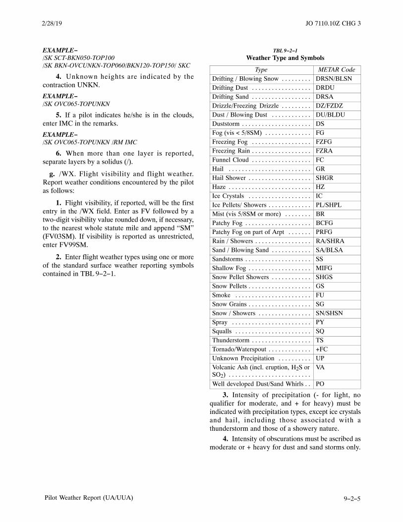
JO 7110.10Z10/12/17
9−2−5Pilot Weather Report (UA/UUA)
EXAMPLE−/SK SCT-BKN050-TOP100/SK BKN-OVCUNKN-TOP060/BKN120-TOP150/ SKC
4. Unknown heights are indicated by thecontraction UNKN.
EXAMPLE−/SK OVC065-TOPUNKN
5. If a pilot indicates he/she is in the clouds,enter IMC in the remarks.
EXAMPLE−/SK OVC065-TOPUNKN /RM IMC
6. When more than one layer is reported,separate layers by a solidus (/).
g. /WX. Flight visibility and flight weather.Report weather conditions encountered by the pilotas follows:
1. Flight visibility, if reported, will be the firstentry in the /WX field. Enter as FV followed by atwo-digit visibility value rounded down, if necessary,to the nearest whole statute mile and append “SM”(FV03SM). If visibility is reported as unrestricted,enter FV99SM.
2. Enter flight weather types using one or moreof the standard surface weather reporting symbolscontained in TBL 9−2−1.
TBL 9−2−1
Weather Type and Symbols
Type METAR CodeDrifting / Blowing Snow . . . . . . . . . DRSN/BLSNDrifting Dust . . . . . . . . . . . . . . . . . . DRDUDrifting Sand . . . . . . . . . . . . . . . . . . DRSADrizzle/Freezing Drizzle . . . . . . . . . DZ/FZDZDust / Blowing Dust . . . . . . . . . . . . DU/BLDUDuststorm . . . . . . . . . . . . . . . . . . . . . DSFog (vis < 5/8SM) . . . . . . . . . . . . . . FGFreezing Fog . . . . . . . . . . . . . . . . . . FZFGFreezing Rain . . . . . . . . . . . . . . . . . . FZRAFunnel Cloud . . . . . . . . . . . . . . . . . . FCHail . . . . . . . . . . . . . . . . . . . . . . . . . GRHail Shower . . . . . . . . . . . . . . . . . . . SHGRHaze . . . . . . . . . . . . . . . . . . . . . . . . . HZIce Crystals . . . . . . . . . . . . . . . . . . . ICIce Pellets/ Showers . . . . . . . . . . . . . PL/SHPLMist (vis 5/8SM or more) . . . . . . . . BRPatchy Fog . . . . . . . . . . . . . . . . . . . . BCFGPatchy Fog on part of Arpt . . . . . . . PRFGRain / Showers . . . . . . . . . . . . . . . . . RA/SHRASand / Blowing Sand . . . . . . . . . . . . SA/BLSASandstorms . . . . . . . . . . . . . . . . . . . . SSShallow Fog . . . . . . . . . . . . . . . . . . . MIFGSnow Pellet Showers . . . . . . . . . . . . SHGSSnow Pellets . . . . . . . . . . . . . . . . . . . GSSmoke . . . . . . . . . . . . . . . . . . . . . . . FUSnow Grains . . . . . . . . . . . . . . . . . . . SGSnow / Showers . . . . . . . . . . . . . . . . SN/SHSNSpray . . . . . . . . . . . . . . . . . . . . . . . . PYSqualls . . . . . . . . . . . . . . . . . . . . . . . SQThunderstorm . . . . . . . . . . . . . . . . . . TSTornado/Waterspout . . . . . . . . . . . . . +FCUnknown Precipitation . . . . . . . . . . UPVolcanic Ash (incl. eruption, H2S orSO2) . . . . . . . . . . . . . . . . . . . . . . . . .
VA
Well developed Dust/Sand Whirls . . PO
3. Intensity of precipitation (- for light, noqualifier for moderate, and + for heavy) must beindicated with precipitation types, except ice crystalsand hail, including those associated with athunderstorm and those of a showery nature.
4. Intensity of obscurations must be ascribed asmoderate or + heavy for dust and sand storms only.
2/28/19 JO 7110.10Z CHG 3

JO 7110.10Z 10/12/17
9−2−6 Pilot Weather Report (UA/UUA)
No intensity for blowing dust, blowing sand, orblowing snow.
EXAMPLE−/WX FV01SM +DS000-TOP083/ SKC /RM DURC
5. When more than one form of precipitation iscombined in the report, the dominant type must bereported first.
EXAMPLE−/WX FV00SM +TSRAGR
6. When FC is entered in /WX, FUNNELCLOUD is spelled out on /RM. When +FC is enteredin /WX, TORNADO or WATERSPOUT is spelledout in the /RM TEI.
EXAMPLE−/WX FC /RM FUNNEL CLOUD/WX +FC /RM TORNADO or WATERSPOUT
7. State the size of the hail in remarks in ¼”increments or any hail less than ¼” is stated as “GRless than ¼”.
8. The proximity qualifier VC (Vicinity) is onlyused with TS, FG, FC, +FC, SH, PO, BLDU, BLSA,and BLSN.
EXAMPLE−/WX FV02SM BLDU000-TOP083 VC W
9. When more than one type of weather isreported enter in the following order: 1) TORNADO,WATERSPOUT, OR FUNNEL CLOUD; 2)Thunderstorm with or without associatedprecipitation; 3) Weather phenomena in order ofdecreasing predominance. No more than three groupsin a single PIREP.
10. Weather layers must be entered with thebase and/or top of the layer when reported. Use thesame format as in the /SK TEI.
EXAMPLE−/WX FU002-TOP030
h. /TA. Air Temperature. Report outside airtemperature using two digits in degrees Celsius.Prefix negative temperatures with a M; for example,/TA 08 or /TA M08.
i. /WV. Wind direction and speed. If reported,wind direction from which the wind is blowing mustbe coded using three figures. Directions less than 100degrees must be preceded by a “0”. For example, awind direction of 90 degrees is coded as 090. Thewind speed must be entered as a two or three digit
group immediately following the wind direction. Thespeed must be coded in whole knots using thehundreds digit (if not zero) and the tens and unitsdigits. The wind group always ends with ”KT” toindicate that winds are reported in knots. Speeds ofless than 10 knots must be coded using a leading zero.For example, a wind speed of 8 knots must be coded08KT and a wind speed of 112 knots must be coded112kt.
EXAMPLE−/WV 28080KT/WV 28008KT/WV 280105KT
j. /TB. Turbulence. Report intensity, type, andaltitude as follows:
1. Intensity. Enter duration if reported by thepilot (INTMT, OCNL, CONS) and intensity usingcontractions LGT, MOD, SEV, or EXTRM. Separatea range or variation of intensity with a hyphen; forexample, MOD-SEV. If turbulence was notencountered, enter NEG.
2. Type. Enter CAT or CHOP if reported by thepilot.
3. Altitude. Report altitude only if it differsfrom value reported in /FL. When a layer ofturbulence is reported, separate height values with ahyphen. If lower or upper limits are not defined, useBLO or ABV.
EXAMPLE−/TB LGT 040/TB MOD-SEV BLO 080/TB MOD-SEV CAT 350/TB NEG 120-180/TB MOD CHOP 220/NEG 230-280/TB MOD CAT ABV 290
k. IC. Icing. Report intensity, type and altitude oficing as follows:
1. Intensity. Enter intensity first usingcontractions TRACE, LGT, MOD, or SEV. Separatereports of a range or variation of intensity with ahyphen. If icing was not encountered, enter NEG.
2. Type. Enter the reported icing type as RIME,CLR, or MX.
3. Altitude. Enter the reported icing/altitudeonly if different from the value reported in the /FLTEI. Use a hyphen to separate reported layers oficing. Use ABV or BLO when a layer is not defined.
3/15/077110.65R CHG 2JO 7110.10Z CHG 3 2/28/19

JO 7110.10Z10/12/17
9−2−7Pilot Weather Report (UA/UUA)
EXAMPLE−/IC LGT-MOD MX 085/IC LGT RIME/IC MOD RIME BLO 095/IC SEV CLR 035-062
4. When icing is reported always reporttemperature in the /TA TEI.
l. /RM. Remarks. Use this TEI to report aphenomenon which is considered important but doesnot fit in any of the other TEIs. This includes, but isnot limited to, low level wind shear (LLWS) reports,thunderstorm lines, coverage and movement, size ofhail (1/4’’ increments), lightning, clouds observedbut not encountered, geographical or localdescription of where the phenomenon occurred,International Standard Atmospheric (ISA) reportsand contrails. Report hazardous weather first.Describe LLWS to the extent possible.
1. Wind Shear. +/- 10 Kts or more fluctuationsin airspeed, within 2,000 Ft of the surface, requires anUUA report. When Low Level Wind Shear is enteredin a pilot report enter LLWS as the first remark in the/RM TEI. LLWS may be reported as -, +, or +/-depending on how it effects the aircraft. If thelocation is different than the /OV or /FL fields,include the location in the remarks.
EXAMPLE−/RM LLWS +/-15 KT SFC-008 DURC RY22 JFK
2. FUNNEL, CLOUD, TORNADO, andWATERSPOUT are entered with the direction ofmovement if reported.
EXAMPLE−/RM TORNADO E MOV E
3. Thunderstorm. Enter coverage (ISOL, FEW,SCT, NMRS) and description (LN,BKN LN,SLDLN) if reported. Follow with ”TS,” the location andmovement, and the type of lightning if reported.
EXAMPLE−/RM NMRS TS S MOV E GR1/2
4. Lightning. Enter frequency (OCNL, FRQ,CONS), followed by type (LTGIC, LTGCC,LTGCG, LTGCA, or combinations), if reported.
EXAMPLE−/RM OCNL LTGICCG
5. Electric Discharge. Enter DISCHARGEfollowed by the altitude.
EXAMPLE−/RM DISCHARGE 120
6. Clouds. Use remarks when clouds can be seenbut were not encountered and reported in /SK.
EXAMPLE−/RM CB E MOV N/RM OVC BLO
7. Plain Language. If specific phraseology is notadequate, use plain language to describe thephenomena or local geographic locations. Includeremarks that do not fit in other TEIs like DURC,DURD, RCA, TOP, TOC, or CONTRAILS.
EXAMPLE−/RM BUMPY VERY ROUGH RIDE/RM CONTRAILS/UA/OV BIS270030/TM 1445/FL060/TP CVLT/TBLGT /RM Donner Summit Pass
8. Volcanic Activity. Volcanic eruption, ashclouds, and/or sulfur gases are Urgent PIREPs.Reports of volcanic activity must include as muchinformation as possible; for example, the name of themountain, ash clouds observed and their movement,the height of the top and bottom of the ash clouds, etc.
(a) If a pilot detected the smell of sulfur gases(H2S or SO2) in the cabin and reported volcanic ashclouds, include “VA” in Weather and “H2S,” “SO2,”or “SULFUR SMELL” in Remarks.
NOTE−The smell of sulfur gases in the cockpit may indicatevolcanic activity that has not yet been detected orreported and/or possible entry into an ash-bearing cloud.H2S, also known as sewer gas, has the odor of rotten eggs.SO2 is identifiable as the sharp, acrid odor of a freshlystruck
EXAMPLE−UUA /OV PANC240075 /TM 2010 /FL370/TP DC10 /WXVA /RM VOLCANIC ERUPTION 2008Z MT AU-GUSTINE ASH 40S MOV SSE SO2
(b) If a pilot only detected the smell of sulfurgases (H2S or SO2) in the cabin and confirmed therewere no volcanic ash clouds, classify the PIREP asRoutine and include “VA” in Weather and “H2S NOASH,” “SO2 NO ASH,” or “SULFUR SMELL NOASH” in Remarks.
EXAMPLE−UA /OV PANC240075 /TM 2010 /FL370/TP DC10 /WXVA /RM SULFUR SMELL NO ASH
(c) If a volcanic activity report is receivedfrom other than a pilot, enter Aircraft “UNKN,”
9/13/18 JO 7110.10Z CHG 2

JO 7110.10Z 10/12/17
9−2−8 Pilot Weather Report (UA/UUA)
Flight Level “UNKN,” and in Remarks“UNOFFICIAL.”
9. The ”SKYSPOTTER” program is a result ofa recommendation from the Safer SkiesFAA/INDUSTRY Joint Safety Analysis andImplementation Teams. The term ”SKYSPOTTER”indicates that a pilot has received specialized trainingin observing and reporting inflight weatherphenomenon, pilot weather reports, or PIREPs.When a PIREP from a pilot identifying themselves asa ”SKYSPOTTER” aircraft is received, theadditional comment ”/AWC” must be added at theend of the remarks section of the PIREP.
EXAMPLE−PIREP Text/RM Text/AWC
10. If ISA is reported.
EXAMPLE−/RM ISA −10C
9−2−15. PIREP ENCODING
PIREPs must be coded to ensure the PIREP is storedand subsequently distributed with the surfaceobservation location nearest the condition beingreported. If more than one METAR location isappropriate, select the location that provides thegreatest distribution and/or prominence, such as amajor hub airport.
3/15/077110.65R CHG 2JO 7110.10Z CHG 2 9/13/18

JO 7110.10Z10/12/17
9−3−1Wind and Temperature Aloft Forecast (FB)
Section 3. Wind and Temperature Aloft Forecast (FB)
9−3−1. GENERALWind and temperature aloft forecasts (FB) arecomputer-prepared and issued by the NationalCenters for Environmental Prediction (NCEP) atSuitland, Maryland. The forecasts are valid 6(FB1/8), 12 (FB2/9), and 24 (FB 3/10) hours after theobservation date/times of 0000Z, 0600Z, 1200Z, and1800Z upon which they are based. See TBL 9-3-1 forwind/temperature aloft forecast schedules.
TBL 9−3−1
Wind/Temperature Aloft Forecast Schedules
Type Base DataTime Valid for For use (period)
FB1/8 0000Z 0600Z 0200−0900Z
FB2/9 0000Z 1200Z 0900−1800Z
FB3/10 0000Z 0000Z 1800−0600Z
FB1/8 0600Z 1200Z 0800−1500Z
FB2/9 0600Z 1800Z 1500−0000Z
FB3/10 0600Z 0600Z 0000−1200Z
FB1/8 1200Z 1800Z 1400−2100Z
FB2/9 1200Z 0000Z 2100−0600Z
FB3/10 1200Z 1200Z 0600−1800Z
FB1/8 1800Z 0000Z 2000−0300Z
FB2/9 1800Z 0600Z 0300−1200Z
FB3/10 1800Z 1800Z 1200−0000Z
9−3−2. LEVELS FORECAST
Dependent upon station elevation, FB1/2/3 windforecasts are issued for the following levels: 3, 6, 9,12, 18, 24, 30, 34, and 39 thousand foot levels. Thefirst level for which a wind forecast is issued is1,500 feet or more above the station elevation.Temperature is forecast for all wind levels that are2,500 feet or more above the station. No temperatureis forecast for the 3,000 foot level. The minus signsare deleted preceding the temperatures at the 30, 34,and 39 thousand foot levels. FB8/9/10 are for the45,000 and 53,000 foot levels. They are not normallydisseminated on Service A, but are available onrequest/reply.
9−3−3. DISTRIBUTION
All FBs are transmitted to the WMSCR by NCEP.Distribution by the WMSCR is accomplished inaccordance with established program requirements..


JO 7110.10Z10/12/17
9−4−1Terminal Aerodrome Forecast (TAF)
Section 4. Terminal Aerodrome Forecast (TAF)
9−4−1. GENERALNWS forecast offices prepare and forward 24- or30-hour TAFs for selected U.S. terminals to theWMSCR for distribution. Similar forecasts for theU.S. Military, Canada, and Mexico are sent toWMSCR from the NCEP and Air Force WeatherAgency (AFWA) for distribution.
9−4−2. TERMINAL AERODROMEFORECAST SCHEDULES
TAFs are prepared four times a day and are issued at2330, 0530, 1130, and 1730 UTC.


JO 7110.10Z10/12/17
9−5−1Aviation Surface Forecast/Aviation Cloud Forecast/Area Forecast (FA)
Section 5. Aviation Surface Forecast/Aviation CloudForecast/Area Forecast (FA)
9−5−1. GENERAL
a. Area forecasts (FA) are available for the Gulf ofMexico, Caribbean, Hawaii, and Alaska through theWMSCR and provide an overview of weatherconditions which could impact aviation operations.FAs are issued by the Aviation Weather Center(AWC) in Kansas City, Missouri, the Alaska AviationWeather Unit (AAWU) in Anchorage, Alaska, andthe Weather Forecast Office (WFO) in Honolulu,Hawaii. The delineation of the areas is specified in theNational Weather Service Instruction 10-811.
Canadian and Mexican FAs are also availablethrough WMSCR.
b. FAs consist of the following elementsaccording to each geographical location inTBL 9−5−1.
c. The Aviation Surface Forecast and AviationCloud Forecast are displayed as nine regional viewsand a CONUS view. These images are produced bythe Aviation Weather Center and distributed byNOAAPORT and static URLs. See FIG 9−5−1,Graphical Forecast Images, for regional views.
TBL 9−5−1
Area Forecasts (FA)
Gulf of Mexico Caribbean Hawaii AlaskaSynopsis X X X
Clouds and Weath-er
X X X
X
(IncludesAIRMETs)
Icing and FreezingLevel
X X X
Turbulence X X X
9−5−2. AREA FORECAST (FA) SCHEDULE
FAs are issued three times a day in Alaska and theGulf of Mexico; and four times a day in Hawaii andthe Caribbean. The issuance times are in TBL 9−5−2.
TBL 9−5−2
Area Forecast (FA) Schedule
Gulf of Mexico(UTC)
Caribbean (UTC) Hawaii (UTC) Alaska
1st Issuance 0130 0330 0430 0415 DT0515 ST
2nd Issuance 1030 0930 0940 1215 DT1315 ST
3rd Issuance 1830 1530 1540 2015 DT2115 ST
4th Issuance 2130 2140
Note: DT – Daylight Time, ST – Standard Time, UTC – Coordinated Universal Time
2/28/19 JO 7110.10Z CHG 3

JO 7110.10Z 10/12/17
9−5−2 Aviation Surface Forecast/Aviation Cloud Forecast/Area Forecast (FA)
9−5−3. AVIATION SURFACE FORECASTAND AVIATION CLOUD FORECASTISSUANCE TIMESThe Aviation Surface Forecast and Aviation CloudForecast are issued 8 times a day and are composed
of 6 snapshots that are valid for up to 18 hours. Theimages are based on forecast model run times of 00Z,03Z, 06Z, 09Z, 12Z, 15Z, 18Z, and 21Z. The actualissuance time will be 1−2 hours after each model run.The delays are due to latency.
FIG 9−5−1
Graphic Forecast Images
3/15/077110.65R CHG 2JO 7110.10Z CHG 3 2/28/19

JO 7110.10Z10/12/17
9−6−1Severe Weather Forecasts
Section 6. Severe Weather Forecasts
9−6−1. GENERAL
Severe weather forecasts are issued by the NWSStorm Prediction Center (SPC) in Norman,Oklahoma, in the form of weather watches,convective outlooks, and status reports and transmit-ted to WMSCR for distribution. An Aviation WatchNotification Message (SPC AWW) is the weatherwatch formatted for the aviation community to alertthem of organized thunderstorms forecast to producetornadic and/or severe weather. FSSs may obtain thepublic weather watch (SPC WW) from WMSCR ifdesired.
9−6−2. DISTRIBUTION
Upon receipt of SPC AWW alert, the WMSCRimmediately transmits the report on selected ServiceA circuits. Severe weather status reports (WW-A) arenever urgent. These are relayed unscheduled.
9−6−3. CONVECTIVE OUTLOOKNARRATIVE (AC)
The Storm Prediction Center will issue ACsnumerous times each day. These forecasts describethe potential for severe and non-severe convectiveactivity across the contiguous U.S.


JO 7110.10Z10/12/17
9−7−1Flight Advisories
Section 7. Flight Advisories(SIGMET/WS−Airmet/WA−Convective SIGMET/WST)
9−7−1. GENERAL
Flight advisories are issued by the AWC in KansasCity, Missouri, the AAWU in Anchorage, Alaska,and the WFO in Honolulu, Hawaii, for the occurrenceor expected occurrence of specified en route weatherphenomena which may affect the safety of aircraftoperations. The report type designator WS forSIGMETs, WST for Convective SIGMETs, and WAfor AIRMETs is used to effect selective distribution
For the contiguous U.S., WSTs are issued hourly at55 minutes past every hour. WAs are issued asdescribed in TBL 9-7-1.
9−7−2. DISTRIBUTION
WSs are distributed at unscheduled times to allService A circuits. WAs and WSTs bulletins aredistributed as scheduled products. Updates oramendments issued will completely replace thepreviously issued advisory.
TBL 9−7−1
(Effective through 09/17/14)
1st ScheduledIssuance (UTC)
2nd ScheduledIssuance (UTC)
3rd ScheduledIssuance (UTC)
4th ScheduledIssuance (UTC)
CONUS 0255 0855 1455 2055Alaska 0145 (DT)/
0245 (ST)0745 (DT)/0845 (ST)
1345 (DT)/1445 (ST)
1945 (DT)/2045 (ST)
Hawaii 0400 1000 1600 2200Note: DT – Daylight Time, ST – Standard Time
TBL 9−7−1
(Effective 09/18/14)
1st ScheduledIssuance (UTC)
2nd ScheduledIssuance (UTC)
3rd ScheduledIssuance (UTC)
4th ScheduledIssuance (UTC)
CONUS 0255 0855 1455 2055Alaska 0415 (DT)/
0515 (ST)1215 (DT)/1315 (ST)
2015 (DT)/2115 (ST)
None
Hawaii 0400 1000 1600 2200Note: DT – Daylight Time, ST – Standard Time


JO 7110.10Z10/12/17
9−8−1Center Weather Advisory (CWA)
Section 8. Center Weather Advisory (CWA)
9−8−1. GENERAL
A Center Weather Advisory (CWA) is an unsched-uled weather advisory for conditions meeting orapproaching national in-flight advisory (WA, WS, orWST) criteria. It is primarily used by aircrews toanticipate and avoid adverse weather conditions inthe en route and terminal environments.
9−8−2. CRITERIA
a. CWAs are valid for up to 2 hours and mayinclude forecasts of conditions expected to beginwithin 2 hours of issuance. If conditions are expectedto persist after the advisory’s valid period, a statementto that effect is included in the last line of the text.Additional CWAs will subsequently be issued asappropriate. The CWSU will issue a CWA:
1. When necessary to supplement an existingWS, WST, or WA for the purpose of refining orupdating the location, movement, extent, or intensityof the weather event relevant to the ARTCC’s area ofresponsibility.
2. When an inflight advisory has not yet beenissued, but the observed or expected weatherconditions meet WS, WST or WA criteria based oncurrent pilot reports and reinforced by other sourcesof information concerning existing meteorologicalconditions.
3. When observed, or developing weatherconditions do not meet WS, WST or WA criteria butcurrent pilot reports or other weather informationsources indicate that an existing, or anticipated,meteorological phenomena will adversely affect the
safe flow of air traffic within the ARTCC’s area ofresponsibility.
b. The CWA will describe the location of thephenomenon using ARTCC relevant points ofreference, such as VORs, and will include the height,extent, intensity, and movement of the phenomenon.Each CWA will have a phenomenon number.
c. The format of the CWA communications headeris: (ARTCC designator)(phenomenon number) CWA(date/time issued in UTC)/(ARTCC designator)CWA (issuance number) VALID UNTIL (date/timein UTC)/(FROM) (affected area)/(text).
EXAMPLE−ZOB1 CWA 032141ZOB CWA 101 VALID UNTIL 032300 FROM 10S DET TO 40N DJB TO 40E SBN TO 80SE MKGLN SEV TSTMS WITH EXTRM PCPN MOVG FROM2525 3/4 INCH HAIL RPRTD LAST 5 MINS 20 SW YIP.TSTMS WITH HVY TO EXTRM PCPN CONTG DTWAREA BYD 2300
ZKC1 CWA 121528ZKC CWA 102 VALID UNTIL 121728STL DIAM 30 NM. NMRS RPTS OF MOD TO SEV ICG080/090.. LGT OR NEG ICG RPTD 040/120 RMNDR OFZKC AREA AND NE OF AREA.
9−8−3. DISTRIBUTION
The CWA will be distributed to ARTCC areasupervisors and traffic management coordinators andwill be entered through FAA AISR and othercommunications media to make it available fordissemination to other FAA and NWS facilities.


JO 7110.10Z10/12/17
10−1−1General
Chapter 10. Airport Lighting and Visibility Aids (Alaska Only)
Section 1. General
10−1−1. AIRPORT LIGHTING
a. General Lighting. Operate airport lighting inaccordance with associated tables except:
1. As requested by the pilot.
2. As required by facility directives or letters ofagreement to meet local conditions or requirements.
3. As specialist deems necessary if not contraryto pilot’s request or local directives.
b. Emergency Lighting. When it appears that anemergency has or will occur, provide for theoperation of all appropriate airport lighting aids inaccordance with local procedures and/or as required.
10−1−2. OBSTRUCTION LIGHTS
If controls are provided, operate the lights betweensunset and sunrise.
10−1−3. ROTATING BEACON
If controls are provided, turn on the rotating beacon:
a. Between sunset and sunrise.
b. Between sunrise and sunset when the reportedceiling or visibility is below basic VFR minima.
10−1−4. APPROACH LIGHTS
Operate approach lights:
a. Between sunset and sunrise when one of thefollowing conditions exists:
1. They serve the landing runway.
2. They serve a runway to which an approach isbeing made but aircraft will land on another runway.
b. Between sunrise and sunset when the ceiling isless than 1,000 feet or the prevailing visibility is5 miles or less and approaches are being made to:
1. A landing runway served by the lights.
2. A runway served by the lights but aircraft arelanding on another runway.
3. The airport, but landing will be made on arunway served by the lights.
c. As requested by the pilot.
d. As you deem necessary, if not contrary to pilot’srequest.
NOTE−In the interest of energy conservation, the approachlighting system should be turned off when not needed foraircraft operations.
10−1−5. APPROACH LIGHTING SYSTEMNTENSITY SETTINGS (ALS)
Operate intensity controls in accordance with thevalues depicted. (See TBL 10−1−1)
TBL 10−1−1
ALS Intensity Setting
StepVisibility (Applicable to runway served by lights)
Day Night
5 Less than 1 mile.*Whenrequested.
4 1 to but not including 3 miles.Whenrequested.
3 3 to but not including 5 miles.Less than 1mile.*
2 5 to but not including 7 miles.1 to 3 milesinclusive.
1 When requested.Greater than3 miles.
* and/or 6,000 feet or less of RVR on the runwayserved by the ALS and RVR.
Note.− Daylight steps 2 and 3 provide recommendedsettings applicable to conditions in ALS IntensitySettings.
10−1−6. SEQUENCED FLASHING LIGHTS(SFL)
Operate sequenced flashing lights when the visibilityis less than 3 miles and instrument approaches arebeing made to the runway served by the associatedALS.

JO 7110.10Z 10/12/17
10−1−2 General
NOTE−SFLs are a component of the ALS and cannot be operatedwhen the ALS is off.
10−1−7. RUNWAY EDGE LIGHTS
Operate the runway edge light system(s) serving therunway(s) in use as follows:
a. Between sunset and sunrise.
1. For departures when an aircraft calls forairport advisory or requests the lights be turned onuntil the aircraft reports departing the airport area or15 minutes after the last contact with the aircraft.
2. For arrivals when an aircraft calls for airportadvisory or when the associated approach controladvises that an aircraft is on approach until the aircraftreports/is observed clear of the runway or 15 minutesafter last radio contact or arrival time.
b. Between sunrise and sunset, turn the lights onwhen the surface visibility is less than 2 miles asdescribed in subparagraphs 10−1−7a1 and a2.
c. The specialist considers it necessary, or it isrequested by a pilot and no other known aircraft willbe adversely affected.
d. Do not turn on the runway edge lights when aNOTAM closing the runway is in effect.
e. Alaska. The runway lights should remain onfrom the end of civil twilight to the beginning of civiltwilight. If the runway lights are operated part-timein this period, broadcast a warning over the airportadvisory frequency 2 minutes before turning thelights off.
10−1−8. CHANGING LIGHTED RUNWAYS
a. To switch lights:
1. Advise all known aircraft that the lights are tobe changed, specifying the runway to be lighted.
2. Turn on the lights for the new runway30�seconds before turning off the other runway lights,equipment permitting.
b. When a pilot requests that other than thefavored runway be lighted and two runways cannotbe lighted simultaneously, comply with the request ifyou have no knowledge of the lighted runway beingin use. Advise all known aircraft.
10−1−9. MEDIUM INTENSITY APPROACHLIGHTING SYSTEM WITH RUNWAYALIGNMENT INDICATOR LIGHTS(MALSR)/OMNIDIRECTIONAL APPROACHLIGHTING SYSTEM (ODALS)
Operate MALSR/ODALS that have separate on-offand intensity setting controls in accordance withTBL 10−1−2 and TBL 10−1−3.
NOTE−Application concerns use for takeoffs/landings/ap-proaches and does not preclude turning lights on for useof unaffected portions of a runway for taxiing aircraft,surface vehicles, maintenance, repair, etc.
TBL 10−1−2
Two−Step MALS/One−Step RAIL
SettingVisibility
Day NightMALS HI−RAILON Less than 3 miles.
Less than 3miles.*
MALS LOW When requested.3 miles ormore.
*At locations providing part−time flight service, theMALSR must be set to low intensity during the hours ofdarkness when the station is unmanned.
TBL 10−1−3
Three−Step MALS/Three−Step RAIL
SettingVisibility
Day Night3 Less than 2 miles. Less than 1 mile.
2 2 to 5 miles inclusive.1 to but notincluding 3 miles.*
1 When requested. 3 miles or more.*At locations providing part−time flight service, the
air−to−ground radio link must be activated during thehours of darkness when the station is unmanned. If thereis no radio air−to−ground control, the MALSR must beset on intensity step #2 during the hours of darknesswhen the station is unmanned. (Reference− FAA OrderJO 7210.3, Para 10−6−4, Approach Light Systems.)
10−1−10. HIGH INTENSITY RUNWAYLIGHTS (HIRL) ASSOCIATED WITH MALSR
Operate HIRL that controls the associated MALSR inaccordance with the intensity setting in TBL 10−1−4
TBL 10−1−4
HIRL Associated with MALSR
StepVisibility
Day Night5 Less than 1 mile. When requested.
4 1 to but not including2 miles.
Less than 1 mile.
3/15/077110.65R CHG 2JO 7110.10Z CHG 1 3/29/18

JO 7110.10Z10/12/17
10−1−3General
3 2 to but not including3 miles.
1 to but notincluding 3 miles.
2 When requested. 3 to 5 milesinclusive.
1 When requested. More than 5 miles.
NOTE−When switching from a given brightness step setting to alower setting, rotation of the brightness control to a pointbelow the intended step setting and then back to theappropriate step setting will ensure that the MALSR willoperate at the appropriate brightness.
10−1−11. MEDIUM INTENSITY RUNWAYLIGHTS (MIRL)
Operate MIRL or MIRL which control the associatedMALSR in accordance with the TBL 10−1−5.
TBL 10−1−5
MIRL Intensity Setting
StepVisibility
Day Night3 Less than 2 miles. Less than 1 mile.2 2 to 3 miles. 1 to 3 miles.
1 When requested. More than 3miles.
REFERENCE−FAA Order JO 7110.10, para 10−1−11 Note.
10−1−12. HIGH INTENSITY RUNWAY,RUNWAY CENTERLINE (RCLS), ANDTOUCHDOWN ZONE LIGHTS (TDZL)
Operate high intensity runway and associated runwaycenterline and touch-down zone lights in accordancewith TBL 10−1−6.
TBL 10−1−6
HIRL, RCLS, TDZL Intensity Setting
StepVisibility
Day Night5 Less than 1 mile.* When requested.
4 1 to but not including2 miles. Less than 1 mile.
3 2 to but not including3 miles.
1 to but notincluding 3 miles.
2 When requested.3 to 5 milesinclusive.
1 When requested. More than 5 miles.* and/or appropriate RVR/RVV equivalent.
10−1−13. HIRL CHANGES AFFECTING RVR
Keep the appropriate approach controller or PrecisionApproach Radar (PAR) controller informed, inadvance if possible, of HIRL changes that affectRVR.
10−1−14. HIGH SPEED TURNOFF LIGHTS
Operate high speed turnoff lights whenever theassociated runway lights are used for arriving aircraft.Leave them on until the aircraft has either entered ataxiway or passed the last light.
10−1−15. RUNWAY END IDENTIFIERLIGHTS (REIL)
When separate on-off controls are provided, operaterunway end identifier lights when the associatedrunway lights are lighted. Turn the REIL off after:
a. An arriving aircraft has landed.
b. A departing aircraft has left the traffic patternarea.
c. It is determined that the lights are of no furtheruse to the pilot.
d. Operate intensity setting in accordance with thevalues in TBL 10−1−7 except as prescribed insubparas b and c above.
TBL 10−1−7
REIL Intensity Setting, Two−Step System
StepVisibility
Day Night3 Less than 2 miles. Less than 1 mile.
2 2 to 5 miles. 1 to but notincluding 3 miles.
1 When requested. 3 miles or more
10−1−16. TAXIWAY LIGHTS
Operate taxiway lights serving the taxiways, orportions thereof, in use between sunset and sunrisebefore an aircraft taxies onto the taxiway (normallyat the time taxi information is issued) and until ittaxies off it. Operate taxiway lights in accordancewith TBL 10−1−8, TBL 10−1−9, or TBL 10−1−10
3/29/18 JO 7110.10Z CHG 1

JO 7110.10Z 10/12/17
10−1−4 General
TBL 10−1−8
Three Step Taxiway Lights
StepVisibility
Day Night3 Less than 1 mile. When requested.2 When requested. Less than 1 mile.1 When requested. 1 mile or more
TBL 10−1−9
Five Step Taxiway Lights
StepVisibility
Day Night5 Less than 1 mile. When requested.4 When requested. Less than 1 mile.3 When requested. 1 mile or more.
1 & 2 When requested. When requested.
TBL 10−1−10
One Step Taxiway Lights
Day Night
Less than 1 mile. On
10−1−17. VISUAL APPROACH SLOPEINDICATORS (VASIs)
The VASI system with remote on-off switching mustbe operated when it serves the runway in use andwhere intensities are controlled in accordance withTBL 10−1−11 and TBL 10−1−12.
TBL 10−1−11
VASI Intensity Setting, Two−Step System
Step Period ConditionHigh Day Sunrise to
sunset
Low Night Sunrise to sunset
TBL 10−1−12
VASI Intensity Setting, Three−Step System
Step Period ConditionHigh Day Sunrise to sunset
Medium Twilight From sunset to 30 minutesafter sunset andfrom 30 minutes before sunriseto sunrise,*and during twilight in Alaska.
Low Night Sunset to sunrise.
NOTE−1. During a 1-year period, twilight may vary 26 to43 minutes between 25 and 49 degrees N latitude.
2. The basic FAA standard for VASI systems permitsindependent operation by means of photoelectric device.This system has no on-off control feature and is intendedfor continuous operation. Other VASI systems in useinclude those that are operated remotely from the controltower. These systems may consist of either a photoelectricintensity control with only an on-off switch, a two-stepintensity system, or a three-step intensity system.REFERENCE−FAA Order JO 7210.3, Para 10-6-5, Visual Approach Slope Indicator(VASI) Systems.
10−1−18. VISIBILITY AIDS - GENERAL
a. Where RVR/ RVV equipment is operational,irrespective of subsequent operation or nonoperationof navigational or visual aids for the application ofRVR/RVV as a takeoff or landing minima, furnish thevalues for the runway in use in accordance withParagraph 10−1−19, RVR/RVV.
b. Issue current touchdown RVR/RVV for therunway(s) in use:
1. When prevailing visibility is 1 mile or lessregardless of the value indicated.
2. When RVR/RVV indicates a reportable valueregardless of the prevailing visibility.
NOTE−Reportable values are: RVR 6,000 feet or less; RVV1-1/2 miles or less.
3. When it is determined from a reliable sourcethat the indicated RVR value differs by more than400 feet from the actual conditions within the area ofthe transmissometer, the RVR data is not acceptableand must not be reported.
NOTE−A reliable source is considered to be a certified weatherobserver, air traffic controller, or pilot.
4. When the observer has reliable reports, or hasotherwise determined that the instrument values arenot representative of the associated runway, the datamust not be used.
10−1−19. RVR/RVV
a. Provide RVR/RVV information by stating therunway, the abbreviation RVR/RVV, and theindicated value. When issued along with otherweather elements, transmit these values in the normalsequence used for weather reporting.
3/15/077110.65R CHG 2JO 7110.10Z CHG 1 3/29/18

JO 7110.10Z10/12/17
10−1−5General
b. When two or more RVR systems serve therunway in use, report the indicated values for thedifferent systems in terms of touchdown, mid, androllout as appropriate.
c. When there is a requirement to issue anRVR/RVV value and a visibility condition greater orless than the reportable values of the equipment isindicated, state the condition as “MORE THAN” or“LESS THAN” the appropriate minimum ormaximum readable value.
d. When a readout indicates a rapidly varyingvisibility condition (1,000 feet or more for RVR; oneor more reportable values for RVV), report the currentvalue followed by the range of visibility variance.
10−1−20. OPERATION OF LANDINGDIRECTION INDICATOR
Align the landing direction indicator with the favoredor designated runway.
3/29/18 JO 7110.10Z CHG 1


JO 7110.10Z10/12/17
11−1−1General
Chapter 11. Interphone Communications
Section 1. General
11−1−1. PURPOSE
a. The procedures and phraseologies contained inthis chapter apply to inter-facility and intra-facilitytelephone communications conducted from anyposition of operation.
b. Interphone use is restricted to authorizedofficial business only.
c. Monitor interphones continuously. At facilitieswithout ringers, keep speaker volume at a levelsufficient to hear all transmissions. In the event ofinterphone failure, use authorized back-upprocedures; for example, commercial telephone,aircraft radio relay.
d. Use the words or phrases in interphonecommunications as contained in the Pilot/ControllerGlossary.
11−1−2. INTERPHONE TRANSMISSIONPRIORITIES
Give priority to interphone transmissions as follows:
a. First priority. Emergency messages includingessential information on aircraft accidents orsuspected accidents. After actual emergency haspassed, give a lower priority to messages relating toan accident.
b. Second priority. Clearance and controlinstructions.
c. Third priority. Movement and control messagesusing the following order of precedence whenpossible:
1. Progress reports.
2. Departure or arrival reports.
3. Flight plans.
d. Fourth priority. Movement messages on VFRaircraft.
e. Fifth priority. NOTAM coordination.
f. Sixth priority. Administrative messages; forexample, outages.
11−1−3. PRIORITY INTERRUPTION
Use the words “emergency” or “control” forinterrupting lower priority messages when you havean emergency or control message to transmit.
11−1−4. MESSAGE INITIATION
Initiate interphone messages as follows:
a. Assure line is not in use.PHRASEOLOGY−LINE CLEAR?
b. If line is not in use, establish contact with thedesired facility and/or position.EXAMPLE−EXAMPLE-Manual signaling (Ring Line):FSS-(Calls Center via DA/IA Line).Center- “Anchorage Center” or “Sector D-5.”FSS- “Kenai radio. Kenai progress Apache One TwoThree.”Center- “Go ahead”FSS- “Over Kenai...etc.” “L-H”Center- “C-M”
Voice signaling (Shout Line):FSS- “Fort Worth Center, Fort Worth Radio, ClearanceRequest.“Center “Fort Worth Center, Go Ahead.”FSS- “Request Clearance, Army ......etc.”
c. When calling or replying on an interphone linewhich connects only two facilities, you may omit thefacility’s name.EXAMPLE−“Radio, inbound estimate.”
d. FSS.
1. Inflight position. State the name of theFSS/sector followed by the word “RADIO” andposition, if appropriate.EXAMPLE−“Fairbanks Radio.”“Leesburg Radio”
11−1−5. MESSAGE TERMINATION
Terminate interphone messages with your operatinginitials.

JO 7110.10Z 10/12/17
11−1−2 General
EXAMPLE−“V-N”

JO 7110.10Z10/12/17
12−1−1General
Chapter 12. Phraseology
Section 1. General
12−1−1. PURPOSE
This chapter prescribes standardized procedures andphraseologies to be used by specialist whencommunicating weather and aeronauticalinformation in broadcast, radiotelephone, andinterphone communications. Where position orprocedure−specific phraseology is required,reference is to be made to the relevant chapter of thisorder.
12−1−2. PHRASEOLOGY
The annotation PHRASEOLOGY denotes theprescribed words and/or phrases to be used incommunications.
NOTE−Specialists may, after first using the prescribedphraseology for a specific procedure, rephrase themessage to ensure the content is understood. Goodjudgment must be exercised when using nonstandardphraseology.
12−1−3. WORDS AND PHRASES
Use the words or phrases in broadcast,radiotelephone, and interphone communications ascontained in the Pilot/Controller Glossary.
12−1−4. ANNOUNCING MISSING ITEMS
With the exception of RVR, announce the word“missing” when any item or component of a weatherreport is not reported, or in place of unreadable orobviously incorrect items or portions of weatherreports. When appropriate, instead of speaking thename of several locations with missing reports,announce: “Other scheduled reports missing.”
NOTE−On occasion, a parameter from an automated observationmay be reported as missing in the body of the report butis available as a manually reported parameter in theremarks section. When the report is spoken, include themanually reported element in its proper sequence withinthe report.
12−1−5. ICAO PHONETICS
Use the ICAO pronunciation of numbers and, asnecessary, individual letters for clarity. The ICAOradiotelephony alphabet and pronunciation guide arecontained in TBL 12−1−1.
TBL 12−1−1
ICAO Phonetics
Character Word Pronunciation
0 Zero ZE−RO1 One WUN2 Two TOO3 Three TREE4 Four FOW−ER5 Five FIFE6 Six SIX7 Seven SEV−EN8 Eight AIT9 Nine NIN−ER
A Alfa ALFAHB Bravo BRAHVOHC Charlie CHARLEED Delta DELLTAHE Echo ECKOHF Foxtrot FOKSTROTG Golf GOLFH Hotel HOHTELLI India INDEEAHJ Juliett JEWLEEETTK Kilo KEYLOHL Lima LEEMAHM Mike MIKEN November NOVEMBERO Oscar OSSCARP Papa PAHPAHQ Quebec KEHBECKR Romeo ROWMEOHS Sierra SEEAIRAHT Tango TANGGOU Uniform YOUNEEFORMV Victor VIKTAHW Whiskey WISSKEY

JO 7110.10Z 10/12/17
12−1−2 General
X X−ray ECKSRAYY Yankee YANGKEYZ Zulu ZOOLOO
NOTE−Syllables to be emphasized in pronunciation are in boldface.
12−1−6. RELAY OF ATCCOMMUNICATIONS
Prefix a clearance, information, or a request forinformation which will be relayed from a controlfacility to an aircraft with the appropriate phrase“A−T−C clears,” “A−T−C advises,” or “A−T−Crequests.”
12−1−7. EXPEDITIOUS COMPLIANCE
a. Use the word “immediately” only whenexpeditious compliance is required to avoid animminent situation.
b. Use the word “expedite” only when promptcompliance is required to avoid the development ofan imminent situation.
c. In either case, and if time permits, include thereason for this action.
12−1−8. WEATHER PHRASEOLOGY
Use the following phraseology and procedures forstating surface weather observations and forinformation similarly encoded in other aviationweather products and forecasts.
a. Location.
1. Announce the geographic name (not theidentifier) once.
EXAMPLE−“Paducah.”
2. When the location name is duplicated within500 miles, follow the location name with the statename.
EXAMPLE−“Columbus, Ohio.”
3. When weather reports originate at more thanone airport at the same geographical location,identify the airport.
EXAMPLE−“Anchorage, Merrill.”“Chicago, O’Hare.”
4. Where it is considered necessary and isrequested by the military base commander, broadcastmilitary observations by stating the location, thename of the airport if different, and the controllingmilitary branch.
EXAMPLE−“Joint Base Andrews.”“Elmendorf, Air Force Base.”“Fort Riley, Marshall Army Air Field.”“Norfolk Naval Air Station.”
b. If “AUTO” appears after the date/time elementand is presented as a singular report, follow thelocation with the word “AUTOMATED.”
PHRASEOLOGY−(Location) AUTOMATED.
c. If a special report is the most recent observationavailable, follow the location with the words“SPECIAL WEATHER REPORT,” (last two digitsof the time) “OBSERVATION.” Use data from therecord report to fill in the items not included in thespecial observation, such as temperature and dewpoint.
d. If the weather data is not available, state thelocation and the word “missing.”
e. Wind Direction and Speed. Announce surfacewind direction and speed by stating the word “wind”followed by the separate digits of the wind directionto the nearest 10 degrees and the separate digits of thespeed. A “G” between two wind speed values isannounced as “gusts.” State local wind as it appearsin the report. Announce the variability of wind at theend of the wind group. (See TBL 12−1−2.)

JO 7110.10Z10/12/17
12−1−3General
TBL 12−1−2
Wind Direction and Speed
Wind Phraseology
00000KT WIND CALM.
26012KT WIND TWO SIX ZERO AT ONETWO.
29012KT260V320
WIND TWO NINER ZERO ATONE TWO WIND VARIABLEBETWEEN TWO SIX ZERO ANDTHREE TWO ZERO.
30008KT WIND THREE ZERO ZERO ATEIGHT.
36012G20KT WIND THREE SIX ZERO AT ONETWO GUSTS TWO ZERO.
VRB04KT WIND VARIABLE AT FOUR.
f. Visibility.
State the word “visibility” followed by the visibilityvalues in miles and/or fractions of miles, exceptannounce values indicated by the figure 0 as “zero.”Announce the separate digits of whole numbers asapplicable. (See TBL 12−1−3.)
TBL 12−1−3
Visibility
Contraction Phraseology0SM Visibility zero.
1/16SM Visibility one sixteenth.1/8SM Visibility one eighth.
M1/4SM Visibility less than one quarter.3/4SM Visibility three quarters.11/2SM Visibility one and one−half.
8SM Visibility eight.25SM Visibility two five.
NOTE−When visibility is less than 3 miles and variable, thisinformation is reported in the remarks.
g. RVR/RVV.
1. Provide RVR/RVV information by statingthe runway, the abbreviation RVR/RVV, and theindicated value. The abbreviations “R-V-R” or“R-V-V” may be spoken in lieu of “visual range” or“visibility value.” When the indicated values areseparated by a V, preface the values with the words“variable,” followed by the first value, the word “to,”then the second value. (See TBL 12−1−4.)
TBL 12−1−4
RVR/RVV
RVR/RVV PhraseologyR36VV11/2 “Runway three six, R−V−V one
and one−half.”R05LVV1V2 “Runway five left, R−V−V
variable between one and two.”R18/2000V3000FT “Runway one eight, R−V−R
variable between two thousandto three thousand. Or Runwayone eight visual range variablebetween two thousand and threethousand.”
R26R/2400FT “Runway two six right visualrange two thousand fourhundred.”
2. When there is a requirement to issue an RVRor RVV value and a visibility condition greater or lessthan the reportable values of the equipment isindicated, state the condition as “MORE THAN” or“LESS THAN” the appropriate minimum ormaximum readable value. (See TBL 12−1−5.)
TBL 12−1−5
RVR/RVV
RVR/RVV PhraseologyR16/M0600FT ‘‘Runway one six runway
visual range less than sixhundred. Or Runway one sixR−V−R less than sixhundred.’’
R36L/M0600V2500FT ‘‘Runway three six left,R−V−R variable betweenless than six hundred andtwo thousand five hundred.Or Runway three six leftvisual range variablebetween less than sixhundred and two thousandfive hundred.’’
R36/P6000FT ‘‘Runway three six R−V−Rmore than six thousand. OrRunway three six visualrange more than sixthousand.’’
h. Weather Elements. TBL 12−1−6 depictssample phraseology for weather element contrac-tions. Intensity refers to precipitation, notdescriptors. Proximity is spoken after the phenomen-on to which it refers. Descriptors are spoken ahead ofweather phenomenon with the exception of‘‘showers’’ which is spoken after the precipitation.

JO 7110.10Z 10/12/17
12−1−4 General
TBL 12−1−7 contains a complete list of weatherelements and appropriate phraseology.
TBL 12−1−6
Examples of Combining Intensity, Descriptors andWeather Phenomenon.
Contractions PhraseologyBLSN BLOWING SNOW
−FZRAPL LIGHT FREEZING RAIN, ICEPELLETS
FZRA FREEZING RAINFZDZ FREEZING DRIZZLEMIFG SHALLOW FOG−SHRA LIGHT RAIN SHOWERSSHRA RAIN SHOWERSSHSN SNOW SHOWERSTSRA THUNDERSTORM, RAIN
+TSRA THUNDERSTORM, HEAVY RAIN(SHOWERS)1
+TSRAGR THUNDERSTORM, HEAVYRAIN, HAIL
VCSH SHOWERS IN THE VICINITY1Since thunderstorms imply showery precipitation,‘‘showers’’ may be used to describe precipitation thataccompany thunderstorms.
TBL 12−1−7
Weather Elements
INTENSITYor
PROXIMITY1
DESCRIPTOR
2
PRECIPITATION
3
OBSCURATION
4
OTHER
5
− Light MI Shallow DZ Drizzle BR Mist PO Well−DevelopedDust/SandWhirls
BC Patchy RA Rain FG Fog SQ Squalls
Moderate(No Qualifier)
DR Low Drifting SN Snow FU Smoke FC+FC
Funnel Cloud,Tornado orWaterspout
BL Blowing SG Snow Grains DU Dust SS Sandstorm
+ Heavy SH Showers IC Ice Crystals SA Sand DS Duststorm
TS Thunderstorm PL Ice Pellets HZ Haze
VC In the Vicinity FZ Freezing GR Hail PY Spray
PR Partial GS Snow Pellets VA Volcanic Ash
UP *UnknownPrecipitation
* Automated stations only.
i. Ceiling and Sky Coverage. 1. State sky coverage in the same order asreported on the weather observation. Announceceiling as follows: (See TBL 12−1−8.)
3/15/077110.65R CHG 2JO 7110.10Z CHG 2 9/13/18

JO 7110.10Z10/12/17
12−1−5General
TBL 12−1−8
Ceiling and Sky Coverage
Designator PhraseologyBKN0001 SKY PARTIALLY OBSCUREDBKN0002 CEILING LESS THAN FIVE
ZERO BROKENFEW0001 SKY PARTIALLY OBSCUREDFEW0002 FEW CLOUDS AT LESS THAN
FIVE ZERO(lowest layer aloft)
BKN/OVC(precede with) CEILING
SCT0001 SKY PARTIALLY OBSCUREDSCT0002 LESS THAN FIVE ZERO
SCATTEREDVV INDEFINITE CEILING
1 Surface−based obscurations. Requires remarks,i.e. RMK FG SCT000, FU BKN000, etc.
2 No remark means the layer is aloft.
2. State cloud heights in tens, hundreds and/orthousands of feet. (See TBL 12−1−9.)
TBL 12−1−9
Cloud Heights
Number Phraseology0001 ZERO003 THREE HUNDRED018 ONE THOUSAND EIGHT
HUNDRED200 TWO ZERO THOUSAND
1 Spoken as zero only when used with VV.
NOTE−1. When the ceiling is less than 3,000 feet and variable,the variable limits will be reported in the remarks.
2. When communicating weather information on theTIBS broadcast or telephone, specialist may announcecloud heights in either group form or in hundreds orthousands of feet, such as seventeen thousand or oneseven thousand.
3. “Group form” is the pronunciation of a series ofnumbers as the whole number, or pairs of numbers theyrepresent rather than pronouncing each separate digit.The use of group form may, however, be negated byfour-digit identifiers or the placement of zeros in theidentifier.
3. Announce sky conditions as indicated below.(See TBL 12−1−10.)
TBL 12−1−10
Sky Conditions
Contraction PhraseologyBKN (height) BROKENCLR1 CLEAR BELOW ONE TWO
THOUSANDFEW FEW CLOUDS AT (height)OVC (height) OVERCASTSCT (height) SCATTEREDSKC CLEAR
1 Automated weather reports.
4. TBL 12−1−11 contains examples of broad-cast phraseology of sky and ceiling conditions.
TBL 12−1−11
Sky and Ceiling Conditions
Condition PhraseologyBKN000BKN010
BKN050 RMKFG BKN000
SKY PARTIALLY OBSCURED,CEILING ONE THOUSANDBROKEN, FIVE THOUSANDBROKEN. FOG OBSCURINGFIVE TO SEVEN EIGHTS OF THESKY.
BKN010 CEILING ONE THOUSANDBROKEN.
SCT000SCT020
OVC035 RMKFG SCT000
SKY PARTIALLY OBSCURED,TWO THOUSAND SCATTERED,CEILING THREE THOUSANDFIVE HUNDRED OVERCAST.FOG OBSCURING THREE TOFOUR EIGHTS OF THE SKY.
SCT020OVC250
TWO THOUSAND SCATTERED,CEILING TWO FIVE THOUSANDOVERCAST.
VV000 INDEFINITE CEILING ZERO.VV012 INDEFINITE CEILING ONE
THOUSAND TWO HUNDRED.
j. Announce surface temperature and dew point bystating the words “temperature” or “dew point,” asappropriate, followed by the temperature in degreesCelsius. Temperatures below zero are announced byprefixing the word “minus” before the values. (SeeTBL 12−1−12.)
TBL 12−1−12
Temperature/Dewpoint
Reading Phraseology
02/M01 ‘‘Temperature two, dew point minusone.’’
04/02 ‘‘Temperature four, dew point two.’’
18/13 ‘‘Temperature one eight, dew point onethree.’’

JO 7110.10Z 10/12/17
12−1−6 General
k. Altimeter Setting.
1. State the word “altimeter” followed by thefour digits of the altimeter setting. (See TBL12-1-13.)
TBL 12−1−13
Altimeter Setting
Altimeter Setting PhraseologyA2989 ‘‘Altimeter two niner eight niner.’’A3001 ‘‘Altimeter three zero zero one.’’A3025 ‘‘Altimeter three zero two five.’’
2. Identify the source of all altimeter settingswhen issued, if not given as part of an identifiedsurface observation. Provide the time of the report ifmore than one hour old.
PHRASEOLOGY−(airport name) (time of report if more than one hour old)ALTIMETER (setting).
3. If a request for the altimeter setting in MBs isreceived, announce the separate digits of the MBequivalent value, using the MB conversion chart,followed by the word “Mbs.” If the MB setting is nota whole number, always round down. (SeeTBL 13-1-14.)
REFERENCE−FAAO JO 7110.10, Para 4-3-5f, Routine Radio Contacts
TBL 12−1−14
Millibar Conversion
Millibar Conver-sion
Phraseology
956.3 ‘‘Altimeter niner five sixmillibars.’’
1002.0 ‘‘Altimeter one zero zero twomillibars.’’
1058.9 ‘‘Altimeter one zero five eightmillibars.’’
4. When altimeter is in excess of 31.00:
(a) Advise all aircraft.
PHRASEOLOGY−ALTIMETER GREATER THAN THREE ONE ZEROZERO. HIGH PRESSURE ALTIMETER PROCEDURESARE IN EFFECT.
(b) Advise VFR aircraft to set altimeter to31.00 en route.
PHRASEOLOGY−RECOMMEND YOU SET ALTIMETER THREE ONEZERO ZERO EN ROUTE.
12−1−9. WEATHER REMARKS
Announce pertinent remarks from surface weatherobservations in accordance with FAA Order JO7340.2, Contractions, and as shown in the followingtables. Do not state additive data or other informationintended for NWS analysis or processing that doesnot contribute to the description of the conditionsoccurring at the station.
a. Sky and Ceiling (See TBL 12−1−15.)
TBL 12−1−15
Sky and Ceiling
Contraction PhraseologyCIG 005V010 ‘‘Ceiling variable
between five hundred andone thousand.’’
CIG 020 RY11 ‘‘Ceiling two thousand atrunway one one.’’
CB N MOV E ‘‘Cumulonimbus northmoving east.’’
CBMAM DSNT S ‘‘Cumulonimbusmammatus distant south.’’
CLDS TPG MT SW ‘‘Clouds toppingmountain southwest.’’
CONTRAILS N FL420 ‘‘Condensation trailsnorth at flight level fourtwo zero.’’
FRQ LTCIC VC ‘‘Frequent lightning incloud in the vicinity.’’
LWR CLDS NE ‘‘Lower cloudsnortheast.’’
OCNL LTGICCG NW ‘‘Occasional lightning incloud and cloud to groundnorthwest.’’
RDGS OBSCD W−N ‘‘Ridges obscured westthrough north.’’
b. Obscuring Phenomena. (See TBL 12−1−16.)
TBL 12−1−16
Obscuring Phenomena
Contraction PhraseologyBLSN SCT000 ‘‘Blowing snow obscuring three
to four−eights of the sky.’’DU BKN000 ‘‘Dust obscuring five to
seven−eights of the sky.’’FG FU FEW000 ‘‘Fog and smoke obscuring one to
two−eights of the sky.’’FU SCT020 ‘‘Smoke layer two thousand
scattered.’’SN BKN000 ‘‘Snow obscuring five to
seven−eights of the sky.’’

JO 7110.10Z10/12/17
12−1−7General
c. Visibility. (See TBL 12−1−17.)
TBL 12−1−17
Visibility
Contraction Phraseology
SFC VIS 1/2 ‘‘Surface visibilityone−half.’’
SFC VIS 15 TWRINC ‘‘Surface visibility one five,tower in clouds.’’
TWR VIS 3/4 ‘‘Tower visibilitythree−quarters.’’
VIS S 1 W 1/4 ‘‘Visibility south one, westone−quarter.’’
VIS 1V3 ‘‘Visibility variable betweenone and three.’’
d. Weather and obstruction to visibility.(See TBL 12−1−18.)
TBL 12−1−18
Weather and Obstruction
Contraction Phraseology
BCFG S ‘‘Patchy fog south.’’
DUST DEVILS NW ‘‘Dust devils northwest.’’
FG DSIPTG ‘‘Fog dissipating.’’
FU DRFTG OVRFLD
‘‘Smoke drifting over field.’’
FUOCTY ‘‘Smoke over city.’’
GR 2 ‘‘Hailstones two inches indiameter.’’
INTMT −RA ‘‘Intermittent light rain.’’
OCNL LTG DSNTNW
‘‘Occasional lightning distantnorthwest.’’
OCNL SHRA ‘‘Occasional moderate rainshowers.’’
−RA OCNLY +RA ‘‘Light rain occasionallyheavy.’’
RAB30 ‘‘Rain began at three zero.’’
SNB15E40 ‘‘Snow began at one five,ended at four zero.’’
SNINCR 5/10 ‘‘Snow increase five inchesduring past hour, ten inches onthe ground.’’
TS OHD MOV E ‘‘Thunderstorm overhead,moving east.’’
FRQ LTGCG TS WMOV E
‘‘Frequent lightning cloud toground, thunderstorm westmoving east.’’
UNCONFIRMEDTORNADO 15W
OKC MOV NE 2015
‘‘Unconfirmed tornado onefive west of Oklahoma City,moving northeast sighted attwo zero one five zulu.’’
WET SN ‘‘Wet snow.’’
e. Wind. (See TBL 12−1−19.)TBL 12−1−19
Wind
Contraction Phraseology
PK WND 33048/22 ‘‘Peak wind three threezero at four eight occurredat two two past the hour.’’
WSHFT 30 ‘‘Wind shifted at threezero.’’

JO 7110.10Z 10/12/17
12−1−8 General
f. Pressure. (See TBL 12−1−20.)
TBL 12−1−20
Pressure
Contraction Phraseology
PRESFR ‘‘Pressure falling rapidly.’’
PRESRR ‘‘Pressure rising rapidly.’’
g. Freezing Level Data. (See TBL 12−1−21.)
TBL 12−1−21
Freezing Level Data
Contraction Explanation
RADAT 87045 Relative humidity 87percent, only crossing ofzero degrees Celsiusisotherm was four thousandfive hundred M−S−L.
RADAT 87L024105 Relative humidity 87percent at the lowestcrossing of zero degreesCelsius. Two crossingsoccurred at two thousandfour hundred and one zerothousand five hundredM−S−L.
RADAT MISG The sounding terminatedbelow the first crossing ofthe zero degree Celsiusisotherm. Temperatureswere all above freezing.
RADAT ZERO The entire sounding wasbelow zero degrees Celsius.
h. Icing Data. (See TBL 12−1−22.)
TBL 12−1−22
Icing Data
Contraction Explanation
RAICG 12 MSL Icing at one thousand twohundred M−S−L.
RAICG 24 MSL SNW Icing at two thousand fourhundred M−S−L in snow.
i. Maintenance Data. (See TBL 12−1−23.)
TBL 12−1−23
Maintenance Data
RVR/RVV PhraseologyPNO ‘‘Precipitation amount not
available.’’RVRNO ‘‘R−V−R (or runway visual
range) information notavailable.’’
TSNO ‘‘Thunderstorm/lightninginformation not available.’’
VISNO ‘‘Visibility sensorinformation not available.’’
12−1−10. WEATHER ADVISORIES
a. When announcing weather advisories, includethe complete advisory description including theproduct name and alphanumeric identification.Specify Eastern, Central, or Western section asapplicable when stating WSTs.
PHRASEOLOGY−AIRMETALERT WEATHER WATCH, ONE ZERO SEVEN FORSEVERE THUNDERSTORMSCONVECTIVE SIGMET TWO SEVEN EASTERNHOUSTON CENTER WEATHER ADVISORY ONE,ISSUANCE TWOSIGMET WHISKEY THREE
b. Do not read the OUTLOOK section of WSTswhen stating the advisory. Data contained in theOUTLOOK concerning convective activity location,movement, and intensity may be extracted forcompilation in forecast summarizations.
EXAMPLE−‘‘Convective SIGMET one seven Eastern−from five zerosouth of St. Petersburg to three zero south of Columbus,line of thunderstorms three five miles wide moving east atone five knots. Maximum tops four seven thousand.’’
c. VNR. When VFR flight is proposed and skyconditions or visibilities are present or forecast,surface based or aloft that, in your judgment, wouldmake visual flight doubtful, include one of thefollowing statements:
PHRASEOLOGY−V−F−R FLIGHT NOT RECOMMENDED (location ifapplicable) DUE TO (conditions).orV−F−R NOT RECOMMENDED.

JO 7110.10Z10/12/17
12−1−9General
12−1−11. RADAR
Use the following phraseology and procedures forcommunicating radar products: Radar displays. When stating precipitation intensityfrom a radar display (such as NEXRAD), use thefollowing four categories as appropriate:
a. Light: (Equates to radar return levels of lessthan 30 dBZ.)
b. Moderate: (Equates to radar return levels of 30to 40 dBZ.)
c. Heavy: (Equates to radar return levels of greaterthan 40 to 50 dBZ.)
d. Extreme: (Equates to radar return levels ofgreater than 50 dBZ.)
12−1−12. WINDS AND TEMPERATURESALOFT FORECAST (FB)
When announcing the FB, use the followingphraseology and procedures:
a. State the altitude, then announce wind directionand speed by the separate digits of the wind directionto the 10-degree multiple, the word AT, and theseparate digits of the speed.
b. When the forecast speed is less than 5 knots, thecoded group is 9900 and read, “light and variable.”
c. Encoded wind speed 100 to 199 knots have 50added to the direction code and 100 subtracted fromthe speed.
d. If wind speed is forecast at 200 knots or greater,the wind group is coded as 199 knots; for example,7799 is decoded 270 degrees at 199 knots or greater.
e. A six-digit group includes forecast temperature.Provide temperatures on request only, stating theword ”temperature,” followed by the word “minus,”as appropriate, and the separate digits. (SeeTBL 12-1-24.)
TBL 12−1−24
Altitude
Coded Phraseology2707 ‘‘(altitude), two seven zero at seven.’’7799 ‘‘(altitude), two seven zero at one niner
niner or greater.’’850552 ‘‘(altitude), three five zero at one zero
five, temperature minus five two.’’9900+00 ‘‘(altitude), light and variable,
temperature zero.’’
12−1−13. NUMBER USAGE
State numbers as follows:
a. Serial numbers. The separate digits.(See TBL 12−1−25.)
TBL 12−1−25
Serial Numbers
Number Phraseology
11,495 ‘‘One one four niner five.’’
20,069 ‘‘Two zero zero six niner.’’
b. Altitudes or flight levels.
1. Altitudes. Pronounce each digit in thenumber of hundreds or thousands followed by theword “hundred” or “thousand,” as appropriate.(See TBL 12-1-26.)
TBL 12−1−26
Altitudes
Altitude Phraseology
5,000 ‘‘Five thousand.’’
10,000 ‘‘One zero thousand.’’
11,500 ‘‘One one thousand fivehundred.’’
2. Altitudes may be restated in group form foradded clarity if the specialist chooses.(See TBL 12−1−27.)
TBL 12−1−27
Altitudes − continued
Altitude Phraseology10,000 ‘‘Ten thousand.’’11,500 ‘‘Eleven thousand five
hundred.’’
3. Flight levels. The words “flight level,”followed by the separate digits of the flight level.(See TBL 12−1−28.)

JO 7110.10Z 10/12/17
12−1−10 General
TBL 12−1−28
Flight Levels
Flight Level Phraseology180 ‘‘Flight level one eight zero.’’270 ‘‘Flight level two seven zero.’’
4. MDA/DH Altitudes. The words “minimumdescent altitude” or “decision height,” followed byseparate digits of the MDA/DH altitude. (SeeTBL 12-1-29.)
TBL 12−1−29
MDA/DH Altitude
Altitude Phraseology486 ‘‘Decision height, four eight six.’’
1,320 ‘‘Minimum descent altitude, onethree two zero.’’
c. Time.
1. General time information. The four separatedigits of the hour and minutes in terms ofCoordinated Universal Time (UTC). (SeeTBL 12−1−30.)
TBL 12−1−30
Coordinated Universal Time
Time Phraseology0115 (UTC) ‘‘Zero one one five.’’1315 (UTC) ‘‘One three one five.’’
2. Upon request. The four separate digits of thehours and minutes in terms of UTC followed by thelocal time equivalent; or the local time equivalentonly. Local time may be based on the 24-hour clocksystem. (See TBL 12-1-31.) The term “ZULU” maybe used to denote UTC.
TBL 12−1−31
Coordinated Universal Time
Time Phraseology2:30 p.m.
or‘‘Two thirty P−M. local.’’
2230 (UTC), 2:30p.m
or
‘‘Two two three zero, twothirty P−M. local.’’
2230 (UTC), 1430PST
‘‘Two two three zero, one fourthree zero Pacific or local.’’
3. Time check. The word ‘‘time’’ followed bythe four separate digits of the hour and minutes, andnearest quarter minute. Fractions of a quarter minute
less than eight seconds are stated as the preceding
quarter minute; fractions of a quarter minute of 8seconds or more are stated as the succeeding quarterminute. (See TBL 12-1-32.)
TBL 12−1−32
Time Check
Time Phraseology1415:06 ‘‘Time, one four one five.’’1415:10 ‘‘Time, one four one five and
one−quarter.’’
4. Abbreviated time. The separate digits of theminutes only. (See TBL 12−1−33.)
TBL 12−1−33
Abbreviated Time
Time Phraseology1415 ‘‘One five.’’1420 ‘‘Two zero.’’
NOTE−Change to the next minute is made at the minute plus30 seconds.
d. Field elevation. The words “field elevation,”followed by the separate digits of the elevation. (SeeTBL 12−1-34.)
TBL 12−1−34
Field Elevation
Elevation Phraseology17 feet ‘‘Field elevation, one seven.’’
187 feet ‘‘Field elevation, one eight seven.’’2,817 feet ‘‘Field elevation, two eight one
seven.’’
e. The number “0” is stated as “zero,” exceptwhere it is used in approved “group form” forauthorized aircraft callsigns and in stating altitudes.
EXAMPLE−‘‘Field elevation one six zero.’’‘‘Heading three zero zero.’’‘‘One zero thousand five hundred.’’ “Western five thirty.”“Ten thousand five hundred.”“EMAIR One Ten”
f. Heading. The word “heading,” followed by thethree separate digits of the number of degrees,omitting the word “degrees.” Use heading360 degrees to indicate a north heading. (SeeTBL 12-1-35.)

JO 7110.10Z10/12/17
12−1−11General
TBL 12−1−35
Heading/Degrees
Heading Phraseology
5 degrees ‘‘Heading, zero zero five.’’30 degrees ‘‘Heading, zero three zero.’’360 degrees ‘‘Heading, three six zero.’’
g. Radar beacon codes. The word squawkfollowed by the separate digits of the four−digit code.(See TBL 12−1−36.)
TBL 12−1−36
Radar Beacon
Code Phraseology1000 ‘‘Squawk one zero zero zero.’’2100 ‘‘Squawk two one zero zero.’’
h. Runways. The word “runway” followed by theseparate digits of the runway designation. For aparallel runway, state the word “left,” “right,” or“center” if the letter “L,” “R,” or “C “ is included inthe designation. (See TBL 12-1-37.)
TBL 12−1−37
Runway Designation
Designation Phraseology3 ‘‘Runway three.’’
8L ‘‘Runway eight left.’’27R ‘‘Runway two seven right.’’
i. Frequencies.
1. The separate digits of the frequency, insertingthe word “point” where the decimal occurs. When thefrequency is in the L/MF or HF band, include theword “kilohertz.” (See TBL 12-1-38.)
TBL 12−1−38
Frequencies
Frequency Phraseology302 kHz ‘‘Three zero two kilohertz.’’5631 kHz ‘‘Five six three one kilohertz.’’
126.55 MHz ‘‘One two six point five five.’’135.275 MHz ‘‘One three five point two seven.’’
2. Issue MLS/TACAN frequencies by statingthe assigned two- or three- digit channel number.
EXAMPLE−‘‘M−L−S channel five three zero.’’‘‘TACAN channel niner seven.’’
j. Speeds.
1. The separate digits of the speed followed bythe word knots. (See TBL 12−1−39.)
TBL 12−1−39
Speed
Speed Phraseology95 ‘‘Niner five knots.’’185 ‘‘One eight five knots.’’250 ‘‘Two five zero knots.’’
2. For Mach speeds, the word “mach,” followedby the separate digits of the Mach number insertingthe word “point” where the decimal occurs. (See TBL12-1-40.)
TBL 12−1−40
Speed
Mach Number Phraseology0.64 ‘‘Mach point six four.’’0.7 ‘‘Mach point seven.’’1.5 ‘‘Mach one point five.’’
k. Miles. The separate digits of the mileagefollowed by the word mile(s). (See TBL 12−1−41.)
TBL 12−1−41
Miles
Miles Phraseology30 ‘‘Three zero miles.’’
12−1−14. FACILITY IDENTIFICATION
Identify facilities as follows:
a. Airport traffic control towers. State the name ofthe facility followed by the word “tower.” Wheremilitary and civil airports are located in the samegeneral area and have similar names, state the nameof the military service followed by the name of themilitary facility and the word “tower.”
EXAMPLE−‘‘Barksdale Tower.’’‘‘Columbus Tower.’’‘‘Navy Jacksonville Tower.’’
b. Function within a terminal facility. State thename of the facility followed by the name of thefunction.
EXAMPLE−‘‘Boston Departure.’’‘‘LaGuardia Clearance Delivery.’’‘‘O’Hare Ground.’’
c. Approach control facilities, includingTRACONs, RAPCONs, RATCFs, and ARACs.State the name of the facility followed by the wordapproach. Where military and civil facilities arelocated in the same general area and have similar

JO 7110.10Z 10/12/17
12−1−12 General
names, state the name of the military service followedby the name of the military facility and the word“approach”.
EXAMPLE−‘‘Denver Approach.’’‘‘Griffiss Approach.’’‘‘Navy Jacksonville Approach.’’
d. Air route traffic control centers. State the nameof the facility followed by the word “center.”
e. When calling or replying on an interphone linewhich connects only two facilities, you may omit thefacility’s name.
EXAMPLE−‘‘Flight Data.’’‘‘Inflight, clearance request.’’
f. Flight service stations.
1. Inflight position. State the name of the FSSfollowed by the word “radio,” and position ifappropriate.
EXAMPLE−‘‘Fairbanks Radio.’’‘‘Miami Radio, Inflight.’’
2. When calling or replying on interphone linesconnecting more than one facility, state the name ofthe FSS followed by the word “radio.”
EXAMPLE−‘‘Cleveland Radio.’’
3. When answering public access telephonelines, state the geographical name of the FSS and thewords “Flight Service.” Contract facilities mustanswer public access lines by stating the name of theservice provider and type.
EXAMPLE−‘‘Juneau Flight Service.’’‘‘(Service Provider Name) Flight Service.’’
g. Radar facilities having ASR or PAR but notproviding approach control service. State the name ofthe facility followed by the letters “G-C-A.”
EXAMPLE−‘‘Chanute G−C−A.’’‘‘Corpus Christi G−C−A.’’‘‘Davison G−C−A.’’
12−1−15. AIRCRAFT IDENTIFICATION
a. Civil. State the aircraft type, the model, themanufacturer’s name, or the prefix “November,”
followed by the numbers/letters of the aircraftregistration.
EXAMPLE−‘‘Bonanza One Two Three Four Tango.’’‘‘Douglas Three Zero Five Romeo.’’‘‘Jet Commander One Four Two Four.’’‘‘November One Two Three Four Golf.’’
NOTE−The prefix November denotes a U.S. aircraft registry.
1. Air carrier and other civil aircraft having FAAauthorized call signs. State the call sign, inaccordance with FAAO JO 7340.2, Contractions,followed by the flight number in group form.
EXAMPLE−“American Five Twenty-One.”“United One Zero One.”“General Motors Thirty-Fifteen.”“Delta One Hundred.”
2. If aircraft identification becomes a problem,the call sign must be restated after the flight numberof the aircraft involved.
EXAMPLE−‘‘American Five Twenty−One American.’’‘‘Commuter Six Eleven Commuter.’’‘‘General Motors Thirty−Seven General Motors.’’
REFERENCE−FAA Order JO 7210.3, Para 2-1-14, Aircraft Identification Problems
3. Air taxi and commercial operators not havingFAA-authorized call signs. State the prefix“TANGO” on initial contact, if used by the pilot,followed by the registration number. The prefix maybe dropped in subsequent communications.
EXAMPLE−On initial contact.‘‘Tango Mooney Five Five Five Two Quebec.’’ or‘‘Tango November Five Five Five Two Quebec.’’On subsequent contacts.‘‘Mooney Five Two Quebec.’’ or‘‘November Five Two Quebec.’’
b. MEDEVAC aircraft.
1. Air carrier/taxi/ambulance. State the prefix“MEDEVAC” if used by the pilot, followed by thecall sign and flight number in group form.
EXAMPLE−“MEDEVAC Delta Fifty-One.”
3/15/077110.65R CHG 2JO 7110.10Z CHG 3 2/28/19

JO 7110.10Z10/12/17
12−1−13General
NOTE−Use of “MEDEVAC” call sign indicates that operationalpriority is requested.
2. Civilian airborne ambulance. State the word“MEDEVAC,” followed by the numbers/letters ofthe registration number.
EXAMPLE−“MEDEVAC Two Six Four Six X-Ray.”
c. U.S. Military. State one of the following:
1. The service name followed by the word“copter,” when appropriate, and the last 5 digits of theserial number.
EXAMPLE−EXAMPLE-“Guard Two Six Three.”“Army Copter Three Two One Seven Six.”“Coast Guard Six One Three Two Seven.”“Navy Five Six Seven One Three.”
2. If aircraft identification becomes a problemwhen the above procedures are used, the call signmust be restated after the flight number of the aircraftinvolved in accordance with FAA Order JO 7210.3,Para. 2-1-14, Aircraft Identification Problems, willapply.
EXAMPLE−“Army Copter Three Two One Seven Six Army Copter.”“Coast Guard Six One Three Two Seven Coast Guard.”
3. Special military operations. State one of thefollowing followed the last 5 digits of the serialnumber:
(a) Air evacuation flights. “AIR EVAC,”“MARINE AIR EVAC,” or “NAVY AIR EVAC.”
EXAMPLE−‘‘AIR EVAC One Seven Six Five Two.’’
(b) Rescue flights. (Service name)“RESCUE.”
EXAMPLE−“Air Force Rescue Six One Five Seven Niner.”
(c) Air Mobility Command. “REACH.”
EXAMPLE−“Reach Seven Eight Five Six Two.”
(d) Special Air Mission. “SAM.”
EXAMPLE−“Sam Niner One Five Six Two.”
(e) USAF Contract Aircraft. “LOGAIR.”
EXAMPLE−“Logair Seven Five Eight Two Six.”
4. Military tactical and training.
(a) U.S. Air Force, Air National Guard,Military District of Washington priority aircraft, andUSAF civil disturbance aircraft. Pronounceablewords of 3 to 6 letters followed by a 1 to 4 digitnumber.
EXAMPLE−“Paul Two Zero.”“Pat One Five Seven.”“Graydog Four.”
NOTE−Then the “Z” suffix described in para 6-5-3, USAF/USNUndergraduate Pilots, is added to identify aircraft pilotedby USAF/USN undergraduate pilots, the call sign will belimited to a combination of six characters. Do not use thissuffix, however, in ground-to-air communication.
(b) Navy or Marine fleet and trainingcommand aircraft. The service name and 2 letters ora digit and a letter (use letter phonetic equivalents)followed by 2 or 3 digits.
EXAMPLE−“Marine Four Charlie Two Three Six.”“Navy Golf Alpha Two One.”
(c) NORAD interceptors. An assigneddouble-letter two-digit flight number.
EXAMPLE−“Alpha Kilo One Five.”
(d) Navy Fleet Support Missions. Whenhandling Navy Fleet Support Mission aircraft, use thewords “Special Flight Number,” followed by thenumber as given by the pilot.
d. Foreign registry. State one of the following:
1. Civil. State the aircraft type or themanufacturer’s name followed by theletters/numbers of the aircraft registration, or state theletters or digits of the aircraft registration or call sign.
EXAMPLE−“Stationair F-L-R-B.”“C-F-L-R-B.”“Canadian Foxtrot Lima Romeo Bravo.”
NOTE−Letters may be spoken individually or phonetically.
2. Air carrier. The abbreviated name of theoperating company followed by:
(a) The letters or digits of the registration orcall sign.
2/28/19 JO 7110.10Z CHG 3

JO 7110.10Z 10/12/17
12−1−14 General
EXAMPLE−“Air France F-L-R-L-G.”
NOTE−Letters may be spoken individually or phonetically inaccordance with the format used by the pilot.
(b) The flight number in group form, orseparate digits may be used if that is the format usedby the pilot.
EXAMPLE−“Scandinavian Six Eight.”“Scandinavian Sixty-eight.”
3. Foreign Military.
(a) Except for military services identified inFAA Order JO 7340.2, Contractions, state the nameof the country and the military service followed bythe separate digits or letters of the registration or callsign.
EXAMPLE−“Brazilian Air Force Five Three Two Seven Six.”“Canforce Five Six Two Seven.”
e. Presidential aircraft and Presidential familyaircraft.
1. When the President is aboard a militaryaircraft, state the name of the military servicefollowed by the word “One.”
EXAMPLE−“Air Force One.”“Army One.”“Marine One.”
2. When the President is aboard a civil aircraft,state the words “Executive One.”
3. When a member of the President’s family isaboard any aircraft, if the U.S. Secret Service or theWhite House Staff determines it is necessary, state thewords “Executive One Foxtrot.”
f. Vice Presidential aircraft.
1. When the Vice President is aboard a militaryaircraft, state the name of the military servicefollowed by the word ”Two.”
EXAMPLE−“Air Force Two.”“Army Two.”“Marine Two.”
2. When the Vice President is aboard a civilaircraft, state the words “Executive Two.”
3. When a member of the Vice President’sfamily is aboard any aircraft, if the U.S. SecretService or the White House Staff determines it isnecessary, state the words “Executive Two Foxtrot.”
g. DOT and FAA flights. The following alphanu-meric identifiers and radio/ interphone call signs arefor use in air/ground communications when theSecretary of Transportation, Deputy Secretary ofTransportation, FAA Administrator, or FAA DeputyAdministrator have a requirement to identifythemselves:
1. Department of Transportation.
(a) Secretary:
(1) Identifier - DOT-1.
(2) Call Sign - Transport-1.
(b) Deputy Secretary:
(1) Identifier - DOT-2.
(2) Call Sign - Transport-2
2. Federal Aviation Administration.
(a) Administrator:
(1) Identifier - FAA-1.
(2) Call Sign - Safe Air-1.
(b) Deputy Administrator:
(1) Identifier - FAA-2
(2) Call Sign - Safe Air-2.
PHRASEOLOGY−Grand Forks Radio, Transport Two, (message).Miami Radio, Safe Air One, (message).
h. Other special flights.
1. Department of Energy flights. State theletters “R-A-C” (use phonetic alphabet equivalents),followed by the last 4 separate digits of the aircraftregistration number.
EXAMPLE−“Romeo Alfa Charlie One Six Five Three.”
2. Semiautomatic Flight Inspections. State thecode name “SAFI,” followed by the separate digits ofthe grid number as filed.
EXAMPLE−“SAFI Five Two Seven.”
3. Flight Inspection of navigational aids. Statethe call sign “Flight Check,” followed by the digits ofthe registration number.

JO 7110.10Z10/12/17
12−1−15General
EXAMPLE−“Flight check Three Niner Six Five Four.”
4. USAF aircraft engaged in aerial samplingmissions. State the call sign “SAMP,” followed bythe last three digits of the serial number.
EXAMPLE−“SAMP Three One Six.”
5. United States governmental Departments orAgencies, with a demonstrated and approved need,have been granted special domestic/ICAOtelephonies (call signs). These items are contained inFAA Order JO 7110.67, Special Aircraft Operationsby Federal, State Law Enforcement, MilitaryOrganizations, and Special Activities.
i. Use a pilot’s name in identification of an aircraftonly in special or emergency situations.
12−1−16. DESCRIPTION OF AIRCRAFTTYPES
Except for heavy aircraft, describe aircraft as follows:
a. Military.
1. Military designator with number spoken ingroup form; or
2. Service and type; or
3. Type only if no confusion ormisidentification is likely.
EXAMPLE−“Air Force Bomber.”“B-One.”“Bomber.”“F-Fifteen.”“Fighter.”“Navy Fighter.”
b. Air Carrier.
1. Manufacturer’s name or model.
2. Add the manufacturer’s name, companyname or other identifying features when confusion ormisunderstanding is likely.
EXAMPLE−“American M-D Eighty Seven-Thirty-Seven.”“Boeing Seven-Fifty-Seven.”“L-Ten-Eleven.”
c. General Aviation and Air Taxi.
1. Manufacturer’s model, name, or designator.
2. Manufacturer’s name, or add color whenconsidered advantageous.
EXAMPLE−“Airliner.’’“Blue and White King Air.”“Cessna Four-Oh-One.”“Cessna Three Ten.”“Green Apache.”“P-A Twenty-Two.”“Tri-Pacer.”
12−1−17. AIRCRAFT EQUIPMENT CODES
When communicating this information (aircraftequipment suffixes) state the aircraft type, the word“slant,” and the appropriate phonetic letter equivalentof the suffix.
EXAMPLE−“Boeing Seven-Oh-Seven slant Romeo.”“D-C Six slant Tango.”“F-Eight-E slant Papa.”“F-Four-C slant November.”
12−1−18. AIRWAYS AND ROUTES
Describe airways, routes, or jet routes as follows:
a. VOR/VORTAC/TACAN airways or jet routes.State the word “Victor” or the letter “J,” followed bythe number of the airway or route in group form. ForRNAV routes, add the word “Romeo.”
EXAMPLE−“J Eight Thirty Romeo.”“J Five Thirty-Three.”“Offset one zero miles right of J Eight Thirty Romeo.”“Victor Seven Ten Romeo.”“Victor Twelve.”
b. VOR/VORTAC/TACAN alternate airways.State the word “Victor,” followed by the number ofthe airway in group form and the alternate direction.
EXAMPLE−“Victor Twelve South.”
c. Colored/L/MF airways. State the color of theairway followed by the number in group form.
EXAMPLE−“Blue Eighty-One.”
d. Named Routes. State the words “NorthAmerican Route” or “Bahama Route,” followed bythe number of the route in group form.
EXAMPLE−“North American Route Fifty.”“Bahama Route Fifty-Five Victor.”

JO 7110.10Z 10/12/17
12−1−16 General
e. Military Training Routes ( MTRs). State theletters “I-R” or “V-R,” followed by the number of theroute in group form.
EXAMPLE−“I-R Five Thirty-One.”“V-R Fifty-two.”
12−1−19. NAVAID TERMS
a. Announce NAVAIDs as follows inTBL 12-1-42:
TBL 12−1−42
NAVAID Terms
Contraction Phraseology
DME D-M-E
GNSS Global Navigation Satellite System
GPS Global Positioning System
ILS I-L-S
LOM Outer compass locator
MLS M-L-S
NDB Nondirectional radio beacon
RNAV Area Navigation System
TACAN TACK-AN
VOR V-O-R
VORTAC VOR- (as in “vortex”) TACK
WAAS Wide Area Augmentation System
b. Describe radials, arcs, courses, bearings, andquadrants of NAVAIDs as follows:
1. VOR/VORTAC/TACAN/MLS NAVAIDs.State the name of the NAVAID followed by theseparate digits of the radial/azimuth (omitting theword degrees) and the word “radial/azimuth.”
EXAMPLE−“Appleton Zero Five Zero Radial.”“Lindburg Runway Two Seven MLS two six zero azimuth.”
2. Arcs about VOR-DME/VORTAC/TACAN/MLS NAVAIDs. State the distance in miles from theNAVAID followed by the words ‘‘mile arc,’’ thedirection from the NAVAID in terms of the eightprincipal points of the compass, the word “of,” andthe name of the NAVAID.
EXAMPLE−“Two zero mile arc southwest of O’Hare Runway TwoSeven Left M-L-S.”
3. Quadrant within a radius of NAVAID. Statedirection from NAVAID in terms of the quadrant; e.g.NE, SE, SW, NW, followed by the distance in milesfrom the NAVAID.
EXAMPLE−“Cleared to fly northeast quadrant of PhilipsburgVORTAC within four zero mile radius.”
REFERENCE−P/CG Term, QUADRANT.
4. Nondirectional beacons. State the course toor the bearing from the radio beacon, omitting theword “degree,” followed by the words “course to” or“bearing from,” the name of the radio beacon, and thewords “radio beacon”.
EXAMPLE−“Three four zero bearing from Randolph Radio Beacon.”
12−1−20. NAVAID FIXES
Describe fixes determined by reference to aradial/localizer/azimuth and distance from aVOR-DME/VORTAC/TACAN/ILS-DME or MLSas follows:
a. When a fix is not named, state the name of theNAVAID, followed by a specifiedradial/localizer/azimuth, and state the distance inmiles followed by the phrase “mile fix.”
EXAMPLE−“Appleton zero five zero radial three seven mile fix.”“Reno localizer back course four mile fix.”“Hobby Runway One Two M-L-S zero niner zero azimuthone two mile fix.”
b. When a fix is charted on a SID, STAR, en routechart, or approach plate, state the name of the fixfollowed by the phrase “D-M-E fix” or “waypoint,”as appropriate.
EXAMPLE−“Shaum D-M-E Fix.”“Shaum Waypoint.”
c. Use specific terms to describe a fix. Do not useexpressions such as “passing Victor Twelve” or“passing J Eleven.”
12−1−21. RUNWAY CONDITIONS
a. State factual information as reported by airportmanagement concerning the condition of the runwaysurface and describing the accumulation ofprecipitation. Furnish quality of braking action asreceived from pilots to all aircraft as follows:

JO 7110.10Z10/12/17
12−1−17General
1. Describe the quality of braking action usingthe terms “good”, “good to medium”, ‘medium’,‘medium to poor’, poor, or nil. If the pilot reportsbraking action in other than the approved terms, askthem to categorize braking action in these terms.
2. Include the type of aircraft from which thereport is received.
EXAMPLE−“All runways covered by packed snow six inches deep.”“Braking action poor reported by a Boeing SevenThirty−Seven.”
3. If the braking action report affects only aportion of a runway, obtain enough information fromthe pilot to describe braking action in terms easilyunderstood by other pilots.
EXAMPLE−“Braking action poor first half of runway, reported by aGulfstream Two.”“Braking action poor beyond the intersection of RunwayTwo Seven, reported by a Boeing Seven Thirty-Seven.”
NOTE−Descriptive terms, such as first/last half of the runway,should normally be used rather than landmarkdescriptions; for example, opposite the fire station, southof a taxiway.
b. State runway friction measurement readings/values as received from airport management toaircraft as follows:
1. At airports with friction measuring devices,provide runway friction reports, as received fromairport management, to pilots on request. State therunway number followed by the MU number for eachof the three runway zones, the time of the report inUTC, and a word describing the cause of the runwayfriction problem.
EXAMPLE−“Runway Two Seven, MU forty-two, forty-one,twenty-eight at one zero one eight ZULU, ice.”
2. Issue the runway surface condition and/or therunway condition reading (RCR), if provided, to allUSAF and ANG aircraft. Issue the RCR to otheraircraft upon request.
EXAMPLE−“Ice on runway, R-C-R Zero Five, patchy.”
NOTE−USAF has established RCR procedures for determiningthe average deceleration readings of runways underconditions of water, slush, ice, or snow. The use of RCRcode is dependent upon a pilot’s having a “stoppingcapability chart” specifically applicable to his/heraircraft. USAF offices furnish RCR information atairports serving USAF and ANG aircraft.


JO 7110.10Z10/12/17
13−1−1General
Chapter 13. Data Communication Systems
Section 1. General
13−1−1. TYPES OF DATA ACCEPTABLEON FAA DATA COMMUNICATIONSSYSTEMS
a. Distress messages.
b. Messages concerning safety to human life.
c. Flight movement/control/safety messages.
d. Aviation meteorological observations/ forecasts/warnings.
e. Administrative messages which pertain to FAApersonnel, facilities, or property.
f. NOTAM data.
13−1−2. PRIORITY MESSAGES
TBL 13−1−1
Priority Messages
Priority Message Types Action RequiredSS Involves safety of
life or property. Re-stricted to emer-gency situations.
Transmit immedi-ately to all address-ees and deliver toall internal/externaloffices you are re-sponsible for.
DD Priority operationaland circuit controldata.
Same as above.
FF onlocalagree-ments
Flight movementand control data re-lating safe/efficientoperation of air-craft. Also for ad-ministrative data ofa directive nature.
Transmit immedi-ately, make intern-al/external deliveryduring next avail-able administrativework day if office isclosed. Deliverymay be required toduty officer, de-pendent.
GG Meteorological,NOTAM androutine administrat-ive data.
Transmit immedi-ately, make intern-al/external deliveryby 10:30AM of thenext business day.
13−1−3. GROUP CODES
a. NADIN has established group codes to allowmessage originators to input a single address, whichwill result in dissemination to a selected number offacilities.
b. System-wide group codes have been estab-lished for the primary use of RWA/KRWAYAYX andthe ATCSCC (KCFCZDZX). These codes areKDOMYFYX and KDOMYYYX respectively.
c. A group code has also been established for eachregional office and ARTCC primarily for the issuanceof regional office notices (RENOT) and all ARTCCinstructions. They are as follows for Regional Officesin TBL 13−1−2 and ARTCCs in TBL 13−1−3.

JO 7110.10Z 10/12/17
13−1−2 General
TBL 13−1−2
Region Group Code
TBL 13−1−3
ARTCC Group Code
NOTE−Except in Alaska, All of the group codes can be convertedto a full eight-character address by placing a K in front ofand YFYX following the three characters listed in TBL13−1−2 and TBL 13−1−3.
d. In addition, the following six group codes wereestablished that include multiple states:
1. KFSSYFCE (CENTRAL AREA): AR-IN-IL-KY-MO-TN
2. KFSSYFEA (EAST COAST AREA):MD-NC-NJ-VA-WV
3. KFSSYFNE (NORTHEAST AREA):CT-ME-VT
4. KFSSYFNP (NORTHERN PLAINSAREA): ID-MT-ND-NE-SD-WY
5. KFSSYFSE (SOUTHEAST AREA):AL-FL-GA
6. KFSSYFWC (WEST COAST AREA): AZ-CA-NV-OR
e. Using a group code, the operational systemautomatically transmits all VFR flight plans to theDrug Enforcement Administration in addition to thedestination at the time of activation.
NOTE−All filed flight plans, as well as all logged inflight,preflight and contact briefings, are transmitted to the Airand Marine Operations Center (AMOC) using the addressKRIVYYYX. These transmissions are transparent.
f. The group code KSARYCYX has beenestablished to assist in the processing of INREQs andALNOTs.
13−1−4. MESSAGE FORMATS
a. Specialists should follow the transmit formatsdefined for the operational system in use. Failure tocomply can result in the message being rejected byeither NADIN or WMSCR. This may result innon-delivery to the intended recipients.
b. Full keyboard punctuation is allowed on allmessages destined for internal FAA, DOD, and NWS

JO 7110.10Z10/12/17
13−1−3General
dissemination. For international dissemination,punctuation should be limited to those charactersidentified in pertinent ICAO documents.
c. Contractions and abbreviations should be usedto shorten data transmissions to the extent possible.In no case should one be used that is not documentedin FAA Order JO 7340.2, Contractions. Forinternational communications, be aware that theforeign correspondent may not understand all FAAcontractions and may not have a full command of theEnglish language. Care should be exercised ininternational communications to avoid slang phrasesand non-ICAO approved abbreviations.
d. The operational system can obtain weather oraeronautical information, including WMOcollectives, by request/reply for data not stored in thesystem. Specific examples can be found in eachoperational system user guide.
13−1−5. WMSCR NEGATIVE RESPONSEMESSAGES
a. WMSCR automatically generates a negativeresponse to request/reply inputs for which it cannotdeliver.
1. NO REPORT AVBL. This response meansthe current data has not been received by WMSCR.
2. NOT IN SYSTEM. This response meansWMSCR does not receive and store the requesteddata.
3. INVALID FORMAT. This response meansthe computer cannot process the request because of aninput error.
b. WMSCR will generate only one negativeresponse message to a request/reply transmission thatrequests multiple reports and only when none of thedata requested can be delivered.
13−1−6. Q SIGNALS
TBL 13−1−4
Q Signals


JO 7110.10Z10/12/17
Appendix A−1ICAO FLIGHT PLANS
Appendix A. ICAO FLIGHT PLANS
1. ICAO Model Flight Plan Form.
2. Instructions for the Completion of the Flight Plan Form.
3. Instructions for the Transmission of a Filed Flight Plan (FPL) Message.
4. Instructions for the Transmission of a Supplementary Flight Plan (SPL) Message.
5. Example of Completed Flight Plan Form.
6. ICAO Model Flight Plan, Reverse Side.
7. ICAO Model Repetitive Flight Plan (RPL) Listing Form.
8. Example of a Completed Repetitive Flight Plan (RPL) Listing Form.

JO 7110.10Z 10/12/17
Appendix A−2 ICAO FLIGHT PLANS
1. ICAO Model Flight Plan Form
FFPRIORITYPRIORITY ADDRESSEE(S)ADDRESSEE(S)
FILING TIMEFILING TIME
FPLFPL
A
C
D
NPILOT-IN-COMMAND
REMARKS
AIRCRAFT COLOUR AND MARKINGS
DINGHIES
NUMBER CAPACITY COVER
S P D M J J L F U
U VE P/ / R/
//
E
VLIGHT
UHF VHF ELBA
FLOURES UHF VHF
EMERGENCY RADIO
PERSONS ON BOARD
SUPPLEMENTARY INFORMATION (NOT TOBE TRANSMITTED IN FPL MESSAGES)
RENSE
18 OTHER INFORMATION
19 ENDURANCE
HR. MIN.
16. DESTINATION AERODROMETOTAL EETHR. MIN. ALTN AERODROME 2ND, ALTN AERODROME
SPECIFIC IDENTIFICATION OF ADDRESSEE(S) AND/ OR ORIGINATOR
9. NUMBER
7. AIRCRAFT IDENTIFICATION3 MESSAGE
TYPE OF AIRCRAFT
13 DEPARTURE AEODROME
15 CRUISING SPEED LEVEL
TIME
ROUTE
ORIGINATOR
8 FLIGHT RULES TYPE OF FLIGHT
10 EQUIPMENTWAKE TURBULENCE CAT.
/
/
/
/
FILED BY
/
COLOUR
POLAR DESERT MARITIME JUNGLE
SURVIVAL EQUIPMENT
C
Department of TransportationDepartment of TransportationFederal Aviation AdministrationFederal Aviation Administration International Flight PlanInternational Flight Plan
ACCEPTED BYACCEPTED BY ADDITIONAL INFORMATIONADDITIONAL INFORMATION

JO 7110.10Z10/12/17
Appendix A−3ICAO FLIGHT PLANS
2. Instructions for the Completion of the Flight Plan Form
2.1 General
Follow the prescribed formats and manner of specifying data.
Start entering data in the first space provided. Leave unused spaces blank.
ENTER all clock times in 4 figures UTC.
ENTER all estimated elapsed times in 4 figures (hours and minutes).
Shaded area preceding Item 3 - to be completed by ATS and COM services, unless the responsibility for originating flightplan messages has been delegated.
NOTE-The term “aerodrome,” where used in the flight plan, also covers sites other than aerodromes which may be used bycertain types of aircraft; for example, helicopters or balloons.
2.2 Instructions for entering ATS data
Complete Items 7 to 18 as indicated below.
Complete also Item 19 as indicated below, when required by the appropriate ATS authority or when otherwise deemednecessary.
NOTE-1. Item numbers on the form are not consecutive, as they correspond to Field Type numbers in ATS messages.
2. ATS data systems may impose communications or processing constraints on information in filed flight plans. Possibleconstraints may, for example, be limits regarding item length, number of elements in the route item, or total flight planlength. Significant constraints are documented in the relevant Aeronautical Information Publication (AIP).
ITEM 7: AIRCRAFT IDENTIFICATION (MAXIMUM 7 CHARACTERS)
ENTER one of the following aircraft identifications, not exceeding 7 alphanumeric characters and without hyphens orsymbols:
(a) The ICAO designator for the aircraft operating agency, followed by the flight identification (for example,KLM511, NGA213, JTR25). When in radiotelephony the call sign to be used by the aircraft will consist ofthe ICAO telephony designator for the operating agency followed by the flight identification (for example,KLM511, NIGERIA213, JESTER25);
(b) The nationality or common mark and registration marking of the aircraft (for example, EIAKO, 4XBCD,N2567GA), when:
(1) In radiotelephony, the call sign to be used by the aircraft will consist of this identification alone (forexample, CGAJS) or preceded by the ICAO telephony designator for the aircraft operating agency(for example, BLIZZARD CGAJS); or
(2) The aircraft is not equipped with radio.
NOTE1. Standards for nationality, common and registration marks to be used are contained in Annex 7, Chapter 2.
2. Provisions for using radiotelephony call signs are contained in Annex 10, Volume II, Chapter 5. ICAO designators andtelephony designators for aircraft operating agencies are contained in Doc 8585 — Designators for Aircraft OperatingAgencies, Aeronautical Authorities and Services.

JO 7110.10Z 10/12/17
Appendix A−4 ICAO FLIGHT PLANS
ITEM 8: FLIGHT RULES AND TYPE OF FLIGHT (1 OR 2 CHARACTERS)
Flight Rules
ENTER one of the following letters to denote the category of flight rules with which the pilot intends to comply:
I if it is intended that the entire flight will be operated under IFR.
V if it is intended that the entire flight will be operated under VFR.
Y if the flight initially will be operated under IFR, followed by one or more changes of flight rules.
Z if the flight initially will be operated under VFR, followed by one or more changes of flight rules.
NOTE-U.S. domestic automation systems cannot accept a flight plan that begins under VFR and subsequently changes to oneor more flight rules (that is, “Z”). For this purpose, file separate flight plans for the portions of the route that the pilotintends to conduct under IFR.
Specify in Item 15 the point or points where change of flight rules is planned.
Type of flight
ENTER one of the following letters to denote the type of flight when required by the appropriate ATS authority:
S if scheduled air service
N if non-scheduled air transport operation
G if general aviation
M if military
X if other than any of the defined categories above.
Specify flight status following the indicator “STS” in Item 18, or when necessary to denote other reasons for specifichandling by ATS, indicate the reason following the indicator “RMK” in Item 18.
ITEM 9: NUMBER AND TYPE OF AIRCRAFT AND WAKE TURBULENCE CATEGORY
Number of aircraft (1 or 2 characters)
ENTER the number of aircraft, if more than one.
Type of aircraft (2 to 4 characters)
ENTER the appropriate designator as specified in ICAO Doc 8643, Aircraft Type Designators,
OR if no such designator has been assigned, or in case of formation flights comprising more than one type,
ENTER ZZZZ, and SPECIFY in Item 18, the (numbers and) type(s) of aircraft preceded by TYP/.
Wake turbulence category (1 character)
ENTER an oblique stroke followed by one of the following letters to indicate the wake turbulence category of the aircraft:
H - HEAVY, to indicate an aircraft type with a maximum certificated take-off mass of 136 000 kg or more;
M - MEDIUM, to indicate an aircraft type with a maximum certificated take-off mass of less than 136,000 kg but more than 7,000 kg;
L - LIGHT, to indicate an aircraft type with a maximum certificated take-off mass of 7,000 kg or less.

JO 7110.10Z10/12/17
Appendix A−5ICAO FLIGHT PLANS
ITEM 10: EQUIPMENT AND CAPABILITIES
Capabilities comprise the following elements:
(a) Presence of relevant serviceable equipment on board the aircraft;
(b) Equipment and capabilities commensurate with flight crew qualifications; and
(c) Where applicable, authorization from the appropriate authority.
Radio communication, navigation and approach aid equipment and capabilities
ENTER one letter as follows:
N if no COM/NAV/approach aid equipment for the route to be flown is carried, or the equipment is unserviceable,
OR
S if standard COM/NAV/approach aid equipment for the route to be flown is carried and serviceable (see Note 1),
AND/OR
ENTER one or more of the following letters to indicate the serviceable COM/NAV/ approach aid equipment and capabilities available:
A GBAS landing system
B LPV (APV with SBAS)
C LORAN C
D DME
E1 FMC WPR ACARS
E2 DFIS ACARS
E3 PDC ACARS
F ADF
G GNSS (See Note 2)
H HF RTF
I Intertial Navigation
J1 CPDLC ATN VDL Mode 2 (See Note 3)
J2 CPDLC FANS 1/A HFDL
J3 CPDLC FANS 1/A VDL Mode A
J4 CPDLC FANS 1/A VDL Mode 2
J5 CPDLC FANS 1/A SATCOM(INMARSAT)
J6 CPDLC FANS 1/A SATCOM (MTSAT)
J7 CPDLC FANS 1/A SATCOM (Iridium)
K MLSL ILSM1 ATC RTF SATCOM (INMARSAT)M2 ATC RTF (MTSAT)M3 ATC RTF (Iridium)O VORP1 CPDLC RCP 400 (See Note 7)P2 CPDLC RCP 240 (See Note 7)P3 SATVOICE RCP 400 (See Note 7)P4−P9 Reserved for RCPR PBN approved (See Note 4)T TACANU UHF RTFV VHF RTFW RVSM approvedX MNPS approvedY VHF with 8.33 kHz channel spacing capabilityZ Other equipment carried or other capabilities (See Note 5)
Any alphanumeric characters not indicated above are reserved.
NOTE-1. If the letter S is used, standard equipment is considered to be VHF RTF, VOR, and ILS, unless another combination isprescribed by the appropriate ATS authority.
2. If the letter G is used, the types of external GNSS augmentation, if any, are specified in Item 18 following the indicatorNAV/ and separated by a space.
3. See RTCA/EUROCAE Interoperability Requirements Standard For ATN Baseline 1 (ATN B1 INTEROP Standard –DO-280B/ED-110B) for data link services air traffic control clearance and information/air traffic controlcommunications management/air traffic control microphone check.
4. If the letter R is used, the performance based navigation levels that can be met are specified in Item 18 following theindicator PBN/. Guidance material on the application of performance based navigation to a specific route segment, routeor area is contained in the Performance-Based Navigation Manual (Doc 9613).
5. If the letter Z is used, specify in Item 18 the other equipment carried or other capabilities, preceded by COM/, NAV/and/or DAT/, as appropriate.
2/28/19 JO 7110.10Z CHG 3

JO 7110.10Z 10/12/17
Appendix A−6 ICAO FLIGHT PLANS
6. Information on navigation capability is provided to ATC for clearance and routing purposes.
7. Guidance material on the application of performance−based communication, which prescribes RCP to an air trafficservice in a specific area, is contained in the Performance−based Communication and Surveillance (PBCS) Manual (Doc9869).
Surveillance equipment and capabilities
ENTER N if no surveillance equipment for the route to be flown is carried, or the equipment is unserviceable,
OR
ENTER one or more of the following descriptors, up to a maximum of 20 characters, to describe the serviceable surveillance equipment and/or capabilities on board. Enter no more than one transponder code (Modes A, C, or S)
SSR Modes A and C:
A Transponder - Mode A (4 digits - 4096 codes)
C Transponder - Mode A (4 digits - 4096 codes) and Mode C
SSR Mode S:
E Transponder - Mode S, including aircraft identification, pressure-altitude and extended squitter (ADS-B) capability
H Transponder - Mode S, including aircraft identification, pressure-altitude and enhanced surveillance capability
I Transponder - Mode S, including aircraft identification, but no pressure-altitude capability
L Transponder - Mode S, including aircraft identification, pressure-altitude, extended squitter (ADS−B) and enhanced surveillance capability
P Transponder — Mode S, including pressure-altitude, but no aircraft identification capability
S Transponder - Mode S, including both pressure-altitude and aircraft identification capability
X Transponder - Mode S with neither aircraft identification nor pressure-altitude capability
NOTE-Enhanced surveillance capability is the ability of the aircraft to down-link aircraft derived data via a Mode S transponder.
ADS-B:
B1 ADS-B with dedicated 1090 MHz ADS-B “out” capability
B2 ADB-B with dedicated 1090 MHz ADS-B “out” and “in” capability
U1 ADS-B “out” capability using UAT
U2 ADS-B “out” and “in” capability using UAT
V1 ADS-B “out” capability using VDL Mode 4
V2 ADS-B “out” and “in” capability using VDL Mode 4
NOTE−File no more than one code for each type of capability, e.g. file B1 or B2 and not both
ADS-C:
D1 ADS-C with FANS 1/A capabilities
G1 ADS-C with ATN capabilities
Alphanumeric characters not indicated above are reserved.
EXAMPLE-ADE3RV/HB2U2V2G1
NOTEAdditional surveillance application should be listed in Item 18 following the indicator SUR/.
3/15/077110.65R CHG 2JO 7110.10Z CHG 3 2/28/19

JO 7110.10Z10/12/17
Appendix A−7ICAO FLIGHT PLANS
ITEM 13: DEPARTURE AERODROME AND TIME (8 CHARACTERS)
ENTER the ICAO four-letter location indicator of the departure aerodrome as specified in Doc 7910, Location Indicators,
OR if no location indicator has been assigned,
ENTER ZZZZ and SPECIFY, in Item 18, the name and location of the aerodrome preceded by DEP/,
OR the first point of the route or the marker radio beacon preceded by DEP/…, if the aircraft has not taken off from the aerodrome,
OR if the flight plan is received from an aircraft in flight,
ENTER AFIL, and SPECIFY, in Item 18, the ICAO four-letter location indicator of the location of the ATS unit from which supplementary flight plan data can be obtained, preceded by DEP/.
THEN, WITHOUT A SPACE,
ENTER for a flight plan submitted before departure, the estimated off-block time (EOBT),
OR for a flight plan received from an aircraft in flight, the actual or estimated time over the first point of the route to which the flight plan applies.
ITEM 15: ROUTE
ENTER the first cruising speed as in (a) and the first cruising level as in (b), without a space between them.
THEN following the arrow, ENTER the route description as in (c).
(a) Cruising speed (maximum 5 characters)
ENTER the True Air Speed for the first or the whole cruising portion of the flight, in terms of:
Kilometers per hour, expressed as K followed by 4 figures (for example, K0830), or
Knots, expressed as N followed by 4 figures (for example, N0485), or
True Mach number, when so prescribed by the appropriate ATS authority, to the nearest hundredth of unit Mach, expressed as M followed by 3 figures (for example, M082).
(b) Cruising level (maximum 5 characters)
ENTER the planned cruising level for the first or the whole portion of the route to be flown, in terms of:
Flight level, expressed as F followed by 3 figures (for example, F085; F330), or
*Standard Metric Level in tens of meters, expressed as S followed by 4 figures (for example, S1130), or
Altitude in hundreds of feet, expressed as A followed by 3 figures (for example, A045; A100), or
Altitude in tens of meters, expressed as M followed by 4 figures (for example, M0840), or
for uncontrolled VFR flights, the letters VFR.
*When so prescribed by the appropriate ATS authorities.
(c) Route (including changes of speed, level and/or flight rules)
Flights along designated ATS routes
ENTER if the departure aerodrome is located on or connected to the ATS route, the designator of the first ATS route,
OR if the departure aerodrome is not located on or connected to the ATS route, the letters DCT followed by the point of joining the first ATS route, followed by the designator of the ATS route.
THEN
ENTER each point at which either a change of speed and/or level is planned to start, or a change of ATS route, and/or a change of flight rules is planned,
NOTE-When a transition is planned between a lower and upper ATS route and the routes are oriented in the same direction, thepoint of transition does not need to be entered.

JO 7110.10Z 10/12/17
Appendix A−8 ICAO FLIGHT PLANS
FOLLOWED IN EACH CASE
by the designator of the next ATS route segment, even if the same as the previous one,
OR by DCT, if the flight to the next point will be outside a designated route, unless both points are defined by geographical coordinates.
Flights outside designated ATS routes
ENTER points normally not more than 30 minutes flying time or 370 km (200 NM) apart, including each point at which a change of speed or level, a change of track, or a change of flight rules is planned,
OR when required by appropriate ATS authority(ies),
DEFINE the track of flights operating predominantly in an east-west direction between 70�N and 70�S by referenceto significant points formed by the intersections of half or whole degrees of latitude with meridians spaced at intervalsof 10 degrees of longitude. For flights operating in areas outside those latitudes the tracks must be defined by significantpoints formed by the intersection of parallels of latitude with meridians normally spaced at 20 degrees of longitude. Thedistance between significant points must, as far as possible, not exceed one hour’s flight time. Additional significant pointsmust be established as deemed necessary.
For flights operating predominantly in a north-south direction, define tracks by reference to significant pointsformed by the intersection of whole degrees of longitude with specified parallels of latitude which are spaced at 5 degrees.
ENTER DCT between successive points unless both points are defined by geographical coordinates or by bearing anddistance.
USE ONLY the conventions in (1) to (5) below and SEPARATE each sub-item by a space.
(1) ATS route (2 to 7 characters)
The coded designator assigned to the route or route segment including, where appropriate, the codeddesignator assigned to the standard departure or arrival route (for example, V218, J3, Q108, T111, BCN1, ANC4, AR3,Bl, R14, UB10, UJ5, UQ104, KODAP2A, RIIVR2).
NOTE-Provisions for the application of route designators are contained in Annex 11, Appendix 1.
(2) Significant point (2 to 11 characters)
The coded designator (2 to 5 characters) assigned to the point (for example, LN, MAY, HADDY), or, if nocoded designator has been assigned, one of the following ways:
Degrees only (7 characters):
2 figures describing latitude in degrees, followed by “N” (North) or “S” (South), followed by 3 figuresdescribing longitude in degrees, followed by “E” (East) or “W” (West). Make up the correct number of figures, wherenecessary, by insertion of zeros, for example, 46N078W.
Degrees and minutes (11 characters):
4 figures describing latitude in degrees and tens and units of minutes followed by “N” (North) or “S” (South),followed by 5 figures describing longitude in degrees and tens and units of minutes, followed by “E” (East) or “W” (West).Make up the correct number of figures, where necessary, by entering zeros; for example, 4620N07805W.
Bearing and distance from a significant point:
The identification of the significant point, followed by the bearing from the point in the form of 3 figuresgiving degrees magnetic, followed by the distance from the point in the form of 3 figures expressing nautical miles. Inareas of high latitude where it is determined by the appropriate authority that reference to degrees magnetic is impractical,degrees true may be used. Make up the correct number of figures, where necessary, by insertion of zeros; for example,a point 180�magnetic at a distance of 40 nautical miles from VOR “DUB” should be expressed as DUB180040.
(3) Change of speed or level (maximum 21 characters)
The point at which a change of speed (5% TAS or 0.01 Mach or more) or a change of level is planned to start,expressed exactly as in (2) above, followed by an oblique stroke and both the cruising speed and the cruising level,

JO 7110.10Z10/12/17
Appendix A−9ICAO FLIGHT PLANS
expressed exactly as in (a) and (b) above, without a space between them, even when only one of these quantities will bechanged.
EXAMPLES-LN/N0284A045MAY/N0305Fl80HADDY/N0420F3304602N07805W/N0500F35046N078W/M082F330DUB180040/N0350M0840
(4) Change of flight rules (maximum 3 characters)
The point at which the change of flight rules is planned, expressed exactly as in (2) or (3) above as appropriate,followed by a space and one of the following:
VFR if from IFR to VFR
IFR if from VFR to IFR
EXAMPLES-LN VFRLN/N0284A050 IFR
NOTE-U.S. domestic automation systems cannot accept flight plans that begin VFR and change to IFR. For this purpose, filea separate flight plan for the IFR portion of the flight.
(5) Cruise climb (maximum 28 characters)
NOTE-Flight plans containing a cruise climb cannot be accepted by domestic U.S. automation systems.
The letter C followed by an oblique stroke; THEN the point at which cruise climb is planned to start, expressedexactly as in (2) above, followed by an oblique stroke; THEN
the speed to be maintained during cruise climb, expressed exactly as in (a) above, followed by the two levelsdefining the layer to be occupied during cruise climb, each level expressed exactly as in (b) above, or the level above whichcruise climb is planned followed by the letters PLUS, without a space between them.
EXAMPLES-C/48N050W/M082F290F350C/48N050W/M082F290PLUSC/52N050W/M220F580F620
ITEM 16: DESTINATION AERODROME AND TOTAL ESTIMATED ELAPSED TIME, DESTINATIONALTERNATE AERODROME(S)
Destination aerodrome and total estimated elapsed time (8 characters)
ENTER the ICAO four-letter location indicator of the destination aerodrome as specified in Doc 7910, Location Indicators,
OR if no location indicator has been assigned,
ENTER ZZZZ followed, without a space, by the total estimated elapsed time, and SPECIFY in Item 18 the name and location of the aerodrome, preceded by DEST/.
THEN, WITHOUT A SPACE,
ENTER the total estimated elapsed time.
NOTE-For a flight plan received from an aircraft in flight, the total estimated elapsed time is the estimated time from the firstpoint of the route to which the flight plan applies to the termination point of the flight plan.

JO 7110.10Z 10/12/17
Appendix A−10 ICAO FLIGHT PLANS
Destination alternate aerodrome(s)
ENTER the ICAO four-letter location indicator(s) of not more than two destination alternate aerodromes, as specified in Doc 7910, Location Indicators, separated by a space,
OR if no location indicator has been assigned to the destination alternate aerodrome(s),
ENTER ZZZZ and SPECIFY in Item 18 the name and location of the destination alternate aerodrome(s), preceded by ALTN/.
ITEM 18: OTHER INFORMATION
NOTE-Use of indicators not included under this item may result in data being rejected, processed incorrectly or lost.
Hyphens or oblique strokes should only be used as prescribed below.
ENTER 0 (zero) if no other information,
OR any other necessary information in the sequence shown hereunder, in the form of the appropriate indicatorselected from those defined hereunder followed by an oblique stroke and the information to be recorded:
STS/ Reason for special handling by ATS (for example, a search and rescue mission), as follows:
NOTE-Additional information, if needed to clarify a reason for special handling, must follow RMK/.
ALTRV: for a flight operated in accordance with an altitude reservation
EXAMPLE-STS/ALTRV RMK/ALTRV AT CN718 FL250B270
ATFMX: for a flight approved for exemption from ATFM measures by the appropriate ATS authority;
FFR: fire-fighting;
FLTCK: flight check for calibration of NAVAIDs;
EXAMPLE-STS/FLTCHK RMK/FLIGHT CHECK ILS RY23 AT YIP
HAZMAT: for a flight carrying hazardous material;
HEAD: a flight with Head of State status;
HOSP: for a medical flight declared by medical authorities;
HUM: for a flight operating on a humanitarian mission;
MARSA: for a flight for which a military entity assumes responsibility for separation of military aircraft;
EXAMPLE-STS/MARSA RMK/IR101 E1802X1817 MARSA BAKER23 AND TOGA17
MEDEVAC: for a life critical medical emergency evacuation;
NONRVSM: for a non-RVSM capable flight intending to operate in RVSM airspace;
SAR: for a flight engaged in a search and rescue mission; and
STATE: for a flight engaged in military, customs or police services.
Other reasons for special handling by ATS must be denoted under the designator RMK/.
PBN/ Indication of RNAV and/or RNP capabilities. Include as many of the applicable descriptors, up to a maximum of 8 entries (not more than 16 characters).

JO 7110.10Z10/12/17
Appendix A−11ICAO FLIGHT PLANS
RNAV SPECIFICATIONS B4 RNAV 5 VOR/DME
B5 RNAV 5 INS or IRS
A1 RNAV 10 (RNP 10) B6 RNAV 5 LORAN C
B1 RNAV 5 all permitted sensors C1 RNAV 2 all permitted sensors
B2 RNAV 5 GNSS C2 RNAV 2 GNSS
B3 RNAV 5 DME/DME C3 RNAV 2 DME/DME
C4 RNAV 2 DME/DME/IRU RNP SPECIFICATIONS
D1 RNAV 1 all permitted sensors L1 RNP 4
O1 Basic RNP 1 all permitted sensors
D2 RNAV 1 GNSS O2 Basic RNP 1 GNSS
D3 RNAV 1 DME/DME O3 Basic RNP 1 DME/DME
D4 RNAV 1 DME/DME/IRU O4 Basic RNP 1 DME/DME/IRU
S1 RNP APCH
S2 RNP APCH with BARO-VNAV
T1 RNP AR APCH with RF(special authorization required)
T2 RNP AR APCH without RF (special authorization required)
Combinations of alphanumeric characters not indicated above are reserved.
NAV/ Significant data related to navigation equipment, other than specified in PBN/, as required by theappropriate ATS authority. Indicate GNSS augmentation under this indicator, with a space between two or more methodsof augmentation, for example, NAV/GBAS SBAS.
NOTE-See paragraph 6-2-3 to file NAV/ for flight with Area Navigation (RNAV) Routes in Domestic U.S. airspace.
COM/ Indicate communications applications or capabilities not specified in Item 10(a).
DAT/ Indicate data applications or capabilities not specified in 10(a).
SUR/ When Required Surveillance Performance (RSP) Capability has been filed in SUR/, this can be conveyedby inserting the character “Z” in Item 10 and “SUR/” in field 18 followed by the appropriate RSP performance per thefollowing:
For RSP 180 – flight plan RSP180
For RSP 400 – flight plan RSP400
EXAMPLE-
SUR/ RSP180
SUR/ RSP400
SUR/ RSP180 RSP400
SUR/ Include surveillance applications or capabilities not specified in Item 10(b). If ADS-B capability filed inItem 10 is compliant with RTCA DO-260B, include the item “260B” in SUR/. If ADS-B capability filed in Item 10 iscompliant with RTCA DO-282B, include the item “282B” in SUR/.
EXAMPLE-
1. SUR/260B
2. SUR/260B 282B
2/28/19 JO 7110.10Z CHG 3

JO 7110.10Z 10/12/17
Appendix A−12 ICAO FLIGHT PLANS
DEP/ Insert the non−ICAO identifier of departure aerodrome, if ZZZZ is inserted in Item 13, or the ATS unitfrom which supplementary flight plan data can be obtained, if AFIL is inserted in Item 13. For aerodromes not listed inthe relevant Aeronautical Information Publication, indicate location as follows:
With 4 figures describing latitude in degrees and tens and units of minutes followed by “N” (North) or “S”(South), followed by 5 figures describing longitude in degrees and tens and units of minutes, followed by “E” (East) or“W” (West). Make up the correct number of figures, where necessary, by insertion of zeros, e.g. 4620N07805W(11 characters).
OR Bearing and distance from the nearest significant point, as follows:
The identification of the significant point followed by the bearing from the point in the form of 3 figuresgiving degrees magnetic, followed by the distance from the point in the form of 3 figures expressing nautical miles. Inareas of high latitude where it is determined by the appropriate authority that reference to degrees magnetic is impractical,degrees true may be used. Make up the correct number of figures, where necessary, by insertion of zeros, e.g., a pointof 180�magnetic at a distance of 40 nautical miles from VOR “DUB” should be expressed as DUB180040.
OR The first point of the route (name or LAT/LONG) or the marker radio beacon, if the aircraft has nottaken off from an aerodrome.
DEST/ Insert the non−ICAO identifier of destination aerodrome, if ZZZZ is inserted in Item 16. Foraerodromes not listed in the relevant Aeronautical Information Publication, indicate location in LAT/LONG or bearingand distance from the nearest significant point, as described under DEP/ above.
DOF/ The date of flight departure in a six figure format (YYMMDD, where YY equals the year, MMequals the month and DD equals the day). The FAA will not accept flight plans filed with Date of Flight resulting in morethan 24 hours in advance.
REG/ The nationality or common mark and registration mark of the aircraft, if different from the aircraftidentification in Item 7.
EET/ Significant points or FIR boundary designators and accumulated estimated elapsed times fromtake-off to such points or FIR boundaries, when so prescribed on the basis of regional air navigation agreements, or bythe appropriate ATS authority.
EXAMPLES-EET/CAP0745 XYZ0830EET/EINN0204
SEL/ SELCAL Code, for aircraft so equipped.
TYP/ Type(s) of aircraft, preceded if necessary without a space by number(s) of aircraft and separatedby one space, if ZZZZ is inserted in Item 9.
EXAMPLE-TYP/2F15 5F5 3B2
CODE/ Aircraft address (expressed in the form of an alphanumerical code of six hexadecimal characters)when required by the appropriate ATS authority. Example: “F00001” is the lowest aircraft address contained in thespecific block administered by ICAO.
DLE/ En route delay or holding, insert the significant point(s) on the route where a delay is planned tooccur, followed by the length of delay using four figure time in hours and minutes (hhmm).
EXAMPLE-DLE/MDG0030
OPR/ ICAO designator or name of the aircraft operating agency, if different from the aircraftidentification in item 7.
ORGN/ The originator−s 8 letter AFTN address or other appropriate contact details, in cases where theoriginator of the flight plan may not be readily identified, as required by the appropriate ATS authority.
NOTE-In some areas, flight plan reception centers may insert the ORGN/ identifier and originator’s AFTN address automatically.
3/15/077110.65R CHG 2JO 7110.10Z CHG 3 2/28/19

JO 7110.10Z10/12/17
Appendix A−13ICAO FLIGHT PLANS
PER/ Aircraft performance data, indicated by a single letter as specified in the Procedures for AirNavigation Services — Aircraft Operations (PANS-OPS, Doc 8168), Volume I — Flight Procedures, if so prescribed bythe appropriate ATS authority.
ALTN/ Name of destination alternate aerodrome(s), if ZZZZ is inserted in Item 16. For aerodromes notlisted in the relevant Aeronautical Information Publication, indicate location in LAT/LONG or bearing and distance fromthe nearest significant point, as described in DEP/ above.
RALT/ ICAO four letter indicator(s) for en-route alternate(s), as specified in Doc 7910, LocationIndicators, or name(s) of en-route alternate aerodrome(s), if no indicator is allocated. For aerodromes not listed in therelevant Aeronautical Information Publication, indicate location in LAT/LONG or bearing and distance from the nearestsignificant point, as described in DEP/ above.
TALT/ ICAO four letter indicator(s) for take-off alternate, as specified in Doc 7910, Location Indicators,or name of take-off alternate aerodrome, if no indicator is allocated. For aerodromes not listed in the relevant AeronauticalInformation Publication, indicate location in LAT/LONG or bearing and distance from the nearest significant point, asdescribed in DEP/ above.
RIF/ The route details to the revised destination aerodrome, following by the ICAO four-letter locationindicator of the aerodrome. The revised route is subject to reclearance in flight.
EXAMPLES-RIF/DTA HEC KLAXRIF/ESP G94 CLA YPPH
RMK/Any other plain language remarks when required by the appropriate ATS authority or deemed necessary.
ITEM 19: SUPPLEMENTARY INFORMATION
Endurance
After E/ ENTER a 4-figure group giving the fuel endurance in hours and minutes.
Persons on board
After P/ ENTER the total number of persons (passengers and crew) on board, when required by theappropriate ATS authority. ENTER TBN (to be notified) if the total number of persons is not known at the time of filing.
Emergency and survival equipment
R/ (RADIO) CROSS OUT U if UHF on frequency 243.0 MHz is not available. CROSS OUT V if VHF onfrequency 121.5 MHz is not available. CROSS OUT E if emergency locator transmitter (ELT) is not available.
S/ (SURVIVAL EQUIPMENT)
CROSS OUT all indicators if survival equipment is not carried. CROSS OUT P if polar survival equipmentis not carried. CROSS OUT D if desert survival equipment is not carried. CROSS OUT M if maritime survival equipmentis not carried. CROSS OUT J if jungle survival equipment is not carried.
J/ (JACKETS) CROSS OUT all indicators if life jackets are not carried. CROSS OUT L if life jackets are notequipped with lights. CROSS OUT F if life jackets are not equipped with fluorescein. CROSS OUT U or V or both asin R/ above to indicate radio capability of jackets, if any.
D/ (DINGHIES)
(NUMBER) CROSS OUT indicators D and C if no dinghies are carried, or ENTER number of dinghies carried; and
(CAPACITY) ENTER total capacity, in persons, of all dinghies carried; and
(COVER) CROSS OUT indicator C if dinghies are not covered; and
(COLOR) ENTER color of dinghies if carried.
A/ (AIRCRAFT COLOR AND MARKINGS)
ENTER color of aircraft and significant markings.
N/ (REMARKS) CROSS OUT indicator N if no remarks, or INDICATE any other survival equipment carried and any other remarks regarding survival equipment.
2/28/19 JO 7110.10Z CHG 3

JO 7110.10Z 10/12/17
Appendix A−14 ICAO FLIGHT PLANS
C/ (PILOT) ENTER name of pilot-in-command.
2.3 Filed by
ENTER the name of the unit, agency or person filing the flight plan.
2.4 Acceptance of the flight plan
Indicate acceptance of the flight plan in the manner prescribed by the appropriate ATS authority.
2.5 Instructions for entering COM data
Items to be completed
COMPLETE the top two shaded lines of the form, and COMPLETE the third shaded line only when necessary, followingthe provisions in PANS-ATM, Chapter 11, 11.2.1.2, unless ATS prescribes otherwise.
3/15/077110.65R CHG 2JO 7110.10Z CHG 3 2/28/19

JO 7110.10Z10/12/17
Appendix A−15ICAO FLIGHT PLANS
3. Instructions for the Transmission of a Filed Flight Plan (FPL) Message
3.1 Correction of obvious errors
Unless otherwise prescribed, CORRECT obvious format errors and/or omissions (i.e. obliquestokes) to ensure adherence as specified in Section 2.
3.2 Items to be transmitted
TRANSMIT items as indicated below, unless otherwise prescribed:
a. the items in the shaded lines, above Item 3;
b. Starting with <<� (FPL of Item 3:
All symbols and data in the unshaded boxes to the ) <<� at the end of Item 18,additional alignment functions as necessary to prevent the inclusion of more than 69 characters in any line of Items 15 and 18. The alignment function is to be inserted only in lieu of a space so asnot to break up a group of data, letter shifts and figure shifts (not preprinted on the form) as necessary;
c. the AFTN Ending, as described below:
End−of−Text Signal
(1) one LETTER SHIFT
(2) two CARRIAGE RETURNS, one LINE FEED
Page−feed Sequence
Seven LINE FEEDS
End−of−Message Signal
Four of the letter N.
2/28/19 JO 7110.10Z CHG 3

JO 7110.10Z 10/12/17
Appendix A−16 ICAO FLIGHT PLANS
4. Instructions for the Transmission of a SupplementaryFlight Plan (SPL) Message
4.1 Items to be transmitted
Transmit items as indicated hereunder, unless otherwise prescribed:
a. AFTN Priority Indicator, Addressee Indicators <<�, Filing Time, Originator Indicator <<� and, if necessary, specific identification of addressees and/or originator;
b. Starting with <<b (SPL: all symbols and data in the unshaded areas of boxes 7, 13, 16, and 18, except that the ‘)’ at the end of box 18 is not to be transmitted, and then the symbols in the unshaded area ofbox 19 down to and including the ) <<b of box 19, additional alignment functions as necessary to preventthe inclusion of more than 69 characters in any line of Items 18 and 19. The alignment function is to beinserted only in lieu of a space, so as not to break up a group of data, letter shifts and figure shifts (notpre-printed on the form) as necessary;
(c) the AFTN Ending, as described below:End-of-Text Signal(1) one LETTER SHIFT(2) two CARRIAGE RETURNS, one LINE FEEDPage-feed Sequence
Seven LINE FEEDSEnd-of-Message Signal
Four of the letter N.
3/15/077110.65R CHG 2JO 7110.10Z CHG 3 2/28/19

JO 7110.10Z10/12/17
Appendix A−17ICAO FLIGHT PLANS
5. Example of Completed Flight Plan Form
FFPRIORITYPRIORITY ADDRESSEE(S)ADDRESSEE(S)
FILING TIMEFILING TIME
FPLFPL
A
C
D
NPILOT-IN-COMMAND
REMARKS
AIRCRAFT COLOUR AND MARKINGS
DINGHIES
NUMBER CAPACITY COVER
S P D M J J L F U
U VE P/ / R/
//
E
VLIGHT
UHF VHF ELBA
FLOURES UHF VHF
EMERGENCY RADIO
PERSONS ON BOARD
SUPPLEMENTARY INFORMATION (NOT TOBE TRANSMITTED IN FPL MESSAGES)
RENSE
18 OTHER INFORMATION
19 ENDURANCE
HR. MIN.
16. DESTINATION AERODROMETOTAL EETHR. MIN. ALTN AERODROME 2ND, ALTN AERODROME
SPECIFIC IDENTIFICATION OF ADDRESSEE(S) AND/ OR ORIGINATOR
9. NUMBER
7. AIRCRAFT IDENTIFICATION3 MESSAGE
TYPE OF AIRCRAFT
13 DEPARTURE AEODROME
15 CRUISING SPEED LEVEL
TIME
ROUTE
ORIGINATOR
8 FLIGHT RULES TYPE OF FLIGHT
10 EQUIPMENTWAKE TURBULENCE CAT.
/
/
/
/
FILED BY
/
FAA Form 7233-4 (5-93) Supersedes Previous Edition
COLOUR
POLAR DESERT MARITIME JUNGLE
SURVIVAL EQUIPMENT
C
Department of TransportationDepartment of TransportationFederal Aviation AdministrationFederal Aviation Administration International Flight PlanInternational Flight Plan
EHAAZQEX EBURZQZX EDDYZQZX LFFFZQZXEHAAZQEX EBU RZQZX EDDYZQZX LFFFZQZX
LFRRZQZX LFBBZQZX LECMZQZX LPPCZQZXLFRRZQZX LFBBZQZX LECMZQZX LPPCZQZX
1 9 0 8 3 6 E H A M Z P Z X1 9 0 8 3 6 E H A M Z P Z X
A C F 4 0 2A C F 4 0 2
HHE A 3 0E A 3 0
E H A ME H A M O 9 4 0O 9 4 0
0 8 3 00 8 3 0 F 2 9 0F 2 9 0 LEK 2B LEK UA6 XMM/MO78F330LEK 2B LEK U A6 XMM/MO78F330
UA6 PON UR1ON CHW UA5 NTS DCT 4611N00412WU A6 PON U R1ON CHW U A5 NTS DCT 4611N00412W
DCT STG UA5 FTM FATIM1ADCT STG U A5 FTM FATIM1A
L P P TL P P T 0 2 3 00 2 3 0 L P P RL P P R
REG / FBVGA SEL / EJFLREG / FBVG A SEL / EJFL
EET / LPPCO158EET / LPPCO158
0 3 4 50 3 4 5 3 0 03 0 0
1 11 1 3 3 03 3 0 YELLOWYELLOW
WHITEWHITE
DENKEDENKE
ACCEPTED BYACCEPTED BY ADDITIONAL INFORMATIONADDITIONAL INFORMATION
SS CC
NNII
AIR CHARTER INT.AIR CHARTER INT.
X X X
X
X X
2/28/19 JO 7110.10Z CHG 3

JO 7110.10Z 10/12/17
Appendix A−18 ICAO FLIGHT PLANS
6. ICAO Model Flight Plan, Reverse Side
RemarksRemarks
WE
AT
HE
R(D
estin
atio
n)(A
ltern
ate)
WE
ATH
ER(D
esti n
ati o
n)
( Al te
rnat
e)
WE
AT
HE
R(L
n R
oute
)W
EA
THER
(Ln
Ro
ute)
PresentPresent
PresentPresent
ForcastForcast
ForcastForcast
Pre-Flight Pilot ChecklistPre-Flight Pilot Checklist
Aircraft IdentificationAircraft Identification
Best Crzg Alt.Best Crzg Alt.
DesignatorDesignator
WIN
DS
ALO
FT
WIN
DS
ALO
FT
NA
V A
ID &
CO
MM
ST
AT
US
NAV
AID
&CO
MM
STA
TUS
AIR
PO
RT
CO
ND
ITIO
NS
AIR
POR
TCO
NDIT
ION
S
En RouteEn Route
DestinationDestination
AlternateAlternate
AD
IZA
DIZ Airspace
RestrictionsAirspaceRestrictions
Time of BriefingTime of Briefing
Report Weather Conditions AloftReport Weather Conditions Aloft
Report immediately weather conditions encountered - particularly cloud tops, upper cloud layers,thunderstorms, ice, turbulence, winds and temperature.Report immediately weather conditions encountered - particularly cloud tops, upper cloud layers,thunderstorms, ice, turbulence, winds and temperature.
Position Altitude Time Weather ConditionsPosition Altitude Time Weather Conditions
FAR Part 91 states that each person operating a civil aircraft of U.S. registry over the high seas shall comply with annex 2 to theConvention of International Civil Aviation, International Standards - Rules of the Air. Annex 2 requires the submission of a flight plancontaining items 1-19 prior to operating any flight across international waters. Failure to file could result in a civil penalty not toexceed $1,000 for each violation (Section 901 of the Federal Aviation Act of 1958, as amended).
Civil Aircraft PilotsCivil Aircraft Pilots
Check data as soon as practicable after entering foreign airspace, as our international data may be inaccurateor incomplete.Check data as soon as practicable after entering foreign airspace, as our international data may be inaccurateor incomplete.
Agency Display Of Estimated Burden ForInternational Flight Plan
Agency Display Of Estimated Burden ForInternational Flight Plan
This public report burden for this collection of informationis estimated to average 2.5 minutes per response.
This public report burden for this collection of informationis estimated to average 2.5 minutes per response.
If you wish to comment on the accuracy of the estimate or make suggestions for reducingthis burden, please direct your comments to OMB and the FAA at the following addresses.If you wish to comment on the accuracy of the estimate or make suggestions for reducingthis burden, please direct your comments to OMB and the FAA at the following addresses.
Office of Management and BudgetPaperwork Reduction Project 2120-0026Washington, DC 20503
Office of Management and BudgetPaperwork Reduction Project 2120-0026Washington, DC 20503
- and -- and - U.S. Department of TransportationFederal Aviation AdministrationTerminal and Flight Services
Operations and Procedures, ATO-120800 Independence Avenue, SWWashington DC 20591
U.S. Department of TransportationFederal Aviation AdministrationTerminal and Flight ServicesOperations and Procedures, ATO-120
800 Independence Avenue, SWWashington DC 20591
Please DO NOT RETURN your form to either of these addressesPlease DO NOT RETURN your form to either of these addresses
PIREPSPIREPS
3/15/077110.65R CHG 2JO 7110.10Z CHG 3 2/28/19

JO 7110.10Z10/12/17
Appendix A−19ICAO FLIGHT PLANS
7. ICAO Model Repetitive Flight Plan (RPL) Listing Form
D E FC DEPARTURE AERODROME(S)C DEPARTURE AERODROME(S)
REPETITIVE FLIGHT PLAN LISTINGREPETITIVE FLIGHT PLAN LISTING
B ADDRESSEE(S)B ADDRESSEE(S)A OPERATORA OPERATOR
H I J K L MM N OO
VALIDFROMVALIDFROM
VALIDUNTILVALIDUNTIL
DAYS OFOPERATIONDAYS OF
OPERATION
AIRCRAFTIDENTIFI-CATION
AIRCRAFTIDENTIFI-CATION
TYPE OFAIRCRAFT &TURBULENCECATEGORY
TYPE OFAIRCRAFT &TURBULENCECATEGORY
DEPARTUREAERODROME
ANDTIME
DEPARTUREAERODROME
ANDTIME
ROUTE (ROUTE (
CRUISINGSPEED LEVEL ROUTECRUISINGSPEED LEVEL ROUTE1 2 3
+
--(Item 7)(Item 7) (Item 9)(Item 9) (Item 13)(Item 13)yymmddyymmdd yymmddyymmdd 54 6 77
Item 15)Item 15)
PP Q
DESTINATIONAERODROME
AND TOTALELAPSED TIME
DESTINATIONAERODROME
AND TOTALELAPSED TIME
(Item 16)(Item 16)REMARKSREMARKS
G SUPPLEMENTARY DATA (Item 19)G SUPPLEMENTARY DATA (Item 19)AT:AT:
DATEDATE SERIAL NO.SERIAL NO. PAGE OFPAGE OF
---------------------------- ---------------------------- /yymmddyymmdd
7.1 Instructions for the completion of the repetitive flight plan (RPL) listings form
7.2 General
List only flight plans that will operate in accordance with IFR. (Flight rules I in FPL format).
It is assumed that all aircraft are operating as scheduled flights (Type of flight S in FPL format), otherwise notify in Q (Remarks).
It is assumed that all aircraft operating on RPL’s are equipped with 4096−code transplanters with modes A and C. Otherwise, notify Q (Remarks).
List flight plans in alphabetical order of the location indicator of the departure aerodrome.
List flight plans for each departure − aerodrome in chronological order of estimated off−block times.
Adhere closely to the data conventions as indicated for the Flight Plan Form unless otherwise specifically indicated in 7.5.
Insert all clock times in 4 figures UTC.
Insert all estimated elapsed times in 4 figures (hours and minutes).
Insert data on a separate line for each segment of operations with one or more stops; i.e., from any departure aerodrome to the next destination aerodrome even through call sign or flight numberis the same for multiple segments.
2/28/19 JO 7110.10Z CHG 3

JO 7110.10Z 10/12/17
Appendix A−20 ICAO FLIGHT PLANS
Clearly identify additions and deletions in accordance with Item H at 7.4. Subsequent listings must list the corrected and added data, and deleted flight plans must be omitted.
Number pages by indicating number of pages and total number of pages in submission.
Utilize more than one line for any RPL where the space provided for items O and Q on one line is not sufficient.
7.3 A flight must be cancelled as follows:
a. indicate a minus sign in item H followed by all other items of the cancelled flight;
b. insert a subsequent entry denoted by a plus sign in item H and the date of the last flight in item J, with allother items of the cancelled flight unchanged.
7.4 Modification to a flight must be made as follows:
a. carry out the cancellation as indicated in 7.2; and
b. insert a third entry giving the new flight plan(s) with the appropriate items modified as necessary, including the new validity dates in items I and J.
Note.− All entries related to the same flight will be inserted in succession in the order specified above.
7.5 Instructions for insertion of RPL data
Complete Items A to Q as indicated hereunder.
ITEM A: OPERATOR
INSERT Name of operator.
ITEM B: ADDRESSEE(S)
INSERT Name of agency(ies) designated by States to administer RPL’s for FIR’s or areas of responsibility concerned with the route of flight.
ITEM C: DEPARTURE AERODROME(S)
INSERT Location indicator(s) of departure aerodrome(s).
ITEM D: DATE
INSERT On each page of submission the date (year, month, day) in a 6−figure group that the listing was submitted.
ITEM E: SERIAL NUMBER
INSERT Serial number of submission (2 numerics) indicating last two digits of year, a dash, and the sequential number of the submission for the year indicated (start with numeral 1 each new year).
ITEM F: PAGE OF
INSERT Page number and total number of pages submitted.
ITEM G: SUPPLEMENTARY DATA AT
INSERT Name of contact where information normally provided under Item 19 of the FPL is kept readily available and can be supplied without delay.
ITEM H: ENTRY TYPE
INSERT A minus sign (−) for each flight plan that is to be deleted from the listing.
INSERT A plus sign (+) for each initial listing and, in the case of subsequent submissions, for each flight plan not listed in the previous submission.
Note − No information is required under this item for any flight plan which is unchanged from the previous sub-mission.
ITEM I: VALID FROM
INSERT First date (year, month, day) upon which the flight is scheduled to operate.
3/15/077110.65R CHG 2JO 7110.10Z CHG 3 2/28/19

JO 7110.10Z10/12/17
Appendix A−21ICAO FLIGHT PLANS
ITEM J: VALID UNTIL
INSERT Last date (year, month, day) upon which the flight is scheduled to operate as listed, orUFN if the duration is unknown
ITEM K: DAYS OF OPERATION
INSERT Number corresponding to the day of the week in the appropriate column; Monday = 1 through Sunday = 7.
INSERT 0 for each day of non−operation in the appropriate column.
ITEM L: AIRCRAFT IDENTIFICATION (Item 7 of the ICAO flight plan)
INSERT Aircraft identification to be used for the flight.
ITEM M: TYPE OF AIRCRAFT AND WAKE TURBULENCE CATEGORY (Item 9 of the ICAO flight plan)
INSERT Appropriate ICAO designator as specified in ICAO Doc 8643 − Aircraft Type Designators.
INSERT H, M or L indicator as appropriate:
H − HEAVY to indicate an aircraft type with a maximum certificated take−off mass of 136,000 kg or more,
M − MEDIUM to indicate an aircraft type with a maximum certificated take−off mass of less than 136,000 kg but more than 7,000 kg,
L − LIGHT to indicate an aircraft type with a maximum certificated take−off mass of 7,000 kg or less.
ITEM N: DEPARTURE AERODROME AND TIME (Item 13 of the ICAO flight plan)
INSERT Location indicator of the departure aerodrome.
INSERT The off−block time, i.e., the estimated time that the aircraft will commence movement associated with departure.
ITEM O: ROUTE (Item 15 of the ICAO flight plan)
a. Cruising Speed
INSERT The true airspeed for the first or whole cruising portion of the flight in accordance with Item 15(a)of the ICAO flight plan.
b. Cruising level
INSERT The planned cruising level for the first or whole portion of the route in accordance with Item 15(b)of the ICAO flight plan.
c. Route
INSERT The entire route in accordance with Item 15(c) of the ICAO flight plan.
ITEM P: DESTINATION AERODROME AND TOTAL ESTIMATED ELAPSED TIME(Item 16 of the ICAO flight plan)
INSERT Location indicator of the destination aerodrome.
INSERT The total estimated elapsed time.
ITEM Q: REMARKS
INSERT Items of information as required by the appropriate ATS authority, items normally notified inItem 18 of the ICAO flight plan and any other information pertinent to the flight of concern to ATS.
2/28/19 JO 7110.10Z CHG 3

JO 7110.10Z 10/12/17
Appendix A−22 ICAO FLIGHT PLANS
8. Example of a Completed Repetitive Flight Plan (RPL)Listing Form
D E FC DEPARTURE AERODROME(S)C DEPARTURE AERODROME(S)
REPETITIVE FLIGHT PLAN LISTINGREPETITIVE FLIGHT PLAN LISTING
B ADDRESSEE(S)B ADDRESSEE(S)A OPERATORA OPERATOR
H I J K L MM N OO
VALIDFROMVALIDFROM
VALIDUNTILVALIDUNTIL
DAYS OFOPERATIONDAYS OF
OPERATION
AIRCRAFTIDENTIFI-CATION
AIRCRAFTIDENTIFI-CATION
TYPE OFAIRCRAFT &TURBULENCECATEGORY
TYPE OFAIRCRAFT &TURBULENCECATEGORY
DEPARTUREAERODROME
ANDTIME
DEPARTUREAERODROME
ANDTIME
ROUTE (ROUTE (
CRUISINGSPEED LEVEL ROUTECRUISINGSPEED LEVEL ROUTE
+
--(Item 7)(Item 7) (Item 9)(Item 9) (Item 13)(Item 13)yymmddyymmdd yymmddyymmdd 11 2 33 54 6 77
11 22 33 5544 6 77
11 22 33 5544 6 77
Item 15)Item 15)
PP Q
DESTINATIONAERODROMEAND TOTAL
ELAPSED TIME
DESTINATIONAERODROMEAND TOTAL
ELAPSED TIME
(Item 16)(Item 16)
REMARKSREMARKS
G SUPPLEMENTARY DATA (Item 19)G SUPPLEMENTARY DATA (Item 19)AT:AT:
DATEDATE SERIAL NO.SERIAL NO. PAGE OFPAGE OF
---------------------------- ---------------------------- /yymmddyymmddEGLLEGLL
UK STORED FLIGHT PLANOFFICE EGTXZBZX
Chef de la Subdivisioninformatique
9 rue de Champagne91205 Athismons France
UK STORED FLIGHT PLANOFFICE EGTXZBZXChef de la Subdivisioninformatique9 rue de Champagne91205 Athismons France
BRITISH AIRWAYSBRITISH AIRWAYS
1 0 3 0 5 0 71 0 3 0 5 0 7
0 0 0 0 0 0 70 0 0 0 0 0 7
0 0 0 0 0 6 70 0 0 0 0 6 7
+ 800401 811031+ 800401 811031
+ 800401 800731+ 800401 800731
+ 800801 811031+ 800801 811031
+ 800601 800930+ 800601 800930
BAW004 HS21 M EGLL 0700 NO440 F210 A1E UA1E DPE UA16 MAN LFPG 0045BAW004 HS21 M EGLL 0700 NO440 F210 A1E UA1E DPE UA16 MAN LFPG 0045
BAW032 HS21 M EGLL 1800 NO440 F210 AIE UA1E DPE UA18 MAN LFPG 0045BAW032 HS21 M EGLL 1800 NO440 F210 AIE UA1E DPE UA18 MAN LFPG 0045
BAW032 HS21 M EGLL 1800 N0440 F210 A1E UA1E DPE UA18 MAN LFPG 0045BAW032 HS21 M EGLL 1800 N0440 F210 A1E UA1E DPE UA18 MAN LFPG 0045
BAW082 HS21 M EGLL 1805 NO450 F270 A1S UA1S RBT UA3 MTLBAW082 HS21 M EGLL 1805 NO450 F270 A1S UA1S RBT UA3 MTL
UA3W STP DCT GL LFMN 0130UA3W STP DCT GL LFMN 0130
800103 800930800103 800930 BAW092 B737 M EGLL 1810 NO430 F190 A1E UA1E DPE UA16 MAN LFPG 0400BAW092 B737 M EGLL 1810 NO430 F190 A1E UA1E DPE UA16 MAN LFPG 0400--
+ 800103 800315 0 0 0 0 0 6 7 BAW092 B737 M EGLL 1810 NO430 F190 A1E UA1E DPE UA16 MAN LFPG 0400+ 800103 800315 0 0 0 0 0 6 7 BAW092 B737 M EGLL 1810 NO430 F190 A1E UA1E DPE UA16 MAN LFPG 0400
CHARTERED ACFTCHARTERED ACFT
CHARTERED ACFTCHARTERED ACFT
0000
800305 80-12 3 3800305 80-12 3 3
BAW Briefing OfficeBAW Briefing Office
3/15/077110.65R CHG 2JO 7110.10Z CHG 3 2/28/19

JO 7110.10Z10/12/17
Appendix B−1FSS Forms
Appendix B. FSS Forms

JO 7110.10Z 10/12/17
Appendix B−2 FSS Forms

JO 7110.10Z10/12/17
Appendix B−3FSS Forms

JO 7110.10Z 10/12/17
Appendix B−4 FSS Forms

JO 7110.10Z10/12/17
Appendix B−5FSS Forms

JO 7110.10Z 10/12/17
Appendix B−6 FSS Forms

JO 7110.10Z10/12/17
Appendix B−7FSS Forms

JO 7110.10Z 10/12/17
Appendix B−8 FSS Forms

2/28/19 JO 7110.10Z CHG 3
Index I−1
Index[References are to page numbers]
AACKNOWLEDGING FLIGHT NOTIFICATION
MESSAGES, 6−4−3
ACKNOWLEDGING NUMBERED MESSAGES, 6−4−1
ACTION BY ADDRESSEES, 6−4−3
ACTION BY DEPARTURE STATION ONRECEIPT OF QALQ, 8−2−1
ACTION UPON RECEIPT OF ALNOT , 8−4−1
ACTION UPON RECEIPT OF INREQ, 8−3−1
ACTION UPON RECEIVING A SECNOT, 6−9−1
ACTIONS REQUIRED, 5−4−1
ADDITIONAL MESSAGES, 6−3−6
ADDRESSING MESSAGES, 7−1−4
ADIZ REQUIREMENTS FOR INBOUND ANDOUTBOUND AIRCRAFT, 7−2−1
AFIS, 2−5−1
AIR MOBILE SERVICE (AMS) , 7−1−5
AIR TRAFFIC SERVICE (ATS) MESSAGES ,7−1−2
AIRCRAFT BOMB THREATS, 5−2−3
AIRCRAFT EQUIPMENT CHECKS, 4−4−5
AIRCRAFT EQUIPMENT CODES , 12−1−15
AIRCRAFT IDENTIFICATION, 12−1−12
AIRCRAFT MOVEMENT INFORMATIONSERVICES (AMIS) WITHIN AN ADIZ-IFR,6−6−1
AIRCRAFT ORIENTATION, 5−2−1
AIRCRAFT POSITION PLOTS , 5−2−2
AIRCRAFT-REPORTED MALFUNCTIONS,4−1−1
AIREP SPECIALS, 7−1−9
AIREPs (POSITION REPORTS), 7−1−6
Airport Advisory/RAIS ELEMENTS ANDPHRASEOLOGY, 4−4−2
Airport Lighting, 10−1−1, 11−1−1
AIRWAYS AND ROUTES, 12−1−15
ALERTING CONTROL FACILITY, 5−2−1
ALERTING MESSAGE CONTENTS , 7−3−1
ALERTING PHASES, 7−3−1
ALNOT, 8−4−1
ALTITUDE CHANGE FOR IMPROVEDRECEPTION , 5−2−1
AMIS WITHIN AN ADIZ-DVFR , 6−6−1
ANNOUNCING MISSING ITEMS, 12−1−1
APPROACH LIGHTING SYSTEM NTENSITYSETTINGS (ALS), 10−1−1
APPROACH LIGHTS, 10−1−1
AREA FORECAST (FA) SCHEDULE, 9−5−1
AREA/ROUTE BRIEFING PROCEDURES,2−3−1
ARS, 7−1−9
ARTCC RELAY OF VFR MESSAGES , 7−1−9
AUTHORIZATION, 4−5−1
AUTHORIZED FREQUENCIES, 4−4−4
AUTOMATED BROADCAST, 2−1−1
AUTOMATIC FLIGHT INFORMATIONSERVICE, 2−5−1
Automatic Flight Information Service (AFIS)(Alaska Only), HIWAS, 2−5−1
AVIATION SURFACE FORECAST ANDAVIATION CLOUD FORECAST ISSUANCETIMES, 9−5−2
Aviation Surface Forecast/Aviation CloudForecast/Area Forecast (FA), FTs, 9−5−1
BBROADCAST PROCEDURES, 2−4−1
HIWAS, 2−4−1, 2−4−2Speech Rate, 2−1−1TIBS for AFSS, 2−3−1TWEB, 2−2−1, 2−2−2Types, 2−1−1
CCANADIAN TRANSBORDER, 8−5−1

2/28/19JO 7110.10Z CHG 3
IndexI−2
[References are to page numbers]
CANCELING A SECNOT, 6−9−1
CANCELLATION OF ALNOT, 8−4−2
CANCELLATION OF INREQ, 8−3−1
CANCELLATION OF THE QALQ, 8−2−2
CATEGORIES OF MESSAGES , 7−1−2
CHANGE IN ETA, 6−4−4
Changes, Recommendation for Procedural, 1−1−1,1−1−2
CHANGING LIGHTED RUNWAYS, 10−1−2
CHARTS, 4−4−4
COMMUNICATIONS SEARCH, 8−2−1
COMMUNICATIONS SERVICE , 6−1−1
CONDUCT OF ABBREVIATED BRIEFING,3−2−2
CONDUCT OF OUTLOOK BRIEFING, 3−2−3
CONDUCT OF STANDARD BRIEFING, 3−2−1
CONVECTIVE OUTLOOK NARRATIVE (AC) ,9−6−1
COORDINATE RNAV ROUTES, 6−3−8
CURRENT DATA, 2−1−1
CUSTOMS REQUIREMENTS FOR INBOUNDAND OUTBOUND AIRCRAFT, 7−2−1
DData Communication System, 13−1−1
DATA TO BE INCLUDED IN PIREPs, 9−2−2
DEPARTURE REPORT MESSAGE , 6−4−1
DESCRIPTION OF AIRCRAFT TYPES ,12−1−15
DutyFamiliarization and Transfer of Position Respon-
sibility, 1−3−1Priority, 1−3−1
EEffective Date of this Order, 1−1−1
EMERGENCY DETERMINATION, 5−1−1
EMERGENCY LOCATOR TRANSMITTER(ELT) SIGNALS , 5−2−2
EMERGENCY SECURITY CONTROL OF AIRTRAFFIC (ESCAT), 5−2−4
Emergency ServicesADF/VOR, 5−4−1DF, 5−3−1General, 5−1−1
EXPEDITIOUS COMPLIANCE, 12−1−2
EXPLOSIVE CARGO, 5−2−2
EXPLOSIVE DETECTION DOG HANDLERTEAMS, 5−2−2
FFACILITY IDENTIFICATION, 12−1−11
Flight DataFlight Plan Handling, 6−4−1Flight Plan Proposals, 6−2−1, 6−2−3
Flight Plans with Area Navigation (RNAV)Routes in Domestic U.S. Airspace, 6−2−4
General, 6−1−1IFR Flight Plan Handling, 6−3−1, 6−3−8IFR/DVFR ADIZ Flight Plans, 6−6−1Law Enforcement Messages, 6−7−1Military Operations, 6−5−1Nonemergency Parachute Jumping, 6−8−1
FLIGHT NOTIFICATION MESSAGE, 6−4−1
FLIGHT PLAN ACTIVATION, 6−4−1
FLIGHT PLAN CHANGES ANDCANCELLATIONS , 7−1−5
FLIGHT PLAN CLOSURE, 6−4−4
FLIGHT PLAN DATA, 6−1−2
FLIGHT PLAN FORMS AND INSTRUCTIONS ,7−1−5
FLIGHT PLAN RECORDING, 6−2−1
FLIGHT PLAN/CUSTOMS REQUIREMENTS,7−2−1
FLIGHT PLANS, 6−1−1
FLIGHT PLANS WITH AREA NAVIGATION(RNAV) ROUTES IN DOMESTIC U.S.AIRSPACE, 6−2−4
FLIGHT PROGRESS STRIPS (FAA FORMS7230-21 AND 7233-5), 4−2−2

2/28/19 JO 7110.10Z CHG 3
Index I−3
[References are to page numbers]
FLIGHT PROGRESS STRIPS AND ENTRYDATA , 4−2−2
FORECASTS, WARNINGS, AND ADVISORIES,3−1−2
FORWARDING DVFR INFORMATION, 6−6−1
FREQUENCY CHANGES, 5−2−1
GGPS ORIENTATION, 5−4−1
GROUP CODES, 13−1−1
GUIDANCE TO AIRPORT, 5−3−4, 5−4−1
HHIGH INTENSITY RUNWAY LIGHTS (HIRL)
ASSOCIATED WITH MALSR, 10−1−2
HIGH INTENSITY RUNWAY, RUNWAYCENTERLINE (RCLS), AND TOUCHDOWNZONE LIGHTS (TDZL), 10−1−3
HIGH SPEED TURNOFF LIGHTS , 10−1−3
HIRL CHANGES AFFECTING RVR , 10−1−3
IICAO ATS MESSAGE FORMAT, 7−1−5
ICAO PHONETICS, 12−1−1
IFR FLIGHT PLAN CONTROL MESSAGEFORMAT, 6−3−2
IFR FLIGHT PLAN CONTROL MESSAGES,6−3−1
IFR FLIGHT PLANS, 6−3−1
IFR FLIGHT PLANS DEPARTING CANADIANAIRPORTS , 7−4−3
IFR/VFR/DVFR FLIGHT PLAN RECORDING,6−1−3
IFR/VFR/DVFR FLIGHT PLAN RECORDING ,4−2−2
INBOUNDS FROM CANADA, 7−4−1
INBOUNDS FROM MEXICO, 7−5−1
INFLIGHT EQUIPMENT MALFUNCTIONS,5−2−3
INFLIGHT EQUIPMENT MALFUNCTIONS ,4−1−1
Inflight Services, 4−1−1Data Recording, 4−2−1LAA, 4−4−1Radio Communications, 4−3−1Special VFR, 4−5−1
INFLIGHT WEATHER BRIEFING, 4−1−1
INFORMATION REQUIREMENTS, 5−2−1
INITIATING LEAMs , 6−7−1
INREQ, 8−3−1
International Operations, 7−1−1Alerting Service, 7−3−1Customs Notification and ADIZ, 7−2−1Messages and Formats, 7−1−1Movement and Control
Canadian, 7−4−1Mexican, 7−5−1
INTERPHONE TRANSMISSION PRIORITIES ,11−1−1
LLAW ENFORCEMENT ALERT MESSAGES
(LEAM), 6−7−1
LEAM, 6−7−1
LEVELS FORECAST, 9−3−1
LOGGING PILOT BRIEFINGS , 3−1−3
MMAJOR FLIGHT PLAN CHANGES FROM EN
ROUTE AIRCRAFT , 6−4−3
MEANS USED TO SOLICIT PIREPs, 9−2−2
MEDIUM INTENSITY RUNWAY LIGHTS(MIRL), 10−1−3
MEDIUMINTENSITY APPROACH LIGHTINGSYSTEM WITH RUNWAY ALIGNMENTINDICATOR LIGHTS(MALSR)/OMNIDIRECTIONALAPPROACH LIGHTING SYSTEM (ODALS),10−1−2

2/28/19JO 7110.10Z CHG 3
IndexI−4
[References are to page numbers]
MESSAGE FORMATS, 13−1−2
MESSAGE HANDLING, 6−5−1
MESSAGE INITIATION , 11−1−1
MESSAGE TERMINATION, 11−1−1
METHODS OF RECORDING DATA, 4−2−1
METHODS OF RECORDING DATA , 6−1−2
MILITARY FLIGHTS TO/FROM U.S., 6−4−5
MILITARY FOREIGN FLIGHTS, 6−5−1
MINIMUM FUEL, 5−2−3
MONITORING, 2−3−2
NNAVAID FIXES, 12−1−16
NAVAID FLIGHT CHECK, 4−1−2
NAVAID TERMS, 12−1−16
NOTIFYING ARTCC, 6−3−1
NUMBER USAGE, 12−1−9
OOBSTRUCTION LIGHTS , 10−1−1
OFFSHORE COASTAL ROUTES, 9−2−3
OPERATION OF LANDING DIRECTIONINDICATOR, 10−1−5
OPERATIONAL PRIORITY , 4−1−1
ORIGINATING MESSAGES, 7−1−4
OUTBOUNDS DEPARTING FROM OUTSIDEFLIGHT PLAN AREA, 6−2−3
OUTBOUNDS TO CANADA, 7−4−1
OUTBOUNDS TO CANADA DEPARTINGFROM OUTSIDE FLIGHT PLAN AREA ,7−4−3
OUTBOUNDS TO MEXICO , 7−5−1
OVERDUE AIRCRAFT NOT ON FLIGHTPLAN, 8−1−1
OVERDUE AIRCRAFT ON FLIGHT PLAN,8−1−1
PPART-TIME FSS CLOSURE ACTION, 6−1−3
Phraseology, 12−1−1, 12−1−9, 12−1−11, 12−1−12Weather, 12−1−2
Pilot Briefing, 3−1−1Preflight, 3−2−1, 3−2−2, 3−2−3
PIREP CLASSIFICATION, 9−2−3
PIREP DISPLAY, 9−2−1
PIREP ENCODING, 9−2−8
PIREP FORMAT , 9−2−4
PIREP HANDLING, 9−2−3
PIREP PREPARATION, 9−2−3
PRE-DUTY REQUIREMENTS, 3−1−1
PRE-JUMP RADIO COMMUNICATIONS ,6−8−1
PREDESIGNED SPECIAL VFR CLEARANCES,4−5−3
PREFLIGHT BRIEFING DISPLAY, 3−1−1
PRIORITY INTERRUPTION, 11−1−1
PRIORITY MESSAGES, 13−1−1
PROCEDURAL APPLICATIONS, 1−3−1
QQ SIGNALS, 13−1−3
QALQ, 8−2−1
RRADAR, 12−1−9
REDUCING RECORDED WEATHERINFORMATION SERVICES, 2−1−1
RELAY OF ATC COMMUNICATIONS, 12−1−2
REPORTING ALNOT STATUS TO RCC , 8−4−1
REPORTING ICING CONDITIONS IN PIREPs,9−2−2
REPORTING TURBULENCE IN PIREPs , 9−2−2
REQUESTS FOR SPECIAL VFR CLEARANCE,4−5−1

2/28/19 JO 7110.10Z CHG 3
Index I−5
[References are to page numbers]
RESPONSIBILITY FOR SAR ACTION, 8−1−1
ROTATING BEACON, 10−1−1
RUNWAY CONDITIONS, 12−1−16
RUNWAY EDGE LIGHTS, 10−1−2
RUNWAY END IDENTIFIER LIGHTS (REIL),10−1−3
RVR/RVV, 10−1−4
SSCHEDULED TRANSMISSION TIMES , 9−1−1
Search and RescueALNOTs, 8−4−1General, 8−1−1INREQs, 8−3−1Other SARs, 8−5−1Overdue Aircraft, 8−2−1
SEARCH AND RESCUE MESSAGES , 7−4−3
SECNOT, 6−9−1
SECURITY NOTICE, 6−9−1
SEQUENCED FLASHING LIGHTS (SFL),10−1−1
SERVICE MESSAGES, 7−1−2
SOLICITING PIREPs, 9−2−1
SPECIAL MILITARY FLIGHTS, 6−5−1
STOPOVER DVFR FLIGHT PLANS, 6−6−1
SUSPENDING FLIGHT NOTIFICATIONMESSAGES, 6−4−2
TTAXIWAY LIGHTS, 10−1−3
TELEPHONE REQUESTS FOR ATCCLEARANCES , 6−1−3
TERMINAL AERODROME FORECASTSCHEDULES, 9−4−1
Terms of Reference, 1−2−1, 6−9−1Abbreviations, 1−2−1
TRAFFIC CONTROL, 4−4−5
TRANSMISSION OF ATS MESSAGES , 7−1−3
TRANSMISSION VIA NADIN, 7−1−2
TYPE OF BRIEFING TO BE CONDUCTED,3−1−3
TYPES OF AIRPORT ADVISORY SERVICES,4−4−1
TYPES OF BROADCASTS, 2−1−1
TYPES OF DATA ACCEPTABLE ON FAADATA COMMUNICATIONS SYSTEMS ,13−1−1
TYPES OF DATA RECORDED, 4−2−1
TYPES OF DATA RECORDED , 6−1−2
UUNAVAILABILITY OF DATA, 3−1−3
USAF/USN UNDERGRADUATE PILOTS ,6−5−1
VVFR AIRCRAFT IN WEATHER DIFFICULTY,
5−2−1
VISIBILITY AIDS - GENERAL, 10−1−4
VISIBILITY BELOW 1 MILE, 4−5−2
VISUAL APPROACH SLOPE INDICATORS(VASIs), 10−1−4
VOR ORIENTATION/VOR CROSS-FIX, 5−3−2
WWEATHER ADVISORIES, 12−1−8
WEATHER DISPLAY PRODUCTS, 3−1−1
WEATHER REMARKS, 12−1−6
Weather Service, FAAsFAs, 9−6−1FDs, 9−4−1Flight Advisories: WS, WA, WST, 9−8−1SD/ROB, 9−3−1Severe Weather Forecasts, 9−7−1UA/UUA, 9−1−1
Weather Services, FAA, UA/UUA, 9−2−1
WINDS AND TEMPERATURES ALOFTFORECAST (FB), 12−1−9

2/28/19JO 7110.10Z CHG 3
IndexI−6
[References are to page numbers]
WMSCR NEGATIVE RESPONSE MESSAGES ,13−1−3
WORDS AND PHRASES, 12−1−1

Pilot/Controller Glossary2/28/19
PCG−1
PILOT/CONTROLLERGLOSSARY
PURPOSE
a. This Glossary was compiled to promote a common understanding of the terms used in the Air TrafficControl system. It includes those terms which are intended for pilot/controller communications. Those termsmost frequently used in pilot/controller communications are printed in bold italics. The definitions are primarilydefined in an operational sense applicable to both users and operators of the National Airspace System. Use ofthe Glossary will preclude any misunderstandings concerning the system’s design, function, and purpose.
b. Because of the international nature of flying, terms used in the Lexicon, published by the InternationalCivil Aviation Organization (ICAO), are included when they differ from FAA definitions. These terms arefollowed by “[ICAO].” For the reader’s convenience, there are also cross references to related terms in other partsof the Glossary and to other documents, such as the Code of Federal Regulations (CFR) and the AeronauticalInformation Manual (AIM).
c. This Glossary will be revised, as necessary, to maintain a common understanding of the system.
EXPLANATION OF CHANGES
d. Terms Added:ICAO 3LDICAO Term ICAO Three Letter DesignatorUNCONTROLLED AIRSPACE
e. Terms Deleted:IFIMINTERNATIONAL FLIGHT INFORMATION MANUAL
f. Terms Modified:CLASS G AIRSPACEINTERNATIONAL CIVIL AVIATION ORGANIZATION [ICAO]NOTICES TO AIRMEN PUBLICATION
g. Editorial/format changes were made where necessary. Revision bars were not used due to the insignificantnature of the changes.


Pilot/Controller Glossary3/29/18
PCG A−1
AAAI−
(See ARRIVAL AIRCRAFT INTERVAL.)
AAR−(See AIRPORT ARRIVAL RATE.)
ABBREVIATED IFR FLIGHT PLANS− Anauthorization by ATC requiring pilots to submit onlythat information needed for the purpose of ATC. Itincludes only a small portion of the usual IFR flightplan information. In certain instances, this may beonly aircraft identification, location, and pilotrequest. Other information may be requested ifneeded by ATC for separation/control purposes. It isfrequently used by aircraft which are airborne anddesire an instrument approach or by aircraft which areon the ground and desire a climb to VFR-on-top.
(See VFR-ON-TOP.)(Refer to AIM.)
ABEAM− An aircraft is “abeam” a fix, point, orobject when that fix, point, or object is approximately90 degrees to the right or left of the aircraft track.Abeam indicates a general position rather than aprecise point.
ABORT− To terminate a preplanned aircraftmaneuver; e.g., an aborted takeoff.
ACC [ICAO]−(See ICAO term AREA CONTROL CENTER.)
ACCELERATE-STOP DISTANCE AVAILABLE−The runway plus stopway length declared availableand suitable for the acceleration and deceleration ofan airplane aborting a takeoff.
ACCELERATE-STOP DISTANCE AVAILABLE[ICAO]− The length of the take-off run available plusthe length of the stopway if provided.
ACDO−(See AIR CARRIER DISTRICT OFFICE.)
ACKNOWLEDGE− Let me know that you havereceived and understood this message.
ACL−(See AIRCRAFT LIST.)
ACLS−(See AUTOMATIC CARRIER LANDINGSYSTEM.)
ACLT−(See ACTUAL CALCULATED LANDING TIME.)
ACROBATIC FLIGHT− An intentional maneuverinvolving an abrupt change in an aircraft’s attitude, anabnormal attitude, or abnormal acceleration notnecessary for normal flight.
(See ICAO term ACROBATIC FLIGHT.)(Refer to 14 CFR Part 91.)
ACROBATIC FLIGHT [ICAO]− Maneuvers inten-tionally performed by an aircraft involving an abruptchange in its attitude, an abnormal attitude, or anabnormal variation in speed.
ACTIVE RUNWAY−(See RUNWAY IN USE/ACTIVE RUNWAY/DUTYRUNWAY.)
ACTUAL CALCULATED LANDING TIME−ACLT is a flight’s frozen calculated landing time. Anactual time determined at freeze calculated landingtime (FCLT) or meter list display interval (MLDI) forthe adapted vertex for each arrival aircraft based uponrunway configuration, airport acceptance rate, airportarrival delay period, and other metered arrivalaircraft. This time is either the vertex time of arrival(VTA) of the aircraft or the tentative calculatedlanding time (TCLT)/ACLT of the previous aircraftplus the arrival aircraft interval (AAI), whichever islater. This time will not be updated in response to theaircraft’s progress.
ACTUAL NAVIGATION PERFORMANCE(ANP)−
(See REQUIRED NAVIGATIONPERFORMANCE.)
ADDITIONAL SERVICES− Advisory informationprovided by ATC which includes but is not limited tothe following:
a. Traffic advisories.
b. Vectors, when requested by the pilot, to assistaircraft receiving traffic advisories to avoid observedtraffic.
c. Altitude deviation information of 300 feet ormore from an assigned altitude as observed on averified (reading correctly) automatic altitudereadout (Mode C).
d. Advisories that traffic is no longer a factor.

Pilot/Controller Glossary 3/29/18
PCG A−2
e. Weather and chaff information.
f. Weather assistance.
g. Bird activity information.
h. Holding pattern surveillance. Additional ser-vices are provided to the extent possible contingentonly upon the controller’s capability to fit them intothe performance of higher priority duties and on thebasis of limitations of the radar, volume of traffic,frequency congestion, and controller workload. Thecontroller has complete discretion for determining ifhe/she is able to provide or continue to provide aservice in a particular case. The controller’s reasonnot to provide or continue to provide a service in aparticular case is not subject to question by the pilotand need not be made known to him/her.
(See TRAFFIC ADVISORIES.)(Refer to AIM.)
ADF−(See AUTOMATIC DIRECTION FINDER.)
ADIZ−(See AIR DEFENSE IDENTIFICATION ZONE.)
ADLY−(See ARRIVAL DELAY.)
ADMINISTRATOR− The Federal Aviation Admin-istrator or any person to whom he/she has delegatedhis/her authority in the matter concerned.
ADR−(See AIRPORT DEPARTURE RATE.)
ADS [ICAO]−(See ICAO term AUTOMATIC DEPENDENTSURVEILLANCE.)
ADS−B−(See AUTOMATIC DEPENDENTSURVEILLANCE−BROADCAST.)
ADS−C−(See AUTOMATIC DEPENDENTSURVEILLANCE−CONTRACT.)
ADVISE INTENTIONS− Tell me what you plan todo.
ADVISORY− Advice and information provided toassist pilots in the safe conduct of flight and aircraftmovement.
(See ADVISORY SERVICE.)
ADVISORY FREQUENCY− The appropriate fre-quency to be used for Airport Advisory Service.
(See LOCAL AIRPORT ADVISORY.)(See UNICOM.)(Refer to ADVISORY CIRCULAR NO. 90-42.)(Refer to AIM.)
ADVISORY SERVICE− Advice and informationprovided by a facility to assist pilots in the safeconduct of flight and aircraft movement.
(See ADDITIONAL SERVICES.)(See LOCAL AIRPORT ADVISORY.)(See RADAR ADVISORY.)(See SAFETY ALERT.)(See TRAFFIC ADVISORIES.)(Refer to AIM.)
AERIAL REFUELING− A procedure used by themilitary to transfer fuel from one aircraft to anotherduring flight.
(Refer to VFR/IFR Wall Planning Charts.)
AERODROME− A defined area on land or water(including any buildings, installations and equip-ment) intended to be used either wholly or in part forthe arrival, departure, and movement of aircraft.
AERODROME BEACON [ICAO]− Aeronauticalbeacon used to indicate the location of an aerodromefrom the air.
AERODROME CONTROL SERVICE [ICAO]− Airtraffic control service for aerodrome traffic.
AERODROME CONTROL TOWER [ICAO]− Aunit established to provide air traffic control serviceto aerodrome traffic.
AERODROME ELEVATION [ICAO]− The eleva-tion of the highest point of the landing area.
AERODROME TRAFFIC CIRCUIT [ICAO]− Thespecified path to be flown by aircraft operating in thevicinity of an aerodrome.
AERONAUTICAL BEACON− A visual NAVAIDdisplaying flashes of white and/or colored light toindicate the location of an airport, a heliport, alandmark, a certain point of a Federal airway inmountainous terrain, or an obstruction.
(See AIRPORT ROTATING BEACON.)(Refer to AIM.)
AERONAUTICAL CHART− A map used in airnavigation containing all or part of the following:topographic features, hazards and obstructions,

Pilot/Controller Glossary3/29/18
PCG A−3
navigation aids, navigation routes, designatedairspace, and airports. Commonly used aeronauticalcharts are:
a. Sectional Aeronautical Charts (1:500,000)−Designed for visual navigation of slow or mediumspeed aircraft. Topographic information on thesecharts features the portrayal of relief and a judiciousselection of visual check points for VFR flight.Aeronautical information includes visual and radioaids to navigation, airports, controlled airspace,permanent special use airspace (SUA), obstructions,and related data.
b. VFR Terminal Area Charts (1:250,000)−Depict Class B airspace which provides for thecontrol or segregation of all the aircraft within ClassB airspace. The chart depicts topographic informa-tion and aeronautical information which includesvisual and radio aids to navigation, airports,controlled airspace, permanent SUA, obstructions,and related data.
c. En Route Low Altitude Charts− Provideaeronautical information for en route instrumentnavigation (IFR) in the low altitude stratum.Information includes the portrayal of airways, limitsof controlled airspace, position identification andfrequencies of radio aids, selected airports, minimumen route and minimum obstruction clearancealtitudes, airway distances, reporting points, perma-nent SUA, and related data. Area charts, which are apart of this series, furnish terminal data at a largerscale in congested areas.
d. En Route High Altitude Charts− Provideaeronautical information for en route instrumentnavigation (IFR) in the high altitude stratum.Information includes the portrayal of jet routes,identification and frequencies of radio aids, selectedairports, distances, time zones, special use airspace,and related information.
e. Instrument Approach Procedure (IAP) Charts−Portray the aeronautical data which is required toexecute an instrument approach to an airport. Thesecharts depict the procedures, including all relateddata, and the airport diagram. Each procedure isdesignated for use with a specific type of electronicnavigation system including NDB, TACAN, VOR,ILS RNAV and GLS. These charts are identified bythe type of navigational aid(s)/equipment required toprovide final approach guidance.
f. Instrument Departure Procedure (DP) Charts−Designed to expedite clearance delivery and tofacilitate transition between takeoff and en routeoperations. Each DP is presented as a separate chartand may serve a single airport or more than oneairport in a given geographical location.
g. Standard Terminal Arrival (STAR) Charts−Designed to expedite air traffic control arrivalprocedures and to facilitate transition between enroute and instrument approach operations. EachSTAR procedure is presented as a separate chart andmay serve a single airport or more than one airport ina given geographical location.
h. Airport Taxi Charts− Designed to expedite theefficient and safe flow of ground traffic at an airport.These charts are identified by the official airportname; e.g., Ronald Reagan Washington NationalAirport.
(See ICAO term AERONAUTICAL CHART.)
AERONAUTICAL CHART [ICAO]− A representa-tion of a portion of the earth, its culture and relief,specifically designated to meet the requirements ofair navigation.
AERONAUTICAL INFORMATION MANUAL(AIM)− A primary FAA publication whose purposeis to instruct airmen about operating in the NationalAirspace System of the U.S. It provides basic flightinformation, ATC Procedures and general instruc-tional information concerning health, medical facts,factors affecting flight safety, accident and hazardreporting, and types of aeronautical charts and theiruse.
AERONAUTICAL INFORMATION PUBLICA-TION (AIP) [ICAO]− A publication issued by or withthe authority of a State and containing aeronauticalinformation of a lasting character essential to airnavigation.
(See CHART SUPPLEMENT U.S.)
AFFIRMATIVE− Yes.
AFIS−(See AUTOMATIC FLIGHT INFORMATIONSERVICE − ALASKA FSSs ONLY.)
AFP−(See AIRSPACE FLOW PROGRAM.)
AIM−(See AERONAUTICAL INFORMATIONMANUAL.)

Pilot/Controller Glossary 3/29/18
PCG A−4
AIP [ICAO]−(See ICAO term AERONAUTICALINFORMATION PUBLICATION.)
AIR CARRIER DISTRICT OFFICE− An FAA fieldoffice serving an assigned geographical area, staffedwith Flight Standards personnel serving the aviationindustry and the general public on matters related tothe certification and operation of scheduled aircarriers and other large aircraft operations.
AIR DEFENSE EMERGENCY− A military emer-gency condition declared by a designated authority.This condition exists when an attack upon thecontinental U.S., Alaska, Canada, or U.S. installa-tions in Greenland by hostile aircraft or missiles isconsidered probable, is imminent, or is taking place.
(Refer to AIM.)
AIR DEFENSE IDENTIFICATION ZONE (ADIZ)−An area of airspace over land or water in which theready identification, location, and control of allaircraft (except for Department of Defense and lawenforcement aircraft) is required in the interest ofnational security.
Note: ADIZ locations and operating and flight planrequirements for civil aircraft operations arespecified in 14 CFR Part 99.
(Refer to AIM.)
AIR NAVIGATION FACILITY− Any facility usedin, available for use in, or designed for use in, aid ofair navigation, including landing areas, lights, anyapparatus or equipment for disseminating weatherinformation, for signaling, for radio-directionalfinding, or for radio or other electrical communica-tion, and any other structure or mechanism having asimilar purpose for guiding or controlling flight in theair or the landing and takeoff of aircraft.
(See NAVIGATIONAL AID.)
AIR ROUTE SURVEILLANCE RADAR− Air routetraffic control center (ARTCC) radar used primarilyto detect and display an aircraft’s position while enroute between terminal areas. The ARSR enablescontrollers to provide radar air traffic control servicewhen aircraft are within the ARSR coverage. In someinstances, ARSR may enable an ARTCC to provideterminal radar services similar to but usually morelimited than those provided by a radar approachcontrol.
AIR ROUTE TRAFFIC CONTROL CENTER(ARTCC)− A facility established to provide air trafficcontrol service to aircraft operating on IFR flightplans within controlled airspace and principallyduring the en route phase of flight. When equipmentcapabilities and controller workload permit, certainadvisory/assistance services may be provided to VFRaircraft.
(See EN ROUTE AIR TRAFFIC CONTROLSERVICES.)
(Refer to AIM.)
AIR TAXI− Used to describe a helicopter/VTOLaircraft movement conducted above the surface butnormally not above 100 feet AGL. The aircraft mayproceed either via hover taxi or flight at speeds morethan 20 knots. The pilot is solely responsible forselecting a safe airspeed/altitude for the operationbeing conducted.
(See HOVER TAXI.)(Refer to AIM.)
AIR TRAFFIC− Aircraft operating in the air or on anairport surface, exclusive of loading ramps andparking areas.
(See ICAO term AIR TRAFFIC.)
AIR TRAFFIC [ICAO]− All aircraft in flight oroperating on the maneuvering area of an aerodrome.
AIR TRAFFIC CLEARANCE− An authorization byair traffic control for the purpose of preventingcollision between known aircraft, for an aircraft toproceed under specified traffic conditions withincontrolled airspace. The pilot-in-command of anaircraft may not deviate from the provisions of avisual flight rules (VFR) or instrument flight rules(IFR) air traffic clearance except in an emergency orunless an amended clearance has been obtained.Additionally, the pilot may request a differentclearance from that which has been issued by airtraffic control (ATC) if information available to thepilot makes another course of action more practicableor if aircraft equipment limitations or companyprocedures forbid compliance with the clearanceissued. Pilots may also request clarification oramendment, as appropriate, any time a clearance isnot fully understood, or considered unacceptablebecause of safety of flight. Controllers should, insuch instances and to the extent of operationalpracticality and safety, honor the pilot’s request.14 CFR Part 91.3(a) states: “The pilot in commandof an aircraft is directly responsible for, and is the

Pilot/Controller Glossary3/29/18
PCG A−5
final authority as to, the operation of that aircraft.”THE PILOT IS RESPONSIBLE TO REQUEST ANAMENDED CLEARANCE if ATC issues aclearance that would cause a pilot to deviate from arule or regulation, or in the pilot’s opinion, wouldplace the aircraft in jeopardy.
(See ATC INSTRUCTIONS.)(See ICAO term AIR TRAFFIC CONTROLCLEARANCE.)
AIR TRAFFIC CONTROL− A service operated byappropriate authority to promote the safe, orderly andexpeditious flow of air traffic.
(See ICAO term AIR TRAFFIC CONTROLSERVICE.)
AIR TRAFFIC CONTROL CLEARANCE [ICAO]−Authorization for an aircraft to proceed underconditions specified by an air traffic control unit.
Note 1: For convenience, the term air traffic controlclearance is frequently abbreviated to clearancewhen used in appropriate contexts.
Note 2: The abbreviated term clearance may beprefixed by the words taxi, takeoff, departure, enroute, approach or landing to indicate the particularportion of flight to which the air traffic control clear-ance relates.
AIR TRAFFIC CONTROL SERVICE−(See AIR TRAFFIC CONTROL.)
AIR TRAFFIC CONTROL SERVICE [ICAO]− Aservice provided for the purpose of:
a. Preventing collisions:
1. Between aircraft; and
2. On the maneuvering area between aircraftand obstructions.
b. Expediting and maintaining an orderly flow ofair traffic.
AIR TRAFFIC CONTROL SPECIALIST− A personauthorized to provide air traffic control service.
(See AIR TRAFFIC CONTROL.)(See FLIGHT SERVICE STATION.)(See ICAO term CONTROLLER.)
AIR TRAFFIC CONTROL SYSTEM COMMANDCENTER (ATCSCC)− An Air Traffic TacticalOperations facility responsible for monitoring andmanaging the flow of air traffic throughout the NAS,producing a safe, orderly, and expeditious flow oftraffic while minimizing delays. The followingfunctions are located at the ATCSCC:
a. Central Altitude Reservation Function(CARF). Responsible for coordinating, planning,and approving special user requirements under theAltitude Reservation (ALTRV) concept.
(See ALTITUDE RESERVATION.)
b. Airport Reservation Office (ARO). Monitorsthe operation and allocation of reservations forunscheduled operations at airports designated by theAdministrator as High Density Airports. Theseairports are generally known as slot controlledairports. The ARO allocates reservations on a firstcome, first served basis determined by the time therequest is received at the ARO.
(Refer to 14 CFR Part 93.)(See CHART SUPPLEMENT U.S.)
c. U.S. Notice to Airmen (NOTAM) Office.Responsible for collecting, maintaining, and distrib-uting NOTAMs for the U.S. civilian and military, aswell as international aviation communities.
(See NOTICE TO AIRMEN.)
d. Weather Unit. Monitor all aspects of weatherfor the U.S. that might affect aviation including cloudcover, visibility, winds, precipitation, thunderstorms,icing, turbulence, and more. Provide forecasts basedon observations and on discussions with meteorolo-gists from various National Weather Service offices,FAA facilities, airlines, and private weather services.
AIR TRAFFIC SERVICE− A generic term meaning:
a. Flight Information Service.
b. Alerting Service.
c. Air Traffic Advisory Service.
d. Air Traffic Control Service:
1. Area Control Service,
2. Approach Control Service, or
3. Airport Control Service.
AIR TRAFFIC SERVICE (ATS) ROUTES − Theterm “ATS Route” is a generic term that includes“VOR Federal airways,” “colored Federal airways,”“jet routes,” and “RNAV routes.” The term “ATSroute” does not replace these more familiar routenames, but serves only as an overall title when listingthe types of routes that comprise the United Statesroute structure.
AIRBORNE− An aircraft is considered airbornewhen all parts of the aircraft are off the ground.
AIRBORNE DELAY− Amount of delay to beencountered in airborne holding.

Pilot/Controller Glossary 3/29/18
PCG A−6
AIRCRAFT− Device(s) that are used or intended tobe used for flight in the air, and when used in air trafficcontrol terminology, may include the flight crew.
(See ICAO term AIRCRAFT.)
AIRCRAFT [ICAO]− Any machine that can derivesupport in the atmosphere from the reactions of the airother than the reactions of the air against the earth’ssurface.
AIRCRAFT APPROACH CATEGORY− Agrouping of aircraft based on a speed of 1.3 times thestall speed in the landing configuration at maximumgross landing weight. An aircraft must fit in only onecategory. If it is necessary to maneuver at speeds inexcess of the upper limit of a speed range for acategory, the minimums for the category for thatspeed must be used. For example, an aircraft whichfalls in Category A, but is circling to land at a speedin excess of 91 knots, must use the approachCategory B minimums when circling to land. Thecategories are as follows:
a. Category A− Speed less than 91 knots.
b. Category B− Speed 91 knots or more but lessthan 121 knots.
c. Category C− Speed 121 knots or more but lessthan 141 knots.
d. Category D− Speed 141 knots or more but lessthan 166 knots.
e. Category E− Speed 166 knots or more.(Refer to 14 CFR Part 97.)
AIRCRAFT CLASSES− For the purposes of WakeTurbulence Separation Minima, ATC classifiesaircraft as Super, Heavy, Large, and Small as follows:
a. Super. The Airbus A-380-800 (A388) and theAntonov An-225 (A225) are classified as super.
b. Heavy− Aircraft capable of takeoff weights of300,000 pounds or more whether or not they areoperating at this weight during a particular phase offlight.
c. Large− Aircraft of more than 41,000 pounds,maximum certificated takeoff weight, up to but notincluding 300,000 pounds.
d. Small− Aircraft of 41,000 pounds or lessmaximum certificated takeoff weight.
(Refer to AIM.)
AIRCRAFT CONFLICT− Predicted conflict, withinEDST of two aircraft, or between aircraft andairspace. A Red alert is used for conflicts when thepredicted minimum separation is 5 nautical miles orless. A Yellow alert is used when the predictedminimum separation is between 5 and approximately12 nautical miles. A Blue alert is used for conflictsbetween an aircraft and predefined airspace.
(See EN ROUTE DECISION SUPPORTTOOL.)
AIRCRAFT LIST (ACL)− A view available withEDST that lists aircraft currently in or predicted to bein a particular sector’s airspace. The view containstextual flight data information in line format and maybe sorted into various orders based on the specificneeds of the sector team.
(See EN ROUTE DECISION SUPPORTTOOL.)
AIRCRAFT SURGE LAUNCH ANDRECOVERY− Procedures used at USAF bases toprovide increased launch and recovery rates ininstrument flight rules conditions. ASLAR is basedon:
a. Reduced separation between aircraft which isbased on time or distance. Standard arrival separationapplies between participants including multipleflights until the DRAG point. The DRAG point is apublished location on an ASLAR approach whereaircraft landing second in a formation slows to apredetermined airspeed. The DRAG point is thereference point at which MARSA applies asexpanding elements effect separation within a flightor between subsequent participating flights.
b. ASLAR procedures shall be covered in a Letterof Agreement between the responsible USAFmilitary ATC facility and the concerned FederalAviation Administration facility. Initial ApproachFix spacing requirements are normally addressed asa minimum.
AIRMEN’S METEOROLOGICAL INFORMA-TION (AIRMET)− In-flight weather advisoriesissued only to amend the Aviation Surface Forecast,Aviation Cloud Forecast, or area forecast concerningweather phenomena which are of operational interestto all aircraft and potentially hazardous to aircrafthaving limited capability because of lack ofequipment, instrumentation, or pilot qualifications.AIRMETs concern weather of less severity than thatcovered by SIGMETs or Convective SIGMETs.

Pilot/Controller Glossary3/29/18
PCG A−7
AIRMETs cover moderate icing, moderate turbu-lence, sustained winds of 30 knots or more at thesurface, widespread areas of ceilings less than 1,000feet and/or visibility less than 3 miles, and extensivemountain obscurement.
(See AWW.)(See CONVECTIVE SIGMET.)(See CWA.)(See SIGMET.)(Refer to AIM.)
AIRPORT− An area on land or water that is used orintended to be used for the landing and takeoff ofaircraft and includes its buildings and facilities, ifany.
AIRPORT ADVISORY AREA− The area within tenmiles of an airport without a control tower or wherethe tower is not in operation, and on which a FlightService Station is located.
(See LOCAL AIRPORT ADVISORY.)(Refer to AIM.)
AIRPORT ARRIVAL RATE (AAR)− A dynamicinput parameter specifying the number of arrivingaircraft which an airport or airspace can accept fromthe ARTCC per hour. The AAR is used to calculatethe desired interval between successive arrivalaircraft.
AIRPORT DEPARTURE RATE (ADR)− A dynamicparameter specifying the number of aircraft whichcan depart an airport and the airspace can accept perhour.
AIRPORT ELEVATION− The highest point of anairport’s usable runways measured in feet from meansea level.
(See TOUCHDOWN ZONE ELEVATION.)(See ICAO term AERODROME ELEVATION.)
AIRPORT LIGHTING− Various lighting aids thatmay be installed on an airport. Types of airportlighting include:
a. Approach Light System (ALS)− An airportlighting facility which provides visual guidance tolanding aircraft by radiating light beams in adirectional pattern by which the pilot aligns theaircraft with the extended centerline of the runway onhis/her final approach for landing. Condenser-Discharge Sequential Flashing Lights/SequencedFlashing Lights may be installed in conjunction with
the ALS at some airports. Types of Approach LightSystems are:
1. ALSF-1− Approach Light System withSequenced Flashing Lights in ILS Cat-I configura-tion.
2. ALSF-2− Approach Light System withSequenced Flashing Lights in ILS Cat-II configura-tion. The ALSF-2 may operate as an SSALR whenweather conditions permit.
3. SSALF− Simplified Short Approach LightSystem with Sequenced Flashing Lights.
4. SSALR− Simplified Short Approach LightSystem with Runway Alignment Indicator Lights.
5. MALSF− Medium Intensity Approach LightSystem with Sequenced Flashing Lights.
6. MALSR− Medium Intensity Approach LightSystem with Runway Alignment Indicator Lights.
7. RLLS− Runway Lead-in Light SystemConsists of one or more series of flashing lightsinstalled at or near ground level that provides positivevisual guidance along an approach path, eithercurving or straight, where special problems exist withhazardous terrain, obstructions, or noise abatementprocedures.
8. RAIL− Runway Alignment Indicator Lights−Sequenced Flashing Lights which are installed onlyin combination with other light systems.
9. ODALS− Omnidirectional Approach Light-ing System consists of seven omnidirectionalflashing lights located in the approach area of anonprecision runway. Five lights are located on therunway centerline extended with the first lightlocated 300 feet from the threshold and extending atequal intervals up to 1,500 feet from the threshold.The other two lights are located, one on each side ofthe runway threshold, at a lateral distance of 40 feetfrom the runway edge, or 75 feet from the runwayedge when installed on a runway equipped with aVASI.
(Refer to FAA Order JO 6850.2, VISUALGUIDANCE LIGHTING SYSTEMS.)
b. Runway Lights/Runway Edge Lights− Lightshaving a prescribed angle of emission used to definethe lateral limits of a runway. Runway lights areuniformly spaced at intervals of approximately 200feet, and the intensity may be controlled or preset.
c. Touchdown Zone Lighting− Two rows oftransverse light bars located symmetrically about the

Pilot/Controller Glossary 3/29/18
PCG A−8
runway centerline normally at 100 foot intervals. Thebasic system extends 3,000 feet along the runway.
d. Runway Centerline Lighting− Flush centerlinelights spaced at 50-foot intervals beginning 75 feetfrom the landing threshold and extending to within 75feet of the opposite end of the runway.
e. Threshold Lights− Fixed green lights arrangedsymmetrically left and right of the runway centerline,identifying the runway threshold.
f. Runway End Identifier Lights (REIL)− Twosynchronized flashing lights, one on each side of therunway threshold, which provide rapid and positiveidentification of the approach end of a particularrunway.
g. Visual Approach Slope Indicator (VASI)− Anairport lighting facility providing vertical visualapproach slope guidance to aircraft during approachto landing by radiating a directional pattern of highintensity red and white focused light beams whichindicate to the pilot that he/she is “on path” if he/shesees red/white, “above path” if white/white, and“below path” if red/red. Some airports serving largeaircraft have three-bar VASIs which provide twovisual glide paths to the same runway.
h. Precision Approach Path Indicator (PAPI)− Anairport lighting facility, similar to VASI, providingvertical approach slope guidance to aircraft duringapproach to landing. PAPIs consist of a single row ofeither two or four lights, normally installed on the leftside of the runway, and have an effective visual rangeof about 5 miles during the day and up to 20 miles atnight. PAPIs radiate a directional pattern of highintensity red and white focused light beams whichindicate that the pilot is “on path” if the pilot sees anequal number of white lights and red lights, withwhite to the left of the red; “above path” if the pilotsees more white than red lights; and “below path” ifthe pilot sees more red than white lights.
i. Boundary Lights− Lights defining the perimeterof an airport or landing area.
(Refer to AIM.)
AIRPORT MARKING AIDS− Markings used onrunway and taxiway surfaces to identify a specificrunway, a runway threshold, a centerline, a hold line,etc. A runway should be marked in accordance withits present usage such as:
a. Visual.
b. Nonprecision instrument.
c. Precision instrument.(Refer to AIM.)
AIRPORT REFERENCE POINT (ARP)− Theapproximate geometric center of all usable runwaysurfaces.
AIRPORT RESERVATION OFFICE− Officeresponsible for monitoring the operation of slotcontrolled airports. It receives and processes requestsfor unscheduled operations at slot controlled airports.
AIRPORT ROTATING BEACON− A visualNAVAID operated at many airports. At civil airports,alternating white and green flashes indicate thelocation of the airport. At military airports, thebeacons flash alternately white and green, but aredifferentiated from civil beacons by dualpeaked (twoquick) white flashes between the green flashes.
(See INSTRUMENT FLIGHT RULES.)(See SPECIAL VFR OPERATIONS.)(See ICAO term AERODROME BEACON.)(Refer to AIM.)
AIRPORT STREAM FILTER (ASF)− An on/offfilter that allows the conflict notification function tobe inhibited for arrival streams into single or multipleairports to prevent nuisance alerts.
AIRPORT SURFACE DETECTION EQUIPMENT(ASDE)− Surveillance equipment specifically de-signed to detect aircraft, vehicular traffic, and otherobjects, on the surface of an airport, and to present theimage on a tower display. Used to augment visualobservation by tower personnel of aircraft and/orvehicular movements on runways and taxiways.There are three ASDE systems deployed in the NAS:
a. ASDE−3− a Surface Movement Radar.
b. ASDE−X− a system that uses an X−bandSurface Movement Radar, multilateration, andADS−B.
c. Airport Surface Surveillance Capability(ASSC)− A system that uses Surface MovementRadar, multilateration, and ADS−B.
AIRPORT SURVEILLANCE RADAR− Approachcontrol radar used to detect and display an aircraft’sposition in the terminal area. ASR provides range andazimuth information but does not provide elevationdata. Coverage of the ASR can extend up to 60 miles.
AIRPORT TAXI CHARTS−(See AERONAUTICAL CHART.)

Pilot/Controller Glossary3/29/18
PCG A−9
AIRPORT TRAFFIC CONTROL SERVICE− Aservice provided by a control tower for aircraftoperating on the movement area and in the vicinity ofan airport.
(See MOVEMENT AREA.)(See TOWER.)
(See ICAO term AERODROME CONTROLSERVICE.)
AIRPORT TRAFFIC CONTROL TOWER−(See TOWER.)
AIRSPACE CONFLICT− Predicted conflict of anaircraft and active Special Activity Airspace (SAA).
AIRSPACE FLOW PROGRAM (AFP)− AFP is aTraffic Management (TM) process administered bythe Air Traffic Control System Command Center(ATCSCC) where aircraft are assigned an ExpectDeparture Clearance Time (EDCT) in order tomanage capacity and demand for a specific area of theNational Airspace System (NAS). The purpose of theprogram is to mitigate the effects of en routeconstraints. It is a flexible program and may beimplemented in various forms depending upon theneeds of the air traffic system.
AIRSPACE HIERARCHY− Within the airspaceclasses, there is a hierarchy and, in the event of anoverlap of airspace: Class A preempts Class B, ClassB preempts Class C, Class C preempts Class D, ClassD preempts Class E, and Class E preempts Class G.
AIRSPEED− The speed of an aircraft relative to itssurrounding air mass. The unqualified term“airspeed” means one of the following:
a. Indicated Airspeed− The speed shown on theaircraft airspeed indicator. This is the speed used inpilot/controller communications under the generalterm “airspeed.”
(Refer to 14 CFR Part 1.)
b. True Airspeed− The airspeed of an aircraftrelative to undisturbed air. Used primarily in flightplanning and en route portion of flight. When used inpilot/controller communications, it is referred to as“true airspeed” and not shortened to “airspeed.”
AIRSTART− The starting of an aircraft engine whilethe aircraft is airborne, preceded by engine shutdownduring training flights or by actual engine failure.
AIRWAY− A Class E airspace area established in theform of a corridor, the centerline of which is definedby radio navigational aids.
(See FEDERAL AIRWAYS.)(See ICAO term AIRWAY.)(Refer to 14 CFR Part 71.)(Refer to AIM.)
AIRWAY [ICAO]− A control area or portion thereofestablished in the form of corridor equipped withradio navigational aids.
AIRWAY BEACON− Used to mark airway segmentsin remote mountain areas. The light flashes MorseCode to identify the beacon site.
(Refer to AIM.)
AIT−(See AUTOMATED INFORMATIONTRANSFER.)
ALERFA (Alert Phase) [ICAO]− A situation whereinapprehension exists as to the safety of an aircraft andits occupants.
ALERT− A notification to a position that thereis an aircraft-to-aircraft or aircraft-to-airspaceconflict, as detected by Automated ProblemDetection (APD).
ALERT AREA−(See SPECIAL USE AIRSPACE.)
ALERT NOTICE (ALNOT)− A request originatedby a flight service station (FSS) or an air route trafficcontrol center (ARTCC) for an extensive commu-nication search for overdue, unreported, or missingaircraft.
ALERTING SERVICE− A service provided to notifyappropriate organizations regarding aircraft in needof search and rescue aid and assist such organizationsas required.
ALNOT−(See ALERT NOTICE.)
ALONG−TRACK DISTANCE (ATD)− The hori-zontal distance between the aircraft’s current positionand a fix measured by an area navigation system thatis not subject to slant range errors.
ALPHANUMERIC DISPLAY− Letters and numer-als used to show identification, altitude, beacon code,and other information concerning a target on a radardisplay.
(See AUTOMATED RADAR TERMINALSYSTEMS.)

Pilot/Controller Glossary 3/29/18
PCG A−10
ALTERNATE AERODROME [ICAO]− An aero-drome to which an aircraft may proceed when itbecomes either impossible or inadvisable to proceedto or to land at the aerodrome of intended landing.
Note: The aerodrome from which a flight departsmay also be an en-route or a destination alternateaerodrome for the flight.
ALTERNATE AIRPORT− An airport at which anaircraft may land if a landing at the intended airportbecomes inadvisable.
(See ICAO term ALTERNATE AERODROME.)
ALTIMETER SETTING− The barometric pressurereading used to adjust a pressure altimeter forvariations in existing atmospheric pressure or to thestandard altimeter setting (29.92).
(Refer to 14 CFR Part 91.)(Refer to AIM.)
ALTITUDE− The height of a level, point, or objectmeasured in feet Above Ground Level (AGL) or fromMean Sea Level (MSL).
(See FLIGHT LEVEL.)
a. MSL Altitude− Altitude expressed in feetmeasured from mean sea level.
b. AGL Altitude− Altitude expressed in feetmeasured above ground level.
c. Indicated Altitude− The altitude as shown by analtimeter. On a pressure or barometric altimeter it isaltitude as shown uncorrected for instrument errorand uncompensated for variation from standardatmospheric conditions.
(See ICAO term ALTITUDE.)
ALTITUDE [ICAO]− The vertical distance of a level,a point or an object considered as a point, measuredfrom mean sea level (MSL).
ALTITUDE READOUT− An aircraft’s altitude,transmitted via the Mode C transponder feature, thatis visually displayed in 100-foot increments on aradar scope having readout capability.
(See ALPHANUMERIC DISPLAY.)(See AUTOMATED RADAR TERMINALSYSTEMS.)
(Refer to AIM.)
ALTITUDE RESERVATION (ALTRV)− Airspaceutilization under prescribed conditions normallyemployed for the mass movement of aircraft or otherspecial user requirements which cannot otherwise be
accomplished. ALTRVs are approved by theappropriate FAA facility.
(See AIR TRAFFIC CONTROL SYSTEMCOMMAND CENTER.)
ALTITUDE RESTRICTION− An altitude or alti-tudes, stated in the order flown, which are to bemaintained until reaching a specific point or time.Altitude restrictions may be issued by ATC due totraffic, terrain, or other airspace considerations.
ALTITUDE RESTRICTIONS ARE CANCELED−Adherence to previously imposed altitude restric-tions is no longer required during a climb or descent.
ALTRV−(See ALTITUDE RESERVATION.)
AMVER−(See AUTOMATED MUTUAL-ASSISTANCEVESSEL RESCUE SYSTEM.)
APB−(See AUTOMATED PROBLEM DETECTIONBOUNDARY.)
APD−(See AUTOMATED PROBLEM DETECTION.)
APDIA−(See AUTOMATED PROBLEM DETECTIONINHIBITED AREA.)
APPROACH CLEARANCE− Authorization byATC for a pilot to conduct an instrument approach.The type of instrument approach for which aclearance and other pertinent information is providedin the approach clearance when required.
(See CLEARED APPROACH.)(See INSTRUMENT APPROACHPROCEDURE.)
(Refer to AIM.)(Refer to 14 CFR Part 91.)
APPROACH CONTROL FACILITY− A terminalATC facility that provides approach control service ina terminal area.
(See APPROACH CONTROL SERVICE.)(See RADAR APPROACH CONTROLFACILITY.)
APPROACH CONTROL SERVICE− Air trafficcontrol service provided by an approach controlfacility for arriving and departing VFR/IFR aircraftand, on occasion, en route aircraft. At some airports

Pilot/Controller Glossary3/29/18
PCG A−11
not served by an approach control facility, theARTCC provides limited approach control service.
(See ICAO term APPROACH CONTROLSERVICE.)
(Refer to AIM.)
APPROACH CONTROL SERVICE [ICAO]− Airtraffic control service for arriving or departingcontrolled flights.
APPROACH GATE− An imaginary point usedwithin ATC as a basis for vectoring aircraft to thefinal approach course. The gate will be establishedalong the final approach course 1 mile from the finalapproach fix on the side away from the airport andwill be no closer than 5 miles from the landingthreshold.
APPROACH/DEPARTURE HOLD AREA− Thelocations on taxiways in the approach or departureareas of a runway designated to protect landing ordeparting aircraft. These locations are identified bysigns and markings.
APPROACH LIGHT SYSTEM−(See AIRPORT LIGHTING.)
APPROACH SEQUENCE− The order in whichaircraft are positioned while on approach or awaitingapproach clearance.
(See LANDING SEQUENCE.)(See ICAO term APPROACH SEQUENCE.)
APPROACH SEQUENCE [ICAO]− The order inwhich two or more aircraft are cleared to approach toland at the aerodrome.
APPROACH SPEED− The recommended speedcontained in aircraft manuals used by pilots whenmaking an approach to landing. This speed will varyfor different segments of an approach as well as foraircraft weight and configuration.
APPROACH WITH VERTICAL GUIDANCE(APV)– A term used to describe RNAV approachprocedures that provide lateral and vertical guidancebut do not meet the requirements to be considered aprecision approach.
APPROPRIATE ATS AUTHORITY [ICAO]− Therelevant authority designated by the State responsiblefor providing air traffic services in the airspaceconcerned. In the United States, the “appropriate ATSauthority” is the Program Director for Air TrafficPlanning and Procedures, ATP-1.
APPROPRIATE AUTHORITY−
a. Regarding flight over the high seas: the relevantauthority is the State of Registry.
b. Regarding flight over other than the high seas:the relevant authority is the State having sovereigntyover the territory being overflown.
APPROPRIATE OBSTACLE CLEARANCEMINIMUM ALTITUDE− Any of the following:
(See MINIMUM EN ROUTE IFR ALTITUDE.)(See MINIMUM IFR ALTITUDE.)(See MINIMUM OBSTRUCTION CLEARANCEALTITUDE.)
(See MINIMUM VECTORING ALTITUDE.)
APPROPRIATE TERRAIN CLEARANCEMINIMUM ALTITUDE− Any of the following:
(See MINIMUM EN ROUTE IFR ALTITUDE.)(See MINIMUM IFR ALTITUDE.)(See MINIMUM OBSTRUCTION CLEARANCEALTITUDE.)
(See MINIMUM VECTORING ALTITUDE.)
APRON− A defined area on an airport or heliportintended to accommodate aircraft for purposes ofloading or unloading passengers or cargo, refueling,parking, or maintenance. With regard to seaplanes, aramp is used for access to the apron from the water.
(See ICAO term APRON.)
APRON [ICAO]− A defined area, on a landaerodrome, intended to accommodate aircraft forpurposes of loading or unloading passengers, mail orcargo, refueling, parking or maintenance.
ARC− The track over the ground of an aircraft flyingat a constant distance from a navigational aid byreference to distance measuring equipment (DME).
AREA CONTROL CENTER [ICAO]− An air trafficcontrol facility primarily responsible for ATCservices being provided IFR aircraft during the enroute phase of flight. The U.S. equivalent facility isan air route traffic control center (ARTCC).
AREA NAVIGATION (RNAV)− A method ofnavigation which permits aircraft operation on anydesired flight path within the coverage of ground− orspace−based navigation aids or within the limits ofthe capability of self-contained aids, or a combinationof these.
Note: Area navigation includesperformance−based navigation as well as otheroperations that do not meet the definition ofperformance−based navigation.

Pilot/Controller Glossary 3/29/18
PCG A−12
AREA NAVIGATION (RNAV) APPROACHCONFIGURATION:
a. STANDARD T− An RNAV approach whosedesign allows direct flight to any one of three initialapproach fixes (IAF) and eliminates the need forprocedure turns. The standard design is to align theprocedure on the extended centerline with the missedapproach point (MAP) at the runway threshold, thefinal approach fix (FAF), and the initial approach/intermediate fix (IAF/IF). The other two IAFs will beestablished perpendicular to the IF.
b. MODIFIED T− An RNAV approach design forsingle or multiple runways where terrain oroperational constraints do not allow for the standardT. The “T” may be modified by increasing ordecreasing the angle from the corner IAF(s) to the IFor by eliminating one or both corner IAFs.
c. STANDARD I− An RNAV approach design fora single runway with both corner IAFs eliminated.Course reversal or radar vectoring may be required atbusy terminals with multiple runways.
d. TERMINAL ARRIVAL AREA (TAA)− TheTAA is controlled airspace established in conjunctionwith the Standard or Modified T and I RNAVapproach configurations. In the standard TAA, thereare three areas: straight-in, left base, and right base.The arc boundaries of the three areas of the TAA arepublished portions of the approach and allow aircraftto transition from the en route structure direct to thenearest IAF. TAAs will also eliminate or reducefeeder routes, departure extensions, and procedureturns or course reversal.
1. STRAIGHT-IN AREA− A 30NM arccentered on the IF bounded by a straight lineextending through the IF perpendicular to theintermediate course.
2. LEFT BASE AREA− A 30NM arc centeredon the right corner IAF. The area shares a boundarywith the straight-in area except that it extends out for30NM from the IAF and is bounded on the other sideby a line extending from the IF through the FAF to thearc.
3. RIGHT BASE AREA− A 30NM arc centeredon the left corner IAF. The area shares a boundarywith the straight-in area except that it extends out for30NM from the IAF and is bounded on the other sideby a line extending from the IF through the FAF to thearc.
AREA NAVIGATION (RNAV) GLOBALPOSITIONING SYSTEM (GPS) PRECISIONRUNWAY MONITORING (PRM) APPROACH– A GPS approach, which requires vertical guidance,used in lieu of an ILS PRM approach to conductapproaches to parallel runways whose extendedcenterlines are separated by less than 4,300 feet andat least 3,000 feet, where simultaneous close parallelapproaches are permitted. Also used in lieu of an ILSPRM and/or LDA PRM approach to conductSimultaneous Offset Instrument Approach (SOIA)operations.
ARINC− An acronym for Aeronautical Radio, Inc.,a corporation largely owned by a group of airlines.ARINC is licensed by the FCC as an aeronauticalstation and contracted by the FAA to providecommunications support for air traffic control andmeteorological services in portions of internationalairspace.
ARMY AVIATION FLIGHT INFORMATIONBULLETIN− A bulletin that provides air operationdata covering Army, National Guard, and ArmyReserve aviation activities.
ARO−(See AIRPORT RESERVATION OFFICE.)
ARRESTING SYSTEM− A safety device consistingof two major components, namely, engaging orcatching devices and energy absorption devices forthe purpose of arresting both tailhook and/ornontailhook-equipped aircraft. It is used to preventaircraft from overrunning runways when the aircraftcannot be stopped after landing or during abortedtakeoff. Arresting systems have various names; e.g.,arresting gear, hook device, wire barrier cable.
(See ABORT.)(Refer to AIM.)
ARRIVAL AIRCRAFT INTERVAL− An internallygenerated program in hundredths of minutes basedupon the AAR. AAI is the desired optimum intervalbetween successive arrival aircraft over the vertex.
ARRIVAL CENTER− The ARTCC having jurisdic-tion for the impacted airport.
ARRIVAL DELAY− A parameter which specifies aperiod of time in which no aircraft will be metered forarrival at the specified airport.
ARRIVAL SECTOR− An operational control sectorcontaining one or more meter fixes.
ARRIVAL SECTOR ADVISORY LIST− Anordered list of data on arrivals displayed at the

Pilot/Controller Glossary3/29/18
PCG A−13
PVD/MDM of the sector which controls the meterfix.
ARRIVAL SEQUENCING PROGRAM− The auto-mated program designed to assist in sequencingaircraft destined for the same airport.
ARRIVAL TIME− The time an aircraft touches downon arrival.
ARSR−(See AIR ROUTE SURVEILLANCE RADAR.)
ARTCC−(See AIR ROUTE TRAFFIC CONTROLCENTER.)
ARTS−(See AUTOMATED RADAR TERMINALSYSTEMS.)
ASDA−(See ACCELERATE-STOP DISTANCEAVAILABLE.)
ASDA [ICAO]−(See ICAO Term ACCELERATE-STOPDISTANCE AVAILABLE.)
ASDE−(See AIRPORT SURFACE DETECTIONEQUIPMENT.)
ASF−(See AIRPORT STREAM FILTER.)
ASLAR−(See AIRCRAFT SURGE LAUNCH ANDRECOVERY.)
ASP−(See ARRIVAL SEQUENCING PROGRAM.)
ASR−(See AIRPORT SURVEILLANCE RADAR.)
ASR APPROACH−(See SURVEILLANCE APPROACH.)
ASSOCIATED− A radar target displaying a datablock with flight identification and altitudeinformation.
(See UNASSOCIATED.)
ATC−(See AIR TRAFFIC CONTROL.)
ATC ADVISES− Used to prefix a message ofnoncontrol information when it is relayed to anaircraft by other than an air traffic controller.
(See ADVISORY.)
ATC ASSIGNED AIRSPACE− Airspace of definedvertical/lateral limits, assigned by ATC, for thepurpose of providing air traffic segregation betweenthe specified activities being conducted within theassigned airspace and other IFR air traffic.
(See SPECIAL USE AIRSPACE.)
ATC CLEARANCE−(See AIR TRAFFIC CLEARANCE.)
ATC CLEARS− Used to prefix an ATC clearancewhen it is relayed to an aircraft by other than an airtraffic controller.
ATC INSTRUCTIONS− Directives issued by airtraffic control for the purpose of requiring a pilot totake specific actions; e.g., “Turn left heading two fivezero,” “Go around,” “Clear the runway.”
(Refer to 14 CFR Part 91.)
ATC PREFERRED ROUTE NOTIFICATION−EDST notification to the appropriate controller of theneed to determine if an ATC preferred route needs tobe applied, based on destination airport.
(See ROUTE ACTION NOTIFICATION.)(See EN ROUTE DECISION SUPPORT TOOL.)
ATC PREFERRED ROUTES− Preferred routes thatare not automatically applied by Host.
ATC REQUESTS− Used to prefix an ATC requestwhen it is relayed to an aircraft by other than an airtraffic controller.
ATC SECURITY SERVICES− Communicationsand security tracking provided by an ATC facility insupport of the DHS, the DOD, or other Federalsecurity elements in the interest of national security.Such security services are only applicable withindesignated areas. ATC security services do notinclude ATC basic radar services or flight following.
ATC SECURITY SERVICES POSITION− Theposition responsible for providing ATC securityservices as defined. This position does not provideATC, IFR separation, or VFR flight followingservices, but is responsible for providing securityservices in an area comprising airspace assigned toone or more ATC operating sectors. This positionmay be combined with control positions.
ATC SECURITY TRACKING− The continuoustracking of aircraft movement by an ATC facility in

Pilot/Controller Glossary 3/29/18
PCG A−14
support of the DHS, the DOD, or other securityelements for national security using radar (i.e., radartracking) or other means (e.g., manual tracking)without providing basic radar services (includingtraffic advisories) or other ATC services not definedin this section.
ATS SURVEILLANCE SERVICE [ICAO]– A termused to indicate a service provided directly by meansof an ATS surveillance system.
ATC SURVEILLANCE SOURCE– Used by ATCfor establishing identification, control and separationusing a target depicted on an air traffic controlfacility’s video display that has met the relevantsafety standards for operational use and receivedfrom one, or a combination, of the followingsurveillance sources:a. Radar (See RADAR.)b. ADS-B (See AUTOMATIC DEPENDENTSURVEILLANCE−BROADCAST.)c. WAM (See WIDE AREA MULTILATERATION.)
(See INTERROGATOR.)(See TRANSPONDER.)(See ICAO term RADAR.)(Refer to AIM.)
ATS SURVEILLANCE SYSTEM [ICAO]– Ageneric term meaning variously, ADS−B, PSR, SSRor any comparable ground−based system that enablesthe identification of aircraft.
Note: A comparable ground−based system is onethat has been demonstrated, by comparativeassessment or other methodology, to have a levelof safety and performance equal to or better thanmonopulse SSR.
ATCAA−(See ATC ASSIGNED AIRSPACE.)
ATCRBS−(See RADAR.)
ATCSCC−(See AIR TRAFFIC CONTROL SYSTEMCOMMAND CENTER.)
ATCT−(See TOWER.)
ATD−(See ALONG−TRACK DISTANCE.)
ATIS−(See AUTOMATIC TERMINAL INFORMATIONSERVICE.)
ATIS [ICAO]−(See ICAO Term AUTOMATIC TERMINALINFORMATION SERVICE.)
ATS ROUTE [ICAO]− A specified route designed forchanneling the flow of traffic as necessary for theprovision of air traffic services.
Note: The term “ATS Route” is used to meanvariously, airway, advisory route, controlled oruncontrolled route, arrival or departure, etc.
ATTENTION ALL USERS PAGE (AAUP)- TheAAUP provides the pilot with additional informationrelative to conducting a specific operation, forexample, PRM approaches and RNAV departures.
AUTOLAND APPROACH−An autoland systemaids by providing control of aircraft systems duringa precision instrument approach to at least decisionaltitude and possibly all the way to touchdown, aswell as in some cases, through the landing rollout.The autoland system is a sub-system of the autopilotsystem from which control surface managementoccurs. The aircraft autopilot sends instructions to theautoland system and monitors the autoland systemperformance and integrity during its execution.
AUTOMATED INFORMATION TRANSFER(AIT)− A precoordinated process, specificallydefined in facility directives, during which a transferof altitude control and/or radar identification isaccomplished without verbal coordination betweencontrollers using information communicated in a fulldata block.
AUTOMATED MUTUAL-ASSISTANCE VESSELRESCUE SYSTEM− A facility which can deliver, ina matter of minutes, a surface picture (SURPIC) ofvessels in the area of a potential or actual search andrescue incident, including their predicted positionsand their characteristics.
(See FAA Order JO 7110.65, Para 10−6−4,INFLIGHT CONTINGENCIES.)
AUTOMATED PROBLEM DETECTION (APD)−An Automation Processing capability that comparestrajectories in order to predict conflicts.
AUTOMATED PROBLEM DETECTIONBOUNDARY (APB)− The adapted distance beyonda facilities boundary defining the airspace withinwhich EDST performs conflict detection.
(See EN ROUTE DECISION SUPPORT TOOL.)
AUTOMATED PROBLEM DETECTION INHIB-ITED AREA (APDIA)− Airspace surrounding a

Pilot/Controller Glossary3/29/18
PCG A−15
terminal area within which APD is inhibited for allflights within that airspace.
AUTOMATED RADAR TERMINAL SYSTEMS(ARTS)− A generic term for several tracking systemsincluded in the Terminal Automation Systems (TAS).ARTS plus a suffix roman numeral denotes a majormodification to that system.
a. ARTS IIIA. The Radar Tracking and BeaconTracking Level (RT&BTL) of the modular, program-mable automated radar terminal system. ARTS IIIAdetects, tracks, and predicts primary as well assecondary radar-derived aircraft targets. This moresophisticated computer-driven system upgrades theexisting ARTS III system by providing improvedtracking, continuous data recording, and fail-softcapabilities.
b. Common ARTS. Includes ARTS IIE, ARTSIIIE; and ARTS IIIE with ACD (see DTAS) whichcombines functionalities of the previous ARTSsystems.
AUTOMATED WEATHER SYSTEM− Any of theautomated weather sensor platforms that collectweather data at airports and disseminate the weatherinformation via radio and/or landline. The systemscurrently consist of the Automated Surface Observ-ing System (ASOS), Automated Weather SensorSystem (AWSS) and Automated Weather Observa-tion System (AWOS).
AUTOMATED UNICOM− Provides completelyautomated weather, radio check capability and airportadvisory information on an Automated UNICOMsystem. These systems offer a variety of features,typically selectable by microphone clicks, on theUNICOM frequency. Availability will be publishedin the Chart Supplement U.S. and approach charts.
AUTOMATIC ALTITUDE REPORT−(See ALTITUDE READOUT.)
AUTOMATIC ALTITUDE REPORTING− Thatfunction of a transponder which responds to Mode Cinterrogations by transmitting the aircraft’s altitudein 100-foot increments.
AUTOMATIC CARRIER LANDING SYSTEM−U.S. Navy final approach equipment consisting ofprecision tracking radar coupled to a computer datalink to provide continuous information to the aircraft,
monitoring capability to the pilot, and a backupapproach system.
AUTOMATIC DEPENDENT SURVEILLANCE(ADS) [ICAO]− A surveillance technique in whichaircraft automatically provide, via a data link, dataderived from on−board navigation and positionfixing systems, including aircraft identification, fourdimensional position and additional data asappropriate.
AUTOMATIC DEPENDENT SURVEILLANCE−BROADCAST (ADS-B)− A surveillance system inwhich an aircraft or vehicle to be detected is fittedwith cooperative equipment in the form of a data linktransmitter. The aircraft or vehicle periodicallybroadcasts its GPS−derived position and otherinformation such as velocity over the data link, whichis received by a ground−based transmitter/receiver(transceiver) for processing and display at an airtraffic control facility.
(See GLOBAL POSITIONING SYSTEM.)(See GROUND−BASED TRANSCEIVER.)
AUTOMATIC DEPENDENT SURVEILLANCE−CONTRACT (ADS−C)− A data link positionreporting system, controlled by a ground station, thatestablishes contracts with an aircraft’s avionics thatoccur automatically whenever specific events occur,or specific time intervals are reached.
AUTOMATIC DEPENDENT SURVEILLANCE-REBROADCAST (ADS-R)− A datalink translationfunction of the ADS−B ground system required toaccommodate the two separate operating frequencies(978 MHz and 1090 MHz). The ADS−B systemreceives the ADS−B messages transmitted on onefrequency and ADS−R translates and reformats theinformation for rebroadcast and use on the otherfrequency. This allows ADS−B In equipped aircraftto see nearby ADS−B Out traffic regardless of theoperating link of the other aircraft. Aircraft operatingon the same ADS−B frequency exchange informationdirectly and do not require the ADS−R translationfunction.
AUTOMATIC DIRECTION FINDER− An aircraftradio navigation system which senses and indicatesthe direction to a L/MF nondirectional radio beacon(NDB) ground transmitter. Direction is indicated tothe pilot as a magnetic bearing or as a relative bearingto the longitudinal axis of the aircraft depending onthe type of indicator installed in the aircraft. In certain

Pilot/Controller Glossary 3/29/18
PCG A−16
applications, such as military, ADF operations maybe based on airborne and ground transmitters in theVHF/UHF frequency spectrum.
(See BEARING.)(See NONDIRECTIONAL BEACON.)
AUTOMATIC FLIGHT INFORMATION SER-VICE (AFIS) − ALASKA FSSs ONLY− Thecontinuous broadcast of recorded non−controlinformation at airports in Alaska where a FSSprovides local airport advisory service. The AFISbroadcast automates the repetitive transmission ofessential but routine information such as weather,wind, altimeter, favored runway, braking action,airport NOTAMs, and other applicable information.The information is continuously broadcast over adiscrete VHF radio frequency (usually the ASOS/AWSS/AWOS frequency).
AUTOMATIC TERMINAL INFORMATION SER-VICE− The continuous broadcast of recordednoncontrol information in selected terminal areas. Itspurpose is to improve controller effectiveness and torelieve frequency congestion by automating therepetitive transmission of essential but routineinformation; e.g., “Los Angeles information Alfa.One three zero zero Coordinated Universal Time.Weather, measured ceiling two thousand overcast,visibility three, haze, smoke, temperature seven one,dew point five seven, wind two five zero at five,altimeter two niner niner six. I-L-S Runway Two FiveLeft approach in use, Runway Two Five Right closed,advise you have Alfa.”
(See ICAO term AUTOMATIC TERMINALINFORMATION SERVICE.)
(Refer to AIM.)
AUTOMATIC TERMINAL INFORMATION SER-VICE [ICAO]− The provision of current, routine
information to arriving and departing aircraft bymeans of continuous and repetitive broadcaststhroughout the day or a specified portion of the day.
AUTOROTATION− A rotorcraft flight condition inwhich the lifting rotor is driven entirely by action ofthe air when the rotorcraft is in motion.
a. Autorotative Landing/Touchdown Autorota-tion. Used by a pilot to indicate that the landing willbe made without applying power to the rotor.
b. Low Level Autorotation. Commences at analtitude well below the traffic pattern, usually below100 feet AGL and is used primarily for tacticalmilitary training.
c. 180 degrees Autorotation. Initiated from adownwind heading and is commenced well inside thenormal traffic pattern. “Go around” may not bepossible during the latter part of this maneuver.
AVAILABLE LANDING DISTANCE (ALD)− Theportion of a runway available for landing and roll-outfor aircraft cleared for LAHSO. This distance ismeasured from the landing threshold to thehold-short point.
AVIATION WEATHER SERVICE− A serviceprovided by the National Weather Service (NWS) andFAA which collects and disseminates pertinentweather information for pilots, aircraft operators, andATC. Available aviation weather reports andforecasts are displayed at each NWS office and FAAFSS.
(See TRANSCRIBED WEATHER BROADCAST.)(See WEATHER ADVISORY.)(Refer to AIM.)
AWW−(See SEVERE WEATHER FORECASTALERTS.)

Pilot/Controller Glossary3/29/18
PCG B−1
BBACK-TAXI− A term used by air traffic controllersto taxi an aircraft on the runway opposite to the trafficflow. The aircraft may be instructed to back-taxi tothe beginning of the runway or at some point beforereaching the runway end for the purpose of departureor to exit the runway.
BASE LEG−(See TRAFFIC PATTERN.)
BEACON−(See AERONAUTICAL BEACON.)(See AIRPORT ROTATING BEACON.)(See AIRWAY BEACON.)(See MARKER BEACON.)(See NONDIRECTIONAL BEACON.)(See RADAR.)
BEARING− The horizontal direction to or from anypoint, usually measured clockwise from true north,magnetic north, or some other reference pointthrough 360 degrees.
(See NONDIRECTIONAL BEACON.)
BELOW MINIMUMS− Weather conditions belowthe minimums prescribed by regulation for theparticular action involved; e.g., landing minimums,takeoff minimums.
BLAST FENCE− A barrier that is used to divert ordissipate jet or propeller blast.
BLAST PAD− A surface adjacent to the ends of arunway provided to reduce the erosive effect of jetblast and propeller wash.
BLIND SPEED− The rate of departure or closing ofa target relative to the radar antenna at whichcancellation of the primary radar target by movingtarget indicator (MTI) circuits in the radar equipmentcauses a reduction or complete loss of signal.
(See ICAO term BLIND VELOCITY.)
BLIND SPOT− An area from which radiotransmissions and/or radar echoes cannot bereceived. The term is also used to describe portionsof the airport not visible from the control tower.
BLIND TRANSMISSION−(See TRANSMITTING IN THE BLIND.)
BLIND VELOCITY [ICAO]− The radial velocity ofa moving target such that the target is not seen onprimary radars fitted with certain forms of fixed echosuppression.
BLIND ZONE−(See BLIND SPOT.)
BLOCKED− Phraseology used to indicate that aradio transmission has been distorted or interrupteddue to multiple simultaneous radio transmissions.
BOTTOM ALTITUDE– In reference to publishedaltitude restrictions on a STAR or STAR runwaytransition, the lowest altitude authorized.
BOUNDARY LIGHTS−(See AIRPORT LIGHTING.)
BRAKING ACTION (GOOD, GOOD TO MEDI-UM, MEDIUM, MEDIUM TO POOR, POOR, ORNIL)− A report of conditions on the airportmovement area providing a pilot with a degree/quali-ty of braking to expect. Braking action is reported interms of good, good to medium, medium, medium topoor, poor, or nil.
(See RUNWAY CONDITION READING.)(See RUNWAY CONDITION REPORT.)(See RUNWAY CONDITION CODES.)
BRAKING ACTION ADVISORIES− When towercontrollers receive runway braking action reportswhich include the terms “medium,” “poor,” or “nil,”or whenever weather conditions are conducive todeteriorating or rapidly changing runway brakingconditions, the tower will include on the ATISbroadcast the statement, “Braking Action Advisoriesare in Effect.” During the time braking actionadvisories are in effect, ATC will issue the mostcurrent braking action report for the runway in use toeach arriving and departing aircraft. Pilots should beprepared for deteriorating braking conditions andshould request current runway condition informationif not issued by controllers. Pilots should also beprepared to provide a descriptive runway conditionreport to controllers after landing.
BREAKOUT− A technique to direct aircraft out ofthe approach stream. In the context of simultaneous(independent) parallel operations, a breakout is usedto direct threatened aircraft away from a deviatingaircraft.

Pilot/Controller Glossary 3/29/18
PCG B−2
BROADCAST− Transmission of information forwhich an acknowledgement is not expected.
(See ICAO term BROADCAST.)
BROADCAST [ICAO]− A transmission of informa-tion relating to air navigation that is not addressed toa specific station or stations.
BUFFER AREA− As applied to an MVA or MIAchart, a depicted three (3) or five (5) NM radiusMVA/MIA sector isolating a displayed obstacle forwhich the sector is established. A portion of a bufferarea can also be inclusive of a MVA/MIA sectorpolygon boundary.

Pilot/Controller Glossary3/29/18
PCG C−1
CCALCULATED LANDING TIME− A term that maybe used in place of tentative or actual calculatedlanding time, whichever applies.
CALL FOR RELEASE− Wherein the overlyingARTCC requires a terminal facility to initiate verbalcoordination to secure ARTCC approval for releaseof a departure into the en route environment.
CALL UP− Initial voice contact between a facilityand an aircraft, using the identification of the unitbeing called and the unit initiating the call.
(Refer to AIM.)
CANADIAN MINIMUM NAVIGATION PERFOR-MANCE SPECIFICATION AIRSPACE− Thatportion of Canadian domestic airspace within whichMNPS separation may be applied.
CARDINAL ALTITUDES− “Odd” or “Even”thousand-foot altitudes or flight levels; e.g., 5,000,6,000, 7,000, FL 250, FL 260, FL 270.
(See ALTITUDE.)(See FLIGHT LEVEL.)
CARDINAL FLIGHT LEVELS−(See CARDINAL ALTITUDES.)
CAT−(See CLEAR-AIR TURBULENCE.)
CATCH POINT− A fix/waypoint that serves as atransition point from the high altitude waypointnavigation structure to an arrival procedure (STAR)or the low altitude ground−based navigationstructure.
CEILING− The heights above the earth’s surface ofthe lowest layer of clouds or obscuring phenomenathat is reported as “broken,” “overcast,” or“obscuration,” and not classified as “thin” or“partial.”
(See ICAO term CEILING.)
CEILING [ICAO]− The height above the ground orwater of the base of the lowest layer of cloud below6,000 meters (20,000 feet) covering more than halfthe sky.
CENRAP−(See CENTER RADAR ARTSPRESENTATION/PROCESSING.)
CENRAP-PLUS−(See CENTER RADAR ARTSPRESENTATION/PROCESSING-PLUS.)
CENTER−(See AIR ROUTE TRAFFIC CONTROLCENTER.)
CENTER’S AREA− The specified airspace withinwhich an air route traffic control center (ARTCC)provides air traffic control and advisory service.
(See AIR ROUTE TRAFFIC CONTROLCENTER.)
(Refer to AIM.)
CENTER RADAR ARTS PRESENTATION/PROCESSING− A computer program developed toprovide a back-up system for airport surveillanceradar in the event of a failure or malfunction. Theprogram uses air route traffic control center radar forthe processing and presentation of data on the ARTSIIA or IIIA displays.
CENTER RADAR ARTS PRESENTATION/PROCESSING-PLUS− A computer programdeveloped to provide a back-up system for airportsurveillance radar in the event of a terminal secondaryradar system failure. The program uses a combinationof Air Route Traffic Control Center Radar andterminal airport surveillance radar primary targetsdisplayed simultaneously for the processing andpresentation of data on the ARTS IIA or IIIAdisplays.
CENTER TRACON AUTOMATION SYSTEM(CTAS)− A computerized set of programs designedto aid Air Route Traffic Control Centers andTRACONs in the management and control of airtraffic.
CENTER WEATHER ADVISORY− An unsched-uled weather advisory issued by Center WeatherService Unit meteorologists for ATC use to alertpilots of existing or anticipated adverse weatherconditions within the next 2 hours. A CWA maymodify or redefine a SIGMET.
(See AWW.)(See AIRMET.)(See CONVECTIVE SIGMET.)(See SIGMET.)(Refer to AIM.)

Pilot/Controller Glossary 3/29/18
PCG C−2
CENTRAL EAST PACIFIC− An organized routesystem between the U.S. West Coast and Hawaii.
CEP−(See CENTRAL EAST PACIFIC.)
CERAP−(See COMBINED CENTER-RAPCON.)
CERTIFIED TOWER RADAR DISPLAY (CTRD)−An FAA radar display certified for use in the NAS.
CFR−(See CALL FOR RELEASE.)
CHAFF− Thin, narrow metallic reflectors of variouslengths and frequency responses, used to reflect radarenergy. These reflectors, when dropped from aircraftand allowed to drift downward, result in large targetson the radar display.
CHART SUPPLEMENT U.S.− A publicationdesigned primarily as a pilot’s operational manualcontaining all airports, seaplane bases, and heliportsopen to the public including communications data,navigational facilities, and certain special notices andprocedures. This publication is issued in sevenvolumes according to geographical area.
CHARTED VFR FLYWAYS− Charted VFR Fly-ways are flight paths recommended for use to bypassareas heavily traversed by large turbine-poweredaircraft. Pilot compliance with recommendedflyways and associated altitudes is strictly voluntary.VFR Flyway Planning charts are published on theback of existing VFR Terminal Area charts.
CHARTED VISUAL FLIGHT PROCEDUREAPPROACH− An approach conducted whileoperating on an instrument flight rules (IFR) flightplan which authorizes the pilot of an aircraft toproceed visually and clear of clouds to the airport viavisual landmarks and other information depicted ona charted visual flight procedure. This approach mustbe authorized and under the control of the appropriateair traffic control facility. Weather minimumsrequired are depicted on the chart.
CHASE− An aircraft flown in proximity to anotheraircraft normally to observe its performance duringtraining or testing.
CHASE AIRCRAFT−(See CHASE.)
CHOP− A form of turbulence.
a. Light Chop– Turbulence that causes slight,rapid and somewhat rhythmic bumpiness withoutappreciable changes in altitude or attitude.
b. Moderate Chop– Turbulence similar to LightChop but of greater intensity. It causes rapid bumpsor jolts without appreciable changes in aircraftaltitude or attitude.
(See TURBULENCE.)
CIRCLE-TO-LAND MANEUVER− A maneuverinitiated by the pilot to align the aircraft with arunway for landing when a straight-in landing froman instrument approach is not possible or is notdesirable. At tower controlled airports, this maneuveris made only after ATC authorization has beenobtained and the pilot has established required visualreference to the airport.
(See CIRCLE TO RUNWAY.)(See LANDING MINIMUMS.)(Refer to AIM.)
CIRCLE TO RUNWAY (RUNWAY NUMBER)−Used by ATC to inform the pilot that he/she mustcircle to land because the runway in use is other thanthe runway aligned with the instrument approachprocedure. When the direction of the circlingmaneuver in relation to the airport/runway isrequired, the controller will state the direction (eightcardinal compass points) and specify a left or rightdownwind or base leg as appropriate; e.g., “ClearedVOR Runway Three Six Approach circle to RunwayTwo Two,” or “Circle northwest of the airport for aright downwind to Runway Two Two.”
(See CIRCLE-TO-LAND MANEUVER.)(See LANDING MINIMUMS.)(Refer to AIM.)
CIRCLING APPROACH−(See CIRCLE-TO-LAND MANEUVER.)
CIRCLING MANEUVER−(See CIRCLE-TO-LAND MANEUVER.)
CIRCLING MINIMA−(See LANDING MINIMUMS.)
CLASS A AIRSPACE−(See CONTROLLED AIRSPACE.)
CLASS B AIRSPACE−(See CONTROLLED AIRSPACE.)
CLASS C AIRSPACE−(See CONTROLLED AIRSPACE.)

Pilot/Controller Glossary3/29/18
PCG C−3
CLASS D AIRSPACE−(See CONTROLLED AIRSPACE.)
CLASS E AIRSPACE−(See CONTROLLED AIRSPACE.)
CLASS G AIRSPACE− Airspace that is notdesignated in 14 CFR Part 71 as Class A, Class B,Class C, Class D, or Class E controlled airspace isClass G (uncontrolled) airspace.
(See UNCONTROLLED AIRSPACE.)
CLEAR AIR TURBULENCE (CAT)− Turbulenceencountered in air where no clouds are present. Thisterm is commonly applied to high-level turbulenceassociated with wind shear. CAT is often encounteredin the vicinity of the jet stream.
(See WIND SHEAR.)(See JET STREAM.)
CLEAR OF THE RUNWAY−
a. Taxiing aircraft, which is approaching arunway, is clear of the runway when all parts of theaircraft are held short of the applicable runwayholding position marking.
b. A pilot or controller may consider an aircraft,which is exiting or crossing a runway, to be clear ofthe runway when all parts of the aircraft are beyondthe runway edge and there are no restrictions to itscontinued movement beyond the applicable runwayholding position marking.
c. Pilots and controllers shall exercise goodjudgement to ensure that adequate separation existsbetween all aircraft on runways and taxiways atairports with inadequate runway edge lines orholding position markings.
CLEARANCE−(See AIR TRAFFIC CLEARANCE.)
CLEARANCE LIMIT− The fix, point, or location towhich an aircraft is cleared when issued an air trafficclearance.
(See ICAO term CLEARANCE LIMIT.)
CLEARANCE LIMIT [ICAO]− The point to whichan aircraft is granted an air traffic control clearance.
CLEARANCE VOID IF NOT OFF BY (TIME)−Used by ATC to advise an aircraft that the departureclearance is automatically canceled if takeoff is notmade prior to a specified time. The pilot must obtain
a new clearance or cancel his/her IFR flight plan if notoff by the specified time.
(See ICAO term CLEARANCE VOID TIME.)
CLEARANCE VOID TIME [ICAO]− A timespecified by an air traffic control unit at which aclearance ceases to be valid unless the aircraftconcerned has already taken action to complytherewith.
CLEARED APPROACH− ATC authorization for anaircraft to execute any standard or special instrumentapproach procedure for that airport. Normally, anaircraft will be cleared for a specific instrumentapproach procedure.
(See CLEARED (Type of) APPROACH.)(See INSTRUMENT APPROACHPROCEDURE.)
(Refer to 14 CFR Part 91.)(Refer to AIM.)
CLEARED (Type of) APPROACH− ATC authoriza-tion for an aircraft to execute a specific instrumentapproach procedure to an airport; e.g., “Cleared ILSRunway Three Six Approach.”
(See APPROACH CLEARANCE.)(See INSTRUMENT APPROACHPROCEDURE.)
(Refer to 14 CFR Part 91.)(Refer to AIM.)
CLEARED AS FILED− Means the aircraft is clearedto proceed in accordance with the route of flight filedin the flight plan. This clearance does not include thealtitude, DP, or DP Transition.
(See REQUEST FULL ROUTE CLEARANCE.)(Refer to AIM.)
CLEARED FOR TAKEOFF− ATC authorizationfor an aircraft to depart. It is predicated on knowntraffic and known physical airport conditions.
CLEARED FOR THE OPTION− ATC authoriza-tion for an aircraft to make a touch-and-go, lowapproach, missed approach, stop and go, or full stoplanding at the discretion of the pilot. It is normallyused in training so that an instructor can evaluate astudent’s performance under changing situations.Pilots should advise ATC if they decide to remain onthe runway, of any delay in their stop and go, delayclearing the runway, or are unable to comply with theinstruction(s).
(See OPTION APPROACH.)(Refer to AIM.)
2/28/19 Pilot/Controller Glossary

Pilot/Controller Glossary 3/29/18
PCG C−4
CLEARED THROUGH− ATC authorization for anaircraft to make intermediate stops at specifiedairports without refiling a flight plan while en routeto the clearance limit.
CLEARED TO LAND− ATC authorization for anaircraft to land. It is predicated on known traffic andknown physical airport conditions.
CLEARWAY− An area beyond the takeoff runwayunder the control of airport authorities within whichterrain or fixed obstacles may not extend abovespecified limits. These areas may be required forcertain turbine-powered operations and the size andupward slope of the clearway will differ depending onwhen the aircraft was certificated.
(Refer to 14 CFR Part 1.)
CLIMB TO VFR− ATC authorization for an aircraftto climb to VFR conditions within Class B, C, D, andE surface areas when the only weather limitation isrestricted visibility. The aircraft must remain clear ofclouds while climbing to VFR.
(See SPECIAL VFR CONDITIONS.)
(Refer to AIM.)
CLIMBOUT− That portion of flight operationbetween takeoff and the initial cruising altitude.
CLIMB VIA– An abbreviated ATC clearance thatrequires compliance with the procedure lateral path,associated speed restrictions, and altitude restrictionsalong the cleared route or procedure.
CLOSE PARALLEL RUNWAYS− Two parallelrunways whose extended centerlines are separated byless than 4,300 feet and at least 3000 feet (750 feet forSOIA operations) for which ATC is authorized toconduct simultaneous independent approach opera-tions. PRM and simultaneous close parallel appear inapproach title. Dual communications, special pilottraining, an Attention All Users Page (AAUP), NTZmonitoring by displays that have aural and visualalerting algorithms are required. A high update ratesurveillance sensor is required for certain runway orapproach course spacing.
CLOSED RUNWAY− A runway that is unusable foraircraft operations. Only the airport management/military operations office can close a runway.
CLOSED TRAFFIC− Successive operations involv-ing takeoffs and landings or low approaches wherethe aircraft does not exit the traffic pattern.
CLOUD− A cloud is a visible accumulation ofminute water droplets and/or ice particles in theatmosphere above the Earth’s surface. Cloud differsfrom ground fog, fog, or ice fog only in that the latterare, by definition, in contact with the Earth’s surface.
CLT−(See CALCULATED LANDING TIME.)
CLUTTER− In radar operations, clutter refers to thereception and visual display of radar returns causedby precipitation, chaff, terrain, numerous aircrafttargets, or other phenomena. Such returns may limitor preclude ATC from providing services based onradar.
(See CHAFF.)(See GROUND CLUTTER.)(See PRECIPITATION.)(See TARGET.)(See ICAO term RADAR CLUTTER.)
CMNPS−(See CANADIAN MINIMUM NAVIGATIONPERFORMANCE SPECIFICATION AIRSPACE.)
COASTAL FIX− A navigation aid or intersectionwhere an aircraft transitions between the domesticroute structure and the oceanic route structure.
CODES− The number assigned to a particularmultiple pulse reply signal transmitted by atransponder.
(See DISCRETE CODE.)
COLD TEMPERATURE COMPENSATION− Anaction on the part of the pilot to adjust an aircraft’sindicated altitude due to the effect of coldtemperatures on true altitude above terrain versusaircraft indicated altitude. The amount ofcompensation required increases at a greater rate witha decrease in temperature and increase in heightabove the reporting station.
COLLABORATIVE TRAJECTORY OPTIONSPROGRAM (CTOP)− CTOP is a traffic managementprogram administered by the Air Traffic ControlSystem Command Center (ATCSCC) that managesdemand through constrained airspace, while consid-ering operator preference with regard to both routeand delay as defined in a Trajectory Options Set(TOS).
Pilot/Controller Glossary 2/28/19

Pilot/Controller Glossary3/29/18
PCG C−5
COMBINED CENTER-RAPCON− An air trafficfacility which combines the functions of an ARTCCand a radar approach control facility.
(See AIR ROUTE TRAFFIC CONTROLCENTER.)
(See RADAR APPROACH CONTROLFACILITY.)
COMMON POINT− A significant point over whichtwo or more aircraft will report passing or havereported passing before proceeding on the same ordiverging tracks. To establish/maintain longitudinalseparation, a controller may determine a commonpoint not originally in the aircraft’s flight plan andthen clear the aircraft to fly over the point.
(See SIGNIFICANT POINT.)
COMMON PORTION−(See COMMON ROUTE.)
COMMON ROUTE− That segment of a NorthAmerican Route between the inland navigationfacility and the coastal fix.
OR
COMMON ROUTE− Typically the portion of aRNAV STAR between the en route transition endpoint and the runway transition start point; however,the common route may only consist of a single pointthat joins the en route and runway transitions.
COMMON TRAFFIC ADVISORY FREQUENCY(CTAF)− A frequency designed for the purpose ofcarrying out airport advisory practices whileoperating to or from an airport without an operatingcontrol tower. The CTAF may be a UNICOM,Multicom, FSS, or tower frequency and is identifiedin appropriate aeronautical publications.
(See DESIGNATED COMMON TRAFFICADVISORY FREQUENCY (CTAF) AREA.)
(Refer to AC 90-42, Traffic Advisory Practices atAirports Without Operating Control Towers.)
COMPASS LOCATOR− A low power, low ormedium frequency (L/MF) radio beacon installed atthe site of the outer or middle marker of an instrumentlanding system (ILS). It can be used for navigation atdistances of approximately 15 miles or as authorizedin the approach procedure.
a. Outer Compass Locator (LOM)− A compasslocator installed at the site of the outer marker of aninstrument landing system.
(See OUTER MARKER.)
b. Middle Compass Locator (LMM)− A compasslocator installed at the site of the middle marker of aninstrument landing system.
(See MIDDLE MARKER.)(See ICAO term LOCATOR.)
COMPASS ROSE− A circle, graduated in degrees,printed on some charts or marked on the ground at anairport. It is used as a reference to either true ormagnetic direction.
COMPLY WITH RESTRICTIONS− An ATCinstruction that requires an aircraft being vectoredback onto an arrival or departure procedure to complywith all altitude and/or speed restrictions depicted onthe procedure. This term may be used in lieu ofrepeating each remaining restriction that appears onthe procedure.
COMPOSITE FLIGHT PLAN− A flight plan whichspecifies VFR operation for one portion of flight andIFR for another portion. It is used primarily inmilitary operations.
(Refer to AIM.)
COMPULSORY REPORTING POINTS− Reportingpoints which must be reported to ATC. They aredesignated on aeronautical charts by solid triangles orfiled in a flight plan as fixes selected to define directroutes. These points are geographical locationswhich are defined by navigation aids/fixes. Pilotsshould discontinue position reporting over compul-sory reporting points when informed by ATC thattheir aircraft is in “radar contact.”
CONDITIONS NOT MONITORED− When anairport operator cannot monitor the condition of themovement area or airfield surface area, thisinformation is issued as a NOTAM. Usuallynecessitated due to staffing, operating hours or othermitigating factors associated with airport operations.
CONFIDENCE MANEUVER− A confidence man-euver consists of one or more turns, a climb ordescent, or other maneuver to determine if the pilotin command (PIC) is able to receive and comply withATC instructions.
CONFLICT ALERT− A function of certain air trafficcontrol automated systems designed to alert radarcontrollers to existing or pending situations betweentracked targets (known IFR or VFR aircraft) thatrequire his/her immediate attention/action.
(See MODE C INTRUDER ALERT.)
CONFLICT RESOLUTION− The resolution ofpotential conflictions between aircraft that are radar
2/28/19 Pilot/Controller Glossary

Pilot/Controller Glossary 3/29/18
PCG C−6
identified and in communication with ATC byensuring that radar targets do not touch. Pertinenttraffic advisories shall be issued when this procedureis applied.
Note: This procedure shall not be provided utilizingmosaic radar systems.
CONFORMANCE− The condition established whenan aircraft’s actual position is within the conformanceregion constructed around that aircraft at its position,according to the trajectory associated with theaircraft’s Current Plan.
CONFORMANCE REGION− A volume, boundedlaterally, vertically, and longitudinally, within whichan aircraft must be at a given time in order to be inconformance with the Current Plan Trajectory for thataircraft. At a given time, the conformance region isdetermined by the simultaneous application of thelateral, vertical, and longitudinal conformancebounds for the aircraft at the position defined by timeand aircraft’s trajectory.
CONSOLAN− A low frequency, long-distanceNAVAID used principally for transoceanic naviga-tions.
CONTACT−
a. Establish communication with (followed by thename of the facility and, if appropriate, the frequencyto be used).
b. A flight condition wherein the pilot ascertainsthe attitude of his/her aircraft and navigates by visualreference to the surface.
(See CONTACT APPROACH.)(See RADAR CONTACT.)
CONTACT APPROACH− An approach wherein anaircraft on an IFR flight plan, having an air trafficcontrol authorization, operating clear of clouds withat least 1 mile flight visibility and a reasonableexpectation of continuing to the destination airport inthose conditions, may deviate from the instrumentapproach procedure and proceed to the destinationairport by visual reference to the surface. Thisapproach will only be authorized when requested bythe pilot and the reported ground visibility at thedestination airport is at least 1 statute mile.
(Refer to AIM.)
CONTAMINATED RUNWAY− A runway isconsidered contaminated whenever standing water,ice, snow, slush, frost in any form, heavy rubber, or
other substances are present. A runway is contami-nated with respect to rubber deposits or otherfriction-degrading substances when the averagefriction value for any 500-foot segment of the runwaywithin the ALD fails below the recommendedminimum friction level and the average friction valuein the adjacent 500-foot segments falls below themaintenance planning friction level.
CONTERMINOUS U.S.− The 48 adjoining Statesand the District of Columbia.
CONTINENTAL UNITED STATES− The 49 Stateslocated on the continent of North America and theDistrict of Columbia.
CONTINUE− When used as a control instructionshould be followed by another word or wordsclarifying what is expected of the pilot. Example:“continue taxi,” “continue descent,” “continueinbound,” etc.
CONTROL AREA [ICAO]− A controlled airspaceextending upwards from a specified limit above theearth.
CONTROL SECTOR− An airspace area of definedhorizontal and vertical dimensions for which acontroller or group of controllers has air trafficcontrol responsibility, normally within an air routetraffic control center or an approach control facility.Sectors are established based on predominant trafficflows, altitude strata, and controller workload. Pilotcommunications during operations within a sectorare normally maintained on discrete frequenciesassigned to the sector.
(See DISCRETE FREQUENCY.)
CONTROL SLASH− A radar beacon slash repre-senting the actual position of the associated aircraft.Normally, the control slash is the one closest to theinterrogating radar beacon site. When ARTCC radaris operating in narrowband (digitized) mode, thecontrol slash is converted to a target symbol.
CONTROLLED AIRSPACE− An airspace ofdefined dimensions within which air traffic controlservice is provided to IFR flights and to VFR flightsin accordance with the airspace classification.
a. Controlled airspace is a generic term that coversClass A, Class B, Class C, Class D, and Class Eairspace.
b. Controlled airspace is also that airspace withinwhich all aircraft operators are subject to certain pilotqualifications, operating rules, and equipment
Pilot/Controller Glossary 2/28/19

Pilot/Controller Glossary3/29/18
PCG C−7
requirements in 14 CFR Part 91 (for specificoperating requirements, please refer to 14 CFRPart 91). For IFR operations in any class of controlledairspace, a pilot must file an IFR flight plan andreceive an appropriate ATC clearance. Each Class B,Class C, and Class D airspace area designated for anairport contains at least one primary airport aroundwhich the airspace is designated (for specificdesignations and descriptions of the airspace classes,please refer to 14 CFR Part 71).
c. Controlled airspace in the United States isdesignated as follows:
1. CLASS A− Generally, that airspace from18,000 feet MSL up to and including FL 600,including the airspace overlying the waters within 12nautical miles of the coast of the 48 contiguous Statesand Alaska. Unless otherwise authorized, all personsmust operate their aircraft under IFR.
2. CLASS B− Generally, that airspace from thesurface to 10,000 feet MSL surrounding the nation’sbusiest airports in terms of airport operations orpassenger enplanements. The configuration of eachClass B airspace area is individually tailored andconsists of a surface area and two or more layers(some Class B airspace areas resemble upside-downwedding cakes), and is designed to contain allpublished instrument procedures once an aircraftenters the airspace. An ATC clearance is required forall aircraft to operate in the area, and all aircraft thatare so cleared receive separation services within theairspace. The cloud clearance requirement for VFRoperations is “clear of clouds.”
3. CLASS C− Generally, that airspace from thesurface to 4,000 feet above the airport elevation(charted in MSL) surrounding those airports thathave an operational control tower, are serviced by aradar approach control, and that have a certainnumber of IFR operations or passenger enplane-ments. Although the configuration of each Class Carea is individually tailored, the airspace usuallyconsists of a surface area with a 5 nautical mile (NM)radius, a circle with a 10NM radius that extends nolower than 1,200 feet up to 4,000 feet above theairport elevation, and an outer area that is not charted.Each person must establish two-way radio commu-nications with the ATC facility providing air trafficservices prior to entering the airspace and thereaftermaintain those communications while within the
airspace. VFR aircraft are only separated from IFRaircraft within the airspace.
(See OUTER AREA.)4. CLASS D− Generally, that airspace from the
surface to 2,500 feet above the airport elevation(charted in MSL) surrounding those airports thathave an operational control tower. The configurationof each Class D airspace area is individually tailoredand when instrument procedures are published, theairspace will normally be designed to contain theprocedures. Arrival extensions for instrumentapproach procedures may be Class D or Class Eairspace. Unless otherwise authorized, each personmust establish two-way radio communications withthe ATC facility providing air traffic services prior toentering the airspace and thereafter maintain thosecommunications while in the airspace. No separationservices are provided to VFR aircraft.
5. CLASS E− Generally, if the airspace is notClass A, Class B, Class C, or Class D, and it iscontrolled airspace, it is Class E airspace. Class Eairspace extends upward from either the surface or adesignated altitude to the overlying or adjacentcontrolled airspace. When designated as a surfacearea, the airspace will be configured to contain allinstrument procedures. Also in this class are Federalairways, airspace beginning at either 700 or 1,200feet AGL used to transition to/from the terminal or enroute environment, en route domestic, and offshoreairspace areas designated below 18,000 feet MSL.Unless designated at a lower altitude, Class Eairspace begins at 14,500 MSL over the UnitedStates, including that airspace overlying the waterswithin 12 nautical miles of the coast of the 48contiguous States and Alaska, up to, but notincluding 18,000 feet MSL, and the airspace aboveFL 600.
CONTROLLED AIRSPACE [ICAO]− An airspaceof defined dimensions within which air traffic controlservice is provided to IFR flights and to VFR flightsin accordance with the airspace classification.
Note: Controlled airspace is a generic term whichcovers ATS airspace Classes A, B, C, D, and E.
CONTROLLED TIME OF ARRIVAL− Arrival timeassigned during a Traffic Management Program. Thistime may be modified due to adjustments or useroptions.
CONTROLLER−(See AIR TRAFFIC CONTROL SPECIALIST.)
2/28/19 Pilot/Controller Glossary

Pilot/Controller Glossary 3/29/18
PCG C−8
CONTROLLER [ICAO]− A person authorized toprovide air traffic control services.
CONTROLLER PILOT DATA LINKCOMMUNICATIONS (CPDLC)− A two−waydigital communications system that conveys textualair traffic control messages between controllers andpilots using ground or satellite-based radio relaystations.
CONVECTIVE SIGMET− A weather advisoryconcerning convective weather significant to thesafety of all aircraft. Convective SIGMETs are issuedfor tornadoes, lines of thunderstorms, embeddedthunderstorms of any intensity level, areas ofthunderstorms greater than or equal to VIP level 4with an area coverage of 4/10 (40%) or more, and hail3/4 inch or greater.
(See AIRMET.)(See AWW.)(See CWA.)(See SIGMET.)(Refer to AIM.)
CONVECTIVE SIGNIFICANT METEOROLOG-ICAL INFORMATION−
(See CONVECTIVE SIGMET.)
COORDINATES− The intersection of lines ofreference, usually expressed in degrees/minutes/seconds of latitude and longitude, used to determineposition or location.
COORDINATION FIX− The fix in relation to whichfacilities will handoff, transfer control of an aircraft,or coordinate flight progress data. For terminalfacilities, it may also serve as a clearance for arrivingaircraft.
COPTER−(See HELICOPTER.)
CORRECTION− An error has been made in thetransmission and the correct version follows.
COUPLED APPROACH− An instrument approachperformed by the aircraft autopilot, and/or visuallydepicted on the flight director, which is receivingposition information and/or steering commands fromonboard navigational equipment. In general, couplednon-precision approaches must be flown manually(autopilot disengaged) at altitudes lower than 50 feetAGL below the minimum descent altitude, andcoupled precision approaches must be flownmanually (autopilot disengaged) below 50 feet AGL
unless authorized to conduct autoland operations.Coupled instrument approaches are commonly flownto the allowable IFR weather minima established bythe operator or PIC, or flown VFR for training andsafety.
COURSE−
a. The intended direction of flight in the horizontalplane measured in degrees from north.
b. The ILS localizer signal pattern usuallyspecified as the front course or the back course.
(See BEARING.)(See INSTRUMENT LANDING SYSTEM.)(See RADIAL.)
CPDLC−(See CONTROLLER PILOT DATA LINKCOMMUNICATIONS.)
CPL [ICAO]−(See ICAO term CURRENT FLIGHT PLAN.)
CRITICAL ENGINE− The engine which, uponfailure, would most adversely affect the performanceor handling qualities of an aircraft.
CROSS (FIX) AT (ALTITUDE)− Used by ATCwhen a specific altitude restriction at a specified fixis required.
CROSS (FIX) AT OR ABOVE (ALTITUDE)− Usedby ATC when an altitude restriction at a specified fixis required. It does not prohibit the aircraft fromcrossing the fix at a higher altitude than specified;however, the higher altitude may not be one that willviolate a succeeding altitude restriction or altitudeassignment.
(See ALTITUDE RESTRICTION.)(Refer to AIM.)
CROSS (FIX) AT OR BELOW (ALTITUDE)−Used by ATC when a maximum crossing altitude ata specific fix is required. It does not prohibit theaircraft from crossing the fix at a lower altitude;however, it must be at or above the minimum IFRaltitude.
(See ALTITUDE RESTRICTION.)(See MINIMUM IFR ALTITUDES.)(Refer to 14 CFR Part 91.)
CROSSWIND−
a. When used concerning the traffic pattern, theword means “crosswind leg.”
(See TRAFFIC PATTERN.)
Pilot/Controller Glossary 2/28/19

Pilot/Controller Glossary3/29/18
PCG C−9
b. When used concerning wind conditions, theword means a wind not parallel to the runway or thepath of an aircraft.
(See CROSSWIND COMPONENT.)
CROSSWIND COMPONENT− The wind compo-nent measured in knots at 90 degrees to thelongitudinal axis of the runway.
CRUISE− Used in an ATC clearance to authorize apilot to conduct flight at any altitude from theminimum IFR altitude up to and including thealtitude specified in the clearance. The pilot maylevel off at any intermediate altitude within this blockof airspace. Climb/descent within the block is to bemade at the discretion of the pilot. However, once thepilot starts descent and verbally reports leaving analtitude in the block, he/she may not return to thataltitude without additional ATC clearance. Further, itis approval for the pilot to proceed to and make anapproach at destination airport and can be used inconjunction with:
a. An airport clearance limit at locations with astandard/special instrument approach procedure. TheCFRs require that if an instrument letdown to anairport is necessary, the pilot shall make the letdownin accordance with a standard/special instrumentapproach procedure for that airport, or
b. An airport clearance limit at locations that arewithin/below/outside controlled airspace and with-out a standard/special instrument approachprocedure. Such a clearance is NOT AUTHORIZA-TION for the pilot to descend under IFR conditionsbelow the applicable minimum IFR altitude nor doesit imply that ATC is exercising control over aircraftin Class G airspace; however, it provides a means forthe aircraft to proceed to destination airport, descend,and land in accordance with applicable CFRsgoverning VFR flight operations. Also, this providessearch and rescue protection until such time as theIFR flight plan is closed.
(See INSTRUMENT APPROACHPROCEDURE.)
CRUISE CLIMB− A climb technique employed byaircraft, usually at a constant power setting, resultingin an increase of altitude as the aircraft weightdecreases.
CRUISING ALTITUDE− An altitude or flight levelmaintained during en route level flight. This is a
constant altitude and should not be confused with acruise clearance.
(See ALTITUDE.)(See ICAO term CRUISING LEVEL.)
CRUISING LEVEL−(See CRUISING ALTITUDE.)
CRUISING LEVEL [ICAO]− A level maintainedduring a significant portion of a flight.
CT MESSAGE− An EDCT time generated by theATCSCC to regulate traffic at arrival airports.Normally, a CT message is automatically transferredfrom the traffic management system computer to theNAS en route computer and appears as an EDCT. Inthe event of a communication failure between thetraffic management system computer and the NAS,the CT message can be manually entered by the TMCat the en route facility.
CTA−(See CONTROLLED TIME OF ARRIVAL.)(See ICAO term CONTROL AREA.)
CTAF−(See COMMON TRAFFIC ADVISORYFREQUENCY.)
CTAS−(See CENTER TRACON AUTOMATIONSYSTEM.)
CTOP−(See COLLABORATIVE TRAJECTORYOPTIONS PROGRAM)
CTRD−(See CERTIFIED TOWER RADAR DISPLAY.)
CURRENT FLIGHT PLAN [ICAO]− The flightplan, including changes, if any, brought about bysubsequent clearances.
CURRENT PLAN− The ATC clearance the aircrafthas received and is expected to fly.
CVFP APPROACH−(See CHARTED VISUAL FLIGHT PROCEDUREAPPROACH.)
CWA−(See CENTER WEATHER ADVISORY andWEATHER ADVISORY.)
2/28/19 Pilot/Controller Glossary


Pilot/Controller Glossary3/29/18
PCG D−1
DD−ATIS−
(See DIGITAL-AUTOMATIC TERMINALINFORMATION SERVICE.)
D−ATIS [ICAO]−(See ICAO Term DATA LINK AUTOMATICTERMINAL INFORMATION SERVICE.)
DA [ICAO]−(See ICAO Term DECISIONALTITUDE/DECISION HEIGHT.)
DAIR−(See DIRECT ALTITUDE AND IDENTITYREADOUT.)
DANGER AREA [ICAO]− An airspace of defineddimensions within which activities dangerous to theflight of aircraft may exist at specified times.
Note: The term “Danger Area” is not used inreference to areas within the United States or anyof its possessions or territories.
DAS−(See DELAY ASSIGNMENT.)
DATA BLOCK−(See ALPHANUMERIC DISPLAY.)
DATA LINK AUTOMATIC TERMINAL INFOR-MATION SERVICE (D−ATIS) [ICAO]− Theprovision of ATIS via data link.
DEAD RECKONING− Dead reckoning, as appliedto flying, is the navigation of an airplane solely bymeans of computations based on airspeed, course,heading, wind direction, and speed, groundspeed,and elapsed time.
DECISION ALTITUDE/DECISION HEIGHT[ICAO Annex 6]- A specified altitude or height (A/H)in the precision approach at which a missed approachmust be initiated if the required visual reference tocontinue the approach has not been established. 1. Decision altitude (DA) is referenced to mean sealevel and decision height (DH) is referenced to thethreshold elevation. 2. Category II and III minima are expressed as a DHand not a DA. Minima is assessed by reference to aradio altimeter and not a barometric altimeter, whichmakes the minima a DH.
3. The required visual reference means that section ofthe visual aids or of the approach area which shouldhave been in view for sufficient time for the pilot tohave made an assessment of the aircraft position andrate of change of position, in relation to the desiredflight path.
DECISION ALTITUDE (DA)− A specified altitude(mean sea level (MSL)) on an instrument approachprocedure (ILS, GLS, vertically guided RNAV) atwhich the pilot must decide whether to continue theapproach or initiate an immediate missed approach ifthe pilot does not see the required visual references.
DECISION HEIGHT (DH)− With respect to theoperation of aircraft, means the height at which adecision must be made during an ILS or PARinstrument approach to either continue the approachor to execute a missed approach.
(See ICAO term DECISIONALTITUDE/DECISION HEIGHT.)
DECODER− The device used to decipher signalsreceived from ATCRBS transponders to effect theirdisplay as select codes.
(See CODES.)(See RADAR.)
DEFENSE AREA– Any airspace of the contiguousUnited States that is not an ADIZ in which the controlof aircraft is required for reasons of national security.
DEFENSE VISUAL FLIGHT RULES− Rulesapplicable to flights within an ADIZ conducted underthe visual flight rules in 14 CFR Part 91.
(See AIR DEFENSE IDENTIFICATION ZONE.)(Refer to 14 CFR Part 91.)(Refer to 14 CFR Part 99.)
DELAY ASSIGNMENT (DAS)− Delays are distrib-uted to aircraft based on the traffic managementprogram parameters. The delay assignment iscalculated in 15−minute increments and appears as atable in Traffic Flow Management System (TFMS).
DELAY INDEFINITE (REASON IF KNOWN)EXPECT FURTHER CLEARANCE (TIME)−Used by ATC to inform a pilot when an accurateestimate of the delay time and the reason for the delaycannot immediately be determined; e.g., a disabled

Pilot/Controller Glossary 3/29/18
PCG D−2
aircraft on the runway, terminal or center areasaturation, weather below landing minimums, etc.
(See EXPECT FURTHER CLEARANCE (TIME).)
DELAY TIME− The amount of time that the arrivalmust lose to cross the meter fix at the assigned meterfix time. This is the difference between ACLT andVTA.
DEPARTURE CENTER− The ARTCC havingjurisdiction for the airspace that generates a flight tothe impacted airport.
DEPARTURE CONTROL− A function of anapproach control facility providing air traffic controlservice for departing IFR and, under certainconditions, VFR aircraft.
(See APPROACH CONTROL FACILITY.)(Refer to AIM.)
DEPARTURE SEQUENCING PROGRAM− Aprogram designed to assist in achieving a specifiedinterval over a common point for departures.
DEPARTURE TIME− The time an aircraft becomesairborne.
DESCEND VIA– An abbreviated ATC clearance thatrequires compliance with a published procedurelateral path and associated speed restrictions andprovides a pilot-discretion descent to comply withpublished altitude restrictions.
DESCENT SPEED ADJUSTMENTS− Speed decel-eration calculations made to determine an accurateVTA. These calculations start at the transition pointand use arrival speed segments to the vertex.
DESIGNATED COMMON TRAFFIC ADVISORYFREQUENCY (CTAF) AREA− In Alaska, inaddition to being designated for the purpose ofcarrying out airport advisory practices whileoperating to or from an airport without an operatingairport traffic control tower, a CTAF may also bedesignated for the purpose of carrying out advisorypractices for operations in and through areas with ahigh volume of VFR traffic.
DESIRED COURSE−
a. True− A predetermined desired course directionto be followed (measured in degrees from true north).
b. Magnetic− A predetermined desired coursedirection to be followed (measured in degrees fromlocal magnetic north).
DESIRED TRACK− The planned or intended trackbetween two waypoints. It is measured in degreesfrom either magnetic or true north. The instantaneousangle may change from point to point along the greatcircle track between waypoints.
DETRESFA (DISTRESS PHASE) [ICAO]− Thecode word used to designate an emergency phasewherein there is reasonable certainty that an aircraftand its occupants are threatened by grave andimminent danger or require immediate assistance.
DEVIATIONS−
a. A departure from a current clearance, such as anoff course maneuver to avoid weather or turbulence.
b. Where specifically authorized in the CFRs andrequested by the pilot, ATC may permit pilots todeviate from certain regulations.
DH−(See DECISION HEIGHT.)
DH [ICAO]−(See ICAO Term DECISION ALTITUDE/DECISION HEIGHT.)
DIGITAL-AUTOMATIC TERMINAL INFORMA-TION SERVICE (D-ATIS)− The service providestext messages to aircraft, airlines, and other usersoutside the standard reception range of conventionalATIS via landline and data link communications tothe cockpit. Also, the service provides a computer−synthesized voice message that can be transmitted toall aircraft within range of existing transmitters. TheTerminal Data Link System (TDLS) D-ATISapplication uses weather inputs from local automatedweather sources or manually entered meteorologicaldata together with preprogrammed menus to providestandard information to users. Airports with D-ATIScapability are listed in the Chart Supplement U.S.
DIGITAL TARGET− A computer−generated symbolrepresenting an aircraft’s position, based on a primaryreturn or radar beacon reply, shown on a digitaldisplay.
DIGITAL TERMINAL AUTOMATION SYSTEM(DTAS)− A system where digital radar and beacondata is presented on digital displays and theoperational program monitors the system perfor-mance on a real−time basis.
DIGITIZED TARGET− A computer−generatedindication shown on an analog radar display resultingfrom a primary radar return or a radar beacon reply.

Pilot/Controller Glossary3/29/18
PCG D−3
DIRECT− Straight line flight between two naviga-tional aids, fixes, points, or any combination thereof.When used by pilots in describing off-airway routes,points defining direct route segments becomecompulsory reporting points unless the aircraft isunder radar contact.
DIRECTLY BEHIND− An aircraft is considered tobe operating directly behind when it is following theactual flight path of the lead aircraft over the surfaceof the earth except when applying wake turbulenceseparation criteria.
DISCRETE BEACON CODE−(See DISCRETE CODE.)
DISCRETE CODE− As used in the Air TrafficControl Radar Beacon System (ATCRBS), any oneof the 4096 selectable Mode 3/A aircraft transpondercodes except those ending in zero zero; e.g., discretecodes: 0010, 1201, 2317, 7777; nondiscrete codes:0100, 1200, 7700. Nondiscrete codes are normallyreserved for radar facilities that are not equipped withdiscrete decoding capability and for other purposessuch as emergencies (7700), VFR aircraft (1200), etc.
(See RADAR.)(Refer to AIM.)
DISCRETE FREQUENCY− A separate radiofrequency for use in direct pilot-controller commu-nications in air traffic control which reducesfrequency congestion by controlling the number ofaircraft operating on a particular frequency at onetime. Discrete frequencies are normally designatedfor each control sector in en route/terminal ATCfacilities. Discrete frequencies are listed in the ChartSupplement U.S. and the DOD FLIP IFR En RouteSupplement.
(See CONTROL SECTOR.)
DISPLACED THRESHOLD− A threshold that islocated at a point on the runway other than thedesignated beginning of the runway.
(See THRESHOLD.)(Refer to AIM.)
DISTANCE MEASURING EQUIPMENT (DME)−Equipment (airborne and ground) used to measure, innautical miles, the slant range distance of an aircraftfrom the DME navigational aid.
(See TACAN.)(See VORTAC.)
DISTRESS− A condition of being threatened byserious and/or imminent danger and of requiringimmediate assistance.
DIVE BRAKES−(See SPEED BRAKES.)
DIVERSE VECTOR AREA− In a radar environ-ment, that area in which a prescribed departure routeis not required as the only suitable route to avoidobstacles. The area in which random radar vectorsbelow the MVA/MIA, established in accordance withthe TERPS criteria for diverse departures, obstaclesand terrain avoidance, may be issued to departingaircraft.
DIVERSION (DVRSN)− Flights that are required toland at other than their original destination forreasons beyond the control of the pilot/company, e.g.periods of significant weather.
DME−(See DISTANCE MEASURING EQUIPMENT.)
DME FIX− A geographical position determined byreference to a navigational aid which providesdistance and azimuth information. It is defined by aspecific distance in nautical miles and a radial,azimuth, or course (i.e., localizer) in degreesmagnetic from that aid.
(See DISTANCE MEASURING EQUIPMENT.)(See FIX.)
DME SEPARATION− Spacing of aircraft in terms ofdistances (nautical miles) determined by reference todistance measuring equipment (DME).
(See DISTANCE MEASURING EQUIPMENT.)
DOD FLIP− Department of Defense Flight Informa-tion Publications used for flight planning, en route,and terminal operations. FLIP is produced by theNational Geospatial−Intelligence Agency (NGA) forworld-wide use. United States Government FlightInformation Publications (en route charts andinstrument approach procedure charts) are incorpo-rated in DOD FLIP for use in the National AirspaceSystem (NAS).
DOMESTIC AIRSPACE− Airspace which overliesthe continental land mass of the United States plusHawaii and U.S. possessions. Domestic airspaceextends to 12 miles offshore.
DOWNBURST− A strong downdraft which inducesan outburst of damaging winds on or near the ground.Damaging winds, either straight or curved, are highly

Pilot/Controller Glossary 3/29/18
PCG D−4
divergent. The sizes of downbursts vary from 1/2mile or less to more than 10 miles. An intensedownburst often causes widespread damage. Damag-ing winds, lasting 5 to 30 minutes, could reach speedsas high as 120 knots.
DOWNWIND LEG−(See TRAFFIC PATTERN.)
DP−(See INSTRUMENT DEPARTURE PROCEDURE.)
DRAG CHUTE− A parachute device installed oncertain aircraft which is deployed on landing roll toassist in deceleration of the aircraft.
DROP ZONE− Any pre-determined area upon whichparachutists or objects land after making anintentional parachute jump or drop.
(Refer to 14 CFR §105.3, Definitions)
DSP−(See DEPARTURE SEQUENCING PROGRAM.)
DT−(See DELAY TIME.)
DTAS−(See DIGITAL TERMINAL AUTOMATIONSYSTEM.)
DUE REGARD− A phase of flight wherein anaircraft commander of a State-operated aircraft
assumes responsibility to separate his/her aircraftfrom all other aircraft.
(See also FAA Order JO 7110.65, Para 1−2−1,WORD MEANINGS.)
DUTY RUNWAY−(See RUNWAY IN USE/ACTIVE RUNWAY/DUTYRUNWAY.)
DVA−(See DIVERSE VECTOR AREA.)
DVFR−(See DEFENSE VISUAL FLIGHT RULES.)
DVFR FLIGHT PLAN− A flight plan filed for a VFRaircraft which intends to operate in airspace withinwhich the ready identification, location, and controlof aircraft are required in the interest of nationalsecurity.
DVRSN−(See DIVERSION.)
DYNAMIC− Continuous review, evaluation, andchange to meet demands.
DYNAMIC RESTRICTIONS− Those restrictionsimposed by the local facility on an “as needed” basisto manage unpredictable fluctuations in trafficdemands.

Pilot/Controller Glossary3/29/18
PCG E−1
EEAS−
(See EN ROUTE AUTOMATION SYSTEM.)
EDCT−(See EXPECT DEPARTURE CLEARANCETIME.)
EDST−(See EN ROUTE DECISION SUPPORT TOOL)
EFC−(See EXPECT FURTHER CLEARANCE (TIME).)
ELT−(See EMERGENCY LOCATOR TRANSMITTER.)
EMERGENCY− A distress or an urgency condition.
EMERGENCY LOCATOR TRANSMITTER(ELT)− A radio transmitter attached to the aircraftstructure which operates from its own power sourceon 121.5 MHz and 243.0 MHz. It aids in locatingdowned aircraft by radiating a downward sweepingaudio tone, 2-4 times per second. It is designed tofunction without human action after an accident.
(Refer to 14 CFR Part 91.)(Refer to AIM.)
E-MSAW−(See EN ROUTE MINIMUM SAFE ALTITUDEWARNING.)
ENHANCED FLIGHT VISION SYSTEM (EFVS)−An EFVS is an installed aircraft system which usesan electronic means to provide a display of theforward external scene topography (the natural orman−made features of a place or region especially ina way to show their relative positions and elevation)through the use of imaging sensors, including but notlimited to forward−looking infrared, millimeter waveradiometry, millimeter wave radar, or low−light levelimage intensification. An EFVS includes the displayelement, sensors, computers and power supplies,indications, and controls. An operator’s authoriza-tion to conduct an EFVS operation may haveprovisions which allow pilots to conduct IAPs whenthe reported weather is below minimums prescribedon the IAP to be flown.
EN ROUTE AIR TRAFFIC CONTROL SER-VICES− Air traffic control service provided aircrafton IFR flight plans, generally by centers, when these
aircraft are operating between departure anddestination terminal areas. When equipment, capa-bilities, and controller workload permit, certainadvisory/assistance services may be provided to VFRaircraft.
(See AIR ROUTE TRAFFIC CONTROLCENTER.)
(Refer to AIM.)
EN ROUTE AUTOMATION SYSTEM (EAS)− Thecomplex integrated environment consisting ofsituation display systems, surveillance systems andflight data processing, remote devices, decisionsupport tools, and the related communicationsequipment that form the heart of the automated IFRair traffic control system. It interfaces with automatedterminal systems and is used in the control of en routeIFR aircraft.
(Refer to AIM.)
EN ROUTE CHARTS−(See AERONAUTICAL CHART.)
EN ROUTE DECISION SUPPORT TOOL (EDST)−An automated tool provided at each Radar Associateposition in selected En Route facilities. This toolutilizes flight and radar data to determine present andfuture trajectories for all active and proposal aircraftand provides enhanced automated flight datamanagement.
EN ROUTE DESCENT− Descent from the en routecruising altitude which takes place along the route offlight.
EN ROUTE HIGH ALTITUDE CHARTS−(See AERONAUTICAL CHART.)
EN ROUTE LOW ALTITUDE CHARTS−(See AERONAUTICAL CHART.)
EN ROUTE MINIMUM SAFE ALTITUDE WARN-ING (E−MSAW)− A function of the EAS that aids thecontroller by providing an alert when a trackedaircraft is below or predicted by the computer to gobelow a predetermined minimum IFR altitude(MIA).
EN ROUTE SPACING PROGRAM (ESP)− Aprogram designed to assist the exit sector inachieving the required in-trail spacing.

Pilot/Controller Glossary 3/29/18
PCG E−2
EN ROUTE TRANSITION−
a. Conventional STARs/SIDs. The portion of aSID/STAR that connects to one or more en routeairway/jet route.
b. RNAV STARs/SIDs. The portion of a STARpreceding the common route or point, or for a SID theportion following, that is coded for a specific en routefix, airway or jet route.
ESP−(See EN ROUTE SPACING PROGRAM.)
EST−(See ESTIMATED.)
ESTABLISHED− To be stable or fixed at an altitudeor on a course, route, route segment, heading,instrument approach or departure procedure, etc.
ESTIMATED (EST)−When used in NOTAMs“EST” is a contraction that is used by the issuingauthority only when the condition is expected toreturn to service prior to the expiration time. Using“EST” lets the user know that this NOTAM has thepossibility of returning to service earlier than theexpiration time. Any NOTAM which includes an“EST” will be auto−expired at the designatedexpiration time.
ESTIMATED ELAPSED TIME [ICAO]− Theestimated time required to proceed from onesignificant point to another.
(See ICAO Term TOTAL ESTIMATED ELAPSEDTIME.)
ESTIMATED OFF-BLOCK TIME [ICAO]− Theestimated time at which the aircraft will commencemovement associated with departure.
ESTIMATED POSITION ERROR (EPE)−(See Required Navigation Performance)
ESTIMATED TIME OF ARRIVAL− The time theflight is estimated to arrive at the gate (scheduledoperators) or the actual runway on times fornonscheduled operators.
ESTIMATED TIME EN ROUTE− The estimatedflying time from departure point to destination(lift-off to touchdown).
ETA−(See ESTIMATED TIME OF ARRIVAL.)
ETE−(See ESTIMATED TIME EN ROUTE.)
EXECUTE MISSED APPROACH− Instructionsissued to a pilot making an instrument approachwhich means continue inbound to the missedapproach point and execute the missed approachprocedure as described on the Instrument ApproachProcedure Chart or as previously assigned by ATC.The pilot may climb immediately to the altitudespecified in the missed approach procedure uponmaking a missed approach. No turns should beinitiated prior to reaching the missed approach point.When conducting an ASR or PAR approach, executethe assigned missed approach procedure immediatelyupon receiving instructions to “execute missedapproach.”
(Refer to AIM.)
EXPECT (ALTITUDE) AT (TIME) or (FIX)− Usedunder certain conditions to provide a pilot with analtitude to be used in the event of two-waycommunications failure. It also provides altitudeinformation to assist the pilot in planning.
(Refer to AIM.)
EXPECT DEPARTURE CLEARANCE TIME(EDCT)− The runway release time assigned to anaircraft in a traffic management program and shownon the flight progress strip as an EDCT.
(See GROUND DELAY PROGRAM.)
EXPECT FURTHER CLEARANCE (TIME)− Thetime a pilot can expect to receive clearance beyond aclearance limit.
EXPECT FURTHER CLEARANCE VIA (AIR-WAYS, ROUTES OR FIXES)− Used to inform apilot of the routing he/she can expect if any part of theroute beyond a short range clearance limit differsfrom that filed.
EXPEDITE− Used by ATC when prompt com-pliance is required to avoid the development of animminent situation. Expedite climb/descent normal-ly indicates to a pilot that the approximate best rateof climb/descent should be used without requiring anexceptional change in aircraft handling characteris-tics.

Pilot/Controller Glossary3/29/18
PCG F−1
FFAF−
(See FINAL APPROACH FIX.)
FALLEN HERO– Remains of fallen members of theUnited States military are often returned home byaircraft. These flights may be identified with thephrase “FALLEN HERO” added to the remarkssection of the flight plan, or they may be transmittedvia air/ground communications. If able, these flightswill receive priority handling.
FAST FILE− An FSS system whereby a pilot files aflight plan via telephone that is recorded and latertranscribed for transmission to the appropriate airtraffic facility. (Alaska only.)
FAWP− Final Approach Waypoint
FCLT−(See FREEZE CALCULATED LANDING TIME.)
FEATHERED PROPELLER− A propeller whoseblades have been rotated so that the leading andtrailing edges are nearly parallel with the aircraftflight path to stop or minimize drag and enginerotation. Normally used to indicate shutdown of areciprocating or turboprop engine due to malfunc-tion.
FEDERAL AIRWAYS−(See LOW ALTITUDE AIRWAY STRUCTURE.)
FEEDER FIX− The fix depicted on InstrumentApproach Procedure Charts which establishes thestarting point of the feeder route.
FEEDER ROUTE− A route depicted on instrumentapproach procedure charts to designate routes foraircraft to proceed from the en route structure to theinitial approach fix (IAF).
(See INSTRUMENT APPROACHPROCEDURE.)
FERRY FLIGHT− A flight for the purpose of:
a. Returning an aircraft to base.
b. Delivering an aircraft from one location toanother.
c. Moving an aircraft to and from a maintenancebase. Ferry flights, under certain conditions, may beconducted under terms of a special flight permit.
FIELD ELEVATION−(See AIRPORT ELEVATION.)
FILED− Normally used in conjunction with flightplans, meaning a flight plan has been submitted toATC.
FILED EN ROUTE DELAY− Any of the followingpreplanned delays at points/areas along the route offlight which require special flight plan filing andhandling techniques.
a. Terminal Area Delay. A delay within a terminalarea for touch-and-go, low approach, or otherterminal area activity.
b. Special Use Airspace Delay. A delay within aMilitary Operations Area, Restricted Area, WarningArea, or ATC Assigned Airspace.
c. Aerial Refueling Delay. A delay within anAerial Refueling Track or Anchor.
FILED FLIGHT PLAN− The flight plan as filed withan ATS unit by the pilot or his/her designatedrepresentative without any subsequent changes orclearances.
FINAL− Commonly used to mean that an aircraft ison the final approach course or is aligned with alanding area.
(See FINAL APPROACH COURSE.)(See FINAL APPROACH-IFR.)(See SEGMENTS OF AN INSTRUMENTAPPROACH PROCEDURE.)
FINAL APPROACH [ICAO]− That part of aninstrument approach procedure which commences atthe specified final approach fix or point, or wheresuch a fix or point is not specified.
a. At the end of the last procedure turn, base turnor inbound turn of a racetrack procedure, if specified;or
b. At the point of interception of the last trackspecified in the approach procedure; and ends at apoint in the vicinity of an aerodrome from which:
1. A landing can be made; or2. A missed approach procedure is initiated.
FINAL APPROACH COURSE− A bearing/radial/track of an instrument approach leading to a runwayor an extended runway centerline all without regardto distance.

Pilot/Controller Glossary 3/29/18
PCG F−2
FINAL APPROACH FIX− The fix from which thefinal approach (IFR) to an airport is executed andwhich identifies the beginning of the final approachsegment. It is designated on Government charts bythe Maltese Cross symbol for nonprecisionapproaches and the lightning bolt symbol,designating the PFAF, for precision approaches; orwhen ATC directs a lower-than-publishedglideslope/path or vertical path intercept altitude, it isthe resultant actual point of the glideslope/path orvertical path intercept.
(See FINAL APPROACH POINT.)
(See GLIDESLOPE INTERCEPT ALTITUDE.)
(See SEGMENTS OF AN INSTRUMENTAPPROACH PROCEDURE.)
FINAL APPROACH-IFR− The flight path of anaircraft which is inbound to an airport on a finalinstrument approach course, beginning at the finalapproach fix or point and extending to the airport orthe point where a circle-to-land maneuver or a missedapproach is executed.
(See FINAL APPROACH COURSE.)
(See FINAL APPROACH FIX.)
(See FINAL APPROACH POINT.)
(See SEGMENTS OF AN INSTRUMENTAPPROACH PROCEDURE.)
(See ICAO term FINAL APPROACH.)
FINAL APPROACH POINT− The point, applicableonly to a nonprecision approach with no depictedFAF (such as an on airport VOR), where the aircraftis established inbound on the final approach coursefrom the procedure turn and where the final approachdescent may be commenced. The FAP serves as theFAF and identifies the beginning of the finalapproach segment.
(See FINAL APPROACH FIX.)
(See SEGMENTS OF AN INSTRUMENTAPPROACH PROCEDURE.)
FINAL APPROACH SEGMENT−
(See SEGMENTS OF AN INSTRUMENTAPPROACH PROCEDURE.)
FINAL APPROACH SEGMENT [ICAO]− Thatsegment of an instrument approach procedure inwhich alignment and descent for landing areaccomplished.
FINAL CONTROLLER− The controller providinginformation and final approach guidance during PARand ASR approaches utilizing radar equipment.
(See RADAR APPROACH.)
FINAL GUARD SERVICE− A value added serviceprovided in conjunction with LAA/RAA only duringperiods of significant and fast changing weatherconditions that may affect landing and takeoffoperations.
FINAL MONITOR AID− A high resolution colordisplay that is equipped with the controller alertsystem hardware/software used to monitor the notransgression zone (NTZ) during simultaneousparallel approach operations. The display includesalert algorithms providing the target predictors, acolor change alert when a target penetrates or ispredicted to penetrate the no transgression zone(NTZ), synthesized voice alerts, and digital mapping.
(See RADAR APPROACH.)
FINAL MONITOR CONTROLLER− Air TrafficControl Specialist assigned to radar monitor theflight path of aircraft during simultaneous parallel(approach courses spaced less than 9000 feet/9200feet above 5000 feet) and simultaneous close parallelapproach operations. Each runway is assigned a finalmonitor controller during simultaneous parallel andsimultaneous close parallel ILS approaches.
FIR−(See FLIGHT INFORMATION REGION.)
FIRST TIER CENTER− An ARTCC immediatelyadjacent to the impacted center.
FIS−B−(See FLIGHT INFORMATIONSERVICE−BROADCAST.)
FIX− A geographical position determined by visualreference to the surface, by reference to one or moreradio NAVAIDs, by celestial plotting, or by anothernavigational device.
FIX BALANCING− A process whereby aircraft areevenly distributed over several available arrival fixesreducing delays and controller workload.
FLAG− A warning device incorporated in certainairborne navigation and flight instruments indicatingthat:
a. Instruments are inoperative or otherwise notoperating satisfactorily, or

Pilot/Controller Glossary3/29/18
PCG F−3
b. Signal strength or quality of the received signalfalls below acceptable values.
FLAG ALARM−(See FLAG.)
FLAMEOUT− An emergency condition caused by aloss of engine power.
FLAMEOUT PATTERN− An approach normallyconducted by a single-engine military aircraftexperiencing loss or anticipating loss of enginepower or control. The standard overhead approachstarts at a relatively high altitude over a runway(“high key”) followed by a continuous 180 degreeturn to a high, wide position (“low key”) followed bya continuous 180 degree turn final. The standardstraight-in pattern starts at a point that results in astraight-in approach with a high rate of descent to therunway. Flameout approaches terminate in the typeapproach requested by the pilot (normally fullstop).
FLIGHT CHECK− A call sign prefix used by FAAaircraft engaged in flight inspection/certification ofnavigational aids and flight procedures. The word“recorded” may be added as a suffix; e.g., “FlightCheck 320 recorded” to indicate that an automatedflight inspection is in progress in terminal areas.
(See FLIGHT INSPECTION.)(Refer to AIM.)
FLIGHT FOLLOWING−(See TRAFFIC ADVISORIES.)
FLIGHT INFORMATION REGION− An airspace ofdefined dimensions within which Flight InformationService and Alerting Service are provided.
a. Flight Information Service. A service providedfor the purpose of giving advice and informationuseful for the safe and efficient conduct of flights.
b. Alerting Service. A service provided to notifyappropriate organizations regarding aircraft in needof search and rescue aid and to assist suchorganizations as required.
FLIGHT INFORMATION SERVICE− A serviceprovided for the purpose of giving advice andinformation useful for the safe and efficient conductof flights.
FLIGHT INFORMATION SERVICE−BROADCAST (FIS−B)− A ground broadcast serviceprovided through the ADS−B Broadcast Services
network over the UAT data link that operates on 978MHz. The FIS−B system provides pilots and flightcrews of properly equipped aircraft with a cockpitdisplay of certain aviation weather and aeronauticalinformation.
FLIGHT INSPECTION− Inflight investigation andevaluation of a navigational aid to determine whetherit meets established tolerances.
(See FLIGHT CHECK.)(See NAVIGATIONAL AID.)
FLIGHT LEVEL− A level of constant atmosphericpressure related to a reference datum of 29.92 inchesof mercury. Each is stated in three digits that representhundreds of feet. For example, flight level (FL) 250represents a barometric altimeter indication of25,000 feet; FL 255, an indication of 25,500 feet.
(See ICAO term FLIGHT LEVEL.)
FLIGHT LEVEL [ICAO]− A surface of constantatmospheric pressure which is related to a specificpressure datum, 1013.2 hPa (1013.2 mb), and isseparated from other such surfaces by specificpressure intervals.
Note 1: A pressure type altimeter calibrated inaccordance with the standard atmosphere:a. When set to a QNH altimeter setting, willindicate altitude;b. When set to a QFE altimeter setting, willindicate height above the QFE reference datum;andc. When set to a pressure of 1013.2 hPa (1013.2 mb), may be used to indicate flight levels.
Note 2: The terms ‘height’ and ‘altitude,’ used inNote 1 above, indicate altimetric rather thangeometric heights and altitudes.
FLIGHT LINE− A term used to describe the precisemovement of a civil photogrammetric aircraft alonga predetermined course(s) at a predetermined altitudeduring the actual photographic run.
FLIGHT MANAGEMENT SYSTEMS− A comput-er system that uses a large data base to allow routesto be preprogrammed and fed into the system bymeans of a data loader. The system is constantlyupdated with respect to position accuracy byreference to conventional navigation aids. Thesophisticated program and its associated data baseensures that the most appropriate aids are automati-cally selected during the information update cycle.

Pilot/Controller Glossary 3/29/18
PCG F−4
FLIGHT PATH− A line, course, or track along whichan aircraft is flying or intended to be flown.
(See COURSE.)(See TRACK.)
FLIGHT PLAN− Specified information relating tothe intended flight of an aircraft that is filed orally orin writing with an FSS or an ATC facility.
(See FAST FILE.)(See FILED.)(Refer to AIM.)
FLIGHT PLAN AREA (FPA)− The geographicalarea assigned to a flight service station (FSS) for thepurpose of establishing primary responsibility forservices that may include search and rescue for VFRaircraft, issuance of NOTAMs, pilot briefings,inflight services, broadcast services, emergencyservices, flight data processing, international opera-tions, and aviation weather services. Largeconsolidated FSS facilities may combine FPAs intolarger areas of responsibility (AOR).
(See FLIGHT SERVICE STATION.)(See TIE-IN FACILITY.)
FLIGHT RECORDER− A general term applied toany instrument or device that records informationabout the performance of an aircraft in flight or aboutconditions encountered in flight. Flight recordersmay make records of airspeed, outside airtemperature, vertical acceleration, engine RPM,manifold pressure, and other pertinent variables for agiven flight.
(See ICAO term FLIGHT RECORDER.)
FLIGHT RECORDER [ICAO]− Any type ofrecorder installed in the aircraft for the purpose ofcomplementing accident/incident investigation.
Note: See Annex 6 Part I, for specifications relatingto flight recorders.
FLIGHT SERVICE STATION (FSS)− An air trafficfacility which provides pilot briefings, flight planprocessing, en route flight advisories, search andrescue services, and assistance to lost aircraft andaircraft in emergency situations. FSS also relay ATCclearances, process Notices to Airmen, broadcastaviation weather and aeronautical information, andadvise Customs and Immigration of transborderflights. In Alaska, FSS provide Airport AdvisoryServices.
(See FLIGHT PLAN AREA.)(See TIE-IN FACILITY.)
FLIGHT STANDARDS DISTRICT OFFICE− AnFAA field office serving an assigned geographicalarea and staffed with Flight Standards personnel whoserve the aviation industry and the general public onmatters relating to the certification and operation ofair carrier and general aviation aircraft. Activitiesinclude general surveillance of operational safety,certification of airmen and aircraft, accidentprevention, investigation, enforcement, etc.
FLIGHT TERMINATION− The intentional anddeliberate process of terminating the flight of a UA inthe event of an unrecoverable lost link, loss ofcontrol, or other failure that compromises the safetyof flight.
FLIGHT TEST− A flight for the purpose of:
a. Investigating the operation/flight characteris-tics of an aircraft or aircraft component.
b. Evaluating an applicant for a pilot certificate orrating.
FLIGHT VISIBILITY−(See VISIBILITY.)
FLIP−(See DOD FLIP.)
FLY HEADING (DEGREES)− Informs the pilot ofthe heading he/she should fly. The pilot may have toturn to, or continue on, a specific compass directionin order to comply with the instructions. The pilot isexpected to turn in the shorter direction to the headingunless otherwise instructed by ATC.
FLY-BY WAYPOINT− A fly-by waypoint requiresthe use of turn anticipation to avoid overshoot of thenext flight segment.
FLY-OVER WAYPOINT− A fly-over waypointprecludes any turn until the waypoint is overflownand is followed by an intercept maneuver of the nextflight segment.
FLY VISUAL TO AIRPORT−(See PUBLISHED INSTRUMENT APPROACHPROCEDURE VISUAL SEGMENT.)
FMA−(See FINAL MONITOR AID.)
FMS−(See FLIGHT MANAGEMENT SYSTEM.)
FORMATION FLIGHT− More than one aircraftwhich, by prior arrangement between the pilots,operate as a single aircraft with regard to navigation

Pilot/Controller Glossary3/29/18
PCG F−5
and position reporting. Separation between aircraftwithin the formation is the responsibility of the flightleader and the pilots of the other aircraft in the flight.This includes transition periods when aircraft withinthe formation are maneuvering to attain separationfrom each other to effect individual control andduring join-up and breakaway.
a. A standard formation is one in which aproximity of no more than 1 mile laterally orlongitudinally and within 100 feet vertically from theflight leader is maintained by each wingman.
b. Nonstandard formations are those operatingunder any of the following conditions:
1. When the flight leader has requested and ATChas approved other than standard formationdimensions.
2. When operating within an authorized altitudereservation (ALTRV) or under the provisions of aletter of agreement.
3. When the operations are conducted inairspace specifically designed for a special activity.
(See ALTITUDE RESERVATION.)(Refer to 14 CFR Part 91.)
FRC−(See REQUEST FULL ROUTE CLEARANCE.)
FREEZE/FROZEN− Terms used in referring toarrivals which have been assigned ACLTs and to thelists in which they are displayed.
FREEZE CALCULATED LANDING TIME− Adynamic parameter number of minutes prior to themeter fix calculated time of arrival for each aircraftwhen the TCLT is frozen and becomes an ACLT (i.e.,the VTA is updated and consequently the TCLT ismodified as appropriate until FCLT minutes prior tometer fix calculated time of arrival, at which timeupdating is suspended and an ACLT and a frozenmeter fix crossing time (MFT) is assigned).
FREEZE HORIZON− The time or point at which anaircraft’s STA becomes fixed and no longer fluctuateswith each radar update. This setting ensures aconstant time for each aircraft, necessary for themetering controller to plan his/her delay technique.This setting can be either in distance from the meterfix or a prescribed flying time to the meter fix.
FREEZE SPEED PARAMETER− A speed adaptedfor each aircraft to determine fast and slow aircraft.
Fast aircraft freeze on parameter FCLT and slowaircraft freeze on parameter MLDI.
FRICTION MEASUREMENT− A measurement ofthe friction characteristics of the runway pavementsurface using continuous self-watering frictionmeasurement equipment in accordance with thespecifications, procedures and schedules containedin AC 150/5320−12, Measurement, Construction,and Maintenance of Skid Resistant Airport PavementSurfaces.
FSDO−(See FLIGHT STANDARDS DISTRICT OFFICE.)
FSPD−(See FREEZE SPEED PARAMETER.)
FSS−(See FLIGHT SERVICE STATION.)
FUEL DUMPING− Airborne release of usable fuel.This does not include the dropping of fuel tanks.
(See JETTISONING OF EXTERNAL STORES.)
FUEL REMAINING− A phrase used by either pilotsor controllers when relating to the fuel remaining onboard until actual fuel exhaustion. When transmittingsuch information in response to either a controllerquestion or pilot initiated cautionary advisory to airtraffic control, pilots will state the APPROXIMATENUMBER OF MINUTES the flight can continuewith the fuel remaining. All reserve fuel SHOULDBE INCLUDED in the time stated, as should anallowance for established fuel gauge system error.
FUEL SIPHONING− Unintentional release of fuelcaused by overflow, puncture, loose cap, etc.
FUEL VENTING−(See FUEL SIPHONING.)
FUSED TARGET-(See DIGITAL TARGET)
FUSION [STARS/CARTS]- the combination of allavailable surveillance sources (airport surveillanceradar [ASR], air route surveillance radar [ARSR],ADS-B, etc.) into the display of a single trackedtarget for air traffic control separation services.FUSION is the equivalent of the currentsingle-sensor radar display. FUSION performance ischaracteristic of a single-sensor radar display system.Terminal areas use mono-pulse secondary surveil-lance radar (ASR 9, Mode S or ASR 11, MSSR).


Pilot/Controller Glossary3/29/18
PCG G−1
GGATE HOLD PROCEDURES− Procedures atselected airports to hold aircraft at the gate or otherground location whenever departure delays exceed orare anticipated to exceed 15 minutes. The sequencefor departure will be maintained in accordance withinitial call−up unless modified by flow controlrestrictions. Pilots should monitor the groundcontrol/clearance delivery frequency for enginestart/taxi advisories or new proposed start/taxi timeif the delay changes.
GBT−(See GROUND−BASED TRANSCEIVER.)
GCA−(See GROUND CONTROLLED APPROACH.)
GDP−(See GROUND DELAY PROGRAM.)
GENERAL AVIATION− That portion of civilaviation that does not include scheduled orunscheduled air carriers or commercial spaceoperations.
(See ICAO term GENERAL AVIATION.)
GENERAL AVIATION [ICAO]− All civil aviationoperations other than scheduled air services andnonscheduled air transport operations for remunera-tion or hire.
GEO MAP− The digitized map markings associatedwith the ASR-9 Radar System.
GLIDEPATH−(See GLIDESLOPE.)
GLIDEPATH [ICAO]− A descent profile determinedfor vertical guidance during a final approach.
GLIDEPATH INTERCEPT ALTITUDE−(See GLIDESLOPE INTERCEPT ALTITUDE.)
GLIDESLOPE− Provides vertical guidance foraircraft during approach and landing. The glideslope/glidepath is based on the following:
a. Electronic components emitting signals whichprovide vertical guidance by reference to airborneinstruments during instrument approaches such asILS; or,
b. Visual ground aids, such as VASI, whichprovide vertical guidance for a VFR approach or forthe visual portion of an instrument approach andlanding.
c. PAR. Used by ATC to inform an aircraft makinga PAR approach of its vertical position (elevation)relative to the descent profile.
(See ICAO term GLIDEPATH.)
GLIDESLOPE INTERCEPT ALTITUDE− Thepublished minimum altitude to intercept theglideslope in the intermediate segment of aninstrument approach. Government charts use thelightning bolt symbol to identify this intercept point.This intersection is called the Precise Final Approachfix (PFAF). ATC directs a higher altitude, theresultant intercept becomes the PFAF.
(See FINAL APPROACH FIX.)(See SEGMENTS OF AN INSTRUMENTAPPROACH PROCEDURE.)
GLOBAL NAVIGATION SATELLITE SYSTEM(GNSS) [ICAO]− GNSS refers collectively to theworldwide positioning, navigation, and timingdetermination capability available from one or moresatellite constellation in conjunction with a networkof ground stations.
GLOBAL NAVIGATION SATELLITE SYSTEMMINIMUM EN ROUTE IFR ALTITUDE (GNSSMEA)− The minimum en route IFR altitude on apublished ATS route or route segment which assuresacceptable Global Navigation Satellite Systemreception and meets obstacle clearance requirements.(Refer to 14 CFR Part 91.)(Refer to 14 CFR Part 95.)
GLOBAL POSITIONING SYSTEM (GPS)− GPSrefers to the worldwide positioning, navigation andtiming determination capability available from theU.S. satellite constellation. The service provided byGPS for civil use is defined in the GPS StandardPositioning System Performance Standard. GPS iscomposed of space, control, and user elements.
GNSS [ICAO]−(See GLOBAL NAVIGATION SATELLITESYSTEM.)

Pilot/Controller Glossary 3/29/18
PCG G−2
GNSS MEA−(See GLOBAL NAVIGATION SATELLITESYSTEM MINIMUM EN ROUTE IFRALTITUDE.)
GO AHEAD− Proceed with your message. Not to beused for any other purpose.
GO AROUND− Instructions for a pilot to abandonhis/her approach to landing. Additional instructionsmay follow. Unless otherwise advised by ATC, aVFR aircraft or an aircraft conducting visualapproach should overfly the runway while climbingto traffic pattern altitude and enter the traffic patternvia the crosswind leg. A pilot on an IFR flight planmaking an instrument approach should execute thepublished missed approach procedure or proceed asinstructed by ATC; e.g., “Go around” (additionalinstructions if required).
(See LOW APPROACH.)(See MISSED APPROACH.)
GPD−(See GRAPHIC PLAN DISPLAY.)
GPS−(See GLOBAL POSITIONING SYSTEM.)
GRAPHIC PLAN DISPLAY (GPD)− A viewavailable with EDST that provides a graphic displayof aircraft, traffic, and notification of predictedconflicts. Graphic routes for Current Plans and TrialPlans are displayed upon controller request.
(See EN ROUTE DECISION SUPPORT TOOL.)
GROSS NAVIGATION ERROR (GNE) − A lateraldeviation from a cleared track, normally in excess of25 Nautical Miles (NM). More stringent standards(for example, 10NM in some parts of the NorthAtlantic region) may be used in certain regions tosupport reductions in lateral separation.
GROUND BASED AUGMENTATION SYSTEM(GBAS)– A ground based GNSS station whichprovides local differential corrections, integrityparameters and approach data via VHF data broadcastto GNSS users to meet real-time performancerequirements for CAT I precision approaches. Theaircraft applies the broadcast data to improve theaccuracy and integrity of its GNSS signals andcomputes the deviations to the selected approach. Asingle ground station can serve multiple runway endsup to an approximate radius of 23 NM.
GROUND BASED AUGMENTATION SYSTEM(GBAS) LANDING SYSTEM (GLS)- A type ofprecision IAP based on local augmentation of GNSSdata using a single GBAS station to transmit locallycorrected GNSS data, integrity parameters andapproach information. This improves the accuracy ofaircraft GNSS receivers’ signal in space, enabling thepilot to fly a precision approach with much greaterflexibility, reliability and complexity. The GLSprocedure is published on standard IAP charts,features the title GLS with the designated runway andminima as low as 200 feet DA. Future plans areexpected to support Cat II and CAT III operations.
GROUND−BASED TRANSCEIVER (GBT)− Theground−based transmitter/receiver (transceiver) re-ceives automatic dependent surveillance−broadcastmessages, which are forwarded to an air trafficcontrol facility for processing and display with otherradar targets on the plan position indicator (radardisplay).
(See AUTOMATIC DEPENDENTSURVEILLANCE-BROADCAST.)
GROUND CLUTTER− A pattern produced on theradar scope by ground returns which may degradeother radar returns in the affected area. The effect ofground clutter is minimized by the use of movingtarget indicator (MTI) circuits in the radar equipmentresulting in a radar presentation which displays onlytargets which are in motion.
(See CLUTTER.)
GROUND COMMUNICATION OUTLET (GCO)−An unstaffed, remotely controlled, ground/groundcommunications facility. Pilots at uncontrolledairports may contact ATC and FSS via VHF to atelephone connection to obtain an instrumentclearance or close a VFR or IFR flight plan. They mayalso get an updated weather briefing prior to takeoff.Pilots will use four “key clicks” on the VHF radio tocontact the appropriate ATC facility or six “keyclicks” to contact the FSS. The GCO system isintended to be used only on the ground.
GROUND CONTROLLED APPROACH− A radarapproach system operated from the ground by airtraffic control personnel transmitting instructions tothe pilot by radio. The approach may be conductedwith surveillance radar (ASR) only or with bothsurveillance and precision approach radar (PAR).Usage of the term “GCA” by pilots is discouragedexcept when referring to a GCA facility. Pilots shouldspecifically request a “PAR” approach when a

Pilot/Controller Glossary3/29/18
PCG G−3
precision radar approach is desired or request an“ASR” or “surveillance” approach when a nonpreci-sion radar approach is desired.
(See RADAR APPROACH.)
GROUND DELAY PROGRAM (GDP)− A trafficmanagement process administered by the ATCSCC,when aircraft are held on the ground. The purpose ofthe program is to support the TM mission and limitairborne holding. It is a flexible program and may beimplemented in various forms depending upon theneeds of the AT system. Ground delay programsprovide for equitable assignment of delays to allsystem users.
GROUND SPEED− The speed of an aircraft relative
to the surface of the earth.
GROUND STOP (GS)− The GS is a process thatrequires aircraft that meet a specific criteria to remainon the ground. The criteria may be airport specific,airspace specific, or equipment specific; for example,all departures to San Francisco, or all departuresentering Yorktown sector, or all Category I and IIaircraft going to Charlotte. GSs normally occur withlittle or no warning.
GROUND VISIBILITY−(See VISIBILITY.)
GS−(See GROUND STOP.)


Pilot/Controller Glossary3/29/18
PCG H−1
HHAA−
(See HEIGHT ABOVE AIRPORT.)
HAL−(See HEIGHT ABOVE LANDING.)
HANDOFF− An action taken to transfer the radaridentification of an aircraft from one controller toanother if the aircraft will enter the receivingcontroller’s airspace and radio communications withthe aircraft will be transferred.
HAR−(See HIGH ALTITUDE REDESIGN.)
HAT−(See HEIGHT ABOVE TOUCHDOWN.)
HAVE NUMBERS− Used by pilots to inform ATCthat they have received runway, wind, and altimeterinformation only.
HAZARDOUS INFLIGHT WEATHER ADVISO-RY SERVICE (HIWAS)− Continuous recordedhazardous inflight weather forecasts broadcasted toairborne pilots over selected VOR outlets defined asan HIWAS BROADCAST AREA.
HAZARDOUS WEATHER INFORMATION−Summary of significant meteorological information(SIGMET/WS), convective significant meteorologi-cal information (convective SIGMET/WST), urgentpilot weather reports (urgent PIREP/UUA), centerweather advisories (CWA), airmen’s meteorologicalinformation (AIRMET/WA) and any other weathersuch as isolated thunderstorms that are rapidlydeveloping and increasing in intensity, or lowceilings and visibilities that are becoming wide-spread which is considered significant and are notincluded in a current hazardous weather advisory.
HEAVY (AIRCRAFT)−(See AIRCRAFT CLASSES.)
HEIGHT ABOVE AIRPORT (HAA)− The height ofthe Minimum Descent Altitude above the publishedairport elevation. This is published in conjunctionwith circling minimums.
(See MINIMUM DESCENT ALTITUDE.)
HEIGHT ABOVE LANDING (HAL)− The heightabove a designated helicopter landing area used forhelicopter instrument approach procedures.
(Refer to 14 CFR Part 97.)
HEIGHT ABOVE TOUCHDOWN (HAT)− Theheight of the Decision Height or Minimum DescentAltitude above the highest runway elevation in thetouchdown zone (first 3,000 feet of the runway). HATis published on instrument approach charts inconjunction with all straight-in minimums.
(See DECISION HEIGHT.)(See MINIMUM DESCENT ALTITUDE.)
HELICOPTER− A heavier-than-air aircraft sup-ported in flight chiefly by the reactions of the air onone or more power-driven rotors on substantiallyvertical axes.
HELIPAD− A small, designated area, usually with aprepared surface, on a heliport, airport, landing/take-off area, apron/ramp, or movement area used fortakeoff, landing, or parking of helicopters.
HELIPORT− An area of land, water, or structure usedor intended to be used for the landing and takeoff ofhelicopters and includes its buildings and facilities ifany.
HELIPORT REFERENCE POINT (HRP)− Thegeographic center of a heliport.
HERTZ− The standard radio equivalent of frequencyin cycles per second of an electromagnetic wave.Kilohertz (kHz) is a frequency of one thousand cyclesper second. Megahertz (MHz) is a frequency of onemillion cycles per second.
HF−(See HIGH FREQUENCY.)
HF COMMUNICATIONS−(See HIGH FREQUENCY COMMUNICATIONS.)
HIGH ALTITUDE REDESIGN (HAR)− A level ofnon−restrictive routing (NRR) service for aircraftthat have all waypoints associated with the HARprogram in their flight management systems orRNAV equipage.
HIGH FREQUENCY− The frequency band between3 and 30 MHz.
(See HIGH FREQUENCY COMMUNICATIONS.)

Pilot/Controller Glossary 3/29/18
PCG H−2
HIGH FREQUENCY COMMUNICATIONS− Highradio frequencies (HF) between 3 and 30 MHz usedfor air-to-ground voice communication in overseasoperations.
HIGH SPEED EXIT−(See HIGH SPEED TAXIWAY.)
HIGH SPEED TAXIWAY− A long radius taxiwaydesigned and provided with lighting or marking todefine the path of aircraft, traveling at high speed (upto 60 knots), from the runway center to a point on thecenter of a taxiway. Also referred to as long radiusexit or turn-off taxiway. The high speed taxiway isdesigned to expedite aircraft turning off the runwayafter landing, thus reducing runway occupancy time.
HIGH SPEED TURNOFF−(See HIGH SPEED TAXIWAY.)
HIWAS−(See HAZARDOUS INFLIGHT WEATHERADVISORY SERVICE.)
HIWAS AREA−(See HAZARDOUS INFLIGHT WEATHERADVISORY SERVICE.)
HIWAS BROADCAST AREA− A geographical areaof responsibility including one or more HIWASoutlet areas assigned to a FSS for hazardous weatheradvisory broadcasting.
HIWAS OUTLET AREA− An area defined as a 150NM radius of a HIWAS outlet, expanded as necessaryto provide coverage.
HOLD FOR RELEASE− Used by ATC to delay anaircraft for traffic management reasons; i.e., weather,traffic volume, etc. Hold for release instructions(including departure delay information) are used toinform a pilot or a controller (either directly orthrough an authorized relay) that an IFR departureclearance is not valid until a release time or additionalinstructions have been received.
(See ICAO term HOLDING POINT.)
HOLD−IN−LIEU OF PROCEDURE TURN− Ahold−in−lieu of procedure turn shall be establishedover a final or intermediate fix when an approach canbe made from a properly aligned holding pattern. Thehold−in−lieu of procedure turn permits the pilot toalign with the final or intermediate segment of theapproach and/or descend in the holding pattern to an
altitude that will permit a normal descent to the finalapproach fix altitude. The hold−in−lieu of procedureturn is a required maneuver (the same as a procedureturn) unless the aircraft is being radar vectored to thefinal approach course, when “NoPT” is shown on theapproach chart, or when the pilot requests or thecontroller advises the pilot to make a “straight−in”approach.
HOLD PROCEDURE− A predetermined maneuverwhich keeps aircraft within a specified airspace whileawaiting further clearance from air traffic control.Also used during ground operations to keep aircraftwithin a specified area or at a specified point whileawaiting further clearance from air traffic control.
(See HOLDING FIX.)(Refer to AIM.)
HOLDING FIX− A specified fix identifiable to apilot by NAVAIDs or visual reference to the groundused as a reference point in establishing andmaintaining the position of an aircraft while holding.
(See FIX.)(See VISUAL HOLDING.)(Refer to AIM.)
HOLDING POINT [ICAO]− A specified location,identified by visual or other means, in the vicinity ofwhich the position of an aircraft in flight ismaintained in accordance with air traffic controlclearances.
HOLDING PROCEDURE−(See HOLD PROCEDURE.)
HOLD-SHORT POINT− A point on the runwaybeyond which a landing aircraft with a LAHSOclearance is not authorized to proceed. This pointmay be located prior to an intersecting runway,taxiway, predetermined point, or approach/departureflight path.
HOLD-SHORT POSITION LIGHTS− Flashingin-pavement white lights located at specifiedhold-short points.
HOLD-SHORT POSITION MARKING− Thepainted runway marking located at the hold-shortpoint on all LAHSO runways.
HOLD-SHORT POSITION SIGNS− Red and whiteholding position signs located alongside thehold-short point.

Pilot/Controller Glossary3/29/18
PCG H−3
HOMING− Flight toward a NAVAID, withoutcorrecting for wind, by adjusting the aircraft headingto maintain a relative bearing of zero degrees.
(See BEARING.)(See ICAO term HOMING.)
HOMING [ICAO]− The procedure of using thedirection-finding equipment of one radio station withthe emission of another radio station, where at leastone of the stations is mobile, and whereby the mobilestation proceeds continuously towards the otherstation.
HOVER CHECK− Used to describe when ahelicopter/VTOL aircraft requires a stabilized hoverto conduct a performance/power check prior to hovertaxi, air taxi, or takeoff. Altitude of the hover willvary based on the purpose of the check.
HOVER TAXI− Used to describe a helicopter/VTOLaircraft movement conducted above the surface andin ground effect at airspeeds less than approximately20 knots. The actual height may vary, and somehelicopters may require hover taxi above 25 feet AGLto reduce ground effect turbulence or provideclearance for cargo slingloads.
(See AIR TAXI.)(See HOVER CHECK.)(Refer to AIM.)
HOW DO YOU HEAR ME?− A question relating tothe quality of the transmission or to determine howwell the transmission is being received.
HZ−(See HERTZ.)


Pilot/Controller Glossary3/29/18
PCG I−1
II SAY AGAIN− The message will be repeated.
IAF−(See INITIAL APPROACH FIX.)
IAP−(See INSTRUMENT APPROACHPROCEDURE.)
IAWP− Initial Approach Waypoint
ICAO−(See ICAO Term INTERNATIONAL CIVILAVIATION ORGANIZATION.)
ICAO 3LD−(See ICAO Term ICAO Three−Letter Designator)
ICAO Three−Letter Designator (3LD)− An ICAO3LD is an exclusive designator that, when usedtogether with a flight number, becomes the aircraftcall sign and provides distinct aircraft identificationto air traffic control (ATC). ICAO approves 3LDs toenhance the safety and security of the air trafficsystem. An ICAO 3LD may be assigned to acompany, agency, or organization and is used insteadof the aircraft registration number for ATCoperational and security purposes. An ICAO 3LD isalso used for aircraft identification in the flight planand associated messages and can be used fordomestic and international flights. A telephonyassociated with an ICAO 3LD is used for radiocommunication.
ICING− The accumulation of airframe ice.
Types of icing are:
a. Rime Ice− Rough, milky, opaque ice formed bythe instantaneous freezing of small supercooledwater droplets.
b. Clear Ice− A glossy, clear, or translucent iceformed by the relatively slow freezing or largesupercooled water droplets.
c. Mixed− A mixture of clear ice and rime ice.
Intensity of icing:
a. Trace− Ice becomes perceptible. Rate ofaccumulation is slightly greater than the rate ofsublimation. Deicing/anti-icing equipment is notutilized unless encountered for an extended period oftime (over 1 hour).
b. Light− The rate of accumulation may create aproblem if flight is prolonged in this environment(over 1 hour). Occasional use of deicing/anti-icingequipment removes/prevents accumulation. It doesnot present a problem if the deicing/anti-icingequipment is used.
c. Moderate− The rate of accumulation is such thateven short encounters become potentially hazardousand use of deicing/anti-icing equipment or flightdiversion is necessary.
d. Severe− The rate of ice accumulation is suchthat ice protection systems fail to remove theaccumulation of ice, or ice accumulates in locationsnot normally prone to icing, such as areas aft ofprotected surfaces and any other areas identified bythe manufacturer. Immediate exit from the conditionis necessary.
Note:Severe icing is aircraft dependent, as are the othercategories of icing intensity. Severe icing mayoccur at any ice accumulation rate.
IDENT− A request for a pilot to activate the aircrafttransponder identification feature. This will help thecontroller to confirm an aircraft identity or to identifyan aircraft.
(Refer to AIM.)
IDENT FEATURE− The special feature in the AirTraffic Control Radar Beacon System (ATCRBS)equipment. It is used to immediately distinguish onedisplayed beacon target from other beacon targets.
(See IDENT.)
IDENTIFICATION [ICAO]− The situation whichexists when the position indication of a particularaircraft is seen on a situation display and positivelyidentified.
IF−(See INTERMEDIATE FIX.)
IF NO TRANSMISSION RECEIVED FOR(TIME)− Used by ATC in radar approaches to prefixprocedures which should be followed by the pilot inevent of lost communications.
(See LOST COMMUNICATIONS.)
IFR−(See INSTRUMENT FLIGHT RULES.)
2/28/19 Pilot/Controller Glossary

Pilot/Controller Glossary 3/29/18
PCG I−2
IFR AIRCRAFT− An aircraft conducting flight inaccordance with instrument flight rules.
IFR CONDITIONS− Weather conditions below theminimum for flight under visual flight rules.
(See INSTRUMENT METEOROLOGICALCONDITIONS.)
IFR DEPARTURE PROCEDURE−(See IFR TAKEOFF MINIMUMS ANDDEPARTURE PROCEDURES.)
(Refer to AIM.)
IFR FLIGHT−(See IFR AIRCRAFT.)
IFR LANDING MINIMUMS−(See LANDING MINIMUMS.)
IFR MILITARY TRAINING ROUTES (IR)− Routesused by the Department of Defense and associatedReserve and Air Guard units for the purpose ofconducting low-altitude navigation and tacticaltraining in both IFR and VFR weather conditionsbelow 10,000 feet MSL at airspeeds in excess of 250knots IAS.
IFR TAKEOFF MINIMUMS AND DEPARTUREPROCEDURES− Title 14 Code of FederalRegulations Part 91, prescribes standard takeoff rulesfor certain civil users. At some airports, obstructionsor other factors require the establishment ofnonstandard takeoff minimums, departure proce-dures, or both to assist pilots in avoiding obstaclesduring climb to the minimum en route altitude. Thoseairports are listed in FAA/DOD Instrument ApproachProcedures (IAPs) Charts under a section entitled“IFR Takeoff Minimums and Departure Procedures.”The FAA/DOD IAP chart legend illustrates thesymbol used to alert the pilot to nonstandard takeoffminimums and departure procedures. When depart-ing IFR from such airports or from any airports wherethere are no departure procedures, DPs, or ATCfacilities available, pilots should advise ATC of anydeparture limitations. Controllers may query a pilotto determine acceptable departure directions, turns,or headings after takeoff. Pilots should be familiarwith the departure procedures and must assure thattheir aircraft can meet or exceed any specified climbgradients.
IF/IAWP− Intermediate Fix/Initial Approach Way-point. The waypoint where the final approach courseof a T approach meets the crossbar of the T. When
designated (in conjunction with a TAA) thiswaypoint will be used as an IAWP when approachingthe airport from certain directions, and as an IFWPwhen beginning the approach from another IAWP.
IFWP− Intermediate Fix Waypoint
ILS−(See INSTRUMENT LANDING SYSTEM.)
ILS CATEGORIES− 1. Category I. An ILS approachprocedure which provides for approach to a heightabove touchdown of not less than 200 feet and withrunway visual range of not less than 1,800 feet.−2. Special Authorization Category I. An ILSapproach procedure which provides for approach toa height above touchdown of not less than 150 feetand with runway visual range of not less than 1,400feet, HUD to DH. 3. Category II. An ILS approachprocedure which provides for approach to a heightabove touchdown of not less than 100 feet and withrunway visual range of not less than 1,200 feet (withautoland or HUD to touchdown and noted onauthorization, RVR 1,000 feet).− 4. SpecialAuthorization Category II with Reduced Lighting.An ILS approach procedure which provides forapproach to a height above touchdown of not lessthan 100 feet and with runway visual range of not lessthan 1,200 feet with autoland or HUD to touchdownand noted on authorization (no touchdown zone andcenterline lighting are required).− 5. Category III:
a. IIIA.−An ILS approach procedure whichprovides for approach without a decision heightminimum and with runway visual range of not lessthan 700 feet.
b. IIIB.−An ILS approach procedure whichprovides for approach without a decision heightminimum and with runway visual range of not lessthan 150 feet.
c. IIIC.−An ILS approach procedure whichprovides for approach without a decision heightminimum and without runway visual rangeminimum.
ILS PRM APPROACH− An instrument landingsystem (ILS) approach conducted to parallel runwayswhose extended centerlines are separated by less than4,300 feet and at least 3,000 feet where independentclosely spaced approaches are permitted. Also usedin conjunction with an LDA PRM, RNAV PRM orGLS PRM approach to conduct Simultaneous OffsetInstrument Approach (SOIA) operations. NoTransgression Zone (NTZ) monitoring is required to
Pilot/Controller Glossary 2/28/19

Pilot/Controller Glossary3/29/18
PCG I−3
conduct these approaches. ATC utilizes an enhanceddisplay with alerting and, with certain runwayspacing, a high update rate PRM surveillance sensor.Use of a secondary monitor frequency, pilot PRMtraining, and publication of an Attention All UsersPage are also required for all PRM approaches.
(Refer to AIM)
IM−(See INNER MARKER.)
IMC−(See INSTRUMENT METEOROLOGICALCONDITIONS.)
IMMEDIATELY− Used by ATC or pilots when suchaction compliance is required to avoid an imminentsituation.
INCERFA (Uncertainty Phase) [ICAO]− A situationwherein uncertainty exists as to the safety of anaircraft and its occupants.
INCREASED SEPARATION REQUIRED (ISR)–Indicates the confidence level of the track requires5NM separation. 3NM separation, 1 1/2NMseparation, and target resolution cannot be used.
INCREASE SPEED TO (SPEED)−(See SPEED ADJUSTMENT.)
INERTIAL NAVIGATION SYSTEM (INS)− AnRNAV system which is a form of self-containednavigation.
(See Area Navigation/RNAV.)
INFLIGHT REFUELING−(See AERIAL REFUELING.)
INFLIGHT WEATHER ADVISORY−(See WEATHER ADVISORY.)
INFORMATION REQUEST (INREQ)− A requestoriginated by an FSS for information concerning anoverdue VFR aircraft.
INITIAL APPROACH FIX (IAF)− The fixesdepicted on instrument approach procedure chartsthat identify the beginning of the initial approachsegment(s).
(See FIX.)(See SEGMENTS OF AN INSTRUMENTAPPROACH PROCEDURE.)
INITIAL APPROACH SEGMENT−(See SEGMENTS OF AN INSTRUMENTAPPROACH PROCEDURE.)
INITIAL APPROACH SEGMENT [ICAO]− Thatsegment of an instrument approach procedurebetween the initial approach fix and the intermediateapproach fix or, where applicable, the final approachfix or point.
INLAND NAVIGATION FACILITY− A navigationaid on a North American Route at which the commonroute and/or the noncommon route begins or ends.
INNER MARKER− A marker beacon used with anILS (CAT II) precision approach located between themiddle marker and the end of the ILS runway,transmitting a radiation pattern keyed at six dots persecond and indicating to the pilot, both aurally andvisually, that he/she is at the designated decisionheight (DH), normally 100 feet above the touchdownzone elevation, on the ILS CAT II approach. It alsomarks progress during a CAT III approach.
(See INSTRUMENT LANDING SYSTEM.)(Refer to AIM.)
INNER MARKER BEACON−(See INNER MARKER.)
INREQ−(See INFORMATION REQUEST.)
INS−(See INERTIAL NAVIGATION SYSTEM.)
INSTRUMENT APPROACH−(See INSTRUMENT APPROACHPROCEDURE.)
INSTRUMENT APPROACH OPERATIONS[ICAO]− An approach and landing using instrumentsfor navigation guidance based on an instrumentapproach procedure. There are two methods forexecuting instrument approach operations:
a. A two−dimensional (2D) instrument approachoperation, using lateral navigation guidance only;and
b. A three−dimensional (3D) instrument approachoperation, using both lateral and vertical navigationguidance.
Note: Lateral and vertical navigation guidancerefers to the guidance provided either by:a) a ground−based radio navigation aid; orb) computer−generated navigation data fromground−based, space−based, self−containednavigation aids or a combination of these.
(See ICAO term INSTRUMENT APPROACHPROCEDURE.)
INSTRUMENT APPROACH PROCEDURE− Aseries of predetermined maneuvers for the orderly
2/28/19 Pilot/Controller Glossary

Pilot/Controller Glossary 3/29/18
PCG I−4
transfer of an aircraft under instrument flightconditions from the beginning of the initial approachto a landing or to a point from which a landing maybe made visually. It is prescribed and approved for aspecific airport by competent authority.
(See SEGMENTS OF AN INSTRUMENTAPPROACH PROCEDURE.)
(Refer to 14 CFR Part 91.)(Refer to AIM.)
a. U.S. civil standard instrument approachprocedures are approved by the FAA as prescribedunder 14 CFR Part 97 and are available for publicuse.
b. U.S. military standard instrument approachprocedures are approved and published by theDepartment of Defense.
c. Special instrument approach procedures areapproved by the FAA for individual operators but arenot published in 14 CFR Part 97 for public use.
(See ICAO term INSTRUMENT APPROACHPROCEDURE.)
INSTRUMENT APPROACH PROCEDURE[ICAO]− A series of predetermined maneuvers byreference to flight instruments with specifiedprotection from obstacles from the initial approachfix, or where applicable, from the beginning of adefined arrival route to a point from which a landingcan be completed and thereafter, if a landing is notcompleted, to a position at which holding or en routeobstacle clearance criteria apply.
(See ICAO term INSTRUMENT APPROACHOPERATIONS)
INSTRUMENT APPROACH PROCEDURECHARTS−
(See AERONAUTICAL CHART.)
INSTRUMENT DEPARTURE PROCEDURE(DP)− A preplanned instrument flight rule (IFR)departure procedure published for pilot use, ingraphic or textual format, that provides obstructionclearance from the terminal area to the appropriate enroute structure. There are two types of DP, ObstacleDeparture Procedure (ODP), printed either textuallyor graphically, and, Standard Instrument Departure(SID), which is always printed graphically.
(See IFR TAKEOFF MINIMUMS ANDDEPARTURE PROCEDURES.)
(See OBSTACLE DEPARTURE PROCEDURES.)(See STANDARD INSTRUMENT DEPARTURES.)(Refer to AIM.)
INSTRUMENT DEPARTURE PROCEDURE (DP)CHARTS−
(See AERONAUTICAL CHART.)
INSTRUMENT FLIGHT RULES (IFR)− Rulesgoverning the procedures for conducting instrumentflight. Also a term used by pilots and controllers toindicate type of flight plan.
(See INSTRUMENT METEOROLOGICALCONDITIONS.)
(See VISUAL FLIGHT RULES.)(See VISUAL METEOROLOGICALCONDITIONS.)
(See ICAO term INSTRUMENT FLIGHTRULES.)
(Refer to AIM.)
INSTRUMENT FLIGHT RULES [ICAO]− A set ofrules governing the conduct of flight underinstrument meteorological conditions.
INSTRUMENT LANDING SYSTEM (ILS)− Aprecision instrument approach system which normal-ly consists of the following electronic componentsand visual aids:
a. Localizer.(See LOCALIZER.)
b. Glideslope.(See GLIDESLOPE.)c. Outer Marker.(See OUTER MARKER.)d. Middle Marker.(See MIDDLE MARKER.)
e. Approach Lights.(See AIRPORT LIGHTING.)(Refer to 14 CFR Part 91.)(Refer to AIM.)
INSTRUMENT METEOROLOGICAL CONDI-TIONS (IMC)− Meteorological conditions expressedin terms of visibility, distance from cloud, and ceilingless than the minima specified for visual meteorolog-ical conditions.
(See INSTRUMENT FLIGHT RULES.)(See VISUAL FLIGHT RULES.)(See VISUAL METEOROLOGICALCONDITIONS.)
INSTRUMENT RUNWAY− A runway equippedwith electronic and visual navigation aids for whicha precision or nonprecision approach procedurehaving straight-in landing minimums has beenapproved.
(See ICAO term INSTRUMENT RUNWAY.)
Pilot/Controller Glossary 2/28/19

Pilot/Controller Glossary3/29/18
PCG I−5
INSTRUMENT RUNWAY [ICAO]− One of thefollowing types of runways intended for theoperation of aircraft using instrument approachprocedures:
a. Nonprecision Approach Runway− An instru-ment runway served by visual aids and a nonvisualaid providing at least directional guidance adequatefor a straight-in approach.
b. Precision Approach Runway, Category I− Aninstrument runway served by ILS and visual aidsintended for operations down to 60 m (200 feet)decision height and down to an RVR of the order of800 m.
c. Precision Approach Runway, Category II− Aninstrument runway served by ILS and visual aidsintended for operations down to 30 m (100 feet)decision height and down to an RVR of the order of400 m.
d. Precision Approach Runway, Category III− Aninstrument runway served by ILS to and along thesurface of the runway and:
1. Intended for operations down to an RVR ofthe order of 200 m (no decision height beingapplicable) using visual aids during the final phase oflanding;
2. Intended for operations down to an RVR ofthe order of 50 m (no decision height beingapplicable) using visual aids for taxiing;
3. Intended for operations without reliance onvisual reference for landing or taxiing.
Note 1: See Annex 10 Volume I, Part I, Chapter 3,for related ILS specifications.
Note 2: Visual aids need not necessarily bematched to the scale of nonvisual aids provided.The criterion for the selection of visual aids is theconditions in which operations are intended to beconducted.
INTEGRITY− The ability of a system to providetimely warnings to users when the system should notbe used for navigation.
INTERMEDIATE APPROACH SEGMENT−(See SEGMENTS OF AN INSTRUMENTAPPROACH PROCEDURE.)
INTERMEDIATE APPROACH SEGMENT[ICAO]− That segment of an instrument approachprocedure between either the intermediate approachfix and the final approach fix or point, or between theend of a reversal, race track or dead reckoning track
procedure and the final approach fix or point, asappropriate.
INTERMEDIATE FIX− The fix that identifies thebeginning of the intermediate approach segment of aninstrument approach procedure. The fix is notnormally identified on the instrument approach chartas an intermediate fix (IF).
(See SEGMENTS OF AN INSTRUMENTAPPROACH PROCEDURE.)
INTERMEDIATE LANDING− On the rare occasionthat this option is requested, it should be approved.The departure center, however, must advise theATCSCC so that the appropriate delay is carried overand assigned at the intermediate airport. Anintermediate landing airport within the arrival centerwill not be accepted without coordination with andthe approval of the ATCSCC.
INTERNATIONAL AIRPORT− Relating to interna-tional flight, it means:
a. An airport of entry which has been designatedby the Secretary of Treasury or Commissioner ofCustoms as an international airport for customsservice.
b. A landing rights airport at which specificpermission to land must be obtained from customsauthorities in advance of contemplated use.
c. Airports designated under the Convention onInternational Civil Aviation as an airport for use byinternational commercial air transport and/or interna-tional general aviation.
(See ICAO term INTERNATIONAL AIRPORT.)(Refer to Chart Supplement U.S.)
INTERNATIONAL AIRPORT [ICAO]− Any airportdesignated by the Contracting State in whoseterritory it is situated as an airport of entry anddeparture for international air traffic, where theformalities incident to customs, immigration, publichealth, animal and plant quarantine and similarprocedures are carried out.
INTERNATIONAL CIVIL AVIATION ORGA-NIZATION [ICAO]− A specialized agency of theUnited Nations whose objective is to develop theprinciples and techniques of international airnavigation and to foster planning and development ofinternational civil air transport.
INTERROGATOR− The ground-based surveillanceradar beacon transmitter-receiver, which normallyscans in synchronism with a primary radar,
2/28/19 Pilot/Controller Glossary

Pilot/Controller Glossary 3/29/18
PCG I−6
transmitting discrete radio signals which repetitious-ly request all transponders on the mode being used toreply. The replies received are mixed with theprimary radar returns and displayed on the same planposition indicator (radar scope). Also, applied to theairborne element of the TACAN/DME system.
(See TRANSPONDER.)(Refer to AIM.)
INTERSECTING RUNWAYS− Two or morerunways which cross or meet within their lengths.
(See INTERSECTION.)
INTERSECTION−
a. A point defined by any combination of courses,radials, or bearings of two or more navigational aids.
b. Used to describe the point where two runways,a runway and a taxiway, or two taxiways cross ormeet.
INTERSECTION DEPARTURE− A departure fromany runway intersection except the end of the runway.
(See INTERSECTION.)
INTERSECTION TAKEOFF−(See INTERSECTION DEPARTURE.)
IR−(See IFR MILITARY TRAINING ROUTES.)
IRREGULAR SURFACE− A surface that is open foruse but not per regulations.
ISR−(See INCREASED SEPARATION REQUIRED.)
Pilot/Controller Glossary 2/28/19

Pilot/Controller Glossary3/29/18
PCG J−1
JJAMMING− Electronic or mechanical interferencewhich may disrupt the display of aircraft on radar orthe transmission/reception of radio communications/navigation.
JET BLAST− Jet engine exhaust (thrust streamturbulence).
(See WAKE TURBULENCE.)
JET ROUTE− A route designed to serve aircraftoperations from 18,000 feet MSL up to and includingflight level 450. The routes are referred to as “J”routes with numbering to identify the designatedroute; e.g., J105.
(See Class A AIRSPACE.)(Refer to 14 CFR Part 71.)
JET STREAM− A migrating stream of high-speedwinds present at high altitudes.
JETTISONING OF EXTERNAL STORES− Air-borne release of external stores; e.g., tiptanks,ordnance.
(See FUEL DUMPING.)(Refer to 14 CFR Part 91.)
JOINT USE RESTRICTED AREA−(See RESTRICTED AREA.)
JUMP ZONE− The airspace directly associated witha Drop Zone. Vertical and horizontal limits may belocally defined.


Pilot/Controller Glossary3/29/18
PCG K−1
KKNOWN TRAFFIC− With respect to ATC clear-ances, means aircraft whose altitude, position, andintentions are known to ATC.


Pilot/Controller Glossary3/29/18
PCG L−1
LLAA−
(See LOCAL AIRPORT ADVISORY.)
LAAS−(See LOW ALTITUDE ALERT SYSTEM.)
LAHSO− An acronym for “Land and Hold ShortOperation.” These operations include landing andholding short of an intersecting runway, a taxiway, apredetermined point, or an approach/departureflightpath.
LAHSO-DRY− Land and hold short operations onrunways that are dry.
LAHSO-WET− Land and hold short operations onrunways that are wet (but not contaminated).
LAND AND HOLD SHORT OPERATIONS−Operations which include simultaneous takeoffs andlandings and/or simultaneous landings when alanding aircraft is able and is instructed by thecontroller to hold-short of the intersecting runway/taxiway or designated hold-short point. Pilots areexpected to promptly inform the controller if the holdshort clearance cannot be accepted.
(See PARALLEL RUNWAYS.)
(Refer to AIM.)
LAND−BASED AIR DEFENSE IDENTIFICA-TION ZONE (ADIZ)− An ADIZ over U.S.metropolitan areas, which is activated and deactivat-ed as needed, with dimensions, activation dates, andother relevant information disseminated via NO-TAM.
(See AIR DEFENSE IDENTIFICATION ZONE.)
LANDING AREA− Any locality either on land,water, or structures, including airports/heliports andintermediate landing fields, which is used, orintended to be used, for the landing and takeoff ofaircraft whether or not facilities are provided for theshelter, servicing, or for receiving or dischargingpassengers or cargo.
(See ICAO term LANDING AREA.)
LANDING AREA [ICAO]− That part of a movementarea intended for the landing or take-off of aircraft.
LANDING DIRECTION INDICATOR− A devicewhich visually indicates the direction in whichlandings and takeoffs should be made.
(See TETRAHEDRON.)(Refer to AIM.)
LANDING DISTANCE AVAILABLE (LDA)− Therunway length declared available and suitable for alanding airplane.
(See ICAO term LANDING DISTANCEAVAILABLE.)
LANDING DISTANCE AVAILABLE [ICAO]− Thelength of runway which is declared available andsuitable for the ground run of an aeroplane landing.
LANDING MINIMUMS− The minimum visibilityprescribed for landing a civil aircraft while using aninstrument approach procedure. The minimumapplies with other limitations set forth in 14 CFRPart 91 with respect to the Minimum DescentAltitude (MDA) or Decision Height (DH) prescribedin the instrument approach procedures as follows:
a. Straight-in landing minimums. A statement ofMDA and visibility, or DH and visibility, required fora straight-in landing on a specified runway, or
b. Circling minimums. A statement of MDA andvisibility required for the circle-to-land maneuver.
Note: Descent below the MDA or DH must meet theconditions stated in 14 CFR Section 91.175.
(See CIRCLE-TO-LAND MANEUVER.)(See DECISION HEIGHT.)(See INSTRUMENT APPROACHPROCEDURE.)
(See MINIMUM DESCENT ALTITUDE.)(See STRAIGHT-IN LANDING.)(See VISIBILITY.)(Refer to 14 CFR Part 91.)
LANDING ROLL− The distance from the point oftouchdown to the point where the aircraft can bebrought to a stop or exit the runway.
LANDING SEQUENCE− The order in whichaircraft are positioned for landing.
(See APPROACH SEQUENCE.)
LAST ASSIGNED ALTITUDE− The last altitude/flight level assigned by ATC and acknowledged bythe pilot.
(See MAINTAIN.)(Refer to 14 CFR Part 91.)

Pilot/Controller Glossary 3/29/18
PCG L−2
LATERAL NAVIGATION (LNAV)– A function ofarea navigation (RNAV) equipment which calculates,displays, and provides lateral guidance to a profile orpath.
LATERAL SEPARATION− The lateral spacing ofaircraft at the same altitude by requiring operation ondifferent routes or in different geographical locations.
(See SEPARATION.)
LDA−(See LOCALIZER TYPE DIRECTIONAL AID.)(See LANDING DISTANCE AVAILABLE.)(See ICAO Term LANDING DISTANCEAVAILABLE.)
LF−(See LOW FREQUENCY.)
LIGHTED AIRPORT− An airport where runway andobstruction lighting is available.
(See AIRPORT LIGHTING.)(Refer to AIM.)
LIGHT GUN− A handheld directional light signalingdevice which emits a brilliant narrow beam of white,green, or red light as selected by the tower controller.The color and type of light transmitted can be used toapprove or disapprove anticipated pilot actions whereradio communication is not available. The light gunis used for controlling traffic operating in the vicinityof the airport and on the airport movement area.
(Refer to AIM.)
LIGHT-SPORT AIRCRAFT (LSA)− AnFAA-registered aircraft, other than a helicopter orpowered-lift, that meets certain weight andperformance. Principally it is a single−engine aircraftwith a maximum of two seats and weighing no morethan 1,430 pounds if intended for operation on water,or 1,320 pounds if not. It must be of simple design(fixed landing gear (except if intended for operationson water or a glider), piston powered,nonpressurized, with a fixed or ground adjustablepropeller). Performance is also limited to a maximumairspeed in level flight of not more than 120 knotscalibrated airspeed (CAS), have a maximumnever-exceed speed of not more than 120 knots CASfor a glider, and have a maximum stalling speed,without the use of lift-enhancing devices of not morethan 45 knots CAS. It may be certificated as eitherExperimental LSA or as a Special LSA aircraft. A
minimum of a sport pilot certificate is required tooperate light-sport aircraft.
(Refer to 14 CFR Part 1, §1.1.)
LINE UP AND WAIT (LUAW)− Used by ATC toinform a pilot to taxi onto the departure runway to lineup and wait. It is not authorization for takeoff. It isused when takeoff clearance cannot immediately beissued because of traffic or other reasons.
(See CLEARED FOR TAKEOFF.)
LOCAL AIRPORT ADVISORY (LAA)− A serviceavailable only in Alaska and provided by facilitiesthat are located on the landing airport, have a discreteground−to−air communication frequency or thetower frequency when the tower is closed, automatedweather reporting with voice broadcasting, and acontinuous ASOS/AWSS/AWOS data display, othercontinuous direct reading instruments, or manualobservations available to the specialist.
(See AIRPORT ADVISORY AREA.)
LOCAL TRAFFIC− Aircraft operating in the trafficpattern or within sight of the tower, or aircraft knownto be departing or arriving from flight in local practiceareas, or aircraft executing practice instrumentapproaches at the airport.
(See TRAFFIC PATTERN.)
LOCALIZER− The component of an ILS whichprovides course guidance to the runway.
(See INSTRUMENT LANDING SYSTEM.)(See ICAO term LOCALIZER COURSE.)(Refer to AIM.)
LOCALIZER COURSE [ICAO]− The locus ofpoints, in any given horizontal plane, at which theDDM (difference in depth of modulation) is zero.
LOCALIZER OFFSET− An angular offset of thelocalizer aligned within 3� of the runway alignment.
LOCALIZER TYPE DIRECTIONAL AID (LDA)−A localizer with an angular offset that exceeds 3� ofthe runway alignment, used for nonprecisioninstrument approaches with utility and accuracycomparable to a localizer, but which are not part of acomplete ILS.
(Refer to AIM.)
LOCALIZER TYPE DIRECTIONAL AID (LDA)PRECISION RUNWAY MONITOR (PRM)APPROACH− An approach, which includes aglideslope, used in conjunction with an ILS PRM,RNAV PRM or GLS PRM approach to an adjacentrunway to conduct Simultaneous Offset Instrument

Pilot/Controller Glossary3/29/18
PCG L−3
Approaches (SOIA) to parallel runways whosecenterlines are separated by less than 3,000 feet andat least 750 feet. NTZ monitoring is required toconduct these approaches.
(See SIMULTANEOUS OFFSET INSTRUMENTAPPROACH (SOIA).)
(Refer to AIM)
LOCALIZER USABLE DISTANCE− The maxi-mum distance from the localizer transmitter at aspecified altitude, as verified by flight inspection, atwhich reliable course information is continuouslyreceived.
(Refer to AIM.)
LOCATOR [ICAO]− An LM/MF NDB used as an aidto final approach.
Note: A locator usually has an average radius ofrated coverage of between 18.5 and 46.3 km (10and 25 NM).
LONG RANGE NAVIGATION−(See LORAN.)
LONGITUDINAL SEPARATION− The longitudi-nal spacing of aircraft at the same altitude by aminimum distance expressed in units of time ormiles.
(See SEPARATION.)(Refer to AIM.)
LORAN− An electronic navigational system bywhich hyperbolic lines of position are determined bymeasuring the difference in the time of reception ofsynchronized pulse signals from two fixed transmit-ters. Loran A operates in the 1750-1950 kHzfrequency band. Loran C and D operate in the100-110 kHz frequency band. In 2010, the U.S. CoastGuard terminated all U.S. LORAN-C transmissions.
(Refer to AIM.)
LOST COMMUNICATIONS− Loss of the ability tocommunicate by radio. Aircraft are sometimesreferred to as NORDO (No Radio). Standard pilotprocedures are specified in 14 CFR Part 91. Radarcontrollers issue procedures for pilots to follow in theevent of lost communications during a radar approachwhen weather reports indicate that an aircraft willlikely encounter IFR weather conditions during theapproach.
(Refer to 14 CFR Part 91.)(Refer to AIM.)
LOST LINK (LL)− An interruption or loss of thecontrol link, or when the pilot is unable to effectcontrol of the aircraft and, as a result, the UA willperform a predictable or planned maneuver. Loss ofcommand and control link between the ControlStation and the aircraft. There are two types of links:
a. An uplink which transmits command instruc-tions to the aircraft, and
b. A downlink which transmits the status of theaircraft and provides situational awareness to thepilot.
LOST LINK PROCEDURE− Preprogrammed orpredetermined mitigations to ensure the continuedsafe operation of the UA in the event of a lost link(LL). In the event positive link cannot be established,flight termination must be implemented.
LOW ALTITUDE AIRWAY STRUCTURE− Thenetwork of airways serving aircraft operations up tobut not including 18,000 feet MSL.
(See AIRWAY.)
(Refer to AIM.)
LOW ALTITUDE ALERT, CHECK YOUR ALTI-TUDE IMMEDIATELY−
(See SAFETY ALERT.)
LOW APPROACH− An approach over an airport orrunway following an instrument approach or a VFRapproach including the go-around maneuver wherethe pilot intentionally does not make contact with therunway.
(Refer to AIM.)
LOW FREQUENCY (LF)− The frequency bandbetween 30 and 300 kHz.
(Refer to AIM.)
LOCALIZER PERFOMRNACE WITH VERTI-CAL GUIDANCE (LPV)− A type of approach withvertical guidance (APV) based on WAAS, publishedon RNAV (GPS) approach charts. This proceduretakes advantage of the precise lateral guidanceavailable from WAAS. The minima is published as adecision altitude (DA).
LUAW−(See LINE UP AND WAIT.)


Pilot/Controller Glossary3/29/18
PCG M−1
MMAA−
(See MAXIMUM AUTHORIZED ALTITUDE.)
MACH NUMBER− The ratio of true airspeed to thespeed of sound; e.g., MACH .82, MACH 1.6.
(See AIRSPEED.)
MACH TECHNIQUE [ICAO]− Describes a controltechnique used by air traffic control whereby turbojetaircraft operating successively along suitable routesare cleared to maintain appropriate MACH numbersfor a relevant portion of the en route phase of flight.The principle objective is to achieve improvedutilization of the airspace and to ensure thatseparation between successive aircraft does notdecrease below the established minima.
MAHWP− Missed Approach Holding Waypoint
MAINTAIN−
a. Concerning altitude/flight level, the termmeans to remain at the altitude/flight level specified.The phrase “climb and” or “descend and” normallyprecedes “maintain” and the altitude assignment;e.g., “descend and maintain 5,000.”
b. Concerning other ATC instructions, the term isused in its literal sense; e.g., maintain VFR.
MAINTENANCE PLANNING FRICTIONLEVEL− The friction level specified inAC 150/5320-12, Measurement, Construction, andMaintenance of Skid Resistant Airport PavementSurfaces, which represents the friction value belowwhich the runway pavement surface remainsacceptable for any category or class of aircraftoperations but which is beginning to show signs ofdeterioration. This value will vary depending on theparticular friction measurement equipment used.
MAKE SHORT APPROACH− Used by ATC toinform a pilot to alter his/her traffic pattern so as tomake a short final approach.
(See TRAFFIC PATTERN.)
MAN PORTABLE AIR DEFENSE SYSTEMS(MANPADS)− MANPADS are lightweight,shoulder−launched, missile systems used to bringdown aircraft and create mass casualties. Thepotential for MANPADS use against airborne aircraft
is real and requires familiarity with the subject.Terrorists choose MANPADS because the weaponsare low cost, highly mobile, require minimal set−uptime, and are easy to use and maintain. Although theweapons have limited range, and their accuracy isaffected by poor visibility and adverse weather, theycan be fired from anywhere on land or from boatswhere there is unrestricted visibility to the target.
MANDATORY ALTITUDE− An altitude depictedon an instrument Approach Procedure Chartrequiring the aircraft to maintain altitude at thedepicted value.
MANPADS−(See MAN PORTABLE AIR DEFENSESYSTEMS.)
MAP−(See MISSED APPROACH POINT.)
MARKER BEACON− An electronic navigationfacility transmitting a 75 MHz vertical fan orboneshaped radiation pattern. Marker beacons areidentified by their modulation frequency and keyingcode, and when received by compatible airborneequipment, indicate to the pilot, both aurally andvisually, that he/she is passing over the facility.
(See INNER MARKER.)(See MIDDLE MARKER.)(See OUTER MARKER.)(Refer to AIM.)
MARSA−(See MILITARY AUTHORITY ASSUMESRESPONSIBILITY FOR SEPARATION OFAIRCRAFT.)
MAWP− Missed Approach Waypoint
MAXIMUM AUTHORIZED ALTITUDE− A pub-lished altitude representing the maximum usablealtitude or flight level for an airspace structure orroute segment. It is the highest altitude on a Federalairway, jet route, area navigation low or high route,or other direct route for which an MEA is designatedin 14 CFR Part 95 at which adequate reception ofnavigation aid signals is assured.
MAYDAY− The international radiotelephony distresssignal. When repeated three times, it indicates

Pilot/Controller Glossary 3/29/18
PCG M−2
imminent and grave danger and that immediateassistance is requested.
(See PAN-PAN.) (Refer to AIM.)
MCA−(See MINIMUM CROSSING ALTITUDE.)
MDA−(See MINIMUM DESCENT ALTITUDE.)
MEA−(See MINIMUM EN ROUTE IFR ALTITUDE.)
MEARTS−(See MICRO-EN ROUTE AUTOMATED RADARTRACKING SYSTEM.)
METEOROLOGICAL IMPACT STATEMENT−An unscheduled planning forecast describingconditions expected to begin within 4 to 12 hourswhich may impact the flow of air traffic in a specificcenter’s (ARTCC) area.
METER FIX ARC− A semicircle, equidistant froma meter fix, usually in low altitude relatively close tothe meter fix, used to help CTAS/ERAM calculate ameter time, and determine appropriate sector meterlist assignments for aircraft not on an establishedarrival route or assigned a meter fix.
METER FIX TIME/SLOT TIME (MFT)− Acalculated time to depart the meter fix in order tocross the vertex at the ACLT. This time reflectsdescent speed adjustment and any applicable timethat must be absorbed prior to crossing the meter fix.
METER LIST−(See ARRIVAL SECTOR ADVISORY LIST.)
METER LIST DISPLAY INTERVAL− A dynamicparameter which controls the number of minutesprior to the flight plan calculated time of arrival at themeter fix for each aircraft, at which time the TCLT isfrozen and becomes an ACLT; i.e., the VTA isupdated and consequently the TCLT modified asappropriate until frozen at which time updating issuspended and an ACLT is assigned. When frozen,the flight entry is inserted into the arrival sector’smeter list for display on the sector PVD/MDM.MLDI is used if filed true airspeed is less than orequal to freeze speed parameters (FSPD).
METERING− A method of time-regulating arrivaltraffic flow into a terminal area so as not to exceed apredetermined terminal acceptance rate.
METERING AIRPORTS− Airports adapted formetering and for which optimum flight paths aredefined. A maximum of 15 airports may be adapted.
METERING FIX− A fix along an established routefrom over which aircraft will be metered prior toentering terminal airspace. Normally, this fix shouldbe established at a distance from the airport whichwill facilitate a profile descent 10,000 feet aboveairport elevation (AAE) or above.
METERING POSITION(S)− Adapted PVDs/MDMs and associated “D” positions eligible fordisplay of a metering position list. A maximum offour PVDs/MDMs may be adapted.
METERING POSITION LIST− An ordered list ofdata on arrivals for a selected metering airportdisplayed on a metering position PVD/MDM.
MFT−(See METER FIX TIME/SLOT TIME.)
MHA−(See MINIMUM HOLDING ALTITUDE.)
MIA−(See MINIMUM IFR ALTITUDES.)
MICROBURST− A small downburst with outburstsof damaging winds extending 2.5 miles or less. Inspite of its small horizontal scale, an intensemicroburst could induce wind speeds as high as 150knots
(Refer to AIM.)
MICRO-EN ROUTE AUTOMATED RADARTRACKING SYSTEM (MEARTS)− An automatedradar and radar beacon tracking system capable ofemploying both short-range (ASR) and long-range(ARSR) radars. This microcomputer driven systemprovides improved tracking, continuous data record-ing, and use of full digital radar displays.
MID RVR−(See VISIBILITY.)
MIDDLE COMPASS LOCATOR−(See COMPASS LOCATOR.)
MIDDLE MARKER− A marker beacon that definesa point along the glideslope of an ILS normallylocated at or near the point of decision height (ILSCategory I). It is keyed to transmit alternate dots anddashes, with the alternate dots and dashes keyed at therate of 95 dot/dash combinations per minute on a

Pilot/Controller Glossary3/29/18
PCG M−3
1300 Hz tone, which is received aurally and visuallyby compatible airborne equipment.
(See INSTRUMENT LANDING SYSTEM.)(See MARKER BEACON.)(Refer to AIM.)
MILES-IN-TRAIL− A specified distance betweenaircraft, normally, in the same stratum associatedwith the same destination or route of flight.
MILITARY AUTHORITY ASSUMES RESPONSI-BILITY FOR SEPARATION OF AIRCRAFT(MARSA)− A condition whereby the militaryservices involved assume responsibility for separa-tion between participating military aircraft in theATC system. It is used only for required IFRoperations which are specified in letters of agreementor other appropriate FAA or military documents.
MILITARY LANDING ZONE− A landing strip usedexclusively by the military for training. A militarylanding zone does not carry a runway designation.
MILITARY OPERATIONS AREA−(See SPECIAL USE AIRSPACE.)
MILITARY TRAINING ROUTES− Airspace ofdefined vertical and lateral dimensions establishedfor the conduct of military flight training at airspeedsin excess of 250 knots IAS.
(See IFR MILITARY TRAINING ROUTES.)(See VFR MILITARY TRAINING ROUTES.)
MINIMA−(See MINIMUMS.)
MINIMUM CROSSING ALTITUDE (MCA)− Thelowest altitude at certain fixes at which an aircraftmust cross when proceeding in the direction of ahigher minimum en route IFR altitude (MEA).
(See MINIMUM EN ROUTE IFR ALTITUDE.)
MINIMUM DESCENT ALTITUDE (MDA)− Thelowest altitude, expressed in feet above mean sealevel, to which descent is authorized on finalapproach or during circle-to-land maneuvering inexecution of a standard instrument approachprocedure where no electronic glideslope is provided.
(See NONPRECISION APPROACHPROCEDURE.)
MINIMUM EN ROUTE IFR ALTITUDE (MEA)−The lowest published altitude between radio fixes
which assures acceptable navigational signal cover-age and meets obstacle clearance requirementsbetween those fixes. The MEA prescribed for aFederal airway or segment thereof, area navigationlow or high route, or other direct route applies to theentire width of the airway, segment, or route betweenthe radio fixes defining the airway, segment, or route.
(Refer to 14 CFR Part 91.)
(Refer to 14 CFR Part 95.)
(Refer to AIM.)
MINIMUM FRICTION LEVEL− The friction levelspecified in AC 150/5320-12, Measurement, Con-struction, and Maintenance of Skid Resistant AirportPavement Surfaces, that represents the minimumrecommended wet pavement surface friction valuefor any turbojet aircraft engaged in LAHSO. Thisvalue will vary with the particular frictionmeasurement equipment used.
MINIMUM FUEL− Indicates that an aircraft’s fuelsupply has reached a state where, upon reaching thedestination, it can accept little or no delay. This is notan emergency situation but merely indicates anemergency situation is possible should any unduedelay occur.
(Refer to AIM.)
MINIMUM HOLDING ALTITUDE− The lowestaltitude prescribed for a holding pattern whichassures navigational signal coverage, communica-tions, and meets obstacle clearance requirements.
MINIMUM IFR ALTITUDES (MIA)− Minimumaltitudes for IFR operations as prescribed in 14 CFRPart 91. These altitudes are published on aeronauticalcharts and prescribed in 14 CFR Part 95 for airwaysand routes, and in 14 CFR Part 97 for standardinstrument approach procedures. If no applicableminimum altitude is prescribed in 14 CFR Part 95 or14 CFR Part 97, the following minimum IFRaltitude applies:
a. In designated mountainous areas, 2,000 feetabove the highest obstacle within a horizontaldistance of 4 nautical miles from the course to beflown; or
b. Other than mountainous areas, 1,000 feet abovethe highest obstacle within a horizontal distance of 4nautical miles from the course to be flown; or

Pilot/Controller Glossary 3/29/18
PCG M−4
c. As otherwise authorized by the Administratoror assigned by ATC.
(See MINIMUM CROSSING ALTITUDE.)(See MINIMUM EN ROUTE IFR ALTITUDE.)(See MINIMUM OBSTRUCTION CLEARANCEALTITUDE.)
(See MINIMUM SAFE ALTITUDE.)(See MINIMUM VECTORING ALTITUDE.)(Refer to 14 CFR Part 91.)
MINIMUM OBSTRUCTION CLEARANCE ALTI-TUDE (MOCA)− The lowest published altitude ineffect between radio fixes on VOR airways,off-airway routes, or route segments which meetsobstacle clearance requirements for the entire routesegment and which assures acceptable navigationalsignal coverage only within 25 statute (22 nautical)miles of a VOR.
(Refer to 14 CFR Part 91.)(Refer to 14 CFR Part 95.)
MINIMUM RECEPTION ALTITUDE (MRA)− Thelowest altitude at which an intersection can bedetermined.
(Refer to 14 CFR Part 95.)
MINIMUM SAFE ALTITUDE (MSA)−
a. The minimum altitude specified in 14 CFRPart 91 for various aircraft operations.
b. Altitudes depicted on approach charts whichprovide at least 1,000 feet of obstacle clearance foremergency use. These altitudes will be identified asMinimum Safe Altitudes or Emergency SafeAltitudes and are established as follows:
1. Minimum Safe Altitude (MSA). Altitudesdepicted on approach charts which provide at least1,000 feet of obstacle clearance within a 25-mileradius of the navigation facility, waypoint, or airportreference point upon which the MSA is predicated.MSAs are for emergency use only and do notnecessarily assure acceptable navigational signalcoverage.
(See ICAO term Minimum Sector Altitude.)
2. Emergency Safe Altitude (ESA). Altitudesdepicted on approach charts which provide at least1,000 feet of obstacle clearance in nonmountainousareas and 2,000 feet of obstacle clearance indesignated mountainous areas within a 100-mileradius of the navigation facility or waypoint used asthe ESA center. These altitudes are normally usedonly in military procedures and are identified on
published procedures as “Emergency SafeAltitudes.”
MINIMUM SAFE ALTITUDE WARNING(MSAW)− A function of the ARTS III computer thataids the controller by alerting him/her when a trackedMode C equipped aircraft is below or is predicted bythe computer to go below a predetermined minimumsafe altitude.
(Refer to AIM.)
MINIMUM SECTOR ALTITUDE [ICAO]− Thelowest altitude which may be used under emergencyconditions which will provide a minimum clearanceof 300 m (1,000 feet) above all obstacles located inan area contained within a sector of a circle of 46 km(25 NM) radius centered on a radio aid to navigation.
MINIMUMS− Weather condition requirementsestablished for a particular operation or type ofoperation; e.g., IFR takeoff or landing, alternateairport for IFR flight plans, VFR flight, etc.
(See IFR CONDITIONS.)(See IFR TAKEOFF MINIMUMS ANDDEPARTURE PROCEDURES.)
(See LANDING MINIMUMS.)(See VFR CONDITIONS.)(Refer to 14 CFR Part 91.)(Refer to AIM.)
MINIMUM VECTORING ALTITUDE (MVA)−The lowest MSL altitude at which an IFR aircraft willbe vectored by a radar controller, except as otherwiseauthorized for radar approaches, departures, andmissed approaches. The altitude meets IFR obstacleclearance criteria. It may be lower than the publishedMEA along an airway or J-route segment. It may beutilized for radar vectoring only upon the controller’sdetermination that an adequate radar return is beingreceived from the aircraft being controlled. Chartsdepicting minimum vectoring altitudes are normallyavailable only to the controllers and not to pilots.
(Refer to AIM.)
MINUTES-IN-TRAIL− A specified interval be-tween aircraft expressed in time. This method wouldmore likely be utilized regardless of altitude.
MIS−(See METEOROLOGICAL IMPACTSTATEMENT.)
MISSED APPROACH−a. A maneuver conducted by a pilot when an
instrument approach cannot be completed to a

Pilot/Controller Glossary3/29/18
PCG M−5
landing. The route of flight and altitude are shown oninstrument approach procedure charts. A pilotexecuting a missed approach prior to the MissedApproach Point (MAP) must continue along the finalapproach to the MAP.
b. A term used by the pilot to inform ATC thathe/she is executing the missed approach.
c. At locations where ATC radar service isprovided, the pilot should conform to radar vectorswhen provided by ATC in lieu of the publishedmissed approach procedure.
(See MISSED APPROACH POINT.)
(Refer to AIM.)
MISSED APPROACH POINT (MAP)− A pointprescribed in each instrument approach procedure atwhich a missed approach procedure shall be executedif the required visual reference does not exist.
(See MISSED APPROACH.)
(See SEGMENTS OF AN INSTRUMENTAPPROACH PROCEDURE.)
MISSED APPROACH PROCEDURE [ICAO]− Theprocedure to be followed if the approach cannot becontinued.
MISSED APPROACH SEGMENT−
(See SEGMENTS OF AN INSTRUMENTAPPROACH PROCEDURE.)
MLDI−
(See METER LIST DISPLAY INTERVAL.)
MM−
(See MIDDLE MARKER.)
MOA−
(See MILITARY OPERATIONS AREA.)
MOCA−
(See MINIMUM OBSTRUCTION CLEARANCEALTITUDE.)
MODE− The letter or number assigned to a specificpulse spacing of radio signals transmitted or receivedby ground interrogator or airborne transpondercomponents of the Air Traffic Control Radar BeaconSystem (ATCRBS). Mode A (military Mode 3) and
Mode C (altitude reporting) are used in air trafficcontrol.
(See INTERROGATOR.)(See RADAR.)(See TRANSPONDER.)(See ICAO term MODE.)(Refer to AIM.)
MODE (SSR MODE) [ICAO]− The letter or numberassigned to a specific pulse spacing of theinterrogation signals transmitted by an interrogator.There are 4 modes, A, B, C and D specified in Annex10, corresponding to four different interrogationpulse spacings.
MODE C INTRUDER ALERT− A function ofcertain air traffic control automated systems designedto alert radar controllers to existing or pendingsituations between a tracked target (known IFR orVFR aircraft) and an untracked target (unknown IFRor VFR aircraft) that requires immediate attention/ac-tion.
(See CONFLICT ALERT.)
MODEL AIRCRAFT− An unmanned aircraft that is:(1) capable of sustained flight in the atmosphere; (2)flown within visual line of sight of the personoperating the aircraft; and (3) flown for hobby orrecreational purposes.
MONITOR− (When used with communicationtransfer) listen on a specific frequency and stand byfor instructions. Under normal circumstances do notestablish communications.
MONITOR ALERT (MA)− A function of the TFMSthat provides traffic management personnel with atool for predicting potential capacity problems inindividual operational sectors. The MA is anindication that traffic management personnel need toanalyze a particular sector for actual activity and todetermine the required action(s), if any, needed tocontrol the demand.
MONITOR ALERT PARAMETER (MAP)− Thenumber designated for use in monitor alertprocessing by the TFMS. The MAP is designated foreach operational sector for increments of 15 minutes.
MOSAIC/MULTI−SENSOR MODE− Accepts posi-tional data from multiple radar or ADS−B sites.Targets are displayed from a single source within aradar sort box according to the hierarchy of thesources assigned.
MOUNTAIN WAVE– Mountain waves occur whenair is being blown over a mountain range or even the

Pilot/Controller Glossary 3/29/18
PCG M−6
ridge of a sharp bluff area. As the air hits the upwindside of the range, it starts to climb, thus creating whatis generally a smooth updraft which turns into aturbulent downdraft as the air passes the crest of theridge. Mountain Wave can cause significantfluctuations in airspeed and altitude with or withoutassociated turbulence.
(Refer to AIM.)
MOVEMENT AREA− The runways, taxiways, andother areas of an airport/heliport which are utilizedfor taxiing/hover taxiing, air taxiing, takeoff, andlanding of aircraft, exclusive of loading ramps andparking areas. At those airports/heliports with atower, specific approval for entry onto the movementarea must be obtained from ATC.
(See ICAO term MOVEMENT AREA.)
MOVEMENT AREA [ICAO]− That part of anaerodrome to be used for the takeoff, landing andtaxiing of aircraft, consisting of the maneuvering areaand the apron(s).
MOVING TARGET INDICATOR− An electronicdevice which will permit radar scope presentationonly from targets which are in motion. A partialremedy for ground clutter.
MRA−(See MINIMUM RECEPTION ALTITUDE.)
MSA−(See MINIMUM SAFE ALTITUDE.)
MSAW−(See MINIMUM SAFE ALTITUDE WARNING.)
MTI−(See MOVING TARGET INDICATOR.)
MTR−(See MILITARY TRAINING ROUTES.)
MULTICOM− A mobile service not open to publiccorrespondence used to provide communicationsessential to conduct the activities being performed byor directed from private aircraft.
MULTIPLE RUNWAYS− The utilization of adedicated arrival runway(s) for departures and adedicated departure runway(s) for arrivals whenfeasible to reduce delays and enhance capacity.
MVA−(See MINIMUM VECTORING ALTITUDE.)

Pilot/Controller Glossary3/29/18
PCG N−1
NNAS−
(See NATIONAL AIRSPACE SYSTEM.)
NAT HLA–(See NORTH ATLANTIC HIGH LEVELAIRSPACE.)
NATIONAL AIRSPACE SYSTEM− The commonnetwork of U.S. airspace; air navigation facilities,equipment and services, airports or landing areas;aeronautical charts, information and services; rules,regulations and procedures, technical information,and manpower and material. Included are systemcomponents shared jointly with the military.
NATIONAL BEACON CODE ALLOCATIONPLAN AIRSPACE (NBCAP)− Airspace over UnitedStates territory located within the North Americancontinent between Canada and Mexico, includingadjacent territorial waters outward to about bound-aries of oceanic control areas (CTA)/FlightInformation Regions (FIR).
(See FLIGHT INFORMATION REGION.)
NATIONAL FLIGHT DATA CENTER (NFDC)− Afacility in Washington D.C., established by FAA tooperate a central aeronautical information service forthe collection, validation, and dissemination ofaeronautical data in support of the activities ofgovernment, industry, and the aviation community.The information is published in the National FlightData Digest.
(See NATIONAL FLIGHT DATA DIGEST.)
NATIONAL FLIGHT DATA DIGEST (NFDD)− Adaily (except weekends and Federal holidays)publication of flight information appropriate toaeronautical charts, aeronautical publications, No-tices to Airmen, or other media serving the purposeof providing operational flight data essential to safeand efficient aircraft operations.
NATIONAL SEARCH AND RESCUE PLAN− Aninteragency agreement which provides for theeffective utilization of all available facilities in alltypes of search and rescue missions.
NAVAID−(See NAVIGATIONAL AID.)
NAVAID CLASSES− VOR, VORTAC, and TACANaids are classed according to their operational use.The three classes of NAVAIDs are:
a. T− Terminal.
b. L− Low altitude.
c. H− High altitude.Note: The normal service range for T, L, and H classaids is found in the AIM. Certain operationalrequirements make it necessary to use some ofthese aids at greater service ranges thanspecified. Extended range is made possiblethrough flight inspection determinations. Someaids also have lesser service range due to location,terrain, frequency protection, etc. Restrictions toservice range are listed in Chart Supplement U.S.
NAVIGABLE AIRSPACE− Airspace at and abovethe minimum flight altitudes prescribed in the CFRsincluding airspace needed for safe takeoff andlanding.
(Refer to 14 CFR Part 91.)
NAVIGATION REFERENCE SYSTEM (NRS)−The NRS is a system of waypoints developed for usewithin the United States for flight planning andnavigation without reference to ground basednavigational aids. The NRS waypoints are located ina grid pattern along defined latitude and longitudelines. The initial use of the NRS will be in the highaltitude environment in conjunction with the HighAltitude Redesign initiative. The NRS waypoints areintended for use by aircraft capable of point−to−pointnavigation.
NAVIGATION SPECIFICATION [ICAO]− A set ofaircraft and flight crew requirements needed tosupport performance−based navigation operationswithin a defined airspace. There are two kinds ofnavigation specifications:
a. RNP specification. A navigation specificationbased on area navigation that includes therequirement for performance monitoring andalerting, designated by the prefix RNP; e.g., RNP 4,RNP APCH.
b. RNAV specification. A navigation specifica-tion based on area navigation that does not include therequirement for performance monitoring and alert-

Pilot/Controller Glossary 3/29/18
PCG N−2
ing, designated by the prefix RNAV; e.g., RNAV 5,RNAV 1.
Note: The Performance−based Navigation Manual(Doc 9613), Volume II contains detailed guidanceon navigation specifications.
NAVIGATIONAL AID− Any visual or electronicdevice airborne or on the surface which providespoint-to-point guidance information or position datato aircraft in flight.
(See AIR NAVIGATION FACILITY.)
NBCAP AIRSPACE−(See NATIONAL BEACON CODE ALLOCATIONPLAN AIRSPACE.)
NDB−(See NONDIRECTIONAL BEACON.)
NEGATIVE− “No,” or “permission not granted,” or“that is not correct.”
NEGATIVE CONTACT− Used by pilots to informATC that:
a. Previously issued traffic is not in sight. It maybe followed by the pilot’s request for the controller toprovide assistance in avoiding the traffic.
b. They were unable to contact ATC on aparticular frequency.
NFDC−(See NATIONAL FLIGHT DATA CENTER.)
NFDD−(See NATIONAL FLIGHT DATA DIGEST.)
NIGHT− The time between the end of evening civiltwilight and the beginning of morning civil twilight,as published in the Air Almanac, converted to localtime.
(See ICAO term NIGHT.)
NIGHT [ICAO]− The hours between the end ofevening civil twilight and the beginning of morningcivil twilight or such other period between sunset andsunrise as may be specified by the appropriateauthority.
Note: Civil twilight ends in the evening when thecenter of the sun’s disk is 6 degrees below thehorizon and begins in the morning when the centerof the sun’s disk is 6 degrees below the horizon.
NO GYRO APPROACH− A radar approach/vectorprovided in case of a malfunctioning gyro-compassor directional gyro. Instead of providing the pilot
with headings to be flown, the controller observes theradar track and issues control instructions “turnright/left” or “stop turn” as appropriate.
(Refer to AIM.)
NO GYRO VECTOR−(See NO GYRO APPROACH.)
NO TRANSGRESSION ZONE (NTZ)− The NTZ isa 2,000 foot wide zone, located equidistant betweenparallel runway or SOIA final approach courses, inwhich flight is normally not allowed.
NONAPPROACH CONTROL TOWER− Author-izes aircraft to land or takeoff at the airport controlledby the tower or to transit the Class D airspace. Theprimary function of a nonapproach control tower isthe sequencing of aircraft in the traffic pattern and onthe landing area. Nonapproach control towers alsoseparate aircraft operating under instrument flightrules clearances from approach controls and centers.They provide ground control services to aircraft,vehicles, personnel, and equipment on the airportmovement area.
NONCOMMON ROUTE/PORTION− That segmentof a North American Route between the inlandnavigation facility and a designated North Americanterminal.
NONCOMPOSITE SEPARATION− Separation inaccordance with minima other than the compositeseparation minimum specified for the area con-cerned.
NONDIRECTIONAL BEACON− An L/MF or UHFradio beacon transmitting nondirectional signalswhereby the pilot of an aircraft equipped withdirection finding equipment can determine his/herbearing to or from the radio beacon and “home” on ortrack to or from the station. When the radio beacon isinstalled in conjunction with the Instrument LandingSystem marker, it is normally called a CompassLocator.
(See AUTOMATIC DIRECTION FINDER.)(See COMPASS LOCATOR.)
NONMOVEMENT AREAS− Taxiways and apron(ramp) areas not under the control of air traffic.
NONPRECISION APPROACH−(See NONPRECISION APPROACHPROCEDURE.)
NONPRECISION APPROACH PROCEDURE− Astandard instrument approach procedure in which no

Pilot/Controller Glossary3/29/18
PCG N−3
a. Nonradar Approach. Used to describeinstrument approaches for which course guidance onfinal approach is not provided by ground-basedprecision or surveillance radar. Radar vectors to thefinal approach course may or may not be provided byATC. Examples of nonradar approaches are VOR,NDB, TACAN, ILS, RNAV, and GLS approaches.
(See FINAL APPROACH COURSE.)(See FINAL APPROACH-IFR.)(See INSTRUMENT APPROACHPROCEDURE.)
(See RADAR APPROACH.)
b. Nonradar Approach Control. An ATC facilityproviding approach control service without the use ofradar.
(See APPROACH CONTROL FACILITY.)(See APPROACH CONTROL SERVICE.)
c. Nonradar Arrival. An aircraft arriving at anairport without radar service or at an airport served bya radar facility and radar contact has not beenestablished or has been terminated due to a lack ofradar service to the airport.
(See RADAR ARRIVAL.)(See RADAR SERVICE.)
d. Nonradar Route. A flight path or route overwhich the pilot is performing his/her own navigation.The pilot may be receiving radar separation, radarmonitoring, or other ATC services while on anonradar route.
(See RADAR ROUTE.)
e. Nonradar Separation. The spacing of aircraft inaccordance with established minima without the useof radar; e.g., vertical, lateral, or longitudinalseparation.
(See RADAR SEPARATION.)
NON−RESTRICTIVE ROUTING (NRR)− Portionsof a proposed route of flight where a user can flightplan the most advantageous flight path with norequirement to make reference to ground−basedNAVAIDs.
NOPAC−(See NORTH PACIFIC.)
NORDO (No Radio)− Aircraft that cannot or do notcommunicate by radio when radio communication isrequired are referred to as “NORDO.”
(See LOST COMMUNICATIONS.)
NORMAL OPERATING ZONE (NOZ)− The NOZis the operating zone within which aircraft flightremains during normal independent simultaneousparallel ILS approaches.
NORTH AMERICAN ROUTE− A numericallycoded route preplanned over existing airway androute systems to and from specific coastal fixesserving the North Atlantic. North American Routesconsist of the following:
a. Common Route/Portion. That segment of aNorth American Route between the inland navigationfacility and the coastal fix.
b. Noncommon Route/Portion. That segment of aNorth American Route between the inland navigationfacility and a designated North American terminal.
c. Inland Navigation Facility. A navigation aid ona North American Route at which the common routeand/or the noncommon route begins or ends.
d. Coastal Fix. A navigation aid or intersectionwhere an aircraft transitions between the domesticroute structure and the oceanic route structure.
NORTH AMERICAN ROUTE PROGRAM (NRP)−The NRP is a set of rules and procedures which aredesigned to increase the flexibility of user flightplanning within published guidelines.
NORTH ATLANTIC HIGH LEVEL AIRSPACE(NAT HLA)− That volume of airspace (as defined inICAO Document 7030) between FL 285 and FL 420within the Oceanic Control Areas of Bodo Oceanic,Gander Oceanic, New York Oceanic East, Reykjavik,Santa Maria, and Shanwick, excluding the Shannonand Brest Ocean Transition Areas. ICAO Doc 007North Atlantic Operations and Airspace Manualprovides detailed information on related aircraft andoperational requirements.
NORTH MARK− A beacon data block sent by thehost computer to be displayed by the ARTS on a 360degree bearing at a locally selected radar azimuth anddistance. The North Mark is used to ensure correctrange/azimuth orientation during periods ofCENRAP.
NORTH PACIFIC− An organized route systembetween the Alaskan west coast and Japan.
NOT STANDARD− Varying from what is expectedor published. For use in NOTAMs only.
NOT STD-
(See NOT STANDARD.)
9/13/18 Pilot/Controller Glossary

Pilot/Controller Glossary 3/29/18
PCG N−4
NOTAM−(See NOTICE TO AIRMEN.)
NOTAM [ICAO]− A notice containing informationconcerning the establishment, condition or change inany aeronautical facility, service, procedure orhazard, the timely knowledge of which is essential topersonnel concerned with flight operations.
a. I Distribution− Distribution by means oftelecommunication.
b. II Distribution− Distribution by means otherthan telecommunications.
NOTICE TO AIRMEN (NOTAM)− A noticecontaining information (not known sufficiently inadvance to publicize by other means) concerning theestablishment, condition, or change in anycomponent (facility, service, or procedure of, orhazard in the National Airspace System) the timelyknowledge of which is essential to personnelconcerned with flight operations.
NOTAM(D)− A NOTAM given (in addition to localdissemination) distant dissemination beyond the areaof responsibility of the Flight Service Station. TheseNOTAMs will be stored and available until canceled.
c. FDC NOTAM− A NOTAM regulatory innature, transmitted by USNOF and given systemwide dissemination.
(See ICAO term NOTAM.)
NOTICES TO AIRMEN PUBLICATION− Apublication issued every 28 days, designed primarilyfor the pilot, which contains NOTAMs, graphicnotices, and other information considered essential tothe safety of flight as well as supplemental data toother aeronautical publications. The contractionNTAP is used in NOTAM text.
(See NOTICE TO AIRMEN.)
NRR−(See NON−RESTRICTIVE ROUTING.)
NRS−(See NAVIGATION REFERENCE SYSTEM.)
NTAP−(See NOTICES TO AIRMEN PUBLICATION.)
NUMEROUS TARGETS VICINITY (LOCA-TION)− A traffic advisory issued by ATC to advisepilots that targets on the radar scope are too numerousto issue individually.
(See TRAFFIC ADVISORIES.)
Pilot/Controller Glossary 2/28/19

Pilot/Controller Glossary3/29/18
PCG O−1
OOBSTACLE− An existing object, object of naturalgrowth, or terrain at a fixed geographical location orwhich may be expected at a fixed location within aprescribed area with reference to which verticalclearance is or must be provided during flightoperation.
OBSTACLE DEPARTURE PROCEDURE (ODP)−A preplanned instrument flight rule (IFR) departureprocedure printed for pilot use in textual or graphicform to provide obstruction clearance via the leastonerous route from the terminal area to theappropriate en route structure. ODPs are recom-mended for obstruction clearance and may be flownwithout ATC clearance unless an alternate departureprocedure (SID or radar vector) has been specificallyassigned by ATC.
(See IFR TAKEOFF MINIMUMS ANDDEPARTURE PROCEDURES.)
(See STANDARD INSTRUMENTDEPARTURES.)
(Refer to AIM.)
OBSTACLE FREE ZONE− The OFZ is athree−dimensional volume of airspace which protectsfor the transition of aircraft to and from the runway.The OFZ clearing standard precludes taxiing andparked airplanes and object penetrations, except forfrangible NAVAID locations that are fixed byfunction. Additionally, vehicles, equipment, andpersonnel may be authorized by air traffic control toenter the area using the provisions of FAA OrderJO 7110.65, Paragraph 3−1−5, Vehicles/Equipment/Personnal Near/On Runways. The runway OFZ andwhen applicable, the inner-approach OFZ, and theinner-transitional OFZ, comprise the OFZ.
a. Runway OFZ. The runway OFZ is a definedvolume of airspace centered above the runway. Therunway OFZ is the airspace above a surface whoseelevation at any point is the same as the elevation ofthe nearest point on the runway centerline. Therunway OFZ extends 200 feet beyond each end of therunway. The width is as follows:
1. For runways serving large airplanes, thegreater of:
(a) 400 feet, or
(b) 180 feet, plus the wingspan of the mostdemanding airplane, plus 20 feet per 1,000 feet ofairport elevation.
2. For runways serving only small airplanes:
(a) 300 feet for precision instrument run-ways.
(b) 250 feet for other runways serving smallairplanes with approach speeds of 50 knots, or more.
(c) 120 feet for other runways serving smallairplanes with approach speeds of less than 50 knots.
b. Inner-approach OFZ. The inner-approach OFZis a defined volume of airspace centered on theapproach area. The inner-approach OFZ applies onlyto runways with an approach lighting system. Theinner-approach OFZ begins 200 feet from the runwaythreshold at the same elevation as the runwaythreshold and extends 200 feet beyond the last lightunit in the approach lighting system. The width of theinner-approach OFZ is the same as the runway OFZand rises at a slope of 50 (horizontal) to 1 (vertical)from the beginning.
c. Inner-transitional OFZ. The inner transitionalsurface OFZ is a defined volume of airspace along thesides of the runway and inner-approach OFZ andapplies only to precision instrument runways. Theinner-transitional surface OFZ slopes 3 (horizontal)to 1 (vertical) out from the edges of the runway OFZand inner-approach OFZ to a height of 150 feet abovethe established airport elevation.
(Refer to AC 150/5300-13, Chapter 3.)(Refer to FAA Order JO 7110.65, Para 3−1−5,Vehicles/Equipment/Personnel Near/OnRunways.)
OBSTRUCTION− Any object/obstacle exceedingthe obstruction standards specified by 14 CFRPart 77, Subpart C.
OBSTRUCTION LIGHT− A light or one of a groupof lights, usually red or white, frequently mounted ona surface structure or natural terrain to warn pilots ofthe presence of an obstruction.
OCEANIC AIRSPACE− Airspace over the oceans ofthe world, considered international airspace, whereoceanic separation and procedures per the Interna-tional Civil Aviation Organization are applied.Responsibility for the provisions of air traffic control

Pilot/Controller Glossary 3/29/18
PCG O−2
service in this airspace is delegated to variouscountries, based generally upon geographic proxim-ity and the availability of the required resources.
OCEANIC ERROR REPORT− A report filed whenATC observes an Oceanic Error as defined by FAAOrder 7110.82, Reporting Oceanic Errors.
OCEANIC PUBLISHED ROUTE− A route estab-lished in international airspace and charted ordescribed in flight information publications, such asRoute Charts, DOD En route Charts, ChartSupplements, NOTAMs, and Track Messages.
OCEANIC TRANSITION ROUTE− An ATS routeestablished for the purpose of transitioning aircraftto/from an organized track system.
ODP−(See OBSTACLE DEPARTURE PROCEDURE.)
OFF COURSE− A term used to describe a situationwhere an aircraft has reported a position fix or isobserved on radar at a point not on the ATC-approvedroute of flight.
OFF-ROUTE VECTOR− A vector by ATC whichtakes an aircraft off a previously assigned route.Altitudes assigned by ATC during such vectorsprovide required obstacle clearance.
OFFSET PARALLEL RUNWAYS− Staggeredrunways having centerlines which are parallel.
OFFSHORE/CONTROL AIRSPACE AREA− Thatportion of airspace between the U.S. 12 NM limit andthe oceanic CTA/FIR boundary within which airtraffic control is exercised. These areas areestablished to provide air traffic control services.Offshore/Control Airspace Areas may be classifiedas either Class A airspace or Class E airspace.
OFT−(See OUTER FIX TIME.)
OM−(See OUTER MARKER.)
ON COURSE−
a. Used to indicate that an aircraft is established onthe route centerline.
b. Used by ATC to advise a pilot making a radarapproach that his/her aircraft is lined up on the finalapproach course.
(See ON-COURSE INDICATION.)
ON-COURSE INDICATION− An indication on aninstrument, which provides the pilot a visual meansof determining that the aircraft is located on thecenterline of a given navigational track, or anindication on a radar scope that an aircraft is on agiven track.
ONE-MINUTE WEATHER− The most recent oneminute updated weather broadcast received by a pilotfrom an uncontrolled airport ASOS/AWSS/AWOS.
ONER−(See OCEANIC NAVIGATIONAL ERRORREPORT.)
OPERATIONAL−(See DUE REGARD.)
OPERATIONS SPECIFICATIONS [ICAO]− Theauthorizations, conditions and limitations associatedwith the air operator certificate and subject to theconditions in the operations manual.
OPPOSITE DIRECTION AIRCRAFT− Aircraft areoperating in opposite directions when:
a. They are following the same track in reciprocaldirections; or
b. Their tracks are parallel and the aircraft areflying in reciprocal directions; or
c. Their tracks intersect at an angle of more than135�.
OPTION APPROACH− An approach requested andconducted by a pilot which will result in either atouch-and-go, missed approach, low approach,stop-and-go, or full stop landing. Pilots should adviseATC if they decide to remain on the runway, of anydelay in their stop and go, delay clearing the runway,or are unable to comply with the instruction(s).
(See CLEARED FOR THE OPTION.)(Refer to AIM.)
ORGANIZED TRACK SYSTEM− A series of ATSroutes which are fixed and charted; i.e., CEP,NOPAC, or flexible and described by NOTAM; i.e.,NAT TRACK MESSAGE.

Pilot/Controller Glossary3/29/18
PCG O−3
OFF−ROUTE OBSTRUCTION CLEARANCE AL-TITUDE (OROCA)− An off-route altitude whichprovides obstruction clearance with a 1,000 footbuffer in non−mountainous terrain areas and a 2,000foot buffer in designated mountainous areas withinthe United States. This altitude may not providesignal coverage from ground-based navigationalaids, air traffic control radar, or communicationscoverage.
OTR−(See OCEANIC TRANSITION ROUTE.)
OTS−(See ORGANIZED TRACK SYSTEM.)
OUT− The conversation is ended and no response isexpected.
OUT OF SERVICE− When a piece of equipment, asystem, a facility or a service is not operational,certified (if required) and immediately “available”for Air Traffic or public use.
OUTER AREA (associated with Class C airspace)−Non−regulatory airspace surrounding designatedClass C airspace airports wherein ATC provides radarvectoring and sequencing on a full-time basis for allIFR and participating VFR aircraft. The serviceprovided in the outer area is called Class C servicewhich includes: IFR/IFR−IFR separation; IFR/VFR−traffic advisories and conflict resolution; andVFR/VFR−traffic advisories and, as appropriate,safety alerts. The normal radius will be 20 nauticalmiles with some variations based on site-specificrequirements. The outer area extends outward fromthe primary Class C airspace airport and extends fromthe lower limits of radar/radio coverage up to theceiling of the approach control’s delegated airspaceexcluding the Class C charted area and other airspaceas appropriate.
(See CONFLICT RESOLUTION.)(See CONTROLLED AIRSPACE.)
OUTER COMPASS LOCATOR−(See COMPASS LOCATOR.)
OUTER FIX− A general term used within ATC todescribe fixes in the terminal area, other than the finalapproach fix. Aircraft are normally cleared to thesefixes by an Air Route Traffic Control Center or anApproach Control Facility. Aircraft are normallycleared from these fixes to the final approach fix orfinal approach course.
OR
OUTER FIX− An adapted fix along the convertedroute of flight, prior to the meter fix, for whichcrossing times are calculated and displayed in themetering position list.
OUTER FIX ARC− A semicircle, usually about a50−70 mile radius from a meter fix, usually in highaltitude, which is used by CTAS/ERAM to calculateouter fix times and determine appropriate sectormeter list assignments for aircraft on an establishedarrival route that will traverse the arc.
OUTER FIX TIME− A calculated time to depart theouter fix in order to cross the vertex at the ACLT. Thetime reflects descent speed adjustments and anyapplicable delay time that must be absorbed prior tocrossing the meter fix.
OUTER MARKER− A marker beacon at or near theglideslope intercept altitude of an ILS approach. It iskeyed to transmit two dashes per second on a 400 Hztone, which is received aurally and visually bycompatible airborne equipment. The OM is normallylocated four to seven miles from the runway thresholdon the extended centerline of the runway.
(See INSTRUMENT LANDING SYSTEM.)(See MARKER BEACON.)(Refer to AIM.)
OVER− My transmission is ended; I expect aresponse.
OVERHEAD MANEUVER− A series of predeter-mined maneuvers prescribed for aircraft (often information) for entry into the visual flight rules (VFR)traffic pattern and to proceed to a landing. Anoverhead maneuver is not an instrument flight rules(IFR) approach procedure. An aircraft executing anoverhead maneuver is considered VFR and the IFRflight plan is cancelled when the aircraft reaches the“initial point” on the initial approach portion of themaneuver. The pattern usually specifies thefollowing:
a. The radio contact required of the pilot.
b. The speed to be maintained.
c. An initial approach 3 to 5 miles in length.
d. An elliptical pattern consisting of two 180degree turns.
e. A break point at which the first 180 degree turnis started.
f. The direction of turns.

Pilot/Controller Glossary 3/29/18
PCG O−4
g. Altitude (at least 500 feet above the convention-al pattern).
h. A “Roll-out” on final approach not less than 1/4mile from the landing threshold and not less than 300feet above the ground.
OVERLYING CENTER− The ARTCC facility thatis responsible for arrival/departure operations at aspecific terminal.

Pilot/Controller Glossary3/29/18
PCG P−1
PP TIME−
(See PROPOSED DEPARTURE TIME.)
P-ACP−(See PREARRANGED COORDINATIONPROCEDURES.)
PAN-PAN− The international radio-telephony urgen-cy signal. When repeated three times, indicatesuncertainty or alert followed by the nature of theurgency.
(See MAYDAY.)(Refer to AIM.)
PAR−(See PRECISION APPROACH RADAR.)
PAR [ICAO]−(See ICAO Term PRECISION APPROACHRADAR.)
PARALLEL ILS APPROACHES− Approaches toparallel runways by IFR aircraft which, whenestablished inbound toward the airport on theadjacent final approach courses, are radar-separatedby at least 2 miles.
(See FINAL APPROACH COURSE.)(See SIMULTANEOUS ILS APPROACHES.)
PARALLEL OFFSET ROUTE− A parallel track tothe left or right of the designated or establishedairway/route. Normally associated with Area Navi-gation (RNAV) operations.
(See AREA NAVIGATION.)
PARALLEL RUNWAYS− Two or more runways atthe same airport whose centerlines are parallel. Inaddition to runway number, parallel runways aredesignated as L (left) and R (right) or, if three parallelrunways exist, L (left), C (center), and R (right).
PBCT−(See PROPOSED BOUNDARY CROSSINGTIME.)
PBN−(See ICAO Term PERFORMANCE−BASEDNAVIGATION.)
PDC−(See PRE−DEPARTURE CLEARANCE.)
PERFORMANCE−BASED NAVIGATION (PBN)[ICAO]− Area navigation based on performancerequirements for aircraft operating along an ATSroute, on an instrument approach procedure or in adesignated airspace.
Note: Performance requirements are expressed innavigation specifications (RNAV specification,RNP specification) in terms of accuracy, integrity,continuity, availability, and functionality needed forthe proposed operation in the context of aparticular airspace concept.
PERMANENT ECHO− Radar signals reflected fromfixed objects on the earth’s surface; e.g., buildings,towers, terrain. Permanent echoes are distinguishedfrom “ground clutter” by being definable locationsrather than large areas. Under certain conditions theymay be used to check radar alignment.
PHOTO RECONNAISSANCE− Military activitythat requires locating individual photo targets andnavigating to the targets at a preplanned angle andaltitude. The activity normally requires a lateral routewidth of 16 NM and altitude range of 1,500 feet to10,000 feet AGL.
PILOT BRIEFING− A service provided by the FSSto assist pilots in flight planning. Briefing items mayinclude weather information, NOTAMS, militaryactivities, flow control information, and other itemsas requested.
(Refer to AIM.)
PILOT IN COMMAND− The pilot responsible forthe operation and safety of an aircraft during flighttime.
(Refer to 14 CFR Part 91.)
PILOT WEATHER REPORT− A report of meteoro-logical phenomena encountered by aircraft in flight.
(Refer to AIM.)
PILOT’S DISCRETION− When used in conjunc-tion with altitude assignments, means that ATC hasoffered the pilot the option of starting climb ordescent whenever he/she wishes and conducting theclimb or descent at any rate he/she wishes. He/shemay temporarily level off at any intermediatealtitude. However, once he/she has vacated analtitude, he/she may not return to that altitude.

Pilot/Controller Glossary 3/29/18
PCG P−2
PIREP−(See PILOT WEATHER REPORT.)
PITCH POINT− A fix/waypoint that serves as atransition point from a departure procedure or the lowaltitude ground−based navigation structure into thehigh altitude waypoint system.
PLANS DISPLAY− A display available in EDSTthat provides detailed flight plan and predictedconflict information in textual format for requestedCurrent Plans and all Trial Plans.
(See EN ROUTE DECISION SUPPORT TOOL)
POFZ−(See PRECISION OBSTACLE FREE ZONE.)
POINT OUT−(See RADAR POINT OUT.)
POINT−TO−POINT (PTP)− A level of NRR servicefor aircraft that is based on traditional waypoints intheir FMSs or RNAV equipage.
POLAR TRACK STRUCTURE− A system oforganized routes between Iceland and Alaska whichoverlie Canadian MNPS Airspace.
POSITION REPORT− A report over a knownlocation as transmitted by an aircraft to ATC.
(Refer to AIM.)
POSITION SYMBOL− A computer-generatedindication shown on a radar display to indicate themode of tracking.
POSITIVE CONTROL− The separation of all airtraffic within designated airspace by air trafficcontrol.
PRACTICE INSTRUMENT APPROACH− Aninstrument approach procedure conducted by a VFRor an IFR aircraft for the purpose of pilot training orproficiency demonstrations.
PRE−DEPARTURE CLEARANCE− An applicationwith the Terminal Data Link System (TDLS) thatprovides clearance information to subscribers,through a service provider, in text to the cockpit orgate printer.
PREARRANGED COORDINATION− A standard-ized procedure which permits an air traffic controllerto enter the airspace assigned to another air trafficcontroller without verbal coordination. The proce-dures are defined in a facility directive which ensuresapproved separation between aircraft.
PREARRANGED COORDINATION PROCE-DURES− A facility’s standardized procedure thatdescribes the process by which one controller shallallow an aircraft to penetrate or transit anothercontroller’s airspace in a manner that assuresapproved separation without individual coordinationfor each aircraft.
PRECIPITATION− Any or all forms of waterparticles (rain, sleet, hail, or snow) that fall from theatmosphere and reach the surface.
PRECIPITATION RADAR WEATHER DESCRIP-TIONS− Existing radar systems cannot detectturbulence. However, there is a direct correlationbetween the degree of turbulence and other weatherfeatures associated with thunderstorms and theweather radar precipitation intensity. Controllers willissue (where capable) precipitation intensity asobserved by radar when using weather and radarprocessor (WARP) or NAS ground−based digitalradars with weather capabilities. When precipitationintensity information is not available, the intensitywill be described as UNKNOWN. When intensitylevels can be determined, they shall be described as:
a. LIGHT (< 26 dBZ)
b. MODERATE (26 to 40 dBZ)
c. HEAVY (> 40 to 50 dBZ)
d. EXTREME (> 50 dBZ)(Refer to AC 00−45, Aviation Weather Services.)
PRECISION APPROACH−(See PRECISION APPROACH PROCEDURE.)
PRECISION APPROACH PROCEDURE− Astandard instrument approach procedure in which anelectronic glideslope or other type of glidepath isprovided; e.g., ILS, PAR, and GLS.
(See INSTRUMENT LANDING SYSTEM.)(See PRECISION APPROACH RADAR.)

Pilot/Controller Glossary3/29/18
PCG P−3
PRECISION APPROACH RADAR− Radar equip-ment in some ATC facilities operated by the FAAand/or the military services at joint-use civil/militarylocations and separate military installations to detectand display azimuth, elevation, and range of aircrafton the final approach course to a runway. Thisequipment may be used to monitor certain non−radarapproaches, but is primarily used to conduct aprecision instrument approach (PAR) wherein thecontroller issues guidance instructions to the pilotbased on the aircraft’s position in relation to the finalapproach course (azimuth), the glidepath (elevation),and the distance (range) from the touchdown point onthe runway as displayed on the radar scope.
Note: The abbreviation “PAR” is also used todenote preferential arrival routes in ARTCCcomputers.
(See GLIDEPATH.)(See PAR.)(See PREFERENTIAL ROUTES.)(See ICAO term PRECISION APPROACHRADAR.)
(Refer to AIM.)
PRECISION APPROACH RADAR [ICAO]− Pri-mary radar equipment used to determine the positionof an aircraft during final approach, in terms of lateraland vertical deviations relative to a nominal approachpath, and in range relative to touchdown.
Note: Precision approach radars are designed toenable pilots of aircraft to be given guidance byradio communication during the final stages of theapproach to land.
PRECISION OBSTACLE FREE ZONE (POFZ)−An 800 foot wide by 200 foot long area centered onthe runway centerline adjacent to the thresholddesigned to protect aircraft flying precisionapproaches from ground vehicles and other aircraftwhen ceiling is less than 250 feet or visibility is lessthan 3/4 statute mile (or runway visual range below4,000 feet.)
PRECISION RUNWAY MONITOR (PRM)SYSTEM− Provides air traffic controllersmonitoring the NTZ during simultaneous closeparallel PRM approaches with precision, high updaterate secondary surveillance data. The high update ratesurveillance sensor component of the PRM system isonly required for specific runway or approach courseseparation. The high resolution color monitoringdisplay, Final Monitor Aid (FMA) of the PRM
system, or other FMA with the same capability,presents NTZ surveillance track data to controllersalong with detailed maps depicting approaches andno transgression zone and is required for allsimultaneous close parallel PRM NTZ monitoringoperations.
(Refer to AIM)
PREDICTIVE WIND SHEAR ALERT SYSTEM(PWS)− A self−contained system used on board someaircraft to alert the flight crew to the presence of apotential wind shear. PWS systems typically monitor3 miles ahead and 25 degrees left and right of theaircraft’s heading at or below 1200’ AGL. Departingflights may receive a wind shear alert after they startthe takeoff roll and may elect to abort the takeoff.Aircraft on approach receiving an alert may elect togo around or perform a wind shear escape maneuver.
PREFERENTIAL ROUTES− Preferential routes(PDRs, PARs, and PDARs) are adapted in ARTCCcomputers to accomplish inter/intrafacility controllercoordination and to assure that flight data is posted atthe proper control positions. Locations having a needfor these specific inbound and outbound routesnormally publish such routes in local facilitybulletins, and their use by pilots minimizes flightplan route amendments. When the workload or trafficsituation permits, controllers normally provide radarvectors or assign requested routes to minimizecircuitous routing. Preferential routes are usuallyconfined to one ARTCC’s area and are referred to bythe following names or acronyms:
a. Preferential Departure Route (PDR). A specificdeparture route from an airport or terminal area to anen route point where there is no further need for flowcontrol. It may be included in an InstrumentDeparture Procedure (DP) or a Preferred IFR Route.
b. Preferential Arrival Route (PAR). A specificarrival route from an appropriate en route point to anairport or terminal area. It may be included in aStandard Terminal Arrival (STAR) or a Preferred IFRRoute. The abbreviation “PAR” is used primarilywithin the ARTCC and should not be confused withthe abbreviation for Precision Approach Radar.
c. Preferential Departure and Arrival Route(PDAR). A route between two terminals which arewithin or immediately adjacent to one ARTCC’s area.PDARs are not synonymous with Preferred IFRRoutes but may be listed as such as they doaccomplish essentially the same purpose.
(See PREFERRED IFR ROUTES.)

Pilot/Controller Glossary 3/29/18
PCG P−4
PREFERRED IFR ROUTES− Routes establishedbetween busier airports to increase system efficiencyand capacity. They normally extend through one ormore ARTCC areas and are designed to achievebalanced traffic flows among high density terminals.IFR clearances are issued on the basis of these routesexcept when severe weather avoidance procedures orother factors dictate otherwise. Preferred IFR Routesare listed in the Chart Supplement U.S. If a flight isplanned to or from an area having such routes but thedeparture or arrival point is not listed in the ChartSupplement U.S., pilots may use that part of aPreferred IFR Route which is appropriate for thedeparture or arrival point that is listed. Preferred IFRRoutes are correlated with DPs and STARs and maybe defined by airways, jet routes, direct routesbetween NAVAIDs, Waypoints, NAVAID radials/DME, or any combinations thereof.
(See CENTER’S AREA.)(See INSTRUMENT DEPARTUREPROCEDURE.)
(See PREFERENTIAL ROUTES.)(See STANDARD TERMINAL ARRIVAL.)(Refer to CHART SUPPLEMENT U.S.)(Refer to NOTICES TO AIRMEN PUBLICATION.)
PRE-FLIGHT PILOT BRIEFING−(See PILOT BRIEFING.)
PREVAILING VISIBILITY−(See VISIBILITY.)
PRIMARY RADAR TARGET− An analog or digitaltarget, exclusive of a secondary radar target,presented on a radar display.
PRM−(See ILS PRM APPROACH and PRECISIONRUNWAY MONITOR SYSTEM.)
PROCEDURAL CONTROL [ICAO]– Term used toindicate that information derived from an ATSsurveillance system is not required for the provisionof air traffic control service.
PROCEDURAL SEPARATION [ICAO]– The sepa-ration used when providing procedural control.
PROCEDURE TURN− The maneuver prescribedwhen it is necessary to reverse direction to establishan aircraft on the intermediate approach segment orfinal approach course. The outbound course,direction of turn, distance within which the turn mustbe completed, and minimum altitude are specified in
the procedure. However, unless otherwise restricted,the point at which the turn may be commenced andthe type and rate of turn are left to the discretion of thepilot.
(See ICAO term PROCEDURE TURN.)
PROCEDURE TURN [ICAO]− A maneuver inwhich a turn is made away from a designated trackfollowed by a turn in the opposite direction to permitthe aircraft to intercept and proceed along thereciprocal of the designated track.
Note 1: Procedure turns are designated “left” or“right” according to the direction of the initial turn.
Note 2: Procedure turns may be designated asbeing made either in level flight or whiledescending, according to the circumstances ofeach individual approach procedure.
PROCEDURE TURN INBOUND− That point of aprocedure turn maneuver where course reversal hasbeen completed and an aircraft is established inboundon the intermediate approach segment or finalapproach course. A report of “procedure turninbound” is normally used by ATC as a positionreport for separation purposes.
(See FINAL APPROACH COURSE.)(See PROCEDURE TURN.)(See SEGMENTS OF AN INSTRUMENTAPPROACH PROCEDURE.)
PROFILE DESCENT− An uninterrupted descent(except where level flight is required for speedadjustment; e.g., 250 knots at 10,000 feet MSL) fromcruising altitude/level to interception of a glideslopeor to a minimum altitude specified for the initial orintermediate approach segment of a nonprecisioninstrument approach. The profile descent normallyterminates at the approach gate or where theglideslope or other appropriate minimum altitude isintercepted.
PROGRESS REPORT−(See POSITION REPORT.)
PROGRESSIVE TAXI− Precise taxi instructionsgiven to a pilot unfamiliar with the airport or issuedin stages as the aircraft proceeds along the taxi route.
PROHIBITED AREA−(See SPECIAL USE AIRSPACE.)(See ICAO term PROHIBITED AREA.)
PROHIBITED AREA [ICAO]− An airspace ofdefined dimensions, above the land areas or territorialwaters of a State, within which the flight of aircraftis prohibited.

Pilot/Controller Glossary3/29/18
PCG P−5
PROMINENT OBSTACLE– An obstacle that meetsone or more of the following conditions:
a. An obstacle which stands out beyond theadjacent surface of surrounding terrain and immedi-ately projects a noticeable hazard to aircraft in flight.
b. An obstacle, not characterized as low and closein, whose height is no less than 300 feet above thedeparture end of takeoff runway (DER) elevation, iswithin 10NM from the DER, and that penetrates thatairport/heliport’s diverse departure obstacle clear-ance surface (OCS).
c. An obstacle beyond 10NM from an airport/heli-port that requires an obstacle departure procedure(ODP) to ensure obstacle avoidance.
(See OBSTACLE.)(See OBSTRUCTION.)
PROPOSED BOUNDARY CROSSING TIME−Each center has a PBCT parameter for each internalairport. Proposed internal flight plans are transmittedto the adjacent center if the flight time along theproposed route from the departure airport to thecenter boundary is less than or equal to the value ofPBCT or if airport adaptation specifies transmissionregardless of PBCT.
PROPOSED DEPARTURE TIME− The time that theaircraft expects to become airborne.
PROTECTED AIRSPACE− The airspace on eitherside of an oceanic route/track that is equal to one-half
the lateral separation minimum except wherereduction of protected airspace has been authorized.
PROTECTED SEGMENT- The protected segment isa segment on the amended TFM route that is to beinhibited from automatic adapted route alteration byERAM.
PT−(See PROCEDURE TURN.)
PTP−(See POINT−TO−POINT.)
PTS−(See POLAR TRACK STRUCTURE.)
PUBLISHED INSTRUMENT APPROACHPROCEDURE VISUAL SEGMENT− A segment onan IAP chart annotated as “Fly Visual to Airport” or“Fly Visual.” A dashed arrow will indicate the visualflight path on the profile and plan view with anassociated note on the approximate heading anddistance. The visual segment should be flown as adead reckoning course while maintaining visualconditions.
PUBLISHED ROUTE− A route for which an IFRaltitude has been established and published; e.g.,Federal Airways, Jet Routes, Area NavigationRoutes, Specified Direct Routes.
PWS−(See PREDICTIVE WIND SHEAR ALERTSYSTEM.)


Pilot/Controller Glossary3/29/18
PCG Q−1
QQ ROUTE− ‘Q’ is the designator assigned topublished RNAV routes used by the United States.
QNE− The barometric pressure used for the standardaltimeter setting (29.92 inches Hg.).
QNH− The barometric pressure as reported by aparticular station.
QUADRANT− A quarter part of a circle, centered ona NAVAID, oriented clockwise from magnetic north
as follows: NE quadrant 000-089, SE quadrant090-179, SW quadrant 180-269, NW quadrant270-359.
QUEUING−(See STAGING/QUEUING.)
QUICK LOOK− A feature of the EAS and ARTSwhich provides the controller the capability todisplay full data blocks of tracked aircraft from othercontrol positions.


Pilot/Controller Glossary3/29/18
PCG R−1
RRADAR− A device which, by measuring the timeinterval between transmission and reception of radiopulses and correlating the angular orientation of theradiated antenna beam or beams in azimuth and/orelevation, provides information on range, azimuth,and/or elevation of objects in the path of thetransmitted pulses.
a. Primary Radar− A radar system in which aminute portion of a radio pulse transmitted from a siteis reflected by an object and then received back at thatsite for processing and display at an air traffic controlfacility.
b. Secondary Radar/Radar Beacon (ATCRBS)− Aradar system in which the object to be detected isfitted with cooperative equipment in the form of aradio receiver/transmitter (transponder). Radarpulses transmitted from the searching transmitter/re-ceiver (interrogator) site are received in thecooperative equipment and used to trigger adistinctive transmission from the transponder. Thisreply transmission, rather than a reflected signal, isthen received back at the transmitter/receiver site forprocessing and display at an air traffic control facility.
(See INTERROGATOR.)
(See TRANSPONDER.)
(See ICAO term RADAR.)
(Refer to AIM.)
RADAR [ICAO]− A radio detection device whichprovides information on range, azimuth and/orelevation of objects.
a. Primary Radar− Radar system which usesreflected radio signals.
b. Secondary Radar− Radar system wherein aradio signal transmitted from a radar station initiatesthe transmission of a radio signal from anotherstation.
RADAR ADVISORY− The provision of advice andinformation based on radar observations.
(See ADVISORY SERVICE.)
RADAR ALTIMETER−
(See RADIO ALTIMETER.)
RADAR APPROACH− An instrument approachprocedure which utilizes Precision Approach Radar(PAR) or Airport Surveillance Radar (ASR).
(See AIRPORT SURVEILLANCE RADAR.)(See INSTRUMENT APPROACHPROCEDURE.)
(See PRECISION APPROACH RADAR.)(See SURVEILLANCE APPROACH.)(See ICAO term RADAR APPROACH.)(Refer to AIM.)
RADAR APPROACH [ICAO]− An approach,executed by an aircraft, under the direction of a radarcontroller.
RADAR APPROACH CONTROL FACILITY− Aterminal ATC facility that uses radar and nonradarcapabilities to provide approach control services toaircraft arriving, departing, or transiting airspacecontrolled by the facility.
(See APPROACH CONTROL SERVICE.)
a. Provides radar ATC services to aircraftoperating in the vicinity of one or more civil and/ormilitary airports in a terminal area. The facility mayprovide services of a ground controlled approach(GCA); i.e., ASR and PAR approaches. A radarapproach control facility may be operated by FAA,USAF, US Army, USN, USMC, or jointly by FAAand a military service. Specific facility nomencla-tures are used for administrative purposes only andare related to the physical location of the facility andthe operating service generally as follows:
1. Army Radar Approach Control (ARAC)(Army).
2. Radar Air Traffic Control Facility (RATCF)(Navy/FAA).
3. Radar Approach Control (RAPCON) (AirForce/FAA).
4. Terminal Radar Approach Control(TRACON) (FAA).
5. Air Traffic Control Tower (ATCT) (FAA).(Only those towers delegated approach controlauthority.)
RADAR ARRIVAL− An aircraft arriving at anairport served by a radar facility and in radar contactwith the facility.
(See NONRADAR.)

Pilot/Controller Glossary 3/29/18
PCG R−2
RADAR BEACON−(See RADAR.)
RADAR CLUTTER [ICAO]− The visual indicationon a radar display of unwanted signals.
RADAR CONTACT−
a. Used by ATC to inform an aircraft that it isidentified using an approved ATC surveillancesource on an air traffic controller’s display and thatradar flight following will be provided until radarservice is terminated. Radar service may also beprovided within the limits of necessity and capability.When a pilot is informed of “radar contact,” he/sheautomatically discontinues reporting over compuls-ory reporting points.
(See ATC SURVEILLANCE SOURCE.)(See RADAR CONTACT LOST.)(See RADAR FLIGHT FOLLOWING.)(See RADAR SERVICE.)(See RADAR SERVICE TERMINATED.)(Refer to AIM.)
b. The term used to inform the controller that theaircraft is identified and approval is granted for theaircraft to enter the receiving controllers airspace.
(See ICAO term RADAR CONTACT.)
RADAR CONTACT [ICAO]− The situation whichexists when the radar blip or radar position symbol ofa particular aircraft is seen and identified on a radardisplay.
RADAR CONTACT LOST− Used by ATC to informa pilot that the surveillance data used to determine theaircraft’s position is no longer being received, or is nolonger reliable and radar service is no longer beingprovided. The loss may be attributed to severalfactors including the aircraft merging with weather orground clutter, the aircraft operating below radar lineof sight coverage, the aircraft entering an area of poorradar return, failure of the aircraft’s equipment, orfailure of the surveillance equipment.
(See CLUTTER.)(See RADAR CONTACT.)
RADAR ENVIRONMENT− An area in which radarservice may be provided.
(See ADDITIONAL SERVICES.)(See RADAR CONTACT.)(See RADAR SERVICE.)(See TRAFFIC ADVISORIES.)
RADAR FLIGHT FOLLOWING− The observationof the progress of radar−identified aircraft, whoseprimary navigation is being provided by the pilot,wherein the controller retains and correlates theaircraft identity with the appropriate target or targetsymbol displayed on the radar scope.
(See RADAR CONTACT.)(See RADAR SERVICE.)(Refer to AIM.)
RADAR IDENTIFICATION− The process ofascertaining that an observed radar target is the radarreturn from a particular aircraft.
(See RADAR CONTACT.)(See RADAR SERVICE.)
RADAR IDENTIFIED AIRCRAFT− An aircraft, theposition of which has been correlated with anobserved target or symbol on the radar display.
(See RADAR CONTACT.)(See RADAR CONTACT LOST.)
RADAR MONITORING−(See RADAR SERVICE.)
RADAR NAVIGATIONAL GUIDANCE−(See RADAR SERVICE.)
RADAR POINT OUT− An action taken by acontroller to transfer the radar identification of anaircraft to another controller if the aircraft will or mayenter the airspace or protected airspace of anothercontroller and radio communications will not betransferred.
RADAR REQUIRED− A term displayed on chartsand approach plates and included in FDC NOTAMsto alert pilots that segments of either an instrumentapproach procedure or a route are not navigablebecause of either the absence or unusability of aNAVAID. The pilot can expect to be provided radarnavigational guidance while transiting segmentslabeled with this term.
(See RADAR ROUTE.)(See RADAR SERVICE.)
RADAR ROUTE− A flight path or route over whichan aircraft is vectored. Navigational guidance andaltitude assignments are provided by ATC.
(See FLIGHT PATH.)(See ROUTE.)
RADAR SEPARATION−(See RADAR SERVICE.)
RADAR SERVICE− A term which encompasses oneor more of the following services based on the use of

Pilot/Controller Glossary3/29/18
PCG R−3
radar which can be provided by a controller to a pilotof a radar identified aircraft.
a. Radar Monitoring− The radar flight-followingof aircraft, whose primary navigation is beingperformed by the pilot, to observe and note deviationsfrom its authorized flight path, airway, or route.When being applied specifically to radar monitoringof instrument approaches; i.e., with precisionapproach radar (PAR) or radar monitoring ofsimultaneous ILS,RNAV and GLS approaches, itincludes advice and instructions whenever an aircraftnears or exceeds the prescribed PAR safety limit orsimultaneous ILS RNAV and GLS no transgressionzone.
(See ADDITIONAL SERVICES.)(See TRAFFIC ADVISORIES.)
b. Radar Navigational Guidance− Vectoringaircraft to provide course guidance.
c. Radar Separation− Radar spacing of aircraft inaccordance with established minima.
(See ICAO term RADAR SERVICE.)
RADAR SERVICE [ICAO]− Term used to indicatea service provided directly by means of radar.
a. Monitoring− The use of radar for the purpose ofproviding aircraft with information and advicerelative to significant deviations from nominal flightpath.
b. Separation− The separation used when aircraftposition information is derived from radar sources.
RADAR SERVICE TERMINATED− Used by ATCto inform a pilot that he/she will no longer beprovided any of the services that could be receivedwhile in radar contact. Radar service is automaticallyterminated, and the pilot is not advised in thefollowing cases:
a. An aircraft cancels its IFR flight plan, exceptwithin Class B airspace, Class C airspace, a TRSA,or where Basic Radar service is provided.
b. An aircraft conducting an instrument, visual, orcontact approach has landed or has been instructed tochange to advisory frequency.
c. An arriving VFR aircraft, receiving radarservice to a tower-controlled airport within Class Bairspace, Class C airspace, a TRSA, or wheresequencing service is provided, has landed; or to allother airports, is instructed to change to tower oradvisory frequency.
d. An aircraft completes a radar approach.
RADAR SURVEILLANCE− The radar observationof a given geographical area for the purpose ofperforming some radar function.
RADAR TRAFFIC ADVISORIES− Advisoriesissued to alert pilots to known or observed radartraffic which may affect the intended route of flightof their aircraft.
(See TRAFFIC ADVISORIES.)
RADAR TRAFFIC INFORMATION SERVICE−(See TRAFFIC ADVISORIES.)
RADAR VECTORING [ICAO]− Provision ofnavigational guidance to aircraft in the form ofspecific headings, based on the use of radar.
RADIAL− A magnetic bearing extending from aVOR/VORTAC/TACAN navigation facility.
RADIO−a. A device used for communication.b. Used to refer to a flight service station; e.g.,
“Seattle Radio” is used to call Seattle FSS.
RADIO ALTIMETER− Aircraft equipment whichmakes use of the reflection of radio waves from theground to determine the height of the aircraft abovethe surface.
RADIO BEACON−(See NONDIRECTIONAL BEACON.)
RADIO DETECTION AND RANGING−(See RADAR.)
RADIO MAGNETIC INDICATOR− An aircraftnavigational instrument coupled with a gyro compassor similar compass that indicates the direction of aselected NAVAID and indicates bearing with respectto the heading of the aircraft.
RAIS−(See REMOTE AIRPORT INFORMATIONSERVICE.)
RAMP−(See APRON.)
RANDOM ALTITUDE− An altitude inappropriatefor direction of flight and/or not in accordance withFAA Order JO 7110.65, Paragraph 4−5−1, VER-TICAL SEPARATION MINIMA.
RANDOM ROUTE− Any route not established orcharted/published or not otherwise available to allusers.
RC−(See ROAD RECONNAISSANCE.)

Pilot/Controller Glossary 3/29/18
PCG R−4
RCAG−(See REMOTE COMMUNICATIONSAIR/GROUND FACILITY.)
RCC−(See RESCUE COORDINATION CENTER.)
RCO−(See REMOTE COMMUNICATIONS OUTLET.)
RCR−(See RUNWAY CONDITION READING.)
READ BACK− Repeat my message back to me.
RECEIVER AUTONOMOUS INTEGRITY MON-ITORING (RAIM)− A technique whereby a civilGNSS receiver/processor determines the integrity ofthe GNSS navigation signals without reference tosensors or non-DoD integrity systems other than thereceiver itself. This determination is achieved by aconsistency check among redundant pseudorangemeasurements.
RECEIVING CONTROLLER− A controller/facilityreceiving control of an aircraft from anothercontroller/facility.
RECEIVING FACILITY−(See RECEIVING CONTROLLER.)
RECONFORMANCE− The automated process ofbringing an aircraft’s Current Plan Trajectory intoconformance with its track.
REDUCE SPEED TO (SPEED)−(See SPEED ADJUSTMENT.)
REIL−(See RUNWAY END IDENTIFIER LIGHTS.)
RELEASE TIME− A departure time restrictionissued to a pilot by ATC (either directly or through anauthorized relay) when necessary to separate adeparting aircraft from other traffic.
(See ICAO term RELEASE TIME.)
RELEASE TIME [ICAO]− Time prior to which anaircraft should be given further clearance or prior towhich it should not proceed in case of radio failure.
REMOTE AIRPORT INFORMATION SERVICE(RAIS)− A temporary service provided by facilities,which are not located on the landing airport, but havecommunication capability and automated weatherreporting available to the pilot at the landing airport.
REMOTE COMMUNICATIONS AIR/GROUNDFACILITY− An unmanned VHF/UHF transmitter/receiver facility which is used to expand ARTCCair/ground communications coverage and to facilitatedirect contact between pilots and controllers. RCAGfacilities are sometimes not equipped with emergen-cy frequencies 121.5 MHz and 243.0 MHz.
(Refer to AIM.)
REMOTE COMMUNICATIONS OUTLET(RCO)− An unmanned communications facilityremotely controlled by air traffic personnel. RCOsserve FSSs. Remote Transmitter/Receivers (RTR)serve terminal ATC facilities. An RCO or RTR maybe UHF or VHF and will extend the communicationrange of the air traffic facility. There are severalclasses of RCOs and RTRs. The class is determinedby the number of transmitters or receivers. Classes Athrough G are used primarily for air/ground purposes.RCO and RTR class O facilities are nonprotectedoutlets subject to undetected and prolonged outages.RCO (O’s) and RTR (O’s) were established for theexpress purpose of providing ground-to-groundcommunications between air traffic control special-ists and pilots located at a satellite airport fordelivering en route clearances, issuing departureauthorizations, and acknowledging instrument flightrules cancellations or departure/landing times. As asecondary function, they may be used for advisorypurposes whenever the aircraft is below the coverageof the primary air/ground frequency.
REMOTE TRANSMITTER/RECEIVER (RTR)−(See REMOTE COMMUNICATIONS OUTLET.)
REPORT− Used to instruct pilots to advise ATC ofspecified information; e.g., “Report passing Hamil-ton VOR.”
REPORTING POINT− A geographical location inrelation to which the position of an aircraft isreported.
(See COMPULSORY REPORTING POINTS.)(See ICAO term REPORTING POINT.)(Refer to AIM.)
REPORTING POINT [ICAO]− A specified geo-graphical location in relation to which the position ofan aircraft can be reported.
REQUEST FULL ROUTE CLEARANCE− Usedby pilots to request that the entire route of flight beread verbatim in an ATC clearance. Such requestshould be made to preclude receiving an ATCclearance based on the original filed flight plan when

Pilot/Controller Glossary3/29/18
PCG R−5
a filed IFR flight plan has been revised by the pilot,company, or operations prior to departure.
REQUIRED NAVIGATION PERFORMANCE(RNP)– A statement of the navigational performancenecessary for operation within a defined airspace.The following terms are commonly associated withRNP:
a. Required Navigation Performance Level orType (RNP-X). A value, in nautical miles (NM), fromthe intended horizontal position within which anaircraft would be at least 95-percent of the total flyingtime.
b. Required Navigation Performance (RNP)Airspace. A generic term designating airspace,route(s), leg(s), operation(s), or procedure(s) whereminimum required navigational performance (RNP)have been established.
c. Actual Navigation Performance (ANP). Ameasure of the current estimated navigationalperformance. Also referred to as Estimated PositionError (EPE).
d. Estimated Position Error (EPE). A measure ofthe current estimated navigational performance. Alsoreferred to as Actual Navigation Performance (ANP).
e. Lateral Navigation (LNAV). A function of areanavigation (RNAV) equipment which calculates,displays, and provides lateral guidance to a profile orpath.
f. Vertical Navigation (VNAV). A function of areanavigation (RNAV) equipment which calculates,displays, and provides vertical guidance to a profileor path.
RESCUE COORDINATION CENTER (RCC)− Asearch and rescue (SAR) facility equipped andmanned to coordinate and control SAR operations inan area designated by the SAR plan. The U.S. CoastGuard and the U.S. Air Force have responsibility forthe operation of RCCs.
(See ICAO term RESCUE CO-ORDINATIONCENTRE.)
RESCUE CO-ORDINATION CENTRE [ICAO]− Aunit responsible for promoting efficient organizationof search and rescue service and for coordinating theconduct of search and rescue operations within asearch and rescue region.
RESOLUTION ADVISORY− A display indicationgiven to the pilot by the Traffic alert and Collision
Avoidance System (TCAS II) recommending amaneuver to increase vertical separation relative to anintruding aircraft. Positive, negative, and verticalspeed limit (VSL) advisories constitute the resolutionadvisories. A resolution advisory is also classified ascorrective or preventive.
RESTRICTED AREA−(See SPECIAL USE AIRSPACE.)(See ICAO term RESTRICTED AREA.)
RESTRICTED AREA [ICAO]− An airspace ofdefined dimensions, above the land areas or territorialwaters of a State, within which the flight of aircraftis restricted in accordance with certain specifiedconditions.
RESUME NORMAL SPEED− Used by ATC toadvise a pilot to resume an aircraft’s normal operatingspeed. It is issued to terminate a speed adjustmentwhere no published speed restrictions apply. It doesnot delete speed restrictions in published proceduresof upcoming segments of flight. This does not relievethe pilot of those speed restrictions that are applicableto 14 CFR Section 91.117.
RESUME OWN NAVIGATION− Used by ATC toadvise a pilot to resume his/her own navigationalresponsibility. It is issued after completion of a radarvector or when radar contact is lost while the aircraftis being radar vectored.
(See RADAR CONTACT LOST.)(See RADAR SERVICE TERMINATED.)
RESUME PUBLISHED SPEED− Used by ATC toadvise a pilot to resume published speed restrictionsthat are applicable to a SID, STAR, or otherinstrument procedure. It is issued to terminate a speedadjustment where speed restrictions are published ona charted procedure.
RMI−(See RADIO MAGNETIC INDICATOR.)
RNAV−(See AREA NAVIGATION (RNAV).)
RNAV APPROACH− An instrument approachprocedure which relies on aircraft area navigationequipment for navigational guidance.
(See AREA NAVIGATION (RNAV).)(See INSTRUMENT APPROACHPROCEDURE.)
ROAD RECONNAISSANCE (RC)− Military activ-ity requiring navigation along roads, railroads, and

Pilot/Controller Glossary 3/29/18
PCG R−6
rivers. Reconnaissance route/route segments areseldom along a straight line and normally require alateral route width of 10 NM to 30 NM and an altituderange of 500 feet to 10,000 feet AGL.
ROGER− I have received all of your lasttransmission. It should not be used to answer aquestion requiring a yes or a no answer.
(See AFFIRMATIVE.)(See NEGATIVE.)
ROLLOUT RVR−(See VISIBILITY.)
ROUTE− A defined path, consisting of one or morecourses in a horizontal plane, which aircraft traverseover the surface of the earth.
(See AIRWAY.)(See JET ROUTE.)(See PUBLISHED ROUTE.)(See UNPUBLISHED ROUTE.)
ROUTE ACTION NOTIFICATION− EDST notifi-cation that a PAR/PDR/PDAR has been applied to theflight plan.
(See ATC PREFERRED ROUTENOTIFICATION.)
(See EN ROUTE DECISION SUPPORT TOOL.)
ROUTE SEGMENT− As used in Air Traffic Control,a part of a route that can be defined by twonavigational fixes, two NAVAIDs, or a fix and aNAVAID.
(See FIX.)(See ROUTE.)(See ICAO term ROUTE SEGMENT.)
ROUTE SEGMENT [ICAO]− A portion of a route tobe flown, as defined by two consecutive significantpoints specified in a flight plan.
RSA−(See RUNWAY SAFETY AREA.)
RTR−(See REMOTE TRANSMITTER/RECEIVER.)
RUNWAY− A defined rectangular area on a landairport prepared for the landing and takeoff run ofaircraft along its length. Runways are normallynumbered in relation to their magnetic directionrounded off to the nearest 10 degrees; e.g., Runway1, Runway 25.
(See PARALLEL RUNWAYS.)(See ICAO term RUNWAY.)
RUNWAY [ICAO]− A defined rectangular area on aland aerodrome prepared for the landing and takeoffof aircraft.
RUNWAY CENTERLINE LIGHTING−(See AIRPORT LIGHTING.)
RUNWAY CONDITION CODES (RwyCC)− Nu-merical readings, provided by airport operators, thatindicate runway surface contamination (for example,slush, ice, rain, etc.). These values range from “1”(poor) to “6” (dry) and must be included on the ATISwhen the reportable condition is less than 6 in any oneor more of the three runway zones (touchdown,midpoint, rollout).
RUNWAY CONDITION READING− Numericaldecelerometer readings relayed by air trafficcontrollers at USAF and certain civil bases for use bythe pilot in determining runway braking action.These readings are routinely relayed only to USAFand Air National Guard Aircraft.
(See BRAKING ACTION.)
RUNWAY CONDITION REPORT (RwyCR)− Adata collection worksheet used by airport operatorsthat correlates the runway percentage of coveragealong with the depth and type of contaminant for thepurpose of creating a FICON NOTAM.
(See RUNWAY CONDITION CODES.)
RUNWAY END IDENTIFIER LIGHTS (REIL)−(See AIRPORT LIGHTING.)
RUNWAY ENTRANCE LIGHTS (REL)−An arrayof red lights which include the first light at the holdline followed by a series of evenly spaced lights to therunway edge aligned with the taxiway centerline, andone additional light at the runway centerline in linewith the last two lights before the runway edge.
RUNWAY GRADIENT− The average slope, mea-sured in percent, between two ends or points on arunway. Runway gradient is depicted on Governmentaerodrome sketches when total runway gradientexceeds 0.3%.
RUNWAY HEADING− The magnetic direction thatcorresponds with the runway centerline extended, notthe painted runway number. When cleared to “fly ormaintain runway heading,” pilots are expected to flyor maintain the heading that corresponds with theextended centerline of the departure runway. Driftcorrection shall not be applied; e.g., Runway 4, actualmagnetic heading of the runway centerline 044, fly044.

Pilot/Controller Glossary3/29/18
PCG R−7
RUNWAY IN USE/ACTIVE RUNWAY/DUTYRUNWAY− Any runway or runways currently beingused for takeoff or landing. When multiple runwaysare used, they are all considered active runways. Inthe metering sense, a selectable adapted item whichspecifies the landing runway configuration ordirection of traffic flow. The adapted optimum flightplan from each transition fix to the vertex isdetermined by the runway configuration for arrivalmetering processing purposes.
RUNWAY LIGHTS−(See AIRPORT LIGHTING.)
RUNWAY MARKINGS−(See AIRPORT MARKING AIDS.)
RUNWAY OVERRUN− In military aviation exclu-sively, a stabilized or paved area beyond the end of arunway, of the same width as the runway plusshoulders, centered on the extended runwaycenterline.
RUNWAY PROFILE DESCENT− An instrumentflight rules (IFR) air traffic control arrival procedureto a runway published for pilot use in graphic and/ortextual form and may be associated with a STAR.Runway Profile Descents provide routing and maydepict crossing altitudes, speed restrictions, andheadings to be flown from the en route structure to thepoint where the pilot will receive clearance for andexecute an instrument approach procedure. ARunway Profile Descent may apply to more than onerunway if so stated on the chart.
(Refer to AIM.)
RUNWAY SAFETY AREA− A defined surfacesurrounding the runway prepared, or suitable, forreducing the risk of damage to airplanes in the eventof an undershoot, overshoot, or excursion from therunway. The dimensions of the RSA vary and can bedetermined by using the criteria contained withinAC 150/5300-13, Airport Design, Chapter 3.Figure 3−1 in AC 150/5300-13 depicts the RSA. Thedesign standards dictate that the RSA shall be:
a. Cleared, graded, and have no potentiallyhazardous ruts, humps, depressions, or other surfacevariations;
b. Drained by grading or storm sewers to preventwater accumulation;
c. Capable, under dry conditions, of supportingsnow removal equipment, aircraft rescue andfirefighting equipment, and the occasional passage of
aircraft without causing structural damage to theaircraft; and,
d. Free of objects, except for objects that need tobe located in the runway safety area because of theirfunction. These objects shall be constructed on lowimpact resistant supports (frangible mounted struc-tures) to the lowest practical height with the frangiblepoint no higher than 3 inches above grade.
(Refer to AC 150/5300-13, Airport Design,Chapter 3.)
RUNWAY STATUS LIGHTS (RWSL) SYSTEM−The RWSL is a system of runway and taxiwaylighting to provide pilots increased situationalawareness by illuminating runway entry lights (REL)when the runway is unsafe for entry or crossing, andtake-off hold lights (THL) when the runway is unsafefor departure.
RUNWAY TRANSITION−
a. Conventional STARs/SIDs. The portion of aSTAR/SID that serves a particular runway orrunways at an airport.
b. RNAV STARs/SIDs. Defines a path(s) fromthe common route to the final point(s) on a STAR. Fora SID, the common route that serves a particularrunway or runways at an airport.
RUNWAY USE PROGRAM− A noise abatementrunway selection plan designed to enhance noiseabatement efforts with regard to airport communitiesfor arriving and departing aircraft. These plans aredeveloped into runway use programs and apply to allturbojet aircraft 12,500 pounds or heavier; turbojetaircraft less than 12,500 pounds are included only ifthe airport proprietor determines that the aircraftcreates a noise problem. Runway use programs arecoordinated with FAA offices, and safety criteriaused in these programs are developed by the Office ofFlight Operations. Runway use programs areadministered by the Air Traffic Service as “Formal”or “Informal” programs.
a. Formal Runway Use Program− An approvednoise abatement program which is defined andacknowledged in a Letter of Understanding betweenFlight Operations, Air Traffic Service, the airportproprietor, and the users. Once established, participa-tion in the program is mandatory for aircraft operatorsand pilots as provided for in 14 CFR Section 91.129.
b. Informal Runway Use Program− An approvednoise abatement program which does not require a

Pilot/Controller Glossary 3/29/18
PCG R−8
Letter of Understanding, and participation in theprogram is voluntary for aircraft operators/pilots.
RUNWAY VISIBILITY VALUE (RVV)−(See VISIBILITY.)
RUNWAY VISUAL RANGE (RVR)−(See VISIBILITY.)
RwyCC−(See RUNWAY CONDITION CODES.)
RwyCR−(See RUNWAY CONDITION REPORT.)

Pilot/Controller Glossary3/29/18
PCG S−1
SSAA−
(See SPECIAL ACTIVITY AIRSPACE.)
SAFETY ALERT− A safety alert issued by ATC toaircraft under their control if ATC is aware the aircraftis at an altitude which, in the controller’s judgment,places the aircraft in unsafe proximity to terrain,obstructions, or other aircraft. The controller maydiscontinue the issuance of further alerts if the pilotadvises he/she is taking action to correct the situationor has the other aircraft in sight.
a. Terrain/Obstruction Alert− A safety alert issuedby ATC to aircraft under their control if ATC is awarethe aircraft is at an altitude which, in the controller’sjudgment, places the aircraft in unsafe proximity toterrain/obstructions; e.g., “Low Altitude Alert, checkyour altitude immediately.”
b. Aircraft Conflict Alert− A safety alert issued byATC to aircraft under their control if ATC is aware ofan aircraft that is not under their control at an altitudewhich, in the controller’s judgment, places bothaircraft in unsafe proximity to each other. With thealert, ATC will offer the pilot an alternate course ofaction when feasible; e.g., “Traffic Alert, advise youturn right heading zero niner zero or climb to eightthousand immediately.”
Note: The issuance of a safety alert is contingentupon the capability of the controller to have anawareness of an unsafe condition. The course ofaction provided will be predicated on other trafficunder ATC control. Once the alert is issued, it issolely the pilot’s prerogative to determine whatcourse of action, if any, he/she will take.
SAFETY LOGIC SYSTEM− A software enhance-ment to ASDE−3, ASDE−X, and ASSC, that predictsthe path of aircraft landing and/or departing, and/orvehicular movements on runways. Visual and auralalarms are activated when the safety logic projects apotential collision. The Airport Movement AreaSafety System (AMASS) is a safety logic systemenhancement to the ASDE−3. The Safety LogicSystem for ASDE−X and ASSC is an integral part ofthe software program.
SAFETY LOGIC SYSTEM ALERTS−
a. ALERT− An actual situation involving two realsafety logic tracks (aircraft/aircraft, aircraft/vehicle,
or aircraft/other tangible object) that safety logic haspredicted will result in an imminent collision, basedupon the current set of Safety Logic parameters.
b. FALSE ALERT−1. Alerts generated by one or more false
surface−radar targets that the system has interpretedas real tracks and placed into safety logic.
2. Alerts in which the safety logic software didnot perform correctly, based upon the designspecifications and the current set of Safety Logicparameters.
3. The alert is generated by surface radar targetscaused by moderate or greater precipitation.
c. NUISANCE ALERT− An alert in which one ormore of the following is true:
1. The alert is generated by a known situationthat is not considered an unsafe operation, such asLAHSO or other approved operations.
2. The alert is generated by inaccurate secon-dary radar data received by the Safety Logic System.
3. One or more of the aircraft involved in thealert is not intending to use a runway (for example,helicopter, pipeline patrol, non−Mode C overflight,etc.).
d. VALID NON−ALERT− A situation in whichthe safety logic software correctly determines that analert is not required, based upon the designspecifications and the current set of Safety Logicparameters.
e. INVALID NON−ALERT− A situation in whichthe safety logic software did not issue an alert whenan alert was required, based upon the designspecifications.
SAIL BACK− A maneuver during high windconditions (usually with power off) where float planemovement is controlled by water rudders/openingand closing cabin doors.
SAME DIRECTION AIRCRAFT− Aircraft areoperating in the same direction when:
a. They are following the same track in the samedirection; or
b. Their tracks are parallel and the aircraft areflying in the same direction; or
c. Their tracks intersect at an angle of less than 45degrees.

Pilot/Controller Glossary 3/29/18
PCG S−2
SAR−(See SEARCH AND RESCUE.)
SAY AGAIN− Used to request a repeat of the lasttransmission. Usually specifies transmission orportion thereof not understood or received; e.g., “Sayagain all after ABRAM VOR.”
SAY ALTITUDE− Used by ATC to ascertain anaircraft’s specific altitude/flight level. When theaircraft is climbing or descending, the pilot shouldstate the indicated altitude rounded to the nearest 100feet.
SAY HEADING− Used by ATC to request an aircraftheading. The pilot should state the actual heading ofthe aircraft.
SCHEDULED TIME OF ARRIVAL (STA)− A STAis the desired time that an aircraft should cross acertain point (landing or metering fix). It takes othertraffic and airspace configuration into account. ASTA time shows the results of the TBFM schedulerthat has calculated an arrival time according toparameters such as optimized spacing, aircraftperformance, and weather.
SDF−(See SIMPLIFIED DIRECTIONAL FACILITY.)
SEA LANE− A designated portion of water outlinedby visual surface markers for and intended to be usedby aircraft designed to operate on water.
SEARCH AND RESCUE− A service which seeksmissing aircraft and assists those found to be in needof assistance. It is a cooperative effort using thefacilities and services of available Federal, state andlocal agencies. The U.S. Coast Guard is responsiblefor coordination of search and rescue for the MaritimeRegion, and the U.S. Air Force is responsible forsearch and rescue for the Inland Region. Informationpertinent to search and rescue should be passedthrough any air traffic facility or be transmitteddirectly to the Rescue Coordination Center bytelephone.
(See FLIGHT SERVICE STATION.)(See RESCUE COORDINATION CENTER.)(Refer to AIM.)
SEARCH AND RESCUE FACILITY− A facilityresponsible for maintaining and operating a searchand rescue (SAR) service to render aid to persons andproperty in distress. It is any SAR unit, station, NET,or other operational activity which can be usefully
employed during an SAR Mission; e.g., a Civil AirPatrol Wing, or a Coast Guard Station.
(See SEARCH AND RESCUE.)
SECNOT−(See SECURITY NOTICE.)
SECONDARY RADAR TARGET− A target derivedfrom a transponder return presented on a radardisplay.
SECTIONAL AERONAUTICAL CHARTS−(See AERONAUTICAL CHART.)
SECTOR LIST DROP INTERVAL− A parameternumber of minutes after the meter fix time whenarrival aircraft will be deleted from the arrival sectorlist.
SECURITY NOTICE (SECNOT) − A SECNOT is arequest originated by the Air Traffic SecurityCoordinator (ATSC) for an extensive communica-tions search for aircraft involved, or suspected ofbeing involved, in a security violation, or areconsidered a security risk. A SECNOT will includethe aircraft identification, search area, and expirationtime. The search area, as defined by the ATSC, couldbe a single airport, multiple airports, a radius of anairport or fix, or a route of flight. Once the expirationtime has been reached, the SECNOT is considered tobe cancelled.
SECURITY SERVICES AIRSPACE − Areasestablished through the regulatory process or byNOTAM, issued by the Administrator under title 14,CFR, sections 99.7, 91.141, and 91.139, whichspecify that ATC security services are required; i.e.,ADIZ or temporary flight rules areas.
SEE AND AVOID− When weather conditionspermit, pilots operating IFR or VFR are required toobserve and maneuver to avoid other aircraft.Right-of-way rules are contained in 14 CFR Part 91.
SEGMENTED CIRCLE− A system of visualindicators designed to provide traffic patterninformation at airports without operating controltowers.
(Refer to AIM.)
SEGMENTS OF AN INSTRUMENT APPROACHPROCEDURE− An instrument approach proceduremay have as many as four separate segmentsdepending on how the approach procedure isstructured.
a. Initial Approach− The segment between theinitial approach fix and the intermediate fix or the

Pilot/Controller Glossary3/29/18
PCG S−3
point where the aircraft is established on theintermediate course or final approach course.
(See ICAO term INITIAL APPROACHSEGMENT.)
b. Intermediate Approach− The segment betweenthe intermediate fix or point and the final approachfix.
(See ICAO term INTERMEDIATE APPROACHSEGMENT.)
c. Final Approach− The segment between the finalapproach fix or point and the runway, airport, ormissed approach point.
(See ICAO term FINAL APPROACH SEGMENT.)
d. Missed Approach− The segment between themissed approach point or the point of arrival atdecision height and the missed approach fix at theprescribed altitude.
(Refer to 14 CFR Part 97.)
(See ICAO term MISSED APPROACHPROCEDURE.)
SEPARATION− In air traffic control, the spacing ofaircraft to achieve their safe and orderly movement inflight and while landing and taking off.
(See SEPARATION MINIMA.)(See ICAO term SEPARATION.)
SEPARATION [ICAO]− Spacing between aircraft,levels or tracks.
SEPARATION MINIMA− The minimum longitudi-nal, lateral, or vertical distances by which aircraft arespaced through the application of air traffic controlprocedures.
(See SEPARATION.)
SERVICE− A generic term that designates functionsor assistance available from or rendered by air trafficcontrol. For example, Class C service would denotethe ATC services provided within a Class C airspacearea.
SEVERE WEATHER AVOIDANCE PLAN(SWAP)− An approved plan to minimize the affect ofsevere weather on traffic flows in impacted terminaland/or ARTCC areas. A SWAP is normallyimplemented to provide the least disruption to theATC system when flight through portions of airspaceis difficult or impossible due to severe weather.
SEVERE WEATHER FORECAST ALERTS−Preliminary messages issued in order to alert usersthat a Severe Weather Watch Bulletin (WW) is beingissued. These messages define areas of possiblesevere thunderstorms or tornado activity. Themessages are unscheduled and issued as required bythe Storm Prediction Center (SPC) at Norman,Oklahoma.
(See AIRMET.)(See CONVECTIVE SIGMET.)(See CWA.)(See SIGMET.)
SFA−(See SINGLE FREQUENCY APPROACH.)
SFO−(See SIMULATED FLAMEOUT.)
SHF−(See SUPER HIGH FREQUENCY.)
SHORT RANGE CLEARANCE− A clearanceissued to a departing IFR flight which authorizes IFRflight to a specific fix short of the destination whileair traffic control facilities are coordinating andobtaining the complete clearance.
SHORT TAKEOFF AND LANDING AIRCRAFT(STOL)− An aircraft which, at some weight within itsapproved operating weight, is capable of operatingfrom a runway in compliance with the applicableSTOL characteristics, airworthiness, operations,noise, and pollution standards.
(See VERTICAL TAKEOFF AND LANDINGAIRCRAFT.)
SIAP−(See STANDARD INSTRUMENT APPROACHPROCEDURE.)
SID−(See STANDARD INSTRUMENT DEPARTURE.)
SIDESTEP MANEUVER− A visual maneuveraccomplished by a pilot at the completion of aninstrument approach to permit a straight-in landingon a parallel runway not more than 1,200 feet to eitherside of the runway to which the instrument approachwas conducted.
(Refer to AIM.)
SIGMET− A weather advisory issued concerningweather significant to the safety of all aircraft.

Pilot/Controller Glossary 3/29/18
PCG S−4
SIGMET advisories cover severe and extremeturbulence, severe icing, and widespread dust orsandstorms that reduce visibility to less than 3 miles.
(See AIRMET.)(See AWW.)(See CONVECTIVE SIGMET.)(See CWA.)(See ICAO term SIGMET INFORMATION.)(Refer to AIM.)
SIGMET INFORMATION [ICAO]− Informationissued by a meteorological watch office concerningthe occurrence or expected occurrence of specifieden-route weather phenomena which may affect thesafety of aircraft operations.
SIGNIFICANT METEOROLOGICAL INFOR-MATION−
(See SIGMET.)
SIGNIFICANT POINT− A point, whether a namedintersection, a NAVAID, a fix derived from aNAVAID(s), or geographical coordinate expressed indegrees of latitude and longitude, which isestablished for the purpose of providing separation,as a reporting point, or to delineate a route of flight.
SIMPLIFIED DIRECTIONAL FACILITY (SDF)−A NAVAID used for nonprecision instrumentapproaches. The final approach course is similar tothat of an ILS localizer except that the SDF coursemay be offset from the runway, generally not morethan 3 degrees, and the course may be wider than thelocalizer, resulting in a lower degree of accuracy.
(Refer to AIM.)
SIMULATED FLAMEOUT− A practice approachby a jet aircraft (normally military) at idle thrust to arunway. The approach may start at a runway (highkey) and may continue on a relatively high and widedownwind leg with a continuous turn to final. Itterminates in landing or low approach. The purposeof this approach is to simulate a flameout.
(See FLAMEOUT.)
SIMULTANEOUS CLOSE PARALLEL AP-PROACHES− A simultaneous, independentapproach operation permitting ILS/RNAV/GLSapproaches to airports having parallel runwaysseparated by at least 3,000 feet and less than4,300−feet between centerlines. Aircraft are permit-ted to pass each other during these simultaneousoperations. Integral parts of a total system are radar,NTZ monitoring with enhanced FMA color displays
that include aural and visual alerts and predictiveaircraft position software, communications override,ATC procedures, an Attention All Users Page(AAUP), PRM in the approach name, andappropriate ground based and airborne equipment.High update rate surveillance sensor required forcertain runway or approach course separations.
SIMULTANEOUS (CONVERGING) DEPEND-ENT APPROACHES- An approach operationpermitting ILS/RNAV/GLS approaches to runwaysor missed approach courses that intersect whererequired minimum spacing between the aircraft oneach final approach course is required.
SIMULTANEOUS (CONVERGING) INDEPEND-ENT APPROACHES- An approach operationpermitting ILS/RNAV/GLS approaches to non-par-allel runways where approach procedure designmaintains the required aircraft spacing throughoutthe approach and missed approach and hence theoperations may be conducted independently.
SIMULTANEOUS ILS APPROACHES− Anapproach system permitting simultaneous ILSapproaches to airports having parallel runwaysseparated by at least 4,300 feet between centerlines.Integral parts of a total system are ILS, radar,communications, ATC procedures, and appropriateairborne equipment.
(See PARALLEL RUNWAYS.)(Refer to AIM.)
SIMULTANEOUS OFFSET INSTRUMENTAPPROACH (SOIA)− An instrument landingsystem comprised of an ILS PRM, RNAV PRM orGLS PRM approach to one runway and an offsetLDA PRM with glideslope or an RNAV PRM orGLS PRM approach utilizing vertical guidance toanother where parallel runway spaced less than 3,000feet and at least 750 feet apart. The approach coursesconverge by 2.5 to 3 degrees. Simultaneous closeparallel PRM approach procedures apply up to thepoint where the approach course separation becomes3,000 feet, at the offset MAP. From the offset MAPto the runway threshold, visual separation by theaircraft conducting the offset approach is utilized.
(Refer to AIM)
SIMULTANEOUS (PARALLEL) DEPENDENTAPPROACHES- An approach operation permittingILS/RNAV/GLS approaches to adjacent parallelrunways where prescribed diagonal spacing must bemaintained. Aircraft are not permitted to pass each

Pilot/Controller Glossary3/29/18
PCG S−5
other during simultaneous dependent operations.Integral parts of a total system ATC procedures, andappropriate airborne and ground based equipment.
SINGLE DIRECTION ROUTES− Preferred IFRRoutes which are sometimes depicted on highaltitude en route charts and which are normally flownin one direction only.
(See PREFERRED IFR ROUTES.)(Refer to CHART SUPPLEMENT U.S.)
SINGLE FREQUENCY APPROACH− A serviceprovided under a letter of agreement to militarysingle-piloted turbojet aircraft which permits use ofa single UHF frequency during approach for landing.Pilots will not normally be required to changefrequency from the beginning of the approach totouchdown except that pilots conducting an en routedescent are required to change frequency whencontrol is transferred from the air route traffic controlcenter to the terminal facility. The abbreviation“SFA” in the DOD FLIP IFR Supplement under“Communications” indicates this service is availableat an aerodrome.
SINGLE-PILOTED AIRCRAFT− A militaryturbojet aircraft possessing one set of flight controls,tandem cockpits, or two sets of flight controls butoperated by one pilot is considered single-piloted byATC when determining the appropriate air trafficservice to be applied.
(See SINGLE FREQUENCY APPROACH.)
SKYSPOTTER− A pilot who has receivedspecialized training in observing and reportinginflight weather phenomena.
SLASH− A radar beacon reply displayed as anelongated target.
SLDI−(See SECTOR LIST DROP INTERVAL.)
SLOT TIME−(See METER FIX TIME/SLOT TIME.)
SLOW TAXI− To taxi a float plane at low power orlow RPM.
SN−(See SYSTEM STRATEGIC NAVIGATION.)
SPEAK SLOWER− Used in verbal communicationsas a request to reduce speech rate.
SPECIAL ACTIVITY AIRSPACE (SAA)− Anyairspace with defined dimensions within the NationalAirspace System wherein limitations may beimposed upon aircraft operations. This airspace maybe restricted areas, prohibited areas, militaryoperations areas, air ATC assigned airspace, and anyother designated airspace areas. The dimensions ofthis airspace are programmed into EDST and can bedesignated as either active or inactive by screen entry.Aircraft trajectories are constantly tested against thedimensions of active areas and alerts issued to theapplicable sectors when violations are predicted.
(See EN ROUTE DECISION SUPPORT TOOL.)
SPECIAL AIR TRAFFIC RULES (SATR)− Rulesthat govern procedures for conducting flights incertain areas listed in 14 CFR Part 93. The term“SATR” is used in the United States to describe therules for operations in specific areas designated in theCode of Federal Regulations.
(Refer to 14 CFR Part 93.)
SPECIAL EMERGENCY− A condition of air piracyor other hostile act by a person(s) aboard an aircraftwhich threatens the safety of the aircraft or itspassengers.
SPECIAL FLIGHT RULES AREA (SFRA)− Anarea in the NAS, described in 14 CFR Part 93,wherein the flight of aircraft is subject to specialtraffic rules, unless otherwise authorized by air trafficcontrol. Not all areas listed in 14 CFR Part 93 aredesignated SFRA, but special air traffic rules apply toall areas described in 14 CFR Part 93.
SPECIAL INSTRUMENT APPROACH PROCE-DURE−
(See INSTRUMENT APPROACH PROCEDURE.)
SPECIAL USE AIRSPACE− Airspace of defineddimensions identified by an area on the surface of theearth wherein activities must be confined because oftheir nature and/or wherein limitations may beimposed upon aircraft operations that are not a part ofthose activities. Types of special use airspace are:
a. Alert Area− Airspace which may contain a highvolume of pilot training activities or an unusual typeof aerial activity, neither of which is hazardous toaircraft. Alert Areas are depicted on aeronauticalcharts for the information of nonparticipating pilots.All activities within an Alert Area are conducted inaccordance with Federal Aviation Regulations, andpilots of participating aircraft as well as pilots

Pilot/Controller Glossary 3/29/18
PCG S−6
transiting the area are equally responsible forcollision avoidance.
b. Controlled Firing Area− Airspace whereinactivities are conducted under conditions socontrolled as to eliminate hazards to nonparticipatingaircraft and to ensure the safety of persons andproperty on the ground.
c. Military Operations Area (MOA)− Permanentand temporary MOAs are airspace establishedoutside of Class A airspace area to separate orsegregate certain nonhazardous military activitiesfrom IFR traffic and to identify for VFR traffic wherethese activities are conducted. Permanent MOAs aredepicted on Sectional Aeronautical, VFR TerminalArea, and applicable En Route Low Altitude Charts.
Note: Temporary MOAs are not charted.
(Refer to AIM.)
d. Prohibited Area− Airspace designated under14 CFR Part 73 within which no person may operatean aircraft without the permission of the usingagency.
(Refer to AIM.)(Refer to En Route Charts.)
e. Restricted Area− Permanent and temporaryrestricted areas are airspace designated under 14 CFRPart 73, within which the flight of aircraft, while notwholly prohibited, is subject to restriction. Mostrestricted areas are designated joint use and IFR/VFRoperations in the area may be authorized by thecontrolling ATC facility when it is not being utilizedby the using agency. Permanent restricted areas aredepicted on Sectional Aeronautical, VFR TerminalArea, and applicable En Route charts. Where jointuse is authorized, the name of the ATC controllingfacility is also shown.
Note: Temporary restricted areas are not charted.
(Refer to 14 CFR Part 73.)(Refer to AIM.)
f. Warning Area− A warning area is airspace ofdefined dimensions extending from 3 nautical milesoutward from the coast of the United States, thatcontains activity that may be hazardous tononparticipating aircraft. The purpose of suchwarning area is to warn nonparticipating pilots of thepotential danger. A warning area may be located overdomestic or international waters or both.
SPECIAL VFR CONDITIONS− Meteorologicalconditions that are less than those required for basic
VFR flight in Class B, C, D, or E surface areas andin which some aircraft are permitted flight undervisual flight rules.
(See SPECIAL VFR OPERATIONS.)(Refer to 14 CFR Part 91.)
SPECIAL VFR FLIGHT [ICAO]− A VFR flightcleared by air traffic control to operate within ClassB, C, D, and E surface areas in metrologicalconditions below VMC.
SPECIAL VFR OPERATIONS− Aircraft operatingin accordance with clearances within Class B, C, D,and E surface areas in weather conditions less than thebasic VFR weather minima. Such operations must berequested by the pilot and approved by ATC.
(See SPECIAL VFR CONDITIONS.)(See ICAO term SPECIAL VFR FLIGHT.)
SPEED−(See AIRSPEED.)(See GROUND SPEED.)
SPEED ADJUSTMENT− An ATC procedure used torequest pilots to adjust aircraft speed to a specificvalue for the purpose of providing desired spacing.Pilots are expected to maintain a speed of plus orminus 10 knots or 0.02 Mach number of the specifiedspeed. Examples of speed adjustments are:
a. “Increase/reduce speed to Mach point(number).”
b. “Increase/reduce speed to (speed in knots)” or“Increase/reduce speed (number of knots) knots.”
SPEED BRAKES− Moveable aerodynamic deviceson aircraft that reduce airspeed during descent andlanding.
SPEED SEGMENTS− Portions of the arrival routebetween the transition point and the vertex along theoptimum flight path for which speeds and altitudesare specified. There is one set of arrival speedsegments adapted from each transition point to eachvertex. Each set may contain up to six segments.
SQUAWK (Mode, Code, Function)− Activatespecific modes/codes/functions on the aircrafttransponder; e.g., “Squawk three/alpha, two one zerofive, low.”
(See TRANSPONDER.)
STA−(See SCHEDULED TIME OF ARRIVAL.)
STAGING/QUEUING− The placement, integration,and segregation of departure aircraft in designated

Pilot/Controller Glossary3/29/18
PCG S−7
movement areas of an airport by departure fix, EDCT,and/or restriction.
STAND BY− Means the controller or pilot mustpause for a few seconds, usually to attend to otherduties of a higher priority. Also means to wait as in“stand by for clearance.” The caller shouldreestablish contact if a delay is lengthy. “Stand by” isnot an approval or denial.
STANDARD INSTRUMENT APPROACH PRO-CEDURE (SIAP)−
(See INSTRUMENT APPROACH PROCEDURE.)
STANDARD INSTRUMENT DEPARTURE (SID)−A preplanned instrument flight rule (IFR) air trafficcontrol (ATC) departure procedure printed forpilot/controller use in graphic form to provideobstacle clearance and a transition from the terminalarea to the appropriate en route structure. SIDs areprimarily designed for system enhancement toexpedite traffic flow and to reduce pilot/controllerworkload. ATC clearance must always be receivedprior to flying a SID.
(See IFR TAKEOFF MINIMUMS ANDDEPARTURE PROCEDURES.)
(See OBSTACLE DEPARTURE PROCEDURE.)(Refer to AIM.)
STANDARD RATE TURN− A turn of three degreesper second.
STANDARD TERMINAL ARRIVAL (STAR)− Apreplanned instrument flight rule (IFR) air trafficcontrol arrival procedure published for pilot use ingraphic and/or textual form. STARs providetransition from the en route structure to an outer fixor an instrument approach fix/arrival waypoint in theterminal area.
STANDARD TERMINAL ARRIVAL CHARTS−(See AERONAUTICAL CHART.)
STANDARD TERMINAL AUTOMATION RE-PLACEMENT SYSTEM (STARS)−
(See DTAS.)
STAR−(See STANDARD TERMINAL ARRIVAL.)
STATE AIRCRAFT− Aircraft used in military,customs and police service, in the exclusive serviceof any government or of any political subdivisionthereof, including the government of any state,territory, or possession of the United States or the
District of Columbia, but not including anygovernment-owned aircraft engaged in carryingpersons or property for commercial purposes.
STATIC RESTRICTIONS− Those restrictions thatare usually not subject to change, fixed, in place,and/or published.
STATIONARY RESERVATIONS− Altitudereservations which encompass activities in a fixedarea. Stationary reservations may include activities,such as special tests of weapons systems orequipment, certain U.S. Navy carrier, fleet, andanti-submarine operations, rocket, missile and droneoperations, and certain aerial refueling or similaroperations.
STEP TAXI− To taxi a float plane at full power orhigh RPM.
STEP TURN− A maneuver used to put a float planein a planing configuration prior to entering an activesea lane for takeoff. The STEP TURN maneuvershould only be used upon pilot request.
STEPDOWN FIX− A fix permitting additionaldescent within a segment of an instrument approachprocedure by identifying a point at which acontrolling obstacle has been safely overflown.
STEREO ROUTE− A routinely used route of flightestablished by users and ARTCCs identified by acoded name; e.g., ALPHA 2. These routes minimizeflight plan handling and communications.
STOL AIRCRAFT−(See SHORT TAKEOFF AND LANDINGAIRCRAFT.)
STOP ALTITUDE SQUAWK− Used by ATC toinform an aircraft to turn off the automatic altitudereporting feature of its transponder. It is issued whenthe verbally reported altitude varies 300 feet or morefrom the automatic altitude report.
(See ALTITUDE READOUT.)(See TRANSPONDER.)
STOP AND GO− A procedure wherein an aircraftwill land, make a complete stop on the runway, andthen commence a takeoff from that point.
(See LOW APPROACH.)(See OPTION APPROACH.)
STOP BURST−(See STOP STREAM.)
STOP BUZZER−(See STOP STREAM.)

Pilot/Controller Glossary 3/29/18
PCG S−8
STOP SQUAWK (Mode or Code)− Used by ATC totell the pilot to turn specified functions of the aircrafttransponder off.
(See STOP ALTITUDE SQUAWK.)(See TRANSPONDER.)
STOP STREAM− Used by ATC to request a pilot tosuspend electronic attack activity.
(See JAMMING.)
STOPOVER FLIGHT PLAN− A flight plan formatwhich permits in a single submission the filing of asequence of flight plans through interim full-stopdestinations to a final destination.
STOPWAY− An area beyond the takeoff runway noless wide than the runway and centered upon theextended centerline of the runway, able to support theairplane during an aborted takeoff, without causingstructural damage to the airplane, and designated bythe airport authorities for use in decelerating theairplane during an aborted takeoff.
STRAIGHT-IN APPROACH IFR− An instrumentapproach wherein final approach is begun withoutfirst having executed a procedure turn, notnecessarily completed with a straight-in landing ormade to straight-in landing minimums.
(See LANDING MINIMUMS.)(See STRAIGHT-IN APPROACH VFR.)(See STRAIGHT-IN LANDING.)
STRAIGHT-IN APPROACH VFR− Entry into thetraffic pattern by interception of the extended runwaycenterline (final approach course) without executingany other portion of the traffic pattern.
(See TRAFFIC PATTERN.)
STRAIGHT-IN LANDING− A landing made on arunway aligned within 30� of the final approachcourse following completion of an instrumentapproach.
(See STRAIGHT-IN APPROACH IFR.)
STRAIGHT-IN LANDING MINIMUMS−(See LANDING MINIMUMS.)
STRAIGHT-IN MINIMUMS−(See STRAIGHT-IN LANDING MINIMUMS.)
STRATEGIC PLANNING− Planning wherebysolutions are sought to resolve potential conflicts.
SUBSTITUTE ROUTE− A route assigned to pilotswhen any part of an airway or route is unusablebecause of NAVAID status. These routes consist of:
a. Substitute routes which are shown on U.S.Government charts.
b. Routes defined by ATC as specific NAVAIDradials or courses.
c. Routes defined by ATC as direct to or betweenNAVAIDs.
SUNSET AND SUNRISE− The mean solar times ofsunset and sunrise as published in the NauticalAlmanac, converted to local standard time for thelocality concerned. Within Alaska, the end of eveningcivil twilight and the beginning of morning civiltwilight, as defined for each locality.
SUPPLEMENTAL WEATHER SERVICE LOCA-TION− Airport facilities staffed with contractpersonnel who take weather observations andprovide current local weather to pilots via telephoneor radio. (All other services are provided by the parentFSS.)
SUPPS− Refers to ICAO Document 7030 RegionalSupplementary Procedures. SUPPS containprocedures for each ICAO Region which are uniqueto that Region and are not covered in the worldwideprovisions identified in the ICAO Air NavigationPlan. Procedures contained in Chapter 8 are based inpart on those published in SUPPS.
SURFACE AREA− The airspace contained by thelateral boundary of the Class B, C, D, or E airspacedesignated for an airport that begins at the surface andextends upward.
SURPIC− A description of surface vessels in the areaof a Search and Rescue incident including theirpredicted positions and their characteristics.
(Refer to FAA Order JO 7110.65, Para 10−6−4,INFLIGHT CONTINGENCIES.)
SURVEILLANCE APPROACH− An instrumentapproach wherein the air traffic controller issuesinstructions, for pilot compliance, based on aircraftposition in relation to the final approach course(azimuth), and the distance (range) from the end ofthe runway as displayed on the controller’s radarscope. The controller will provide recommendedaltitudes on final approach if requested by the pilot.
(Refer to AIM.)
SWAP−(See SEVERE WEATHER AVOIDANCE PLAN.)

Pilot/Controller Glossary3/29/18
PCG S−9
SWSL−(See SUPPLEMENTAL WEATHER SERVICELOCATION.)
SYSTEM STRATEGIC NAVIGATION− Militaryactivity accomplished by navigating along a
preplanned route using internal aircraft systems tomaintain a desired track. This activity normallyrequires a lateral route width of 10 NM and altituderange of 1,000 feet to 6,000 feet AGL with some routesegments that permit terrain following.


Pilot/Controller Glossary3/29/18
PCG T−1
TTACAN−
(See TACTICAL AIR NAVIGATION.)
TACAN-ONLY AIRCRAFT− An aircraft, normallymilitary, possessing TACAN with DME but no VORnavigational system capability. Clearances mustspecify TACAN or VORTAC fixes and approaches.
TACTICAL AIR NAVIGATION (TCAN)− Anultra-high frequency electronic rho-theta air naviga-tion aid which provides suitably equipped aircraft acontinuous indication of bearing and distance to theTACAN station.
(See VORTAC.)(Refer to AIM.)
TAILWIND− Any wind more than 90 degrees to thelongitudinal axis of the runway. The magneticdirection of the runway shall be used as the basis fordetermining the longitudinal axis.
TAKEOFF AREA−(See LANDING AREA.)
TAKEOFF DISTANCE AVAILABLE (TODA)– Thetakeoff run available plus the length of any remainingrunway or clearway beyond the far end of the takeoffrun available.
(See ICAO term TAKEOFF DISTANCEAVAILABLE.)
TAKEOFF DISTANCE AVAILABLE [ICAO]− Thelength of the takeoff run available plus the length ofthe clearway, if provided.
TAKEOFF HOLD LIGHTS (THL)– The THLsystem is composed of in-pavement lighting in adouble, longitudinal row of lights aligned either sideof the runway centerline. The lights are focusedtoward the arrival end of the runway at the “line upand wait” point, and they extend for 1,500 feet infront of the holding aircraft. Illuminated red lightsindicate to an aircraft in position for takeoff or rollingthat it is unsafe to takeoff because the runway isoccupied or about to be occupied by an aircraft orvehicle.
TAKEOFF ROLL − The process whereby an aircraftis aligned with the runway centerline and the aircraftis moving with the intent to take off. For helicopters,
this pertains to the act of becoming airborne afterdeparting a takeoff area.
TAKEOFF RUN AVAILABLE (TORA) – Therunway length declared available and suitable for theground run of an airplane taking off.
(See ICAO term TAKEOFF RUN AVAILABLE.)
TAKEOFF RUN AVAILABLE [ICAO]− The lengthof runway declared available and suitable for theground run of an aeroplane take-off.
TARGET− The indication shown on an analogdisplay resulting from a primary radar return or aradar beacon reply.
(See ASSOCIATED.)(See DIGITAL TARGET.)(See DIGITIZED RADAR TARGET.)(See FUSED TARGET.)(See PRIMARY RADAR TARGET.)(See RADAR.)(See SECONDARY RADAR TARGET.)(See TARGET SYMBOL.)(See ICAO term TARGET.)(See UNASSOCIATED.)
TARGET [ICAO]− In radar:
a. Generally, any discrete object which reflects orretransmits energy back to the radar equipment.
b. Specifically, an object of radar search orsurveillance.
TARGET RESOLUTION− A process to ensure thatcorrelated radar targets do not touch. Targetresolution must be applied as follows:
a. Between the edges of two primary targets or theedges of the ASR-9/11 primary target symbol.
b. Between the end of the beacon control slash andthe edge of a primary target.
c. Between the ends of two beacon control slashes.Note 1: Mandatory traffic advisories and safetyalerts must be issued when this procedure is used.
Note 2: This procedure must not be used whenutilizing mosaic radar systems or multi−sensormode.
TARGET SYMBOL− A computer-generated indica-tion shown on a radar display resulting from aprimary radar return or a radar beacon reply.

Pilot/Controller Glossary 3/29/18
PCG T−2
TARMAC DELAY− The holding of an aircraft on theground either before departure or after landing withno opportunity for its passengers to deplane.
TARMAC DELAY AIRCRAFT− An aircraft whosepilot−in−command has requested to taxi to the ramp,gate, or alternate deplaning area to comply with theThree−hour Tarmac Rule.
TARMAC DELAY REQUEST− A request by thepilot−in−command to taxi to the ramp, gate, oralternate deplaning location to comply with theThree−hour Tarmac Rule.
TAS−(See TERMINAL AUTOMATION SYSTEMS.)
TAWS−(See TERRAIN AWARENESS WARNINGSYSTEM.)
TAXI− The movement of an airplane under its ownpower on the surface of an airport (14 CFRSection 135.100 [Note]). Also, it describes thesurface movement of helicopters equipped withwheels.
(See AIR TAXI.)(See HOVER TAXI.)(Refer to 14 CFR Section 135.100.)(Refer to AIM.)
TAXI PATTERNS− Patterns established to illustratethe desired flow of ground traffic for the differentrunways or airport areas available for use.
TCAS−(See TRAFFIC ALERT AND COLLISIONAVOIDANCE SYSTEM.)
TCH−(See THRESHOLD CROSSING HEIGHT.)
TCLT−(See TENTATIVE CALCULATED LANDINGTIME.)
TDLS−(See TERMINAL DATA LINK SYSTEM.)
TDZE−(See TOUCHDOWN ZONE ELEVATION.)
TELEPHONE INFORMATION BRIEFING SER-VICE− A continuous telephone recording ofmeteorological and/or aeronautical information.
(Refer to AIM.)
TEMPORARY FLIGHT RESTRICTION (TFR)− ATFR is a regulatory action issued by the FAA via theU.S. NOTAM System, under the authority of UnitedStates Code, Title 49. TFRs are issued within thesovereign airspace of the United States and itsterritories to restrict certain aircraft from operatingwithin a defined area on a temporary basis to protectpersons or property in the air or on the ground. Whilenot all inclusive, TFRs may be issued for disaster orhazard situations such as: toxic gas leaks or spills,fumes from flammable agents, aircraft accident/in-cident sites, aviation or ground resources engaged inwildfire suppression, or aircraft relief activitiesfollowing a disaster. TFRs may also be issued insupport of VIP movements, for reasons of nationalsecurity; or when determined necessary for themanagement of air traffic in the vicinity of aerialdemonstrations or major sporting events. NAS usersor other interested parties should contact a FSS forTFR information. Additionally, TFR information canbe found in automated briefings, NOTAM publica-tions, and on the internet at http://www.faa.gov. TheFAA also distributes TFR information to aviationuser groups for further dissemination.
TENTATIVE CALCULATED LANDING TIME(TCLT)− A projected time calculated for adaptedvertex for each arrival aircraft based upon runwayconfiguration, airport acceptance rate, airport arrivaldelay period, and other metered arrival aircraft. Thistime is either the VTA of the aircraft or theTCLT/ACLT of the previous aircraft plus the AAI,whichever is later. This time will be updated inresponse to an aircraft’s progress and its currentrelationship to other arrivals.
TERMINAL AREA− A general term used to describeairspace in which approach control service or airporttraffic control service is provided.
TERMINAL AREA FACILITY− A facility provid-ing air traffic control service for arriving anddeparting IFR, VFR, Special VFR, and on occasionen route aircraft.
(See APPROACH CONTROL FACILITY.)(See TOWER.)
TERMINAL AUTOMATION SYSTEMS (TAS)−TAS is used to identify the numerous automatedtracking systems including ARTS IIE, ARTS IIIA,ARTS IIIE, STARS, and MEARTS.
TERMINAL DATA LINK SYSTEM (TDLS)− Asystem that provides Digital Automatic Terminal

Pilot/Controller Glossary3/29/18
PCG T−3
Information Service (D−ATIS) both on a specifiedradio frequency and also, for subscribers, in a textmessage via data link to the cockpit or to a gateprinter. TDLS also provides Pre−departure Clear-ances (PDC), at selected airports, to subscribers,through a service provider, in text to the cockpit or toa gate printer. In addition, TDLS will emulate theFlight Data Input/Output (FDIO) information withinthe control tower.
TERMINAL RADAR SERVICE AREA− Airspacesurrounding designated airports wherein ATCprovides radar vectoring, sequencing, and separationon a full-time basis for all IFR and participating VFRaircraft. The AIM contains an explanation of TRSA.TRSAs are depicted on VFR aeronautical charts.Pilot participation is urged but is not mandatory.
TERMINAL VFR RADAR SERVICE− A nationalprogram instituted to extend the terminal radarservices provided instrument flight rules (IFR)aircraft to visual flight rules (VFR) aircraft. Theprogram is divided into four types service referred toas basic radar service, terminal radar service area(TRSA) service, Class B service and Class C service.The type of service provided at a particular locationis contained in the Chart Supplement U.S.
a. Basic Radar Service− These services areprovided for VFR aircraft by all commissionedterminal radar facilities. Basic radar service includessafety alerts, traffic advisories, limited radarvectoring when requested by the pilot, andsequencing at locations where procedures have beenestablished for this purpose and/or when covered bya letter of agreement. The purpose of this service is toadjust the flow of arriving IFR and VFR aircraft intothe traffic pattern in a safe and orderly manner and toprovide traffic advisories to departing VFR aircraft.
b. TRSA Service− This service provides, inaddition to basic radar service, sequencing of all IFRand participating VFR aircraft to the primary airportand separation between all participating VFRaircraft. The purpose of this service is to provideseparation between all participating VFR aircraft andall IFR aircraft operating within the area defined as aTRSA.
c. Class C Service− This service provides, inaddition to basic radar service, approved separationbetween IFR and VFR aircraft, and sequencing ofVFR aircraft, and sequencing of VFR arrivals to theprimary airport.
d. Class B Service− This service provides, inaddition to basic radar service, approved separationof aircraft based on IFR, VFR, and/or weight, andsequencing of VFR arrivals to the primary airport(s).
(See CONTROLLED AIRSPACE.)(See TERMINAL RADAR SERVICE AREA.)(Refer to AIM.)(Refer to CHART SUPPLEMENT U.S.)
TERMINAL-VERY HIGH FREQUENCY OMNI-DIRECTIONAL RANGE STATION (TVOR)− Avery high frequency terminal omnirange stationlocated on or near an airport and used as an approachaid.
(See NAVIGATIONAL AID.)(See VOR.)
TERRAIN AWARENESS WARNING SYSTEM(TAWS)− An on−board, terrain proximity alertingsystem providing the aircrew ‘Low Altitudewarnings’ to allow immediate pilot action.
TERRAIN FOLLOWING− The flight of a militaryaircraft maintaining a constant AGL altitude abovethe terrain or the highest obstruction. The altitude ofthe aircraft will constantly change with the varyingterrain and/or obstruction.
TETRAHEDRON− A device normally located onuncontrolled airports and used as a landing directionindicator. The small end of a tetrahedron points in thedirection of landing. At controlled airports, thetetrahedron, if installed, should be disregardedbecause tower instructions supersede the indicator.
(See SEGMENTED CIRCLE.)(Refer to AIM.)
TF−(See TERRAIN FOLLOWING.)
THAT IS CORRECT− The understanding you haveis right.
THREE−HOUR TARMAC RULE– Rule that relatesto Department of Transportation (DOT) requirementsplaced on airlines when tarmac delays are anticipatedto reach 3 hours.
360 OVERHEAD−(See OVERHEAD MANEUVER.)
THRESHOLD− The beginning of that portion of therunway usable for landing.
(See AIRPORT LIGHTING.)(See DISPLACED THRESHOLD.)
THRESHOLD CROSSING HEIGHT− Thetheoretical height above the runway threshold at

Pilot/Controller Glossary 3/29/18
PCG T−4
which the aircraft’s glideslope antenna would be ifthe aircraft maintains the trajectory established by themean ILS glideslope or the altitude at which thecalculated glidepath of an RNAV or GPS approaches.
(See GLIDESLOPE.)(See THRESHOLD.)
THRESHOLD LIGHTS−(See AIRPORT LIGHTING.)
TIBS−(See TELEPHONE INFORMATION BRIEFINGSERVICE.)
TIE-IN FACILITY– The FSS primarily responsiblefor providing FSS services, including telecommu-nications serv ices for landing facil i t ies ornavigational aids located within the boundaries of aflight plan area (FPA). Three-letter identifiers areassigned to each FSS/FPA and are annotated as tie-infacilities in the Chart Supplement U.S., the AlaskaSupplement, the Pacific Supplement, and FAA OrderJO 7350.9, Location Identifiers. Large consolidatedFSS facilities may have many tie-in facilities or FSSsectors within one facility.
(See FLIGHT PLAN AREA.)(See FLIGHT SERVICE STATION.)
TIME BASED FLOW MANAGEMENT (TBFM)−The hardware, software, methods, processes, andinitiatives to manage air traffic flows based on timeto balance air traffic demand with system capacity,and support the management of PBN. This includes,but not limited to, Adjacent Center Metering (ACM),En Route Departure Capability (EDC),Ground−based Interval Management-Spacing(GIM-S), Integrated Departure/Arrival Capability(IDAC), Single Center Metering (SCM),Time-Based Metering (TBM), Time-BasedScheduling (TBS), and Extended/Coupled Metering.
TIME GROUP− Four digits representing the hourand minutes from the Coordinated Universal Time(UTC) clock. FAA uses UTC for all operations. Theterm “ZULU” may be used to denote UTC. The word“local” or the time zone equivalent shall be used todenote local when local time is given during radio andtelephone communications. When written, a timezone designator is used to indicate local time; e.g.,“0205M” (Mountain). The local time may be basedon the 24-hour clock system. The day begins at 0000and ends at 2359.
TIS−B−(See TRAFFIC INFORMATIONSERVICE−BROADCAST.)
TMPA−(See TRAFFIC MANAGEMENT PROGRAMALERT.)
TMU−(See TRAFFIC MANAGEMENT UNIT.)
TODA−(See TAKEOFF DISTANCE AVAILABLE.)(See ICAO term TAKEOFF DISTANCEAVAILABLE.)
TOI−(See TRACK OF INTEREST.)
TOP ALTITUDE− In reference to SID publishedaltitude restrictions, the charted “maintain” altitudecontained in the procedure description or assigned byATC.
TORA−(See TAKEOFF RUN AVAILABLE.)(See ICAO term TAKEOFF RUN AVAILABLE.)
TORCHING− The burning of fuel at the end of anexhaust pipe or stack of a reciprocating aircraftengine, the result of an excessive richness in the fuelair mixture.
TOS−(See TRAJECTORY OPTIONS SET)
TOTAL ESTIMATED ELAPSED TIME [ICAO]−For IFR flights, the estimated time required fromtakeoff to arrive over that designated point, definedby reference to navigation aids, from which it isintended that an instrument approach procedure willbe commenced, or, if no navigation aid is associatedwith the destination aerodrome, to arrive over thedestination aerodrome. For VFR flights, theestimated time required from takeoff to arrive overthe destination aerodrome.
(See ICAO term ESTIMATED ELAPSED TIME.)
TOUCH-AND-GO− An operation by an aircraft thatlands and departs on a runway without stopping orexiting the runway.
TOUCH-AND-GO LANDING−(See TOUCH-AND-GO.)
TOUCHDOWN−
a. The point at which an aircraft first makescontact with the landing surface.

Pilot/Controller Glossary3/29/18
PCG T−5
b. Concerning a precision radar approach (PAR),it is the point where the glide path intercepts thelanding surface.
(See ICAO term TOUCHDOWN.)
TOUCHDOWN [ICAO]− The point where thenominal glide path intercepts the runway.
Note: Touchdown as defined above is only a datumand is not necessarily the actual point at which theaircraft will touch the runway.
TOUCHDOWN RVR−(See VISIBILITY.)
TOUCHDOWN ZONE− The first 3,000 feet of therunway beginning at the threshold. The area is usedfor determination of Touchdown Zone Elevation inthe development of straight-in landing minimums forinstrument approaches.
(See ICAO term TOUCHDOWN ZONE.)
TOUCHDOWN ZONE [ICAO]− The portion of arunway, beyond the threshold, where it is intendedlanding aircraft first contact the runway.
TOUCHDOWN ZONE ELEVATION− The highestelevation in the first 3,000 feet of the landing surface.TDZE is indicated on the instrument approachprocedure chart when straight-in landing minimumsare authorized.
(See TOUCHDOWN ZONE.)
TOUCHDOWN ZONE LIGHTING−(See AIRPORT LIGHTING.)
TOWER− A terminal facility that uses air/groundcommunications, visual signaling, and other devicesto provide ATC services to aircraft operating in thevicinity of an airport or on the movement area.Authorizes aircraft to land or takeoff at the airportcontrolled by the tower or to transit the Class Dairspace area regardless of flight plan or weatherconditions (IFR or VFR). A tower may also provideapproach control services (radar or nonradar).
(See AIRPORT TRAFFIC CONTROL SERVICE.)(See APPROACH CONTROL FACILITY.)(See APPROACH CONTROL SERVICE.)(See MOVEMENT AREA.)(See TOWER EN ROUTE CONTROLSERVICE.)
(See ICAO term AERODROME CONTROLTOWER.)
(Refer to AIM.)
TOWER EN ROUTE CONTROL SERVICE− Thecontrol of IFR en route traffic within delegatedairspace between two or more adjacent approachcontrol facilities. This service is designed to expeditetraffic and reduce control and pilot communicationrequirements.
TOWER TO TOWER−(See TOWER EN ROUTE CONTROLSERVICE.)
TRACEABLE PRESSURE STANDARD− Thefacility station pressure instrument, with certifica-tion/calibration traceable to the National Institute ofStandards and Technology. Traceable pressurestandards may be mercurial barometers, commis-sioned ASOS/AWSS or dual transducer AWOS, orportable pressure standards or DASI.
TRACK− The actual flight path of an aircraft over thesurface of the earth.
(See COURSE.)(See FLIGHT PATH.)(See ROUTE.)(See ICAO term TRACK.)
TRACK [ICAO]− The projection on the earth’ssurface of the path of an aircraft, the direction ofwhich path at any point is usually expressed indegrees from North (True, Magnetic, or Grid).
TRACK OF INTEREST (TOI)− Displayed datarepresenting an airborne object that threatens or hasthe potential to threaten North America or NationalSecurity. Indicators may include, but are not limitedto: noncompliance with air traffic control instructionsor aviation regulations; extended loss of communica-tions; unusual transmissions or unusual flightbehavior; unauthorized intrusion into controlledairspace or an ADIZ; noncompliance with issuedflight restrictions/security procedures; or unlawfulinterference with airborne flight crews, up to andincluding hijack. In certain circumstances, an objectmay become a TOI based on specific and credibleintelligence pertaining to that particular aircraft/object, its passengers, or its cargo.
TRACK OF INTEREST RESOLUTION− A TOIwill normally be considered resolved when: theaircraft/object is no longer airborne; the aircraftcomplies with air traffic control instructions, aviationregulations, and/or issued flight restrictions/securityprocedures; radio contact is re−established andauthorized control of the aircraft is verified; theaircraft is intercepted and intent is verified to be
Pilot/Controller Glossary 3/29/18
PCG T−6
nonthreatening/nonhostile; TOI was identified basedon specific and credible intelligence that was laterdetermined to be invalid or unreliable; or displayeddata is identified and characterized as invalid.
TRAFFIC−a. A term used by a controller to transfer radar
identification of an aircraft to another controller forthe purpose of coordinating separation action. Trafficis normally issued:
1. In response to a handoff or point out,
2. In anticipation of a handoff or point out, or
3. In conjunction with a request for control of anaircraft.
b. A term used by ATC to refer to one or moreaircraft.
TRAFFIC ADVISORIES− Advisories issued to alertpilots to other known or observed air traffic whichmay be in such proximity to the position or intendedroute of flight of their aircraft to warrant theirattention. Such advisories may be based on:
a. Visual observation.
b. Observation of radar identified and nonidenti-fied aircraft targets on an ATC radar display, or
c. Verbal reports from pilots or other facilities.Note 1: The word “traffic” followed by additionalinformation, if known, is used to provide suchadvisories; e.g., “Traffic, 2 o’clock, one zero miles,southbound, eight thousand.”
Note 2: Traffic advisory service will be provided tothe extent possible depending on higher priorityduties of the controller or other limitations; e.g.,radar limitations, volume of traffic, frequencycongestion, or controller workload. Radar/nonradar traffic advisories do not relieve the pilotof his/her responsibility to see and avoid otheraircraft. Pilots are cautioned that there are manytimes when the controller is not able to give trafficadvisories concerning all traffic in the aircraft’sproximity; in other words, when a pilot requests oris receiving traffic advisories, he/she should notassume that all traffic will be issued.
(Refer to AIM.)
TRAFFIC ALERT (aircraft call sign), TURN(left/right) IMMEDIATELY, (climb/descend) ANDMAINTAIN (altitude).
(See SAFETY ALERT.)
TRAFFIC ALERT AND COLLISION AVOID-ANCE SYSTEM (TCAS)− An airborne collision
avoidance system based on radar beacon signalswhich operates independent of ground-based equip-ment. TCAS-I generates traffic advisories only.TCAS-II generates traffic advisories, and resolution(collision avoidance) advisories in the vertical plane.
TRAFFIC INFORMATION−(See TRAFFIC ADVISORIES.)
TRAFFIC INFORMATION SERVICE−BROAD-CAST (TIS−B)− The broadcast of ATC derivedtraffic information to ADS−B equipped (1090ES orUAT) aircraft. The source of this traffic informationis derived from ground−based air traffic surveillancesensors, typically from radar targets. TIS−B servicewill be available throughout the NAS where there areboth adequate surveillance coverage (radar) andadequate broadcast coverage from ADS−B groundstations. Loss of TIS−B will occur when an aircraftenters an area not covered by the GBT network. If thisoccurs in an area with adequate surveillance coverage(radar), nearby aircraft that remain within theadequate broadcast coverage (ADS−B) area will viewthe first aircraft. TIS−B may continue when anaircraft enters an area with inadequate surveillancecoverage (radar); nearby aircraft that remain withinthe adequate broadcast coverage (ADS−B) area willnot view the first aircraft.
TRAFFIC IN SIGHT− Used by pilots to inform acontroller that previously issued traffic is in sight.
(See NEGATIVE CONTACT.)(See TRAFFIC ADVISORIES.)
TRAFFIC MANAGEMENT PROGRAM ALERT−A term used in a Notice to Airmen (NOTAM) issuedin conjunction with a special traffic managementprogram to alert pilots to the existence of the programand to refer them to either the Notices to Airmenpublication or a special traffic management programadvisory message for program details. The contrac-tion TMPA is used in NOTAM text.
TRAFFIC MANAGEMENT UNIT− The entity inARTCCs and designated terminals directly involvedin the active management of facility traffic. Usuallyunder the direct supervision of an assistant managerfor traffic management.
TRAFFIC NO FACTOR− Indicates that the trafficdescribed in a previously issued traffic advisory is nofactor.
TRAFFIC NO LONGER OBSERVED− Indicatesthat the traffic described in a previously issued traffic

Pilot/Controller Glossary3/29/18
PCG T−7
advisory is no longer depicted on radar, but may stillbe a factor.
TRAFFIC PATTERN− The traffic flow that isprescribed for aircraft landing at, taxiing on, or takingoff from an airport. The components of a typicaltraffic pattern are upwind leg, crosswind leg,downwind leg, base leg, and final approach.
a. Upwind Leg− A flight path parallel to thelanding runway in the direction of landing.
b. Crosswind Leg− A flight path at right angles tothe landing runway off its upwind end.
c. Downwind Leg− A flight path parallel to thelanding runway in the direction opposite to landing.The downwind leg normally extends between thecrosswind leg and the base leg.
d. Base Leg− A flight path at right angles to thelanding runway off its approach end. The base legnormally extends from the downwind leg to theintersection of the extended runway centerline.
e. Final Approach− A flight path in the directionof landing along the extended runway centerline. Thefinal approach normally extends from the base leg tothe runway. An aircraft making a straight-in approachVFR is also considered to be on final approach.
(See STRAIGHT-IN APPROACH VFR.)
(See TAXI PATTERNS.)
(See ICAO term AERODROME TRAFFICCIRCUIT.)
(Refer to 14 CFR Part 91.)
(Refer to AIM.)
TRAFFIC SITUATION DISPLAY (TSD)− TSD is acomputer system that receives radar track data fromall 20 CONUS ARTCCs, organizes this data into amosaic display, and presents it on a computer screen.The display allows the traffic management coordina-tor multiple methods of selection and highlighting ofindividual aircraft or groups of aircraft. The user hasthe option of superimposing these aircraft positionsover any number of background displays. Thesebackground options include ARTCC boundaries, anystratum of en route sector boundaries, fixes, airways,military and other special use airspace, airports, andgeopolitical boundaries. By using the TSD, acoordinator can monitor any number of trafficsituations or the entire systemwide traffic flows.
TRAJECTORY− A EDST representation of the pathan aircraft is predicted to fly based upon a CurrentPlan or Trial Plan.
(See EN ROUTE DECISION SUPPORT TOOL.)
TRAJECTORY MODELING− The automated pro-cess of calculating a trajectory.
TRAJECTORY OPTIONS SET (TOS)− A TOS is anelectronic message, submitted by the operator, that isused by the Collaborative Trajectory OptionsProgram (CTOP) to manage the airspace captured inthe traffic management program. The TOS will allowthe operator to express the route and delay trade-offoptions that they are willing to accept.
TRANSCRIBED WEATHER BROADCAST(TWEB)− A continuous recording of meteorologicaland aeronautical information that is broadcast onL/MF and VOR facilities for pilots. (Provided onlyin Alaska.)
(Refer to AIM.)
TRANSFER OF CONTROL− That action wherebythe responsibility for the separation of an aircraft istransferred from one controller to another.
(See ICAO term TRANSFER OF CONTROL.)
TRANSFER OF CONTROL [ICAO]− Transfer ofresponsibility for providing air traffic control service.
TRANSFERRING CONTROLLER− A controller/facility transferring control of an aircraft to anothercontroller/facility.
(See ICAO term TRANSFERRINGUNIT/CONTROLLER.)
TRANSFERRING FACILITY−(See TRANSFERRING CONTROLLER.)
TRANSFERRING UNIT/CONTROLLER [ICAO]−Air traffic control unit/air traffic controller in theprocess of transferring the responsibility forproviding air traffic control service to an aircraft tothe next air traffic control unit/air traffic controlleralong the route of flight.
Note: See definition of accepting unit/controller.
TRANSITION−
a. The general term that describes the change fromone phase of flight or flight condition to another; e.g.,transition from en route flight to the approach ortransition from instrument flight to visual flight.
b. A published procedure (DP Transition) used toconnect the basic DP to one of several en route

Pilot/Controller Glossary 3/29/18
PCG T−8
airways/jet routes, or a published procedure (STARTransition) used to connect one of several en routeairways/jet routes to the basic STAR.
(Refer to DP/STAR Charts.)
TRANSITION POINT− A point at an adaptednumber of miles from the vertex at which an arrivalaircraft would normally commence descent from itsen route altitude. This is the first fix adapted on thearrival speed segments.
TRANSITION WAYPOINT− The waypoint thatdefines the beginning of a runway or en routetransition on an RNAV SID or STAR.
TRANSITIONAL AIRSPACE− That portion ofcontrolled airspace wherein aircraft change from onephase of flight or flight condition to another.
TRANSMISSOMETER− An apparatus used todetermine visibility by measuring the transmission oflight through the atmosphere. It is the measurementsource for determining runway visual range (RVR)and runway visibility value (RVV).
(See VISIBILITY.)
TRANSMITTING IN THE BLIND− A transmis-sion from one station to other stations incircumstances where two-way communicationcannot be established, but where it is believed that thecalled stations may be able to receive thetransmission.
TRANSPONDER− The airborne radar beaconreceiver/transmitter portion of the Air Traffic ControlRadar Beacon System (ATCRBS) which automati-cally receives radio signals from interrogators on theground, and selectively replies with a specific replypulse or pulse group only to those interrogationsbeing received on the mode to which it is set torespond.
(See INTERROGATOR.)(See ICAO term TRANSPONDER.)(Refer to AIM.)
TRANSPONDER [ICAO]− A receiver/transmitterwhich will generate a reply signal upon properinterrogation; the interrogation and reply being ondifferent frequencies.
TRANSPONDER CODES−(See CODES.)
TRANSPONDER OBSERVED − Phraseology usedto inform a VFR pilot the aircraft’s assigned beaconcode and position have been observed. Specifically,this term conveys to a VFR pilot the transponderreply has been observed and its position correlated fortransit through the designated area.
TRIAL PLAN− A proposed amendment whichutilizes automation to analyze and display potentialconflicts along the predicted trajectory of the selectedaircraft.
TRSA−(See TERMINAL RADAR SERVICE AREA.)
TSD−(See TRAFFIC SITUATION DISPLAY.)
TURBOJET AIRCRAFT− An aircraft having a jetengine in which the energy of the jet operates aturbine which in turn operates the air compressor.
TURBOPROP AIRCRAFT− An aircraft having a jetengine in which the energy of the jet operates aturbine which drives the propeller.
TURBULENCE− An atmospheric phenomenon thatcauses changes in aircraft altitude, attitude, and orairspeed with aircraft reaction depending onintensity. Pilots report turbulence intensity accordingto aircraft’s reaction as follows:
a. Light − Causes slight, erratic changes in altitudeand or attitude (pitch, roll, or yaw).
b. Moderate− Similar to Light but of greaterintensity. Changes in altitude and or attitude occurbut the aircraft remains in positive control at all times.It usually causes variations in indicated airspeed.
c. Severe− Causes large, abrupt changes in altitudeand or attitude. It usually causes large variations inindicated airspeed. Aircraft may be momentarily outof control.
d. Extreme− The aircraft is violently tossed aboutand is practically impossible to control. It may causestructural damage.
(See CHOP.)(Refer to AIM.)
TURN ANTICIPATION− (maneuver anticipation).
TVOR−(See TERMINAL-VERY HIGH FREQUENCYOMNIDIRECTIONAL RANGE STATION.)
TWEB−(See TRANSCRIBED WEATHER BROADCAST.)

Pilot/Controller Glossary3/29/18
PCG T−9
TWO-WAY RADIO COMMUNICATIONS FAIL-URE−
(See LOST COMMUNICATIONS.)


Pilot/Controller Glossary3/29/18
PCG U−1
UUHF−
(See ULTRAHIGH FREQUENCY.)
ULTRAHIGH FREQUENCY (UHF)− The frequen-cy band between 300 and 3,000 MHz. The bank ofradio frequencies used for military air/ground voicecommunications. In some instances this may go aslow as 225 MHz and still be referred to as UHF.
ULTRALIGHT VEHICLE− A single-occupantaeronautical vehicle operated for sport or recreationalpurposes which does not require FAA registration, anairworthiness certificate, or pilot certification.Operation of an ultralight vehicle in certain airspacerequires authorization from ATC.
(Refer to 14 CFR Part 103.)
UNABLE− Indicates inability to comply with aspecific instruction, request, or clearance.
UNASSOCIATED− A radar target that does notdisplay a data block with flight identification andaltitude information.
(See ASSOCIATED.)
UNCONTROLLED AIRSPACE− Airspace in whichaircraft are not subject to controlled airspace (ClassA, B, C, D, or E) separation criteria.
UNDER THE HOOD− Indicates that the pilot isusing a hood to restrict visibility outside the cockpitwhile simulating instrument flight. An appropriatelyrated pilot is required in the other control seat whilethis operation is being conducted.
(Refer to 14 CFR Part 91.)
UNFROZEN− The Scheduled Time of Arrival (STA)tags, which are still being rescheduled by the timebased flow management (TBFM) calculations. Theaircraft will remain unfrozen until the time thecorresponding estimated time of arrival (ETA) tagpasses the preset freeze horizon for that aircraft’sstream class. At this point the automatic reschedulingwill stop, and the STA becomes “frozen.”
UNICOM− A nongovernment communication facil-ity which may provide airport information at certainairports. Locations and frequencies of UNICOMs areshown on aeronautical charts and publications.
(See CHART SUPPLEMENT U.S.)(Refer to AIM.)
UNMANNED AIRCRAFT (UA)- A device used orintended to be used for flight that has no onboardpilot. This device can be any type of airplane,helicopter, airship, or powered-lift aircraft.Unmanned free balloons, moored balloons, tetheredaircraft, gliders, and unmanned rockets are notconsidered to be a UA.
UNMANNED AIRCRAFT SYSTEM (UAS)- Anunmanned aircraft and its associated elements relatedto safe operations, which may include controlstations (ground, ship, or air based), control links,support equipment, payloads, flight terminationsystems, and launch/recovery equipment. It consistsof three elements: unmanned aircraft, control station,and data link.
UNPUBLISHED ROUTE− A route for which nominimum altitude is published or charted for pilotuse. It may include a direct route between NAVAIDs,a radial, a radar vector, or a final approach coursebeyond the segments of an instrument approachprocedure.
(See PUBLISHED ROUTE.)(See ROUTE.)
UNRELIABLE (GPS/WAAS)− An advisory topilots indicating the expected level of service of theGPS and/or WAAS may not be available. Pilots mustthen determine the adequacy of the signal for desireduse.
UPWIND LEG−(See TRAFFIC PATTERN.)
URGENCY− A condition of being concerned aboutsafety and of requiring timely but not immediateassistance; a potential distress condition.
(See ICAO term URGENCY.)
URGENCY [ICAO]− A condition concerning thesafety of an aircraft or other vehicle, or of person onboard or in sight, but which does not requireimmediate assistance.
USAFIB−(See ARMY AVIATION FLIGHT INFORMATIONBULLETIN.)
2/28/19 Pilot/Controller Glossary


Pilot/Controller Glossary3/29/18
PCG V−1
VVASI−
(See VISUAL APPROACH SLOPE INDICATOR.)
VCOA−(See VISUAL CLIMB OVER AIRPORT.)
VDP−(See VISUAL DESCENT POINT.)
VECTOR− A heading issued to an aircraft to providenavigational guidance by radar.
(See ICAO term RADAR VECTORING.)
VERIFY− Request confirmation of information;e.g., “verify assigned altitude.”
VERIFY SPECIFIC DIRECTION OF TAKEOFF(OR TURNS AFTER TAKEOFF)− Used by ATC toascertain an aircraft’s direction of takeoff and/ordirection of turn after takeoff. It is normally used forIFR departures from an airport not having a controltower. When direct communication with the pilot isnot possible, the request and information may berelayed through an FSS, dispatcher, or by othermeans.
(See IFR TAKEOFF MINIMUMS ANDDEPARTURE PROCEDURES.)
VERTEX− The last fix adapted on the arrival speedsegments. Normally, it will be the outer marker of therunway in use. However, it may be the actualthreshold or other suitable common point on theapproach path for the particular runway configura-tion.
VERTEX TIME OF ARRIVAL− A calculated time ofaircraft arrival over the adapted vertex for the runwayconfiguration in use. The time is calculated via theoptimum flight path using adapted speed segments.
VERTICAL NAVIGATION (VNAV)– A function ofarea navigation (RNAV) equipment which calculates,displays, and provides vertical guidance to a profileor path.
VERTICAL SEPARATION− Separation betweenaircraft expressed in units of vertical distance.
(See SEPARATION.)
VERTICAL TAKEOFF AND LANDING AIR-CRAFT (VTOL)− Aircraft capable of vertical climbs
and/or descents and of using very short runways orsmall areas for takeoff and landings. These aircraftinclude, but are not limited to, helicopters.
(See SHORT TAKEOFF AND LANDINGAIRCRAFT.)
VERY HIGH FREQUENCY (VHF)− The frequencyband between 30 and 300 MHz. Portions of this band,108 to 118 MHz, are used for certain NAVAIDs; 118to 136 MHz are used for civil air/ground voicecommunications. Other frequencies in this band areused for purposes not related to air traffic control.
VERY HIGH FREQUENCY OMNIDIRECTION-AL RANGE STATION−
(See VOR.)
VERY LOW FREQUENCY (VLF)− The frequencyband between 3 and 30 kHz.
VFR−(See VISUAL FLIGHT RULES.)
VFR AIRCRAFT− An aircraft conducting flight inaccordance with visual flight rules.
(See VISUAL FLIGHT RULES.)
VFR CONDITIONS− Weather conditions equal toor better than the minimum for flight under visualflight rules. The term may be used as an ATCclearance/instruction only when:
a. An IFR aircraft requests a climb/descent inVFR conditions.
b. The clearance will result in noise abatementbenefits where part of the IFR departure route doesnot conform to an FAA approved noise abatementroute or altitude.
c. A pilot has requested a practice instrumentapproach and is not on an IFR flight plan.
Note: All pilots receiving this authorization mustcomply with the VFR visibility and distance fromcloud criteria in 14 CFR Part 91. Use of the termdoes not relieve controllers of their responsibility toseparate aircraft in Class B and Class C airspaceor TRSAs as required by FAA Order JO 7110.65.When used as an ATC clearance/instruction, theterm may be abbreviated “VFR;” e.g., “MAINTAINVFR,” “CLIMB/DESCEND VFR,” etc.
VFR FLIGHT−(See VFR AIRCRAFT.)

Pilot/Controller Glossary 3/29/18
PCG V−2
VFR MILITARY TRAINING ROUTES (VR)−Routes used by the Department of Defense andassociated Reserve and Air Guard units for thepurpose of conducting low-altitude navigation andtactical training under VFR below 10,000 feet MSLat airspeeds in excess of 250 knots IAS.
VFR NOT RECOMMENDED− An advisoryprovided by a flight service station to a pilot duringa preflight or inflight weather briefing that flightunder visual flight rules is not recommended. To begiven when the current and/or forecast weatherconditions are at or below VFR minimums. It doesnot abrogate the pilot’s authority to make his/her owndecision.
VFR-ON-TOP− ATC authorization for an IFRaircraft to operate in VFR conditions at anyappropriate VFR altitude (as specified in 14 CFR andas restricted by ATC). A pilot receiving thisauthorization must comply with the VFR visibility,distance from cloud criteria, and the minimum IFRaltitudes specified in 14 CFR Part 91. The use of thisterm does not relieve controllers of their responsibil-ity to separate aircraft in Class B and Class C airspaceor TRSAs as required by FAA Order JO 7110.65.
VFR TERMINAL AREA CHARTS−(See AERONAUTICAL CHART.)
VFR WAYPOINT−(See WAYPOINT.)
VHF−(See VERY HIGH FREQUENCY.)
VHF OMNIDIRECTIONAL RANGE/TACTICALAIR NAVIGATION−
(See VORTAC.)
VIDEO MAP− An electronically displayed map onthe radar display that may depict data such as airports,heliports, runway centerline extensions, hospitalemergency landing areas, NAVAIDs and fixes,reporting points, airway/route centerlines, bound-aries, handoff points, special use tracks, obstructions,prominent geographic features, map alignmentindicators, range accuracy marks, and/or minimumvectoring altitudes.
VISIBILITY− The ability, as determined byatmospheric conditions and expressed in units of
distance, to see and identify prominent unlightedobjects by day and prominent lighted objects bynight. Visibility is reported as statute miles, hundredsof feet or meters.
(Refer to 14 CFR Part 91.)
(Refer to AIM.)
a. Flight Visibility− The average forward horizon-tal distance, from the cockpit of an aircraft in flight,at which prominent unlighted objects may be seenand identified by day and prominent lighted objectsmay be seen and identified by night.
b. Ground Visibility− Prevailing horizontal visi-bility near the earth’s surface as reported by theUnited States National Weather Service or anaccredited observer.
c. Prevailing Visibility− The greatest horizontalvisibility equaled or exceeded throughout at least halfthe horizon circle which need not necessarily becontinuous.
d. Runway Visibility Value (RVV)− The visibilitydetermined for a particular runway by a transmis-someter. A meter provides a continuous indication ofthe visibility (reported in miles or fractions of miles)for the runway. RVV is used in lieu of prevailingvisibility in determining minimums for a particularrunway.
e. Runway Visual Range (RVR)− An instrumen-tally derived value, based on standard calibrations,that represents the horizontal distance a pilot will seedown the runway from the approach end. It is basedon the sighting of either high intensity runway lightsor on the visual contrast of other targets whicheveryields the greater visual range. RVR, in contrast toprevailing or runway visibility, is based on what apilot in a moving aircraft should see looking down therunway. RVR is horizontal visual range, not slantvisual range. It is based on the measurement of atransmissometer made near the touchdown point ofthe instrument runway and is reported in hundreds offeet. RVR is used in lieu of RVV and/or prevailingvisibility in determining minimums for a particularrunway.
1. Touchdown RVR− The RVR visibilityreadout values obtained from RVR equipmentserving the runway touchdown zone.
2. Mid-RVR− The RVR readout values obtainedfrom RVR equipment located midfield of the runway.

Pilot/Controller Glossary3/29/18
PCG V−3
3. Rollout RVR− The RVR readout valuesobtained from RVR equipment located nearest therollout end of the runway.
(See ICAO term FLIGHT VISIBILITY.)(See ICAO term GROUND VISIBILITY.)(See ICAO term RUNWAY VISUAL RANGE.)(See ICAO term VISIBILITY.)
VISIBILITY [ICAO]− The ability, as determined byatmospheric conditions and expressed in units ofdistance, to see and identify prominent unlightedobjects by day and prominent lighted objects bynight.
a. Flight Visibility− The visibility forward fromthe cockpit of an aircraft in flight.
b. Ground Visibility− The visibility at anaerodrome as reported by an accredited observer.
c. Runway Visual Range [RVR]− The range overwhich the pilot of an aircraft on the centerline of arunway can see the runway surface markings or thelights delineating the runway or identifying itscenterline.
VISUAL APPROACH− An approach conducted onan instrument flight rules (IFR) flight plan whichauthorizes the pilot to proceed visually and clear ofclouds to the airport. The pilot must, at all times, haveeither the airport or the preceding aircraft in sight.This approach must be authorized and under thecontrol of the appropriate air traffic control facility.Reported weather at the airport must be: ceiling at orabove 1,000 feet, and visibility of 3 miles or greater.
(See ICAO term VISUAL APPROACH.)
VISUAL APPROACH [ICAO]− An approach by anIFR flight when either part or all of an instrumentapproach procedure is not completed and theapproach is executed in visual reference to terrain.
VISUAL APPROACH SLOPE INDICATOR(VASI)−
(See AIRPORT LIGHTING.)
VISUAL CLIMB OVER AIRPORT (VCOA)− Adeparture option for an IFR aircraft, operating invisual meteorological conditions equal to or greaterthan the specified visibility and ceiling, to visuallyconduct climbing turns over the airport to thepublished “climb−to” altitude from which to proceedwith the instrument portion of the departure. VCOAprocedures are developed to avoid obstacles greaterthan 3 statute miles from the departure end of the
runway as an alternative to complying with climbgradients greater than 200 feet per nautical mile.Pilots are responsible to advise ATC as early aspossible of the intent to fly the VCOA option prior todeparture. These textual procedures are published inthe ‘Take−Off Minimums and (Obstacle) DepartureProcedures’ section of the Terminal ProceduresPublications and/or appear as an option on a GraphicODP.
(See AIM.)
VISUAL DESCENT POINT− A defined point on thefinal approach course of a nonprecision straight-inapproach procedure from which normal descent fromthe MDA to the runway touchdown point may becommenced, provided the approach threshold of thatrunway, or approach lights, or other markingsidentifiable with the approach end of that runway areclearly visible to the pilot.
VISUAL FLIGHT RULES− Rules that govern theprocedures for conducting flight under visualconditions. The term “VFR” is also used in theUnited States to indicate weather conditions that areequal to or greater than minimum VFR requirements.In addition, it is used by pilots and controllers toindicate type of flight plan.
(See INSTRUMENT FLIGHT RULES.)(See INSTRUMENT METEOROLOGICALCONDITIONS.)
(See VISUAL METEOROLOGICALCONDITIONS.)
(Refer to 14 CFR Part 91.)(Refer to AIM.)
VISUAL HOLDING− The holding of aircraft atselected, prominent geographical fixes which can beeasily recognized from the air.
(See HOLDING FIX.)
VISUAL METEOROLOGICAL CONDITIONS−Meteorological conditions expressed in terms ofvisibility, distance from cloud, and ceiling equal to orbetter than specified minima.
(See INSTRUMENT FLIGHT RULES.)(See INSTRUMENT METEOROLOGICALCONDITIONS.)
(See VISUAL FLIGHT RULES.)
VISUAL SEGMENT−(See PUBLISHED INSTRUMENT APPROACHPROCEDURE VISUAL SEGMENT.)

Pilot/Controller Glossary 3/29/18
PCG V−4
VISUAL SEPARATION− A means employed byATC to separate aircraft in terminal areas and en routeairspace in the NAS. There are two ways to effect thisseparation:
a. The tower controller sees the aircraft involvedand issues instructions, as necessary, to ensure thatthe aircraft avoid each other.
b. A pilot sees the other aircraft involved and uponinstructions from the controller provides his/her ownseparation by maneuvering his/her aircraft asnecessary to avoid it. This may involve followinganother aircraft or keeping it in sight until it is nolonger a factor.
(See SEE AND AVOID.)(Refer to 14 CFR Part 91.)
VLF−(See VERY LOW FREQUENCY.)
VMC−(See VISUAL METEOROLOGICALCONDITIONS.)
VOICE SWITCHING AND CONTROL SYSTEM(VSCS)− A computer controlled switching systemthat provides air traffic controllers with all voicecircuits (air to ground and ground to ground)necessary for air traffic control.
(Refer to AIM.)
VOR− A ground-based electronic navigation aidtransmitting very high frequency navigation signals,360 degrees in azimuth, oriented from magneticnorth. Used as the basis for navigation in the NationalAirspace System. The VOR periodically identifiesitself by Morse Code and may have an additionalvoice identification feature. Voice features may beused by ATC or FSS for transmitting instructions/in-formation to pilots.
(See NAVIGATIONAL AID.)(Refer to AIM.)
VOR TEST SIGNAL−(See VOT.)
VORTAC− A navigation aid providing VORazimuth, TACAN azimuth, and TACAN distancemeasuring equipment (DME) at one site.
(See DISTANCE MEASURING EQUIPMENT.)(See NAVIGATIONAL AID.)(See TACAN.)(See VOR.)(Refer to AIM.)
VORTICES− Circular patterns of air created by themovement of an airfoil through the air whengenerating lift. As an airfoil moves through theatmosphere in sustained flight, an area of area of lowpressure is created above it. The air flowing from thehigh pressure area to the low pressure area around andabout the tips of the airfoil tends to roll up into tworapidly rotating vortices, cylindrical in shape. Thesevortices are the most predominant parts of aircraftwake turbulence and their rotational force isdependent upon the wing loading, gross weight, andspeed of the generating aircraft. The vortices frommedium to super aircraft can be of extremely highvelocity and hazardous to smaller aircraft.
(See AIRCRAFT CLASSES.)(See WAKE TURBULENCE.)(Refer to AIM.)
VOT− A ground facility which emits a test signal tocheck VOR receiver accuracy. Some VOTs areavailable to the user while airborne, and others arelimited to ground use only.
(See CHART SUPPLEMENT U.S.)(Refer to 14 CFR Part 91.)(Refer to AIM.)
VR−(See VFR MILITARY TRAINING ROUTES.)
VSCS−(See VOICE SWITCHING AND CONTROLSYSTEM.)
VTA−(See VERTEX TIME OF ARRIVAL.)
VTOL AIRCRAFT−(See VERTICAL TAKEOFF AND LANDINGAIRCRAFT.)

Pilot/Controller Glossary3/29/18
PCG W−1
WWA−
(See AIRMET.)(See WEATHER ADVISORY.)
WAAS−(See WIDE-AREA AUGMENTATION SYSTEM.)
WAKE TURBULENCE− Phenomena resulting fromthe passage of an aircraft through the atmosphere.The term includes vortices, thrust stream turbulence,jet blast, jet wash, propeller wash, and rotor washboth on the ground and in the air.
(See AIRCRAFT CLASSES.)(See JET BLAST.)(See VORTICES.)(Refer to AIM.)
WARNING AREA−(See SPECIAL USE AIRSPACE.)
WAYPOINT− A predetermined geographical posi-tion used for route/instrument approach definition,progress reports, published VFR routes, visualreporting points or points for transitioning and/orcircumnavigating controlled and/or special useairspace, that is defined relative to a VORTAC stationor in terms of latitude/longitude coordinates.
WEATHER ADVISORY− In aviation weatherforecast practice, an expression of hazardous weatherconditions not predicted in the Aviation SurfaceForecast, Aviation Cloud Forecast, or area forecast,as they affect the operation of air traffic and asprepared by the NWS.
(See AIRMET.)(See SIGMET.)
WEATHER RECONNAISSANCE AREA (WRA)−A WRA is airspace with defined dimensions andpublished by Notice to Airmen, which is establishedto support weather reconnaissance/research flights.Air traffic control services are not provided withinWRAs. Only participating weather reconnaissance/research aircraft from the 53rd WeatherReconnaissance Squadron and National Oceanic andAtmospheric Administration Aircraft OperationsCenter are permitted to operate within a WRA. AWRA may only be established in airspace within U.S.Flight Information Regions outside of U.S. territorialairspace.
WHEN ABLE−
a. In conjunction with ATC instructions, gives thepilot the latitude to delay compliance until acondition or event has been reconciled. Unlike “pilotdiscretion,” when instructions are prefaced “whenable,” the pilot is expected to seek the firstopportunity to comply.
b. In conjunction with a weather deviationclearance, requires the pilot to determine when he/sheis clear of weather, then execute ATC instructions.
c. Once a maneuver has been initiated, the pilot isexpected to continue until the specifications of theinstructions have been met. “When able,” should notbe used when expeditious compliance is required.
WIDE-AREA AUGMENTATION SYSTEM(WAAS)− The WAAS is a satellite navigation systemconsisting of the equipment and software whichaugments the GPS Standard Positioning Service(SPS). The WAAS provides enhanced integrity,accuracy, availability, and continuity over and aboveGPS SPS. The differential correction functionprovides improved accuracy required for precisionapproach.
WIDE AREA MULTILATERATION (WAM)– Adistributed surveillance technology which mayutilize any combination of signals from Air TrafficControl Radar Beacon System (ATCRBS) (Modes Aand C) and Mode S transponders, and ADS-Btransmissions. Multiple geographically dispersedground sensors measure the time-of-arrival of thetransponder messages. Aircraft position is deter-mined by joint processing of thetime-difference-of-arrival (TDOA) measurementscomputed between a reference and the groundstations’ measured time-of-arrival.
WILCO− I have received your message, understandit, and will comply with it.
WIND GRID DISPLAY− A display that presents thelatest forecasted wind data overlaid on a map of theARTCC area. Wind data is automatically entered andupdated periodically by transmissions from theNational Weather Service. Winds at specificaltitudes, along with temperatures and air pressurecan be viewed.

Pilot/Controller Glossary 3/29/18
PCG W−2
WIND SHEAR− A change in wind speed and/or winddirection in a short distance resulting in a tearing orshearing effect. It can exist in a horizontal or verticaldirection and occasionally in both.
WIND SHEAR ESCAPE− An unplanned abortivemaneuver initiated by the pilot in command (PIC) asa result of onboard cockpit systems. Wind shearescapes are characterized by maximum thrust climbsin the low altitude terminal environment until windshear conditions are no longer detected.
WING TIP VORTICES−(See VORTICES.)
WORDS TWICE−a. As a request: “Communication is difficult.
Please say every phrase twice.”
b. As information: “Since communications aredifficult, every phrase in this message will be spokentwice.”
WS−(See SIGMET.)(See WEATHER ADVISORY.)
WST−(See CONVECTIVE SIGMET.)(See WEATHER ADVISORY.)

Federal AviationAdministration
JO 7110.10Z10/12/17
Initiated By: AJR−0Vice President, System Operations Services
BRIEFING GUIDEFE
DERAL AVI ATI O
N
AD
MI N I S T RAT IO
N
U.S. DEPARTMENT OF TRANSPORTATIONFEDERAL AVIATION ADMINISTRATION

10/12/17JO 7110.10Z
Briefing GuideBG−2
Table of Contents
ParagraphNumber
Title Page
3−2−1 CONTUCT OF STANDARD BRIEFING . . . . . . . . . . . . . . . . . . . . . . . . 3

10/12/17 JO 7110.10Z
Briefing Guide BG−3
1. PARAGRAPH NUMBER AND TITLE: 3−2−1 CONDUCT OF STANDARD BRIEFING
2. BACKGROUND: 14 CFR Part 93 prescribes Special Air Traffic Rules (SATR) for aircraft operations incertain areas. The FAA, in FAA−S−ACS−6, Private Pilot − Airplane Airman, Certification Standards, Section I,Preflight Preparation, Task E, requires applicants to “Determine the requirements for flying in Special UseAirspace (SUA), and Special Flight Rules Areas (SFRA).” Applicants are also required to account for, amongother things, “SFRA.” However, FAA Order JO 7110.10 only mentions the DC SFRA and makes no mention ofSATR Areas.
3. CHANGE:
OLD NEW
3−2−1. CONDUCT OF STANDARDBRIEFING
3−2−1. CONDUCT OF STANDARDBRIEFING
Title through c8(c) No Change
9. Prohibited Areas P−40, P−56, and the SpecialFlight Rules Area (SFRA) for Washington, DC.Include this element when pertinent to the route offlight. Advise the pilot that VFR flight within 60miles of the DCA VOR/DME requires SpecialAwareness Training.
No Change
Add NOTE−Refer to 14 CFR Part 93 for additional informationsuch as special awareness for flights in and aroundSFRAs and/or areas that require special air trafficrules.


Federal AviationAdministration
JO 7110.10Z CHG 13/29/18
Initiated By: AJR−0Vice President, System Operations Services
BRIEFING GUIDEFE
DERAL AVI ATI O
N
AD
MI N I S T RAT IO
N
U.S. DEPARTMENT OF TRANSPORTATIONFEDERAL AVIATION ADMINISTRATION

3/29/18JO 7110.10Z CHG 1
Briefing GuideBG−2
Table of Contents
ParagraphNumber
Title Page
2−3−2 AREA/ROUTE BRIEFING PROCEDURES . . . . . . . . . . . . . . . . . . . . BG−3
3−2−1 CONDUCT OF STANDARD BRIEFING . . . . . . . . . . . . . . . . . . . . . . . . BG−3
Chapter 9 Section 5. AREA FORECAST (FA) . . . . . . . . . . . . . . . . . . . . . . . . . . . . . . . . . . BG−3
9−5−1 GENERAL . . . . . . . . . . . . . . . . . . . . . . . . . . . . . . . . . . . . . . . . . . . . . . . . . . . . BG−3
9−5−2 AREA FORECAST (FA) SCHEDULE . . . . . . . . . . . . . . . . . . . . . . . . . . . . BG−3
9−5−3 DISTRIBUTION . . . . . . . . . . . . . . . . . . . . . . . . . . . . . . . . . . . . . . . . . . . . . . . BG−3
10−1−9 SIMULTANEOUS APPROACH AND RUNWAY EDGE LIGHT OPERATION . . . . . . . . . . . . . . . . . . . . . . . . . . . . . . . . . . . . . . . . . . . . . . . . . . BG−7

3/29/18 JO 7110.10Z CHG 1
Briefing Guide BG−3
1. PARAGRAPH NUMBER AND TITLE:2−3−2. AREA/ROUTE BRIEFING PROCEDURES3−2−1. CONDUCT OF STANDARD BRIEFING9−5−1. GENERAL9−5−2. AREA FORECAST (FA) SCHEDULE9−5−3. DISTRIBUTION
2. BACKGROUND: The Area Forecast for the CONUS has been retired. The Aviation Surface Forecast andthe Aviation Cloud Forecast are called Static Graphical Forecast Images and are now supplied by the AviationWeather Center (AWC) via NOAAPORT and Static URLs for en route forecast awareness.
3. CHANGE:
OLD NEW
2−3−2. AREA/ROUTE BRIEFINGPROCEDURES
2−3−2. AREA/ROUTE BRIEFINGPROCEDURES
Title through f No Change
g. En Route Forecast. Include forecastinformation from appropriate data; for example,area forecast (FA) synopsis, terminal aerodromeforecast (TAFs), and weather advisories.
g. En Route Forecast. Include forecastinformation from appropriate data; for example,area forecast (FA) synopsis for Hawaii and Alaskaonly, terminal aerodrome forecast (TAFs), andweather advisories.
OLD NEW
3−2−1. CONDUCT OF STANDARDBRIEFING
3−2−1. CONDUCT OF STANDARDBRIEFING
Title through c4 No Change
5. En Route Forecast. Summarize forecastinformation that will affect the proposed flight; forexample, area forecasts, TAFs, prognosis charts,weather advisories, etc. Provide the information ina logical order; for example, climb out, enroute, anddescent.
5. En Route Forecast. Summarize forecastinformation that will affect the proposed flight; forexample, area forecasts for the Gulf of Mexico,Caribbean, Alaska, and Hawaii; StaticGraphical Forecast Images for the CONUS,TAFs, prognosis charts, weather advisories, etc.Provide the information in a logical order; forexample, climb out, en route, and descent.
OLD NEW
Chapter 9. FAA Weather ServicesSection 5. Area Forecast (FA)
Chapter 9. FAA Weather ServicesSection 5. Aviation Surface Forecast/AviationCloud Forecast/Area Forecast (FA)
9−5−1. GENERAL 9−5−1. GENERAL

3/29/18JO 7110.10Z CHG 1
Briefing GuideBG−4
a. Area forecasts (FA) are available through theWMSCR and provide an overview of weatherconditions which could impact aviation operations.FAs are issued by the Aviation Weather Center(AWC) in Kansas City, Missouri, the AlaskaAviation Weather Unit (AAWU) in Anchorage,Alaska, and the Weather Forecast Office (WFO) inHonolulu, Hawaii. The delineation of the areas isspecified in the National Weather ServiceInstruction 10−811. Canadian and Mexican FAs arealso available through WMSCR.
a. Area forecasts (FA) are available for the Gulfof Mexico, Caribbean, Hawaii, and Alaskathrough WMSCR and provide an overview ofweather conditions which could impact aviationoperations. FAs are issued by the Aviation WeatherCenter (AWC) in Kansas City, Missouri, the AlaskaAviation Weather Unit (AAWU) in Anchorage,Alaska, and the Weather Forecast Office (WFO) inHonolulu, Hawaii. The delineation of the areas isspecified in the National Weather ServiceInstruction 10−811. Canadian and Mexican FAs arealso available through WMSCR.
b. FAs consist of the following elementsaccording to each geographical location in TBL9−5−1.
No Change
Add c. The Aviation Surface Forecast and AviationCloud Forecast are displayed as nine regionalviews and a CONUS view. These images areproduced by the Aviation Weather Center anddistributed by NOAAPORT and static URLs.See FIG 9−5−1, Graphical Forecast Images, forregional views.
OLDTBL 9−5−1
Boston andMiami
Chicago andFort Worth
San Franciscoand Salt Lake
City
Gulf ofMexico
Caribbean Hawaii Alaska
Synopsis X X X X X X
VFR Cloudsand Weather
X X X
Clouds andWeather
X X X
X
(IncludesAIRMETs)
Icing andFreezing
LevelX X X
Turbulence X X X
VFR Clouds and Weather includes clouds with bases higher than or equal to 1,000 feet.

3/29/18 JO 7110.10Z CHG 1
Briefing Guide BG−5
NEWTBL 9−5−1
Area Forecasts (FA)
Gulf of Mexico Caribbean Hawaii Alaska
Synopsis X X X
Clouds and Weather X X X
X
(IncludesAIRMETs)
Icing and FreezingLevel
X X X
Turbulence X X X
OLD NEW
9−5−2. AREA FORECAST (FA) SCHEDULE 9−5−2. AVIATION SURFACE FORECAST/AVIATION CLOUD FORECAST/AREAFORECAST (FA) SCHEDULE
FAs are issued three times a day in the contiguousU.S., Alaska, and the Gulf of Mexico; and fourtimes a day in Hawaii and the Caribbean. Theissuance times are in TBL 9−5−2.
No Change
OLDTBL 9−5−2
Boston andMiami(UTC)
Chicagoand FortWorth(UTC)
San Franciscoand Salt Lake
City (UTC)
Gulf ofMexico(UTC)
Caribbean(UTC)
Hawaii(UTC)
Alaska(UTC)
1st Issuance0845 DT0945 ST
0945 DT1045 ST
1045 DT1145 ST
0130 0330 04300415 DT0515 ST
2nd Issuance1745 DT1845 ST
1845 DT1945 ST
1945 DT2045 DT
1030 0930 09401215 DT1315 ST
3rd Issuance0045 DT0145 ST
0145 DT0245 ST
0245 DT0345 ST
1830 1530 15402015 DT2115 ST
4th Issuance 2130 2140
Note: DT – Daylight Time, ST – Standard Time, UTC – Coordinated Universal Time
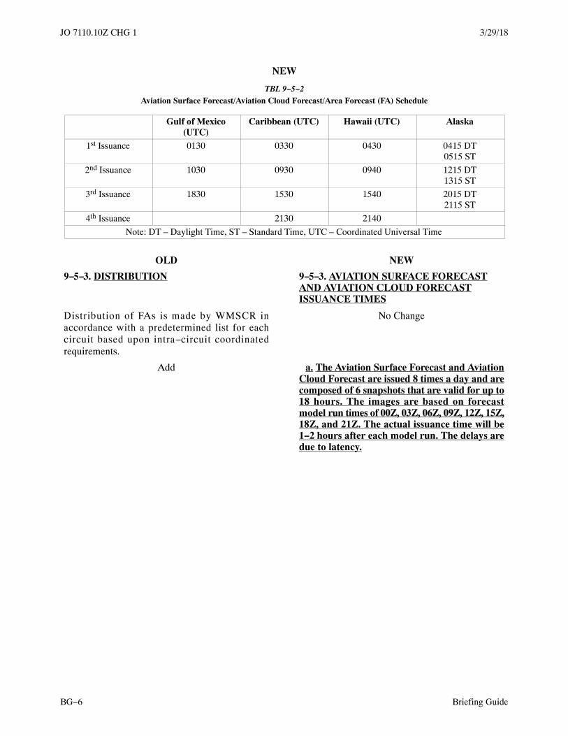
3/29/18JO 7110.10Z CHG 1
Briefing GuideBG−6
NEW
TBL 9−5−2Aviation Surface Forecast/Aviation Cloud Forecast/Area Forecast (FA) Schedule
Gulf of Mexico(UTC)
Caribbean (UTC) Hawaii (UTC) Alaska
1st Issuance 0130 0330 0430 0415 DT0515 ST
2nd Issuance 1030 0930 0940 1215 DT1315 ST
3rd Issuance 1830 1530 1540 2015 DT2115 ST
4th Issuance 2130 2140
Note: DT – Daylight Time, ST – Standard Time, UTC – Coordinated Universal Time
OLD NEW
9−5−3. DISTRIBUTION 9−5−3. AVIATION SURFACE FORECASTAND AVIATION CLOUD FORECASTISSUANCE TIMES
Distribution of FAs is made by WMSCR inaccordance with a predetermined list for eachcircuit based upon intra−circuit coordinatedrequirements.
No Change
Add a. The Aviation Surface Forecast and AviationCloud Forecast are issued 8 times a day and arecomposed of 6 snapshots that are valid for up to18 hours. The images are based on forecastmodel run times of 00Z, 03Z, 06Z, 09Z, 12Z, 15Z,18Z, and 21Z. The actual issuance time will be1−2 hours after each model run. The delays aredue to latency.

3/29/18 JO 7110.10Z CHG 1
Briefing Guide BG−7
Add
FIG 9−5−1Graphic Forecast Images
1. PARAGRAPH NUMBER AND TITLE: 10−1−9. SIMULTANEOUS APPROACH AND RUNWAYEDGE LIGHT OPERATION
2. BACKGROUND: Paragraph 10−1−9 requires controllers to turn on runway edge lights for the runway inuse whenever the associated approach lights are on. There are occasions where the runway edge lights are notspecifically required yet the approach lights must be on. The applicable setting(s) chart(s) provide the appropriateuse and settings criterion.
3. CHANGE:
OLD NEW
10−1−9. SIMULTANEOUS APPROACH ANDRUNWAY EDGE LIGHT OPERATION
Delete
Turn on the runway edge lights for the runway inuse whenever the associated approach lights are on.If multiple runway light selection is not possible,you may leave the approach lights on and switch therunway lights to another runway to accommodateanother aircraft.
Delete
10−1−10 through 10−1−21 Renumber 10−1−9 through 10−1−20.


Federal AviationAdministration
JO 7110.10Z CHG 29/13/18
Initiated By: AJR−0Vice President, System Operations Services
BRIEFING GUIDEFE
DERAL AVI ATI O
N
AD
MI N I S T RAT IO
N
U.S. DEPARTMENT OF TRANSPORTATIONFEDERAL AVIATION ADMINISTRATION

9/13/18JO 7110.10Z CHG 2
Briefing GuideBG−2
Table of Contents
ParagraphNumber
Title Page
1−1−6 SUBMISSION CUTOFF AND EFFECTIVE DATES . . . . . . . . . . . . . . BG−3
1−1−8 RECOMMENDATIONS FOR PROCEDURAL CHANGES . . . . . . . . . . BG−3
3−1−4 WEATHER DISPLAY PRODUCTS . . . . . . . . . . . . . . . . . . . . . . . . . . . . BG−4
3−1−8 LOGGING PILOT BRIEFINGS . . . . . . . . . . . . . . . . . . . . . . . . . . . . . . BG−5
4−1−1 INFLIGHT SERVICES . . . . . . . . . . . . . . . . . . . . . . . . . . . . . . . . . . . . . BG−4
4−2−3 IFR/VFR/DVFR FLIGHT PLAN RECORDING . . . . . . . . . . . . . . . . . . BG−5
6−1−6 IFR/VFR/DVFR FLIGHT PLAN RECORDING . . . . . . . . . . . . . . . . . BG−5
9−2−14 PIREP FORMAT . . . . . . . . . . . . . . . . . . . . . . . . . . . . . . . . . . . . . . . . . . BG−6
12−1−8 WEATHER PHRASEOLOGY . . . . . . . . . . . . . . . . . . . . . . . . . . . . . . . BG−6

9/13/18 JO 7110.10Z CHG 2
Briefing Guide BG−3
1. PARAGRAPH NUMBER AND TITLE:1−1−6. SUBMISSION CUTOFF AND EFFECTIVE DATES1−1−8. RECOMMENDATIONS FOR PROCEDURAL CHANGES
2. BACKGROUND: FAA change−submitting organizations are unclear over the precise meaning of the“Cutoff Date for Submission” when it comes to submitting changes to cyclical orders and other publications.Many organizations assumed that changes could be submitted to the correspondence mailbox on, or close to, theCutoff Date for Submission and be incorporated into the next publication effective date. In reality, submittedchanges require additional time for coordination prior to the cutoff date.
3. CHANGE:
OLD NEW
1−1−6. SUBMISSION CUTOFF ANDEFFECTIVE DATES
1−1−6. EFFECTIVE DATES ANDSUBMISSIONS FOR CHANGES
This order and its changes are scheduled to bepublished to coincide with AIRAC dates. Theeffective dates will be:
a. This order and its changes are scheduled to bepublished to coincide with AIRAC dates,according to the table below.
Add b. The “Cutoff Date for Completion” in thetable below refers to the deadline for a proposedchange to be fully coordinated and signed.Change initiators must submit their proposedchanges well in advance of this cutoff date tomeet the publication effective date. The processto review and coordinate changes often takesseveral months after the change is initiallysubmitted.
OLD
Publication ScheduleBasic orChange
Cutoff Date forSubmission
Effective Dateof Publication
JO 7110.10Z 4/27/17 10/12/17
Change 1 10/12/17 3/29/18
Change 2 3/29/18 9/13/18
Change 3 9/13/18 2/28/19
JO 7110.10AA 2/28/19 8/15/19
NEW
Publication ScheduleBasic orChange
Cutoff Date forCompletion
Effective Dateof Publication
JO 7110.10Z 4/27/17 10/12/17
Change 1 10/12/17 3/29/18Change 2 3/29/18 9/13/18
Change 3 9/13/18 2/28/19
JO 7110.10AA 2/28/19 8/15/19

9/13/18JO 7110.10Z CHG 2
Briefing GuideBG−4
OLD NEW
1−1−8. RECOMMENDATIONS FORPROCEDURAL CHANGES
1−1−8. RECOMMENDATIONS FORPROCEDURAL CHANGES
Title through b No Change
c. Proposed changes must be submittedelectronically to the Air Traffic ProceduresMailbox at9−JAV−8−[email protected]. Thesubmission should include a description of therecommended change and the proposed language tobe used in the order.
No Change
Add NOTE−For details on the submission process as well as addi-tional AJV−8 processing responsibilities, please seeFAA Order JO 7000.5, Procedures for SubmittingChanges to Air Traffic Control Publications.
1. PARAGRAPH NUMBER AND TITLE:3−1−4. WEATHER DISPLAY PRODUCTS4−1−1. INFLIGHT SERVICES
2. BACKGROUND: En Route Flight Advisory Service (EFAS) responsibilities were migrated into Inflight.EFAS weather display information required for flight watch should have been migrated to Chapter 3, PilotBriefing, but was inadvertently omitted in FAA Order JO 7110.10Y, Change 1. In addition, Current Icing Product(CIP), Forecast Icing Product (FIP), and Graphical Turbulence Guidance (GTC) were optional weather displayproducts in FAA Order JO 7110.10Y, Change 2; in Change 3 they became mandatory.
3. CHANGE:
OLD NEW
3−1−4. WEATHER DISPLAY PRODUCTS 3−1−4. WEATHER DISPLAY PRODUCTS
Title through a8 No Change
9. *Current Icing Product (CIP). 9. Current Icing Product (CIP).
10. *Forecast Icing Product (FIP). 10. Forecast Icing Product (FIP).
11. *Graphical Turbulence Guidance (GTG). 11. Graphical Turbulence Guidance (GTG).
Add 12. National Weather Radar Summary.(CONUS Only).
12. National/Regional Radar Mosaics. 13. National/Regional Radar Mosaics.
13. Radar Echo Tops. 14. Radar Echo Tops.
14. Radar VAD Wind Profiles. 15. Radar VAD Wind Profiles.
15. Visible/IR Satellite Imagery. 16. Visible/IR Satellite Imagery.
16. Constant Pressure Charts. 17. Constant Pressure Charts.
Add 18. 500 MB Heights and Vorticity Analysis.
Add 19. 500 MB Heights and Vorticity Prognosis.

9/13/18 JO 7110.10Z CHG 2
Briefing Guide BG−5
Add 20. 6−, 12−, 24−, 36−, and 48−hour 500 MBHeights and Vorticity Prognosis.
Add 21. Convective Outlook.
Add 22. Maximum Temperature 24− and36−Hour Forecast (CONUS Only).
Add 23. Minimum Temperature 24− and 36−HourForecast (CONUS Only).
NOTE−*Denotes weather products that are supplementary.They may only be used to enhance situational awareness.When discrepancies are noted, the specialist must basetheir decision on the primary weather product.
Delete
OLD NEW
4−1−1. INFLIGHT SERVICES 4−1−1. INFLIGHT SERVICES
Title through b NOTE No Change
Add c. Prior to assuming inflight duties, thespecialist must review, as a minimum, thegraphic information listed in subparagraph3−1−4a (if available). After assuming duties, thespecialist must continue to review graphic andwritten data as needed during the watch toupdate and maintain a thorough knowledge ofweather synoptic and forecast informationaffecting aviation operations.
1. PARAGRAPH NUMBER AND TITLE:3−1−8. LOGGING PILOT BRIEFINGS4−2−3. IFR/VFR/DVFR FLIGHT PLAN RECORDING6−1−6. IFR/VFR/DVFR FLIGHT PLAN RECORDING
2. BACKGROUND: The design of Federal Aviation Administration (FAA) Form 7233−1, Flight Plan, is notcompatible with non−United States (U.S.) flight data processing systems and requires manual intervention that isboth costly and time consuming. Additionally, FAA Form 7233−1 cannot provide the flight plan detail necessaryto gain benefits for system users that are being introduced through the FAA’s NextGen. In 2012, the U.S.increased the use of FAA Form 7233−4, International Flight Plan, which is compatible with domestic andinternational automation systems and is used for approximately 48 percent of all flight plans today. Tostreamline, standardize, and reduce the cost of flight plan processing within the U. S. and with international airnavigation service providers, civilian pilots will be required to file both IFR and VFR flight plans using FAAForm 7233−4, or its electronic equivalent, once the use of FAA Form 7233−1 ends. Additionally, NextGendeployment is fast approaching, and with it comes a number of enhancements which will benefit the aviationcommunity. In order to take advantage of these benefits, it has become necessary to add a level of detail to flightplans that current domestic flight plans lack. The use of the International Flight Plan Form will be mandatory forcivilian flight plans only.
3. CHANGE:
OLD NEW
3−1−8. LOGGING PILOT BRIEFINGS 3−1−8. LOGGING PILOT BRIEFINGS

9/13/18JO 7110.10Z CHG 2
Briefing GuideBG−6
Title through c1 No Change
2. FAA Form 7233−1, Flight Plan Form. Checkthe “pilot briefing” block, fill in specialist’s initials,and note the time started. As applicable, also enterAB, OTLK, and/or check the VNR block.
Delete
c3 Renumber as c2.
OLD NEW
4−2−3. IFR/VFR/DVFR FLIGHT PLANRECORDING
4−2−3. IFR/VFR/DVFR FLIGHT PLANRECORDING
a. Use the operational system to record and fileflight plans, flight plan modifications,cancellations, activations, and closures forappropriate distribution and processing. Detailedinstructions are contained in the operational systemmanuals.
No Change
NOTE−FSS operational systems contain an electronic equiva-lent of FAA Form 7233−1, Flight Plan.
NOTE−FSS operational systems contain an electronic equiva-lent of authorized FAA Flight Plan Forms.
OLD NEW
6−1−6. IFR/VFR/DVFR FLIGHT PLANRECORDING
6−1−6. IFR/VFR/DVFR FLIGHT PLANRECORDING
a. Use the operational system to record and fileflight plans, flight plan modifications,cancellations, activations, and closures forappropriate distribution and processing. Detailedinstructions are contained in the operational systemmanuals.
No Change
NOTE−FSS operational systems contain an electronic equiva-lent of FAA Form 7233−1, Flight Plan.
NOTE−FSS operational systems contain an electronic equiva-lent of authorized FAA Flight Plan Forms.
1. PARAGRAPH NUMBER AND TITLE:9−2−14. PIREP FORMAT12−1−8. WEATHER PHRASEOLOGY
2. BACKGROUND: The FAA provides annual guidance to operators regarding de−icing and anti−icingoperations. This guidance includes Allowance Times and Hold−Over Times (HOT) for different types ofde−icing and anti−icing fluids based on several factors, including the presence and type of frozen precipitation.Operators with FAA−approved de−icing/anti−icing programs require frozen precipitation observations andforecasts to support winter weather operations. Airlines for America (A4A), an industry group that advocates forU.S.−certified air carriers, requested that FAA examine the continued use of the meteorological identifier “GS” toreport both small hail and snow pellets. Recently, there has been a change in the FAA Hold−Over TimesGuidelines for anti/de−icing of small hail and ice pellets. Users are now required to note that small hail and icepellets are equivalent and cannot assume that GS is only snow pellets i.e., operators must assume, when they see

9/13/18 JO 7110.10Z CHG 2
Briefing Guide BG−7
GS, that it contains small hail. Thus, when “GS” is reported or forecast, operators must use the more conservativeAllowance Times for ice pellets and small hail. This can have a significant impact on operations. Changing thedefinition of “GS” so that GS refers only to snow pellets will lead to more efficient and cost effective winteroperations for airlines when snow pellets are observed and not small hail.
3. CHANGE:
OLD NEW
9−2−14. PIREP FORMAT 9−2−14. PIREP FORMAT
Title through g1 No Change
2. Enter flight weather types using one or moreof the standard surface weather reporting symbolscontained in TBL 9−2−1.
No Change
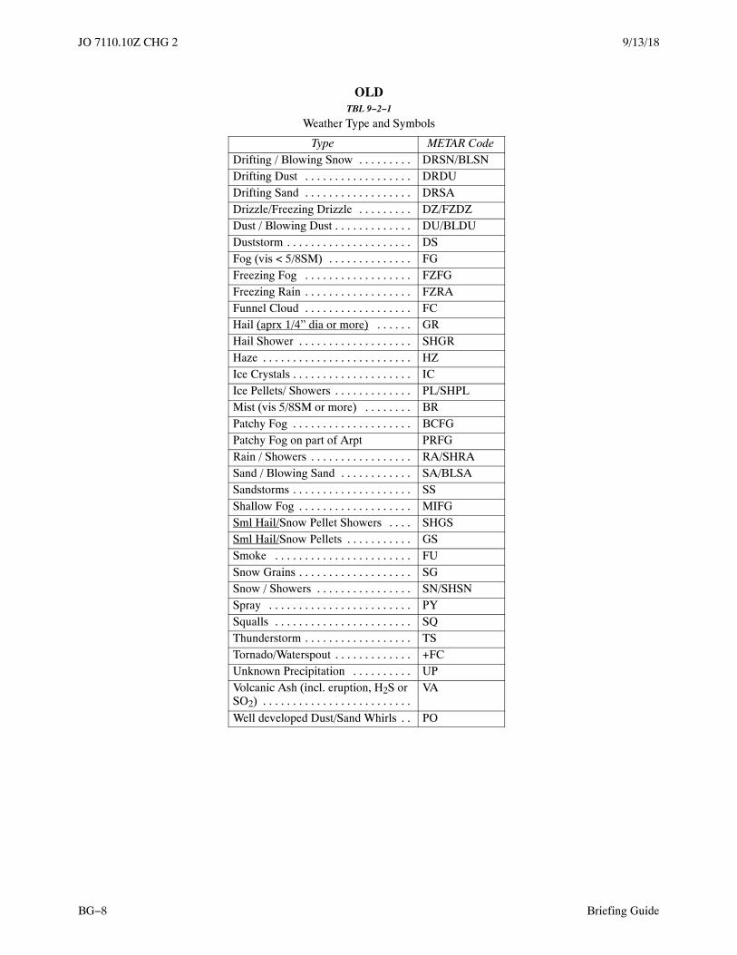
9/13/18JO 7110.10Z CHG 2
Briefing GuideBG−8
OLDTBL 9−2−1
Weather Type and Symbols
Type METAR CodeDrifting / Blowing Snow . . . . . . . . . DRSN/BLSNDrifting Dust . . . . . . . . . . . . . . . . . . DRDUDrifting Sand . . . . . . . . . . . . . . . . . . DRSADrizzle/Freezing Drizzle . . . . . . . . . DZ/FZDZDust / Blowing Dust . . . . . . . . . . . . . DU/BLDUDuststorm . . . . . . . . . . . . . . . . . . . . . DSFog (vis < 5/8SM) . . . . . . . . . . . . . . FGFreezing Fog . . . . . . . . . . . . . . . . . . FZFGFreezing Rain . . . . . . . . . . . . . . . . . . FZRAFunnel Cloud . . . . . . . . . . . . . . . . . . FCHail (aprx 1/4” dia or more) . . . . . . GRHail Shower . . . . . . . . . . . . . . . . . . . SHGRHaze . . . . . . . . . . . . . . . . . . . . . . . . . HZIce Crystals . . . . . . . . . . . . . . . . . . . . ICIce Pellets/ Showers . . . . . . . . . . . . . PL/SHPLMist (vis 5/8SM or more) . . . . . . . . BRPatchy Fog . . . . . . . . . . . . . . . . . . . . BCFGPatchy Fog on part of Arpt PRFGRain / Showers . . . . . . . . . . . . . . . . . RA/SHRASand / Blowing Sand . . . . . . . . . . . . SA/BLSASandstorms . . . . . . . . . . . . . . . . . . . . SSShallow Fog . . . . . . . . . . . . . . . . . . . MIFGSml Hail/Snow Pellet Showers . . . . SHGSSml Hail/Snow Pellets . . . . . . . . . . . GSSmoke . . . . . . . . . . . . . . . . . . . . . . . FUSnow Grains . . . . . . . . . . . . . . . . . . . SGSnow / Showers . . . . . . . . . . . . . . . . SN/SHSNSpray . . . . . . . . . . . . . . . . . . . . . . . . PYSqualls . . . . . . . . . . . . . . . . . . . . . . . SQThunderstorm . . . . . . . . . . . . . . . . . . TSTornado/Waterspout . . . . . . . . . . . . . +FCUnknown Precipitation . . . . . . . . . . UPVolcanic Ash (incl. eruption, H2S orSO2) . . . . . . . . . . . . . . . . . . . . . . . . .
VA
Well developed Dust/Sand Whirls . . PO

9/13/18 JO 7110.10Z CHG 2
Briefing Guide BG−9
NEW
TBL 9−2−1
Weather Type and SymbolsType METAR Code
Drifting / Blowing Snow . . . . . . . . . DRSN/BLSN
Drifting Dust . . . . . . . . . . . . . . . . . . DRDU
Drifting Sand . . . . . . . . . . . . . . . . . . DRSA
Drizzle/Freezing Drizzle . . . . . . . . . DZ/FZDZ
Dust / Blowing Dust . . . . . . . . . . . . . DU/BLDU
Duststorm . . . . . . . . . . . . . . . . . . . . . DS
Fog (vis < 5/8SM) . . . . . . . . . . . . . . FG
Freezing Fog . . . . . . . . . . . . . . . . . . FZFG
Freezing Rain . . . . . . . . . . . . . . . . . . FZRA
Funnel Cloud . . . . . . . . . . . . . . . . . . FC
Hail . . . . . . . . . . . . . . . . . . . . . . . . . GR
Hail Shower . . . . . . . . . . . . . . . . . . . SHGR
Haze . . . . . . . . . . . . . . . . . . . . . . . . . HZ
Ice Crystals . . . . . . . . . . . . . . . . . . . . IC
Ice Pellets/ Showers . . . . . . . . . . . . . PL/SHPL
Mist (vis 5/8SM or more) . . . . . . . . BR
Patchy Fog . . . . . . . . . . . . . . . . . . . . BCFG
Patchy Fog on part of Arpt PRFG
Rain / Showers . . . . . . . . . . . . . . . . . RA/SHRA
Sand / Blowing Sand . . . . . . . . . . . . SA/BLSA
Sandstorms . . . . . . . . . . . . . . . . . . . . SS
Shallow Fog . . . . . . . . . . . . . . . . . . . MIFG
Snow Pellet Showers . . . . . . . . . . . . SHGS
Snow Pellets . . . . . . . . . . . . . . . . . . . GS
Smoke . . . . . . . . . . . . . . . . . . . . . . . FU
Snow Grains . . . . . . . . . . . . . . . . . . . SG
Snow / Showers . . . . . . . . . . . . . . . . SN/SHSN
Spray . . . . . . . . . . . . . . . . . . . . . . . . PY
Squalls . . . . . . . . . . . . . . . . . . . . . . . SQ
Thunderstorm . . . . . . . . . . . . . . . . . . TS
Tornado/Waterspout . . . . . . . . . . . . . +FC
Unknown Precipitation . . . . . . . . . . UP
Volcanic Ash (incl. eruption, H2S orSO2) . . . . . . . . . . . . . . . . . . . . . . . . .
VA
Well developed Dust/Sand Whirls . . PO
G3 through g6 EXAMPLE No Change
7. When the size of hail is stated, enter in ¼”increments in remarks /RM TEI.
7. State the size of the hail in remarks in ¼”increments or any hail less than ¼” is stated as“GR less than ¼”.

9/13/18JO 7110.10Z CHG 2
Briefing GuideBG−10
OLD NEW
12−1−8. WEATHER PHRASEOLOGY 12−1−8. WEATHER PHRASEOLOGY
Title through h TBL 12−1−6 No Change
OLD
TBL 12−1−7
Weather Elements
INTENSITYor
PROXIMITY1
DESCRIPTOR
2
PRECIPITATION
3
OBSCURATION
4
OTHER
5
− Light MI Shallow DZ Drizzle BR Mist PO Well−DevelopedDust/SandWhirls
BC Patchy RA Rain FG Fog SQ Squalls
Moderate(No Qualifier)
DR Low Drifting SN Snow FU Smoke FC+FC
Funnel Cloud,Tornado orWaterspout
BL Blowing SG Snow Grains DU Dust SS Sandstorm
+ Heavy SH Showers IC Ice Crystals SA Sand DS Duststorm
TS Thunderstorm PL Ice Pellets HZ Haze
VC In the Vicinity FZ Freezing GR Hail PY Spray
PR Partial GS Small Hail orSnow Pellets(�1/4”)
VA Volcanic Ash
UP *UnknownPrecipitation
* Automated stations only.

9/13/18 JO 7110.10Z CHG 2
Briefing Guide BG−11
NEW
TBL 12−1−7
Weather Elements
INTENSITYor
PROXIMITY1
DESCRIPTOR
2
PRECIPITATION
3
OBSCURATION
4
OTHER
5
− Light MI Shallow DZ Drizzle BR Mist PO Well−DevelopedDust/SandWhirls
BC Patchy RA Rain FG Fog SQ Squalls
Moderate(No Qualifier)
DR Low Drifting SN Snow FU Smoke FC+FC
Funnel Cloud,Tornado orWaterspout
BL Blowing SG Snow Grains DU Dust SS Sandstorm
+ Heavy SH Showers IC Ice Crystals SA Sand DS Duststorm
TS Thunderstorm PL Ice Pellets HZ Haze
VC In the Vicinity FZ Freezing GR Hail PY Spray
PR Partial GS Snow Pellets VA Volcanic Ash
UP *UnknownPrecipitation
* Automated stations only.

Federal AviationAdministration
JO 7110.10Z CHG 32/28/19
Initiated By: AJR−0Vice President, System Operations Services
BRIEFING GUIDEFE
DERAL AVI ATI O
N
AD
MI N I S T RAT IO
N
U.S. DEPARTMENT OF TRANSPORTATIONFEDERAL AVIATION ADMINISTRATION

2/28/19JO 7110.10Z CHG 3
Briefing GuideBG−2
Table of Contents
ParagraphNumber
Title Page
2−1−1 TYPES OF BROADCASTS . . . . . . . . . . . . . . . . . . . . . . . . . . . . . . . . . . BG−3
2−1−3 REDUCING RECORDED WEATHER INFORMATION SERVICES . BG−3
2−3−1 GENERAL . . . . . . . . . . . . . . . . . . . . . . . . . . . . . . . . . . . . . . . . . . . . . . . . BG−3
3−2−1 CONDUCT OF STANDARD BRIEFING . . . . . . . . . . . . . . . . . . . . . . . BG−4
4−3−7 ATC CLEARANCES, ADVISORIES, OR REQUESTS . . . . . . . . . . . . BG−5
7−1−1 GENERAL . . . . . . . . . . . . . . . . . . . . . . . . . . . . . . . . . . . . . . . . . . . . . . . . BG−7
7−2−1 FLIGHT PLAN/CUSTOMS REQUIREMENTS . . . . . . . . . . . . . . . . . . BG−7
7−2−2 INBOUND AIRCRAFT: CUSTOMS REQUIREMENTS . . . . . . . . . . . BG−7
7−2−3 INBOUND AIRCRAFT: ADIZ REQUIREMENTS . . . . . . . . . . . . . . . . BG−7
7−4−1 GENERAL . . . . . . . . . . . . . . . . . . . . . . . . . . . . . . . . . . . . . . . . . . . . . . . . BG−7
7−4−2 INBOUNDS FROM CANADA . . . . . . . . . . . . . . . . . . . . . . . . . . . . . . . BG−7
7−4−3 OUTBOUNDS TO CANADA . . . . . . . . . . . . . . . . . . . . . . . . . . . . . . . . BG−7
7−4−4 OUTBOUNDS TO CANADA DEPARTING FROM OUTSIDEFLIGHT PLAN AREA . . . . . . . . . . . . . . . . . . . . . . . . . . . . . . . . . . . . . .
BG−7
7−5−1 GENERAL . . . . . . . . . . . . . . . . . . . . . . . . . . . . . . . . . . . . . . . . . . . . . . . . BG−7
7−5−2 INBOUNDS FROM MEXICO . . . . . . . . . . . . . . . . . . . . . . . . . . . . . . . . BG−7
7−5−3 OUTBOUNDS TO MEXICO . . . . . . . . . . . . . . . . . . . . . . . . . . . . . . . . . BG−7
8−2−1 COMMUNICATIONS SEARCH . . . . . . . . . . . . . . . . . . . . . . . . . . . . . . BG−15
8−2−2 QALQ . . . . . . . . . . . . . . . . . . . . . . . . . . . . . . . . . . . . . . . . . . . . . . . . . . . BG−15
8−3−1 INREQ . . . . . . . . . . . . . . . . . . . . . . . . . . . . . . . . . . . . . . . . . . . . . . . . . . . BG−15
8−4−1 ALNOT . . . . . . . . . . . . . . . . . . . . . . . . . . . . . . . . . . . . . . . . . . . . . . . . . . BG−15
9−2−3 RESPONSIBILITY . . . . . . . . . . . . . . . . . . . . . . . . . . . . . . . . . . . . . . . . . BG−17
9−2−5 SOLICITING PIREPS . . . . . . . . . . . . . . . . . . . . . . . . . . . . . . . . . . . . . . . BG−17
9−2−14 PIREP FORMATTING . . . . . . . . . . . . . . . . . . . . . . . . . . . . . . . . . . . . . . BG−17
9−5−2 AVIATION SURFACE FORECAST/ AVIATION CLOUD FORE-CAST/ AREA FORECAST (FA) SCHEDULE . . . . . . . . . . . . . . . . . . .
BG−18
9−5−3 AVIATION SURFACE FORECAST AND AVIATION CLOUD FORE-CAST ISSUANCE TIMES . . . . . . . . . . . . . . . . . . . . . . . . . . . . . . . . . . .
BG−18
APPENDIX A ICAO FLIGHT PLANS . . . . . . . . . . . . . . . . . . . . . . . . . . . . . . . . . . . . . . BG−20

2/28/19 JO 7110.10Z CHG 3
Briefing Guide BG−3
1. PARAGRAPH NUMBER AND TITLE:2−1−1. TYPES OF BROADCASTS2−1−3. REDUCING RECORDED WEATHER INFORMATION SERVICES2−3−1. GENERAL
2. BACKGROUND: Flight Service has provided Telephone Information Briefings Service (TIBS) since theearly 1980s. Telephone recordings were produced by Flight Service specialists working the Broadcast position inorder to provide weather and aeronautical information that pilots could access without contacting a specialist.The recordings were tailored to fit the needs of an individual facility and its geographic location, and updated asnecessary. When these broadcasts were originally conceived there was a large demand for briefings from aspecialist and wait times could be extremely long.
At the time, when pilots had no other choice but to call Flight Service to obtain weather and NOTAMs for theroute of flight, TIBS alleviated the workload of the specialists and helped to reduce wait times for pilots.However, with the advent of the internet and other technology, the demand for the services of a Flight Servicespecialist has dropped considerably. From over 3,000 specialists in more than 300 facilities during the early1980s, staffing has decreased to fewer than 500 specialists in three facilities. Pilots no longer need to “call” aFlight Service specialist or listen to telephone recordings of route and area briefings containing aviation weatherand aeronautical information to adhere to 14 CFR 91.103. Currently, in the contiguous United States, Hawaii, andPuerto Rico there are multiple sources providing pilots access to weather and aeronautical information. Thisinformation, presented in a graphical format, makes it easier to visualize activity along their proposed route offlight; at little to no cost. This change does not apply in Alaska due to terrain features, weather conditions, andaccessibility limitations.
3. CHANGE:
OLD NEW
2−1−1. TYPES OF BROADCASTS 2−1−1. TYPES OF BROADCASTS
Weather and flight information must be broadcast/recorded by one or more of the followingcategories:
No Change
a. Transcribed Weather Broadcast (TWEB).(Alaska only.)
No Change
b. Telephone Information Briefing Service(TIBS).
b. Telephone Information Briefing Service(TIBS). (Alaska only.)
c. Hazardous Inflight Weather Advisory Service(HIWAS).
No Change
d. Automatic Flight Information Service (AFIS).(Alaska only.)
No Change
OLD NEW
2−1−3. REDUCING RECORDED WEATHERINFORMATION SERVICES
2−1−3. REDUCING RECORDED WEATHERINFORMATION SERVICES

2/28/19JO 7110.10Z CHG 3
Briefing GuideBG−4
Recorded weather information services (TWEBand TIBS) may be reduced during the hours of1800−0600 local time only. Adjust full broadcastservice times to coincide with daylight hours. Whena broadcast period is reduced, record the time thebroadcast will be resumed, and advise users tocontact flight service for weather briefings andother services.
Recorded weather information services in Alaska(TWEB and TIBS) may be reduced during thehours of 1800−0600 local time only. Adjust fullbroadcast service times to coincide with daylighthours. When a broadcast period is reduced, recordthe time the broadcast will be resumed, and adviseusers to contact flight service for weather briefingsand other services.
PHRASEOLOGY−THE TIBS RECORDING IS SUSPENDED. REGULARRECORDED WEATHER SERVICE WILL BE RE-SUMED AT (time) ZULU/ (time) LOCAL. FOR PILOTWEATHER BRIEFINGS AND OTHER SERVICES,CONTACT FLIGHT SERVICE (phone number or ad-ditional telephone instructions, as appropriate).THE TWEB RECORDING IS SUSPENDED. REGU-LAR RECORDED WEATHER SERVICE WILL BERESUMED AT (time) ZULU/ (time) LOCAL. FORPILOT WEATHER BRIEFING AND OTHER SER-VICES CONTACT FLIGHT SERVICE (frequency orphone number, as appropriate)
No Change
OLD NEW
2−3−1. GENERAL 2−3−1. GENERAL
Title through c No Change
EXAMPLE−11 Northeast Michigan 12 Southeast Michigan13 Southwest Michigan14 Northwest Michigan including the Upper Peninsula19 Aviation Events
EXAMPLE−11 Special Announcements12 Route FAI to GAL13 Route FAI to AKP14 Route FAI to FYU17 Current Weather – FAI−ANC18 Current Weather −Interior AK.
1. PARAGRAPH NUMBER AND TITLE: 3−2−1. CONDUCT OF STANDARD BRIEFING
2. BACKGROUND: To modernize the NAS, meet the needs of our stakeholders, and provide accurateNOTAM information, the FAA is removing Part 1 of the Notices to Airmen Publication (NTAP). This partcontains amendments to FDC NOTAMs that pertain to IFR routes and procedures. The NTAP currently containsmany inaccurate and outdated FDC NOTAMs as the publication cycle is 28 days and many NOTAMs arecancelled mid−cycle. This conflict causes safety concerns for pilots. The most current and up−to−dateinformation on NOTAMs is contained in the FAA’s official NOTAM Search website(https://notams.aim.faa.gov/notamSearch/) or through an approved Flight Service web portal. Pilots shouldobtain preflight IFR route and amendment FDC NOTAM information via the NOTAM Search website, anapproved Flight Service web portal, or upon request by calling a Flight Service Station.
3. CHANGE:
OLD NEW
3−2−1. CONDUCT OF STANDARDBRIEFING
3−2−1. CONDUCT OF STANDARDBRIEFING

2/28/19 JO 7110.10Z CHG 3
Briefing Guide BG−5
Title through c8(a) NOTE No Change
(b) Flight Data Center (FDC) NOTAMs notalready carried in the Notices to Airmenpublication.
Delete
(c) Combine this element with adverseconditions when it would be logical andadvantageous to do so.
(b) Combine this element with adverseconditions when it would be logical andadvantageous to do so.
c9 through c12(e) No Change
Add (f) FDC NOTAMs containing amendmentsto airways, airport, and facility IFR proceduresand General Information.
Add NOTE−General FDC NOTAMs include Chart amendments,Special Security Instructions, and Special AdvisoryNotices.
Add (g) Information contained in the Notices toAirmen Publication to include Part 95Revisions, International NOTAMs and GraphicNotices.
1. PARAGRAPH NUMBER AND TITLE: 4−3−7. ATC CLEARANCES, ADVISORIES, OR RE-QUESTS
2. BACKGROUND: Flight Service relays telephone clearances to pilots at airports that lack direct radiocommunications with air traffic control (ATC). Flight Service also relays cancellations of Instrument FlightRules (IFR) flight plans from pilots to ATC.
Except in Alaska, this change will discontinue Flight Service telephone relay of IFR clearances from all ATCfacilities and reduce the number of IFR flight plan cancellations handled by Flight Service.
Clearance Relay Part 1 formalized a process already in place by publishing phone numbers of approach controlfacilities in the Chart Supplement US. The initiative included 30 approach controls covering 667 airports,providing pilots direct contact with the controlling facility to obtain clearances and cancel IFR flight plans.Clearance Relay Part 2 enables pilots to obtain an IFR clearance and/or cancel IFR flight plans via telephone bycalling either:
1. The overlying Air Route Traffic Control Center (ARTCC) Flight Data Units (FDUs), which will then relaythe clearance from the appropriate sector, specialty or control facility to the pilot,
Or
2. An approach control facility with clearance delivery phone numbers published in the Chart Supplement US.
Pilots may continue to request clearances via radio from ATC or Leidos Flight Service (formerly LockheedMartin). The plan does not affect pilots requesting clearances from locations in Alaska.
Flight Service will continue to relay clearances to pilots via telephone until these phone numbers are published.

2/28/19JO 7110.10Z CHG 3
Briefing GuideBG−6
Once published, Flight Service will provide pilots with either the name of the facility to contact or the correctphone number to obtain a clearance. In addition, Flight Service will continue to provide priority handling forMedEvac/Life Flights.
3. CHANGE:
OLD NEW
4−3−7. ATC CLEARANCES, ADVISORIES,OR REQUESTS
4−3−7. ATC CLEARANCES, ADVISORIES,OR REQUESTS
a. Notify ATC via interphone of a pilot’s requestfor clearance and include the departure anddestination airports and, if appropriate, departingrunway and time in the request. Forward pilotrequests to execute the Visual Climb Over Airport(VCOA) procedure to ATC. Relay, verbatim, ATCclearances, advisories, and requests received fromthe control facility. Give a time check to the nearestquarter minute when relaying a clearance thatincludes a release or void time.
No Change
NOTE−For ATC clearances, ”verbatim” means exact controlinstructions in the format stated in FAA Order JO7110.65, Air Traffic Control, Chapter 4, Section 2,Clearances, and Section 3, Departure Procedures.
No Change
PHRASEOLOGY−Aircraft on the ground:
(Facility) RADIO, CLEARANCE REQUEST.
After go−ahead from ATC,
(Aircraft identification) DEPARTING (airport), RUN-WAY (number if applicable) DESTINATION (fix orairport). (If applicable), CAN BE OFF AT (time).
Aircraft airborne:
(Facility) RADIO, CLEARANCE REQUEST.
After go−ahead from ATC:
(Aircraft identification), (position), (altitude), (route),AND (destination).
PHRASEOLOGY−Aircraft on the ground:
(ARTCC facility’s name) Center FLIGHT DATA,CLEARANCE REQUESTor
(Facility) RADIO, CLEARANCE REQUEST.
After go−ahead from ATC,
(Aircraft identification) DEPARTING (airport),RUNWAY (number if applicable) DESTINATION (fix orairport). (If applicable), CAN BE OFF AT (time).
Aircraft airborne:
(Facility) RADIO, CLEARANCE REQUEST.
After go−ahead from ATC:
(Aircraft identification), (position), (altitude), (route),AND (destination).

2/28/19 JO 7110.10Z CHG 3
Briefing Guide BG−7
1. PARAGRAPH NUMBER AND TITLE:7−1−1. GENERAL7−2−1. FLIGHT PLAN/CUSTOMS REQUIREMENTS7−2−2. INBOUND AIRCRAFT: CUSTOMS REQUIREMENTS7−2−3. INBOUND AIRCRAFT: ADIZ REQUIREMENTS7−4−1. GENERAL7−4−2. INBOUNDS FROM CANADA7−4−3. OUTBOUNDS TO CANADA7−4−4. OUTBOUNDS TO CANADA DEPARTING FROM OUTSIDE FLIGHT PLAN AREA7−5−1. GENERAL7−5−2. INBOUNDS FROM MEXICO7−5−3. OUTBOUNDS TO MEXICO
2. BACKGROUND: In 2008, U.S. customs notification requirements for private pilots changed substantiallywhen U.S. Customs and Border Patrol (CBP) implemented regulations contained in 19 CFR 122. Of thesechanges, several are especially salient: One, private pilots must coordinate their passenger manifest directly withCBP to comply with Advance Passenger Information System (APIS) requirements a minimum of 24−hours inadvance of their departure, Two, before, customs notification requirements only applied to flights inbound to theU.S.; APIS requirements now apply to both inbound and outbound flights; Three, pilots are now required to get adecal from CBP to fly inbound or outbound, the decal number is a required element in the APIS manifest; Four,the use of advise customs (ADCUS) in remarks conflicts with CBP requirements in 19 CFR 122 and is nowobsolete. Five, APIS requirements apply to flights to and from Canada and Mexico. There are no longeralternative U.S. customs notification procedures for either country.
3. CHANGE:
OLD NEW
7−1−1. GENERAL 7−1−1. GENERAL

2/28/19JO 7110.10Z CHG 3
Briefing GuideBG−8
a. Title 14 of the U.S. Code of FederalRegulations (14 CFR) and the International CivilAviation Organization (ICAO) require flight plansfor all civil aircraft operation between the UnitedStates and foreign locations. Bureau of Customsand Border Protection requirements, internationalflight plan information, and ADIZ penetrationrequirements are listed in other publications; forexample, the FAA International Flight InformationManual (IFIM), the Bureau of Customs and BorderProtection Guide for Private Flyers, theAeronautical Information Manual (AIM),Aeronautical Information Publication (AIP), 14CFR Part 91, and 14 CFR Part 99. Landing RightsAirports (LRA) and Airports of Entry (AOE) arelisted in the Chart Supplement U.S.
a. Title 19 of the U.S. Code of FederalRegulations (CFR), Part 122 contains AdvancePassenger Information System (APIS)regulations, which require APIS manifests to besubmitted to U.S. Customs and BorderProtection (CBP) for all private aircraftarriving from or departing for a foreign port orplace. APIS regulations also require thatelectronic notices of arrival and departure aswell as electronic manifests relative to travelers(passengers and crew) be submitted to CBPwithin specific timeframes. For detailedinformation on the APIS regulations, seeAdvance Information on Private AircraftArriving and Departing the United States, 73Fed. Reg. 68,295 (Nov. 18, 2008) (19 CFR122.22). This publication, along with otherresources, is available at http://www.cbp.gov. Inaddition, 14 CFR and the International CivilAviation Organization (ICAO) require flightplans for all civil aircraft operation between theUnited States and foreign locations.International flight plan information and ADIZpenetration requirements are listed in otherpublications; for example, the AeronauticalInformation Manual (AIM), the AeronauticalInformation Publication (AIP), 14 CFR Part 91,and 14 CFR Part 99.
b through d No Change
e. Use of FAA Form 7233−4 is mandatory for allIFR flights that will depart U.S. domestic airspaceand enter international airspace. The filer isresponsible for providing the information requiredin items 3 through 19.
e. Use of FAA Form 7233−4 is mandatory for allIFR flights that will depart U.S. controlled airspaceand enter international airspace. The filer isresponsible for providing the information requiredin items 3 through 19.
OLD NEW
7−2−1. FLIGHT PLAN/CUSTOMSREQUIREMENTS
7−2−1. FLIGHT PLAN/CUSTOMSREQUIREMENTS
Specific flight plan, Customs, and other require-ments of individual countries are listed in the FAAInternational Flight Information Manual, IFIM.
Delete

2/28/19 JO 7110.10Z CHG 3
Briefing Guide BG−9
Add a. U.S. Customs and Border Protection (CBP)requirements for Advance PassengerInformation System (APIS) authorizations arecontained in 19 CFR 122 and apply to bothinbound and outbound aircraft. Do not includeADCUS in flight plan remarks; pilots arerequired to coordinate directly with CBP.
Add b. Flight plan and customs requirements forother countries are usually contained in thatcountry’s Aeronautical InformationPublication (AIP).
OLD NEW
7−2−2. INBOUND AIRCRAFT: CUSTOMSREQUIREMENTS
7−2−2. CUSTOMS REQUIREMENTS FORINBOUND AND OUTBOUND AIRCRAFT
a. All aircraft entering U.S. airspace from aforeign port must provide at least 1 hour advancenotice to the U.S. Customs and Border Protection(CBP) at the point of first intended landing.
Delete
b. Aircraft arriving from the following locationmust furnish a notice of intended arrival to CBP atthe nearest designated airport to point of crossingfor the first landing in the U.S.
Delete
1. Via the U.S./Mexican border or the PacificCoast from a foreign location in the WesternHemisphere south of 33 degrees north latitude.
Delete
2. From the Gulf of Mexico or the AtlanticCoasts from a place in the Western Hemispheresouth of 30 degrees north latitude from any place inMexico.
Delete
3. From the U.S. Virgin Islands. Delete
4. From Puerto Rico, which if from Puerto Rico,are conducting VFR flight.
Delete
c. This notice must be given at least 1 hour beforecrossing the U.S. coastline or border. The advancenotice of arrival must include the following:
Delete
1. Aircraft registration number. Delete
2. Name of aircraft commander. Delete
3. Number of U.S. citizen passengers. Delete
4. Number of alien passengers. Delete
5. Place of last departure. Delete
6. Estimated time and location of crossing U.S.border/coastline.
Delete
7. Estimated time of arrival. Delete
8. Name of intended U.S. airport of first landing. Delete

2/28/19JO 7110.10Z CHG 3
Briefing GuideBG−10
d. The pilot may make any required notificationdirectly to the CBP through the Electronic AdvancePassenger Information System (eAPIS) at:https://eapis.cbp.dhs.gov/. Alternate methods mayinclude telephone, radio, or other means, or may befurnished through the FAA to the CBP.
Delete
REFERENCE−U.S. Customs and Border Protection Guide for Private Flyers.
Delete
e. When Customs flight notification service isrequested, as indicated by inclusion of ADCUS inremarks, deliver the complete message to theassociated CBP office as soon as practical. Relayadditional or amended information to the CBP inorder to properly comply with requirements; forexample, when actual arrival time varies from ETAby more than 15 minutes.
Delete
1. Provide the service only for those airportswhere availability is advertised in the AFD on flightnotification messages. Pilots are responsible formaking their own Customs arrangements for otherairports.
Delete
2. Notify only the CBP office which, in turn, isresponsible for notifying other inspection agenciesconcerned.
Delete
f. Prefiled Customs notification requests forflights returning to the U.S. must be delivered to theCBP office not earlier than 23 hours in advance.
Delete
g. When an airborne aircraft identifies an airportof first intended landing that is not one of thedesignated airports, advise the pilot that this airportis not a designated airport of first landing.
Delete
PHRASEOLOGY−BE ADVISED THAT YOUR DESTINATION IS NOT ACUSTOMS AND BORDER PROTECTION DESIG-NATED FIRST LANDING AIRPORT. WHAT AREYOUR INTENTIONS?
Delete
NOTE−If a pilot insists on landing at a non−designated air-port, pass this information to nearest Customs andBorder Protection office.
Delete
h. When a flight notification message containingADCUS in remarks identifies a non−designatedairport of first intended landing, notify the messageoriginator to advise the pilot that the fileddestination is not a designated airport.
Delete

2/28/19 JO 7110.10Z CHG 3
Briefing Guide BG−11
PHRASEOLOGY−ADVISE (aircraft identification) THAT THE FILEDDESTINATION IS NOT A CUSTOMS AND BORDERPROTECTION DESIGNATED FIRST LANDING AIR-PORT.
Delete
NOTE−The FAA’s role in this program is advisory only. Anyappearance of action of enforcing compliance must beavoided. Any questions should be directed to the U.S.Customs and Border Protection.
Delete
i. Record the time of receipt of Customs requests.This time will constitute evidence of the pilot’sintention to comply with CBP, Immigration, andPublic Health requirements and will be madeavailable upon request from these authorities.
Delete
Add 19 CFR Part 122 contains Advance PassengerInformation System (APIS) regulations whichrequire APIS manifests to be submitted to U.S.Customs and Border Protection (CBP) for allprivate aircraft arriving from or departing fora foreign port or place. APIS regulations alsorequire that electronic notices of arrival anddeparture as well as electronic manifests relativeto travelers (passengers and crew) be submittedto CBP within specific timeframes. For detailedinformation on the APIS regulations, seeAdvance Information on Private AircraftArriving and Departing the United States, 73Fed. Reg. 68,295 (Nov. 18, 2008) (19 CFR122.22). This publication, along with otherresources, is available at http://www.cbp.gov.
Add a. All aircraft entering U.S. airspace from aforeign port or departing U.S. airspace for aforeign port must provide at least 1 houradvance notice to the U.S. Customs and BorderProtection (CBP) via the Electronic APIS(eAPIS).
Add b. Pilots of aircraft inbound to the U.S. from aforeign port are required to notify CBP of anychanges to their ETA which are 15 minutes orgreater. Upon pilot request, relay changes inETA to CBP.
OLD NEW
7−2−3. INBOUND AIRCRAFT: ADIZREQUIREMENTS
7−2−3. ADIZ REQUIREMENTS FORINBOUND AND OUTBOUND AIRCRAFT
Title through b NOTE No Change

2/28/19JO 7110.10Z CHG 3
Briefing GuideBG−12
c. Pilots of aircraft entering the United Statesthrough an ADIZ are required to comply with theprovisions of 14 CFR Sections 99.17 and 99.19.
c. A person who operates a civil aircraft into anADIZ must have a functioning two−way radio,and the pilot must maintain a continuouslistening watch on the appropriate aeronauticalfacility’s frequency.
Add d. Pilots of aircraft entering or departing theUnited States through an ADIZ, or operatingwithin an ADIZ, are required to comply with theprovisions of 14 CFR 99.
d. Forward information on DVFR aircraftinbound to the U.S. to NORAD via Service B or bytelephone. Forward the following information:
e. Forward information on DVFR aircraftinbound to the U.S. to NORAD via Service B or bytelephone. Forward the following information:
d1 through d9 EXAMPLE No Change
NOTE−1. See para 6−3−3, IFR Flight Plan Control Messages.2. Further information on ADIZ requirements is con-tained in 14 CFR Part 99.
NOTE−See para 6−3−3, IFR Flight Plan Control Messages.
OLD NEW
7−4−1. GENERAL 7−4−1. GENERAL
Except as indicated in this section, handleTransborder Canadian movement and controlmessages as described in Sections 1, 2, and 3. Donot include ADCUS in flight plan remarks becauseNAV CANADA no longer alerts CanadianCustoms. CANPASS authorizations are the obliga-tion of the pilot, at the number in subpara 7−4−3a.
Except as indicated in this section, handleTransborder Canadian movement and controlmessages as described in Sections 1, 2, and 3. Donot include ADCUS in flight plan remarks forflight plans to Canada because NAV CANADAno longer alerts Canadian Customs. CANPASSauthorizations are the obligation of the pilot, at thenumber in subpara 7−4−3a. Do not includeADCUS in flight plan remarks for flights plansfrom Canada to the United States because U.S.flight service no longer alerts U.S. Customs andBorder Patrol (CBP). U.S. Advance PassengerInformation System (APIS) authorizations arethe obligation of the pilot for flights departingand entering the U.S., as stated in 19 CFR 122.APIS resources for pilots are available athttp://www.cbp.gov.
OLD NEW
7−4−2. INBOUNDS FROM CANADA 7−4−2. INBOUNDS FROM CANADA

2/28/19 JO 7110.10Z CHG 3
Briefing Guide BG−13
a. Do not accept VFR flight plans other than airfiled flight plans for aircraft departing fromCanada. Refer individuals to the appropriateNAVCANADA facility to file flight plans out ofCanada. Do not accept round−robin flight plans tointernational locations, other than Canada.
No Change
b. The operational system should automaticallyformat the required items of the flight notificationmessage when activated. Deliver VFR and IFRADCUS to the CBP. File IFR messages afterdelivery.
b. The operational system should automaticallyformat the required items of the flight notificationmessage when activated. U.S. CBP authorizationsfor flights inbound to the U.S. from Canada arethe obligation of the pilot and must be obtainedvia the APIS process. APIS resources for pilotsare available at http://www.cbp.gov.
OLD NEW
7−4−3. OUTBOUNDS TO CANADA 7−4−3. OUTBOUNDS TO CANADA
a. When Customs notification service is requestedadvise the pilot to contact Canada’s Private AircraftProgram for Customs (CANPASS) at888−226−7277 and include CANPASS in theremarks section of the flight plan. If the pilotinforms that he/she has contacted CANPASS, placeCANPASS in the remarks section of the flight plan.Process outbound flight plans in accordance withChapter 6 and subparas 7−4−3d and e.
No Change
Add NOTE−U.S. CBP authorizations for flights outbound fromthe U.S. to Canada are the obligation of the pilot andmust be obtained via the APIS process. APIS re-sources for pilots are available at http://www.cbp.gov.
OLD NEW
7−4−4. OUTBOUNDS TO CANADADEPARTING FROM OUTSIDE FLIGHTPLAN AREA
7−4−4. OUTBOUNDS TO CANADADEPARTING FROM OUTSIDE FLIGHTPLAN AREA
Title through a6 EXAMPLE No Change
Add NOTE−U.S. CBP authorizations for flights outbound fromthe U.S. to Canada are the obligation of the pilot andmust be obtained via the APIS process. APIS re-sources for pilots are available at http://www.cbp.gov.
OLD NEW
7−5−1. GENERAL 7−5−1. GENERAL

2/28/19JO 7110.10Z CHG 3
Briefing GuideBG−14
Except as outlined in this section, handletransborder Mexican movement and controlmessages as described in Sections 1, 2, and 3. IFRflight plans to Mexico require the ICAO flight planform.
a. Except as outlined in this section, handletransborder Mexican movement and controlmessages as described in Sections 1, 2, and 3. IFRflight plans to Mexico require the ICAO flight planform.
Add b. Do not include ADCUS in flight planremarks for flight plans to Mexico; MexicanCustoms authorizations are the obligation of thepilot. Do not include ADCUS in flight planremarks for flights plans from Mexico to theUnited States because U.S. flight service nolonger alerts U.S Customs and Border Patrol(CBP). U.S. APIS authorizations are theobligation of the pilot for flights departing andentering the U.S., as stated in 19 CFR 122. APISresources for pilots are available athttp://www.cbp.gov.
OLD NEW
7−5−2. INBOUNDS FROM MEXICO 7−5−2. INBOUNDS FROM MEXICO
a. Flight notification messages. No Change
1. When received in the proper format, VFRflight notification messages are automaticallyacknowledged and suspended by the operationalsystem. Deliver VFR and IFR ADCUS messages toCBP. Store IFR ADCUS messages in the historyfile, as appropriate.
1. When received in the proper format, VFRflight notification messages are automaticallyacknowledged and suspended by the operationalsystem.
2. Acknowledge receipt of a flight notificationmessage as soon as practical by transmitting theletter R followed by the full ACID; e.g., R N7llVR.Deliver VFR and IFR ADCUS messages to CBP.Suspense VFR flight notification messages untilarrival or closure information is received. File IFRmessages. Remove IFR inbounds from Mexicofrom the inbound list once ADCUS message isdelivered to CBP.
2. Acknowledge receipt of a flight notificationmessage as soon as practical by transmitting theletter R followed by the full ACID; e.g., R N7llVR.Suspense VFR flight notification messages untilarrival or closure information is received. File IFRmessages.
OLD NEW
7−5−3. OUTBOUNDS TO MEXICO 7−5−3. OUTBOUNDS TO MEXICO
a. When customs notification service is requestedfor an airport−of−entry, include ADCUS, thenumber of persons on board, and the pilot’s namein the remarks section of the flight plan.
a. Mexican customs notification is theobligation of the pilot. U.S. CBP authorizationsfor flights outbound from the U.S. to Mexico arealso the obligation of the pilot and must beobtained via the APIS process. APIS resourcesfor pilots are available at http://www.cbp.gov.
a NOTE through a2 NOTE No Change

2/28/19 JO 7110.10Z CHG 3
Briefing Guide BG−15
b. When a pilot files an IFR flight plan andcustoms notification service is requested for anairport−of−entry, include ADCUS and theinformation listed in subpara 7−5−3a. Transmit tothe appropriate ARTCC.
Delete
NOTE−Mexico requires notification of an inbound aircraftbefore its arrival. The inclusion of ADCUS in the re-marks section of an IFR flight plan or flight notifica-tion message satisfies this requirement.
Delete
c. VFR Flight Plans. b. VFR Flight Plans.
1. Upon notification of departure of VFR flights,transmit a flight notification message. WhenCustoms notification service is requested for anairport−of−entry include ADCUS and theinformation listed in subpara 7−5−3a. Addressmessages to the ICAO addressee for the appropriatedestination location.
1. Upon notification of departure of VFR flights,transmit a flight notification message. Addressmessages to the ICAO addressee for the appropriatedestination location.
c2 through c3(g) No Change
EXAMPLE−FF MMCUXMXODTG KSJTYFYXVFR N1234S C182 SJT MMCU 1400 $ADCUS4ZUCHERMANN
EXAMPLE−FF MMCUXMXODTG KSJTYFYXVFR N1234S C182 SJT MMCU 14004ZUCHERMANN
1. PARAGRAPH NUMBER AND TITLE:8−2−1. COMMUNICATIONS SEARCH8−2−2. QALQ8−3−1. INREQ8−4−1 ALNOT
2. BACKGROUND: Emerging technologies within communications, personal computing, and mobiledevices provide the ability to deliver flight service capabilities more efficiently to stakeholders. The use of thesetechnologies over more antiquated methods is reflected by user preference and demand, which shows acontinuing decline in human−assisted services as users take advantage of automated and enhanced technologieswhich are available through the FAA and private sector. Therefore, effective May 16, 2018, Flight Servicediscontinued the Direct Users Access Terminal System (DUATS) II Program. Internet services, including accessto weather and aeronautical information, flight plan filing and automated services will remain available at nocharge to pilots at www.1800wxbrief.com.
3. CHANGE:
OLD NEW
8−2−1. COMMUNICATION SEARCH 8−2−1. COMMUNICATION SEARCH
a. As soon as a VFR/DVFR aircraft (military orcivil) becomes overdue, the destination tie−infacility/sector (including intermediate destinationtie−in facilities for military aircraft) must initiate acommunications search to locate the aircraft bychecking the following:
No Change

2/28/19JO 7110.10Z CHG 3
Briefing GuideBG−16
1. Destination airport 1. Destination airport.
2. Flight plan phone number, if available 2. Flight plan phone number, if available.
3. BASOPS, if applicable 3. BASOPS, if applicable.
4. Customs, if applicable 4. Customs, if applicable.
5. ATC facilities as applicable 5. ATC facilities as applicable.
6. DUAT vendor, if applicable Delete
OLD NEW
8−2−2. QALQ 8−2−2. QALQ
a. If the communications search does not locatethe aircraft, and the flight plan is not held by thedestination station, transmit a QALQ to thefacility/sector that holds the flight plan.
No Change
Possible Flight Plan Originators: No Change
KxxxYFYX Flight Service Station/Sector. . No Change
KxxxYXYX Military BASOPS. .
No Change
KIADXCLX or KMIVXDTC DUAT Vendors. Delete
KAISXCLX AISR. . No Change
NOTE−QALQ is used to solicit information that is not accessi-ble. If the flight plan information is already availableto the destination tie−in facility/sector, QALQ is notrequired.”
NOTE−QALQ is used to solicit information that is not accessi-ble. If the flight plan information is already availableto the destination tie−in facility/sector, QALQ is notrequired.
OLD NEW
8−3−1. INREQ 8−3−1. INREQ
If the reply to the QALQ is negative or the aircrafthas not been located within 30 minutes after itbecomes overdue, whichever occurs first:
No Change
a. The destination tie−in facility/sector musttransmit a numbered INREQ message addressed to:
No Change
1. Flight plan originator (if other than DUATS orAISR)
1. Flight plan originator (if other than AISR).
2. En route FSS as applicable 2. En route FSS as applicable.
3. KSARYCYX (includes RCC, AISR, andDUAT vendors)
3. KSARYCYX (includes RCC and AISR).
4. En route ARTCCs as applicable 4. En route ARTCCs as applicable.
5. BASOPS if destination or departure tie−infacility
5. BASOPS if destination or departure tie−infacility.
6. Other addresses the specialist deemsbeneficial to the search.
No Change

2/28/19 JO 7110.10Z CHG 3
Briefing Guide BG−17
OLD NEW
8−4−1. ALNOT 8−4−1. ALNOT
a. If the replies to the INREQ are negative, or ifthe aircraft is not located within 1 hour aftertransmission of the INREQ, whichever occurs first,the destination station must transmit an ALNOTaddressed to:
No Change
1. Flight Plan Originator (If other than DUATSor AISR)
1. Flight Plan Originator (If other than AISR).
2. KSARYCYX (Includes RCC, AISR andDUAT vendors).
2. KSARYCYX (Includes RCC and AISR).
3. KxxxYAYX (appropriate RegionalOperations Center (ROC))
3. KxxxYAYX (appropriate RegionalOperations Center (ROC)).
4. Add ARTCCs 50NM either side of route 4. Add ARTCCs 50NM either side of route.
5. BASOPS if destination or departure tie−infacility, or the home base of the aircraft
5. BASOPS if destination or departure tie−infacility, or the home base of the aircraft.
6. Other addresses deemed beneficial to thesearch by the specialist
6. Other addresses deemed beneficial to thesearch by the specialist.
1. PARAGRAPH NUMBER AND TITLE:9−2−3. RESPONSIBILITY9−2−5. SOLICITING PIREPS9−2−14. PIREP FORMATTING
2. BACKGROUND: A National Transportation Safety Board Special Investigation Report recommended thatthe Federal Aviation Administration (FAA) revise FAA Order JO 7110.10 to ensure that the chapter relating topilot weather reports (PIREPs) include improved and consistent guidance about PIREP coding, handling,solicitation, and dissemination. Additionally, the FAA included PIREPs in the ATO’s Top 5 highest−risk safetyissues. A Corrective Action Plan (CAP) was formulated to mitigate PIREP related concerns. These changes are aresult of the CAP.
3. CHANGE:
OLD NEW
9−2−3. RESPONSIBILITY 9−2−3. RESPONSIBILITY
FSS specialists must actively solicit PIREPs inconjunction with preflight and inflight communica-tions with pilots and assure timely dissemination ofthe PIREP information. Each facility should makespecial efforts to obtain PIREPs on departure andarrival weather conditions at airports within theirflight plan area.
a. FSS specialists must actively solicit PIREPs inconjunction with preflight and inflightcommunications with pilots and assure timelydissemination of the PIREP information.
Add 1. Timely dissemination of PIREPs alertpilots to significant weather reports andimproves aviation forecasts.

2/28/19JO 7110.10Z CHG 3
Briefing GuideBG−18
Add 2. Changing weather conditions shoulddictate increased frequency of PIREPsolicitation.
Add 3. PIREPs indicating good weather arevaluable and pertinent to aviation weatherforecasters and pilots. These include PIREPsindicating a lack of icing or turbulence, andshould be disseminated in a timely fashion.
Add b. Each facility should make special efforts tosolicit PIREPs on departure and arrival weatherconditions at airports within their flight planarea.
OLD NEW
9−2−5. SOLICITING PIREPs 9−2−5. SOLICITING PIREPs
Title through a6 No Change
Add 7. Braking action reports less than good.
7. Volcanic eruption, ash clouds, and/ordetection of sulfur gases: hydrogen sulfide (H2S) orsulfur dioxide (SO2) in the cabin.
8. Volcanic eruption, ash clouds, and/ordetection of sulfur gases in the cabin: hydrogensulfide (H2S) or sulfur dioxide (SO2).
(a) If only H2S or SO2 is reported, ask the pilotif volcanic ash clouds are in the vicinity.
(a) If only H2S or SO2 is reported with noreported volcanic ash clouds, ask the pilot ifvolcanic ash clouds are in the vicinity.
OLD NEW
9−2−14. PIREP FORMAT 9−2−14. PIREP FORMAT
a thru d EXAMPLE No Change
e. /TP. Type aircraft. Enter aircraft type. f notknown, enter UNKN. Icing and turbulence reportsmust always include the aircraft type.
e. /TP. Type aircraft. Enter aircraft type. If notknown, enter UNKN. Icing and turbulence reportsmust always include the aircraft type. Do notconsolidate observations from numerousaircraft types into one PIREP.
EXAMPLE−/TP AEST/TP C150/TP P28R/TP UNKN
No Change
1. PARAGRAPH NUMBER AND TITLE:9−5−2. AVIATION SURFACE FORECAST/ AVIATION CLOUD FORECAST/ AREA FORECAST (FA)SCHEDULE9−5−3. AVIATION SURFACE FORECAST AND AVIATION CLOUD FORECAST ISSUANCE TIMES
2. BACKGROUND: The Area Forecast for the CONUS has been retired. The Aviation Surface Forecast andthe Aviation Cloud Forecast are static graphical forecast images and are supplied by the Aviation Weather Center(AWC) via NOAAPORT and Static URLs (available via the internet) for en route forecast awareness.

2/28/19 JO 7110.10Z CHG 3
Briefing Guide BG−19
3. CHANGE:
OLD NEW
9−5−2. AVIATION SURFACE FORECAST/AVIATION CLOUD FORECAST/ AREAFORECAST (FA) SCHEDULE
9−5−2. AREA FORECAST (FA) SCHEDULE
FAs are issued three times a day in the contiguousU.S., Alaska, and the Gulf of Mexico; and fourtimes a day in Hawaii and the Caribbean. Theissuance times are in TBL 9−5−2.
FAs are issued three times a day in Alaska and theGulf of Mexico; and four times a day in Hawaii andthe Caribbean. The issuance times are in TBL9−5−2.
OLD
TBL 9−5−2
Aviation Surface Forecast/Aviation Cloud Forecast/Area Forecast (FA) Schedule
Gulf of Mexico(UTC)
Caribbean (UTC) Hawaii (UTC) Alaska
1st Issuance 0130 0330 0430 0415 DT0515 ST
2nd Issuance 1030 0930 0940 1215 DT1315 ST
3rd Issuance 1830 1530 1540 2015 DT2115 ST
4th Issuance 2130 2140
Note: DT − Daylight Time, ST − Standard Time, UTC − Coordinated Universal Time
NEW
TBL 9−5−2
Area Forecast (FA) Schedule
Gulf of Mexico(UTC)
Caribbean (UTC) Hawaii (UTC) Alaska
1st Issuance 0130 0330 0430 0415 DT0515 ST
2nd Issuance 1030 0930 0940 1215 DT1315 ST
3rd Issuance 1830 1530 1540 2015 DT2115 ST
4th Issuance 2130 2140
Note: DT − Daylight Time, ST − Standard Time, UTC − Coordinated Universal Time
OLD NEW
9−5−3. AVIATION SURFACE FORECASTAND AVIATION CLOUD FORECASTISSUANCE TIMES
9−5−3. AVIATION SURFACE FORECASTAND AVIATION CLOUD FORECASTISSUANCE TIMES

2/28/19JO 7110.10Z CHG 3
Briefing GuideBG−20
Distribution of FAs is made by WMSCR inaccordance with a predetermined list for eachcircuit based upon intra−circuit coordinatedrequirements.
Delete
a. The Aviation Surface Forecast and AviationCloud Forecast are issued 8 times a day and arecomposed of 6 snapshots that are valid for up to 18hours. The images are based on forecast model runtimes of 00Z, 03Z, 06Z, 09Z, 12Z, 15Z, 18Z, and21Z. The actual issuance time will be 1−2 hoursafter each model run. The delays are due to latency.
The Aviation Surface Forecast and Aviation CloudForecast are issued 8 times a day and are composedof 6 snapshots that are valid for up to 18 hours. Theimages are based on forecast model run times of00Z, 03Z, 06Z, 09Z, 12Z, 15Z, 18Z, and 21Z. Theactual issuance time will be 1−2 hours after eachmodel run. The delays are due to latency.
1. PARAGRAPH NUMBER AND TITLE: APPENDIX A. ICAO FLIGHT PLANS
2. BACKGROUND: To fulfill international agreements, and in accordance with International Civil AviationOrganization Annex 6, Annex 11, and Document 4444, the FAA implemented Performance BasedCommunication and Surveillance (PBCS) requirements and monitoring on March 29, 2018. To support thischange, aircraft must file their equipment capabilities using ICAO aircraft communication, navigation, andapproach equipment qualifiers. Most of these equipment qualifiers are already in use. However, the qualifiers todescribe an aircraft’s Required Communication Performance (RCP), also known as P−Codes, were notpreviously in use. Aircraft are required to file P−Codes in their flight plan in order to be eligible for reducedseparation standards in the oceanic portions of their flights. This information has been included in the AIM andAIP.
3. CHANGE:
OLD NEW
Appendix A. ICAO FLIGHT PLANS Appendix A. ICAO FLIGHT PLANS
Title through 2.2 ITEM 10 No Change
O VOR P1–P9 Reserved for RCP. . . . . . . . . . . . O VOR. . . . . . . . . . . .
Add P1 CPDLC RCP 400 (See Note 7). . . . . . . . . . .
Add P2 CPDLC RCP 240 (See Note 7). . . . . . . . . . .
Add P3 SATVOICE RCP 400 (See Note 7). . . . . . . . . . .
Add P4−P9 Reserved for RCP. . . . . . . .
Any alphanumeric characters not indicated above arereserved.
No Change

2/28/19 JO 7110.10Z CHG 3
Briefing Guide BG−21
NOTE−1. If the letter S is used, standard equipment is consid-ered to be VHF RTF, VOR, and ILS, unless anothercombination is prescribed by the appropriate ATS au-thority.
2. If the letter G is used, the types of external GNSSaugmentation, if any, are specified in Item 18 followingthe indicator NAV/ and separated by a space.
3. See RTCA/EUROCAE Interoperability Require-ments Standard For ATN Baseline 1 (ATN B1 IN-TEROP Standard – DO−280B/ED−110B) for data linkservices air traffic control clearance and information/air traffic control communications management/airtraffic control microphone check.
4. If the letter R is used, the performance based navi-gation levels that can be met are specified in Item 18following the indicator PBN/. Guidance material onthe application of performance based navigation to aspecific route segment, route or area is contained inthe Performance−Based Navigation Manual (Doc9613).
5. If the letter Z is used, specify in Item 18 the otherequipment carried or other capabilities, preceded byCOM/, NAV/ and/or DAT/, as appropriate.
6. Information on navigation capability is provided toATC for clearance and routing purposes.
7. Guidance material on the application of perfor-mance−based communication, which prescribes RCPto an air traffic service in a specific area, is containedin the Performance−based Communication and Sur-veillance (PBCS) Manual (Doc 9869).
Surveillance equipment and capabilitiesthrough ITEM 18 DAT/
No Change
Add SUR/ When Required Surveillance. . . .Performance (RSP) Capability has been filed inSUR/, this can be conveyed by inserting the character“Z” in Item 10 and “SUR/” in field 18 followed by theappropriate RSP performance per the following:
Add For RSP 180 – flight plan RSP180
Add For RSP 400 – flight plan RSP400
Add EXAMPLE−SUR/ RSP180
SUR/ RSP400
SUR/ RSP180 RSP400

2/28/19JO 7110.10Z CHG 3
Briefing GuideBG−22
SUR/ Include surveillance applications or. . . .capabilities not specified in Item 10(b). If ADS−Bcapability filed in Item 10 is compliant with RTCADO−260B, include the item “260B” in SUR/. If ADS−Bcapability filed in Item 10 is compliant with RTCADO−282B, include the item “282B” in SUR/.
No Change
EXAMPLE−1. SUR/260B2. SUR/260B 282B
No Change