original instructions - keep this manual with the machine
TRANSCRIPT

Operation and Safety Manual
ANSI ®
Original Instructions - Keep this manual with the machine at all times.
Boom Lift Models1200SJP1350SJP
3121141October 7, 2013


FOREWORD
a
l times.
lessors, and lessees with the precautions anderation for its intended purpose.
erves the right to make specification changesformation.
3121141 – JLG Lift –
FOREWORD
This manual is a very important tool! Keep it with the machine at al
The purpose of this manual is to provide owners, users, operators,operating procedures essential for the safe and proper machine op
Due to continuous product improvements, JLG Industries, Inc. reswithout prior notification. Contact JLG Industries, Inc. for updated in

FOREWORD
b 3121141
SIGNAL WORDS
INDIAVOWIL
INDIMAYAN O
TENTIALLY HAZARDOUS SITUATION. IF NOT AVOIDED, MINOR OR MODERATE INJURY. IT MAY ALSO ALERT
E PRACTICES. THIS DECAL WILL HAVE A YELLOW
RMATION OR A COMPANY POLICY THAT RELATESDIRECTLY TO THE SAFETY OF PERSONNEL OR PRO-PERTY.
the potential personalymbol to avoid possible
– JLG Lift –
SAFETY ALERT SYMBOLS AND SAFETY
CATES AN IMMINENTLY HAZARDOUS SITUATION. IF NOTIDED, WILL RESULT IN SERIOUS INJURY OR DEATH. THIS DECALL HAVE A RED BACKGROUND.
CATES A POTENTIALLY HAZARDOUS SITUATION. IF NOT AVOIDED, RESULT IN SERIOUS INJURY OR DEATH. THIS DECAL WILL HAVERANGE BACKGROUND.
INDICATES A POMAY RESULT INAGAINST UNSAFBACKGROUND.
INDICATES INFODIRECTLY OR INTECTION OF PRO
This is the Safety Alert Symbol. It is used to alert you toinjury hazards. Obey all safety messages that follow this sinjury or death

FOREWORD
c
act:
duct Safety and Reliability Department Industries, Inc.24 Fountainhead Plazaerstown, MD 21742
our Local JLG Officee addresses on inside of manual cover)
A:
Free: 877-JLG-SAFE (877-554-7233)
ide USA:
ne: 240-420-2661: 301-745-3713ail: [email protected]
ent Reporting
ct Safety Publica-
nt Owner Updates
tions Regarding ct Safety
• Standards and Regulations Compliance Information
• Questions Regarding Spe-cial Product Applications
• Questions Regarding Prod-uct Modifications
3121141 – JLG Lift –
THIS PRODUCT MUST COMPLY WITH ALL SAFETY RELATED BULLE-TINS. CONTACT JLG INDUSTRIES, INC. OR THE LOCAL AUTHORIZEDJLG REPRESENTATIVE FOR INFORMATION REGARDING SAFETY-RELATED BULLETINS WHICH MAY HAVE BEEN ISSUED FOR THISPRODUCT.
JLG INDUSTRIES, INC. SENDS SAFETY RELATED BULLETINS TO THEOWNER OF RECORD OF THIS MACHINE. CONTACT JLG INDUSTRIES,INC. TO ENSURE THAT THE CURRENT OWNER RECORDS AREUPDATED AND ACCURATE.
JLG INDUSTRIES, INC. MUST BE NOTIFIED IMMEDIATELY IN ALLINSTANCES WHERE JLG PRODUCTS HAVE BEEN INVOLVED IN ANACCIDENT INVOLVING BODILY INJURY OR DEATH OF PERSONNEL ORWHEN SUBSTANTIAL DAMAGE HAS OCCURRED TO PERSONAL PROP-ERTY OR THE JLG PRODUCT.
Cont
ProJLG132HagUSA
or Y(Se
In US
Toll
Outs
PhoFaxE-m
For:• Accid
• Produtions
• Curre
• QuesProdu

FOREWORD
d 3121141
O
R
R
R
R
R
R
R
R
R
R
R
R
R
R
R
R
- October 7, 2013
– JLG Lift –
REVISION LOGriginal Issue - May 24, 2002
evised - June 14, 2002
evised - November 1, 2002
evised - January 15, 2003
evised - May 3, 2005
evised - August 30, 2005
evised - January 12, 2006
evised - June 19, 2006
evised - July 17, 2006
evised - December 1, 2006
evised - April 11, 2007
evised - June 19, 2008
evised - November 19, 2009
evised - August 30, 2010
evised - November 3, 2010
evised - June 2, 2011
evised - September 20, 2012
Revised

TABLE OF CONTENTS
3121 i
SEC - PARAGRAPH, SUBJECT PAGE
SEC
SECRATI
Boom Control System Check Procedure . . . . . . 2-6General . . . . . . . . . . . . . . . . . . . . . . . . . . . . . . . . 2-9
OSCILLATING AXLE LOCKOUT TEST (IF EQUIPPED) . . . . . . . . . . . . . . . . . . . . . . . . . . 2-11
- 3 - MACHINE CONTROLS AND INDICATORS
GENERAL . . . . . . . . . . . . . . . . . . . . . . . . . . . . . . . . 3-1CONTROLS AND INDICATORS . . . . . . . . . . . . . . . 3-1
Ground Control Station . . . . . . . . . . . . . . . . . . . . 3-1Ground Control Indicator Panel . . . . . . . . . . . . . 3-5Platform Station . . . . . . . . . . . . . . . . . . . . . . . . . . 3-6Platform Control Indicator Panel . . . . . . . . . . . . 3-15
- 4 - MACHINE OPERATION
DESCRIPTION. . . . . . . . . . . . . . . . . . . . . . . . . . . . . 4-1BOOM OPERATING CHARACTERISTICS AND
LIMITATIONS . . . . . . . . . . . . . . . . . . . . . . . . . . . . 4-1Capacities . . . . . . . . . . . . . . . . . . . . . . . . . . . . . . 4-1Controlled Arc . . . . . . . . . . . . . . . . . . . . . . . . . . . 4-2Envelope Tracking. . . . . . . . . . . . . . . . . . . . . . . . 4-3Controlled Angle . . . . . . . . . . . . . . . . . . . . . . . . . 4-3Swing Speed Proportioning . . . . . . . . . . . . . . . . 4-3Stability . . . . . . . . . . . . . . . . . . . . . . . . . . . . . . . . 4-4
141 – JLG Lift –
TION - PARAGRAPH, SUBJECT PAGE SECTION
TION - 1 - SAFETY PRECAUTIONS
1.1 GENERAL . . . . . . . . . . . . . . . . . . . . . . . . . . . . . . . . .1-11.2 PRE-OPERATION . . . . . . . . . . . . . . . . . . . . . . . . . . .1-1
Operator Training and Knowledge. . . . . . . . . . . 1-1Workplace Inspection. . . . . . . . . . . . . . . . . . . . . 1-2Machine Inspection . . . . . . . . . . . . . . . . . . . . . . 1-2
1.3 OPERATION . . . . . . . . . . . . . . . . . . . . . . . . . . . . . . .1-3General . . . . . . . . . . . . . . . . . . . . . . . . . . . . . . . . 1-3Trip and Fall Hazards . . . . . . . . . . . . . . . . . . . . . 1-3Electrocution Hazards . . . . . . . . . . . . . . . . . . . . 1-4Tipping Hazards . . . . . . . . . . . . . . . . . . . . . . . . . 1-6Crushing and Collision Hazards. . . . . . . . . . . . . 1-7
1.4 TOWING, LIFTING, AND HAULING . . . . . . . . . . . . .1-81.5 ADDITIONAL HAZARDS / SAFETY . . . . . . . . . . . . .1-9
TION - 2 - USER RESPONSIBILITIES, MACHINE PREPA-ON, AND INSPECTION
2.1 PERSONNEL TRAINING . . . . . . . . . . . . . . . . . . . . .2-1Operator Training . . . . . . . . . . . . . . . . . . . . . . . . 2-1Training Supervision. . . . . . . . . . . . . . . . . . . . . . 2-1Operator Responsibility . . . . . . . . . . . . . . . . . . . 2-1
2.2 PREPARATION, INSPECTION, AND MAINTENANCE . . . . . . . . . . . . . . . . . . . . . . . . . . .2-2Pre-Start Inspection . . . . . . . . . . . . . . . . . . . . . . 2-4Function Check. . . . . . . . . . . . . . . . . . . . . . . . . . 2-5
2.3
SECTION
3.13.2
SECTION
4.14.2

TABLE OF CONTENTS
ii 3121141
SECTIO RAGRAPH, SUBJECT PAGE
4.34.4
4.5
4.64.74.8
4.9
4.104.114.124.13
WING THE JIB FOR TRANSPORT . . . . . . . . .4-15
EMERGENCY PROCEDURES
ERAL . . . . . . . . . . . . . . . . . . . . . . . . . . . . . . . . .5-1IDENT NOTIFICATION . . . . . . . . . . . . . . . . . . . .5-1RGENCY OPERATION . . . . . . . . . . . . . . . . . . .5-1
perator Unable to Control Machine . . . . . . . . . 5-1atform or Boom Caught Overhead . . . . . . . . . 5-2oom Movement Prevented By Boom Control stem . . . . . . . . . . . . . . . . . . . . . . . . . . . . . . . . 5-2RGENCY TOWING PROCEDURES . . . . . . . . .5-2
GENERAL SPECIFICATIONS & OPERATOR E
ODUCTION. . . . . . . . . . . . . . . . . . . . . . . . . . . .6-1RATING SPECIFICATIONS. . . . . . . . . . . . . . . .6-1
imensional Data . . . . . . . . . . . . . . . . . . . . . . . . 6-2hassis . . . . . . . . . . . . . . . . . . . . . . . . . . . . . . . . 6-3apacities . . . . . . . . . . . . . . . . . . . . . . . . . . . . . . 6-3res . . . . . . . . . . . . . . . . . . . . . . . . . . . . . . . . . . 6-4gine Data - Deutz Prior to S/N 0300127698. . 6-4gine Data - Deutz S/N 0300127698 to esent . . . . . . . . . . . . . . . . . . . . . . . . . . . . . . . . 6-5gine Data - Caterpillar . . . . . . . . . . . . . . . . . . 6-5
ydraulic Oil . . . . . . . . . . . . . . . . . . . . . . . . . . . . 6-6
– JLG Lift –
N - PARAGRAPH, SUBJECT PAGE SECTION - PA
CAPACITY SELECT . . . . . . . . . . . . . . . . . . . . . . . . . 4-4ENGINE OPERATION . . . . . . . . . . . . . . . . . . . . . . . 4-5
Starting Procedure. . . . . . . . . . . . . . . . . . . . . . . 4-5Shutdown Procedure . . . . . . . . . . . . . . . . . . . . . 4-5Fuel Reserve / Shut-Off System. . . . . . . . . . . . . 4-6
TRAVELING (DRIVING) . . . . . . . . . . . . . . . . . . . . . . 4-8Traveling Forward and Reverse. . . . . . . . . . . . . 4-9
STEERING . . . . . . . . . . . . . . . . . . . . . . . . . . . . . . . . 4-9EXTENDING THE AXLES . . . . . . . . . . . . . . . . . . . . 4-9PLATFORM . . . . . . . . . . . . . . . . . . . . . . . . . . . . . . 4-11
Platform Level Adjustment . . . . . . . . . . . . . . . . 4-11Platform Rotation . . . . . . . . . . . . . . . . . . . . . . . 4-11
BOOM . . . . . . . . . . . . . . . . . . . . . . . . . . . . . . . . . . 4-11Swinging the Boom . . . . . . . . . . . . . . . . . . . . . 4-12Raising and Lowering the Boom . . . . . . . . . . . 4-12Telescoping the Boom. . . . . . . . . . . . . . . . . . . 4-12Swinging the Jib. . . . . . . . . . . . . . . . . . . . . . . . 4-12
FUNCTION SPEED CONTROL . . . . . . . . . . . . . . . 4-12EMERGENCY TOWING. . . . . . . . . . . . . . . . . . . . . 4-13SHUT DOWN AND PARK . . . . . . . . . . . . . . . . . . . 4-14LIFTING AND TIE DOWN. . . . . . . . . . . . . . . . . . . . 4-14
Lifting . . . . . . . . . . . . . . . . . . . . . . . . . . . . . . . . 4-14Tie Down . . . . . . . . . . . . . . . . . . . . . . . . . . . . . 4-15
4.14 STO
SECTION - 5 -
5.1 GEN5.2 INC5.3 EME
OPlBSy
5.4 EME
SECTION - 6 - MAINTENANC
6.1 INTR6.2 OPE
DCCTiEnEnPrEnH

TABLE OF CONTENTS
3121 iii
SEC - PARAGRAPH, SUBJECT PAGE
SEC
Platform Control Indicator Panel - S/N 79596 to Present . . . . . . . . . . . . . . . . . . . . . . . . . . . . . . . . 3-17
Fuel Level Indicator. . . . . . . . . . . . . . . . . . . . . . . . 3-19Position of Least Forward Stability . . . . . . . . . . . . . 4-7Position of Least Backward Stability . . . . . . . . . . . 4-8Grade and Side Slopes . . . . . . . . . . . . . . . . . . . . 4-10Drive Disconnect Hub. . . . . . . . . . . . . . . . . . . . . . 4-13Lifting and Tie Down Chart - Sheet 1 of 2. . . . . . . 4-16Lifting and Tie Down Chart - Sheet 2 of 2. . . . . . . 4-17Decal Location Sheet 1 of 5 . . . . . . . . . . . . . . . . . 4-18Decal Location Sheet 2 of 5 . . . . . . . . . . . . . . . . . 4-19Decal Location Sheet 3 of 5 . . . . . . . . . . . . . . . . . 4-20Decal Location Sheet 4 of 5 . . . . . . . . . . . . . . . . . 4-21Decal Location Sheet 5 of 5 . . . . . . . . . . . . . . . . . 4-22Engine Operating Temperature Specifications - Deutz - Sheet 1 of 2 . . . . . . . . . . . . . . . . . . . . . . . . . . . . 6-10
Engine Operating Temperature Specifications - Deutz - Sheet 2 of 2 . . . . . . . . . . . . . . . . . . . . . . . . . . . . 6-11
Engine Operating Temperature Specifications - Caterpillar - Sheet 1 of 2 . . . . . . . . . . . . . . . . . . . 6-12
Engine Operating Temperature Specifications - Caterpillar - Sheet 2 of 2 . . . . . . . . . . . . . . . . . . . 6-13
Lubrication and Maintenance Point Location. . . . 6-14
141 – JLG Lift –
TION - PARAGRAPH, SUBJECT PAGE SECTION
Major Component Weights. . . . . . . . . . . . . . . . . 6-96.3 OPERATOR MAINTENANCE . . . . . . . . . . . . . . . . .6-156.4 TIRES & WHEELS . . . . . . . . . . . . . . . . . . . . . . . . .6-23
Tire Inflation . . . . . . . . . . . . . . . . . . . . . . . . . . . 6-23Tire Damage . . . . . . . . . . . . . . . . . . . . . . . . . . . 6-23Tire Replacement . . . . . . . . . . . . . . . . . . . . . . . 6-24Wheel Replacement . . . . . . . . . . . . . . . . . . . . . 6-24Wheel Installation . . . . . . . . . . . . . . . . . . . . . . . 6-24
6.5 SUPPLEMENTAL INFORMATION . . . . . . . . . . . . .6-26
TION - 7 - INSPECTION AND REPAIR LOG
LIST OF FIGURES
2-1. Basic Nomenclature. . . . . . . . . . . . . . . . . . . . . . . . .2-72-2. Daily Walk-Around Inspection - Sheet 1 of 3 . . . . . .2-82-3. Daily Walk-Around Inspection - Sheet 2 of 3 . . . . . .2-92-4. Daily Walk-Around Inspection - Sheet 3 of 3 . . . . .2-103-1. Ground Control Station . . . . . . . . . . . . . . . . . . . . . .3-23-2. Ground Control Indicator Panel . . . . . . . . . . . . . . . .3-53-3. Platform Control Console - Prior to S/N 79596 . . . .3-83-4. Platform Control Console - S/N 79596 to 93078 . . .3-93-5. Platform Control Console - w/Boom Control
Select . . . . . . . . . . . . . . . . . . . . . . . . . . . . . . . . . .3-103-6. Platform Control Indicator Panel -
Prior to S/N 79596 . . . . . . . . . . . . . . . . . . . . . . . .3-16
3-7.
3-8.4-1.4-2.4-3.4-4.4-5.4-6.4-7.4-8.4-9.4-10.4-11.6-1.
6-2.
6-3.
6-4.
6-5.

TABLE OF CONTENTS
iv 3121141
SECTIO RAGRAPH, SUBJECT PAGE
1-11-22-14-14-26-1
6-2
6-36-46-56-66-76-86-96-106-116-126-136-146-156-166-17
el Torque Chart . . . . . . . . . . . . . . . . . . . . . . . 6-25ection and Repair Log . . . . . . . . . . . . . . . . . . . 7-1
– JLG Lift –
N - PARAGRAPH, SUBJECT PAGE SECTION - PA
LIST OF TABLES
Minimum Approach Distances (M.A.D.) . . . . . . . . . 1-5Beaufort Scale (For Reference Only) . . . . . . . . . . 1-10Inspection and Maintenance Table . . . . . . . . . . . . . 2-3Decal Legend - Prior to S/N 0300141473 . . . . . . . 4-23Decal Legend - S/N 0300141473 to Present. . . . . 4-27Operating Specifications - Prior to S/N 0300141473 . . . . . . . . . . . . . . . . . . . . . . . . . . . 6-1Operating Specifications - S/N 0300141473 to Present . . . . . . . . . . . . . . . . . . . . . . . . . . . . . . . . . . . 6-2Dimensional Data. . . . . . . . . . . . . . . . . . . . . . . . . . . 6-2Chassis Specifications. . . . . . . . . . . . . . . . . . . . . . . 6-3Capacities . . . . . . . . . . . . . . . . . . . . . . . . . . . . . . . . 6-3Tire Specifications . . . . . . . . . . . . . . . . . . . . . . . . . . 6-4Deutz BF4M2011 Specifications . . . . . . . . . . . . . . . 6-4Deutz TD2011L4 Specifications . . . . . . . . . . . . . . . 6-5Caterpillar 3.4T Specifications. . . . . . . . . . . . . . . . . 6-5Hydraulic Oil Specifications. . . . . . . . . . . . . . . . . . . 6-6Mobilfluid 424 Specs . . . . . . . . . . . . . . . . . . . . . . . . 6-6Mobil DTE 13M Specs . . . . . . . . . . . . . . . . . . . . . . . 6-7UCon Hydrolube HP-5046. . . . . . . . . . . . . . . . . . . . 6-7Mobil EAL H 46 Specs. . . . . . . . . . . . . . . . . . . . . . . 6-8Exxon Univis HVI 26 Specs . . . . . . . . . . . . . . . . . . . 6-8Component Weights . . . . . . . . . . . . . . . . . . . . . . . . 6-9Lubrication Specifications . . . . . . . . . . . . . . . . . . . 6-15
6-18 Whe7-1 Insp

SECTION 1 - SAFETY PRECAUTIONS
1-1
CAUTIONS
E-OPERATION
Training and Knowledged and understand this manual before operating thehine.
not operate this machine until complete training is per-ed by authorized persons.
y authorized and qualified personnel can operate thehine.
3121141 – JLG Lift –
SECTION 1. SAFETY PRE
1.1 GENERALThis section outlines the necessary precautions for properand safe machine operation and maintenance. For propermachine use, it is mandatory that a daily routine is estab-lished based on the content of this manual. A maintenanceprogram, using the information provided in this manual andthe Service and Maintenance Manual, must also be estab-lished by a qualified person and followed to ensure themachine is safe to operate.
The owner/user/operator/lessor/lessee of the machineshould not operate the machine until this manual has beenread, training is accomplished, and operation of the machinehas been completed under the supervision of an experi-enced and qualified operator.
If there are any questions with regard to safety, training,inspection, maintenance, application, and operation, pleasecontact JLG Industries, Inc. (“JLG”).
FAILURE TO COMPLY WITH THE SAFETY PRECAUTIONS LISTED INTHIS MANUAL COULD RESULT IN MACHINE DAMAGE, PROPERTY DAM-AGE, PERSONAL INJURY OR DEATH.
1.2 PR
Operator• Rea
mac
• Do form
• Onlmac

SECTION 1 - SAFETY PRECAUTIONS
1-2 3121141
Wo
pection achine operation, perform inspections and func-
hecks. Refer to Section 2 of this manual for instructions.
perate this machine until it has been serviced anded according to requirements specified in theand Maintenance Manual.
the footswitch and all other safety devices areg properly. Modification of these devices is aolation.
R ALTERATION OF AN AERIAL WORK PLATFORMNLY WITH WRITTEN PERMISSION FROM THE MANU-
perate any machine on which safety or instruction or decals are missing or illegible.
ny buildup of debris on the platform floor. Keep, grease, and other slippery substances from foot-d platform floor.
– JLG Lift –
• Read, understand, and obey all DANGERS, WARNINGS,CAUTIONS, and operating instructions on the machineand in this manual.
• Use the machine in a manner which is within the scope ofits intended application set by JLG.
• All operating personnel must be familiar with the emer-gency controls and emergency operation of the machineas specified in this manual.
• Read, understand, and obey all applicable employer,local, and governmental regulations as they pertain tooperation of the machine.
rkplace Inspection• The operator is to take safety measures to avoid all haz-
ards in the work area prior to machine operation.
• Do not operate or raise the platform while on trucks, trail-ers, railway cars, floating vessels, scaffolds or other equip-ment unless approved in writing by JLG.
• Do not operate the machine in hazardous environmentsunless approved for that purpose by JLG.
• Be sure that the ground conditions are able to support themaximum load shown on the decals located on themachine.
Machine Ins• Before m
tional cdetailed
• Do not omaintainService
• Be sureoperatinsafety vi
MODIFICATION OSHALL BE MADE OFACTURER
• Do not oplacards
• Avoid amud, oilwear an

SECTION 1 - SAFETY PRECAUTIONS
1-3
plies or tools which extend outside the platform arehibited unless approved by JLG.
en driving, always position boom over rear axle in line the direction of travel. Remember, if boom is over thet axle, steer and drive functions will be reversed.
not assist a stuck or disabled machine by pushing,ing, or by using boom functions. Only pull the unit the tie-down lugs on the chassis.
not place boom or platform against any structure tody the platform or to support the structure.
w boom and shut off all power before leaving machine.
Fall Hazards operation, occupants in the platform must wear a fullarness with a lanyard attached to an authorized lan-
nchorage point. Attach only one (1) lanyard per lan-nchorage point.
3121141 – JLG Lift –
1.3 OPERATION
General • Do not use the machine for any purpose other than posi-
tioning personnel, their tools, and equipment.
• Never operate a machine that is not working properly. If amalfunctions occurs, shut down the machine.
• Never slam a control switch or lever through neutral to anopposite direction. Always return switch to neutral andstop before moving the switch to the next function. Oper-ate controls with slow and even pressure.
• Do not allow personnel to tamper with or operate themachine from the ground with personnel in the platform,except in an emergency.
• Do not carry materials directly on platform railing. ContactJLG for approved material handling accessories.
• When two or more persons are in the platform, the opera-tor shall be responsible for all machine operations.
• Always ensure that power tools are properly stowed andnever left hanging by their cord from the platform workarea.
• Suppro
• Whwithfron
• Do pullfrom
• Do stea
• Sto
Trip and Duringbody hyard ayard a

SECTION 1 - SAFETY PRECAUTIONS
1-4 3121141
reme caution when entering or leaving platform. that the boom is fully lowered. It may be neces-elescope out to position the platform closer to thefor entry/exit. Face the machine, maintain “threentact” with the machine, using two hands and one
o feet and one hand during entry and exit.
n Hazardschine is not insulated and does not provide pro-rom contact or proximity to electrical current.
– JLG Lift –
• Before operating the machine, make sure all gates areclosed and fastened in their proper position.
• Keep both feet firmly positioned on the platform floor at alltimes. Never use ladders, boxes, steps, planks, or similaritems on platform to provide additional reach.
• Never use the boom assembly to enter or leave the plat-form.
• Use extBe suresary to tground point cofoot or tw
Electrocutio• This ma
tection f

SECTION 1 - SAFETY PRECAUTIONS
1-5
in a clearance of at least 10 ft. (3m) between any part machine and its occupants, their tools, and their
ent from any electrical line or apparatus carrying up00 volts. One foot additional clearance is required for
additional 30,000 volts or less.
1-1. Minimum Approach Distances (M.A.D.)
oltage Rangease to Phase)
MINIMUM APPROACH DISTANCEin Feet (Meters)
0 to 50 KV 10 (3)
r 50KV to 200 KV 15 (5)
200 KV to 350 KV 20 (6)
350 KV to 500 KV 25 (8)
500 KV to 750 KV 35 (11)
50 KV to 1000 KV 45 (14)
This requirement shall apply except whereemployer, local or governmental regulationsare more stringent.
3121141 – JLG Lift –
• Maintain distance from electrical lines, apparatus, or anyenergized (exposed or insulated) parts according to theMinimum Approach Distance (MAD) as shown in Table 1-1.
• Allow for machine movement and electrical line swaying.
• Maintaof theequipmto 50,0every
Table
V(Ph
Ove
Over
Over
Over
Over 7
NOTE:

SECTION 1 - SAFETY PRECAUTIONS
1-6 3121141
•
DO ZONENE
ardsr must be familiar with the surface before driving.exceed the allowable sideslope and grade while
– JLG Lift –
The minimum approach distance may be reduced if insulat-ing barriers are installed to prevent contact, and the barriersare rated for the voltage of the line being guarded. Thesebarriers shall not be part of (or attached to) the machine. Theminimum approach distance shall be reduced to a distancewithin the designed working dimensions of the insulatingbarrier. This determination shall be made by a qualified per-son in accordance with the employer, local, or governmentalrequirements for work practices near energized equipment
NOT MANEUVER MACHINE OR PERSONNEL INSIDE PROHIBITEDE (MAD). ASSUME ALL ELECTRICAL PARTS AND WIRING ARERGIZED UNLESS KNOWN OTHERWISE.
Tipping Haz• The use
Do not driving.

SECTION 1 - SAFETY PRECAUTIONS
1-7
oom assembly or platform is in a position that one ore wheels are off the ground, all persons must beoved before attempting to stabilize the machine. Usees, forklift trucks, or other appropriate equipment toilize machine.
and Collision Hazardsroved head gear must be worn by all operating and
und personnel.
ck work area for clearances overhead, on sides, andom of platform when lifting or lowering platform, anding.
ing operation, keep all body parts inside platform rail-
3121141 – JLG Lift –
• Do not elevate platform or drive with platform elevatedwhile on a sloping, uneven, or soft surface.
• Before driving on floors, bridges, trucks, and other sur-faces, check allowable capacity of the surfaces.
• Never exceed the maximum platform capacity. Distributeloads evenly on platform floor.
• Do not raise the platform or drive from an elevated posi-tion unless the machine is on firm, level and smooth sur-faces.
• Keep the chassis of the machine at least 2 ft. (0.6m) fromholes, bumps, drop-offs, obstructions, debris, concealedholes, and other potential hazards on the floor/surface.
• Do not push or pull any object with the boom.
• Never attempt to use the machine as a crane. Do not tie-off machine to any adjacent structure.
• Do not operate the machine when wind conditions exceed28 mph (12.5 m/s). Refer to Table 1-2, Beaufort Scale (ForReference Only).
• Do not increase the surface area of the platform or theload. Increase of the area exposed to the wind willdecrease stability.
• Do not increase the platform size with unauthorized deckextensions or attachments.
• If bmorremcranstab
Crushing• App
gro
• Chebottdriv
• During.

SECTION 1 - SAFETY PRECAUTIONS
1-8 3121141
G, LIFTING, AND HAULINGllow personnel in platform while towing, lifting, or
chine should not be towed, except in the event ofcy, malfunction, power failure, or loading/unload-
er to the Emergency Procedures section of thisfor emergency towing procedures.
boom is in the stowed position and the turntablerior to towing, lifting or hauling. The platform mustletely empty of tools.
ting machine, lift only at designated areas of the. Lift the unit with equipment of adequate capac-
the Machine Operation section of this manual forormation.
– JLG Lift –
• Use the boom functions, not the drive function, to positionthe platform close to obstacles.
• Always post a lookout when driving in areas where visionis obstructed.
• Keep non-operating personnel at least 6 ft. (1.8m) awayfrom machine during all driving and swing operations.
• Limit travel speed according to conditions of ground sur-face, congestion, visibility, slope, location of personnel,and other factors which may cause collision or injury topersonnel.
• Be aware of stopping distances in all drive speeds. Whendriving in high speed, switch to low speed before stop-ping. Travel grades in low speed only.
• Do not use high speed drive in restricted or close quartersor when driving in reverse.
• Exercise extreme caution at all times to prevent obstaclesfrom striking or interfering with operating controls and per-sons in the platform.
• Be sure that operators of other overhead and floor levelmachines are aware of the aerial work platform’s pres-ence. Disconnect power to overhead cranes.
• Warn personnel not to work, stand, or walk under a raisedboom or platform. Position barricades on floor if neces-sary.
1.4 TOWIN• Never a
hauling.
• This maemergening. Refmanual
• Ensure locked pbe comp
• When lifmachineity.
• Refer tolifting inf

SECTION 1 - SAFETY PRECAUTIONS
1-9
not refuel the machine with the engine running.
tery fluid is highly corrosive. Avoid contact with skin clothing at all times.
rge batteries only in a well ventilated area.
3121141 – JLG Lift –
1.5 ADDITIONAL HAZARDS / SAFETY• Do not use machine as a ground for welding.
• When performing welding or metal cutting operations,precautions must be taken to protect the chassis fromdirect exposure to weld and metal cutting spatter.
• Do
• Batand
• Cha

SECTION 1 - SAFETY PRECAUTIONS
1-1 3121141
DO NMPH
Only)
Land Conditions
ertically
n smoke
skin. Leaves rustle
wigs in constant motion
r raised. Small branches begin to move.
tion. Whistling heard in overhead wires. es difficult.
n. Effort needed to walk against the wind.
ees. Cars veer on road.
ge.
0 – JLG Lift –
OT OPERATE THE MACHINE WHEN WIND CONDITIONS EXCEED 28 (12.5 M/S).
Table 1-2. Beaufort Scale (For Reference
Beaufort Number
Wind SpeedDescription
mph m/s
0 0 0-0.2 Calm Calm. Smoke rises v
1 1-3 0.3-1.5 Light air Wind motion visible i
2 4-7 1.6-3.3 Light breeze Wind felt on exposed
3 8-12 3.4-5.4 Gentle breeze Leaves and smaller t
4 13-18 5.5-7.9 Moderate breeze Dust and loose pape
5 19-24 8.0-10.7 Fresh breeze Smaller trees sway.
6 25-31 10.8-13.8 Strong breeze Large branches in moUmbrella use becom
7 32-38 13.9-17.1 Near Gale/Moderate Gale Whole trees in motio
8 39-46 17.2-20.7 Fresh Gale Twigs broken from tr
9 47-54 20.8-24.4 Strong Gale Light structure dama

CHINE PREPARATION, AND INSPECTION
2-1
PREPARATION, AND INSPECTION
e safest means to operate the machine where over-ad obstructions, other moving equipment, and obsta-
es, depressions, holes, drop-offs.
eans to avoid the hazards of unprotected electricalnductors.
ecific job requirements or machine application.
Supervisiong must be done under the supervision of a qualified in an open area free of obstructions until the traineeveloped the ability to safely control and operate the
ne.
Responsibilityerator must be instructed that he/she has the respon-
and authority to shut down the machine in case of action or other unsafe condition of either the machinejob site.
SECTION 2 - USER RESPONSIBILITIES, MA
3121141 – JLG Lift –
SECTION 2. USER RESPONSIBILITIES, MACHINE
2.1 PERSONNEL TRAININGThe aerial platform is a personnel handling device; so it isnecessary that it be operated and maintained only by trainedpersonnel.
Persons under the influence of drugs or alcohol or who aresubject to seizures, dizziness or loss of physical control mustnot operate this machine.
Operator TrainingOperator training must cover:
1. Use and limitations of the controls in the platform and atthe ground, emergency controls and safety systems.
2. Control labels, instructions, and warnings on themachine.
3. Rules of the employer and government regulations.
4. Use of approved fall protection device.
5. Enough knowledge of the mechanical operation of themachine to recognize a malfunction or potential mal-function.
6. Thhecl
7. Mco
8. Sp
Training Traininpersonhas demachi
OperatorThe opsibilitymalfunor the

SECTION 2 - USER RESPONSIBILITIES, MACHINE PREPARATION, AND INSPECTION
2-2 3121141
2.2, INC. RECOGNIZES A FACTORY-QUALIFIED SERVICEA PERSON WHO HAS SUCCESSFULLY COMPLETED TRAINING SCHOOL FOR THE SPECIFIC JLG PRODUCT
– JLG Lift –
PREPARATION, INSPECTION, AND MAINTENANCE
The following table covers the periodic machine inspectionsand maintenance required by JLG Industries, Inc. Consultlocal regulations for further requirements for aerial work plat-forms. The frequency of inspections and maintenance mustbe increased as necessary when the machine is used in aharsh or hostile environment, if the machine is used withincreased frequency, or if the machine is used in a severemanner.
JLG INDUSTRIESTECHNICIAN AS THE JLG SERVICEMODEL.

CHINE PREPARATION, AND INSPECTION
2-3
nce Table
y ility
Service Qualification
Reference
r User or Operator Operator and Safety Manual
or User Qualified JLG Mechanic
Service and Maintenance Manual and applicable JLG inspection form
r User Qualified JLG Mechanic
Service and Maintenance Manual and applicable JLG inspection form
r User Factory-Qualified Service Technician(Recommended)
Service and Maintenance Manual and applicable JLG inspection form
r User Qualified JLG Mechanic
Service and Maintenance Manual
ance Manual to perform inspections.
SECTION 2 - USER RESPONSIBILITIES, MA
3121141 – JLG Lift –
Table 2-1.Inspection and Maintena
Type FrequencyPrimar
Responsib
Pre-Start Inspection Before using each day; or whenever there’s an Operator change.
User or Operato
Pre-Delivery Inspection (See Note)
Before each sale, lease, or rental delivery. Owner, Dealer,
Frequent Inspection(See Note)
In service for 3 months or 150 hours, whichever comes first; orOut of service for a period of more than 3 months; orPurchased used.
Owner, Dealer, o
Annual Machine Inspec-tion(See Note)
Annually, no later than 13 months from the date of prior inspection.
Owner, Dealer, o
Preventative Maintenance At intervals as specified in the Service and Main-tenance Manual.
Owner, Dealer, o
NOTE: Inspection forms are available from JLG. Use the Service and Mainten

SECTION 2 - USER RESPONSIBILITIES, MACHINE PREPARATION, AND INSPECTION
2-4 3121141
Pre stic only) is enclosed in the weather resistante container.
-Around” Inspection – Refer to Figure 2-2. and 2-3.
y – Charge as required.
ombustion Engine Powered Machines) – Add the fuel as necessary.
e Oil Supply - Ensure the engine oil level is at theark on the dipstick and the filler cap is secure.
ulic Oil – Check the hydraulic oil level. Ensurelic oil is added as required.
sories/Attachments - Reference the Operatorafety Manual of each attachment or accessoryd upon the machine for specific inspection, oper-
and maintenance instructions.
on Check – Once the “Walk-Around” Inspectionplete, perform a functional check of all systems ina free of overhead and ground level obstructions.to Section 4 for more specific operating instruc-
Control System Check - Perform a check of thecontrol system as specified in this section.
– JLG Lift –
-Start InspectionThe Pre-Start Inspection should include each of the follow-ing:
1. Cleanliness – Check all surfaces for leakage (oil, fuel,or battery fluid) or foreign objects. Report any leakage tothe proper maintenance personnel.
2. Structure - Inspect the machine structure for dents,damage, weld or parent metal cracks or other discrep-ancies.
3. Decals and Placards – Check all for cleanliness andlegibility. Make sure none of the decals and placards aremissing. Make sure all illegible decals and placards arecleaned or replaced.
4. Operators and Safety Manuals – Make sure a copy ofthe Operator and Safety Manual, EMI Safety Manual(Domestic only), and ANSI Manual of Responsibilities
(Domestorag
5. “WalkFigure
6. Batter
7. Fuel (Cproper
8. EnginFull m
9. Hydrahydrau
10. Accesand Sinstalleation,
11. Functiis coman areRefer tions.
12. Boomboom
Parent Metal Crack Weld Crack

CHINE PREPARATION, AND INSPECTION
2-5
. Check that all guards protecting the switches orlocks are in place;
. Operate all functions and check all limiting and cut-out switches;
. Ensure that all machine functions are disabledwhen the Emergency Stop Button is pushed in.
ith the platform in the (stowed) position:
. Drive the machine on a grade, not to exceed therated gradeability, and stop to ensure the brakeshold;
. Check the tilt sensor alarm to ensure proper opera-tion.
. Check that the boom telescope (beyond transportmode) and lift up (more than 15° above horizontal)functions are disabled with the axles retracted.
ing the boom over either of the rear tires and ensureat the Drive Orientation indicator illuminates and thate Drive Orientation Override switch must be used fore drive function to operate.
SECTION 2 - USER RESPONSIBILITIES, MA
3121141 – JLG Lift –
IF THE MACHINE DOES NOT OPERATE PROPERLY, TURN OFF THEMACHINE IMMEDIATELY! REPORT THE PROBLEM TO THE PROPERMAINTENANCE PERSONNEL. DO NOT OPERATE THE MACHINE UNTILIT IS DECLARED SAFE FOR OPERATION.
Function CheckPerform the Function Check as follows:
1. From the ground control panel with no load in the plat-form:
a. Check that all guards protecting the switches orlocks are in place;
b. Operate all functions and check all limiting and cut-out switches;
c. Check auxiliary power (or manual descent);
d. Ensure that all machine functions are disabledwhen the Emergency Stop Button is activated.
2. Check the Boom Control System. Refer to Boom ControlSystem Check Procedure below.
3. From the platform control console:
a. Ensure that the control console is firmly secured inthe proper location;
b
c
d
4. W
a
b
c
5. Swththth

SECTION 2 - USER RESPONSIBILITIES, MACHINE PREPARATION, AND INSPECTION
2-6 3121141
Bo must stop on colored stripe matching the capac-icator. If the boom does not stop on the correct the system must be repaired by JLG authorizede Personnel before the machine can be used.
nd hold the gray Boom Control System Test But- the ground control panel. The lighting of theBoom Control System Calibrated indicator indi-the system is functioning properly. No indicatorr the lighting of the red Boom Control Systemg indicator indicates the system must be repairedG authorized Service Personnel before the
ne can be used.
– JLG Lift –
om Control System Check ProcedurePerform the following check with no load (personnel or mate-rial) in the platform from the ground control station.
1. Extend all axles fully.
2. With the boom fully retracted, raise the boom off theboom rest to horizontal.
3. Position the jib horizontal, jib straight, and platform level.
4. Extend the boom until it stops.
5. Boomity indstripe,Servic
6. Push aton ongreen cates light oWarninby JLmachi

CHINE PREPARATION, AND INSPECTION
2-7
Fig
ure
2-1.
Bas
ic N
om
encl
atur
e
1. F
ront
Ste
er W
heel
s2.
Rea
r Driv
e Whe
els
3. L
ift C
ylin
der
4. G
roun
d Co
nsol
e5.
Bas
e Boo
m S
ectio
n6.
Inn
er M
id B
oom
Sec
tion
7. O
uter
Mid
Boo
m S
ectio
n
8.
Fly B
oom
Sec
tion
9. B
oom
Ass
embl
y10
. Pow
er Tr
ack
11. J
ib12
. Pla
tform
13. P
latfo
rm C
onso
le
SECTION 2 - USER RESPONSIBILITIES, MA
3121141 – JLG Lift –

SECTION 2 - USER RESPONSIBILITIES, MACHINE PREPARATION, AND INSPECTION
2-8 3121141
heet 1 of 3
– JLG Lift –
Figure 2-2. Daily Walk-Around Inspection - S

CHINE PREPARATION, AND INSPECTION
2-9
oom Sections/Uprights/Turntable - See Inspectionote.
wing Drive - No evidence of damage.
heel/Tire Assemblies - Properly secured, no missingg nuts. Inspect for worn tread, cuts, tears or other dis-epancies. Inspect wheels for damage and corrosion.
rive Motor, Brake, and Hub - No evidence of leak-e.
ood Assemblies - See Inspection Note.
uxiliary Hydraulic Pump - See Inspection Note.
ll Hydraulic Cylinders - No visible damage; pivotns and hydraulic hoses undamaged, not leaking.
rntable Bearing - Evidence of proper lubrication. Noidence of loose bolts or looseness between bearingd machine.
teering Spindles and Sensors - See Inspectionote.
n - Sheet 2 of 3
SECTION 2 - USER RESPONSIBILITIES, MA
3121141 – JLG Lift –
GeneralBegin the "Walk-Around Inspection" at Item 1, as noted onthe diagram. Continue to the right (counterclockwise viewedfrom top) checking each item in sequence for the conditionslisted in the following checklist.
TO AVOID POSSIBLE INJURY, BE SURE MACHINE POWER IS OFF.
DO NOT OPERATE MACHINE UNTIL ALL MALFUNCTIONS HAVE BEENCORRECTED.
INSPECTION NOTE: On all components, make sure thereare no loose or missing parts, that they are securely fas-tened, and no visible damage, leaks or excessive wear existsin addition to any other criteria mentioned.
1. Platform Assembly and Gate - Footswitch works prop-erly, not modified, disabled or blocked. Latch, stop, andhinges in working condition.
2. Platform & Ground Control Consoles - Switches andlevers return to neutral, decals/placards secure andlegible, control markings legible.
3. BN
4. S
5. Wlucr
6. Dag
7. H
8. A
9. Api
10. Tuevan
11. SN
Figure 2-3. Daily Walk-Around Inspectio

SECTION 2 - USER RESPONSIBILITIES, MACHINE PREPARATION, AND INSPECTION
2-1 3121141
rm Rotator - See Inspection Note.
tator - See Description.
eet 3 of 3
0 – JLG Lift –
12. Horizontal and Capacity Limit Switches - Switchesoperate properly.
13. Main Hydraulic Pump - See Inspection Note.
14. Platfo
15. Jib Ro
Figure 2-4. Daily Walk-Around Inspection - Sh

CHINE PREPARATION, AND INSPECTION
2-11
ith boom in this position, place Drive control lever toverse and carefully drive machine off of block and
mp.
ave an assistant check to see that left front or right rearheel remains elevated in position off of the ground.
arefully return the boom to the transport position.hen boom reaches the transport position, carefullytivate Drive to release cylinders. The lockout cylindersould release and allow the wheel to rest on ground.
peat the procedure for the right oscillation cylinderecking to see that the right front or left rear wheelmains elevated in position off of the ground.
lockout cylinders do not function properly, have quali-d personnel correct the malfunction prior to any fur-er operation.
SECTION 2 - USER RESPONSIBILITIES, MA
3121141 – JLG Lift –
2.3 OSCILLATING AXLE LOCKOUT TEST (IF EQUIPPED)
The front axles will oscillate when the boom is in the transportposition (i.e. when the boom is less than 15° above horizontaland not extended beyond 12" [30.4 cm] on the1350SJP or 24"[60.9 cm] on the 1200SJP) and drive is selected.
LOCKOUT SYSTEM TEST MUST BE PERFORMED QUARTERLY, ANY TIMEA SYSTEM COMPONENT IS REPLACED, OR WHEN IMPROPER SYSTEMOPERATION IS SUSPECTED.
NOTE: Ensure the axles are extended and the boom is fullyretracted, lowered, and centered between the rearwheels prior to beginning lockout cylinder test.
1. Place a 6 inches (15.2 cm) high block with ascensionramp in front of left front wheel.
2. From platform control station, start engine.
3. Place the Drive control lever to the forward position andcarefully drive machine up ascension ramp until left frontwheel is on top of block.
4. Carefully extend the boom just enough to get it out ofthe transport position.
5. WRera
6. Hw
7. CWacsh
8. Rechre
9. If fieth

SECTION 2 - USER RESPONSIBILITIES, MACHINE PREPARATION, AND INSPECTION
2-1 3121141
2 – JLG Lift –NOTES:
MACHINE CONTROLS AND INDICATORS
3-1
AND INDICATORS
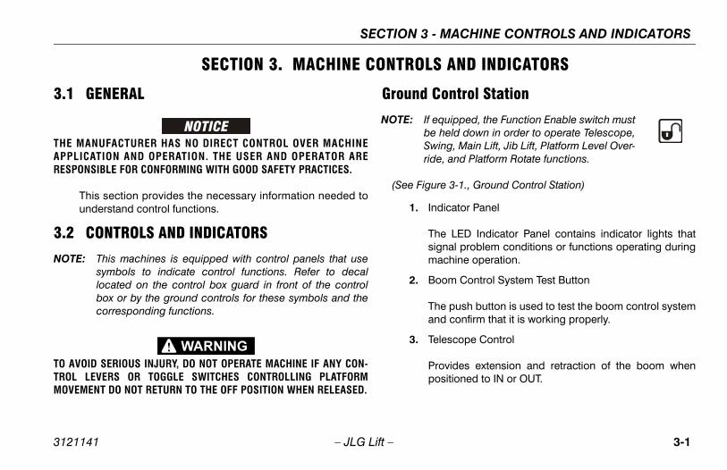
ontrol Station
quipped, the Function Enable switch must held down in order to operate Telescope,ing, Main Lift, Jib Lift, Platform Level Over-e, and Platform Rotate functions.
re 3-1., Ground Control Station)
dicator Panel
e LED Indicator Panel contains indicator lights thatgnal problem conditions or functions operating duringachine operation.
om Control System Test Button
e push button is used to test the boom control systemd confirm that it is working properly.
lescope Control
ovides extension and retraction of the boom whensitioned to IN or OUT.
SECTION 3 -
3121141 – JLG Lift –
SECTION 3. MACHINE CONTROLS
3.1 GENERAL
THE MANUFACTURER HAS NO DIRECT CONTROL OVER MACHINEAPPLICATION AND OPERATION. THE USER AND OPERATOR ARERESPONSIBLE FOR CONFORMING WITH GOOD SAFETY PRACTICES.
This section provides the necessary information needed tounderstand control functions.
3.2 CONTROLS AND INDICATORS
NOTE: This machines is equipped with control panels that usesymbols to indicate control functions. Refer to decallocated on the control box guard in front of the controlbox or by the ground controls for these symbols and thecorresponding functions.
TO AVOID SERIOUS INJURY, DO NOT OPERATE MACHINE IF ANY CON-TROL LEVERS OR TOGGLE SWITCHES CONTROLLING PLATFORMMOVEMENT DO NOT RETURN TO THE OFF POSITION WHEN RELEASED.
Ground C
NOTE: If ebeSwrid
(See Figu
1. In
Thsim
2. Bo
Than
3. Te
Prpo

SECTION 3 - MACHINE CONTROLS AND INDICATORS
3-2 3121141
on
1. Indicator Panel2. Boom Control System Test Button3. Telescope4. Swing5. Lift6. Platform/Ground Select Switch7. Hourmeter8. Power/Emergency Stop9. Engine Start/Auxiliary Power or Engine Start/Auxiliary Power/Function Enable10. Articulating Jib11. Platform Leveling Override12. Platform Rotate13. Jib Swing
– JLG Lift –
1706911 A
1 13
3
2
4 5 6
7
8
9
10
11
12
OR
Figure 3-1. Ground Control Stati

MACHINE CONTROLS AND INDICATORS
3-3
en Power/Emergency Stop switch is in the “ON” posi- and engine is not running, an alarm will sound, indi-
ting Ignition is “ON”.
ACHINE IS SHUT DOWN THE MASTER/EMERGENCY STOPST BE POSITIONED TO THE “OFF” POSITION TO PREVENTE BATTERY.
wer/Emergency Stop Switch
two-position red mushroom shaped switch furnisheswer to PLATFORM/GROUND SELECT switch whenlled out (on). When pushed in (off), power is shut off
the PLATFORM/GROUND SELECT switch.
SECTION 3 -
3121141 – JLG Lift –
4. Swing Control
Provides 360 degrees continuous turntable rotation.
5. Lift Control
Provides raising and lowering of the main boom.
NOTE: With PLATFORM/GROUND SELECT switch in the centerposition, power is shut off to controls at both operatingstations.
6. Platform/Ground Select Switch
A three position, key operated switch supplies power tothe platform control console when positioned to PLAT-FORM. With the switch key held in the GROUND posi-tion, power is shut off to platform and only groundcontrols are operable.
7. Hourmeter
Registers the amount of time the machine has been inuse, with engine running. By connecting into the oilpressure circuit of the engine, only engine run hours arerecorded. The hourmeter registers up to 9,999.9 hoursand cannot be reset.
NOTE: Whtionca
WHEN THE MSWITCH MUDRAINING TH
8. Po
A poputo

SECTION 3 - MACHINE CONTROLS AND INDICATORS
3-4 3121141
NOT
WHEFUNTHE
ating Jib
itch provides raising and lowering of the jib.
PLATFORM LEVELING OVERRIDE FUNCTION FOR OF THE PLATFORM. INCORRECT USE COULD CAUSEANTS TO SHIFT OR FALL. FAILURE TO DO SO COULD OR SERIOUS INJURY.
m Leveling Override
e position switch allows the operator to adjust theatic self leveling system. This switch is used to platform level in situations such as ascending/nding a grade.
m Rotate
position switch permits rotation of the platform.
tate
e position switch permits rotation of the jib andm.
– JLG Lift –
E: Auxiliary power only works if there is no engine oil pres-sure, and is disabled if engine is running.
Functions will operate at a slower than normal ratebecause of the lesser flow of hydraulic fluid delivered.
N USING AUXILIARY POWER, DO NOT OPERATE MORE THAN ONECTION AT A TIME. (SIMULTANEOUS OPERATION CAN OVERLOAD AUXILIARY PUMP.
9. Engine Start/Auxiliary Power Switch orEngine Start/ Auxiliary Power Switch /Function Enable
To start the engine, the switch must be held"UP" until the engine starts.
To use auxiliary power, the switch must beheld “DOWN” for duration of auxiliary pumpuse. Aux power can only be used if the engineis not running.
If equipped, the enable switch must be held"DOWN" to enable all boom controls when theengine is running.
10. Articul
This sw
ONLY USE THE SLIGHT LEVELINGTHE LOAD/OCCUPRESULT IN DEATH
11. Platfor
A threautomadjustdesce
12. Platfor
A three
13. Jib Ro
A threplatfor

MACHINE CONTROLS AND INDICATORS
3-5
w Engine Oil Pressure Indicator
dicates that engine oil pressure is below normal andrvice is required.
igh Engine Temperature Indicator
dicates that engine coolant temperature is abnormallygh and service is required.
gine Oil Temperature Indicator
dicates the temperature of the engine oil, which alsorves as engine coolant, is abnormally high and ser-
ce is required.
les Set Indicator
dicates that the axles are fully extended. The indicatorill flash as the axles are extending or retracting and be solid when fully extended. The light will go out when
e axles are fully retracted.
atform Capacity Indicator
dicates which capacity range is selected. This capac- can only be selected at the platform control console.
SECTION 3 -
3121141 – JLG Lift –
Ground Control Indicator Panel
(See Figure 3-2., Ground Control Indicator Panel)
1. Battery Charging Indicator
Indicates a problem in the battery or charging circuit,and service is required.
2. Lo
Inse
3. H
Inhi
4. En
Insevi
5. Ax
Inwonth
6. Pl
Inity
654321
789
1. Battery Charging2. Low Engine Oil Pressure3. High Engine Coolant Temp.4. High Engine Oil Temp.5. Axles Set
6. Platform Capacity7. Platform Overload 8. Boom Control System Warning9. Boom Control System Calibrated
Figure 3-2. Ground Control Indicator Panel

SECTION 3 - MACHINE CONTROLS AND INDICATORS
3-6 3121141
tion
3., Platform Control Console - Prior to S/N 79596,atform Control Console - S/N 79596 to 93078, andatform Control Console - w/Boom Control Select)
S INJURY, DO NOT OPERATE MACHINE IF ANY CON-R TOGGLE SWITCHES CONTROLLING PLATFORM
NOT RETURN TO THE OFF OR NEUTRAL POSITION.
/Emergency Stop
position red mushroom shaped switch furnishes to PLATFORM Controls when pulled out (on).pushed in (off), power is shut off to the platformns.
about 2 seconds of pulling the switch out, thene will perform a diagnostic check of the variouscal circuits, and if everything is OK, the platformwill beep once. During this time the lights on thetor panel will also blink once as a bulb check.
– JLG Lift –
7. Platform Overload Indicator (If Equipped)
Indicates the platform has been overloaded.
8. Boom Control System Warning Indicator
Indicates the platform is outside the operating area andoperation of certain boom functions may be disabled(i.e. lift, telescope). Attempts to use the disabled func-tions cause the indicator to flash and an alarm to sound.Immediately return the platform to the ground. If the indi-cator remains lit, a boom control system fault or failurehas been detected. If a failure is discovered, the systemmust be repaired by JLG authorized service personnelbefore the machine can be used.
9. Boom Control System Calibrated Indicator
When the Boom Control System Test Button is pushed,illuminates to indicate that the Boom Control System iscalibrated properly.
Platform Sta
(See Figure 3-Figure 3-4., PlFigure 3-5., Pl
TO AVOID SERIOUTROL LEVERS OMOVEMENT DO WHEN RELEASED
1. Power
A two-powerWhen functio
Withinmachielectrialarm indica

MACHINE CONTROLS AND INDICATORS
3-7
rive Orientation Override
hen the boom is swung over the rear tires or further inther direction, the Drive Orientation indicator will illumi-te when the drive function is selected. Push andlease the switch, and within 3 seconds move therive/Steer control to activate drive or steer. Before driv-g, locate the black/white orientation arrows on bothe chassis and the platform controls. Move the driventrols in a direction matching the directional arrows.
operate the Drive Joystick, pull up on the locking ringlow the handle.
e DRIVE control levers are spring-loaded and will auto-tically return to neutral (OFF) position when released.
rive/Steer
e DRIVE joystick provides for driving either forward orckward. The controller is ‘ramped’ to allow variableive speed.
eering is controlled by a thumb operated switch onp of the joystick.
SECTION 3 -
3121141 – JLG Lift –
2. Start/Auxiliary Power
When pushed forward, the switch energizes the startermotor to start the engine.
When pushed back, it energizes the electrically oper-ated hydraulic pump, when actuated. (Switch must beheld ON for duration of auxiliary pump use.)
The auxiliary pump functions to provide sufficient oil flowto operate the basic machine functions should the mainpump or engine fail. The auxiliary pump will operateplatform rotate, jib lift, jib swing, platform level override,main boom lift, main telescope and swing.
3. Capacity Select
This switch allows the operator to select between anoperating envelope with a 500 lb. (227 kg for ANSI mar-kets and 230 kg for CE and Australia markets) capacityrestriction or a 1000 lb. (454 kg for ANSI markets and450 kg for CE and Australia markets) capacity restric-tion.
4. D
WeinareDinthco
NOTE: To be
NOTE: Thma
5. D
Thbadr
Stto

SECTION 3 - MACHINE CONTROLS AND INDICATORS
3-8 3121141
567
2 3 4
w Overriden Speed Control
ift / Swingpeed / Torque Select
18. Steer Select19. Platform Level Override20. Horn21. Indicator Panel
S/N 79596
– JLG Lift –
1705175 A
1705171 A
17 18 19 20 21
9 8101314 12 111516
1
1. Power/Emergency Stop2. Engine Start / Aux Power3. Capacity Select4. Drive Orientation Override5. Drive/Steer
6. Telescope7. Lights8. Jib Lift9. Soft Touch Override
10. Jib Swing11. Axle Extend/Retract12. Soft Touch Indicator13. Platform Rotate
14. Jib Sto15. Functio16. Main L17. Drive S
Figure 3-3. Platform Control Console - Prior to

MACHINE CONTROLS AND INDICATORS
3-9
1705170 A
5678
1 2 3 4
ib Stow Overrideunction Speed Controlain Lift / Swingrive Speed / Torque Select
18. Steer Select19. Platform Level Override20. Horn21. Indicator Panel
79596 to 93078
SECTION 3 -
3121141 – JLG Lift –
1705744 A
1705745 B
17029381705171 A
17 18 19 20 21
9101314 12
11
1516
1. Power/Emergency Stop2. Engine Start / Aux Power3. Capacity Select4. Drive Orientation Override5. Drive/Steer
6. Telescope7. Lights8. Jib Lift9. Soft Touch Override
10. Jib Swing11. Axle Extend/Retract12. Soft Touch Indicator13. Platform Rotate
14. J15. F16. M17. D
Figure 3-4. Platform Control Console - S/N
SECTION 3 - MACHINE CONTROLS AND INDICATORS
3-1 3121141
567
2 3 4
n Speed Controlift / Swingpeed / Torque Selectelect
19. Platform Level Override20. Horn21. Indicator Panel22. Boom Control Select
ontrol Select
0 – JLG Lift –
1705744 A
1705745 B
1702938 1705170 A1705171 A
1706
741A
17 18 19 20 21
9 8101314 12
11
1516
122
1. Power/Emergency Stop2. Engine Start / Aux Power3. Capacity Select4. Drive Orientation Override5. Drive/Steer
6. Telescope7. Lights8. Jib Lift9. Soft Touch Override10. Jib Swing
11. Axle Extend/Retract12. Soft Touch Indicator13. Platform Rotate14. Jib Stow Override
15. Functio16. Main L17. Drive S18. Steer S
Figure 3-5. Platform Control Console - w/Boom C

MACHINE CONTROLS AND INDICATORS
3-11
e Jib Swing function is not operable when the Capacitylect control is in the 1000 lb. (454 kg for ANSI marketsd 450 kg for CE and Australia markets) position.
b Swing
is switch allows the operator to rotate the jib to the left right.
le Extend/Retract
is switch allows the operator to extend or retract theles. The axles can only be extended or retracted whilee machine is being driven forward or reverse.
ft Touch Indicator (If Equipped)
dicates the Soft Touch bumper is against an object. Allntrols are cut out until the override button is pushed,
which time controls are active in the Creep Mode.
atform Rotate
is switch allows the operator to rotate the basket toe left or right.
SECTION 3 -
3121141 – JLG Lift –
6. Main Telescope
This control allows extension and retraction of the mainboom.
7. Lights (If Equipped)
This switch operates accessory light packages if themachine is so equipped.
8. Jib Lift
Push forward to lift up, pull back to lift down. Variable liftspeed is using the Function Speed Control.
9. Soft Touch Override Switch (If equipped)
This switch enables the functions that were cut out bythe Soft Touch system to operate again at creep speed,allowing the operator to move the platform away fromthe obstacle that caused the shutdown situation.
NOTE: ThSean
10. Ji
Thor
11. Ax
Thaxth
12. So
Incoat
13. Pl
Thth

SECTION 3 - MACHINE CONTROLS AND INDICATORS
3-1 3121141
NOT
NOT
oom is positioned above transport position or tele- out and any of the following switches, DRIVE/TORQUE SELECT or FUNCTION SPEED, are posi-to HIGH, high function speeds are automatically and the machine continues to operate at a lower
E MACHINE IF DRIVE SPEED /TORQUE SELECT OR SWITCHES OPERATE WHEN BOOM IS MORE THANONTAL.
peed/Torque Select
rward position gives maximum drive speed by the drive motors to minimum displacement and
high engine when drive controller is moved. Theosition gives maximum torque for rough terrain
limbing grades by shifting the wheel motors toum displacement and giving high engine speeddrive controller is moved. The center position the machine to be driven as quietly as possibleving the engine at mid speed and the drive motorsimum displacement.
2 – JLG Lift –
14. Jib Stow Override
This switch allows the operator to rotate the jib to theright past the electronic stop to stow the jib under theboom for transport.
15. Function Speed Control
Controls the speed of Boom and Swing Functions.Rotate CCW for slower speed and CW for faster speed.To adjust to creep, turn knob fully CCW until it clicks.
E: To operate the Main Lift/Swing Joystick, pull up on thelocking ring below the handle.
E: The MAIN LIFT/SWING control lever is spring-loaded andwill automatically return to neutral (OFF) position whenreleased.
16. Main Lift/Swing Controller
An infinitely proportional dual axis joystick is providedfor main lift and swing. Push forward to lift up, pull back-ward to lift down. Move right to swing right, move left toswing left.
NOTE: When bscopedSPEEDtioned cut outspeed.
DO NOT OPERATFUNCTION SPEED15° ABOVE HORIZ
17. Drive S
The foshiftinggivingback pand cmaximwhen allowsby leain max

MACHINE CONTROLS AND INDICATORS
3-13
THE PLATFORM LEVELING OVERRIDE FUNCTION FORLING OF THE PLATFORM. INCORRECT USE COULD CAUSE
CCUPANTS TO SHIFT OR FALL. FAILURE TO DO SO COULDEATH OR SERIOUS INJURY.
atform Leveling Override
three position switch allows the operator to adjust thetomatic self leveling system. This switch is used tojust platform level in situations such as ascending/scending a grade.
orn
pressed, this switch supplies power to the horn.
SECTION 3 -
3121141 – JLG Lift –
18. Steer Select
When equipped with four wheel steering, the action ofthe steering system is operator selectable. The centerswitch position gives conventional front wheel steeringwith the rear wheels unaffected. This is for normal driv-ing at maximum speeds. The forward position is for“crab” steering. When in this mode both front and rearaxles steer in the same direction, which allows the chas-sis to move sideways as it goes forward. This can beused for positioning the machine in aisle ways or againstbuildings. The back switch position is for “coordinated”steering. In this mode the front and rear axles steer inthe opposite directions to produce the tightest turningcircle for maneuvering in confined areas.
ONLY USE SLIGHT LEVETHE LOAD/ORESULT IN D
19. Pl
A auadde
20. H
If

SECTION 3 - MACHINE CONTROLS AND INDICATORS
3-1 3121141
NOT
l Mode:
the boom control is positioned tol, lift and telescope movements arelled separately by the operator andtomatic platform leveling feature isonly during lift functions.
positioned to Manual, boom functions will be when the envelope limits are reached. When this
operate a different function or select the auto-osition.
ing upon the angle of the chassis and the angle ofm, swing left or swing right may be disallowed the Manual mode. The BCS light will illuminate
ther attempts to swing in the disallowed directionse the BCS to flash. When this occurs the only are to swing in the opposite direction or switch totic mode.
4 – JLG Lift –
21. Indicator Panel
The LED Indicator Panel contains indicator lights thatsignal problem conditions or functions operating duringmachine operation.
22. Boom Control Select
Automatic Mode:
When the Boom Control is positioned toAutomatic, lift and telescope movements arecoordinated by the JLG control system andthe automatic platform leveling feature isactive during lift, telescope, swing, and drive move-ments.
E: • While operating lift up, the boom may also telescopeout. • While operating lift down, the boom may also telescopein. • While operating swing or drive, the boom may lift up orlift down.• While operating telescope in, the boom may lift downwhen at high boom angles and the creep light is flashing.
Manua
WhenManuacontrothe auactive
NOTE: When stoppedoccurs,matic p
NOTE: Dependthe boowhile inand furwill cauchoicesautoma

MACHINE CONTROLS AND INDICATORS
3-15
nsport mode (24 inches [61 cm] 1200; 12 inches0.5 cm] 1350) or elevated more than 15° above hori-ntal.
EL SYSTEM FAULT INDICATOR IS ILLUMINATED, SHUTACHINE, RECYCLE THE EMERGENCY STOP, AND RESTARTE. IF THE FAULT PERSISTS, RETURN THE PLATFORM TO
D POSITION, USING MANUAL LEVELING AS REQUIRED,EVELING SYSTEM REPAIRED.
Generator
dicates the generator is in operation.
atform Overload Indicator (If Equipped)
dicates the platform has been overloaded.
atform Capacity Indicator
dicates the maximum platform capacity selected fore platform.
ne of the capacity lights should be on at all times. Bothhts will flash and an alarm will sound if the platform ist of the operating envelope for the selected capacity.
SECTION 3 -
3121141 – JLG Lift –
Platform Control Indicator Panel
(See Figure 3-6. or Figure 3-7.)
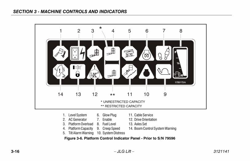
NOTE: The platform control indicator panel uses different shapedsymbols to alert the operator to different types of opera-tional situations that could arise. The meaning of thosesymbols are explained below.
1. Level System Fault Indicator
Indicates a fault in the electronic leveling system. Thefault indicator will flash and an alarm sound. All func-tions will default to creep if the boom is extended past
tra[3zo
IF THE LEVDOWN THE MTHE MACHINTHE STOWEAND HAVE L
2. AC
In
3. Pl
In
4. Pl
Inth
Oligou
Indicates a potentially hazardous situation, which ifnot corrected, could result in serious injury ordeath. This indicator will be red.
Indicates an abnormal operating condition, which ifnot corrected, may result in machine interruption ordamage. This indicator will be yellow.
Indicates important information regarding the oper-ating condition, i.e. procedures essential for safeoperation. This indicator will be green with theexception of the capacity indicator which will begreen or yellow depending upon platform position.
SECTION 3 - MACHINE CONTROLS AND INDICATORS
3-1 3121141
7 8
9
ceation
ol System Warning
r to S/N 79596
6 – JLG Lift –
1 2 3 4 5 6
1011121314
*
*** UNRESTRICTED CAPACITY** RESTRICTED CAPACITY
1. Level System2. AC Generator3. Platform Overload4. Platform Capacity5. Tilt Alarm Warning
6. Glow Plug7. Enable8. Fuel Level9. Creep Speed10. System Distress
11. Cable Servi12. Drive Orient13. Axles Set14. Boom Contr
Figure 3-6. Platform Control Indicator Panel - Prio

MACHINE CONTROLS AND INDICATORS
3-17
6 7 8
910Y
Servicerientation
Set Control System Warning
/N 79596 to Present
SECTION 3 -
3121141 – JLG Lift –
1 2 3 4 5
11121314
*
*** UNRESTRICTED CAPACIT** RESTRICTED CAPACITY
1. Level System2. AC Generator3. Platform Overload4. Platform Capacity5. Tilt Alarm Warning
6. Glow Plug7. Enable8. Fuel Level9. Creep Speed10. System Distress
11. Cable 12. Drive O13. Axles 14. Boom
Figure 3-7. Platform Control Indicator Panel - S

SECTION 3 - MACHINE CONTROLS AND INDICATORS
3-1 3121141
IF ILLOWIT IS15 d
itch/Enable Indicator
erate any function, the footswitch must besed and the function selected within seven sec-The enable indicator shows that the controls ared. If a function is not selected within seven sec-or if a seven second lapse between ending onen and beginning the next function, the enableill go out and the footswitch must be released andsed again to enable the controls.
ing the footswitch removes power from all con-nd applies the drive brakes.
US INJURY, DO NOT REMOVE, MODIFY OR DISABLE BY BLOCKING OR ANY OTHER MEANS.
ST BE ADJUSTED IF FUNCTIONS ACTIVATE WHENERATES WITHIN LAST 1/4" OF TRAVEL, TOP OR BOT-
8 – JLG Lift –
5. Tilt Alarm Warning Light and Alarm
Indicates that the chassis is on a slope. An alarm willalso sound when the chassis is on a slope and theboom is above transport position. If lit when the boom israised or extended, retract and lower to below horizontalthen re-position machine so that it is level before contin-uous operation. If the boom is above transport positionor telescoped, out and the machine is on a slope, the tiltalarm warning light will illuminate and an alarm willsound and CREEP is automatically activated.
LUMINATED WHEN BOOM IS RAISED OR EXTENDED, RETRACT ANDER TO BELOW HORIZONTAL THEN REPOSITION MACHINE SO THAT LEVEL BEFORE EXTENDING BOOM OR RAISING BOOM more thanegrees ABOVE HORIZONTAL.
6. Glow Plug Indicator
Indicates the glow plugs are operating. After turning onignition, wait until light goes out before cranking engine.
7. Footsw
To opdepresonds. enableonds, functiolight wdepres
Releastrols a
TO AVOID SERIOTHE FOOTSWITCH
FOOTSWITCH MUSWITCH ONLY OPTOM.
MACHINE CONTROLS AND INDICATORS
3-19
reep Speed Indicator
hen the Function Speed Control is turned to the creepsition, the indicator acts as a reminder that all func-ns are set to the slowest speed. The light flashes if thentrol system puts the machine into creep speed and
ill be on continuously if the operator selects creepeed.
stem Distress Indicator
e light indicates that the JLG Control System hastected a malfunction and a Diagnostic Trouble Codes been set in the system memory. Refer to the Service
anual for instructions concerning the trouble codesd trouble code retrieval.
e malfunction indicator light will illuminate for 2-3 sec-ds when the key is positioned to the on position to act a self test.
SECTION 3 -
3121141 – JLG Lift –
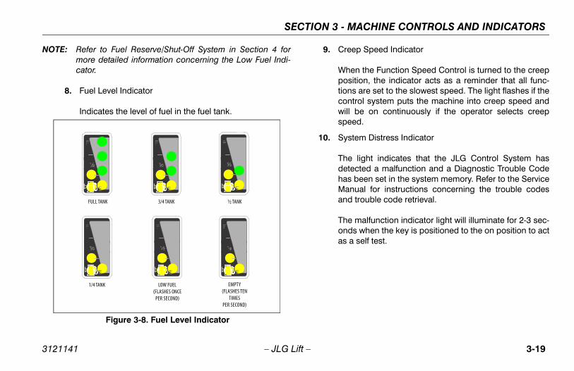
NOTE: Refer to Fuel Reserve/Shut-Off System in Section 4 formore detailed information concerning the Low Fuel Indi-cator.
8. Fuel Level Indicator
Indicates the level of fuel in the fuel tank.
9. C
Wpotiocowsp
10. Sy
ThdehaMan
Thonas
LOW FUEL(FLASHES ONCE
PER SECOND)
1/4 TANK
½ TANK3/4 TANKFULL TANK
EMPTY(FLASHES TEN
TIMESPER SECOND)
Figure 3-8. Fuel Level Indicator

SECTION 3 - MACHINE CONTROLS AND INDICATORS
3-2 3121141
Control System Warning Indicator
tes the platform is outside the operating area andion of certain boom functions may be disabledt, telescope). Attempts to use the disabled func-ause the indicator to flash and an alarm to sound.iately return the platform to the ground. If the indi-emains lit, a boom control system fault or failureen detected. If a failure is discovered, the systeme repaired by JLG authorized service personnel
the machine can be used.
0 – JLG Lift –
11. Cable Service Indicator
When illuminated, the light indicates the boom cablesare loose or broken and must be repaired or adjustedimmediately.
12. Drive Orientation Indicator
When the boom is swung beyond the rear drive tires orfurther in either direction, the Drive Orientation indicatorwill illuminate when the drive function is selected. This isa signal for the operator to verify that the drive control isbeing operated in the proper direction (i.e. controlsreversed situations).
13. Axles Set Indicator
Indicates that the axles are fully extended. The indicatorwill flash as the axles are extending or retracting and beon solid when fully extended. The light will go out whenthe axles are fully retracted.
14. Boom
Indicaoperat(i.e. liftions cImmedcator rhas bemust bbefore

SECTION 4 - MACHINE OPERATION
4-1
PERATION
OM OPERATING CHARACTERISTICS AND ITATIONS
esom can be raised more than 15° above horizontal without any load in platform, if:
achine is positioned on a smooth, firm and level sur-ce.
les are extended.
ad is within manufacturer’s rated capacity.
l machine systems are functioning properly.
oper tire pressure.
achine is as originally equipped from JLG.
3121141 – JLG Lift –
SECTION 4. MACHINE O
4.1 DESCRIPTIONThis machine is a self-propelled hydraulic lift equipped with awork platform on the end of an elevating and rotating boom.
The primary operator control station is in the platform. Fromthis control station, the operator can drive and steer themachine in both forward and reverse directions. The opera-tor can raise or lower the upper or lower boom or swing theboom to the left or right. Standard boom swing is 360 degreecontinuous left and right of the stowed position. The machinehas a Ground Control Station which will override the PlatformControl Station. Ground Controls operate Boom Lift andSwing, and are to be used in an emergency to lower the plat-form to the ground should the operator in the platform beunable to do so.
4.2 BOLIM
CapacitiThe boor with
1. Mfa
2. Ax
3. Lo
4. Al
5. Pr
6. M

SECTION 4 - MACHINE OPERATION
4-2 3121141
Co , telescope in will function automatically, or whenlescope out will function automatically.
Boom Control Switch is in the manual mode, liftope functions are independent functions con-
he operator.
– JLG Lift –
ntrolled Arc
When the Boom Control Select switch is in the automaticmode, the boom control system automatically controls liftand telescope when the lift function is selected to move theplatform through a predetermined arc, equivalent to the per-centage of extension. (i.e. If you start at 70% boom exten-sion, you will end up at approximately 70% boom extensionno matter where you stop in the arc). This means that when
lifting downlifting up, te
When the and telesctrolled by t

SECTION 4 - MACHINE OPERATION
4-3
om Control System in Automatic Mode: When theom is completely elevated along the edge of the back-rd stability region and the telescope in function is acti-ed, lift down will automatically function until the boomway from the edge of the backward stability region.
om Control System in Manual Mode: The boom willp when the end of the envelope is reached and theerator must activate lift and/or telescope in the properection to bring the boom back into the envelope.
d Anglentrol system automatically maintains a constant ele-
boom angle when swinging the turntable. If the boomis at 30 degrees, swing engaged by its self shall add liftntain the relative boom angle at 30 degrees.
eed Proportioningoom control system sensors sense the distance therm is extended from the turntable, allowing higherspeeds with the boom retracted and gradually slowerspeeds as the boom is extended.
3121141 – JLG Lift –
Envelope Tracking
When the platform approaches the edges of the operatingenvelope all machine functions are slowed down automati-cally by the boom control system to reduce machinemotions.
NOTE: Bobowavatis a
Bostoopdir
ControlleThe covated angle to mai
Swing SpThe bplatfoswing swing
BUFFER LINE
ENVELOPE
SLOWDOWN LINE
BUFFERZONE
SLOWDOWNZONE

SECTION 4 - MACHINE OPERATION
4-4 3121141
Sta
TO MAC
ITY SELECT
ntrol System allows the operator to select opera-. (227 kg for ANSI markets and 230 kg for CE andets) capacity restriction envelope or a 1000 lb.SI markets and 450 kg for CE and Australia mar- restriction envelope. The operator selects theity restriction by positioning the Capacity Select
platform console. The Capacity Indicator showselected, and both capacity lights will flash and an the platform is out of the selected capacity range.
on in the 1000 lb. (454 kg for ANSI markets and for CE and Australia markets) envelope requireso be fixed in the centered position.
– JLG Lift –
bilityMachine stability is based on two (2) conditions which arecalled FORWARD and BACKWARD stability. The machine’sposition of least FORWARD stability is shown in (See Figure4-1.), and its position of least BACKWARD stability is shownin (See Figure 4-2.)
AVOID FORWARD OR BACKWARD TIPPING, DO NOT OVERLOADHINE OR OPERATE THE MACHINE ON AN OUT-OF-LEVEL SURFACE.
4.3 CAPAC
The Boom Cotion in a 500 lbAustralia mark(454 kg for ANkets) capacitydesired capacswitch on thethe capacity salarm sound if
NOTE: Operati450 kgthe jib t

SECTION 4 - MACHINE OPERATION
4-5
rn SELECT switch to PLATFORM.
om Platform, pull POWER/EMERGENCY STOP switch t, then push the ENGINE START switch until engine
arts.
otswitch must be in released (up) position beforerter will operate. If starter operates with footswitch in depressed position, DO NOT OPERATE MACHINE.
n Procedure
E MALFUNCTION CAUSES AN UNSCHEDULED SHUTDOWN,THE CAUSE AND CORRECT IT BEFORE RESTARTING THE
move all load and allow engine to operate at loweed for 3-5 minutes; this allows further reduction of
ternal engine temperature.
sh POWER/EMERGENCY STOP switch in.
rn MASTER switch to Off.
to Engine Manufacturer’s manual for detailed informa-
3121141 – JLG Lift –
4.4 ENGINE OPERATION
NOTE: Initial starting should always be performed from theGround Control station.
Starting Procedure
IF ENGINE FAILS TO START PROMPTLY, DO NOT CRANK FOR ANEXTENDED TIME. SHOULD ENGINE FAIL TO START AGAIN, ALLOWSTARTER TO “COOL OFF” FOR 2-3 MINUTES. IF ENGINE FAILS AFTERSEVERAL ATTEMPTS, REFER TO ENGINE MAINTENANCE MANUAL.
NOTE: Diesel engines only: After turning on ignition, operatormust wait until glow plug indicator light goes out beforecranking engine.
1. Turn key of SELECT switch to GROUND. PositionPOWER/EMERGENCY STOP switch to ON, then pushthe ENGINE START switch until engine starts.
ALLOW ENGINE TO WARM-UP FOR A FEW MINUTES AT LOW SPEEDBEFORE APPLYING ANY LOAD.
2. After engine has had sufficient time to warm up, shut engine off.
3. Tu
4. Froust
NOTE: Fostathe
Shutdow
IF AN ENGINDETERMINE ENGINE.
1. Respin
2. Pu
3. Tu
Refer tion.

SECTION 4 - MACHINE OPERATION
4-6 3121141
Fue
NOT
e Restart - When the engine shuts down, the opera-ill be permitted to cycle power and restart the engine
pproximately 2 minutes of run time. After the 2 min-of run time is complete, the operator may cycle powerrestart the engine for an additional 2 minutes of run. The operator can repeat this process until there is no fuel available.
LIFIED JLG MECHANIC IF THE MACHINE NEEDSR NO MORE FUEL IS AVAILABLE.
e Stop - The engine will shut down. No restarts willrmitted until fuel is added to the tank.
– JLG Lift –
l Reserve / Shut-Off System
E: Reference the Service and Maintenance Manual along with aqualified JLG Mechanic to verify your machine setup.
The Fuel Shutoff System monitors the fuel in the tank and senseswhen the fuel level is getting low. The JLG Control System auto-matically shuts the engine down before the fuel tank is emptiedunless the machine is set up for Engine Restart.
If fuel level reaches the Low Fuel range the ¼ tankindicator will flash once a second and there will beapproximately 5 minutes of engine run time left. Ifthe system is in this condition and automaticallyshuts down the engine, or the engine is manuallyshut down before the 5 minute run time is com-plete, the ¼ tank indicator will flash 10 times a sec-ond and the engine will react according tomachine setup. Setup options are as follows:
• Engine One Restart - When the engine shuts down, theoperator will be permitted to cycle power and restart theengine once with approximately 2 minutes of run time.After the 2 minute run time is complete or if the engine isshut down by the operator prior to the completion of the 2minute run time, it cannot be restarted until fuel is addedto the tank.
• Engintor wfor autes and timemore
CONTACT A QUARESTARTED AFTE
• Enginbe pe

SECTION 4 - MACHINE OPERATION
4-7
rd Stability
3121141 – JLG Lift –
Figure 4-1. Position of Least Forwa

SECTION 4 - MACHINE OPERATION
4-8 3121141
. LING (DRIVING)
e upper boom is raised approximately 15 degreesorizontal, the high drive function will automaticallyw drive.
WITH BOOM ABOVE HORIZONTAL EXCEPT ON AND LEVEL SURFACE.
F TRAVEL CONTROL OR “TIP OVER”, DO NOT DRIVEADES EXCEEDING THOSE SPECIFIED ON THE SERIAL
SIDESLOPES WHICH EXCEED 5 DEGREES.
AUTION WHEN DRIVING IN REVERSE AND AT ALL PLATFORM IS ELEVATED.
– JLG Lift –
4.5 TRAVE
NOTE: When thabove hbe in lo
DO NOT DRIVE SMOOTH, FIRM A
TO AVOID LOSS OMACHINE ON GRNUMBER PLATE.
DO NOT DRIVE ON
USE EXTREME CTIMES WHEN THE
Figure 4-2. Position of Least Backward Stability

SECTION 4 - MACHINE OPERATION
4-9
atch the black and white direction arrows on both plat-rm control panel and the chassis to determine the rection the machine will travel.
sh and release the Drive Orientation Override switch. ithin 3 seconds, slowly move the Drive control toward e arrow matching the intended direction of machine vel. The indicator light will flash during the 3 second
terval until the drive function is selected.
ERINGn thumb switch on Drive/Steer controller to RIGHT forg right, or to LEFT for steering left.
TENDING THE AXLES
e operator must be driving the machine (forward orerse) in order to extend the axles.
n the Axle Extend switch to extend the axles or to to retract the axles.
3121141 – JLG Lift –
BEFORE DRIVING, LOCATE THE BLACK/WHITE ORIENTATION ARROWSON BOTH THE CHASSIS AND THE PLATFORM CONTROLS. MOVE THEDRIVE CONTROLS IN A DIRECTION MATCHING THE DIRECTIONALARROWS.
Traveling Forward and Reverse1. At Platform Controls, pull out Emergency Stop switch,
start engine, and activate footswitch.
2. Position Drive controller to FORWARD or REVERSE as desired.
This machine is equipped with a Drive Orientation Indicator.The yellow light on the platform control console indicatesthat the boom is swung beyond the rear drive tires and themachine may Drive/Steer in the opposite direction from themovement of the controls. If the indicator is illuminated,operate the Drive function in the following manner:
1. Mfodi
2. PuWthtrain
4.6 STEPositiosteerin
4.7 EX
NOTE: Threv
Positioretract

SECTION 4 - MACHINE OPERATION
4-1 3121141
s
0 – JLG Lift –
Figure 4-3. Grade and Side Slope

SECTION 4 - MACHINE OPERATION
4-11
Rotationate the platform to the left or right, use the Platform control switch to select the direction and hold until
d position is reached.
OM
NG OR RAISE BOOM ABOVE HORIZONTAL WHEN MACHINEVEL.
END ON TILT ALARM AS A LEVEL INDICATOR FOR THE
IP OVER, LOWER PLATFORM TO GROUND LEVEL. THENINE TO A LEVEL SURFACE BEFORE RAISING BOOM.
RIOUS INJURY, DO NOT OPERATE MACHINE IF ANY CON- OR TOGGLE SWITCH CONTROLLING PLATFORM MOVE-NOT RETURN TO THE ‘OFF’ OR NEUTRAL POSITION WHEN
FORM DOES NOT STOP WHEN A CONTROL SWITCH ORELEASED, REMOVE FOOT FROM FOOTSWITCH OR USE STOP SWITCH TO STOP THE MACHINE.
3121141 – JLG Lift –
4.8 PLATFORM
Platform Level Adjustment
ONLY USE THE PLATFORM LEVELING OVERRIDE FUNCTION FORSLIGHT LEVELING OF THE PLATFORM. INCORRECT USE COULD CAUSETHE LOAD/OCCUPANTS TO SHIFT OR FALL. FAILURE TO DO SO COULDRESULT IN DEATH OR SERIOUS INJURY.
NOTE: When the Boom Control Select Switch is in the Manualmode, Platform leveling only functions during Main Liftoperation. When the Boom Control Select Switch is in theAutomatic mode, Platform Leveling is active during allfunctions except during telescope operation. Also, whenin the Manual mode, the Controlled Angle system is notactive.
During normal operation of the machine, the platform willautomatically maintain it’s position. To manually Level Up orDown - Position the Platform/Level control switch Up orDown and hold until the desired platform position isobtained.
PlatformTo rotRotatedesire
4.9 BO
DO NOT SWIIS OUT OF LE
DO NOT DEPCHASSIS.
TO AVOID TDRIVE MACH
TO AVOID SETROL LEVERMENT DOES RELEASED.
IF THE PLATLEVER IS REMERGENCY

SECTION 4 - MACHINE OPERATION
4-1 3121141
Sw
WHETHEMEN
Ra
NOT
Tel
NOT
ToS
e Jib
0 lb. (454 kg for ANSI markets and 450 kg for CEstralia markets) mode operation, the jib must bed and the Jib Swing function is not operable. If thet of the centered position when in this mode, theg function will allow the operator to center the jib
e jib, use the Jib Swing control to select Right orn.
ION SPEED CONTROLl affects the speed of all boom functions and Plat-e. When in the CCW maximum position, Drive isreep speed.
2 – JLG Lift –
inging the BoomTo swing boom, use Swing control to select Right or Leftdirection.
N SWINGING THE BOOM MAKE SURE THERE IS AMPLE ROOM FOR BOOM TO CLEAR SURROUNDING WALLS, PARTITIONS AND EQUIP-T.
ising and Lowering the Boom
E: The lift function is not operable above 15 degrees abovehorizontal if the axles are not fully extended.
To raise or lower the Boom, use Boom Lift control to selectUp or Down movement.
escoping the Boom
E: The telescope function is not operable beyond the trans-port position if the axles are not fully extended.
extend or retract the main boom, use the Telescope Controlwitch to select In or Out movement.
Swinging th
NOTE: For 100and Aucenterejib is oujib swinagain.
To swing thLeft directio
4.10 FUNCTThis controform Rotatplaced in c

SECTION 4 - MACHINE OPERATION
4-13
isconnect drive hubs by inverting disconnect cap.
connect the drive hubs by inverting the disconnect p when towing is complete.
Figure 4-4. Drive Disconnect Hub
3121141 – JLG Lift –
4.11 EMERGENCY TOWING
RUNAWAY VEHICLE/MACHINE HAZARD. MACHINE HAS NO TOWINGBRAKES. TOWING VEHICLE MUST BE ABLE TO CONTROL MACHINE ATALL TIMES. ON-HIGHWAY TOWING NOT PERMITTED. FAILURE TO FOL-LOW INSTRUCTIONS COULD CAUSE SERIOUS INJURY OR DEATH.
MAXIMUM TOWING SPEED 5 M.P.H. (8 K.M.H.)
MAXIMUM TOWING GRADE 25%.
DO NOT TOW MACHINE WITH ENGINE OPERATING OR DRIVE HUBSENGAGED.
1. Retract, lower and position boom in travel position; lockturntable.
2. D
3. Reca

SECTION 4 - MACHINE OPERATION
4-1 3121141
4.1 G AND TIE DOWN
. and Figure 4-6.
G Industries or weigh the individual unit to find Gross Vehicle Weight.
the boom in the stowed position with the turntable .
e all loose items from the machine.
lifting device and equipment only to the desig-lifting points.
rly adjust the rigging to prevent damage to the ne and so the machine remains level.
4 – JLG Lift –
2 SHUT DOWN AND PARKTo shut down and park the machine, the procedures are asfollows:
1. Drive machine to a reasonably well protected area.
2. Ensure boom is lowered over rear drive axle.
3. Push in the Emergency Stop at Platform Controls.
4. Push in the Emergency Stop at Ground Controls. Posi-tion Platform/Ground Select switch to center OFF.
5. If necessary, cover Platform Controls to protect instruc-tion placards, warning decals and operating controls from hostile environment.
4.13 LIFTIN
See Figure 4-5
Lifting1. Call JL
out the
2. Place locked
3. Remov
4. Attachnated
5. Propemachi

SECTION 4 - MACHINE OPERATION
4-15
WING THE JIB FOR TRANSPORTace the boom in the stowed position with the axlestracted.
old the Jib Swing control switch to the right until the atform will no longer swing.
e Jib Swing function is not operable when the Capacitylect control is in the 1000 lb. (454 kg for ANSI marketsd 450 kg for CE and Australia markets) position.
tomatic platform leveling is disabled when stowing the
sh and hold the Jib Stow control switch until the jib d platform are in the stowed position under the boom.
3121141 – JLG Lift –
Tie Down
WHEN TRANSPORTING THE MACHINE, THE BOOM MUST BE FULLYLOWERED INTO THE BOOM REST.
NOTE: Prior to loading the machine onto a trailer, it will be neces-sary to rotate the turntable 180 degrees to provide betterweight distribution.
1. Place the boom in the stowed position with the turntablelocked.
2. Remove all loose items from the machine.
3. Secure the chassis and the platform using straps or chains of adequate strength and attached to the desig-nated tie down points.
4.14 STO1. Pl
re
2. Hpl
NOTE: ThSean
NOTE: Aujib.
3. Puan

SECTION 4 - MACHINE OPERATION
4-1 3121141
et 1 of 2
6 – JLG Lift –
Figure 4-5. Lifting and Tie Down Chart - She

SECTION 4 - MACHINE OPERATION
4-17
Sheet 2 of 2
3121141 – JLG Lift –
Figure 4-6. Lifting and Tie Down Chart -

SECTION 4 - MACHINE OPERATION
4-1 3121141
5
8 – JLG Lift –
Figure 4-7. Decal Location Sheet 1 of

SECTION 4 - MACHINE OPERATION
4-19
of 5
3121141 – JLG Lift –
Figure 4-8. Decal Location Sheet 2

SECTION 4 - MACHINE OPERATION
4-2 3121141
of 5
0 – JLG Lift –
Figure 4-9. Decal Location Sheet 3

SECTION 4 - MACHINE OPERATION
4-21
eet 4 of 5
3121141 – JLG Lift –
Figure 4-10. Decal Location Sh

SECTION 4 - MACHINE OPERATION
4-2 3121141
f 5
2 – JLG Lift –
Figure 4-11. Decal Location Sheet 5 o

SECTION 4 - MACHINE OPERATION
4-23
0300141473
sh/ish26-8
French/English
0274727-7
CE/Australian0274728-8
Japan0274729-7
- - - - - -
499 1701499 1701499 1701499
- - - - - -
- - - - - -
509 1701509 1701509 1701509
529 1701529 1701529 1701529
811 1703811 1703811 1703811
814 1703814 1703814 1703814
277 1704277 1704277 1704277
412 1704412 1704412 1704412
- - 17055515 - -
1705514 - - - -
243 3251243 - - 3251243
- - - - - -
337 1705341 - - 1705338
916 1705505 - - 1705493
3121141 – JLG Lift –
Table 4-1. Decal Legend - Prior to S/N
Item # ANSI0274722-7
Korean0274723-7
Chinese0274724-7
Portuguese0274725-7
EngliSpan
02747
1 - - - - - - - - - -
2 1701499 1701499 1701499 1701499 1701
3 - - - - - - - - - -
4 - - - - - - - - - -
5 1701509 1701509 1701509 1701509 1701
6 1701529 1701529 1701529 1701529 1701
7 1703811 1703811 1703811 1703811 1703
8 1703814 1703814 1703814 1703814 1703
9 1704277 1704277 1704277 1704277 1704
10 1704412 1704412 1704412 1704412 1704
11 - - - - - - - - - -
12 - - - - - - - - - -
13 3251243 3251243 3251243 3251243 3251
14 - - - - - - - - - -
15 1705337 1705337 1705342 1705904 1705
16 - - - - 1705507 1705906 1705

SECTION 4 - MACHINE OPERATION
4-2 3121141
1704006 - - - -
1703942 - - 1703944
1704000 - - - -
1703924 1705921 1703926
1705347 1705822 1705344
1703948 1701518 1703950
1703936 1705961 1703938
1703984 1705828 1703980
3251813 - - 3251813
1705506 - - 1705494
1702631 1702631 1702631
1705333 1706770 1705330
1705477 1705468 1705480
1700584 1700584 1700584
1706751 - - 1706751
1705868 - - 1705868
1705429 - - 1705426
1701505 1701505 1701505
0141473
French/English
0274727-7
CE/Australian0274728-8
Japan0274729-7
4 – JLG Lift –
17 - - 1702153 - - 1705901 1704007
18 1703953 1703953 1703943 1705903 1703941
19 1702868 1702868 1705968 1705967 1704001
20 1703797 1703797 1703925 1705895 1703923
21 1705336 1705336 1705348 1705896 1705917
22 1703804 1703804 1703949 1705898 1703947
23 1703805 1703805 1703937 1705897 1703935
24 3252347 - - 1703982 1705902 1703983
25 3251813 3251813 3251813 3251813 3251813
26 1705492 1705492 1705508 1705907 1705915
27 1702631 1702631 1702631 1702631 1702631
28 1705168 1705168 1705334 1705899 1705908
29 1705181 1705181 1705478 1705900 1705919
30 1700584 1700584 1700584 1700584 1700584
31 1706751 1706751 1706751 1706751 1706751
32 1705868 1705868 1705868 1705868 1705868
33 1705351 1705351 1705430 1705905 1705910
34 1701505 1701505 1701505 1701505 1701505
Table 4-1. Decal Legend - Prior to S/N 030
Item # ANSI0274722-7
Korean0274723-7
Chinese0274724-7
Portuguese0274725-7
English/Spanish
0274726-8

SECTION 4 - MACHINE OPERATION
4-25
063 1706064 1706098 1704972
511 1705511 1705511 1705511
501 1701501 1701501 1701501
- - - - - -
- - - - - -
- - - - - -
- - - - - -
- - - - - -
- - - - - -
- - - - - -
- - - - - -
- - - - - -
- - - - - -
- - - - - -
- - - - - -
- - - - - -
- - - - - -
- - - - - -
0300141473
sh/ish26-8
French/English
0274727-7
CE/Australian0274728-8
Japan0274729-7
3121141 – JLG Lift –
35 1704972 1704972 1706060 1706059 1706
36 1705511 1705511 1705511 1705511 1705
37 1701501 1701501 1701501 1701501 1701
38 - - - - - - - - - -
39 - - - - - - - - - -
40 - - - - - - - - - -
41 - - - - - - - - - -
42 - - - - - - - - - -
43 - - - - - - - - - -
44 - - - - - - - - - -
45 - - - - - - - - - -
46 - - - - - - - - - -
47 - - - - - - - - - -
48 - - - - - - - - - -
49 - - - - - - - - - -
50 - - - - - - - - - -
51 - - - - - - - - - -
52 - - - - - - - - - -
Table 4-1. Decal Legend - Prior to S/N
Item # ANSI0274722-7
Korean0274723-7
Chinese0274724-7
Portuguese0274725-7
EngliSpan
02747

SECTION 4 - MACHINE OPERATION
4-2 3121141
- - - - - -
- - - - - -
- - - - - -
- - - - - -
- - - - - -
- - - - - -
- - - - - -
- - - - - -
0141473
French/English
0274727-7
CE/Australian0274728-8
Japan0274729-7
6 – JLG Lift –
53 - - - - - - - - - -
54 - - - - - - - - - -
55 - - - - - - - - - -
56 - - - - - - - - - -
57 - - - - - - - - - -
58 - - - - - - - - - -
59 - - - - - - - - - -
60 - - - - - - - - - -
Table 4-1. Decal Legend - Prior to S/N 030
Item # ANSI0274722-7
Korean0274723-7
Chinese0274724-7
Portuguese0274725-7
English/Spanish
0274726-8

SECTION 4 - MACHINE OPERATION
4-27
73 to Present
sh/ish26-9
French/English
0274727-8
CE/Australian0274728-8
Japan0274729-8
- - - - - -
499 1701499 1701499 1701499
- - - - - -
- - - - - -
509 1701509 1701509 1701509
529 1701529 1701529 1701529
811 1703811 1703811 1703811
814 1703814 1703814 1703814
277 1704277 1704277 1704277
412 1704412 1704412 1704412
- - 17055515 - -
1705514 - - - -
243 3251243 - - 3251243
- - - - - -
337 1705341 - - 1705338
916 1705505 - - 1705493
3121141 – JLG Lift –
Table 4-2. Decal Legend - S/N 03001414
Item # ANSI0274722-8
Korean0274723-8
Chinese0274724-8
Portuguese0274725-8
EngliSpan
02747
1 - - - - - - - - - -
2 1701499 1701499 1701499 1701499 1701
3 - - - - - - - - - -
4 - - - - - - - - - -
5 1701509 1701509 1701509 1701509 1701
6 1701529 1701529 1701529 1701529 1701
7 1703811 1703811 1703811 1703811 1703
8 1703814 1703814 1703814 1703814 1703
9 1704277 1704277 1704277 1704277 1704
10 1704412 1704412 1704412 1704412 1704
11 - - - - - - - - - -
12 - - - - - - - - - -
13 3251243 3251243 3251243 3251243 3251
14 - - - - - - - - - -
15 1705337 1705337 1705342 1705904 1705
16 - - - - 1705507 1705906 1705

SECTION 4 - MACHINE OPERATION
4-2 3121141
1704006 - - - -
1703942 - - 1703944
1704000 - - - -
1703924 1705921 1703926
1705347 1705822 1705344
1703948 1701518 1703950
1703936 1705961 1703938
1703984 1705828 1703980
3251813 - - 3251813
1705506 - - 1705494
1702631 1702631 1702631
1001122374 1706770 1001122375
1001122381 1705468 1001122382
1700584 1700584 1700584
1706751 - - 1706751
1705868 - - 1705868
1705429 - - 1705426
1701505 1701505 1701505
o Present
French/English
0274727-8
CE/Australian0274728-8
Japan0274729-8
8 – JLG Lift –
17 - - 1702153 - - 1705901 1704007
18 1703953 1703953 1703943 1705903 1703941
19 1702868 1702868 1705968 1705967 1704001
20 1703797 1703797 1703925 1705895 1703923
21 1705336 1705336 1705348 1705896 1705917
22 1703804 1703804 1703949 1705898 1703947
23 1703805 1703805 1703937 1705897 1703935
24 3252347 - - 1703982 1705902 1703983
25 3251813 3251813 3251813 3251813 3251813
26 1705492 1705492 1705508 1705907 1705915
27 1702631 1702631 1702631 1702631 1702631
28 1001122369 1001122370 1001122371 1001122372 1001122373
29 1001122376 1001122377 1001122378 1001122379 1001122380
30 1700584 1700584 1700584 1700584 1700584
31 1706751 1706751 1706751 1706751 1706751
32 1705868 1705868 1705868 1705868 1705868
33 1705351 1705351 1705430 1705905 1705910
34 1701505 1701505 1701505 1701505 1701505
Table 4-2. Decal Legend - S/N 0300141473 t
Item # ANSI0274722-8
Korean0274723-8
Chinese0274724-8
Portuguese0274725-8
English/Spanish
0274726-9

SECTION 4 - MACHINE OPERATION
4-29
063 1706064 1706098 1704972
511 1705511 1705511 1705511
501 1701501 1701501 1701501
- - - - - -
- - - - - -
- - - - - -
- - - - - -
- - - - - -
- - - - - -
- - - - - -
- - - - - -
- - - - - -
- - - - - -
- - - - - -
- - - - - -
- - - - - -
- - - - - -
- - - - - -
73 to Present
sh/ish26-9
French/English
0274727-8
CE/Australian0274728-8
Japan0274729-8
3121141 – JLG Lift –
35 1704972 1704972 1706060 1706059 1706
36 1705511 1705511 1705511 1705511 1705
37 1701501 1701501 1701501 1701501 1701
38 - - - - - - - - - -
39 - - - - - - - - - -
40 - - - - - - - - - -
41 - - - - - - - - - -
42 - - - - - - - - - -
43 - - - - - - - - - -
44 - - - - - - - - - -
45 - - - - - - - - - -
46 - - - - - - - - - -
47 - - - - - - - - - -
48 - - - - - - - - - -
49 - - - - - - - - - -
50 - - - - - - - - - -
51 - - - - - - - - - -
52 - - - - - - - - - -
Table 4-2. Decal Legend - S/N 03001414
Item # ANSI0274722-8
Korean0274723-8
Chinese0274724-8
Portuguese0274725-8
EngliSpan
02747

SECTION 4 - MACHINE OPERATION
4-3 3121141
- - - - - -
- - - - - -
- - - - - -
- - - - - -
- - - - - -
- - - - - -
- - - - - -
- - - - - -
o Present
French/English
0274727-8
CE/Australian0274728-8
Japan0274729-8
0 – JLG Lift –
53 - - - - - - - - - -
54 - - - - - - - - - -
55 - - - - - - - - - -
56 - - - - - - - - - -
57 - - - - - - - - - -
58 - - - - - - - - - -
59 - - - - - - - - - -
60 - - - - - - - - - -
Table 4-2. Decal Legend - S/N 0300141473 t
Item # ANSI0274722-8
Korean0274723-8
Chinese0274724-8
Portuguese0274725-8
English/Spanish
0274726-9

SECTION 5 - EMERGENCY PROCEDURES
5-1
ROCEDURES
ANY ACCIDENT, THOROUGHLY INSPECT THE MACHINELL FUNCTIONS FIRST FROM THE GROUND CONTROLS,THE PLATFORM CONTROLS. DO NOT LIFT ABOVE 3 M (10OU ARE SURE THAT ALL DAMAGE HAS BEEN REPAIRED, IFND THAT ALL CONTROLS ARE OPERATING CORRECTLY.
ERGENCY OPERATION
Unable to Control Machine PLATFORM OPERATOR IS PINNED, TRAPPED OR
LE TO OPERATE OR CONTROL MACHINE:
ther personnel should operate the machine from ound controls only as required.
ther qualified personnel on the platform may use the atform controls. DO NOT CONTINUE OPERATION IF ONTROLS DO NOT FUNCTION PROPERLY.
ranes, forklift trucks or other equipment can be used to move platform occupants and stabilize motion of the achine.
3121141 – JLG Lift –
SECTION 5. EMERGENCY P
5.1 GENERALThis section explains the steps to be taken in case of anemergency situation while operating.
5.2 INCIDENT NOTIFICATIONJLG Industries, Inc. must be notified immediately of any inci-dent involving a JLG product. Even if no injury or propertydamage is evident, the factory should be contacted by tele-phone and provided with all necessary details.
In USA:JLG Phone: 877-JLG-SAFE (554-7233) (8am till 4:45pm EST)
Outside USA: 240-420-2661
E-mail:
Failure to notify the manufacturer of an incident involving aJLG Industries product within 48 hours of such an occur-rence may void any warranty consideration on that particularmachine.
FOLLOWINGAND TEST ATHEN FROM FT.) UNTIL YREQUIRED, A
5.3 EM
OperatorIF THEUNAB
1. Ogr
2. OplC
3. Crem

SECTION 5 - EMERGENCY PROCEDURES
5-2 3121141
Pla
BoSys
GENCY TOWING PROCEDURES machine is prohibited, unless properly equipped.provisions for moving the machine have beend. For specific procedures, refer to Section 4.
– JLG Lift –
tform or Boom Caught OverheadIf the platform or boom becomes jammed or snagged inoverhead structures or equipment, rescue platform occu-pants prior to freeing the machine.
om Movement Prevented By Boom Control temLowering the boom onto an object or structure, with theboom at high angles, may cause the boom control system toprevent movement of the machine. This can include move-ment necessary to lift the boom off the object. Movement ofthe boom can be regained by observing the following:
1. Shut off the engine.
2. Rescue platform occupants prior to freeing machine.
3. Use cranes, forklifts or other equipment to stabilize motion of the machine as required.
4. From the ground control position, use the Auxiliary Power System to carefully raise the boom off the object.
5. Once clear, restart the engine and return the platform to the ground.
6. Inspect the machine for damage before continued use of the machine.
5.4 EMERTowing thisHowever, incorporate

FICATIONS & OPERATOR MAINTENANCE
6-1
OPERATOR MAINTENANCE
ERATING SPECIFICATIONS
Operating Specifications - Prior to S/N 0300141473
ork Load (Capacity)d 500 lb (230 kg)
1000 lb. (450 kg)
Platform Height (Unrestricted)120 ft. (36.6 m)135 ft. (41.2 m)
Platform Height (Restricted)115 ft. (35.1 m)125 ft. (38.1 m)
tal Platform Reach (Unrestricted)75 ft. (22.9 m)80 ft. (24.4 m)
tal Platform Reach (Restricted)65 ft. (19.8 m)70 ft. (21.3 m)
Motiontion
8ft. (2.44m)180° working, 244° stowed130° (+75/-55)
SECTION 6 - GENERAL SPECI
3121141 – JLG Lift –
SECTION 6. GENERAL SPECIFICATIONS &
6.1 INTRODUCTIONThis section of the manual provides additional necessaryinformation to the operator for proper operation and mainte-nance of this machine.
The maintenance portion of this section is intended as infor-mation to assist the machine operator to perform daily main-tenance tasks only, and does not replace the more thoroughPreventive Maintenance and Inspection Schedule includedin the Service and Maintenance Manual.
Other Publications Available:
Service and Maintenance Manual ............................ 3121142
Illustrated Parts Manual ............................................ 3121208
6.2 OP
Table 6-1.
Maximum W Unrestricte Restricted
Max.Vertical 1200SJP 1350SJP
Max.Vertical 1200SJP 1350SJP
Max.Horizon 1200SJP 1350SJP
Max.Horizon 1200SJP 1350SJP
JibPLUS Length Horizontal Vertical Mo

SECTION 6 - GENERAL SPECIFICATIONS & OPERATOR MAINTENANCE
6-2 3121141
DataT
Ma U R
MaCE U R
Ma 1 1
Ma 1 1
Ma 1 1
Ma 1 1
Jib L H V
Table 6-3. Dimensional Data
8ft. 2in. (2.49 m)12ft. 6in. (3.8 m)
10ft. (3.04 m)
nsport Mode)34ft. 11in. (10.64 m)38ft. 11in. (11.86 m)
orking Mode)44ft. 11in. (13.69 m)48ft. 11in. (14.91 m)
12ft. 6in. (3.81 m)
5ft. 6 in. (1.6 m)
(Axle) 12 in. (30.4 cm)
(Chassis) 25.5 in. (64.7 cm)
– JLG Lift –
Dimensionalable 6-2. Operating Specifications - S/N 0300141473 to Present
ximum Work Load (Capacity) - ANSInrestrictedestricted
500 lb (227 kg)1000 lb. (454 kg)
ximum Work Load (Capacity)- & Australianrestrictedestricted
500 lb (230 kg)1000 lb. (450 kg)
x.Vertical Platform Height (Unrestricted)200SJP 350SJP
120 ft. (36.6 m)135 ft. (41.2 m)
x.Vertical Platform Height (Restricted)200SJP350SJP
115 ft. (35.1 m)125 ft. (38.1 m)
x.Horizontal Platform Reach (Unrestricted)200SJP350SJP
75 ft. (22.9 m)80 ft. (24.4 m)
x.Horizontal Platform Reach (Restricted)200SJP350SJP
65 ft. (19.8 m)70 ft. (21.3 m)
PLUSengthorizontal Motionertical Motion
8ft. (2.44m)180° working, 244° stowed130° (+75/-55)
Overall Width Axles Retracted Axles Extended
Stowed Height
Stowed Length (Tra 1200SJP 1350SJP
Stowed Length (W 1200SJP 1350SJP
Wheelbase
Tailswing
Ground Clearance
Ground Clearance

FICATIONS & OPERATOR MAINTENANCE
6-3
es
nd Speed 28 mph (12.5 m/s)
nual Force 400 N
tem Voltage 12 Volts
e Weight (Platform Empty)41,100 lb. (18,643 kg)44,750 lb. (20,298 kg)
Table 6-4. Chassis Specifications
Table 6-5. Capacities
Tank 55 gallons (208 liters)
31 gallons (117 liters)
System 66 gallons (250 liters)
SECTION 6 - GENERAL SPECI
3121141 – JLG Lift –
Chassis
Capaciti
Table 6-4. Chassis Specifications
Maximum Travel Grade With boom in stowed position (Gradeability)
45%
Maximum Travel Grade With boom in stowed position (Side Slope)
5°
Turning Radius (Axles Retracted) Outside Inside
22 ft. 6 in. (6.8 m)14 ft. 5 in. (4.4 m)
Turning Radius (Axles Extended) Inside Outside
8 ft. (2.4 m)19 ft. 4 in. (5.9 m)
Max Tire Load 1200SJP 1350SJP
25,000 lbs. (11,340 kg)26,250 lbs. (11,907 kg)
Max Ground Bearing Pressure 1200SJP 1350SJP
100 psi (7.03 kg/cm2)105 psi (7.38 kg/cm2)
Maximum Drive Speed 3.25 mph (5.2 kph)
Max. Hydraulic System Pressure 4600 psi (317 Bar)
Maximum Wi
Maximum Ma
Electrical Sys
Gross Machin 1200SJP 1350SJP
Hydraulic
Fuel Tank
Hydraulic

SECTION 6 - GENERAL SPECIFICATIONS & OPERATOR MAINTENANCE
6-4 3121141
Tir - Deutz Prior to S/N 0300127698 6-7. Deutz BF4M2011 Specifications
Liquid Cooled
rs 4
3.7 in. (94 mm)
4.4 in. (112 mm)
t 190 cu. in. (3108 cm³)
o 17.5:1
1-3-4-2
87hp (65 kW)
5 Quarts (4.5 L) 11 Quarts (10.5 L) 16 Quarts (15 L)
umption 1.1 gph (4.1 lph)
1200
1800
2475
– JLG Lift –
es Engine DataTable 6-6. Tire Specifications
Size 445/50D710
Load Range J
Ply Rating 18
Load Rating 26,500 lbs. @ 100 psi (12020 kg @ 6.9 Bar)
Foam Fill Polyurethane HD (55 Durometer) Foam
Max Tire Load 1200SJP 1350SJP
25,000 lbs. (11,340 kg)26,250 lbs. (11,907 kg)
Table
Type
Number of Cylinde
Bore
Stroke
Total Displacemen
Compression Rati
Firing Order
Output
Oil Capacity Cooling System w/Filter Total Capacity
Average Fuel Cons
Idle Engine RPM
Mid Engine RPM
High Engine RPM

FICATIONS & OPERATOR MAINTENANCE
6-5
ata - Caterpillar Table 6-9. Caterpillar 3.4T Specifications
Liquid Cooled, Antifreeze
ylinders 4
3.7 in. (94 mm)
4.7 in. (120 mm)
ement 201 cu. in. (3294 cm³)
n Ratio 19.5:1
1-3-4-2
73.7hp (55 kW)
10.5 Quarts (10 L)
Consumption 1.36 gph (5.14 lph)
PM 1200
PM 1800
RPM 2475
SECTION 6 - GENERAL SPECI
3121141 – JLG Lift –
Engine Data - Deutz S/N 0300127698 to Present Engine DTable 6-8. Deutz TD2011L4 Specifications
Type Liquid Cooled
Number of Cylinders 4
Bore 3.7 in. (94 mm)
Stroke 4.4 in. (112 mm)
Total Displacement 190 cu. in. (3108 cm³)
Compression Ratio 17.5:1
Firing Order 1-3-4-2
Output 75hp (56 kW)
Oil Capacity Cooling System w/Filter Total Capacity
5 Quarts (4.5 L) 11 Quarts (10.5 L) 16 Quarts (15 L)
Average Fuel Consumption 1.1 gph (4.1 lph)
Idle Engine RPM 1200
Mid Engine RPM 1800
High Engine RPM 2475
Type
Number of C
Bore
Stroke
Total Displac
Compressio
Firing Order
Output
Oil Capacity
Average Fuel
Idle Engine R
Mid Engine R
High Engine

SECTION 6 - GENERAL SPECIFICATIONS & OPERATOR MAINTENANCE
6-6 3121141
Hy
NOT
NOT
AofrehyIn
able 6-11. Mobilfluid 424 Specs
Grade 10W30
vity, API 29.0
Lb/Gal. 60°F 7.35
oint, Max -46°F (-43°C)
oint, Min. 442°F (228°C)
Viscosity
d, cP at -18°C 2700
40° C 55 cSt
100° C 9.3 cSt
sity Index 152
– JLG Lift –
draulic Oil
E: Hydraulic oils must have anti-wear qualities at least to APIService Classification GL-3, and sufficient chemical stabil-ity for mobile hydraulic system service. JLG Industriesrecommends Mobilfluid 424 hydraulic oil, which has anSAE viscosity index of 152.
E: When temperatures remain consistently below 20degrees F. (-7 degrees C.), JLG Industries recommendsthe use of Mobil DTE13.
side from JLG recommendations, it is not advisable to mix oils different brands or types, as they may not contain the samequired additives or be of comparable viscosities. If use ofdraulic oil other than Mobilfluid 424 is desired, contact JLGdustries for proper recommendations.
Table 6-10. Hydraulic Oil Specifications
Hydraulic System OperatingTemperature Range
S.A.E. ViscosityGrade
+0° to + 180° F(-18° to +83° C)
10W
+0° to + 210° F(-18° to +99° C)
10W-20, 10W30
+50° to + 210° F(+10° to +99° C
20W-20
T
SAE
Gra
Density,
Pour P
Flash P
Brookfiel
at
at
Visco

FICATIONS & OPERATOR MAINTENANCE
6-7
Table 6-13. UCon Hydrolube HP-5046
Type Synthetic Biodegradable
Specific Gravity 1.082
Pour Point, Max -58°F (-50°C)
pH 9.1
Viscosity
at 0° C (32° F) 340 cSt (1600SUS)
t 40° C (104° F) 46 cSt (215SUS)
t 65° C (150° F) 22 cSt (106SUS)
Viscosity Index 170
SECTION 6 - GENERAL SPECI
3121141 – JLG Lift –
Table 6-12. Mobil DTE 13M Specs
ISO Viscosity Grade #32
Specific Gravity 0.877
Pour Point, Max -40°F (-40°C)
Flash Point, Min. 330°F (166°C)
Viscosity
at 40° C 33cSt
at 100° C 6.6 cSt
at 100° F 169 SUS
at 210° F 48 SUS
cp at -20° F 6,200
Viscosity Index 140
a
a

SECTION 6 - GENERAL SPECIFICATIONS & OPERATOR MAINTENANCE
6-8 3121141
le 6-15. Exxon Univis HVI 26 Specs
fic Gravity 32.1
r Point -76°F (-60°C)
h Point 217°F (103°C)
Viscosity
40° C 25.8 cSt
100° C 9.3 cSt
sity Index 376
il/Exxon recommends that this oil be checked yearly basis for viscosity.
– JLG Lift –
Table 6-14. Mobil EAL H 46 Specs
Type Synthetic Biodegradable
ISO Viscosity Grade 46
Specific Gravity .910
Pour Point -44°F (-42°C)
Flash Point 500°F (260°C)
Operating Temp. 0 to 180°F (-17 to 162°C)
Weight 7.64 lb. per gal.(0.9 kg per liter)
Viscosity
at 40° C 45 cSt
at 100° C 8.0 cSt
Viscosity Index 153
Tab
Speci
Pou
Flas
at
at
Visco
NOTE: Mobon a

FICATIONS & OPERATOR MAINTENANCE
6-9
nterweight 5494 2492
(less Cwt) 9450 4286
Table 6-16. Component Weights
mponent Pounds Kilograms
SECTION 6 - GENERAL SPECI
3121141 – JLG Lift –
Major Component Weights
Table 6-16. Component Weights
Component Pounds Kilograms
Tire & Wheel 867 393
Drive Hub & Motor 275.5 123
Swing Drive 290 132
Engine Assembly 1275 579
1350 Boom (Complete) 11850 5375
1200 Boom (Complete) 11100 5035
Lift Cylinder 787 357
1350 Tele Cylinder 1322 600
1200 Tele Cylinder 1170 531
Jib Cylinder 69 31
Axle Oscillation Cylinder 74 34
Axle Extend Cylinder 92 42
Level Cylinder 89 40
Platform 36 x 96 245 111
Platform 36 x 72 195 89
1350 Counterweight 8500 3856
1200 Cou
T/T Assy.
Co

SECTION 6 - GENERAL SPECIFICATIONS & OPERATOR MAINTENANCE
6-1 3121141
-40° F(-40° C)
-30° F(-34° C)
-20° F(-29° C)
-10° F(-23° C)
0° F(-18° C)
10° F(-12° C)
20° F(-7° C)
30° F(-1° C)
40° F(4° C)
50° F(10° C)
60° F(16° C)
70° F(21° C)
80° F(27° C)
90° F(32° C)
100° F(38° C)
110° F(43° C)
120° F(49° C)
WA
G
AMBIENT AIRTEMPERATURE
Deutz - Sheet 1 of 2
0 – JLG Lift –
ENGINESPECIFICATIONS
ENGINE WILL START AND OPERATE AT THIS TEMPERATUREITH THE RECOMMENDED FLUIDS, A FULLY CHARGED BATTERYND THE AID OF A COMPLETE JLG SPECIFIED COLD WEATHERPACKAGE (IE. ENGINE BLOCK HEATER, ETHER INJECTION OR
LOW PLUGS, BATTERY WARMER AND HYDRAULIC OIL TANK HEATER)
ENGINE WILL START AND OPERATE UNAIDED AT THISTEMPERATURE WITH THE RECOMMENDED FLUIDS AND A
FULLY CHARGED BATTERY.
SUMMERGRADEFUEL
WINTERGRADEFUEL
WINTERGRADEFUELWITH
KEROSENEADDED
NO OPERATION BELOW THISAMBIENT TEMPERATURE
NO OPERATION ABOVE THISAMBIENT TEMPERATURE
Figure 6-1. Engine Operating Temperature Specifications -

FICATIONS & OPERATOR MAINTENANCE
6-11
TH CONDITIONS RECOMMENDS
F A HYDRAULICULT JLG SERVICE
RATION INPERATURESR ABOVE.
G WITHNKF 180°F
M E 424 ATURE
R
NOTE:
1) RECOMMENDATIONS ARE FOR AMBIENT TEMPERATURES CONSISTANTLY WITHIN SHOWN LIMITS
2) ALL VALUES ARE ASSUMED TO BE AT SEA LEVEL.
0+32
-5
-10
-15
-20
-25
-30
+23
+14
+5
-4
-13
-22
CF
0 10 20 30 40 50 60
% OF ADDED KEROSENE
AM
BIE
NT
TE
MP
ER
AT
UR
E
SUMMER-GRADEFUEL
WINTER-GRADEFUEL
ions - Deutz - Sheet 2 of 24150548-E
SECTION 6 - GENERAL SPECI
3121141 – JLG Lift –
(HYD. OIL TANK TEMP.) IF EITHER OR BOEXIST JLG HIGHLYTHE ADDITION O
OIL COOLER (CONS
180° F (82° C)
-40° F (-40° C)
-30° F (-34° C)
-20° F (-29° C)
-10° F (-23° C)
0° F (-18° C)
10° F (-12° C)
20° F (-7° C)
30° F (-1° C)
40° F (4° C)
50° F (10° C)
60° F (16° C)
70° F (21° C)
80° F (27° C)
90° F (32° C)
100° F (38° C)
110° F (43° C)
120° F (49° C)
AMBIENT AIRTEMPERATURE
PROLONGED OPEAMBIENT AIR TEMOF 100°F(38°C) O
EXTENDED DRIVINHYDRAULIC OIL TATEMPERATURES O(82°C) OR ABOVE.
NO OPERATION BELOW THISAMBIENT TEMPERATURE
MO
BIL
424
10W
-30
HYDRAULICSPECIFICATIONS
NO OPERATION ABOVE THISAMBIENT TEMPERATURE
DO NOT START UP HYDRAULIC SYSTEWITHOUT HEATING AIDS WITH MOBILHYDRAULIC OIL BELOW THIS TEMPER
DO NOT START UP HYDRAULIC SYSTEM WITHOUT HEATING AIDS AND COLD WEATHEHYDRAULIC OIL BELOW THIS TEMPERATURE
EXX
ON
UN
IVIS
HV
I 26
MO
BIL
DTE
13
Figure 6-2. Engine Operating Temperature Specificat

SECTION 6 - GENERAL SPECIFICATIONS & OPERATOR MAINTENANCE
6-1 3121141
-40 F(-40 C)
-30 F(-34 C)
-20 F(-29 C)
-10 F(-23 C)
0 F(-18 C)
10 F(-12 C)
20 F(-7 C)
30 F(-1 C)
40 F(4 C)
50 F(10 C)
60 F(16 C)
70 F(21 C)
80 F(27 C)
90 F(32 C)
100 F(38 C)
110 F(43 C)
120 F(49 C)
AMBIENT AIRTEMPERATURE
aterpillar - Sheet 1 of 2
2 – JLG Lift –
ENGINESPECIFICATIONS
ENGINE WILL START AND OPERATE AT THIS TEMPERATUREWITH THE RECOMMENDED FLUIDS, A FULLY CHARGED BATTERYAND THE AID OF A COMPLETE JLG SPECIFIED COLD WEATHERPACKAGE (IE. ENGINE BLOCK HEATER, BATTERY WARMER ANDHYDRAULIC OIL TANK HEATER)
ENGINE WILL START AND OPERATE UNAIDED AT THISTEMPERATURE WITH THE RECOMMENDED FLUIDS AND AFULLY CHARGED BATTERY.
NO OPERATION BELOW THISAMBIENT TEMPERATURE
NO OPERATION ABOVE THISAMBIENT TEMPERATURE
Figure 6-3. Engine Operating Temperature Specifications - C

FICATIONS & OPERATOR MAINTENANCE
6-13
ONSNDSICERVICE
ION INATURES
ABOVE.
ITH
80° F
RE
NOTE: 1) RECOMMENDATIONS ARE FOR AMBIENT TEMPERATURES CONSISTENTLY WITHIN SHOWN LIMITS
2) ALL VALUES ARE ASSUMED TO BE AT SEA LEVEL.
ns - Caterpillar - Sheet 2 of 24150548-E
SECTION 6 - GENERAL SPECI
3121141 – JLG Lift –
(HYD. OIL TANK TEMP.)IF EITHER OR BOTH CONDITIEXIST JLG HIGHLY RECOMMETHE ADDITION OF A HYDRAULOIL COOLER (CONSULT JLG S
180° F (82° C)
PROLONGED OPERATAMBIENT AIR TEMPEROF 100° F (38° C) OR
EXTENDED DRIVING WHYDRAULIC OIL TANKTEMPERATURES OF 1(82°C) OR ABOVE.
NO OPERATION BELOW THISAMBIENT TEMPERATURE
MO
BIL
424
10W
-30
HYDRAULICSPECIFICATIONS
NO OPERATION ABOVE THISAMBIENT TEMPERATURE
DO NOT START UP HYDRAULIC SYSTEM WITHOUT HEATING AIDS WITH MOBILE 424HYDRAULIC OIL BELOW THIS TEMPERATU
DO NOT START UP HYDRAULIC SYSTEM WITHOUT HEATING AIDS AND COLD WEATHERHYDRAULIC OIL BELOW THIS TEMPERATURE
EX
XO
N U
NIV
IS H
VI 2
6
MO
BIL
DTE
13
-40° F (-40° C)
-30° F (-34° C)
-20° F (-29° C)
-10° F (-23° C)
0° F (-18° C)
10° F (-12° C)
20° F (-7° C)
30° F (-1° C)
40° F (4° C)
50° F (10° C)
60° F (16° C)
70° F (21° C)
80° F (27° C)
90° F (32° C)
100° F (38° C)
110° F (43° C)
120° F (49° C)
AMBIENT AIRTEMPERATURE
Figure 6-4. Engine Operating Temperature Specificatio

SECTION 6 - GENERAL SPECIFICATIONS & OPERATOR MAINTENANCE
6-1 3121141
15
oint Location
4 – JLG Lift –
44
44
513 7 81
10,11 914
2,3612
Figure 6-5. Lubrication and Maintenance P

FICATIONS & OPERATOR MAINTENANCE
6-15
recommended as a good practice to replace all filtershe same time.
ing Bearing - Remote Lube
e Point(s) - 2 Grease Fittingacity - A/Re - MPGrval - Every 3 months or 150 hours of operation
SECTION 6 - GENERAL SPECI
3121141 – JLG Lift –
6.3 OPERATOR MAINTENANCENOTE: The following numbers correspond to those in Figure 6-
5., Lubrication and Maintenance Point Location.
LUBRICATION INTERVALS ARE BASED ON MACHINE OPERATIONUNDER NORMAL CONDITIONS. FOR MACHINES USED IN MULTI-SHIFTOPERATIONS AND/OR EXPOSED TO HOSTILE ENVIRONMENTS OR CON-DITIONS, LUBRICATION FREQUENCIES MUST BE INCREASED ACCORD-INGLY.
NOTE: It isat t
1. Sw
LubCapLubInte
Table 6-17. Lubrication Specifications
KEY SPECIFICATIONS
MPG Multipurpose Grease having a minimum dripping point of 350° F (177° C). Excellent water resistance and adhesive qualities, and being of extreme pressure type. (Timken OK 40 pounds minimum.)
EPGL Extreme Pressure Gear Lube (oil) meeting API service classifica-tion GL-5 or MIL-Spec MIL-L-2105
HO Hydraulic Oil. API service classification GL-3, e.g. Mobilfluid 424.
EO Engine (crankcase) Oil. Gas - API SF, SH, SG class, MIL-L-2104. Diesel - API CC/CD class, MIL-L-2104B/MIL-L-2104C.

SECTION 6 - GENERAL SPECIFICATIONS & OPERATOR MAINTENANCE
6-1 3121141
Brake
int(s) - Fill Plug - 2.7 ounces (80 ml)TE24 Check level every 150 hrs/Change every 1200 of operation.
6 – JLG Lift –
2. Swing Gearbox
Lube Point(s) - Fill PlugCapacity - 79 ounces (2.3 L)Lube - GL-5Interval - Check level every 150 hrs/Change every 1200 hours of operation. Fill to cover ring gear.
3. Swing
Lube PoCapacityLube - DInterval - hours

FICATIONS & OPERATOR MAINTENANCE
6-17
heel Drive Hub (S/N 100131 to Present)
e Point(s) - Level/Fill Plugacity - 2.1 quarts (2 liters) ± 10%e - EPGLrval - Change after first 150 hours then every 1200hours of operation
ments - Place Fill port at 12 o’clock position andCheck port at 8 o’clock position. Pour lubricant into fillport until it just starts to flow out of check port.
SECTION 6 - GENERAL SPECI
3121141 – JLG Lift –
NOTE: After S/N 0300134389 machines may be built with eitherBonfiglioli or Reggiana Riduttori wheel drive hubs.
4. A. Wheel Drive Hub (Prior to S/N 100131)
Lube Point(s) - Level/Fill PlugCapacity - 0.5 liters (1/2 full)Lube - EPGLInterval - Change after first 150 hours then every 1200 hours of operation
B: W
LubCapLubInte
Com

SECTION 6 - GENERAL SPECIFICATIONS & OPERATOR MAINTENANCE
6-1 3121141
ulic Return Filter
int(s) - Replaceable Element Change after first 50 hours and every 300 hoursafter or as indicated by condition indicator
ulic Charge Filter
int(s) - Replaceable Element Change after first 50 hours and every 300 hoursafter or as indicated by condition indicator.
8 – JLG Lift –
C: Wheel Drive Hub - Reggiana Riduttori (S/N 134389 toPresent)
Lube Point(s) - Level/Fill PlugCapacity - 0.5 quarts (0.5 liters) ± 10%Lube - EPGLInterval - Change after first 150 hours then every 1200
hours of operationComments - Place Fill port at 12 o’clock position and
Check port at 3 o’clock position. Pour lubricant into fillport until it just starts to flow out of check port.
5. Hydra
Lube PoInterval - there
6. Hydra
Lube PoInterval - there

FICATIONS & OPERATOR MAINTENANCE
6-19
ction Strainers (In Tank)
e Point(s) - 2rval - Every 2 years or 1200 hours of operation.emove and clean at time of hydraulic oil change.
SECTION 6 - GENERAL SPECI
3121141 – JLG Lift –
7. Hydraulic Oil
Lube Point(s) - Fill CapCapacity - 55 gallons (208 liters) TankLube - HOInterval - Check level daily. Change every 2 years or 1200 hours of operation.
8. Su
LubInte R
FULL LEVEL (HOT OIL)
FULL LEVEL (COLD OIL)

SECTION 6 - GENERAL SPECIFICATIONS & OPERATOR MAINTENANCE
6-2 3121141
ilter - Deutz
int(s) - Replaceable Element Every year or 600 hours of operation
0 – JLG Lift –
9. Oil Change w/Filter - Deutz
Lube Point(s) - Fill Cap/Spin-on ElementCapacity - 5 Quarts (4.5 L) Cooling System 11 Quarts (10.5 L) w/Filter 16 Quarts (15 L) Total CapacityLube - EOInterval - Check level daily; change every 500 hours or six
months, whichever comes first. Adjust final oil level bymark on dipstick.
10. Fuel F
Lube PoInterval -

FICATIONS & OPERATOR MAINTENANCE
6-21
il Change w/Filter - CAT
e Point(s) - Fill Cap/Spin-on Elementacity - 10.5 Quarts (10 L)e - EOrval - Check level daily; change every 150 hours orhree months, whichever comes first. Adjust final oilvel by mark on dipstick.
SECTION 6 - GENERAL SPECI
3121141 – JLG Lift –
11. Fuel Strainer
Lube Point(s) - Replaceable ElementInterval - Every year or 600 hours of operation
12. O
LubCapLubInte
tle

SECTION 6 - GENERAL SPECIFICATIONS & OPERATOR MAINTENANCE
6-2 3121141
er
int(s) - Replaceable Element Every 6 months or 300 hours of operation or asted by the condition indicator
2 – JLG Lift –
13. Fuel Filter - CAT
Lube Point(s) - Replaceable ElementInterval - Every year or 600 hours of operation
14. Air Filt
Lube PoInterval - indica

FICATIONS & OPERATOR MAINTENANCE
6-23
ES & WHEELS
tionr pressure for pneumatic tires must be equal to the airre that is stenciled on the side of the JLG product orcal for safe and proper operational characteristics.
age
atic tires, JLG Industries, Inc. recommends that whenip, or tear is discovered that exposes sidewall or treads in the tire, measures must be taken to remove theuct from service immediately. Arrangements must bereplacement of the tire or tire assembly.
rethane foam filled tires, JLG Industries, Inc. recom-at when any of the following are discovered, measuresaken to remove the JLG product from service immedi- arrangements must be made for replacement of the assembly.
a smooth, even cut through the cord plies whichexceeds 3 inches (7.5 cm) in total length
any tears or rips (ragged edges) in the cord plieswhich exceeds 1 inch (2.5 cm) in any direction
any punctures which exceed 1 inch in diameter
SECTION 6 - GENERAL SPECI
3121141 – JLG Lift –
15. Platform Filter
Lube Point(s) - Replaceable ElementInterval - Change after first 50 hours and then every year
or 600 hours of operation thereafter
6.4 TIR
Tire InflaThe aipressurim de
Tire Dam
For pneumany cut, rarea cordJLG prodmade for
For polyumends thmust be tately andtire or tire
•
•
•

SECTION 6 - GENERAL SPECIFICATIONS & OPERATOR MAINTENANCE
6-2 3121141
If mn
Tir
JLbJLpmin
Uremen
to size variations between tire brands, both tiresxle should be the same.
cement
lled on each product model have been designeduirements which consist of track width, tire pres- capacity. Size changes such as rim width, center, larger or smaller diameter, etc., without writtenmendations, may result in an unsafe conditionility.
llation important to apply and maintain proper wheelue.
ST BE INSTALLED AND MAINTAINED AT THE PROPERENT LOOSE WHEELS, BROKEN STUDS, AND POSSI-
SEPARATION OF WHEEL FROM THE AXLE. BE SUREHE NUTS MATCHED TO THE CONE ANGLE OF THE
nuts to the proper torque to prevent wheels from. Use a torque wrench to tighten the fasteners. Ifve a torque wrench, tighten the fasteners with a
4 – JLG Lift –
• any damage to the bead area cords of the tire
a tire is damaged but is within the above noted criteria, the tireust be inspected on a daily basis to insure the damage has
ot propagated beyond the allowable criteria.
e Replacement
G recommends a replacement tire be the same size, ply andrand as originally installed on the machine. Please refer to theG Parts Manual for the part number of the approved tires for a
articular machine model. If not using a JLG approved replace-ent tire, we recommend that replacement tires have the follow-g characteristics:
• Equal or greater ply/load rating and size of original
• Tire tread contact width equal or greater than original
• Wheel diameter, width, and offset dimensions equal tothe original
• Approved for the application by the tire manufacturer(including inflation pressure and maximum tire load)
nless specifically approved by JLG Industries Inc. do notplace a foam filled or ballast filled tire assembly with a pneu-atic tire. When selecting and installing a replacement tire,sure that all tires are inflated to the pressure recommended
by JLG. Dueon the same a
Wheel Repla
The rims instafor stability reqsure, and loadpiece locationfactory recomregarding stab
Wheel InstaIt is extremelymounting torq
WHEEL NUTS MUTORQUE TO PREVBLE DANGEROUSTO USE ONLY TWHEEL.
Tighten the lugcoming looseyou do not ha

FICATIONS & OPERATOR MAINTENANCE
6-25
e tightening of the nuts should be done in stages. Fol-wing the recommended sequence, tighten nuts per heel torque chart.
heel nuts should be torqued before first road use and ter each wheel removal. Check and torque every 3 onths or 150 hours of operation.
Table 6-18. Wheel Torque Chart
TORQUE SEQUENCE
1st Stage 2nd Stage 3rd Stage
45 ft. lbs.(60 Nm)
100 ft. lbs.(140 Nm)
180 ft. lbs.(252 Nm)
SECTION 6 - GENERAL SPECI
3121141 – JLG Lift –
lug wrench, then immediately have a service garage or dealertighten the lug nuts to the proper torque. Over-tightening willresult in breaking the studs or permanently deforming themounting stud holes in the wheels. The proper procedure forattaching wheels is as follows:
1. Start all nuts by hand to prevent cross threading. DO NOT use a lubricant on threads or nuts.
2. Tighten nuts in the following sequence:
3. Thlow
4. Wafm

SECTION 6 - GENERAL SPECIFICATIONS & OPERATOR MAINTENANCE
6-2 3121141
6.5
6 – JLG Lift –
SUPPLEMENTAL INFORMATIONThe following information is provided in accordance with therequirements of the European Machinery Directive 2006/42/EC and is only applicable to CE machines.
For electric powered machines, the equivalent continuous A-Weighted sound pressure level at the work platform is lessthan 70dB(A)
For combustion engine powered machines, guaranteedSound Power Level (LWA) per European Directive 2000/14/EC (Noise Emission in the Environment by Equipment forUse Outdoors) based on test methods in accordance withAnnex III, Part B, Method 1 and 0 of the directive, is 106 dB.
The vibration total value to which the hand-arm system issubjected does not exceed 2,5 m/s2. The highest root meansquare value of weighted acceleration to which the wholebody is subjected does not exceed 0,5 m/s2.

TION 7 - INSPECTION AND REPAIR LOG
7-1
D REPAIR LOG
ir Log
nts
SEC
3121141 – JLG Lift –
SECTION 7. INSPECTION ANMachine Serial Number _______________________________________
Table 7-1. Inspection and Repa
Date Comme

SECTION 7 - INSPECTION AND REPAIR LOG
7-2 3121141
g
– JLG Lift –
Table 7-1. Inspection and Repair Lo
Date Comments

TR
AN
SF
ER
OF
OW
NE
RS
HIP
To
Pro
du
ct O
wn
er:
If y
ou
no
w o
wn
bu
t A
RE
NO
T t
he
ori
gin
al p
urc
has
er o
f th
e p
rod
uct
co
vere
d b
y th
is
man
ual
, we
wo
uld
like
to
kn
ow
wh
o y
ou
are
. Fo
r th
e p
urp
ose
of
rece
ivin
g s
afet
y-re
late
d
bu
lleti
ns,
it is
ver
y im
po
rtan
t to
kee
p J
LG
Ind
ust
ries
, In
c. u
pd
ated
wit
h t
he
curr
ent
ow
ner
ship
of
all J
LG
pro
du
cts.
JL
G m
ain
tain
s o
wn
er in
form
atio
n f
or
each
JL
G p
rod
uct
an
d u
ses
this
info
rmat
ion
in c
ases
wh
ere
ow
ner
no
tifi
cati
on
is n
eces
sary
.P
leas
e u
se t
his
fo
rm t
o p
rovi
de
JLG
wit
h u
pd
ated
info
rmat
ion
wit
h r
egar
d t
o t
he
curr
ent
ow
ner
ship
of
JLG
pro
du
cts.
Ple
ase
retu
rn c
om
ple
ted
fo
rm t
o t
he
JLG
Pro
du
ct
Saf
ety
& R
elia
bili
ty D
epar
tmen
t vi
a fa
csim
ile o
r m
ail t
o a
dd
ress
as
spec
ifie
d b
elo
w.
Th
ank
Yo
u,
Pro
du
ct S
afet
y &
Rel
iab
ility
Dep
artm
ent
JLG
Ind
ust
ries
, In
c.13
224
Fo
un
tain
hea
d P
laza
Hag
erst
ow
n, M
D21
742
US
AT
elep
ho
ne:
+1-
717-
485-
6591
Fax
: +1
-301
-745
-371
3
NO
TE
: L
ease
d o
r re
nte
d u
nit
s sh
ou
ld n
ot
be
incl
ud
ed o
n t
his
fo
rm.
Mfg
. Mo
del
: __
____
____
____
____
____
____
____
____
____
____
____
____
____
____
____
_
Ser
ial N
um
ber
: __
____
____
____
____
____
____
____
____
____
____
____
____
____
____
__
Pre
vio
us
Ow
ner
: __
____
____
____
____
____
____
____
____
____
____
____
____
____
____
_
Ad
dre
ss:
____
____
____
____
____
____
____
____
____
____
____
____
____
____
____
____
_
____
____
____
____
____
____
____
____
____
____
____
____
____
____
____
____
____
____
_
Co
un
try:
__
____
____
____
____
____
___
Tel
eph
on
e: (
____
___)
___
____
____
____
____
_
Dat
e o
f T
ran
sfer
: __
____
____
____
____
____
____
____
___
Cu
rren
t O
wn
er:
____
____
____
____
____
____
____
____
____
____
____
____
____
____
____
Ad
dre
ss:
____
____
____
____
____
____
____
____
____
____
____
____
____
____
____
____
_
____
____
____
____
____
____
____
____
____
____
____
____
____
____
____
____
____
____
_
Co
un
try:
__
____
____
____
____
____
___
Tel
eph
on
e: (
____
___)
___
____
____
____
____
_
Wh
o in
yo
ur
org
aniz
atio
n s
ho
uld
we
no
tify
?
Nam
e:
____
____
____
____
____
____
____
____
____
____
____
____
____
____
____
____
___
Tit
le:_
____
____
____
____
____
____
____
____
____
____
____
____
____
____
____
____
___
��
����
���
�
��
� ��
�
�
��
��


Corporate OfficeJLG Industries, Inc.1 JLG DriveMcConnellsburg PA. 17233-9533USA
(717) 485-5161 (717) 485-6417
JLG Worldwide LocationsJLG Industries (Australia)P.O. Box 511911 Bolwarra RoadPort MacquarieN.S.W. 2444Australia
+61 2 65 811111
+61 2 65813058
JLG Latino Americana Ltda.Rua Eng. Carlos Stevenson,80-Suite 7113092-310 Campinas-SPBrazil
+55 19 3295 0407
+55 19 3295 1025
JLG Industries (UK) LtdBentley HouseBentley AvenueMiddletonGreater ManchesterM24 2GP - England
+44 (0)161 654 1000
+44 (0)161 654 1001
JLG France SASZ.I. de Baulieu47400 FauilletFrance
+33 (0)5 53 88 31 70
+33 (0)5 53 88 31 79
JLG Deutschland GmbHMax-Planck-Str. 21D - 27721 Ritterhude - IhlpohlGermany
+49 (0)421 69 350 20
+49 (0)421 69 350 45
JLG Equipment Services Ltd.Rm 1107 Landmark North39 Lung Sum AvenueSheung Shui N. T.Hong Kong
(852) 2639 5783
(852) 2639 5797
JLG Industries (Italia) s.r.l.Via Po. 2220010 Pregnana Milanese - MIItaly
+39 029 359 5210
+39 029 359 5845
Oshkosh-JLG Singapore Technology Equipment Pte Ltd29 Tuas Ave 4,Jurong Industrial EstateSingapore, 639379
+65-6591 9030
+65-6591 9031
Plataformas Elevadoras JLG Iberica, S.L.Trapadella, 2P.I. Castellbisbal Sur08755 Castellbisbal, BarcelonaSpain
+34 93 772 4700
+34 93 771 1762
JLG Sverige ABEnkopingsvagen 150Box 704SE - 176 27 JarfallaSweden
+46 (0)850 659 500
+46 (0)850 659 534
www.jlg.com
3121141