original bmw accessories. · sa 6fhinformatiorne faor rs ethate e cnutesrttoaimnmerent the section...
TRANSCRIPT
© BMW AG, Munich 01 29 2 357 544 11/2014 (Z/Z) 2.1 1/19
Original BMW Accessories.Installation Instructions.Removable trailer tow hitch retrofitBMW X5 (F15)BMW X5 M (F85)BMW X6 (F16)BMW X6 M (F86)
Installation instructions not valid for cars with SA 791 and eDrive cars (plug-in hybrid)Installation instructions not valid for cars with N63N/S63R engine with SA 496, SA 536, SA 601,SA6 FH.
Retrofit kit number71 60 2 287 213 Electrical components retrofit kit71 60 6 868 317 Trailer tow hitch – removable
Installation timeThe installation time is approx. 4.0 hours. This may vary depending on the condition of the vehicle and theequipment in it.The fan frame and fan will need to be replaced on certain models of vehicle. The installation time in this case willincrease by around 1.5 hours.The installation time shown does not include any time spent on programming / coding.The calculation of the total costs for the programming time must be factored into the calculation of retrofittingcosts (no charges may be made through the warranty).
Important informationThese installation instructions are primarily designed for use within the BMW dealership organisation and by au-thorised BMW service companies.In any event, the target group for these installation instructions is specialist personnel trained on BMW cars withthe appropriate specialist knowledge.All work must be completed using the latest BMW repair manuals, wiring diagrams, servicing manuals and workinstructions, in a rational order, using the prescribed tools (special tools) and observing current health and safetyregulations.
If you experience installation or function problems, restrict troubleshooting to approx. 0.5 hours formechanical work and 1.0 hour for electrical work.To avoid unnecessary extra work and/or costs, send an inquiry straight away to the technical parts support teamvia the Aftersales Assistance Portal (ASAP).Quote the following information:– Chassis number,– Retrofit kit part number,– A detailed description of the problem,– and the steps already taken.Do not archive the hard copy of these installation instructions since daily updates are made via ASAP!
© BMW AG, Munich 01 29 2 357 544 11/2014 (Z/Z) 2.1 2/19
Pictograms! Denotes instructions that draw your attention to dangers.
Denotes instructions that draw your attention to special features.
Denotes the end of the instruction or other text.
Installation information
! The fan frame and fan will need to be replaced on certain models of vehicle. If you do not replace the electricfan, the towing capacity will be reduced and the engine may stop.
Ensure that the cables and/or lines are not kinked or damaged as you install them in the car. Costs arising fromthis will not be reimbursed by BMW AG.Additional cables/wires that you install must be secured with cable ties. If the specified PIN chambers are occu-pied, bridges, double crimps or twin-lead terminals must be used.All pictures show LHD cars; proceed accordingly on RHD cars.After the installation work, the retrofit must be programmed / coded via the – Conversions – path.
Ordering instructionsAAG control unit C is not included in the retrofit kit and must be ordered separately (see EPC for part number andfurther details).
Legal requirementsA type approval in accordance with EC Directive 94/20/EC Appendix VII exists for the trailer tow hitch, withEC homologation marke7*55R*011426.If you comply with these regulations and notes in these installation instructions, no special acceptance test pur-suant to § 19 of the German Road Traffic Licensing Directive and no special entry in the vehicle registration doc-ument is necessary.
List of special equipmentThe following special equipment must be taken into consideration when installing:SA 791 CoolboxSA 536 Auxiliary heaterSA 496 Heated rear seatSA 601 TV functionSA 6FH Rear seat entertainment
Information for the customerThe section on "Statutory regulations pursuant to EC Directive 94/20/EC" at the end of the Installation Instruc-tions must be printed out and handed to the customer.
Special tools requiredDetails of the special tool required can be found in the relevant ISTA repair manual.
© BMW AG, Munich 01 29 2 357 544 11/2014 (Z/Z) 2.1 3/19
Section Page1. Repinning . . . . . . . . . . . . . . . . . . . . . . . . . . . . . . . . . . . . . . . . . . . . . . . . . . . . . . . . . . . . . . . . . . . . . . . . . . . . . . . . . . . . . 4
2. Parts list . . . . . . . . . . . . . . . . . . . . . . . . . . . . . . . . . . . . . . . . . . . . . . . . . . . . . . . . . . . . . . . . . . . . . . . . . . . . . . . . . . . . . . . 5
3. Preparatory work . . . . . . . . . . . . . . . . . . . . . . . . . . . . . . . . . . . . . . . . . . . . . . . . . . . . . . . . . . . . . . . . . . . . . . . . . . . . . . 6
4. Retrofit wiring diagram connection diagram . . . . . . . . . . . . . . . . . . . . . . . . . . . . . . . . . . . . . . . . . . . . . . . . . . . . . 7
5. Installation and cabling diagram . . . . . . . . . . . . . . . . . . . . . . . . . . . . . . . . . . . . . . . . . . . . . . . . . . . . . . . . . . . . . . . . 8
6. Installing the trailer tow hitch, routing and connecting the retrofit wiring harness . . . . . . . . . . . . . . . . . . . 9
7. Concluding work and coding . . . . . . . . . . . . . . . . . . . . . . . . . . . . . . . . . . . . . . . . . . . . . . . . . . . . . . . . . . . . . . . . . . . 14
8. Wiring diagram . . . . . . . . . . . . . . . . . . . . . . . . . . . . . . . . . . . . . . . . . . . . . . . . . . . . . . . . . . . . . . . . . . . . . . . . . . . . . . . . 15
9. Statutory regulations pursuant to EC Directive 94/20/EC . . . . . . . . . . . . . . . . . . . . . . . . . . . . . . . . . . . . . . . . . 17
1. Repinning
© BMW AG, Munich 01 29 2 357 544 11/2014 (Z/Z) 2.1 4/19
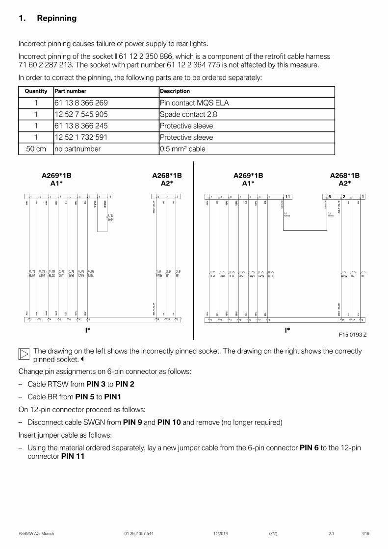
Incorrect pinning causes failure of power supply to rear lights.Incorrect pinning of the socket I 61 12 2 350 886, which is a component of the retrofit cable harness71 60 2 287 213. The socket with part number 61 12 2 364 775 is not affected by this measure.In order to correct the pinning, the following parts are to be ordered separately:
Quantity Part number Description
1 61 13 8 366 269 Pin contact MQS ELA1 12 52 7 545 905 Spade contact 2.81 61 13 8 366 245 Protective sleeve1 12 52 1 732 591 Protective sleeve
50 cm no partnumber 0.5 mm² cable
F15 0193 Z
12611
0,5 SWGN
0,5 SWGN
A269*1BA1*
A269*1BA1*
A268*1BA2*
A268*1BA2*
I*I*
SENS
OR
SENS
OR
The drawing on the left shows the incorrectly pinned socket. The drawing on the right shows the correctlypinned socket.
Change pin assignments on 6-pin connector as follows:– Cable RTSW from PIN 3 to PIN 2– Cable BR from PIN 5 to PIN1On 12-pin connector proceed as follows:– Disconnect cable SWGN from PIN 9 and PIN 10 and remove (no longer required)Insert jumper cable as follows:– Using the material ordered separately, lay a new jumper cable from the 6-pin connector PIN 6 to the 12-pin
connector PIN 11
2. Parts list
© BMW AG, Munich 01 29 2 357 544 11/2014 (Z/Z) 2.1 5/19
BA
C E F GD
I J
H
K L M N O
QQR
P
F15 0184 Z
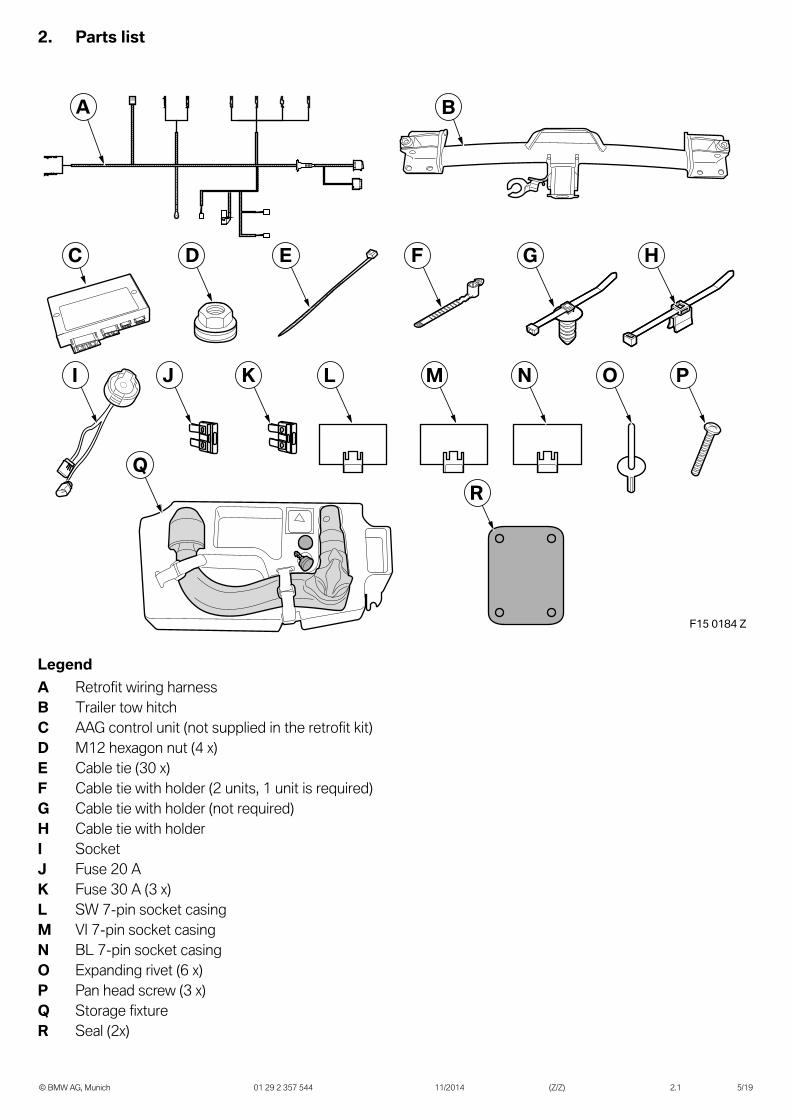
LegendA Retrofit wiring harnessB Trailer tow hitchC AAG control unit (not supplied in the retrofit kit)D M12 hexagon nut (4 x)E Cable tie (30 x)F Cable tie with holder (2 units, 1 unit is required)G Cable tie with holder (not required)H Cable tie with holderI SocketJ Fuse 20 AK Fuse 30 A (3 x)L SW 7-pin socket casingM VI 7-pin socket casingN BL 7-pin socket casingO Expanding rivet (6 x)P Pan head screw (3 x)Q Storage fixtureR Seal (2x)
3. Preparatory work
© BMW AG, Munich 01 29 2 357 544 11/2014 (Z/Z) 2.1 6/19
ISTA No.
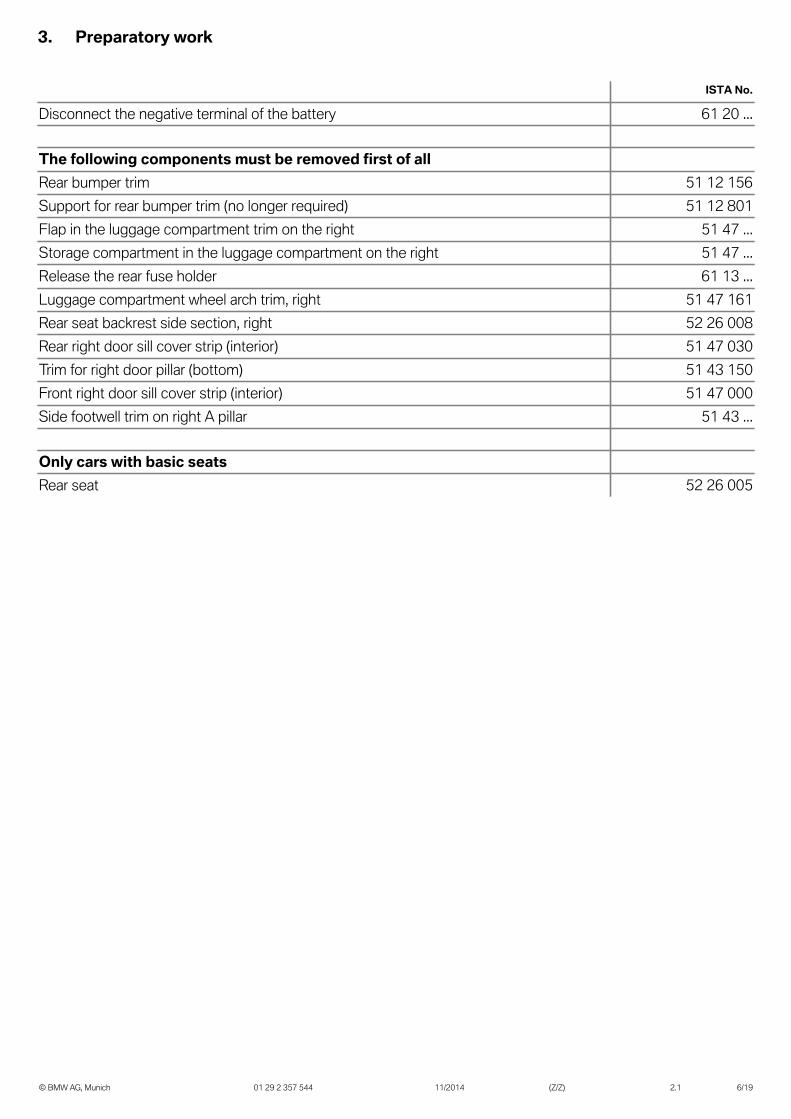
Disconnect the negative terminal of the battery 61 20 ...
The following components must be removed first of allRear bumper trim 51 12 156Support for rear bumper trim (no longer required) 51 12 801Flap in the luggage compartment trim on the right 51 47 ...Storage compartment in the luggage compartment on the right 51 47 ...Release the rear fuse holder 61 13 ...Luggage compartment wheel arch trim, right 51 47 161Rear seat backrest side section, right 52 26 008Rear right door sill cover strip (interior) 51 47 030Trim for right door pillar (bottom) 51 43 150Front right door sill cover strip (interior) 51 47 000Side footwell trim on right A pillar 51 43 ...
Only cars with basic seatsRear seat 52 26 005
4. Retrofit wiring diagram connection diagram
© BMW AG, Munich 01 29 2 357 544 11/2014 (Z/Z) 2.1 7/19
F15 0101 ZA8
A7
A9A10A13
A4 A3A5A6A11A12A14
A2
A1A15A16
A
Item Designation Signal Cable colour/cross-section
Connection location in the car Abbreviation/slot
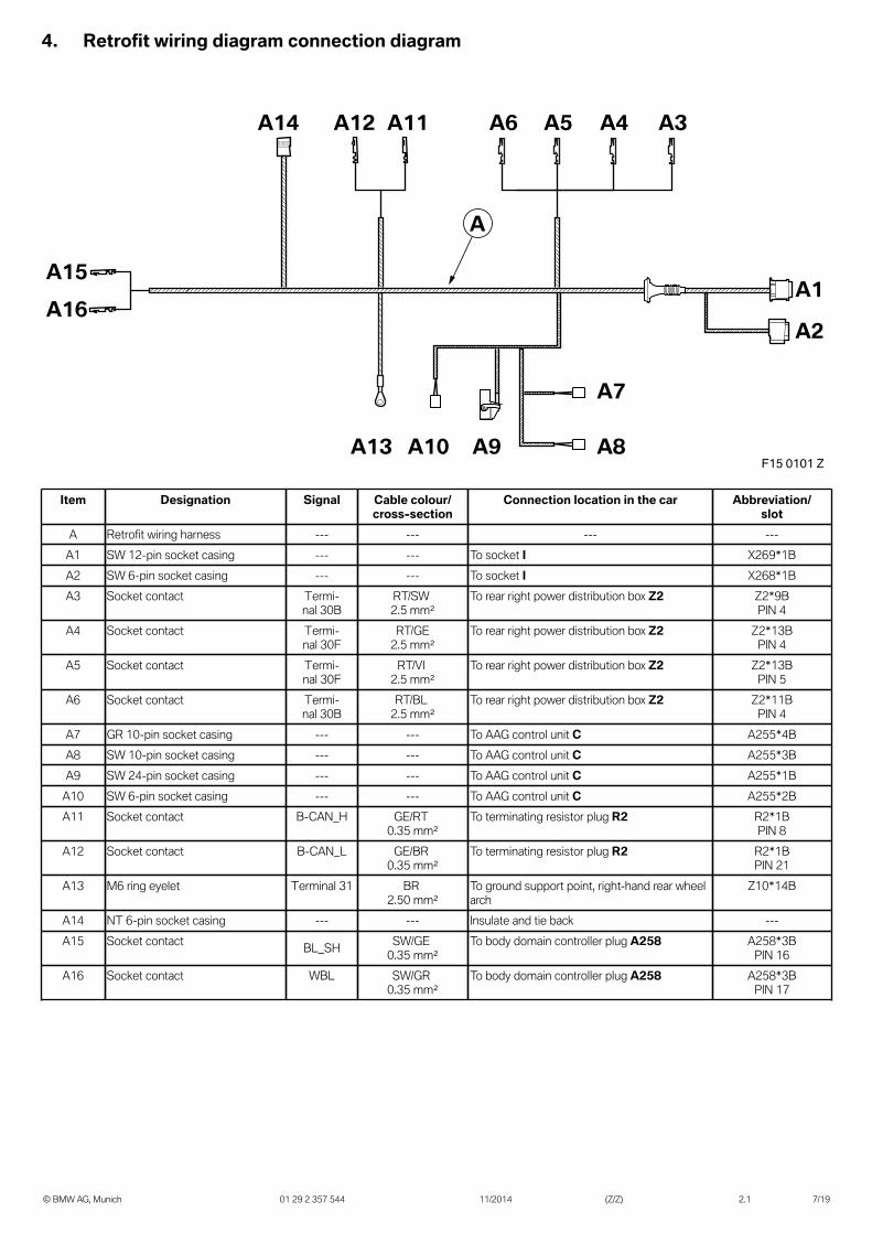
A Retrofit wiring harness --- --- --- ---A1 SW 12-pin socket casing --- --- To socket I X269*1BA2 SW 6-pin socket casing --- --- To socket I X268*1BA3 Socket contact Termi-
nal 30BRT/SW 2.5 mm²
To rear right power distribution box Z2 Z2*9BPIN 4
A4 Socket contact Termi-nal 30F
RT/GE2.5 mm²
To rear right power distribution box Z2 Z2*13BPIN 4
A5 Socket contact Termi-nal 30F
RT/VI 2.5 mm²
To rear right power distribution box Z2 Z2*13BPIN 5
A6 Socket contact Termi-nal 30B
RT/BL 2.5 mm²
To rear right power distribution box Z2 Z2*11BPIN 4
A7 GR 10-pin socket casing --- --- To AAG control unit C A255*4BA8 SW 10-pin socket casing --- --- To AAG control unit C A255*3BA9 SW 24-pin socket casing --- --- To AAG control unit C A255*1B
A10 SW 6-pin socket casing --- --- To AAG control unit C A255*2BA11 Socket contact B-CAN_H GE/RT
0.35 mm²To terminating resistor plug R2 R2*1B
PIN 8A12 Socket contact B-CAN_L GE/BR
0.35 mm²To terminating resistor plug R2 R2*1B
PIN 21A13 M6 ring eyelet Terminal 31 BR
2.50 mm²To ground support point, right-hand rear wheelarch
Z10*14B
A14 NT 6-pin socket casing --- --- Insulate and tie back ---A15 Socket contact BL_SH SW/GE
0.35 mm²To body domain controller plug A258 A258*3B
PIN 16A16 Socket contact WBL SW/GR
0.35 mm²To body domain controller plug A258 A258*3B
PIN 17

5. Installation and cabling diagram
© BMW AG, Munich 01 29 2 357 544 11/2014 (Z/Z) 2.1 8/19
I
1
A5 3
4 2C
5*
F15 0187 Z
A Retrofit wiring harnessC AAG control unitI Socket
1 Rubber grommet2 Rear right power distribution box Z2, plugs Z2*9B, Z2*11B, Z2*13B3 Terminating resistor R2, plug R2*1B4 Ground support point Z10*14B5 Body Domain Controller A258, plug A258*3B for LHD vehicles5* Body Domain Controller A258, plug A258*3B for RHD vehicles
6. Installing the trailer tow hitch, routing and connecting the retrofit wiring harness
© BMW AG, Munich 01 29 2 357 544 11/2014 (Z/Z) 2.1 9/19
2
1
R
F15 0191 Z
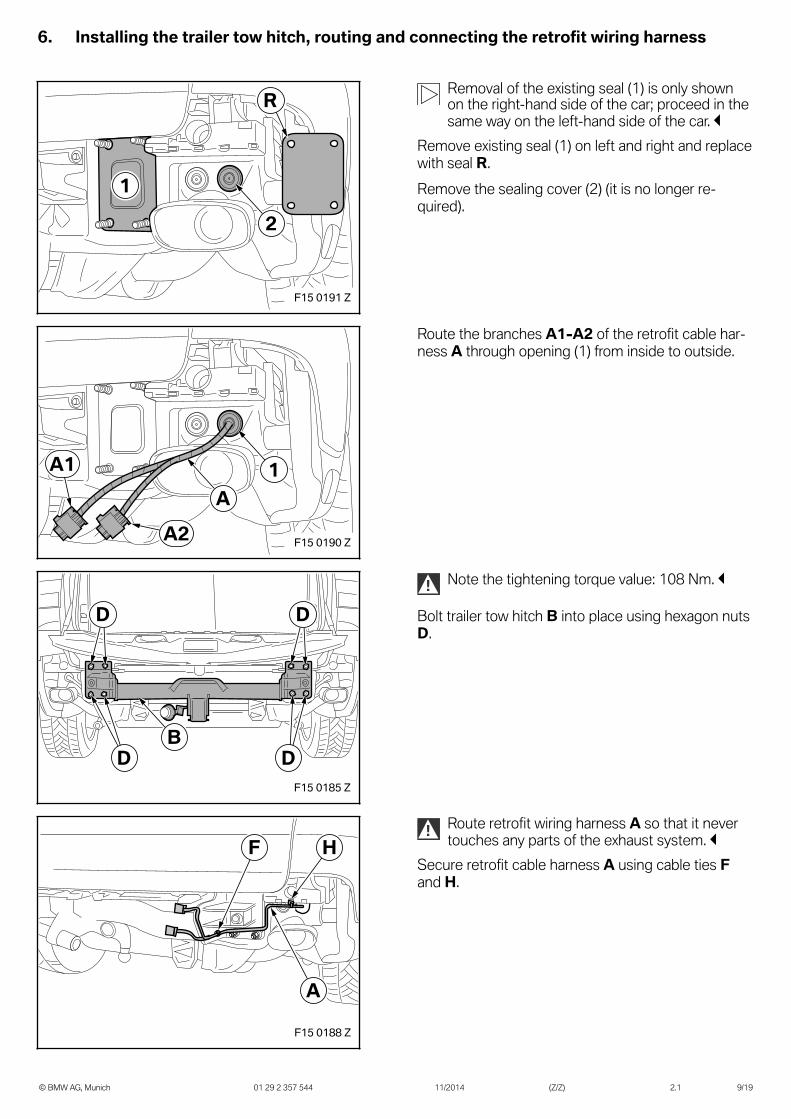
Removal of the existing seal (1) is only shownon the right-hand side of the car; proceed in thesame way on the left-hand side of the car.
Remove existing seal (1) on left and right and replacewith seal R.Remove the sealing cover (2) (it is no longer re-quired).
1A
A1
A2 F15 0190 Z
Route the branches A1-A2 of the retrofit cable har-ness A through opening (1) from inside to outside.
B
D D
D DF15 0185 Z
! Note the tightening torque value: 108 Nm.
Bolt trailer tow hitch B into place using hexagon nutsD.
F H
A
F15 0188 Z
! Route retrofit wiring harness A so that it nevertouches any parts of the exhaust system.
Secure retrofit cable harness A using cable ties Fand H.
6. Installing the trailer tow hitch, routing and connecting the retrofit wiring harness
© BMW AG, Munich 01 29 2 357 544 11/2014 (Z/Z) 2.1 10/19
F15 0182 Z2P
1A
I
A2
A1
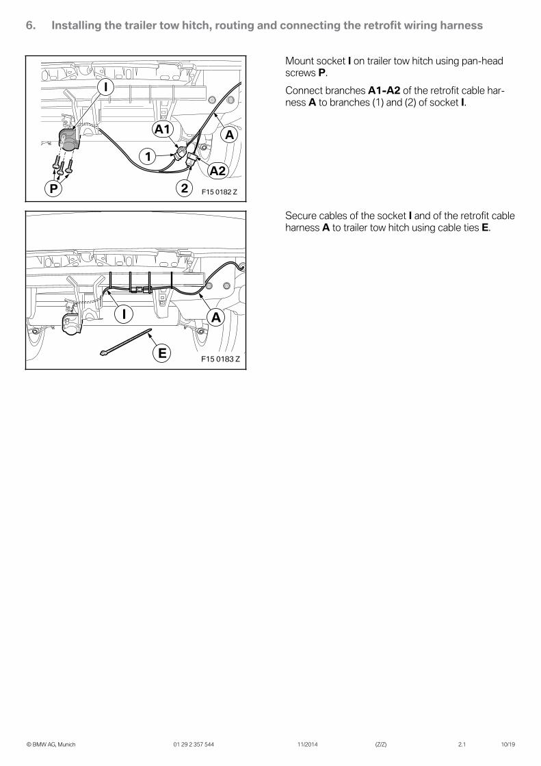
Mount socket I on trailer tow hitch using pan-headscrews P.Connect branches A1-A2 of the retrofit cable har-ness A to branches (1) and (2) of socket I.
F15 0183 ZE
AI
Secure cables of the socket I and of the retrofit cableharness A to trailer tow hitch using cable ties E.
6. Installing the trailer tow hitch, routing and connecting the retrofit wiring harness
© BMW AG, Munich 01 29 2 357 544 11/2014 (Z/Z) 2.1 11/19
A15-A16
A3-A6
A7-A10
A11-A12
Z10*14B
Z2
A
A14 A13
E
F15 0189 Z
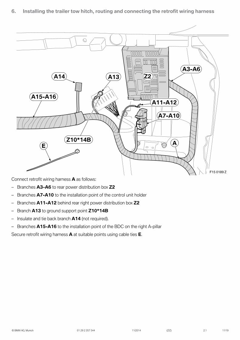
Connect retrofit wiring harness A as follows:– Branches A3–A6 to rear power distribution box Z2– Branches A7-A10 to the installation point of the control unit holder– Branches A11-A12 behind rear right power distribution box Z2– Branch A13 to ground support point Z10*14B– Insulate and tie back branch A14 (not required).– Branches A15-A16 to the installation point of the BDC on the right A-pillarSecure retrofit wiring harness A at suitable points using cable ties E.
6. Installing the trailer tow hitch, routing and connecting the retrofit wiring harness
© BMW AG, Munich 01 29 2 357 544 11/2014 (Z/Z) 2.1 12/19
Z2*9BZ2*13B
A3–A6
Z2*11B
Z2
F15 0103 Z
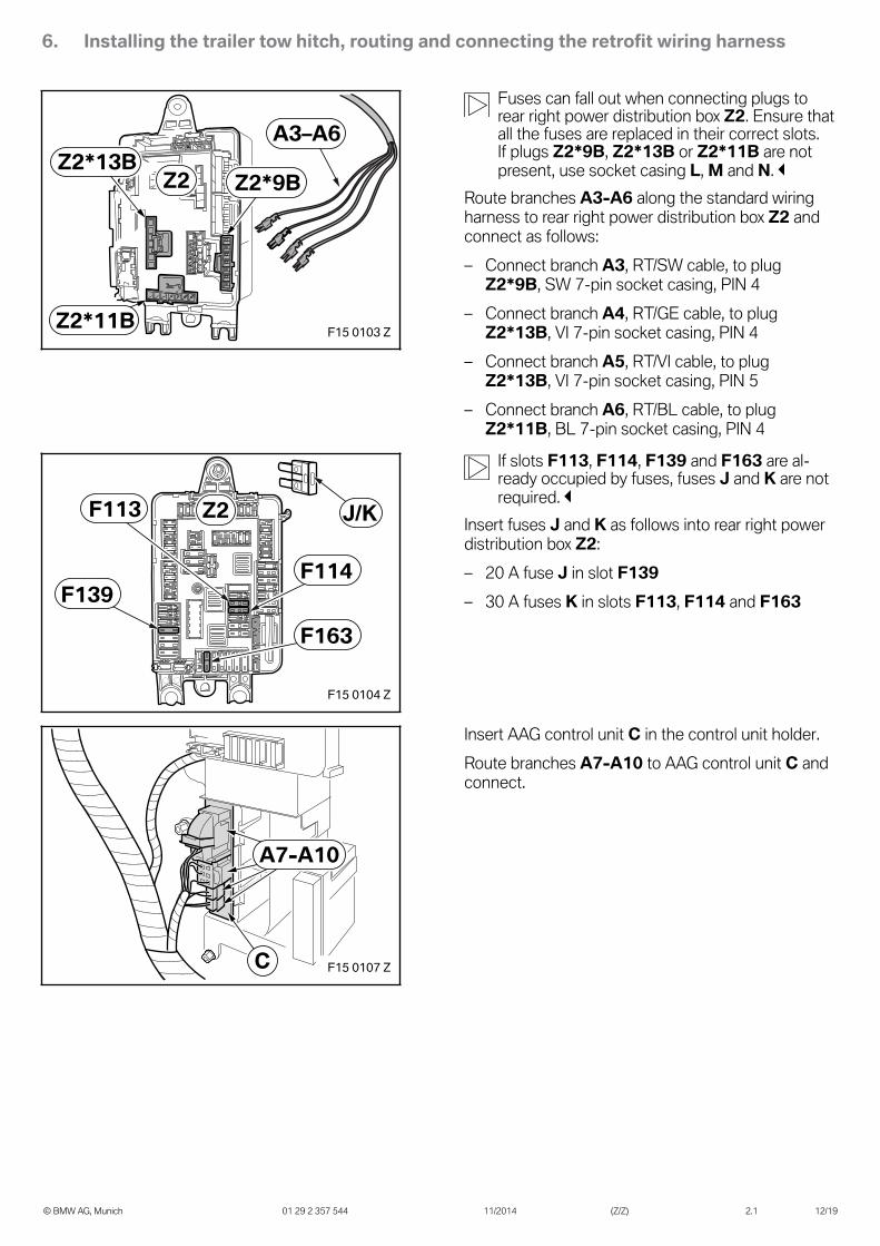
Fuses can fall out when connecting plugs torear right power distribution box Z2. Ensure thatall the fuses are replaced in their correct slots.If plugs Z2*9B, Z2*13B or Z2*11B are notpresent, use socket casing L, M and N.
Route branches A3-A6 along the standard wiringharness to rear right power distribution box Z2 andconnect as follows:– Connect branch A3, RT/SW cable, to plug
Z2*9B, SW 7-pin socket casing, PIN 4– Connect branch A4, RT/GE cable, to plug
Z2*13B, VI 7-pin socket casing, PIN 4– Connect branch A5, RT/VI cable, to plug
Z2*13B, VI 7-pin socket casing, PIN 5– Connect branch A6, RT/BL cable, to plug
Z2*11B, BL 7-pin socket casing, PIN 4
F139F114
F113
F163
Z2 J/K
F15 0104 Z
If slots F113, F114, F139 and F163 are al-ready occupied by fuses, fuses J and K are notrequired.
Insert fuses J and K as follows into rear right powerdistribution box Z2:– 20 A fuse J in slot F139– 30 A fuses K in slots F113, F114 and F163
A7-A10
C F15 0107 Z
Insert AAG control unit C in the control unit holder.Route branches A7-A10 to AAG control unit C andconnect.
6. Installing the trailer tow hitch, routing and connecting the retrofit wiring harness
© BMW AG, Munich 01 29 2 357 544 11/2014 (Z/Z) 2.1 13/19
F15 0105 Z
R2*1B
A11-A12R2
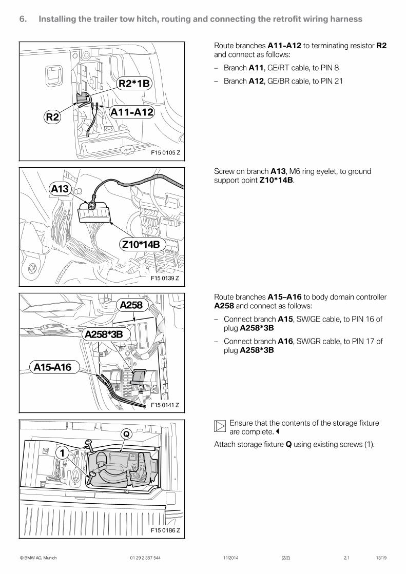
Route branches A11-A12 to terminating resistor R2and connect as follows:– Branch A11, GE/RT cable, to PIN 8– Branch A12, GE/BR cable, to PIN 21
A13
Z10*14B
F15 0139 Z
Screw on branch A13, M6 ring eyelet, to groundsupport point Z10*14B.
A258*3B
A15-A16
A258
F15 0141 Z
Route branches A15–A16 to body domain controllerA258 and connect as follows:– Connect branch A15, SW/GE cable, to PIN 16 of
plug A258*3B– Connect branch A16, SW/GR cable, to PIN 17 of
plug A258*3B
Q
1
F15 0186 Z
Ensure that the contents of the storage fixtureare complete.
Attach storage fixture Q using existing screws (1).
7. Concluding work and coding
© BMW AG, Munich 01 29 2 357 544 11/2014 (Z/Z) 2.1 14/19
The retrofit system requires programming / coding.– Expanding rivets O are required to secure the rear bumper trim to the wheel arches– Connect the battery– Connect the battery charger to the car– Connect the car to the ISTA workshop system– Call up the ISTA/P car programming facility– If using ISTA/P, please note the instructions provided in the ISTA/P application documentation– Select the "Removable trailer tow hitch" retrofit using the – Conversions – path and work through the action
plan created– If necessary, carry out a car test using the ISTA system and note or work through any entered error memory
8. Wiring diagram
© BMW AG, Munich 01 29 2 357 544 11/2014 (Z/Z) 2.1 15/19
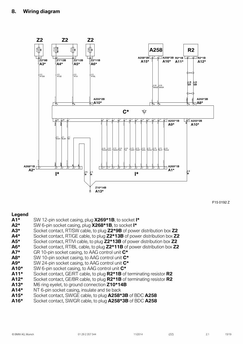
F15 0192 Z
2.5 RTSW
2.5 RTGE
2.5 RTVI
2.5 RTBL
30F_
F113
_HR
30F_
F114
_HR
30F_
F114
_HR
30F_
F139
_HR
30F_
F139
_HR
SENS
OR_
GND
SENS
OR_
GND
2.5 WSRT
2.5 BLBR
2.5 BR
7
S_SI
CH_1
S_SI
CH_1
S_SI
CH_2
S_SI
CH_2
1112
105
0.35 GE
55A
55A
2
12
0.75 GRRT
58AR
58AR
4
15
0.75 GNRT
49AR
49AR
3
18
0.75 GEBL
RSA
RSA
7
19
0.75 GRSW
58AL
58AL
6
23
0.75 BLGE
49AL
49AL
1
24
0.75 BLRT
AEAE
8
11
0.35 WS
0.35 GNVI
54A
54A
5
3
0.75 SWWS
HALL
+HA
LL+
10
6
0.35 WSGN
0.35 WSGE
HALL
SENS
OR
HALL
SENS
OR
9
9
R2
0.35 SWGE
0.35 SWGR
BL_S
HBL
_SH
WBL
WBL
30B_
F163
_HR
30B_
F163
_HR
8 21
Z2*13BA5*
Z2 Z2Z2
C*
Z2*9BA3*
Z1*13BA4*
Z2*11BA6*
A255*2BA10*
A255*3BA8*
A255*2BA10*
A255*1BA9*
A269*1BA1*
A268*1BA2*
Z10*14BA13*
I* I*
F139
F114
F163
F113
4 4 45
30F_
F113
_HR
2 3 5 6 4 1
R2*1BA12*
R2*1BA11*
A258A258*3BA16*
A258*3BA15*
16 17
LegendA1* SW 12-pin socket casing, plug X269*1B, to socket I*A2* SW 6-pin socket casing, plug X268*1B, to socket I*A3* Socket contact, RT/SW cable, to plug Z2*9B of power distribution box Z2A4* Socket contact, RT/GE cable, to plug Z2*13B of power distribution box Z2A5* Socket contact, RT/VI cable, to plug Z2*13B of power distribution box Z2A6* Socket contact, RT/BL cable, to plug Z2*11B of power distribution box Z2A7* GR 10-pin socket casing, to AAG control unit C*A8* SW 10-pin socket casing, to AAG control unit C*A9* SW 24-pin socket casing, to AAG control unit C*A10* SW 6-pin socket casing, to AAG control unit C*A11* Socket contact, GE/RT cable, to plug R2*1B of terminating resistor R2A12* Socket contact, GE/BR cable, to plug R2*1B of terminating resistor R2A13* M6 ring eyelet, to ground connection Z10*14BA14* NT 6-pin socket casing, insulate and tie backA15* Socket contact, SW/GE cable, to plug A258*3B of BDC A258A16* Socket contact, SW/GR cable, to plug A258*3B of BDC A258
8. Wiring diagram
© BMW AG, Munich 01 29 2 357 544 11/2014 (Z/Z) 2.1 16/19
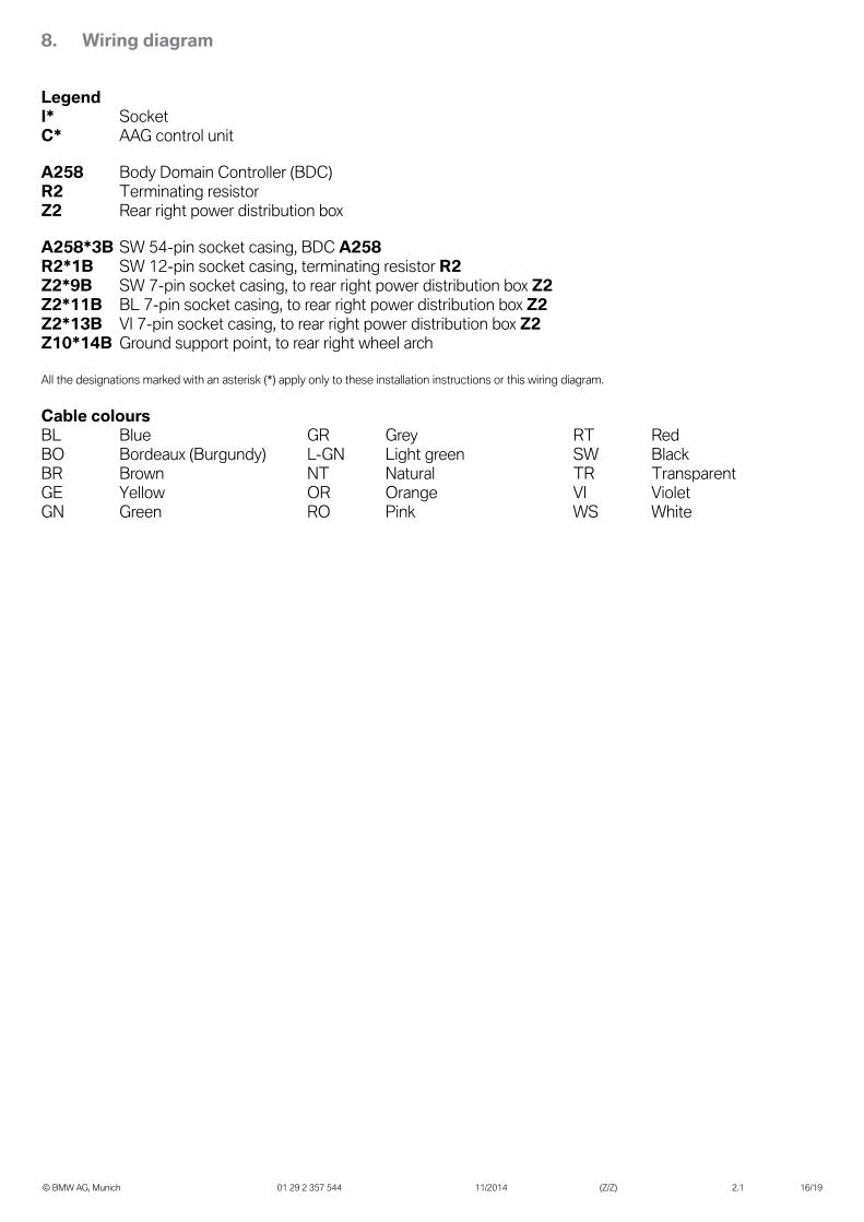
LegendI* SocketC* AAG control unit
A258 Body Domain Controller (BDC)R2 Terminating resistorZ2 Rear right power distribution box
A258*3B SW 54-pin socket casing, BDC A258R2*1B SW 12-pin socket casing, terminating resistor R2Z2*9B SW 7-pin socket casing, to rear right power distribution box Z2Z2*11B BL 7-pin socket casing, to rear right power distribution box Z2Z2*13B VI 7-pin socket casing, to rear right power distribution box Z2Z10*14B Ground support point, to rear right wheel arch
All the designations marked with an asterisk (*) apply only to these installation instructions or this wiring diagram.
Cable coloursBL Blue GR Grey RT RedBO Bordeaux (Burgundy) L-GN Light green SW BlackBR Brown NT Natural TR TransparentGE Yellow OR Orange VI VioletGN Green RO Pink WS White
9. Statutory regulations pursuant to EC Directive 94/20/EC
© BMW AG, Munich 01 29 2 357 544 11/2014 (Z/Z) 2.1 17/19
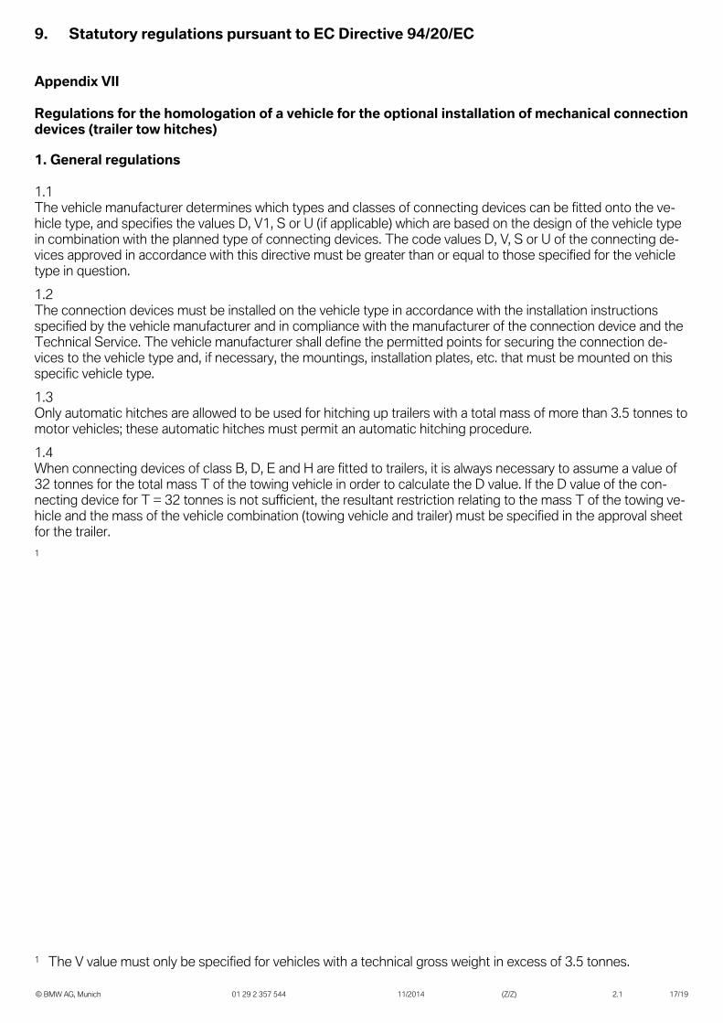
Appendix VII
Regulations for the homologation of a vehicle for the optional installation of mechanical connectiondevices (trailer tow hitches)
1. General regulations
1.1The vehicle manufacturer determines which types and classes of connecting devices can be fitted onto the ve-hicle type, and specifies the values D, V1, S or U (if applicable) which are based on the design of the vehicle typein combination with the planned type of connecting devices. The code values D, V, S or U of the connecting de-vices approved in accordance with this directive must be greater than or equal to those specified for the vehicletype in question.1.2The connection devices must be installed on the vehicle type in accordance with the installation instructionsspecified by the vehicle manufacturer and in compliance with the manufacturer of the connection device and theTechnical Service. The vehicle manufacturer shall define the permitted points for securing the connection de-vices to the vehicle type and, if necessary, the mountings, installation plates, etc. that must be mounted on thisspecific vehicle type.1.3Only automatic hitches are allowed to be used for hitching up trailers with a total mass of more than 3.5 tonnes tomotor vehicles; these automatic hitches must permit an automatic hitching procedure.1.4When connecting devices of class B, D, E and H are fitted to trailers, it is always necessary to assume a value of32 tonnes for the total mass T of the towing vehicle in order to calculate the D value. If the D value of the con-necting device for T = 32 tonnes is not sufficient, the resultant restriction relating to the mass T of the towing ve-hicle and the mass of the vehicle combination (towing vehicle and trailer) must be specified in the approval sheetfor the trailer.1
1 The V value must only be specified for vehicles with a technical gross weight in excess of 3.5 tonnes.
9. Statutory regulations pursuant to EC Directive 94/20/EC
© BMW AG, Munich 01 29 2 357 544 11/2014 (Z/Z) 2.1 18/19
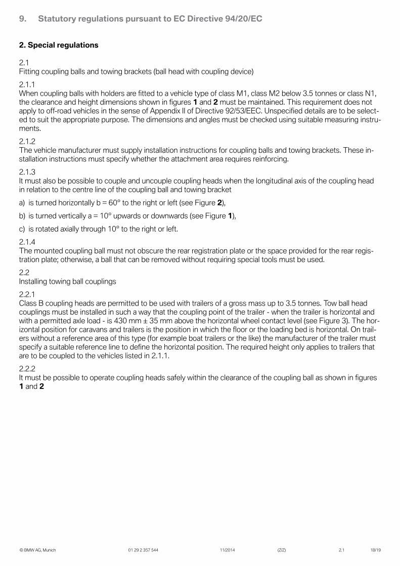
2. Special regulations
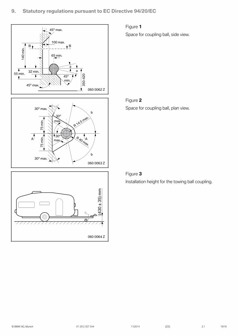
2.1Fitting coupling balls and towing brackets (ball head with coupling device)2.1.1When coupling balls with holders are fitted to a vehicle type of class M1, class M2 below 3.5 tonnes or class N1,the clearance and height dimensions shown in figures 1 and 2 must be maintained. This requirement does notapply to off-road vehicles in the sense of Appendix II of Directive 92/53/EEC. Unspecified details are to be select-ed to suit the appropriate purpose. The dimensions and angles must be checked using suitable measuring instru-ments.2.1.2The vehicle manufacturer must supply installation instructions for coupling balls and towing brackets. These in-stallation instructions must specify whether the attachment area requires reinforcing.2.1.3It must also be possible to couple and uncouple coupling heads when the longitudinal axis of the coupling headin relation to the centre line of the coupling ball and towing bracketa) is turned horizontally b = 60° to the right or left (see Figure 2),b) is turned vertically a = 10° upwards or downwards (see Figure 1),c) is rotated axially through 10° to the right or left.2.1.4The mounted coupling ball must not obscure the rear registration plate or the space provided for the rear regis-tration plate; otherwise, a ball that can be removed without requiring special tools must be used.2.2Installing towing ball couplings2.2.1Class B coupling heads are permitted to be used with trailers of a gross mass up to 3.5 tonnes. Tow ball headcouplings must be installed in such a way that the coupling point of the trailer - when the trailer is horizontal andwith a permitted axle load - is 430 mm ± 35 mm above the horizontal wheel contact level (see Figure 3). The hor-izontal position for caravans and trailers is the position in which the floor or the loading bed is horizontal. On trail-ers without a reference area of this type (for example boat trailers or the like) the manufacturer of the trailer mustspecify a suitable reference line to define the horizontal position. The required height only applies to trailers thatare to be coupled to the vehicles listed in 2.1.1.2.2.2It must be possible to operate coupling heads safely within the clearance of the coupling ball as shown in figures1 and 2
9. Statutory regulations pursuant to EC Directive 94/20/EC
© BMW AG, Munich 01 29 2 357 544 11/2014 (Z/Z) 2.1 19/19
65 min.
aa
100 max.
45° min.
45° max.
45° max.
32 min.55 min.
140
min
.
350-
420
B B
060 0062 Z
Figure 1Space for coupling ball, side view.
30° max.
30° max.
30°max.
30°max.
R 14.5 max.
R 40 max.75 m
in.
75 m
in.
A A
b
b
060 0063 Z
Figure 2Space for coupling ball, plan view.
(430
± 3
5) m
m
060 0064 Z
Figure 3Installation height for the towing ball coupling.