original article design and implementation model for
TRANSCRIPT
Abstract Linearization sensors characteristics becomes very interest field for researchers due to the importance in enhance the system performance, measurement accuracy, system design simplicity (hardware and software), reduce system cost, ..etc. in this paper, two approaches has been introduced in order to linearize the sensor characteristics; first is signal condition circuit based on lock up table (LUT) which this method performed for linearize NTC sensor characteristic. Second is ratiometric measurement equation which this method performed for linearize LVDT sensor characteristic. The proposed methods has been simulated by MATLAB, and then implemented by using Anadigm AN221E04 Field Programmable Analog Array (FPAA) development kit which several experiments performed in order to improve the performance of these approaches. Index Terms— Characteristic linearization, LUT, NTC, LVDT, FPAA.
I. INTRODUCTION The field of sensors science takes a great interest by control and system researchers due to important applications of this science like applications of industrial, medical, aerospace, scientific, military, environmental etc. the principle concept of sensing is to convert physical parameters into electrical signals. Sensors are essential in control and instrumentation, which used for acquires information from the external world that then must be processed by control systems. There are many types of sensors include temperature, pressure, range, etc. which required adopting the automation control systems in the manufactures. In addition, the development of the sensors depending on important sensors characteristics like sensor size, accuracy, power consumption, linearity, etc. must be concerned [1-2]. The important characteristic parameter of sensor that always must be considered is linearization to assure the accuracy of the automation control system. The physical information that measured by electrical or mechanical sensors is frequently
affected by offset, gain and nonlinear errors. These errors needs to compensation in order to improve the sensor accuracy and sensitivity. There several methods can be used to linearize the sensor characteristics. Some of linearization methods are based on dedicated electronic circuits, whose transfer function is the inverse of the characteristic to be linearized, and others depend on Digital Signal Processing (DSP) concepts [3–5]. In recent years, the sensor linearization characteristic is interested from the researchers because the linear characteristic will increase system performance and reduce the system complexity and its cost. C. Reiser, L. Znamirowski, etc. in 1998 presented results of work on adaptive filtering with dynamic reconfiguration based on two parallel FPAA chips cooperating with a digital control system represented by Field Programmable Gate Arrays (FPGA) [6]. P. L. Yakimov in 2004 built circuit include sensor interfacing by using FPAA, which platinum resistance thermometers (Pt100) has been used as temperature sensor, and in this
Design and Implementation Model for Linearization Sensor Characteristic by FPAA
Alaa Abdul Hussein Salman Fadhil Rahma Tahir Mofeed Turky Rashid Electrical Engineering
Department Electrical Engineering
Department Computer Science Department
Basrah University Basrah University Shatt Al-Arab College University Basrah, Iraq. Basrah, Iraq. Basrah, Iraq
[email protected] [email protected] [email protected], [email protected]
165165165
Iraqi Journal for Electrical and Electronic EngineeringOriginal Article
Open Access
Received: 5 September 2015 Revised: 9 October 2015 Accepted: 18 October 2015 Vol. 11| Issue 2 | December 2015DOI: 10.37917/ijeee.11.2.3

system the linearization characteristics has been achieved by FPAA [7]. F. T. Koparanov in 2008 invest of FPAA based signal conditioning circuit for Inductive Displacement Transducer (IDT). In this work, the circuit has been discussed for applicable in the development of switched-capacitor signal conditioning blocks for ASICs and SoCs [8]. The concept of linearization process is convert nonlinear characteristics to linear characteristics as shown in Fig. 1, which the first step is derive a function y=f(x) represent the nonlinear characteristic, when z=f-1(x) has been derived, the linear characteristic is the result of multiplication of nonlinear function with its inverse function. In this paper, the linearization process has been achieved for Negative Temperature Coefficient (NTC) thermistor by using invers function of nonlinear characteristic based on lock up table (LUT). Then the Linear Variable Differential Transformer (LVDT) characteristic will be linearized based on ratiometric measurement equation. These linearization processes has been achieved by FPAA.
Fig. 1: The linearization process.
II. NEGATIVE TEMPERATURE COEFFICIENT
(NTC) THERMISTOR
NTC thermistor is thermally sensitive resistor which it is made from a mixture of Mn, Ni, Co, Cu, Fe oxides, its form and symbol is shown in Fig. 2. The NTC is semi-conducting ceramic [6]. This semi-conducting material reacts as an NTC resistor, whose resistance decreases with increasing temperature. In general the NTC device life time can be calculated by ∆R/R of thermistors held at ± 125C in air for different periods of time, up to 1000 hours. For commercial components ∆R/R is usually around 0.5 to 2% [9].
(a)
(b)
Fig. 2: (a) NTC thermistor, (b) NTC symbol.
The NTC thermistor is sensitive to temperature change. To calculate the value of sensitivity index (B), it is necessary to know the resistances values R1 and R2 of the NTC thermistor that corresponding to temperatures degree T1 and T2. The relation among to R1, R2, T1, and T2 are given by [10]:
−=
2121
11expTT
BRR (1)
−
=2
1
12
21 lnRR
TTTTB (2)
Usually, B is calculated according to the values of T1 and T2 at 298.15 K and 358.15 K respectively. From (1) and (2) can be getting:
( )
−
=
TTB
RRT
11exp25
85/25
25 (3)
Where RT, T, and T25 are thermistor resistance, temperature in kelvin, and kelvin temperature at 25 oC. Equation (3) indicated that the NTC thermistor characteristic is nonlinear as shown in Fig. 3.
166
Alaa Abdul Hussein SalmanVol. 11| Issue 2 | December 2015

Fig. 3: NTC thermistor characteristic.
III. LINEAR VARIABLE DIFFERENTIAL
TRANSFORMER (LVDT)
The Linear Variable Differential Transformer (LVDT) is an electromechanical transducer that can convert the rectilinear motion of an object to which it is coupled into a corresponding electrical signal. The typical LVDT is shown in Fig. 4 [11].
Fig. 4: The components of a typical LVDT [11].
The LVDT introduced in the market in the mid-1940s, it made from stainless steel and rated for operation in high temperatures to withstand the harsh environments. Since the 1950s, power generation and major factories remain one of the largest market segments serviced by LVDT linear position sensors. One of the important things that characterize of linear position sensors can be measured movements as small parts of a
millimeter up to several inches, but some are capable of measuring positions up to m [11]. LVDT is a simple device with only a few coils of wire and a ferrous core; LVDTs can withstand high levels of shock and vibration, and still operate according to their specifications, this is very necessary to build an integrated system that works with high accuracy to ensure the quality of work [12]. An LVDT is a cylindrical transformer with one primary and two secondary windings, all of these windings are wrapped around an open air core. A not connected ferrous slug resides at some position within this otherwise hollow core. The way to understanding LVDT function it to consider its construction as shown in Fig. 5 and how the primary signal is coupled to the secondary windings [13].
Fig. 5: A basic LVDT - Cross Section View.
AC signal is applied to the primary side. If the ferrous core is moved to the "B" side secondary windings, the coupling from the primary to the B side secondary will increase and the coupling to the A side secondary will decrease [11]. The amplitude of the signal at Vb (and Va) directly proportional to the position of the movable core. The LVDT design is much more refined than presented above, the density, number, and overlap of windings, the end to end bias of winding numbers… etc., are just some of the parameters show you in the precision LVDT design [11]. Most of the machines present notoriously noisy in its electrical environment, therefor any stray noise coupled to the Vb lines will be read by the Vb monitoring circuit and mistakenly interpreted as displacement information. So, any wiggle in the primary’s driving amplitude will be directly coupled to Vb and will also negatively affect accuracy. To resolve the issue, the simple
167
Alaa Abdul Hussein SalmanVol. 11| Issue 2 | December 2015

solution can be used for both Va and Vb signals by perform a ratiometric measurement equation. The use of a ferromagnetic core in the LVDT sensors is essential to let the magnetic flux coupled with the secondary coils (and so their voltages) be a function of the position. However, the use of nonlinear ferromagnetic materials makes the sensors sensitive to external polarizing magnetic fields. The nonlinear of the material (inevitable in ferromagnetism) as a matter of fact, lets the external field modulate the first harmonic of the coils voltage, affecting in this way the sensor’s reading [14]. Theoretically, the LVDT sensor has no limit in terms of resolution, which is then determined by the conditioning and acquisition system of the primary and secondary coils (Transducer), which its schematic shown in Fig. 6.
Fig. 6: Primary and Secondary Coils Schematic.
The characteristics of the LVDT affected by two components the first, linear motion symbolized its (displacement). And the second, the output voltage across the terminal of the secondary coils. Va and Vb of two secondary coils are shown in Fig. 7.
Fig. 7: Characteristics of LVDT.
From the Terminals of secondary coils A and B, Va and Vb can be measured, respectively. So to obtain (Vout) ratiometric measurement equation has been used as follow [14][15].
VbVaVbVaVout +
−= (4)
IV. LINEARIZATION METHODOLOGY
A. Linearization of NTC Characteristic
The nonlinear characteristic of NTC has been linearized by using signal conditioning circuit which this circuit achieved by deriving an inverse function f-1(x). The proposed scheme of the linearization process contains an inverse function is shown in Fig. 8. The MATLAB Simulink has been used to simulate the proposed scheme.
Fig. 8: Simulink model of signal conditioning circuit for NTC.
The proposed inverse function model is given by:
( ) ( )2/1exp axbaxy −−= (5)
Where the parameters used in simulation are a, b, c, d, e, and k are (100/35, 0.2, 0.1, -0.9, 0.05, and 90). It is noted that, the stages of implementation of the NTC scheme as ramp function and f(x) section represents simulation characteristic, as shown in Fig. 9.a. The block inverse of f(x) simulates the proposed inverse function as depicted in Fig. 9.b. The output of this simulation scheme represents the overall linearization processes. From Fig. 9.c can be observed that the successful of the proposed scheme and the inverse function, that its evidence from the straight line as shown in Fig. 9.c.
168
Alaa Abdul Hussein SalmanVol. 11| Issue 2 | December 2015

(a) NTC characteristic.
(b) The proposed inverse function.
(c) NTC linear characteristic.
Figure (9): NTC characteristic linearization process.
B. Linearization of LVDT Characteristic
The nonlinear characteristic of the LVDT sensor can be linearized by using ratiometric measurement equation described in the section (III). Fig. 10 shows the simulink scheme model of the signal conditioning circuit proposed for LVDT [16]. The signal conditioning circuit is used for the extraction the information from the signal at the output of the LVDT which represented the displacement measurement. The proposed model is based on full-wave analog rectifiers. The input signal (displacement of the core D) changes between 25 mm to 32 mm. The two measurement signals to the secondary coils Vout1 (Va) and Vout2 (Vb). Every coil feeds to the full-wave rectifier, which the output signals has been subtracted. Linearization curve by using ratiometric measurement equation is shown in Fig. 11. Where a, b, c, and k (1.5, 3.57, 1.25, and -2.5) respectively.
Constant (k)
- -
Gain a
Gain b
LPF Gain c
Vout
Sine wave
Fig. 10: Simulink model of signal conditioning
circuit for LVDT.
Figure (11): Linearization of LVDT characteristic by ratiometric measurement equation.
169
Alaa Abdul Hussein SalmanVol. 11| Issue 2 | December 2015

V. FPAA IMPLEMENTATION OF LINEARIZATION PROCESS.
In this section, two linearization models have been achieved by FPAA. The first one is NTC characteristics linearization model which signal conditioning circuit based on LUT has been used for this purpose. The other one is LVDT characteristics linearization model based on ratiometric measurement equation. Basically in this work the Anadigm AN221E04 FPAA kit has been used which it is shown in Fig. 12.
a. The architecture of AN221E04 FPAA chip
b. Anadigm development board AN221K04-v4.
Fig. 12: Anadigm AN221E04 FPAA kit.
A. FPAA based NTC characteristic linearization
In the proposed application (NTC conditioning by FPAA) as shown in Fig. 13, an FPAA has been used to realize an adaptive conditioning system of the NTC sensor by Anadigm AN221E04 FPAA kit. The input cells which is called low offset chopper, it is used for a differential input cell with the filter turned off. The chopper amplifier has an input offset less than 100 mV. This allows small input signals to be accurately amplified so that they will be less affected by higher input offsets in the switched capacitor core of the chip. A filter has been used to attenuate the signal component at the chopper clock frequency should typically follow the chopper amplifier. All these details: clocks FPAA, I/O cells of the FPAA. FPAA configurable analog modules are illustrated in Fig. 14. In this design LUT has been loaded which is generated by simulation of NTC catachrestic linearization model by MATLAB that described in previous section.
V = 20 volt
R = 26.633 kΩ
NTC
GND
Fig. 13: FPAA based NTC characteristics
linearization. Several experiments have been achieved in order to record the results. Fig. 15 shows the complete experiment setup of FPAA system that used to linearized NTC characteristics which the PC has been used to program FPAA; also it is used to download LUT in to FPAA. Digital thermometer type WT-1 as shown in Fig. 15 has been used to record temperature of the water. Its features specifications are (Temperature range: -50 oC to +300 oC; Distinguishing rate: 0.1 oC; res: (-20 oC to 80 oC) ±1 oC; Equips magnitude of voltage: DC 1.5 V). The output result of NTC
170
Alaa Abdul Hussein SalmanVol. 11| Issue 2 | December 2015

characteristic linearization experiment is shown in Fig. 16.
Fig. 14: Loading LUT for FPAA.
Thermometer NTC FPAA Development Kit
Fig. 15: NTC characteristics linearization
experiment setup.
Fig. 16: NTC linear characteristic.
B. FPAA based LVDT characteristic linearization
An Anadigm AN221E04 FPAA has been used to realize an adaptive conditioning system of the LVDT sensor which this system achieves LVDT characteristic linearization, the proposed system is shown in Fig. 17.
Primary coil
Secondary coil
Core
Fig. 17: FPAA based LVDT characteristic
linearization.
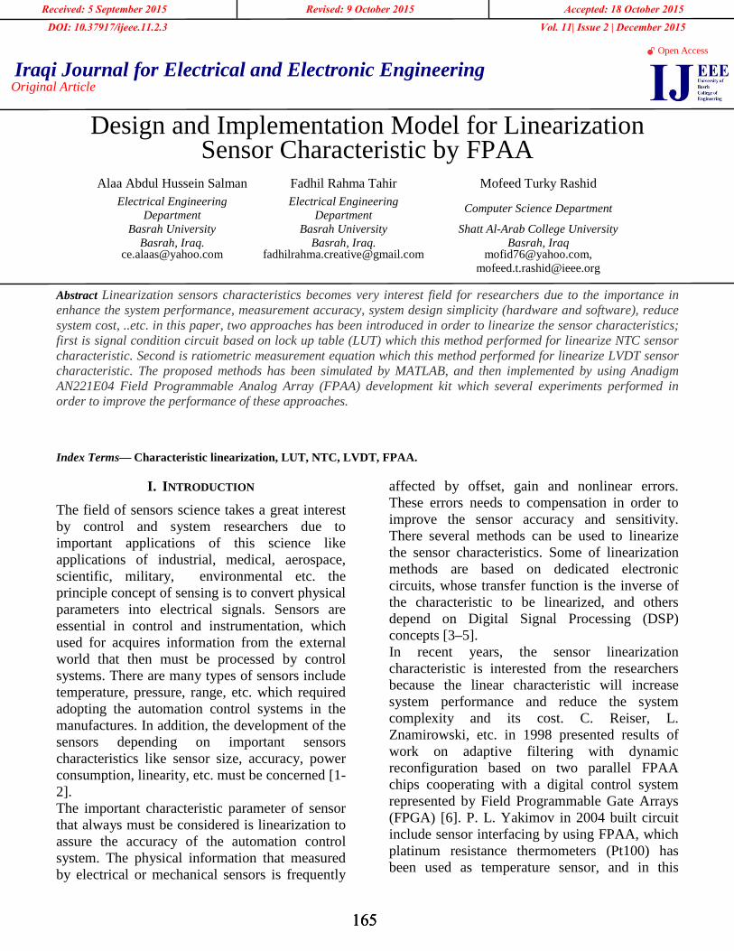
Several experiments have been achieved in order to perform LVDT characteristic linearization. The FPAA based LVDT characteristic linearization experiment setup is shown in Fig. 18, which mechanical structure has been built in order to achieve accurate liner motion for the core of LVDT. So the main components that compound mechanical structures are: Aluminum L shape stand which used as based for mechanical structure; and digital caliper which used to measure accurate distance for measurement
171
Alaa Abdul Hussein SalmanVol. 11| Issue 2 | December 2015
calibration. Anadigm AN221E04 FPAA has been programmed by PC as shown in Fig. 18.
Digital caliper LVDT FPAA Development Kit Aluminum L shape stand
Fig. 18: LVDT characteristics linearization experiment setup.
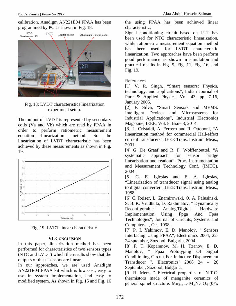
The output of LVDT is represented by secondary coils (Va and Vb) which are read by FPAA in order to perform ratiometric measurement equation linearization method. So the linearization of LVDT characteristic has been achieved by these measurements as shown in Fig. 19.
Fig. 19: LVDT linear characteristic.
VI. CONCLUSION In this paper, linearization method has been performed for characteristics of two sensors types (NTC and LVDT) which the results show that the outputs of these sensors are linear. In our approaches, we are used Anadigm AN221E04 FPAA kit which is low cost, easy to use in system implementation, and easy to modified system. As shown in Fig. 15 and Fig. 16
the using FPAA has been achieved linear characteristic. Signal conditioning circuit based on LUT has been used for NTC characteristic linearization, while ratiometric measurement equation method has been used for LVDT characteristic linearization. Two approaches have been perform good performance as shown in simulation and practical results in Fig. 9, Fig. 11, Fig. 16, and Fig. 19. References [1] V. R. Singh, “Smart sensors: Physics, technology, and applications”, Indian Journal of Pure & Applied Physics, Vol. 43, pp. 7-16, January 2005. [2] F. Silva, “Smart Sensors and MEMS: Intelligent Devices and Microsystems for Industrial Applications”, Industrial Electronics Magazine, IEEE, Vol. 8, Issue 3, 2014. [3] L. Cristaldi, A. Ferrero and R. Ottoboni, “A linearization method for commercial Hall-effect current transducers”, IEEE Trans. Instrum. Meas., 2001. [4] G. De Graaf and R. F. Wolffenbuttel, “A systematic approach for sensor bridge linearisation and readout”, Proc. Instrumentation and Measurement Technology Conf. (IMTC), 2004. [5] G. E. Iglesias and E. A. Iglesias, “Linearization of transducer signal using analog to digital converter”, IEEE Trans. Instrum. Meas., 1988. [6] C. Reiser, L. Znamirowski, O. A. Palusinski, S. B. K. Vrudhula, D. Rakhmatov, " Dynamically Reconfigurable Analog/Digital Hardware Implementation Using Fpga And Fpaa Technologies", Journal of Circuits, Systems and Computers, , Oct. 1998. [7] P. I. Yakimov, E. D. Manolov, " Sensors Interfacing Using FPAA", Electronics 2004, 22-24 sptember, Sozopol, Bulgaria, 2004. [8] F. T. Koparanov, M. H. Tzanov, E. D. Manolov, " Fpaa Prototyping Of Signal Conditioning Circuit For Inductive Displacement Transducer ", Electronics’ 2008 24 – 26 September, Sozopol, Bulgaria. [9] R. Metz, " Electrical properties of N.T.C. thermistors made of manganite ceramics of general spinel structure: Mn3–x –x' MxNx' O4 (0≤x
172
Alaa Abdul Hussein SalmanVol. 11| Issue 2 | December 2015

+x'≤1; M and N being Ni, Co or Cu). Aging phenomenon study", Journal Of Materials Science, Vol. 35, pp.4705 – 4711, 2000. [10] Pierre-Laurent Doumergue, "Using NTC Temperature Sensors Integrated into Power Modules", Advanced Power Technology, 2004. [11] Jinhui Fan, Songmin Jia1, Wei Lu, Zhihong Wang, Xiuzhi Li, Jinbo Sheng, " Application of LVDT Sensor Data Acquisition System Based on PCI-1716", IEEE, pp.548-552, 2011. [12] John Matlack, Lee Hudson, "LVDT Sensors Serve Crucial Role In Gas Turbine Operating Efficiency", Diesel & Gas Turbine Worldwide, pp.18-26, 2012. [13] Giovanni Spiezia, Roberto Losito, Michele Martino, Alessandro Masi, and Antonio Pierno, "Automatic Test Bench for Measurement of Magnetic Interference on LVDTs", IEEE Transactions On Instrumentation And Measurement, Vol. 60, No. 5, pp. 1802-1810, MAY 2011. [14] Alessandro Masi, Alessandro Danisi, Roberto Losito, and Yves Perriard, "Characterization of Magnetic Immunity of an Ironless Inductive Position Sensor", IEEE Sensors Journal, Vol. 13, No. 3, pp. 941-948, March 2013. [15] Jong-Kyoung Lee, Young-Hun Ko, Sang-Gug Lee, "Calibration Technique for Sensitivity Variation in RVDT Type Accelerator Position Sensor", Instrumentation and Measurement Technology Conference (I2MTC), 2013 IEEE International, pp. 1512 – 1516, 2013. [16] Tzanov M. H., F.T. Koparanov, E, D Manolov, "Simulink Moduleing of Signal Conditioning circuit for Inductive Displacement Transducer", Proceedings of the Seventeenth Int. Conference ELECTRONICS-ET2008, 2008.
173
Alaa Abdul Hussein SalmanVol. 11| Issue 2 | December 2015