organisation internationale de mÉtrologie lÉgale · 2019-06-06 · oiml r 117-1: 20xx (e) oiml...
TRANSCRIPT
OIML R117-1, 2CD, (mark-up of 1CD) Page 1 of 118
ORGANISATION INTERNATIONALE DE MÉTROLOGIE
LÉGALE SECOND COMMITTEE DRAFT (2 CD )
(Clean version)
Date: 17 January 2019
OIML TC 8 / SC 3 Recommendation: OIML R 117-1 (2CD)
Title: Dynamic Measuring Systems for Liquids other than Water
Part 1: Metrological and technical requirements
Comments by:
22nd February 2019
OIML R 117-1 Dynamic Measuring Systems for Liquids other than Water
Part 1: Metrological and technical requirements Note: Some text is highlighted to encourage close review of certain sections.
(Highlight will be removed before publication).

OIML R117-1, 2CD, 06 Dec 2018 (mark-up of 1CD) Page 2 of 118
INTERNATIONAL OIML R 117-1 RECOMMENDATION Edition 20XX (E)
Dynamic measuring systems for liquids other than water
Part 1: Metrological and technical requirements
Ensembles de mesurage dynamique de liquides autres que l'eau
Partie 1: Exigences métrologiques et techniques
OIM
L R
117
-1 E
ditio
n 20
XX (E
)
ORGANISATION INTERNATIONALE
DE METROLOGIE LEGALE
INTERNATIONAL ORGANIZATION
OF LEGAL METROLOGY
OIML R 117-1: 20XX (E)
OIML R117-1, 2CD (mark-up of 1CD, 06 Dec 2018) Page 3 of 118
Contents (Table pages not updated) Foreword ............................................................................................................................................... 5 Terminology ........................................................................................................................................ 7 1 Scope ...................................................................................................................................19 1.1 Complete measuring systems covered by the recommendation .........................................20 1.2 Liquids to be measured ........................................................................................................21 1.3 Constituent elements covered……………………………………………………………21 2 General requirements ........................................................................................................23 2.1 Constituents of a measuring system ....................................................................................23 2.2 Ancillary devices .................................................................................................................23 2.3 Rated operating conditions ..................................................................................................24 2.4 Accuracy classes ..................................................................................................................26 2.5 Maximum permissible errors and significant faults ...........................................................27 2.6 Conditions for applying maximum permissible errors .......................................................28 2.7 Provisions for converted indications ...................................................................................29 2.8 Maximum permissible errors and significant faults on calculators ....................................33 2.9 Indications ............................................................................................................................33 2.10 Elimination of air or gases ...................................................................................................34 2.11 Gas indicator ........................................................................................................................39 2.12 Transfer point .......................................................................................................................39 2.13 Complete filling of the measuring system ..........................................................................40 2.14 Emptying of the delivery hose .............................................................................................41 2.15 Variations in the internal volume of full hoses ...................................................................41 2.16 Branches and bypasses ........................................................................................................41 2.17 Control and closing mechanisms .........................................................................................42 2.18 Various provisions ...............................................................................................................42 2.19 Markings ..............................................................................................................................43 2.20 Sealing devices and stamping plate .....................................................................................44 2.21 Unattended delivery ……………………………………………………………………45 3 Requirements for meters and ancillary devices of a measuring system .....................47 3.1 Meter ....................................................................................................................................47 3.2 Indicating device ..................................................................................................................51 3.3 Price indicating device .........................................................................................................53 3.4 Printing device .....................................................................................................................55 3.5 Memory device ....................................................................................................................56 3.6 Pre-setting device .................................................................................................................57 3.7 Conversion device ................................................................................................................58 3.8 Calculator .............................................................................................................................59 3.9 Self-service device …………………………………………………………………… .60

OIML R 117-1: 20XX (E)
OIML R117-1, 2CD (mark-up of 1CD, 06 Dec 2018) Page 4 of 118
4 Measuring systems equipped with electronic devices ...................................................65 4.1 General requirements ...........................................................................................................65 4.2 Power supply device ............................................................................................................66 4.3 Checking facilities ...............................................................................................................66 5 Requirements specific to certain types of measuring systems .....................................71 5.1 Fuel dispensers .....................................................................................................................71 5.2 Measuring systems on road tankers ....................................................................................74 5.3 Measuring systems for the unloading of ships' tanks and of rail ................................... 76
and road tankers using an intermediate tank 5.4 Measuring systems for liquefied gases under pressure (other than LPG dispensers) ........76 5.5 Fuel dispensers for liquefied gases under pressure (LPG dispensers) ...............................77 5.6 Measuring systems for milk, beer, and other foaming potable liquids ..............................78 5.7 Measuring systems on pipelines and systems for loading ships ........................................80 5.8 Measuring systems intended for the fueling of aircraft ......................................................81 5.9 Blend dispensers ..................................................................................................................83 8689905.13 .Measuring systems for bunkering (especially systems for bunker fuel) …….………90 5.14 Measuring systems for Liquefied Natural Gas (LNG)……………………….………91 6 Metrological control ..........................................................................................................94 6.1 Type approval ......................................................................................................................94 6.2 Initial verification .............................................................................................................. 104 6.3 Subsequent verification .................................................................................................... 106 Annex A Requirements for Software-controlled Components and Measuring Systems ................................................................................................................ 107 Annex B Interpretation, examples, and possible solutions ................................................... 112 Annex C Bibliography ............................................................................................................... 122

OIML R 117-1: 20XX (E)
OIML R117-1, 2CD (mark-up of 1CD, 06 Dec 2018) Page 5 of 118
Foreword
The International Organization of Legal Metrology (OIML) is a worldwide, intergovernmental organization whose primary aim is to harmonize the regulations and metrological controls applied by the national metrological services, or related organizations, of its Member States. The main categories of OIML publications are:
International Recommendations (OIML R), which are model regulations that establish the metrological characteristics required of certain measuring instruments and which specify methods and equipment for checking their conformity. OIML Member States shall implement these Recommendations to the greatest possible extent;
International Documents (OIML D), which are informative in nature and which are intended to harmonize and improve work in the field of legal metrology;
International Guides (OIML G), which are also informative in nature and which are intended to give guidelines for the application of certain requirements to legal metrology; and
International Basic Publications (OIML B), which define the operating rules of the various OIML structures and systems.
OIML Draft Recommendations, Documents and Guides are developed by Technical Committees or Subcommittees which comprise representatives from the Member States. Certain international and regional institutions also participate on a consultation basis. Cooperative agreements have been established between the OIML and certain institutions, such as ISO and the IEC, with the objective of avoiding contradictory requirements. Consequently, manufacturers and users of measuring instruments, test laboratories, etc. may simultaneously apply OIML publications and those of other institutions.
International Recommendations, Documents, Guides and Basic Publications are published in English (E) and translated into French (F) and are subject to periodic revision.
Additionally, the OIML publishes or participates in the publication of Vocabularies (OIML V) and periodically commissions legal metrology experts to write Expert Reports (OIML E). Expert Reports are intended to provide information and advice, and are written solely from the viewpoint of their author, without the involvement of a Technical Committee or Subcommittee, nor that of the CIML. Thus, they do not necessarily represent the views of the OIML.
This publication – reference OIML R 117-1, Edition 20XX – was developed by the OIML Technical Subcommittees TC 8/SC 3 Dynamic volume measurement of liquids other than water (Note: TC 8/SC 4 Dynamic mass measurement of liquids other than water and TC 8/SC 3 were merged in 2006). OIML R 117-1 was approved for final publication by the International Committee of Legal Metrology in 20XX and supersedes OIML R 117 dated 1995 and OIML R117-1 dated 2007.
Other OIML Recommendations that have been superseded by the OIML R117 series of Recommendations include:
• OIML R86 (1989) -- Drum meters for alcohol and their supplementary devices;
• OIML R105 (1993) -- Direct mass flow measuring systems for quantities of liquids; and
• OIML R118 (1995) -- Testing procedures and test report format for pattern examination of fuel dispensers for motor vehicles.

OIML R 117-1: 20XX (E)
OIML R117-1, 2CD (mark-up of 1CD, 06 Dec 2018) Page 6 of 118
OIML Publications may be downloaded from the OIML web site in the form of PDF files. Additional information on OIML Publications may be obtained from the Organization’s headquarters:
Bureau International de Métrologie Légale 11, rue Turgot - 75009 Paris - France Telephone: 33 (0)1 48 78 12 82 Fax: 33 (0)1 42 82 17 27 E-mail: [email protected] Internet: www.oiml.org

OIML R 117-1: 20XX (E)
OIML R117-1, 2CD (mark-up of 1CD, 06 Dec 2018) Page 7 of 118
TERMINOLOGY Many of the definitions used in this Recommendation conform to the International vocabulary of metrology - Basic and general concepts and associated terms (VIM – edition 2012), the Vocabulary of Legal Metrology (VML – edition 2013) and OIML International Document D 11 (Edition 2013). For the purposes of this Recommendation, the definitions below shall apply. T.a.1 Abbreviations and acronyms used in R 117-1:
AC = alternating current AM = amplitude modulation DC = direct current DR = Draft Recommendation Emin = minimum specified quantity deviation EM = electromagnetic EMC = electromagnetic compatibility e.m.f. = electromotive force ESD = electrostatic discharge EUT = equipment under test F = frequency h = hour(s) (time unit) IEC = International Electrotechnical Committee I/O = input/output (refers to ports) ISO = International Organization for Standardization LPG = liquefied petroleum gas (also liquefied gases under pressure) MMQ = minimum measured quantity MPE = maximum permissible error N.A. = not applicable OIML = International Organization of Legal Metrology P = pressure of the liquid Q = flowrate RH = relative humidity RF = radio-frequency s = seconds (time unit) T = temperature of the liquid V = voltage (also indicated by “U”) VIM = International vocabulary of metrology - Basic and general concepts and associated terms

OIML R 117-1: 20XX (E)
OIML R117-1, 2CD (mark-up of 1CD, 06 Dec 2018) Page 8 of 118
T.a.2 Additional device Part or device, other than an ancillary device, required to ensure correct measurement or intended to facilitate the measuring operations, or which could in any way affect the measurement. Main additional devices are:
• gas elimination device, • gas indicator, • sight glass, • filter, • pump, • device used for the transfer point, • anti-swirl device, • branches or bypasses, • valves, hoses.
T.a.3 Adjustment device Device incorporated in the meter, that only allows shifting of the error curve generally parallel to itself, with a view to bringing errors within the maximum permissible errors. This device may be either mechanical or electronic. T.a.4 Aircraft hydrant measuring system Mobile measuring system intended for refuelling aircraft, supplied from hydrant pits. T.a.5 Aircraft fueling tanker measuring system Mobile measuring system intended for fueling aircraft, supplied from a tank mounted on the vehicle. T.a.6 Ancillary device Device intended to perform a particular function, directly involved in elaborating, transmitting or displaying measurement results. Main ancillary devices are:
• zero-setting device, • repeating indicating device, • printing device, • memory device, • price indicating device, • totalizing indicating device, • correction device, • conversion device, • pre-setting device, • self-service device.

OIML R 117-1: 20XX (E)
OIML R117-1, 2CD (mark-up of 1CD, 06 Dec 2018) Page 9 of 118
T.a.7 Associated measuring device Device, connected to the calculator, the correction device or the conversion device, and converting, during the measurement the characteristic quantities (temperature, pressure, density, viscosity, etc.) of the liquid into signals destined for the calculator, with a view to making a correction and/or a conversion. It includes an associated measuring sensor and an associated measuring transducer. T.a.8 Associated measuring sensor Part of the associated measuring device, directly affected by the measurand, which converts the characteristic quantity (temperature, pressure, density, viscosity, etc.) of the liquid into a measurement signal (resistance, electrical current, frequency, etc.) destined for the associated measuring transducer. T.a.9 Associated measuring transducer (See also T.t.1) Part of the associated measuring device that provides an output quantity for the calculator, the correction device or the conversion device, and having a determined relationship to the input quantity. T.a.10 Authorization of a measuring system Operation that brings the measuring system into a condition suitable for the commencement of the delivery. T.a.11 Authorized person Person that is allowed to perform specified activities on legally controlled measuring systems or components, under applicable national laws. T.b.1 Blend dispenser Fuel dispenser providing mixtures of various grades of a single product or blends of more than one product through a single nozzle; examples include gasoline (a multigrade-dispenser) and mixtures of gasoline and lubricating oil (a gasoline-oil-dispenser).
Note: Additive injection can be considered to be a type of a gasoline-oil-dispenser.

OIML R 117-1: 20XX (E)
OIML R117-1, 2CD (mark-up of 1CD, 06 Dec 2018) Page 10 of 118
T.b.2 Bunker fuel A fuel with a viscosity of over 20 mPa.s specifically used for the propulsion of vessels. T.b.3 Measuring system for bunkering Bunkering is the process of delivering or receiving a fuel (especially bunker fuel) which is specifically used for the propulsion of vessels or (less commonly) for the transfer of various other liquids (such as lubricating oil) to large ocean-going ships. Measuring systems for bunkering are located on either a special bunkering vessel, such as bunker barge/tanker, or the receiving ship.
Note: In the process of bunkering, there is often a high possibility of entrained air, caused by emptying tanks and other issues.
T.c.1 Calculator Part of the meter that receives the output signals from the measuring device(s) and, possibly, from associated measuring devices, processes them and, as required, stores the results in memory until they are used. In addition, the calculator may be capable of communicating both ways with ancillary devices. T.c.2 Checking facility Facility incorporated in a measuring system which:
• checks for the presence of a necessary device, • enables an incorrectness in the generation, transmission, processing and/or indication of a
measurement data to be detected and acted upon, and • enables significant faults to be detected and acted upon.
T.c.2.1 Automatic checking facility Checking facility operating without the intervention of an operator. T.c.2.2 Permanent automatic checking facility (type P) Automatic checking facility operating during the entire measurement operation. T.c.2.3 Intermittent automatic checking facility (type I) Automatic checking facility operating at least once, either at the beginning or at the end of each measurement operation. T.c.2.4 Non-automatic checking facility (type N) Checking facility that requires the intervention of an operator. T.c.3 Conditions

OIML R 117-1: 20XX (E)
OIML R117-1, 2CD (mark-up of 1CD, 06 Dec 2018) Page 11 of 118
T.c.3.1 Base conditions Specified values of the conditions to which the measured quantity of liquid is converted (example: base temperature and base pressure of the liquid). Metering and base conditions (which refer only to the volume of liquid to be measured or indicated) should not be confused with the "rated operating conditions" and "reference conditions" which apply to influence quantities. T.c.3.2 Metering conditions Values of the conditions which characterize the liquid during measurement at the point of measurement (example: temperature and pressure of the liquid). T.c.3.3 Rated operating conditions Conditions of use, giving the range of values of influence quantities for which the metrological characteristics are intended to be within the maximum permissible errors. T.c.3.4 Reference conditions Set of specified values of influence factors fixed to ensure valid intercomparison of results of measurements.

OIML R 117-1: 20XX (E)
OIML R117-1, 2CD (mark-up of 1CD, 06 Dec 2018) Page 12 of 118
T.c.4 Conversion device Device, which automatically converts:
• the volume measured at metering conditions into a volume at base conditions, or • the volume measured at metering conditions into a mass, or • the measured mass into a volume at metering conditions, or • the measured mass into a volume at base conditions, or • the volume at metering conditions or the measured mass of a mixture of pure ethanol (ethyl
alcohol) and water into a volume or the mass of pure ethanol contained in that mixture, by taking account of the characteristics of the liquid (temperature, pressure, density, relative density, etc.) measured using associated measuring devices, or stored in a memory. The ratio of the converted quantity to the quantity at metering conditions is referred to as the "conversion factor.” T.c.5 Correction device Device connected to or incorporated in the meter for automatically correcting the measured quantity at the time of measurement, by taking into account the flowrate and/or the characteristics of the liquid to be measured (viscosity, temperature, pressure, etc.) and the pre-established calibration curves. The characteristics of the liquid shall either be measured using associated measuring devices, or stored in the memory of the instrument. T.d.1 Deviations T.d.1.1 Minimum specified quantity deviation Absolute value of the maximum permissible error for the minimum measured quantity. T.d.1.2 Minimum specified price deviation Price to pay corresponding to the minimum specified quantity deviation. T.d.2 Direct selling to the public (note in Annex B) Sales transaction in which:
• the measurement result serves as the basis for the price to pay, and • at least one of the parties involved in the transaction related to the measurement is a consumer
or any other party requiring a similar level of protection, and • all the parties in the transaction accept the measurement result obtained at that time and place.

OIML R 117-1: 20XX (E)
OIML R117-1, 2CD (mark-up of 1CD, 06 Dec 2018) Page 13 of 118
T.d.3 Disturbance
Influence quantity having a value outside the specified rated operating conditions of the measuring system. (For electronic measuring systems only.) If the rated operating conditions are not specified for an influence quantity, it is a disturbance.
Note: A systematic influence by design or by installation (eg: systematic air inlet) cannot be considered as a disturbance.
T.d.4 Durability for electronic devices Capability of the electronic devices of a measuring system to keep their performance characteristics over a period of use. T.e.1 Empty hose measuring system Empty hose systems are measuring systems in which the transfer point is located upstream of the delivery hose in measuring systems designed to deliver product (and downstream of the receiving hose in measuring systems designed to receive product). T.e.2 Endurance Capability of the measuring system to keep its performance characteristics over a period of use. T.e.3 Endurance test Test intended to verify whether the meter or the measuring system is able to maintain its performance characteristics over a period of use. T.e.4 Errors T.e.4.1 Error (of indication) Indicated quantity value minus the reference (true) quantity value.
T.e.4.2 Relative error (of indication) Error (of indication) divided by the reference (true) quantity.
T.e.4.3 Maximum permissible error Extreme value for an error permitted by this Recommendation.
T.e.4.4 Repeatability error For the purposes of this Recommendation, the difference between the largest and the smallest results of successive measurements of the same quantity carried out under the same conditions.
T.e.4.5 Intrinsic error Error (of indication) of a measuring system or its components used under reference conditions.

OIML R 117-1: 20XX (E)
OIML R117-1, 2CD (mark-up of 1CD, 06 Dec 2018) Page 14 of 118
T.e.4.6 Initial intrinsic error Intrinsic error as determined prior to all performance tests. T.f.1 Significant fault Difference between the error (of indication) and the intrinsic error greater than the value specified in this Recommendation. The following are not considered to be significant faults:
• transitory malfunctions resulting in momentary variations in the indication, which cannot be interpreted, memorized, or transmitted as a measurement result,
• for interruptible measuring systems only, malfunctions implying the impossibility of performing further measurements.
T.f.2 Filter Device suitable for protecting the meter and additional devices from being damaged by foreign particles. T.f.3 First element of an indicating device Element which, in an indicating device comprising several elements, carries the graduated scale with the smallest scale interval. T.f.4 Fuel dispenser Measuring system intended for the refuelling of motor vehicles, small boats and small aircraft. T.f.5 Full hose measuring system Measuring system in which the transfer point consists of a closing device located at or near the end of the delivery hose in measuring systems designed to deliver product (or near the beginning of the receiving hose in a measuring system designed to receive product). T.g.1 Gas elimination device Device used to remove any air, gas, or vapor contained in the liquid. There are several different types of gas elimination devices, including gas separators, gas extractors, and special gas extractors. T.g.1.1 Gas separator Gas elimination device used for continuously separating, and removing, any mixed air or gases contained in the liquid. T.g.1.2 Gas extractor Gas elimination device used to extract air or gases accumulated in the supply line of the meter in the form of pockets that are no more than slightly mixed with the liquid.

OIML R 117-1: 20XX (E)
OIML R117-1, 2CD (mark-up of 1CD, 06 Dec 2018) Page 15 of 118
T.g.1.3 Special gas extractor Gas elimination device that, like the gas separator but under less stringent operating conditions, continuously separates any air or gases contained in the liquid, and which automatically stops the flow of liquid if there is a risk of air or gases, accumulated in the form of pockets no more than slightly mixed with the liquid, entering the meter. T.g.1.4 Condenser tank In pressurized liquefied gas measuring systems, a gas elimination device mainly consisting of a closed tank used to collect the gases contained in the liquid to be measured and to condense them before measuring. T.g.2 Gas indicator Device that allows easy detection of any air or gas bubbles that may be present in the liquid flow. T.i.1 Indicating device (See also Annex B) Part of the meter that displays the measurement results. T.i.2 Influence quantity Quantity which is not the subject of the measurement but which influences the value of the measurand or the indication of the measuring system. T.i.3 Influence factor Influence quantity having a value within the rated operating conditions of the measuring system, as specified in this Recommendation. T.i.4 Interruptible and non-interruptible measuring system An interruptible measuring system is a measuring system in which the liquid flow can be stopped easily and rapidly (this does not include an emergency stop). In other cases the measuring system is considered to be non-interruptible. T.l.1 LNG measuring system Any type of measuring system (including dispensers, road tankers, bunkering systems, etc.) that is used for the measurement of liquified natural gas (LNG). T.m.1 Measuring device Part of the meter converting the flow, the volume or the mass of the liquid to be measured into signals, representing volume or mass, destined for the calculator. It consists of a meter sensor and a transducer. T.m.2 Measuring system System comprising a meter for quantities (volume or mass) of liquids and its ancillary devices and additional devices.T.m.3 Meter (for quantities (volume or mass) of liquids)

OIML R 117-1: 20XX (E)
OIML R117-1, 2CD (mark-up of 1CD, 06 Dec 2018) Page 16 of 118
Instrument intended to measure continuously and display the quantity of liquid passing through the measuring device at metering conditions. A meter includes at least a measuring device, a calculator (including adjustment or correction devices if present) and an indicating device. T.p.1 Payment Monetary compensation in exchange for the delivered quantity of liquid. T.p.1.1 Pre-payment Type of payment requiring payment for a certain quantity of liquid before the delivery commences. T.p.1.2 Post-payment or delayed payment Type of payment requiring payment after the delivery, either before leaving the site (post-payment) or after leaving the site (delayed payment). T.p.2 Performance test Test intended to verify whether the equipment under test (EUT) is capable of accomplishing its intended functions. T.p.3 Pre-setting device Device which permits the selection of the quantity to be measured and which automatically stops the flow of the liquid at the end of the measurement of the selected quantity. The pre-set quantity may be the volume, the mass or the related price to pay. T.p.4 Pipeline measuring system Measuring system which in principle is installed on a fixed pipeline connecting two or more fixed tanks. Such a pipeline is characterized by a flowrate of the liquid to be measured which, in general, either does not change or changes little during a prolonged period. T.p.5 Power supply device Device which provides the electronic devices with the required electrical energy, using one or several sources of AC or DC. T.p.6 Primary indications One or more indications (displayed, printed or memorized) that are subject to legal metrology control. T.p.7 Pump Device which causes the liquid to flow through suction or pressure. T.q.1 Quantities T.q.1.1 True (reference) quantity
OIML R 117-1: 20XX (E)
OIML R117-1, 2CD (mark-up of 1CD, 06 Dec 2018) Page 17 of 118
Total volume or mass that has passed through the meter during a measurement. Often referred to as “known quantity”. T.q.1.2 Indicated quantity Total volume or mass indicated by the meter.
T.q.1.3 Minimum measured quantity (MMQ) Smallest quantity of liquid for which the measurement is metrologically acceptable for that system or element. In measuring systems intended for delivery operations, this smallest quantity is referred to as the minimum delivery; in those intended for receiving operations, it is referred to as the minimum receipt. T.s.1 Self-service arrangement Arrangement that allows the customer to use a measuring system to obtain liquid without a second party intervention. T.s.2 Self-service device Specific device that is part of a self-service arrangement and which allows one or more measuring systems to perform in this self-service arrangement. The self-service device includes all the elements and constituents that are mandatory so that a measuring system performs in a self-service arrangement. T.s.3 Sensor or meter sensor Part of a measuring device, directly affected by the flow of the liquid to be measured and which converts the flow into a signal destined for the transducer. T.s.4 Service mode T.s.4.1 Attended service mode Operating mode of a self-service arrangement in which the supplier is present and controls the authorization for the delivery.
T.s.4.2 Unattended service mode Operating mode of a self-service arrangement in which the self-service device controls the authorization for the delivery, based on an action of the customer.

OIML R 117-1: 20XX (E)
OIML R117-1, 2CD (mark-up of 1CD, 06 Dec 2018) Page 18 of 118
T.s.5 Settlement of a transaction A transaction is settled when the parties interested in the transaction have made their agreement known (explicitly or implicitly) regarding the amount of the transaction. This may be a payment, signing a credit card voucher, signing a delivery order, etc.
The parties interested in a transaction may be the parties themselves or their representatives (for example, the employee in a filling station or the driver of a truck). T.s.6 Sight glass Device for checking, before start-up and after shut-down, that all or part of the measuring system is either filled completely with liquid (full hose measuring systems) or completely empty of liquid (empty hose measuring system). T.t.1 Transducer (See also T.a.8) Part of the measuring device that provides an output signal, representing volume or mass, having a determined relationship to the input signal.
Note 1: The transducer can either be incorporated with the meter sensor or be external to the meter sensor. In the latter case, it can be approved either with the sensor or with the calculator. Note 2: A pulser is a specific type of measuring transducer.
T.t.2 Transfer point Point at which the liquid is defined as being delivered or received. T.u.1 Uncertainty of the determination of an error (See also Annex B) Estimate characterizing the range of values within which the true value of an error lies, including components due to the standard and its use, and components due to the verified or calibrated instrument itself.

OIML R 117-1: 20XX (E)
OIML R117-1, 2CD (mark-up of 1CD, 06 Dec 2018) Page 19 of 118
Dynamic measuring systems for liquids other than water
1 Scope This Recommendation specifies the metrological and technical requirements applicable to dynamic measuring systems for quantities (volume or mass) of liquids other than water subject to legal metrology controls. In principle, this Recommendation applies to all dynamic liquid measuring systems fitted with a meter, whatever the measuring principle of the meters or their application. A table listing the complete measuring systems that are covered by this Recommendation with specific requirements is provided in Section 1.1. The test procedures for these complete measuring systems are found in R117-2. This Recommendation also provides requirements for the approval of constituent elements of the measuring systems (meter, electronic calculator, etc.). A list of these constituent elements is provided in Section 1.3. The following liquid meters and liquid measuring systems are not covered by this recommendation, but are covered by other OIML Recommendations:
• Dynamic measuring devices and systems for cryogenic liquids (see OIML R 81), • Water meters for the metering of cold potable water and hot water (see OIML R 49) , • Heat meters (see OIML R 75).
This Recommendation is not intended to prevent the development of new technologies. National or international regulations are expected to clearly specify which measuring systems for liquids other than water are subject to legal metrology controls. For all water measurement systems not covered by OIML R49, it is up to the national authorities to decide whether the use of this Recommendation is mandatory.

OIML R 117-1: 20XX (E)
OIML R117-1, 2CD (mark-up of 1CD, 06 Dec 2018) Page 20 of 118
1.1 Complete Measuring Systems Table 1 – The complete dynamic liquid measuring systems covered by this Recommendation are given in the following table.
R117-1 Section (Requirements)
R117-2 Annex (Test Procedures) Complete measuring systems covered by R117
5.1 and 5.9 A Fuel dispensers and Blend dispensers
5.5 A-LPG Fuel dispensers for liquefied gases under pressure (LPG dispensers)
5.2 B Measuring systems on road tankers
5.3 C Measuring systems for the unloading of ships' tanks and for rail and road tankers using an intermediate tank
5.4 D Measuring systems for liquefied gases under pressure (other than LPG dispensers)
5.6 E Measuring systems for milk, beer, and other foaming potable liquids
5.7 F Measuring systems on pipelines and systems for loading ships
5.8 G Measuring systems intended for the fueling of aircraft
5.13 K
Measuring systems for bunkering (bunkering of LNG is covered by 5.14 and Annex L)
5.14 L Measuring systems for liquefied natural gas (LNG)
Convener note: Subject matter previously covered by Sections 5.10, 5.11, and 5.12 is now covered by new R117-1 Section 3.9.

OIML R 117-1: 20XX (E)
OIML R117-1, 2CD (mark-up of 1CD, 06 Dec 2018) Page 21 of 118
1.2 Liquids to be measured Measuring systems that are covered by this Recommendation may be used for the following liquids:
• liquid petroleum and related products: crude oil (and crude oil which may contain sediment and/or water), liquid hydrocarbons, liquefied petroleum gas (LPG), liquid fuel, lubricants, industrial oils, bunker fuel, liquefied natural gas (LNG), and etc.,
• liquid food: dairy products (milk, cream, etc.), beer and brewer's wort, wine and musts (cider, etc.), alcoholic beverages (liquor, whiskey, etc.) non-alcoholic carbonated and non-carbonated beverages, juices and concentrates, vegetable oils (soy-bean oil, palm-oil, etc.),
• alcohol: pure ethanol (ethyl alcohol) and mixtures of only ethanol and water; chemical products in liquid state,
• “special water”: distilled water, deionized water, demineralized water, and all water not covered by OIML R 49, and
• other liquids not listed. 1.3 Constituent Elements This Recommendation provides the requirements for the approval of constituent elements (components) of a dynamic liquid measuring system and for the sub-systems which may include several of these elements (for example, a flowcomputer). The test procedures for these constituent elements to receive separate approval (upon the request of the manufacturer) are found in R117-2. These constituent elements are mainly those elements listed below:
• meter; • measuring device; • meter sensor; • transducer; • calculator/electronic calculator; • indicating device; • gas separator; • gas extractor; • special gas extractor; • conversion device; • ancillary devices providing or memorizing measurements results: • printing device; • memory device; • self-service device; • temperature measuring device or sensor; • pressure measuring device or sensor; and • density measuring device or sensor.
OIML R 117-1: 20XX (E)
OIML R117-1, 2CD (mark-up of 1CD, 06 Dec 2018) Page 22 of 118
See also Annex B.1.3 for a figure that assists with the understanding of the constituent elements in a dynamic liquid measuring system, and the chart “General metrological requirements for specific components of a measuring system” which shows the components that are able to receive a separate approval cross-referenced with clauses from this recommendation that apply to each component.

OIML R 117-1: 20XX (E)
OIML R117-1, 2CD (mark-up of 1CD, 06 Dec 2018) Page 23 of 118
2 General requirements 2.1 Constituents of a measuring system A meter by itself is not a measuring system. The smallest possible measuring system shall include:
• a meter, • a transfer point, and • a hydraulic path with particular characteristics which must be taken into account.
For correct operation, it is often necessary to consider:
• a gas elimination device, • a filter, • a pump, • a flow control device (often a non-return valve), • vapor return, and • correction devices
The measuring system may be provided with other ancillary devices (see 2.2) and additional devices.. If several meters are intended for a single measuring operation, the meters are considered to form a single measuring system. If several meters intended for separate measuring operations have common elements (calculator, filter, gas elimination device, conversion devices, etc.), each meter is considered to form a separate measuring system, sharing the common elements. 2.2 Ancillary devices 2.2.1 Ancillary devices may be a part of the calculator or of the meter, or may be a device connected through an interface to the calculator (for example). As a rule these ancillary devices are optional. However, this Recommendation makes some of them mandatory, or prohibits some of them, for particular types of measuring systems. In addition, national or international regulations may make some of these devices mandatory in relation to the utilization of the measuring systems. 2.2.2 When these ancillary devices are mandatory in application of this Recommendation or of a national or international regulation, they are considered as integral parts of the measuring system, they are subject to control, and they shall meet the requirements of this Recommendation.

OIML R 117-1: 20XX (E)
OIML R117-1, 2CD (mark-up of 1CD, 06 Dec 2018) Page 24 of 118
2.2.3 Non-mandatory ancillary devices which display a measurement result visible to the user, and which are not subject to control, shall bear a legend clearly visible to the user to indicate that they are not controlled. Printing devices may only be excluded from control if such a legend is present on each print-out intended for the customer. However, such a legend needs only be present on printouts truly intended for the customer (and not in all cases where the customer can have access to these printouts). When ancillary devices are not subject to control, it shall be verified that these devices do not affect the correct operation of the measuring system. In particular, the system shall continue to operate correctly and its metrological functions shall not be affected whether the ancillary device is connected or disconnected. 2.3 Rated operating conditions 2.3.1 The rated operating conditions of a measuring system are defined by the following characteristics:
• minimum measured quantity, MMQ, • flowrate range limited by the minimum flowrate, Qmin, and the maximum flowrate, Qmax, • name or type of the liquid or its relevant characteristics, when an indication of the name or type
of liquid is not sufficient to characterize the liquid, for example: o the relevant viscosity range limited by the minimum viscosity of the liquid and the
maximum viscosity of the liquid, o the density range limited by the minimum density of the liquid, ρmin, and the maximum
density of the liquid, ρmax, • the pressure range limited by the minimum pressure of the liquid, Pmin, and the maximum
pressure of the liquid, Pmax, • the temperature range limited by the minimum temperature of the liquid, Tmin and the maximum
temperature of the liquid, Tmax, • Reynold’s number range (if applicable), (where the Reynold’s number is indicated, the flowrate
range need not be specified), • severity levels which correspond to the climatic, electrical, and mechanical environment
conditions to which the measuring system is designed to be exposed (see also the Tables in 6.1.2.2),
• nominal value of the AC voltage supply and/or limits of DC voltage supply. A measuring system shall exclusively be used for measuring liquids having characteristics within its rated operating conditions, as specified in the type approval certificate. The rated operating conditions of a measuring system shall be within the rated operating conditions of each of its constituent elements (meters, gas elimination devices, etc.). (Additional information on Section 2.3.1 can be found in Annex B.) 2.3.2 The minimum measured quantity of a measuring system shall have the form 1 × 10n, 2 × 10n or 5 × 10n authorized units of volume or mass, where n is a positive or negative whole number, or zero.

OIML R 117-1: 20XX (E)
OIML R117-1, 2CD (mark-up of 1CD, 06 Dec 2018) Page 25 of 118
The minimum measured quantity shall satisfy the conditions of use of the measuring system; except in exceptional cases, the measuring system shall not be used for measuring quantities less than this minimum measured quantity. The minimum measured quantity of a measuring system shall be not less than the largest minimum measured quantity of any one of its constituent elements (meter(s), gas extractor(s), special gas extractor(s), etc.). 2.3.3 Flowrate range of a measuring system 2.3.3.1 The flowrate range of a measuring system shall be within the flowrate range of each of its constituent elements. 2.3.3.2 The flowrate range shall satisfy the conditions of use of the measuring system; the measuring system shall be designed so that the operational flowrate is between the minimum flowrate and the maximum flowrate, except at the beginning and at the end of the measurement or during interruptions. 2.3.3.3 The ratio between the maximum and the minimum flowrates of the measuring system shall be:
• at least 10 for fuel dispensers, other than liquefied gases, • at least 5 for dispensers for liquefied gasses, • at least 5 for other measuring systems.
In the case of other measuring systems (bullet 3, above), the ratio may be less than 5 if the measuring system is fitted with an automatic checking device to detect when the flowrate of the liquid to be measured is outside the restricted flowrate range. This checking device shall be of type P and result in a visible or audible alarm for the operator; this alarm shall continue until the flowrate is within the restricted limits. 2.3.3.4 When two or more meters are mounted in parallel in the same measuring system, the limiting flowrates (Qmax, Qmin) of the various meters are taken into consideration, especially the sum of the limiting flowrates, to verify if the measuring system meets the provision above.
OIML R 117-1: 20XX (E)
OIML R117-1, 2CD (mark-up of 1CD, 06 Dec 2018) Page 26 of 118
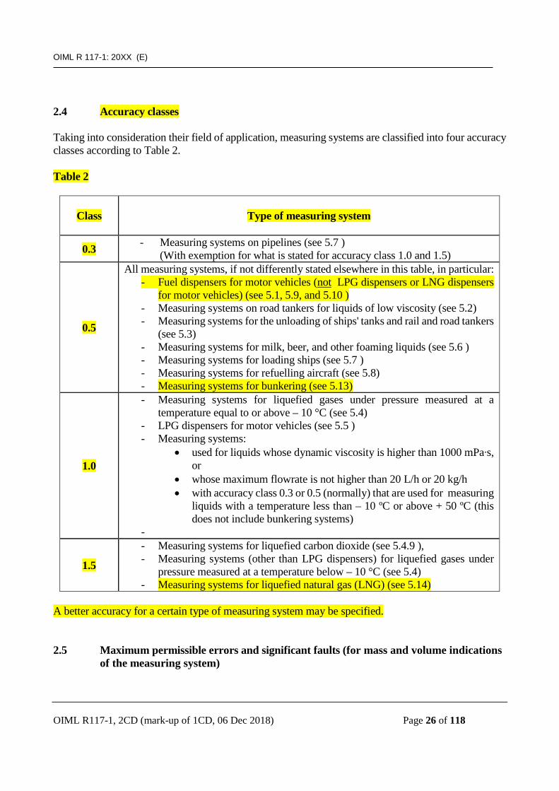
2.4 Accuracy classes Taking into consideration their field of application, measuring systems are classified into four accuracy classes according to Table 2. Table 2
Class
Type of measuring system
0.3 - Measuring systems on pipelines (see 5.7 ) (With exemption for what is stated for accuracy class 1.0 and 1.5)
0.5
All measuring systems, if not differently stated elsewhere in this table, in particular: - Fuel dispensers for motor vehicles (not LPG dispensers or LNG dispensers
for motor vehicles) (see 5.1, 5.9, and 5.10 ) - Measuring systems on road tankers for liquids of low viscosity (see 5.2) - Measuring systems for the unloading of ships' tanks and rail and road tankers
(see 5.3) - Measuring systems for milk, beer, and other foaming liquids (see 5.6 ) - Measuring systems for loading ships (see 5.7 ) - Measuring systems for refuelling aircraft (see 5.8) - Measuring systems for bunkering (see 5.13)
1.0
- Measuring systems for liquefied gases under pressure measured at a temperature equal to or above – 10 °C (see 5.4)
- LPG dispensers for motor vehicles (see 5.5 ) - Measuring systems:
• used for liquids whose dynamic viscosity is higher than 1000 mPa∙s, or
• whose maximum flowrate is not higher than 20 L/h or 20 kg/h • with accuracy class 0.3 or 0.5 (normally) that are used for measuring
liquids with a temperature less than – 10 ºC or above + 50 ºC (this does not include bunkering systems)
-
1.5
- Measuring systems for liquefied carbon dioxide (see 5.4.9 ), - Measuring systems (other than LPG dispensers) for liquefied gases under
pressure measured at a temperature below – 10 °C (see 5.4) - Measuring systems for liquefied natural gas (LNG) (see 5.14)
A better accuracy for a certain type of measuring system may be specified.
2.5 Maximum permissible errors and significant faults (for mass and volume indications
of the measuring system)

OIML R 117-1: 20XX (E)
OIML R117-1, 2CD (mark-up of 1CD, 06 Dec 2018) Page 27 of 118
2.5.1 For quantities not smaller than two litres (2 L) or two kilograms (2 kg), and without prejudice to 2.5.3, the maximum permissible errors, positive or negative, on quantity indications (volume at metering conditions, volume at base conditions and/or mass) are specified in Table 3. Table 3
Accuracy class Line 0.3 0.5 1.0 1.5
A (*) 0.3 % 0.5 % 1.0 % 1.5 % B (*) 0.2 % 0.3 % 0.6 % 1.0 % C (equal to Line A – Line B)
0.1 %
0.2 %
0.4 %
0.5 %
(*) see 2.6 for application of line A (measuring system)or line B (meter). 2.5.2 For quantities smaller than 2 L or 2 kg, and without prejudice to 2.5.3, the maximum permissible errors, positive or negative, on quantity indications (volume at metering conditions, volume at base conditions and/or mass) are specified in Table 4. Table 4
Measured quantity Maximum permissible errors from 1 to 2 L or kg value fixed in Table 3, applied to 2 L or kg from 0.4 to 1 L or kg twice the value fixed in Table 3 (applied to MMQ for Emin calculation) from 0.2 to 0.4 L or kg twice the value fixed in Table 3, applied to 0.4 L or kg from 0.1 to 0.2 L or kg
quadruple the value fixed in Table 3 (applied to MMQ for Emin calculation)
less than 0.1 L or kg quadruple the value fixed in Table 3, applied to 0.1 L or kg
The maximum permissible errors in Table 4 are related to line A or line B of Table 3 according to the requirements of 2.6 2.5.3 Whatever the measured quantity may be, the magnitude of the maximum permissible error is given by the greater of the following two values:
• the absolute (positive) value of the maximum permissible error given in Table 3 or Table 4, or • the minimum specified quantity deviation, (Emin).
For minimum measured quantities greater than or equal to 2 L or 2 kg, the minimum specified quantity deviation (Emin) is given by the following formulas:
• Formula for the measuring system:
Emin = (2 MMQ) × (A/100)

OIML R 117-1: 20XX (E)
OIML R117-1, 2CD (mark-up of 1CD, 06 Dec 2018) Page 28 of 118
where: MMQ is the minimum measured quantity (volume or mass), A is the numerical value specified in line A of Table 3 for the relevant accuracy class.
For MMQ less than 2 L or 2 kg Emin is twice the value specified in Table 4, and related to line A of Table 3.
• Formula for the meter or measuring device:
Emin = (2 MMQ) × (B/100)
where: MMQ is the minimum measured quantity (volume or mass), B is the numerical value specified in line B of Table 3 for the relevant accuracy class.
For MMQ less than 2 L or 2 kg Emin is twice the value specified in Table 4, and related to line B of Table 3.
Note: Emin is an absolute maximum permissible error. 2.5.4 A significant fault is a fault greater than the larger of these two values:
• one fifth of the absolute value of the maximum permissible error for the measured quantity; or • the minimum specified quantity deviation (Emin) for the measuring system.
2.6 Conditions for applying maximum permissible errors Provisions in this section apply to quantity indications at metering conditions (see 2.7 for converted indications). 2.6.1 Maximum permissible errors in line A of Table 3 apply to complete measuring systems, under rated operating conditions, without any adjustment between the various tests, for:
• type evaluation, • initial verification, • subsequent verifications.
Note: If the meter is provided with an adjustment or correction device, for type approval, it is
sufficient to verify that the error curve(s) is (are) within a range of two times the value specified in line A of Table 3.
2.6.2 Maximum permissible errors in line B of Table 3 apply to:
• type approval of a meter, under rated operating conditions, and • verification of the meter before the initial verification of the measuring system.
OIML R 117-1: 20XX (E)
OIML R117-1, 2CD (mark-up of 1CD, 06 Dec 2018) Page 29 of 118
If the meter is provided with an adjustment or correction device, it is sufficient to verify that the error curve(s) is (are) within a range of two times the value specified in line B of Table 3 during type approval. The meter may be able to measure various liquids either by using a particular adjustment for each liquid or by having the same adjustment for all the various liquids. In any case, the type approval certificate shall provide appropriate information on the capability of the meter. 2.6.3 When stated in the type approval certificate, the initial verification of a measuring system intended to measure two or more liquids may be carried out with one liquid only or with a liquid different from the intended liquid(s). In this case and if necessary, the type approval certificate provides information concerning the maximum permissible errors to be applied, so that 2.6.1 is fulfilled by the measuring system for all intended liquids. If a meter is initially verified in two stages (as per 6.2.1) and when stated in the type approval certificate, the verification of a meter intended to measure two or more liquids may be carried out with one liquid only or with a liquid different from the intended liquid(s). In this case and if necessary, the type approval certificate provides information concerning the maximum permissible errors to be applied, so that 2.6.2 is fulfilled by the meter for all intended liquids. The above considerations may be extended to the case of a measuring system or a meter intended to measure only one liquid but verified with another liquid. 2.7 Provisions for converted indications There are two approaches to verify a conversion device: The first approach verifies the conversion device with the associated measuring devices, the calculator, and the indicating device (together). This approach applies to mechanical conversion devices and may apply to electronic conversion devices. The second approach allows for separate verification of the individual components of a conversion device. This approach allows the separate verification of associated measuring sensors, associated measuring devices (made up of an associated measuring sensor plus an associated measuring transducer), and the conversion function. In both of these approaches, for the purpose of the verification, the indication of the quantity at metering conditions is assumed to be without any error. The approach to be applied shall be specified by the applicant for type approval. 2.7.1 First approach: Verification of a conversion device with the associated measuring devices, the calculator, and the indicating device (together)

OIML R 117-1: 20XX (E)
OIML R117-1, 2CD (mark-up of 1CD, 06 Dec 2018) Page 30 of 118
2.7.1.1 It is not mandatory that a conversion device indicates the quantities measured by the associated measuring devices (such as temperature, pressure, and density). 2.7.1.2 When a conversion device is verified using the first approach, the MPE allowable on the converted indication due to the conversion device (positive or negative), is the greater of:
• the value specified in line C of Table 3, or • one half of the minimum specified quantity deviation (Emin).
2.7.1.3 The value of a significant fault on converted indications (from 2.5.4) is the greater of:
• one fifth of the absolute value of the MPE for the measured quantity, or • the minimum specified quantity deviation (Emin).
2.7.2 Second approach: Verification of the individual components of the conversion device 2.7.2.1 Verification of a conversion device (as part of the calculator with its indicating device), using simulated inputs 2.7.2.1.1 Using digital input signals: when a calculator with its indicating device is verified separately, using known “digital input signals” to simulate inputs from associated measuring devices, the MPE and the significant fault for the indication of the temperature or pressure or density are restricted to rounding errors. 2.7.2.1.2 Using analog input signals: when a calculator with its indicating device is verified separately, using known “analog input signals” to simulate inputs from associated measuring devices, the MPE and the significant fault for the indication of the temperature or pressure or density are those specified in Table 5.1.

OIML R 117-1: 20XX (E)
OIML R117-1, 2CD (mark-up of 1CD, 06 Dec 2018) Page 31 of 118
Table 5.1 MPE for indication of characteristic quantities with known simulated analog inputs Maximum permissible
errors (MPE), and significant faults,
on measuring:
Accuracy class of the measuring system
0.3 0.5 1.0 1.5 Temperature ± 0.18 °C ± 0.30 °C Pressure
Less than 1 MPa : ± 30 kPa Between 1 MPa and 4 MPa : ± 3 %
More than 4 MPa : ± 120 kPa Density (mass to volume conversion) ± 0.6 kg/m3 ± 1.2 kg/m3
Density (temp. or pressure conversion) ± 3 kg/m3
Note: See 3.7.6 for determination of the size of scale intervals on associated measuring devices. 2.7.2.1.3 Verification of indications of converted quantities using simulated inputs The indication of the converted quantity shall agree with the “true value”, within one tenth of the MPE stated in line A of Table 3 for the applicable accuracy class. The “true value” is calculated based on the quantities indicated for the simulated inputs for the following:
• the unconverted quantity, • the temperature or pressure or density as determined by associated measuring devices,
as well as: • any characteristic quantities entered into the calculator (typically density), and • appropriate values from applicable International Recommendations and Standards.
2.7.2.2 Verification of associated measuring devices or associated measuring sensors 2.7.2.2.1 The MPE and significant fault for indications of temperature or pressure or density measured by an associated measuring device (which is made up of an associated measuring sensor and an associated measuring transducer) when it is subjected to a known temperature or pressure or density, are those specified in Table 5.2. If the indication is provided by the conversion device (as part of the calculator with its indicating device), this MPE includes the MPE of the corresponding calculator as specified in 2.7.2.1.1. 2.7.2.2.2 When an associated measuring device, which provides a digital signal output is verified by subjecting it to a known temperature or pressure or density, the MPE and significant fault are those specified in Table 5.2. The rounding errors of the calculator or other indicting device are assumed to be negligible.

OIML R 117-1: 20XX (E)
OIML R117-1, 2CD (mark-up of 1CD, 06 Dec 2018) Page 32 of 118
2.7.2.2.3 When an associated measuring sensor (which provides an analog output) is verified separately by subjecting it to a known temperature or pressure or density, the MPE and significant fault are those specified in Table 5.3. Table 5.2 MPE for associated measuring device indications Maximum permissible
errors (MPE), and Significant faults, on
measuring:
Accuracy class of the measuring system
0.3 0.5 1.0 1.5 Temperature ± 0.30 °C ± 0.50 °C Pressure
Less than 1 MPa : ± 50 kPa Between 1 MPa and 4 MPa : ± 5 %
More than 4 MPa : ± 200 kPa Density (mass to volume conversion) ± 1.0 kg/m3 ± 2.0 kg/m3
Density (temp. or pressure conversion) ± 5 kg/m3
Note: See 3.7.6 for determination of the size of scale intervals on associated measuring devices. Table 5.3 MPE for the output signal of the associated measuring sensorsMaximum permissible
errors (MPE), and Significant faults, on
measuring:
Accuracy class of the measuring system
0.3 0.5 1.0 1.5 Temperature ± 0.24 °C ± 0.40 °C Pressure
Less than 1 MPa : ± 40 kPa Between 1 MPa and 4 MPa : ± 4 %
More than 4 MPa : ± 160 kPa Density (mass to volume conversion) ± 0.8 kg/m3 ± 1.6 kg/m3
Density (temp. or pressure conversion) ± 4 kg/m3
Note: See 3.7.6 for determination of the size of scale intervals on associated measuring devices.

OIML R 117-1: 20XX (E)
OIML R117-1, 2CD (mark-up of 1CD, 06 Dec 2018) Page 33 of 118
2.8 Maximum permissible errors and significant faults on calculators Maximum permissible errors and significant faults on quantities of liquid indications applicable to calculators, positive or negative, when they are tested separately, are equal to one-tenth of the maximum permissible error defined in line A of Table 3. However, the magnitude of the maximum permissible error, respectively significant fault, shall not be less than one half of the scale interval of the measuring system in which the calculator is intended to be included. 2.9 Indications 2.9.1 The volume shall be indicated in cubic centimetres or millilitres, in cubic decimetres or litres, or in cubic metres. The mass shall be indicated in grams, kilograms, or metric tons (tonnes). The name of the unit or its symbol shall appear in the immediate vicinity of the indication. For mass, according to the case, the name of the unit or its symbol shall be accompanied by the term “mass” (actual mass) or “conventional mass” (comparison to weights). Where units of quantity are delivered by associated measuring instruments: temperature shall be indicated in degrees Celsius or in degrees Kelvin, density shall be indicated in kilograms per cubic meter, and pressure shall be indicated in bars or Pascals (Pa, kPa, MPa). If units of measurement outside the SI are required by a country’s national regulations, these units of measurement shall be considered acceptable for indications in that country. In international trade, the officially agreed equivalents between these units of measurement and those of the SI shall be applied. 2.9.2 Measuring systems shall be provided with an indicating device giving the quantity of liquid measured at metering conditions.
When a measuring system is fitted with a conversion device, it shall be possible to indicate the quantity at metering conditions and the converted quantity. In case of systems used for direct selling to the public, only the quantity used in the transaction shall be indicated in normal operation. The use of the same display for the indications of quantities at metering conditions and converted indications is permitted provided that the nature of the displayed quantity is clear and that these indications are available on request (See also Annex B). Provisions applicable to devices which indicate the quantity at metering conditions apply to devices which indicate the converted quantities by analogy.

OIML R 117-1: 20XX (E)
OIML R117-1, 2CD (mark-up of 1CD, 06 Dec 2018) Page 34 of 118
2.9.3 A measuring system may have several devices indicating the same quantity. Each shall meet the requirements of this Recommendation. Scale intervals of the various indications may be different. 2.9.4 For any measured quantity relating to the same measurement, the indications provided by various devices shall not deviate one from another by more than one scale interval or the greatest of the two scale intervals if they differ, except otherwise provided in clause 5 (see 5.10.1.3). For totalizers, this requirement applies to the difference in indication before and after the measurement. 2.9.5 Subject to specific provisions for certain types of measuring systems, use of the same indicating device for the indications of several measuring systems (which then have a common indicating device) is permitted provided that one of the following conditions is met:
• it is impossible to use any two of these measuring systems simultaneously, • the indications relating to a given measuring system are accompanied by a clear identification
of that measuring system, and the user may obtain the indication corresponding to any of the measuring systems concerned, using a simple command.
2.10 Elimination of air or gases 2.10.1 General requirements Measuring systems shall incorporate a gas elimination device for the proper elimination of any air or undissolved gases which may be contained in the liquid before it enters the meter. In the case that neither air intake nor gas release will occur in the liquid upstream of the meter, a gas elimination device is not required. The gas elimination device shall be suitable for the supply conditions and be arranged in such a way that the effect due to the influence of the air or gases on the measuring result does not exceed:
• 1 % of the quantity measured for milk, beer, other foaming potable liquids, and for liquids of a viscosity exceeding 1 mPa∙s (at 20 °C); or
• 0.5 % of the quantity measured for all other liquids.
However, it is not necessary for this effect to be less than 1 % of the minimum measured quantity. The values specified in this section apply to the difference between:
• the meter errors with air intake or with gas, and • the meter errors without air intake or gas.
Gas elimination devices shall be installed in accordance with the manufacturer’s instructions.
OIML R 117-1: 20XX (E)
OIML R117-1, 2CD (mark-up of 1CD, 06 Dec 2018) Page 35 of 118
2.10.2 Pumped flow (See also Annex B) A gas separator shall be provided when, without prejudice of requirements in 2.10.4, the pressure at the pump inlet may, even momentarily, fall below either the atmospheric pressure or the saturated vapor pressure of the liquid, which can result in mixed air or gas. If gaseous formations such as pockets liable to have a specific effect greater than 1 % of the minimum measured quantity can occur as well, this gas separator shall also be approved as a gas extractor. Depending on the supply conditions, a special gas extractor can be used for that purpose if the risk of mixed air or gas is smaller than 5 % of the volume delivered at the maximum flowrate. When applying this provision concerning gaseous formations, it is important to consider that:
• gaseous formations in the form of air pockets can occur because of thermal contraction during shutdown periods, and
• entrained gas and/or air pockets are likely to be introduced into the pipework when the supply tank becomes empty.
A gas extractor is required when the pressure at the pump inlet is always greater than the atmospheric pressure and the saturated vapor pressure of the liquid, but gaseous formations liable to have a specific effect greater than 1 % of the minimum measured quantity can occur. When applying this provision, it is necessary to consider the situations concerning gaseous formations that were mentioned above. No gas elimination device is required if the pressure at the pump inlet is always greater than the atmospheric pressure and the saturated vapor pressure of the liquid, and if any gaseous formation liable to have a specific effect greater than 1 % of the minimum measured quantity cannot form or enter the inlet pipework of the meter, whatever the conditions of use. If the gas elimination device is installed below the level of the meter, a non-return valve shall be incorporated to prevent the pipework between the two components from emptying. The loss of pressure caused by the flow of liquid between the gas elimination device and the meter shall be as small as possible. If the pipework upstream of the meter incorporates several high points, it may be necessary to provide one or more automatic or manual evacuation devices. 2.10.3 Non-pumped flow When a meter is supplied by gravity without use of a pump, and if the pressure of the liquid in all parts of the pipework upstream of the meter and in the meter itself is greater than the saturated vapor pressure of the liquid and the atmospheric pressure at metering conditions, a gas elimination device is not necessary.

OIML R 117-1: 20XX (E)
OIML R117-1, 2CD (mark-up of 1CD, 06 Dec 2018) Page 36 of 118
If the pressure of the liquid is likely to be lower than the atmospheric pressure while remaining greater than the saturated vapor pressure, an appropriate automatic device shall prevent entry of air into the meter. In other cases, an appropriate gas elimination device shall be provided. If a meter is supplied under gas pressure, the measuring system shall be so constructed that release of gas dissolved in the liquid is avoided. An appropriate device shall prevent entry of gas into the meter. In all circumstances, the pressure of the liquid between the meter and the transfer point shall be greater than the saturated vapor pressure of the liquid. 2.10.4 Viscous liquids 2.10.4.1 Viscous liquids – general requirements (for measuring systems for bunkering see 2.10.4.2) Since the effectiveness of gas elimination devices decreases as the viscosity of the liquids increases, these devices are not required for measuring liquids with a dynamic viscosity of more than 20 mPa∙s at 20 °C. In this case, it is necessary to make provisions to prevent entry of air. The pump shall be so arranged that the inlet pressure is always greater than the atmospheric pressure. If it is not always possible to meet this condition, a device shall be provided to stop the flow of liquid automatically as soon as the inlet pressure falls below the atmospheric pressure. A pressure gauge shall be used to monitor this pressure. These provisions are not necessary if devices are provided which ensure that no air can enter through the joints in the sections of the pipework under reduced pressure and if the measuring system is so arranged that no air or dissolved gases will be released.

OIML R 117-1: 20XX (E)
OIML R117-1, 2CD (mark-up of 1CD, 06 Dec 2018) Page 37 of 118
2.10.4.2 Viscous liquids – special requirements applicable to measuring systems for bunkering (see also Section 5.13) Clause 2.10.1 is not applicable to measuring systems for bunkering. Since the effectiveness of gas elimination devices decreases as the viscosity of the liquids increases, these devices are not required for measuring liquids with a dynamic viscosity of more than 20 mPa∙s at 20 °C.
Note: On measuring systems for bunkering (especially for the dynamic measurement of bunker fuel), the use of a gas elimination device is not required if the presence of air can be detected and corrected by the system to ensure that the required MPE is met.
Measuring systems on bunkering systems, even when measuring very high viscosity liquids and regardless of the presence of air, shall continue to meet the requirements of 2.4 to 2.6 with respect to the maximum permissible errors and the accuracy class of the measuring system. 2.10.5 Gas removal pipe The gas removal pipe of a gas elimination device shall not include a manually-controlled valve. However, if such a closing element is required for safety reasons, it shall be possible to ensure that the valve remains in the open position during operation by means of a sealing device or by means of a system interlock that would prevent further measurement upon valve closure. 2.10.6 Anti-swirl device If the supply tank of a measuring system is normally to be completely emptied, the outlet of the tank shall be fitted with an anti-swirl device, unless the measuring system incorporates a gas separator.
2.10.7 General provisions for gas elimination devices 2.10.7.1 The gas separated in a gas elimination device shall be evacuated automatically unless a device is provided which automatically either stops or sufficiently reduces the flow of liquid when there is a risk of air or gases entering the meter. In the case of shutdown, no measurement shall be possible unless the air or gases are automatically or manually eliminated. 2.10.7.2 The operational limits of a gas elimination device are as follows:
• the maximum flowrate(s) for one or more specified liquids, • the maximum pressure (with no flow running) and minimum pressure (with liquid and without
air intake while the pump is running at maximum flowrate) compatible with the correct operation of the gas elimination device, and
• the minimum measured quantity for which it is designed.

OIML R 117-1: 20XX (E)
OIML R117-1, 2CD (mark-up of 1CD, 06 Dec 2018) Page 38 of 118
2.10.8 Special provisions applicable to gas separators
Within the error limits specified in 2.10.1, a gas separator shall ensure the elimination of air or gases mixed with the liquid. A gas separator designed for a maximum flowrate lower than or equal to 20 m3/h shall ensure the elimination of any proportion by volume of air or gases relative to the measured liquid. A gas separator designed for a maximum flowrate higher than 20 m3/h shall ensure the elimination of 30 % air or gases relative to the measured liquid (the volumes of air or gases are measured at atmospheric pressure in determining their percentages). The percentage is considered only when the meter is running at flow rates higher than the minimum flow rate (mean value during one minute).
Note: Gas separators for flow rates up to 20 m3/h are therefore of relatively larger size than those for higher flow rates.
Furthermore, when provided, the automatic gas elimination device must continue to operate at the maximum pressure fixed for the gas separator.

OIML R 117-1: 20XX (E)
OIML R117-1, 2CD (mark-up of 1CD, 06 Dec 2018) Page 39 of 118
2.10.9 Special provisions applicable to gas extractors A gas extractor shall, at the maximum flowrate of the measuring system, ensure the elimination of an air or gas pocket of a volume (measured at atmospheric pressure) at least equal to the minimum measured quantity with no resulting additional effect greater than 1 % of the minimum measured quantity. A special gas extractor (capable of eliminating mixed gas and gas pockets), shall also be capable, at the system's maximum flowrate, of continuously separating a volume of air or gas mixed with the liquid equal to 5 % of the volume of liquid delivered (at the maximum flowrate) without the resulting additional effect exceeding the limits fixed in 2.10.1. 2.11 Gas indicator For certain types of measuring systems a gas indicator may be required. The gas indicator shall be designed so as to provide a satisfactory indication of the presence of air or gases in the liquid. The gas indicator shall be downstream of the meter. In empty hose measuring systems, the gas indicator may be in the form of a weir-type sight glass and may also be used as the transfer point. The gas indicator may be fitted with a bleed screw or with any other venting device when it forms a high point of the pipework. No pipe shall be connected to the venting device. Flow indicating devices (e.g. spinners) may be incorporated in gas indicators provided that such devices do not prevent observation of any gaseous formations which could be present in the liquid. 2.12 Transfer point 2.12.1 Measuring systems shall incorporate a minimum of one transfer point. This transfer point is located downstream of the meter in delivery systems and upstream of the meter in receiving systems. 2.12.2 Measuring systems may be of two types: "empty hose" systems and "full hose" systems. The term "hose" includes rigid pipework. 2.12.2.1 In case of an empty hose system the transfer point may be in the form of either a weir-type sight glass, or a closing device combined, in each case, with a system which ensures the emptying of the delivery hose after each measuring operation. 2.12.2.2 When, in case of full hose systems, the delivery line has a free end, the closing device must be installed as close as possible to this end. 2.12.2.3 In the case of receiving equipment, the same provisions apply by analogy to the reception pipework upstream of the meter.
OIML R 117-1: 20XX (E)
OIML R117-1, 2CD (mark-up of 1CD, 06 Dec 2018) Page 40 of 118
2.12.2.4 Measuring systems for bunkering (5.13) and measuring systems for LNG (5.14) may in different instances actually have piping/hose that is “partially filled.” The manufacturer shall provide documentation that explains how this is corrected in the measurement.
2.13 Complete filling of the measuring system 2.13.1 The meter and the pipework between the meter and the transfer point shall be kept full of liquid during measurement and during shutdown periods. When this condition is not met, especially in the case of fixed installations, the complete filling of the measuring system up to the transfer point shall be effected manually or automatically and shall be monitored during measurement and shutdowns. To ensure complete elimination of air and gases from the measuring system, a venting device (with means for visual or automatic detection of the complete filling) shall be placed in appropriate positions. 2.13.2 The effect of contraction due to temperature change on the liquid in the pipework between the meter and the transfer point shall not be greater than 1 % of the minimum measured quantity due to variations in temperature, equal to:
• 10 °C for exposed pipes, • 2 °C for insulated or underground pipes.
To calculate this additional effect the coefficient of thermal expansion for the liquid shall be rounded to 1 × 10⁻³ per degree Celsius. 2.13.3 Following the provisions in 2.10.3, a pressure maintaining device shall, if necessary, be installed downstream of the meter to ensure that the pressure in the gas elimination device and in the meter is always greater than both the atmospheric pressure and the saturated vapor pressure of the liquid. 2.13.4 When reversal of the flow could result in errors greater than the minimum specified quantity deviation, a measuring system (in which the liquid could flow in the opposite direction when the pump is stopped) shall be provided with a non-return valve. If necessary, the system shall also be fitted with a pressure limiting device. System shall either prevent reverse flow or accurately account for reverse flow by appropriate means. 2.13.5 In empty hose measuring systems, the pipework downstream of the meter and, if necessary, the pipework upstream of the meter shall have a high point so that all parts of the measuring system except the hose, always remain full. 2.13.6 In full hose measuring systems which are used for measuring liquids other than liquefied gases, the free end of the hose shall incorporate a device which prevents the draining of the hose during shutdown periods.

OIML R 117-1: 20XX (E)
OIML R117-1, 2CD (mark-up of 1CD, 06 Dec 2018) Page 41 of 118
When a closing device is installed downstream of this device, the volume of the space between them shall be as small as possible and, in all cases, be less than the minimum specified quantity deviation. 2.13.7 If the hose comprises several components, these shall be assembled either by means of a special connector which keeps the hose full, or by a connection system which is either sealed or requires the use of a special tool to be disconnected. 2.14 Emptying of the delivery hose In empty hose measuring systems, emptying of the delivery hose referred to in 2.12.2.1 is ensured by a venting valve. In some cases, this valve may be replaced by an active means, such as an auxiliary pump or compressed gas injector. This active device shall operate automatically. However, when it is not possible, for duly established technical or safety reasons, to deliver (or to receive) the measured quantity contained in hoses of an empty hose measuring system (for example when measuring liquefied carbon dioxide), this quantity shall be smaller than or equal to half the minimum specified quantity deviation. 2.15 Variations in the internal volume of full hoses For full hoses in a measuring system provided with a hose reel, the increase in internal volume due to the change from the coiled hose position when not under pressure to the uncoiled hose position when under pressure without any flow of liquid, shall not exceed twice the minimum specified quantity deviation. If the measuring system is not provided with a hose reel, the increase in internal volume shall not exceed the minimum specified quantity deviation. 2.16 Branches and bypasses 2.16.1 In measuring systems intended to deliver liquids, no means shall be provided by which any measured liquid can be diverted downstream of the meter. However, two or more delivery outlets may be permanently installed and operated simultaneously or alternately provided so that any diversion of flow to other than the intended receiving receptacle(s) cannot be readily accomplished or is readily apparent. Such means include, for example, physical barriers, visible valves or indications that make it clear which outlets are in operation, and explanatory signs, if necessary. For measuring systems intended to receive liquids, such provisions apply by analogy. A manually controlled outlet may be available for purging or draining the measuring system. Effective means shall be provided to prevent the passage of liquid through any such outlet during normal operation of the measuring system.

OIML R 117-1: 20XX (E)
OIML R117-1, 2CD (mark-up of 1CD, 06 Dec 2018) Page 42 of 118
For purposes of safety, a pressure relief valve could be installed downstream of the meter. In such an installation, it is required that indications make clear when the relief valve is in operation. 2.16.2 In measuring systems which may operate either with an empty hose or with a full hose and which are equipped with flexible pipes, a non-return valve shall be incorporated in the rigid pipework leading to the full hose immediately downstream from the selector valve. In addition, the selector valve shall not, in any position, permit connection of the discharge hose, operating as an empty hose to the pipework leading to the full hose. 2.16.3 It shall not be possible to bypass the meter. (See also note in Annex B).
Note: In certain cases where a bypass does exist (such as for cooling the system), effective means shall be provided to prevent the passage of liquid through any such bypass during normal operation of the measuring system.
2.17 Control and closing mechanisms 2.17.1 If there is a risk that the supply conditions can overload the meter, a flow limiting device shall be provided. This device shall be installed downstream of the meter (solution “A”). It shall be possible to seal it. An alternative solution “B” by software is also acceptable (eg: software to stop the flow if the flowrate exceeds meter limits). This technical choice must be described by the manufacturer. 2.17.2 The various positions of the controls of multi-way valves shall be easily visible and located by notches, stops or other fixing devices. Deviations from this requirement are permissible when the adjacent positions of the controls form an angle of 90º or more. 2.18 Various provisions 2.18.1 If provided, filters shall not disturb the accuracy or operation of the measuring system or its components. 2.18.2 In the case of measuring liquid petroleum products, means for vapor recovery shall not influence the accuracy of measurements such that the maximum permissible error is exceeded. 2.18.3 It may be possible in meters for liquid food (for example, milk) to dismount and disassemble the measuring device to the extent necessary for cleaning. The measuring device must be designed such that improper assembly of the components of the measuring device is not possible. Instead, the meters may be provided with assembly instructions or marks that will ensure correct measurements. Dismounting the measuring device shall not provide the ability to change the accuracy of the device, and in particular, it shall not provide access to sealed parameters or other adjustment means. 2.19 Markings

OIML R 117-1: 20XX (E)
OIML R117-1, 2CD (mark-up of 1CD, 06 Dec 2018) Page 43 of 118
2.19.1 Each measuring system shall bear the following information: • type approval number, • manufacturer's identification mark, trademark or name, • designation selected by the manufacturer, if appropriate, • year of manufacture, • serial number, • characteristics as defined in 2.3.1 (measuring system), 3.1.1.1 (meter), or 2.10.7.2 (gas
elimination device), • accuracy class, and • verification marks.
This information shall be put on one or several data plates on a part not likely to be removed in normal conditions of use. At least the information related to the minimum measured quantity and the verification marks shall be visible in normal conditions of use. The information marked on the measuring system shall be the information based on the type approval, including the temperature range of the liquid, and should not be confused with descriptions affixed for safety reasons, in particular the pressure limits. 2.19.2 Each component or sub-system for which type approval has been granted shall bear the following information:
• serial number, • type approval number.
This information shall be part of the component or sub-system itself or shall be put on a data plate not likely to be removed from the component or sub-system under normal conditions of use. 2.19.3 If several components operate in a single measurement system, the markings required for each part of the system may be combined on a single plate. If several separate measuring systems operate in a common housing, only one data plate is required. When a measuring system can be transported without being dismantled, the markings required for each component may also be combined on a single plate. 2.19.4 When volume at base conditions is indicated, the result of measurement shall be accompanied with information with respect to the base conditions, for example: “at 15 ºC” or “at 15 ºC and 101.325 kPa ”. 2.20 Sealing devices and stamping plate

OIML R 117-1: 20XX (E)
OIML R117-1, 2CD (mark-up of 1CD, 06 Dec 2018) Page 44 of 118
2.20.1 General Sealing may be carried out with metal, plastic or other suitable means as long as it is sufficiently durable and provides evidence of tampering The seals shall, in all cases, be easily accessible. Sealing shall be provided on all parts of the measuring system which cannot be materially protected in any other way against operations liable to affect the measurement accuracy. Without prejudice to the provisions in 3.1.4 and 3.7.5, it must be prohibited to change parameters which participate in the determination of the results of measurement (parameters for correction and conversion in particular) by means of sealing devices. A plate, referred to as the stamping plate, aimed at receiving the verification marks, shall be sealed or permanently attached on a support of the measuring system. It may be combined with the data plate of the measuring system referred to in 2.19. In the case of a measuring system used for potable liquids, sealing shall be applied such that the equipment may be dismantled for cleaning purposes. 2.20.2 Electronic sealing devices 2.20.2.1 When access to parameters that participate in the determination of results of measurement is not protected by mechanical sealing devices, the protection shall fulfil the provisions of 2.20.2.1.1 through 2.20.2.1.5. 2.20.2.1.1 Either:
• access shall only be allowed to authorized persons, e.g. by using a “password” and, after changing parameters, the measuring system may be put into use “in sealed condition” again without any restriction; or
• access is allowed without restrictions (similar to the classical sealing) but, after changing parameters, the measuring system shall only be put into use “in sealed condition” again by authorized persons, e.g. by using a “password”.
2.20.2.1.2 The “password” must be changeable. 2.20.2.1.3 In case of direct selling to the public, the use of only a “password” is not allowed and the measuring system shall be provided with a mechanical sealing device, e.g. access cover protected switch or key switch.

OIML R 117-1: 20XX (E)
OIML R117-1, 2CD (mark-up of 1CD, 06 Dec 2018) Page 45 of 118
2.20.2.1.4 When it is in the configuration mode (a mode in which parameters can be changed), the device shall either: not operate or clearly indicate that it is in the configuration mode. This status shall remain until the measuring system has been put into use “in sealed condition” in accordance with 2.20.2.1.1. 2.20.2.1.5 For identification, data concerning the latest intervention(s) shall be automatically recorded into an event logger. The record shall include at least:
• an event counter, • the date the parameter was changed (this is allowed to be entered manually), • the new value of the parameter, and • an identification of the person that implemented the intervention.
The traceability of the last intervention shall be assured for at least two years, if it is not over-written on the occasion of a further intervention. Given the current state of technology, it is strongly encouraged that the event logger store many more than just one intervention. If more than one intervention is stored, and if deletion of a previous intervention must occur to permit a new record, the oldest record shall be deleted. 2.20.2.2 For measuring systems with parts which may be disconnected one from another by the user and which are interchangeable, the following provisions shall be fulfilled:
• it shall not be possible to access parameters that participate in the determination of results of measurements through disconnected points unless the provisions in 2.20.2.1 are fulfilled;
• interposing any device which may influence the accuracy shall be prevented by means of electronic and data processing securities or, if not possible, by mechanical means.
2.20.2.3 For measuring systems with parts which may be disconnected one from another by the user and which are not interchangeable, the provisions in 2.20.2.2 apply. Moreover, these measuring systems shall be provided with devices which do not allow them to operate if the various parts are not associated according to the manufacturer's configuration. Note: Disconnections by the user which are not allowed may be prevented, for example by means
of a device that prevents any measurement after disconnecting and reconnecting. 2.21 Unattended delivery Measuring systems for unattended delivery (such as those for fuel delivery from road tankers into filling stations or for direct sale to the public) may be designed in such a way that the transaction is not settled when the supplier leaves the delivery location. This arrangement is only applicable when there is an existing agreement between the parties. National or regional regulations may require that measuring systems intended for unattended delivery are equipped with:

OIML R 117-1: 20XX (E)
OIML R117-1, 2CD (mark-up of 1CD, 06 Dec 2018) Page 46 of 118
• an automatic device to identify the unloading location; • a printing device for automatically issuing a receipt to the customer; and • a memory device in which the following data are recorded: identification of the measuring
system, measurement data, time and date of delivery, and the unloading location.
Conveners note: Previous Section 5.12 “Unattended delivery” was moved from Chapter 5 because it is NOT a measuring system and NOT part of a measuring system. It was decided to move this section into the General Requirements of Chapter 2, new Section 2.21.

OIML R 117-1: 20XX (E)
OIML R117-1, 2CD (mark-up of 1CD, 06 Dec 2018) Page 47 of 118
3 Requirements for meters and ancillary devices of a measuring system 3.1 Meter The meter(s) of a measuring system shall meet the following requirements, whether or not it (they) is (are) subject to a separate type approval: 3.1.1 Rated operating conditions 3.1.1.1 The rated operating conditions of a meter are determined at least by the following characteristics:
• minimum measured quantity, MMQ; • flowrate range limited by the minimum flowrate, Qmin, and the maximum flowrate, Qmax, (or by
the Reynolds number range, if applicable); • name or type of the liquid or its relevant characteristics, for example the viscosity range limited
by the minimum viscosity of the liquid and the maximum viscosity of the liquid and/or the density range limited by the minimum density of the liquid ρmin and the maximum density of the liquid ρmax ;
• the pressure range limited by the minimum pressure of the liquid, Pmin and the maximum pressure of the liquid, Pmax;
• the temperature range limited by the minimum temperature of the liquid, Tmin. and the maximum temperature of the liquid, Tmax;
• climatic and mechanical environmental class (see Annex A); • nominal value of the AC voltage supply and/or limits of DC voltage supply.
3.1.1.2 The value of the minimum measured quantity shall be in the form 1 × 10n, 2 × 10n or 5 × 10n authorized units of volume or mass, n being a positive or negative whole number, or zero. 3.1.2 Metrological requirements In this section, the requirements for a meter also apply to measuring devices (see 6.1.5).
3.1.2.1 The maximum permissible errors for a meter, under rated operating conditions, are equal to those specified in line B of Table 3. 3.1.2.2 For any quantity equal to or greater than five times the minimum measured quantity, the repeatability error of the meter shall not be higher than two-fifths of the value specified in line A of Table 3. 3.1.2.3 Under rated operating conditions for a given liquid, meters shall present a magnitude of the difference between the initial intrinsic error and the error after the endurance test equal to or less than the value specified in line B in Table 3.

OIML R 117-1: 20XX (E)
OIML R117-1, 2CD (mark-up of 1CD, 06 Dec 2018) Page 48 of 118
Note : The requirements concerning the endurance testing are found in Section 6.1.5 and R117-2. It should also be noted that the endurance test is only applicable to meters with moving parts and parts under mechanical stress (this means that Coriolis, ultrasonic, and electromagnetic meters are not required to undergo an endurance test).
3.1.2.4 The minimum specified quantity deviation (Emin) for the meter is given by the second formula in Section 2.5.3. 3.1.3 Adjustment device (See also Annex B) A meter may have a sealable means of adjustment which permits modification of the ratio between the indicated quantity and the actual quantity to be within:
• 0.05 % for meters intended for measuring systems with accuracy class 0.3; • 0.1 % for meters intended for measuring systems with all other accuracy classes.
An adjustment device shall only be used to reduce the errors to as close to zero as possible. Adjustment by means of a bypass of the meter is prohibited. 3.1.4 Correction device 3.1.4.1 Meters may be fitted with correction devices; such devices are always considered as an integral part of the meter. All requirements that apply to the meter, in particular the maximum permissible errors specified in 3.1.2.1, are therefore applicable to the corrected quantity (at metering conditions). Submitted type evaluation paperwork must state if the correction device is a mandatory part of the meter. 3.1.4.2 In normal operation, the non-corrected quantity shall not be displayed. The non-corrected quantity shall, however, be available for test purposes. 3.1.4.3 The correction device shall only be used to reduce the errors to as close to zero as possible. 3.1.4.4 All the parameters which are not measured and which are necessary for correcting shall be contained in the calculator or the meter at the beginning of the measurement operation. The type approval certificate may prescribe the possibility of checking parameters that are necessary for correctness at the time of verification of the correction device. 3.1.4.5 For transactions that involve direct selling to the public, applying a correction is allowed only by selecting the name or the type of the liquid at the beginning of the measurement operation.
For transactions that do not involve direct selling to the public, it is allowed to select or enter the name or type of the liquid or any other data, when this data participates in the correction of the quantity. This other allowed data is that which characterizes the name or type of the measured liquid without any ambiguity.

OIML R 117-1: 20XX (E)
OIML R117-1, 2CD (mark-up of 1CD, 06 Dec 2018) Page 49 of 118
All cases are subject to the following conditions: A printing device subject to legal metrological control is mandatory;
• This data and a note explaining that this data has been entered manually shall be printed at the same time as the measuring results;
• The name or type of the liquid shall be known and printed without any ambiguity. For transactions that do not involve direct selling to the public (especially transactions governed by specific contracts), a printing device is not required when the following conditions exist:
• when the correction is stored by a memory device accessible to all parties involved; or • when both parties have the possibility to be present to conclude the transaction, by any
appropriate means, and the two parties are informed of the conditions of the correction.
The type approval certificate may indicate how to gain access to the memorized data. 3.1.4.6 The correction device shall not allow the correction of a pre-estimated drift (such as in relation to time or total quantity). 3.1.4.7 The associated measuring devices, if any, shall comply with the applicable International Standards or Recommendations. Their accuracy shall be good enough to permit the requirements on the meter to be met, as specified in 3.1.2.1. 3.1.4.8 Associated measuring devices shall be fitted with checking facilities, as specified in 4.3.6. 3.1.5 Measuring systems equipped with turbine meters 3.1.5.1 The pressure downstream of the meter shall be such that cavitation is avoided. 3.1.5.2 If the accuracy of the meter is affected by disturbances in the upstream or downstream pipeline, the meter shall be provided with a sufficient number of straight pipe lengths, with or without flow straightening devices, as specified by the manufacturer, so that the indications of the installed measuring system including the meter meet the requirements of 2.4 to 2.6 with respect to the maximum permissible errors and according to the accuracy class of the measuring system. 3.1.5.3 The characteristics of the flow straightening devices, and/or straight pipe lengths, if required, shall be specified in the type approval certificate.

OIML R 117-1: 20XX (E)
OIML R117-1, 2CD (mark-up of 1CD, 06 Dec 2018) Page 50 of 118
3.1.5.4 If the system is provided with a programmable or adjustable “low-flow cut-off” feature, a “zero-offset adjustment” feature, or any other adjustable feature relied upon to comply with a test requirement throughout the rated operating conditions, the feature(s) shall be sealable. Clear instructions for the proper setting of the feature(s) shall be provided by the manufacturer. The limitations and setting of the feature(s) shall be detailed in the type approval certificate. “Low-flow cut-off” features shall not be set at flow rates higher than 20 % of the application-defined minimum flow rate. The error caused by the zero-offset of the meter, related to the minimum flowrate, shall not exceed the value specified in line C of Table 3. 3.1.6 Measuring systems equipped with electromagnetic meters 3.1.6.1 The requirements in 3.1.5.1 to 3.1.5.4 apply. 3.1.6.2 The rated operating conditions with respect to the conductivity of the liquid and the cable characteristics shall be specified by the manufacturer and shall be documented in the type approval certificate. 3.1.7 Measuring systems equipped with ultrasonic meters 3.1.7.1 The requirements in 3.1.5.1 to 3.1.5.4 apply. 3.1.7.2 The minimum Reynolds number of the liquid to be measured shall be specified by the manufacturer. 3.1.8 Measuring systems equipped with vortex meters 3.1.8.1 The requirements in 3.1.5.1 to 3.1.5.4 and the requirement in 3.1.7.2 apply. 3.1.9 Measuring systems equipped with mass flowmeters 3.1.9.1 The requirements in 3.1.5.1 to 3.1.5.4 apply. 3.1.9.2 The mass flowmeter shall be installed in the measuring system in accordance with the system manufacturer’s recommendations and with any conditions or limitations set out in the type approval certificate. 3.1.10 Measuring systems equipped with drum meters for alcohol

OIML R 117-1: 20XX (E)
OIML R117-1, 2CD (mark-up of 1CD, 06 Dec 2018) Page 51 of 118
3.1.10.1 The volume of the individual measuring chambers of the drum meter shall be 1 × 10n, 2 × 10n, or 5 × 10n litres, where n is a positive or negative whole number, or zero. The chambers of the drum shall be of equal size. The drum axis shall be horizontal. In order to be able to ensure that it is correctly installed, the meter shall be equipped with a level indicating device if, when the drum axis is inclined up to 3º to the horizontal, the indication of the meter varies by more than half the maximum permissible error on verification. 3.1.10.2 The volumes of the individual measuring chambers of a drum meter may be adjusted by means of displacement bodies. The associated conversion device which measures the density and the temperature of the measured liquid shall be adjustable. 3.1.10.3 The conversion device to determine the volume of ethanol belonging to a drum meter shall function in accordance with the International Recommendation OIML R 22 “International alcoholometric tables” (1975). The reference temperature for the alcohol measurement is 20 ºC. The conversion may be applied mechanically or electronically. These requirements also apply to other measuring principles. (See also Sections T.c.4 and 2.7). 3.1.10.4 The sampler of a drum meter shall automatically separate and collect a representative sample of the liquid to be measured in order to permit the separate determination of the average alcohol content of liquid which has passed through the measuring device, for example, by separating an equal volume each time the measuring chambers are filled. If the test volume withdrawn is subject to special or separate treatment, the measuring device shall be so adjusted that the volume withdrawn is not included in the indication of the drum meter. 3.1.10.5 The elimination of air intake or gas release will be performed by the drum meter itself. So no additional gas elimination device is required. 3.1.10.6 The following inadmissible operating conditions and failures of a drum meter shall either be prevented by special devices incorporated in the meter, or their occurrences shall be indicated by warning devices:
• excessive flowrate; • obstruction of free flow; • overfilling of the drum due to obstruction of the rotating elements; • temperature outside the permissible range; and • inadmissible heating of the separated sample.
3.2 Indicating device 3.2.1 General provisions

OIML R 117-1: 20XX (E)
OIML R117-1, 2CD (mark-up of 1CD, 06 Dec 2018) Page 52 of 118
3.2.1.1 Reading of the indications shall be precise, easy and non-ambiguous whatever position the indicating device comes to rest; if the device comprises several elements, it shall be arranged in such a way that the reading of the measured quantity can be made by simple juxtaposition of the indications of the different elements. The decimal sign shall appear distinctly. 3.2.1.2 The scale interval shall be in the form 1 × 10n, 2 × 10n or 5 × 10n authorized units of quantity, where n is a positive or negative whole number, or zero. 3.2.1.3 Non-significant minimum increments of registration should be avoided. This does not apply to price indications. 3.2.1.4 The scale interval shall satisfy the following requirements:
• for analog indicating devices, the quantity corresponding to 2 mm on the scale or to one-fifth of the scale interval (of the first element for mechanical indicating devices), whichever is greater, shall be less than or equal to the minimum specified quantity deviation;
• for digital indicating devices, the quantity corresponding to two minimum increments of registration shall be less than or equal to the minimum specified quantity deviation.
3.2.2 Mechanical indicating device 3.2.2.1 When the graduation of an element is entirely visible, the value of one revolution of that element shall be in the form 10n authorized units of quantity, where n is a whole number. This rule however, does not apply to the element corresponding to the maximum range of the indicating device. 3.2.2.2 On an indicating device having several elements, the value of each revolution of an element whose graduation is entirely visible must correspond to the scale interval of the following element. 3.2.2.3 An element of the indicating device may have continuous or discontinuous movement, but when elements other than the first have only part of their scales visible through the windows, these elements shall have discontinuous movement. 3.2.2.4 The advance by one figure of any element having discontinuous movement shall occur and be completed when the preceding element passes from 9 to 0. 3.2.2.5 When the first element has only a part of its scale visible through a window and has a continuous movement, the dimension of that window shall be at least equal to 1.5 times the distance between two consecutive graduated scale marks. 3.2.2.6 All scale marks shall have the same width, constant along the line and not exceeding one quarter of the scale spacing. The apparent scale spacing shall be equal to or greater than 2 mm. The apparent height of the figures shall be equal to or greater than 4 mm, unless otherwise specified in the requirements for particular measuring systems.

OIML R 117-1: 20XX (E)
OIML R117-1, 2CD (mark-up of 1CD, 06 Dec 2018) Page 53 of 118
3.2.3 Electronic indicating device The continuous display of quantity during the period of measurement is only mandatory in the case of direct selling to the public. However, if interrupting the display of quantity interrupts the action of some checking facilities that are mandatory or necessary to ensure correct measurement, the quantity passing through the meter during each interruption shall be smaller than or equal to the minimum measured quantity. If the device is capable of hiding a small number of "minimum increments of registration" at the beginning of a measurement, it must be possible during type approval and initial verification to easily switch off this feature. 3.2.4 Zero-setting device for the quantity indicating device 3.2.4.1 A quantity indicating device may be provided with an ancillary device for setting the indication to zero either by manual operation or by means of an automatic system. 3.2.4.2 Once the zeroing operation has begun, it shall be impossible for the quantity indicating device to show a result different from that of the measurement which has just been made, until the zeroing operation has been completed. Indicating devices on fuel dispensers and electronic measuring systems shall not be capable of being reset to zero during measurement. On other measuring systems, either this provision shall be fulfilled or a clearly visible notice shall be provided on the indicating device stating that this operation is prohibited. 3.2.4.3 On analog indicating devices, the residual indication after return to zero shall not be more than half the minimum specified quantity deviation. 3.2.4.4 On digital indicating devices, the quantity indication after return to zero shall be zero without any ambiguity. 3.2.4.5 In the case of direct selling to the public, and except for fuel dispensers, the following provisions apply:
• The next delivery shall be inhibited until the indicating device has been reset to zero; or • When the zeroing operation is not automatic, the measuring system shall bear legible and
indelible information inviting the customer to reset the indication before the delivery. 3.3 Price indicating device 3.3.1 A quantity indicating device with aligned figures and zero-setting may be complemented with a price indicating device, also with aligned figures and zero-setting.

OIML R 117-1: 20XX (E)
OIML R117-1, 2CD (mark-up of 1CD, 06 Dec 2018) Page 54 of 118
3.3.2 The unit price may be displayed before the delivery (3.3.2.1) or the unit price may be keyed in after the delivery (3.3.2.2). 3.3.2.1 The selected unit price shall be displayed by an indicating device before the start of the measurement (unless the option in 3.3.2.2 is used). The unit price shall be adjustable; changing the unit price may be carried out either directly on the measuring system or through ancillary devices. The indicated unit price at the start of the measurement operation shall be valid for the whole transaction. A new unit price shall only be effective at the moment of a new measurement operation. A time of at least 5 seconds shall elapse between indicating a new unit price and before the next measurement operation can start, if the unit price is set from ancillary devices. 3.3.2.2 (This section is a different option from 3.3.2.1 and is not applicable to fuel dispensers.) In the case of price indicating devices for measuring systems other than fuel dispensers, it is permitted to display only the quantity before and during the delivery. Neither unit price nor total price is displayed before and during the delivery. After the measurement operation is complete, the unit price is selected (or keyed in) to process the total price calculation to conclude the transaction; this unit price shall be valid for the whole transaction. In the case of direct selling to the public, the unit price shall be displayed or printed. 3.3.3 The provisions in 3.2 relating to quantity indicating devices apply also, by analogy, to the price indicating devices. 3.3.4 The monetary unit used, or its symbol, shall appear in the immediate vicinity of the indication. 3.3.5 The zero-setting devices of the price indicating device and of the quantity indicating device shall be designed in such a way that zeroing either indicating device automatically involves zeroing the other. 3.3.6 The scale interval shall satisfy the following requirements
• for analog indicating devices, the price corresponding to 2 mm on the scale or to one-fifth of the scale interval (of the first element for mechanical indicating devices), whichever is greater, shall be less than or equal to the minimum specified price deviation;
• for digital indicating devices, the price corresponding to two minimum increments of registration, shall be less than or equal to the minimum specified price deviation.
However, the interval of one-fifth of the scale interval or of 2 mm in the case of the first bullet or the scale interval in the case of the second bullet needs not correspond to a value less than that of the smallest coin in circulation in the country in which the equipment is used.

OIML R 117-1: 20XX (E)
OIML R117-1, 2CD (mark-up of 1CD, 06 Dec 2018) Page 55 of 118
3.3.7 The difference between the indicated price and the price calculated from the unit price and the indicated quantity shall not exceed the minimum specified price deviation. However, this difference need not be less than the smallest coin in circulation in the country in which the equipment is used. Moreover, this requirement does not apply when the unit price has been changed between two measurements. 3.3.8 The significant fault on price indication (the difference in 3.3.7) is the price corresponding to the significant fault for the quantity as specified in 2.5.4. 3.3.9 On analog indicating devices, the residual indication after zeroing shall not exceed half the minimum specified price deviation. However, this indication need not be less than the smallest coin in circulation in the country in which the equipment is used. 3.3.10 On digital indicating devices, the price indication after zeroing shall be zero without any ambiguity. 3.4 Printing device 3.4.1 The printed scale interval shall be in the form of 1 × 10n, 2 × 10n or 5 × 10n authorized units of quantity, n being a positive or negative whole number, or zero, and shall not be greater than the minimum specified quantity deviation. The printed scale interval shall not be less than the smallest scale interval of the indicating devices. 3.4.2 The quantity printed shall be expressed in one of the units authorized for the indication of quantity and expressed in the same units as the indicating device. The figures, the unit used or its symbol and the decimal sign, if any, shall be printed unambiguously on the ticket. 3.4.3 The printing device may also print information identifying the measurement such as: sequence number, date, identification of the dispenser, type or name of liquid, etc. If the printing device is connected to more than one measuring system, it shall print the identification of the relevant system. 3.4.4 If a printing device allows repetition of the printing before a new delivery has started, copies shall be clearly marked as such, for example by printing "duplicate". 3.4.5 If the quantity is determined by the difference between two printed values, even if one is expressed in zeros, it shall be impossible to withdraw the ticket from the printing device during measurement.

OIML R 117-1: 20XX (E)
OIML R117-1, 2CD (mark-up of 1CD, 06 Dec 2018) Page 56 of 118
3.4.6 Where the printing device and quantity indicating device each have a zeroing device, these devices shall be designed so that resetting one of them to zero also resets the other. 3.4.7 The printing device may print, in addition to the measured quantity, the corresponding transaction price, or this price accompanied by the unit price. Any value shall be printed as a repeated value from the measuring system. The figures, the monetary unit used or its symbol, and the decimal sign, if any, shall be printed unambiguously on the ticket. 3.4.8 The printed price scale interval shall be in the form 1 × 10n, 2 × 10n or 5 × 10n monetary units, n being a positive or negative whole number, or zero; it shall not exceed the minimum specified price deviation. However, it need not be less than the smallest coin in circulation in the country in which the equipment is used. 3.4.9 If the quantity indicating device is not fitted with a price indicating device, the difference between the printed price and the price calculated on the basis of the indicated quantity and the printed unit price shall comply with the requirements in 3.3.7. 3.4.10 Electronic printing devices are also subject to the requirements in 4.3.5. 3.5 Memory device 3.5.1 Measuring systems may be fitted with a memory device to store measurement results until their use or to keep a record of commercial transactions, providing proof in the event of a dispute. Devices used to read stored information are considered as included in the memory devices. It is not required that the parties interested in a transaction shall be provided continuously with the results of measurement, but only that they shall have access to these results (for example, in the event of a dispute). In addition, in the case of self-service (filling station, truck filling station) the owner of the measuring system is considered to have access to the indications of the measuring system even when he does not use this possibility in practice. 3.5.2 The medium on which data are stored must have sufficient permanency to ensure that the data are not corrupted under normal storage conditions. There shall be sufficient memory storage for any particular application. 3.5.3 Stored data may be deleted if either:
• the transaction is settled; or • these data are printed by a printing device subject to legal control.

OIML R 117-1: 20XX (E)
OIML R117-1, 2CD (mark-up of 1CD, 06 Dec 2018) Page 57 of 118
3.5.4 After the requirements in 3.5.3 are fulfilled and when the storage is full, it is permitted to delete memorized data when both the following conditions are met:
• data are deleted in the same order as the recording order and the rules established for the particular application are respected;
• deletion is carried out either automatically or after a special manual operation. 3.5.5 Memorization shall be such that it is impossible in normal use to modify stored values. The data memorized must be protected against unintentional and intentional changes with common software tools. 3.5.6 Memory devices shall be fitted with checking facilities according to 4.3.5. The aim of the checking facility is to ensure that stored data correspond to the data provided by the calculator and that restored data correspond to stored data. 3.6 Pre-setting device 3.6.1 The preset quantity shall be indicated before the start of the measurement. 3.6.2 Where pre-setting is effected by means of several controls which are independent of each other, the scale interval corresponding to one control shall be equal to the pre-setting range of the control of the next lower order. Pre-setting devices with push-buttons or similar means to pre-set fixed quantities are allowed, provided that these fixed quantities are equal to a whole number of units of volume or mass. 3.6.3 Pre-setting devices may be so arranged that the repetition of a selected quantity does not require a new setting of the controls. 3.6.4 Where it is possible to view simultaneously the figures of the display device of the pre-setting device and those of the quantity indicating device, the former shall be clearly distinguishable from the latter. 3.6.5 Indication of the selected quantity may, during measurement, either remain unaltered or return progressively to zero. However, for an electronic pre-setting device it is acceptable to indicate the preset value on the indicating device for quantity or price by means of a special operation with the restriction that this value shall be replaced by the zero indication for quantity or price before the measurement operation can start. 3.6.6 In the case of a prepaid or pre-ordered delivery:
• the difference found under normal operating conditions between the pre-set quantity and the quantity shown by the quantity indicating device at the end of the measurement operation shall not exceed the minimum specified quantity deviation;

OIML R 117-1: 20XX (E)
OIML R117-1, 2CD (mark-up of 1CD, 06 Dec 2018) Page 58 of 118
• the difference found under normal operating conditions between the prepaid amount and the price shown by the price indicating device at the end of the measurement operation shall not exceed the minimum specified price deviation.
3.6.7 The pre-set quantities and the quantities shown by the quantity indicating device shall be expressed in the same unit. This unit (or its symbol) shall be marked on the pre-setting mechanism. 3.6.8 The scale interval of the pre-setting device shall not be less than the scale interval of the indicating device. 3.6.9 Pre-setting devices may incorporate a device to permit the flow of liquid to be stopped quickly when necessary. 3.6.10 Measuring systems with a price indicating device may also be fitted with a price pre-setting device which stops the flow of the liquid when the quantity delivered corresponds to the pre-set price. The requirements in 3.6.1 to 3.6.9 apply by analogy. 3.7 Conversion device 3.7.1 Measuring systems may be fitted with a conversion device as defined in T.c.4. The provisions of 3.7 apply to electronic conversion devices and, by analogy, to mechanical conversion devices. 3.7.2 The calculation of the converted quantity shall be made according to the applicable International Recommendations or Standards, or other acceptable methods. 3.7.3 The parameters which characterize the measured liquid and which are employed in the conversion formula shall be measured using associated measuring devices subject to control when the parameters vary during the measurement process. However, some of these parameters may be not measured, or associated measuring devices may be not subject to control if these parameters do not vary substantially. In any case, the maximum permissible errors on converted indications due to the conversion device, shall not exceed the values specified in 2.7.1.2. 3.7.4 Associated measuring sensors and suitable provisions for testing shall be installed within a distance of one metre (1 m) of the meter wherever possible. Where this is not possible, it shall be possible to verify that the associated measuring devices are able to determine (within the maximum permissible errors as defined in Table 4.2) the relevant characteristic quantities of the liquid, as they exist in the measuring device (See also Annex B). The associated measuring devices shall not affect the correct functioning of the meter(s). 3.7.5 All the parameters which are not measured and which are necessary for the conversion shall be present in the calculator at the beginning of the measurement operation. It must be possible to print or to indicate them from the calculator. The device(s) used exclusively to print or indicate these non-
OIML R 117-1: 20XX (E)
OIML R117-1, 2CD (mark-up of 1CD, 06 Dec 2018) Page 59 of 118
measured parameters are considered to be non-critical and are only subject to tests showing their capability to correctly indicate or print these values. For a mechanical conversion device that cannot print or indicate these values, a seal must be broken to change any setting.
For direct selling to the public, it is allowed to enter the name or type of the liquid into the calculator at the beginning of the measurement operation; it is not permitted to change any other parameter participating in conversion unless a seal is broken.
In other cases, it is allowed to select or enter the name or type of the liquid or any other data, when this data participates in the conversion of the quantity, subject to the following conditions:
• A printing device subject to legal metrological control is mandatory; • This data and a note explaining that this data has been entered manually shall be printed at the
same time as the measurement results; • The name or type of the liquid shall be known and printed without any ambiguity; • Where the transaction does not involve direct selling to the public, the other allowed data are
those which characterize the name or type of the measured liquid without any ambiguity. Except in the case of direct selling to the public it is allowed to replace the printing device under the following conditions:
• in case of conversion by a memory device; or • when both parties have the possibility to be present to conclude the transaction, by any
appropriate means to inform the two parties of the conditions of conversion. The type approval certificate may indicate how to gain access to the memorized data. 3.7.6 In addition to the quantity at metering conditions and the volume at base conditions or the mass, which shall be displayed according to 2.9.2, the values of other measured quantities (density, pressure, temperature) shall be accessible for testing purposes. When only used for testing or inspection purposes, the device(s) used to access and indicate these values is(are) considered to be non-critical, and is(are) only subject to tests showing its(their) capability to correctly indicate or print these values. Scale intervals for indication of density, pressure and temperature shall be smaller than or equal to one fifth of the maximum permissible errors fixed in Table 4.2 in 2.7.2.2 for associated measuring devices. 3.7.7 The temperature sensor shall respond rapidly to temperature changes in order to measure the temperature of the liquid passing through the meter in a sufficiently accurate way.

OIML R 117-1: 20XX (E)
OIML R117-1, 2CD (mark-up of 1CD, 06 Dec 2018) Page 60 of 118
3.8 Calculator All parameters necessary for the elaboration of indications that are subject to legal metrological control, such as unit price, calculation table, correction polynomial, etc. shall be present in the calculator at the beginning of the measurement operation. The calculator may be provided with interfaces permitting the coupling of other devices. When these interfaces are used, the instrument shall continue to function correctly and its metrological functions shall not be influenced or affected.
Convener note: Subject matter previously covered by Sections 5.10, 5.11, and 5.12 is now covered by new R117-1 Section 3.9.
3.9 Self-service device (SSD) The following requirements apply to measuring systems covered by 5.1, 5.2, 5.5, 5.6, 5.9, or 5.11 when fitted with self-service device. It is advisable, in particular, that national or international regulations include provisions prescribing that primary indications shall remain accessible to the parties involved in the transaction up to the settlement of the transaction. 3.9.1 General requirements 3.9.1.1 Marking, sealing and connection of the components are left to national regulations. 3.9.1.2 Where the self-service device serves two or more measuring systems each system shall be provided with a unique identification that shall accompany any primary indication provided by the self-service device. device shall not indicate any mutual differences. Scale intervals of the primary indication on indicating devices and the printing devices and memory devices of the self-service device shall be the same.
Note: For digital (serial) data transmission this implies that there shall be no difference between primary indications provided by the measuring system on indicating devices and primary indications of the self service device. Convener note: This came from 5.11.
However, in case the data transmission between the measuring system and self-service device is in

OIML R 117-1: 20XX (E)
OIML R117-1, 2CD (mark-up of 1CD, 06 Dec 2018) Page 61 of 118
the form of pulses, all primary indications provided by the self-service device shall not indicate any mutual differences for any measured quantity relating to the same measurement. The indications provided by the self-service device shall not deviate from (each of) the primary indications on the measuring system by more than one scale interval or the greater of the two scale intervals if they differ. 3.9.1.4 Printing devices on the self-service device shall not reproduce the indications of a measuring system as the difference between two printed values. 3.9.1.5 Indication of information that is not subject to metrological control is allowed, provided that it cannot be confused with metrological information. 3.9.1.6 A change of the type of payment and/or mode of operation shall not be effective before the end of the current measurement operation. 3.9.1.7 The self-service device, including provisions related to clearly defined methods of operation, shall be such that at least one primary indication for the benefit of the customer must be available at least up to the settlement of the transaction to enable the delivered quantity and the price to pay to be checked. 3.9.1.8 In the case of a self-service device that totalizes the delivered quantities for different registered customers over the course of time, the minimum measured quantity is not affected by the scale interval used for such totalizations. 3.9.1.9 After a delivery, measuring systems shall not be capable of being reset to zero and authorized until measurement data are memorized or printed out. 3.9.2 Attended service mode If the measuring system indicating device provides the only primary indication, it shall bear a legend, which is clearly visible to the customer which states that the next authorization of a particular measuring system can only be given by the supplier after settlement of the current transaction and that in case of dispute, the primary indication on the indicating device of the measuring system is correct.
Notes: 1. In attended service mode, the settlement of the transaction takes place before the customer
leaves the site of the delivery. 2. In attended service mode, the measurement operation ends at the moment settlement of the
transaction takes place. 3.9.2.1 Attended post-payment It is not allowed to store more than two transactions awaiting payment. A fuel dispenser may be

OIML R 117-1: 20XX (E)
OIML R117-1, 2CD (mark-up of 1CD, 06 Dec 2018) Page 62 of 118
authorized to initiate a new delivery before the previous transaction on the same dispenser has been settled, but a maximum of only two deliveries may be stored and the dispenser cannot be authorized to initiate a new delivery until one of them has been settled. 3.9.2.1.1 Where the self-service device includes a device that provides an additional primary
indication (additional to those of the indicating device of the measuring system), it shall consist of at least one installation for the reproduction of the quantity and the price (if calculated) indicated by the primary indicating device, consisting of at least: • an indicating device for the benefit of the supplier; and • a display, or a printing device for the issue of a receipt, for the benefit of the customer.
3.9.2.1.2 For self-service devices with temporary storage (temporary storage mode) of measurement data of measuring systems the following requirements apply:
a) measuring system , that is, a measuring system may be authorized for a next delivery before the previous transaction on the same measuring system has been settled;
b) the mandatory primary indication for the benefit of the supplier shall be accompanied by a clear mark representing the sequence (for example, the numbers 1 or 2, or the letters A or B); and
c) when a mandatory primary indication of the self-service device is out of service, the self-service device may continue its operation provided that it no longer uses any temporary storage, and that the measuring system indicating device remains the primary indication. In such a case, the measuring systems could bear a legend, which is clearly visible to the customer, which states that in case of dispute, the primary indication on the indication device of the measuring system is correct.
3.9.2.1.3 Where the mandatory primary indication for the benefit of the customer is provided by a device in the form of a separate constructional unit and this unit becomes uncoupled, or if the checking facilities detect a malfunction, the temporary storage mode shall be prohibited and the measuring system indicating device remains the primary indication.
Note: The temporary storage mode shall only be disabled when mandatory primary indication for the benefit of the customer cannot be provided in any other way.
3.9.2.1.4 The self-service device should be capable of indicating the status of the measuring systems (e.g. running, authorized, or unauthorized) that are connected to the self-service device and in the case of multiple modes of service and/or type of payment, also that particular status of the measuring system. 3.9.2.2 Pre-payment in attended service mode 3.9.2.2.1 The requirements in 3.6 are applicable. 3.9.2.2.2 A printed or hand-written receipt of the pre-paid amount shall be provided up on request of the customer.

OIML R 117-1: 20XX (E)
OIML R117-1, 2CD (mark-up of 1CD, 06 Dec 2018) Page 63 of 118
3.9.3 Unattended service mode 3.9.3.1 General
In unattended service mode, the end of the measurement operation is the end of the registration (printing and/or memorizing) of information concerning the measurement operation.
Note: Measuring systems, especially those for loading road or rail tankers, may be designed in such a way that the transaction is not settled when the customer leaves the loading site, in implicit agreement with the supplier.
Convener note: This came from 5.11.
3.9.3.1.1 The self-service device shall provide additional primary indications by means of:
• a printing device for the issue of a receipt to the customer (see note, below); and • a device (printing or memory) on which measurement data are registered for the benefit of the
supplier.
Note: during the transaction initiation, the customer can be offered a choice to get or to not get a receipt with the printing device. In case the printed ticket is unavailable, customer is warned prior to transaction so he can abort process (see 5.10.3.1.2). The printed ticket is the legal format for the customer receipt. After the decision to receive a normal ticket is made, the customer can also be offered an E-receipt (by Email, SMS, or by another electronic format). In that case, the E-receipt is only informative and is not subjected to the requirements of this recommendation. The customer shall be warned of this.
3.9.3.1.2 When the printing device or memory device, as required by 5.10.3.1.1, are not able to provide any indication or become unserviceable, the customer shall be clearly warned by automatic means before the operation commences. Passing from attended to unattended service mode shall not be possible before correct operation of the arrangement is concluded as feasible by the checking facilities, including compliance with the above provision. Memorized data older than 3 months may be automatically deleted.
Note: If the billing period is more than one month, it is advisable to store the memorized data longer than 3 months.
3.9.3.1.3 Where the self-service device is provided with individual volume totalizers, one for each registered customer and visible to the customer, the requirements in 5.10.3.1.1 and 5.10.3.1.2 do not apply.

OIML R 117-1: 20XX (E)
OIML R117-1, 2CD (mark-up of 1CD, 06 Dec 2018) Page 64 of 118
3.9.3.1.4 Self-service devices shall be provided with a means for controlling the continuity of the calculation program (“watch-dog”) for ensuring the discontinuation of the current delivery when the continuity of the processor program of the self-service device is no longer ensured. The next effective acceptance of notes, cards or other equivalent mode of payment shall only take place if the continuity of the processor program is re-established. 3.9.3.1.5 When a power supply failure occurs, the delivery data shall be memorized. Settlement of transaction shall occur before the next measurement may start. 3.9.3.2 Delayed-payment The printed and/or memorized indications as mentioned in 5.10.3.1 shall contain sufficient information for further checking and at least the measured quantity, the price to pay (if calculated) and information to identify the particular transaction (e.g. the measuring system number, location, date, time). 3.9.3.3 Pre-payment in unattended service mode 3.9.3.3.1 Following the termination of each delivery, the printed and/or memorized indications as intended in 5.10.3.1 shall be made available, clearly indicating the amount which has been pre-paid and the price corresponding to the liquid obtained. These printed and/or memorized indications may be divided into two parts as follows:
a) one part provided prior to the delivery on which the pre-paid amount is shown and recognizable as such; and
b) one part provided following the termination of delivery, provided that it is clear from the information provided on both parts that they are related to the same delivery.
3.9.3.3.2 The requirements in 3.6 are applicable.

OIML R 117-1: 20XX (E)
OIML R117-1, 2CD (mark-up of 1CD, 06 Dec 2018) Page 65 of 118
4 Measuring systems equipped with electronic devices 4.1 General requirements 4.1.1 Electronic measuring systems shall be designed and manufactured such that their metrological functions are safeguarded and their errors do not exceed the maximum permissible errors as defined in 2.5 under rated operating conditions. Note: National or regional regulations may allow the manufacturer to be responsible for the
continuation of operation under rated operating conditions. These regulations shall define the conditions of this responsibility and the information required on the type approval certificate (See also 6.1.2). This may allow the manufacturer to replace purely digital elements (elements that can not influence the characteristics or the performance of the measuring systems) by other functionally-equivalent elements without having to demonstrate that the measuring system continues to operate as designed.
4.1.1.1 Interruptible electronic measuring systems shall be designed and manufactured such that, when they are exposed to the disturbances specified in 6.1.2.2 and R117-2. either a) significant faults do not occur; or b) checking facilities detect and act upon, in accordance with 4.3, the significant
faults or any incorrectness in the generation, transmission (taking into account 4.3.2.1), processing, or indication of the measurement data.
4.1.1.2 Non-interruptible measuring systems shall be designed and manufactured in such a way that no significant faults occur when they are exposed to the disturbances specified in 6.1.2.2 and R117-2. 4.1.2 It is the responsibility of the manufacturer to decide whether a given type of measuring system is interruptible or not, taking into account the applicable rules of security and type of application. However, measuring systems for direct selling to the public shall be interruptible. When, at the time of type approval, it is not possible to specify the future utilization of the instrument, the requirements in 4.1.1.2 apply. 4.1.3 The requirements in 4.1.1 shall be met durably. For this purpose, electronic measuring systems shall be provided with the checking facilities specified in 4.3. 4.1.4 A type of a measuring system is presumed to comply with the requirements in 4.1.1 and 4.1.3 if it passes the inspection and tests specified in 6.1.11.1 and 6.1.11.2. 4.1.5 Measuring systems shall permit the retrieval of the measurement result just before a malfunction (in particular significant faults and/or power supply failure) occurs and is detected by the checking facilities.
OIML R 117-1: 20XX (E)
OIML R117-1, 2CD (mark-up of 1CD, 06 Dec 2018) Page 66 of 118
4.2 Power supply device (See also Annex B) 4.2.1 When the flow is not interrupted during the failure of the principal power supply device, the measuring system shall be provided with a means to safeguard all measuring functions during that failure. 4.2.2 When the flow is interrupted during the failure of the principal power supply device, the provisions in 4.2.1 shall be met, or data contained at the moment of the failure shall be saved and shall be available for (on-demand) display on an indicating device subject to legal metrology control during a period of at least 15 minutes, to permit the conclusion of the current transaction. 4.2.2.1 If a provision for the manual activation of the display is present, the display shall be available for a minimum of two minutes. 4.2.2.2 As an alternative, except for direct selling to the public, the last transaction may be memorized and available for (on-demand) display upon the restoration of power. 4.3 Checking facilities 4.3.1 Action of checking facilities The detection by the checking facilities of incorrectness in the generation, transmission, processing and/or indication of measurement data shall result in the following actions, according to the type. 4.3.1.1 Checking facilities of type N: a visible or audible alarm for the attention of the operator. 4.3.1.2 Checking facilities of types I or P: a) for non-interruptible measuring systems:
• automatic correction of the malfunction; or • stopping only the faulty device when the measuring system without that device continues to
comply with the regulations; or • a visible or audible alarm for the operator; this alarm shall continue until the cause of the alarm
is suppressed. In addition, when the measuring system transmits data to ancillary devices, the transmission shall be accompanied by a message indicating the presence of a malfunction.
Where an instrument is equipped with facilities to estimate the quantity of liquid which has passed through the system during a malfunction, all indications of such values shall be clearly identified as estimates.

OIML R 117-1: 20XX (E)
OIML R117-1, 2CD (mark-up of 1CD, 06 Dec 2018) Page 67 of 118
b) for interruptible measuring systems, in particular for fuel dispensers: • automatic correction of the malfunction; or • stopping only the faulty device, when the measuring system without that device continues to
comply with the regulations; or • stopping the flow.
4.3.2 Checking facilities for the measuring device Checking facilities shall be designed and manufactured such that they can verify the presence of the measuring device, its correct operation, and the correctness of the data transmission. 4.3.2.1 When the signals generated by the measuring device are in the form of pulses, each pulse representing an elementary quantity, significant faults shall be detected by checking facilities and acted upon (See also Annex B). These checking facilities shall be of type P and the checking shall occur at time intervals not exceeding the duration of the measurement of an amount of liquid equal to the minimum specified quantity deviation. While not a requirement for initial and subsequent verification, it shall be possible during type approval to ensure that these checking facilities function correctly:
• by disconnecting the transducer; or • by interrupting one of the sensor's pulse generators; or • by interrupting the electrical supply of the transducer.
4.3.2.2 For electromagnetic meters only, where the amplitude of the signals generated by the measuring device is proportional to the flowrate, the following procedure may be used: A simulated signal with a shape similar to that of the measurement signal is fed into the input of the secondary device, representing a flowrate between the minimum and maximum flowrates of the meter. The checking facility shall check the primary and the secondary device. The equivalent digital value is checked to verify that it is within predetermined limits given by the manufacturer and consistent with the maximum permissible errors. This checking facility shall be of type P or I. In the latter case, the checking shall occur at least every five minutes. Note: Following this procedure, additional checking facilities (more than two electrodes, double
signal transmission, etc.) are not required. 4.3.2.3 For other technologies, checking facilities providing equivalent levels of security remain to be developed. 4.3.3 Checking facilities for the calculator

OIML R 117-1: 20XX (E)
OIML R117-1, 2CD (mark-up of 1CD, 06 Dec 2018) Page 68 of 118
These checking facilities shall verify that the calculator system functions correctly and ensure the validity of the calculations made. There are no special means required for indicating that these checking facilities function correctly. 4.3.3.1 The checking of the functioning of the calculation system shall be of types P or I. In the latter case, the checking shall occur at least every five minutes, except in the case of fuel dispensers, for which it shall occur at each delivery. The objective of the checking is to verify that:
• the values of all permanently memorized instructions and data are correct; and (see Annex B, bullet 1)
• all procedures of internal transfer and storage of data relevant to the measurement result are performed correctly (see Annex B, bullet 2).
4.3.3.2 The checking of the validity of calculations shall be of type P. This consists of checking the correct value of all data related to the measurement whenever these data are internally stored or transmitted to an ancillary device through an interface. In addition, the calculation system shall be provided with a means of controlling the continuity of the calculation program (“watch-dog”) (See also Annex B). 4.3.4 Checking facility for the indicating device (See also Annex B) This checking facility shall verify that the primary indications are displayed and that they correspond to the data provided by the calculator. In addition, the checking facility shall verify the presence of the indicating devices, if they are removable. These verifications may be performed in one of two possible ways; they may be performed either according to first possibility which is presented in 4.3.4.2 or they may be performed according to the second possibility which is presented in 4.3.4.3. 4.3.4.1 While not a requirement for initial and subsequent verification, it shall be possible during type approval to ensure that the checking facility of the indicating device is working properly. 4.3.4.2 The first possibility is to automatically control the complete indicating device. The checking facility of the indicating device is of type P. However, it may be of type I if a primary indication is provided by another device of the measuring system or if the indication may be easily determined from other primary indications (for example, in the case of a fuel dispenser, it is possible to determine the price to pay from the quantity and the unit price). 4.3.4.3 The second possibility is to automatically check the data transmitted to the indicating device and the electronic circuits used for the indicating device, except the driving circuits of the display itself, and to also check the display (see also Annex B). The automatic checking facility of the transmitted data and of the electronic circuits used for the indicating device is of type P. However, it may be of type I if a primary indication is provided by another device of the measuring system, or if the indication may be easily determined from other
OIML R 117-1: 20XX (E)
OIML R117-1, 2CD (mark-up of 1CD, 06 Dec 2018) Page 69 of 118
primary indications (for example, in the case of the presence of a price indicating device, it is possible to determine the price to pay from the quantity and the unit price).
The checking facility of the display shall provide the ability to visually check the entire display which shall meet the following description:
a) For fuel dispensers:
• displaying all the elements (“eights” test if appropriate); • blanking all the elements (“blank” test), and displaying “zeros” for quantity and, if applicable,
displaying the valid unit price and “zeros” for price, just before a new delivery starts. Each step of the sequence shall last at least 0.5 second. b) For all other interruptible and non-interruptible measuring systems, the test sequence shall be as described under a) (above) or any other automatic test cycle which indicates all possible states for each element of the display. This ability to visually check the display shall be of type I for fuel dispensers and of type N for other interruptible and non-interruptible measuring systems, but it is not mandatory for a malfunction to result in the actions described in 4.3.1. 4.3.5 Checking facilities for ancillary devices An ancillary device (repeating device, printing device, self-service device, memory device, etc.) shall include a checking facility of type I or P. The object of this checking facility is to verify the presence of the ancillary device (when it is a necessary device) and to verify the correct transmission of data from the calculator to the ancillary device. In particular, the checking of a printing device aims at ensuring that the data received and processed by the printing device correspond to the data transmitted by the calculator. At least the following shall be checked:
• presence of paper; • transmission of data; and • the electronic control circuits (except the driving circuits of the printing mechanism itself).
While not a requirement for initial and subsequent verification, it shall be possible during type approval to ensure that the checking facility of the printing device is functioning by an action that forces a printing malfunction. This action should be a simulated incorrectness in the generation, transmission (taking into account 4.3.2.1), processing, or indication of measurement data. Where the action of the checking facility is a warning, this warning shall be given on the ancillary device concerned or on another visible part of the measuring system. 4.3.6 Checking facilities for the associated measuring devices

OIML R 117-1: 20XX (E)
OIML R117-1, 2CD (mark-up of 1CD, 06 Dec 2018) Page 70 of 118
Associated measuring devices shall include a checking facility of type P. The aim of this checking facility is to ensure that the signal given by these associated devices is inside a pre-determined measuring range. Data from associated measuring devices shall be read at least 5 times during a quantity equal to the minimum measured quantity. Each time the data is read there shall be a check.

OIML R 117-1: 20XX (E)
OIML R117-1, 2CD (mark-up of 1CD, 06 Dec 2018) Page 71 of 118
5 Requirements specific to certain types of measuring systems 5.1 Fuel dispensers Except where otherwise specified, the requirements in this section do not apply to LPG dispensers.
Note: This clause can also be used for other liquid dispensers usually used at petrol station locations (such as: urea (AUS32/DEF) dispensers, dispensers for windscreen washer fluid (isopropanol/water), and lubricant dispensers) and boat or small aircraft dispensers, when the operation is done “full-hose”. Also considered as “similar” is any dispenser for foaming liquid that works in a similar way with a “full-hose” operation.
5.1.1 Where installed, the ratio between the maximum and the minimum flowrate may be smaller than 10 provided that it is not less than five. Note: this (as-installed) requirement is different than the requirement in 2.3.3.3. 5.1.2 When the measuring system includes its own pump, a gas elimination device shall be installed immediately upstream of the meter inlet. 5.1.3 When the measuring system is intended for installation in a centrally pumped system, or for a remote pump, the general provisions in 2.10 shall be applied (See also Annex A). If it is not intended to install a gas elimination device, there shall be no risk of air intake or gas release. In this case, an automatic facility (such as a storage tank level detector) shall automatically prevent further deliveries when the storage tank minimum level is reached (see also 2.10.2). 5.1.4 Where a gas indicator is fitted, it shall not have a venting device as mentioned in 2.11. 5.1.5 Fuel dispensers shall be equipped with a device for resetting the quantity indicating device to zero. If these systems also include a price indicating device, this indicating device shall be fitted with a zero-setting device. 5.1.6 The minimum height for the figures of the resettable quantity indicator is 10 mm. The minimum height for the resettable price indicator is 10 mm. The minimum height for the unit price is 4 mm. 5.1.7 When only one nozzle can be used during a delivery, and after the nozzle has been replaced, the next delivery shall be inhibited until the corresponding indicating device has been reset to zero. When two or more nozzles can be used simultaneously or alternately, and after the utilized nozzles have been replaced, the next delivery shall be inhibited until the indicating device has been reset to zero. Moreover, by design, the provisions in the first paragraph of 2.16.1 shall be fulfilled.

OIML R 117-1: 20XX (E)
OIML R117-1, 2CD (mark-up of 1CD, 06 Dec 2018) Page 72 of 118
The above requirements do not apply when an auxiliary hand pump is used. 5.1.8 Measuring systems having a maximum flowrate not greater than 3.6 m3/h, shall have a minimum measured quantity not exceeding 5 L. 5.1.9 When the measuring system is fitted with a ticket printing device which is subject to control, this printing device shall comply with the relevant requirements in 3.4. In addition, any printing operation shall prevent the continuation of the delivery until a reset to zero has been performed. However, the printing operation shall not change the quantity indicated on the indicating device. 5.1.10 Fuel dispensers shall be interruptible. 5.1.11 In addition to the requirements in 4.2.2, electronic fuel dispensers shall be such that the minimum duration of operation of the display shall be either:
• at least 15 min continuously and automatically after the failure of the principal electrical supply; or
• a total of at least 5 min in one or several periods controlled manually during one hour after the failure.
The instrument shall be supplied with electric power for the 12 hours preceding a test of this requirement. In addition, electronic fuel dispensers shall be designed so that an interrupted delivery cannot be continued after the power supply has been re-established if the power failure has lasted more than 15 seconds. 5.1.12 When several fuel dispensers have a common indicating device it shall be impossible to use any of these measuring systems simultaneously. 5.1.13 The checking of the operation of the calculator, as described in 4.3.3.1, shall be performed at least once for each delivery.

OIML R 117-1: 20XX (E)
OIML R117-1, 2CD (mark-up of 1CD, 06 Dec 2018) Page 73 of 118
5.1.14 It is not required to display quantities, and prices if applicable, that correspond to a small number of “minimum increments of registration” at the beginning of the delivery. The display of quantity or price may start after the hidden quantity has been reached. The quantity thus hidden shall not be greater than two times the minimum specified quantity deviation. The hidden price shall not be greater than the price corresponding to that quantity. It shall not be possible to change the amount that is being masked without breaking a seal. Without breaking a seal, it is desirable to disable the “hiding function” to allow:
• verification of hose inflation volume: • reduction of measuring errors during verifications (assessing the contribution of the hose
inflation volume); and • checking that the device incorporated at the dispenser end of the hose prevents the draining of
the hose during shutdown periods as per 2.13.6. 5.1.15 All dispensers with electronic indicators shall be fitted with a time-out function that terminates a transaction (i.e. the dispenser is reset to zero before delivery starts), should a period of inactivity (no flow) of more than 120 seconds occur during the transaction. 5.1.16 When a fuel dispenser has a temperature compensation system incorporated (or
connected), the temperature compensation functionality must be sealed against removal. It shall not be possible to disable the compensation function in the electronics without breaking a seal. See also clause 3.7.
During verification, the maximum deviation between the temperature measured by the dispenser and a reference is 1.4 °C.

OIML R 117-1: 20XX (E)
OIML R117-1, 2CD (mark-up of 1CD, 06 Dec 2018) Page 74 of 118
5.2 Measuring systems on road tankers 5.2.1 The provisions hereafter apply to measuring systems mounted on road tankers or on transportable tanks for the transport and delivery of liquids of low viscosity (≤ 20 mPa∙s ) and stored at atmospheric pressure, with the exception of road tankers containing liquids covered by more specific sections of this Recommendation (such as Section 5.6 for foaming potable liquids, Section 5.14 for LNG, and etc.) 5.2.2 Tanks equipped with measuring systems may comprise one or more compartments. The largest MMQ of the meter and air separator must not exceed the volume of the smallest compartment.
Note: It must be possible to reach MMQ when delivering full volume of any compartment. The MMQ of the measuring instrument and the air separator must not exceed 50% of the volume of the largest compartment.
Note: It must be possible to reach 2 x MMQ during verification per 2.5.1, 2.5.3 and 2.10.1. 5.2.3 The compartments of road tankers shall be fitted with an anti-swirl device, except when the measuring system is fitted with a gas separator which complies with 2.10.8. 5.2.4 When a tank comprises more than one compartment, each compartment shall be provided with an individual (manual or automatic) closing device in each outlet line. 5.2.5 In conformity with national regulations on their use, each measuring system shall be allocated to a specific product or to a range of products for which the meter has been approved. The pipework shall, to the extent possible, be designed so that products cannot become mixed in the measuring system. 5.2.6 Subject to the requirements in 2.16.2, a measuring system mounted on a road tanker may include empty or full hoses or both. 5.2.7 The quantity indicating device shall include a zero-setting device complying with 3.2.4. When the measuring system is fitted with a ticket printing device, any printing operation shall prevent the continuation of the delivery until a reset to zero has been performed. 5.2.8 Measuring systems mounted on road tankers may be designed to operate by pump only, or by gravity only, or with the choice of either pump or gravity, or by gas pressure.

OIML R 117-1: 20XX (E)
OIML R117-1, 2CD (mark-up of 1CD, 06 Dec 2018) Page 75 of 118
5.2.8.1 Measuring systems fed by pump only may operate either empty hose or full hose and shall comply with the requirements in 5.2.8.1.1 and 5.2.8.1.2. 5.2.8.1.1 As there is a risk that the requirements in 2.10.2 related to the absence of air or gas cannot be met, the measuring system shall have a suitable gas elimination device upstream of the meter (see 2.10.7, 2.10.8 and 2.10.9). 5.2.8.1.2 When, in a measuring system, the pressure at the outlet of the meter can be lower than atmospheric pressure, but still higher than the saturated vapor pressure, an automatic means to prevent any air from entering the meter shall be installed. When the pressure at the outlet of the meter cannot be lower than atmospheric pressure (this is especially the case for systems operating solely full hose), the use of automatic devices for slowing down and stopping the flow is not required. 5.2.8.2 Measuring systems operating solely by gravity shall comply with the following requirements. 5.2.8.2.1 The equipment shall be so constructed that the total contents of the compartment(s) can be measured at a flowrate greater than or equal to the minimum flowrate of the measuring system. 5.2.8.2.2 If there are connections with the gas phase in the tank of the road tanker, appropriate devices shall prevent any gas from entering the meter. 5.2.8.2.3 The requirements in 2.10.3 concerning non-pumped flow shall apply. A pump downstream of the transfer point for increasing the flowrate may be authorized if the foregoing provisions are complied with. This pump shall not cause a fall in pressure in the meter. 5.2.8.2.4 Where an air release to atmosphere is required to ensure the complete emptying of all piping downstream of the transfer point, it shall be automatic in operation. Means for visual or automatic detection of the complete emptying are mandatory in this case. 5.2.8.3 Measuring systems capable of being operated either by gravity or by pump shall comply with the requirements in 5.2.8.1 and 5.2.8.2. 5.2.8.4 Measuring systems operated by means of gas pressure may operate empty hose or full hose. The pipework which links the meter to the device intended to prevent any gas from entering the meter as specified in 2.10.3 shall have no constriction or component likely to cause a pressure loss which could generate gas pockets by releasing the gas dissolved in the liquid. These systems shall include a pressure gauge which indicates the pressure in the tank. The dial of this gauge shall indicate the range of permissible pressures.
OIML R 117-1: 20XX (E)
OIML R117-1, 2CD (mark-up of 1CD, 06 Dec 2018) Page 76 of 118
5.3 Measuring systems for the unloading of ships' tanks and of rail and road tankers using an intermediate tank 5.3.1 Measuring systems designed to measure quantities of liquids during the unloading of ships' tanks and of rail and road tankers may include an intermediate tank in which the liquid level determines the transfer point. This intermediate tank may be designed to ensure the elimination of gas. The cross section of the intermediate tank shall be such that a quantity equal to the minimum specified quantity deviation corresponds to a difference in level of at least 2 mm. 5.3.2 In the case of road and rail tankers, the intermediate tank shall automatically ensure a constant level, visible or detectable, at the beginning and at the end of the measurement operation. The level is considered to be constant when it settles within a range corresponding to a quantity of no more than the minimum specified quantity deviation. 5.3.3 In the case of ships' tanks, it is not necessary to provide for the automatic maintenance of a constant level. Where such a provision is not made, it shall be possible to measure the contents in the intermediate tank. If the ships' tank is unloaded by means of pumps located in the bottom of the ship, the intermediate tank may be used only at the beginning and at the end of the measurement operation. 5.4 Measuring systems for liquefied gases under pressure (other than LPG dispensers) 5.4.1 Only full hose measuring systems are authorized (unless 5.4.9 is applicable). 5.4.2 The design of the measuring system shall ensure that the product in the meter remains in a liquid state during the measurement (see also Annex B). 5.4.3 A thermometer well shall be provided close to the meter for verification purposes. 5.4.4 Provisions shall be made for fitting a pressure measuring device downstream and close to the meter. This measuring device shall be available for verification. If necessary, provisions for sealing shall be made. 5.4.5 When the quantity is measured using a system mounted on a road tanker, any connection between the gaseous phases of the vehicle's tank and of the receiving tank is prohibited. For other measuring systems for liquefied gas, such connections are permitted when the quantities of gas transferred via these connections are measured by means of suitable measuring instruments and subtracted from the delivered quantity.

OIML R 117-1: 20XX (E)
OIML R117-1, 2CD (mark-up of 1CD, 06 Dec 2018) Page 77 of 118
5.4.6 Pressure relief valves may be incorporated in measuring systems in order to prevent abnormally high pressures. If they are located downstream of the meter, they shall open to the atmosphere or be connected to the receiving tank. In no case shall the pressure relief valves located upstream of the meter be connected to the valves located downstream by pipes which bypass the meter. 5.4.7 When the conditions of operation require the use of detachable hoses, these hoses shall remain full if their quantities are greater than the minimum specified quantity deviation. Detachable full hoses shall be fitted with special connections for full hoses, so-called couplers or self-sealing valves. Manually operated blow-off devices shall be provided at the ends of these hoses, if necessary. 5.4.8 For measuring systems mounted on road tankers the quantity indicating device and its printing device, if provided, shall comply with the requirements in 5.2.7. 5.4.9 The provisions in 5.4 also apply for measuring systems for liquefied carbon dioxide with the following exceptions:
• only empty hose measuring systems are authorized (see 5.4.1); • the connection between the gaseous phases of the vehicle's tank and of the receiving tank is
permitted if (i) a device is installed to allow compensation of the delivered quantity by an amount relating to the quantity of vapor returned in the gas line, or (ii) compensation is made by automatic calculation. However, in both cases, flow from the delivery tank to the receiving tank by means of the gas return line shall be securely prevented;
• the requirements in 5.4.7 are not mandatory for these systems. 5.5 Fuel dispensers for liquefied gases under pressure (LPG dispensers) 5.5.1 Requirements in 5.1.1, 5.1.5, 5.1.6, 5.1.8 to 5.1.15, 5.4.1, and 5.4.2 are applicable to LPG dispensers for motor vehicles. Where installed, the ratio between the maximum flowrate and the minimum flowrate may be smaller than five provided that it is not less than 2.5. 5.5.2 Provisions shall be made to ensure that the LPG in the measuring system remains in the liquid state. Often, this is accomplished through a pressure-maintaining device. 5.5.3 A thermometer well may be provided close to the meter. When it is not provided, the legal metrology authority may require that the manufacturer or the owner of the measuring system provide an equivalent means for measuring temperature. When a pressure-maintaining device is used, provision shall be made for fitting a pressure-measuring device close to the meter and upstream of the pressure-maintaining device. This measuring device shall be available for verification. If necessary, provision for sealing shall be made.

OIML R 117-1: 20XX (E)
OIML R117-1, 2CD (mark-up of 1CD, 06 Dec 2018) Page 78 of 118
For testing/verification purposes, provisions should be included to allow for the circulation of the LPG. 5.5.4 Connection between the gas phase of the feed tank and the gas phase of the vehicle's tank, a vapor return line, is prohibited. 5.5.5 When only one nozzle can be used during a delivery, and after the nozzle has been replaced, the next delivery shall be inhibited until the indicating device has been reset to zero. When two or more nozzles can be used simultaneously or alternately, and after the utilized nozzles have been replaced, the next delivery shall be inhibited until the indicating device has been reset to zero. Moreover, by design, the provisions in the first paragraph of 2.16.1 shall be fulfilled. Moreover, in both cases, when the flow is stopped by emergency means and a predetermined delay is exceeded, the current delivery shall be stopped and the next delivery shall be preceded by a reset to zero. 5.5.6 A non-return valve, downstream of the meter, is mandatory. The pressure loss caused by it shall be sufficiently low to be considered negligible. 5.5.7 Hoses shall be fitted with special connections for full hoses, so-called couplers or self-sealing valves. 5.5.8 Safety features shall not affect the metrological performance. 5.5.9 When the measuring system is provided with a conversion device, it shall be possible to verify separately the indications of quantity at measuring conditions and associated measuring devices. 5.5.10 Construction of the nozzle shall be such that, at the moment of coupling or uncoupling, the loss of liquid does not exceed the minimum specified quantity deviation. 5.6 Measuring systems for milk, beer, and other foaming potable liquids 5.6.1 The following requirements apply to transportable measuring systems for foaming potable liquids which are mounted on road tankers and also to fixed measuring systems used for the reception or delivery of these liquids. 5.6.2 The transfer point in reception installations is defined by a constant level air elimination system upstream of the meter. The air elimination device must make use of a constant level tank which is usually combined in one device but may be separate if the air elimination device is downstream of the constant level tank and before the meter. It must be possible to verify a constant level in the air elimination device before and after each measurement. The level shall be established automatically.

OIML R 117-1: 20XX (E)
OIML R117-1, 2CD (mark-up of 1CD, 06 Dec 2018) Page 79 of 118
In the event the MS measures the level in the air elimination device/constant level tank automatically before and after measurement (e.g. by an automatic level gauging device) and corrects the received quantity according to the levels, 5.6.2.4 does not apply. 5.6.2.1 The air elimination device may be placed either upstream of the pump or between the pump and the meter. The air elimination device is usually considered to be necessary whether the liquid meter is fed by gravity, by emptying milk churns, by means of an auxiliary pump, or by means of a vacuum system. If the liquid is introduced by means of a pump or a vacuum system, an air elimination device is necessary. This device may be combined with the constant level tank. However, new technologies that do not include an air elimination device (such as systems with some type of a correction function) shall not be prevented by this section. These systems shall must comply with the general requirements in 2.10.1 during the whole measuring operation. 5.6.2.2 The requirement in 2.13.3 does not apply to measuring systems for milk, and the meter may be fed by means of a vacuum system. In this case, the pressure inside the pipework connecting the constant level tank to the meter will be lower than atmospheric pressure and the tightness of the joints of this connection must be particularly well ensured. It must be possible to check the tightness and a notice plate drawing attention to this checking shall be provided. 5.6.2.3 In all installations for reception, the pipework upstream of the air elimination device is assumed to empty completely and automatically under the rated operating conditions. After measurement, any unmeasured liquid in hoses designed to be coupled to the outlet of the supply tank, is assumed to belong to the supply tank, thus to the delivering party. It must be possible to check the emptiness of the hoses and a warning plate drawing attention to this verification step shall be provided. 5.6.2.4 The constant level in the air elimination device/constant level tank is monitored by means of a sight glass or a level indicating device. The level is considered to be constant when it settles within a range defined by two marks at least 15 mm apart and corresponding to a difference in quantity of no more than twice the minimum specified quantity deviation. 5.6.2.5 If, in order to meet the above condition, devices for reducing the flowrate are incorporated in the measuring system, the flowrate during the period of reduced flowrate shall be at least equal to the minimum flowrate of the meter. 5.6.2.6 If, in a reception installation, the measured liquid flows to a level lower than that of the meter, a device shall automatically ensure that the pressure at the outlet of the meter remains above atmospheric pressure. 5.6.2.7 Measuring systems shall be fully filled before a measurement commences. In the case of receiving systems, if it is not practical to fill the measuring system before a measurement, it is acceptable to determine the quantity required to fill the measuring system and this quantity shall be

OIML R 117-1: 20XX (E)
OIML R117-1, 2CD (mark-up of 1CD, 06 Dec 2018) Page 80 of 118
indicated on the data plate of the measuring system so that it can be taken into account, by calculation, in the first measurement of a reception period. The first quantity measured by the measuring system during a reception period shall be equal to or greater than the quantity which is necessary for the complete filling of the measuring system. 5.6.3 In spite of the general requirements in 2.10 concerning the elimination of air or gases, the gas elimination devices shall meet the requirements in 2.10.1 under operating conditions only, such as when air enters at the beginning and end of each measuring operation.
However, when the measuring system is equipped with hoses, which are designed to be coupled to the outlet of the supply tank, the gas elimination device shall also comply with the requirements in 2.10.1 during the whole measuring operation.
For reception equipment, the user shall be able to ascertain the leak-tightness of the connections so that no air may enter upstream of the meter during measuring. For delivery equipment, the system shall be assembled so that the liquid pressure in the connecting pipes running from the supply tank is always positive. 5.6.4 The indicating device of a transportable measuring system and its printing device, if provided, shall comply with the requirements in 5.2.7. 5.7 Measuring systems on pipelines and systems for loading ships 5.7.1 The ratio between the maximum flowrate and the minimum flowrate of the measuring system may be less than 5 (see 2.3.3). In this case, the measuring system shall be fitted with an automatic checking device to verify that the flowrate of the liquid to be measured is within the restricted measuring range of the measuring system. This checking device shall be of type P and shall meet the requirements in 4.3.1.2. The maximum and minimum flowrates may be determined in relation to the liquid to be measured and manually introduced into the calculator. 5.7.2 Prevention of gas flow The measuring system shall be provided with a means of eliminating any air or gas contained in the liquid unless the entry of air into the liquid or release of gas from the liquid is prevented by the configuration of the pipework or by the arrangement and operation of the pump(s). 5.7.3 Special conditions of installation Reverse flow of the liquid to be measured in the measuring system shall be prevented by a suitable device, unless otherwise approved.

OIML R 117-1: 20XX (E)
OIML R117-1, 2CD (mark-up of 1CD, 06 Dec 2018) Page 81 of 118
5.7.4 Sampling device The measuring system may include a sampling device intended to determine the properties of the liquid to be measured. It is not necessary to take into account the quantity of the sample in the results of the measurement if this sample is less than 0.1 times the maximum permissible error of the measuring system. 5.8 Measuring systems intended for the fueling of aircraft The requirements of this section also apply to the fueling of helicopters. 5.8.1 General 5.8.1.1 Measuring systems intended for fueling aircraft are full hose measuring systems. 5.8.1.2 The gas elimination device function may be performed by a microfilter water elimination device provided that requirements in 2.10 are fulfilled. A water elimination device may be placed downstream of the meter. The water draw-off valve should not to be sealed. 5.8.1.3 These systems shall be interruptible measuring systems. 5.8.1.4 Pressure relief valves may be incorporated in measuring systems in order to relieve excessively high pressures (for safety reasons). If they are located downstream of the meter, they shall open to the atmosphere or be connected to the receiving tank. In no case shall the pressure relief valves located upstream of the meter be connected to the pressure relief safety valves located downstream by pipes (which would bypass the meter). 5.8.2 Stationary measuring systems 5.8.2.1 The requirements applicable to fuel dispensers apply to stationary measuring systems intended for the fueling of aircraft, except those in 5.1.1. 5.8.2.2 These systems may include their own pumps or be designed for installation in a centrally pumped system. 5.8.2.3 The microfilter-water elimination device shall be fitted upstream of the gas elimination device.

OIML R 117-1: 20XX (E)
OIML R117-1, 2CD (mark-up of 1CD, 06 Dec 2018) Page 82 of 118
5.8.3 Mobile measuring systems 5.8.3.1 General 5.8.3.1.1 If more than one transfer point is provided, interlocks should prevent the usage of two or more together unless the arrangement is such that it would be difficult to use them on different aircrafts at the same time. 5.8.3.1.2 They may be designed for defuelling aircraft provided that the connecting point for defuelling is located upstream of the gas elimination device. A weir-type sight glass is not mandatory. Interlocks may also be necessary to prevent bypassing metered liquid through the return line back to the supply tank while delivering fuel to the aircraft. 5.8.3.1.3 Where the microfilter-water elimination device may be used to perform the function of the gas elimination device, it may be verified by an examination of documents only if the requirements in 2.10 are fulfilled. 5.8.3.1.4 Each installation shall be provided with or accompanied by:
• instructions for use; • a liquid circulation plan; • a description of necessary operations for use; and • a description of control and connecting devices positions related to their use.
5.8.3.2 Aircraft fueling -- tanker measuring systems The requirements in 5.2.2, 5.2.3, 5.2.4, 5.2.6, 5.2.7 and 5.2.8.1 apply. Note: For good practice in the use of the system, when the aircraft refuelling tanker measuring
system is fitted with a device used to perform the gas extractor or special gas extractor function, a manometer should be provided upstream of the pump in order to detect depressions when they occur. Its indications should be easily visible by the operator.
5.8.3.3 Aircraft hydrant measuring systems 5.8.3.3.1 The gas elimination device may be a device performing the function of a gas extractor when the underground pipe:
• is designed for easy elimination of the air contained in the pipe with appropriate devices; • is fitted with special connecting devices for full hoses; and • is supplied so that, in designed supply conditions, no gaseous formation can occur or enter the
underground pipe.

OIML R 117-1: 20XX (E)
OIML R117-1, 2CD (mark-up of 1CD, 06 Dec 2018) Page 83 of 118
5.8.3.3.2 When the aircraft hydrant measuring system is equipped with a device for froth recovery and reinjection, it shall be located upstream of the gas elimination device and it shall not permit permanent introduction of gas into the meter. 5.8.3.3.3 Depressurization valves for the hoses so that connection and disconnection can be easily made, shall be accompanied with interlocks to prevent metered liquid from being diverted. 5.9 Blend dispensers 5.9.1 The requirements in 5.1.1 to 5.1.15 are applicable to both parts of the multigrade-dispenser and to the gasoline part of the gasoline-oil-dispenser (with the text “blend dispensers” in the place of “fuel dispensers” where appropriate). However, by design, the ratio between the maximum flowrate and the minimum flowrate may be at least five in the case of multigrade-dispensers. 5.9.2 When only one nozzle can be used during a delivery, and after the nozzle has been replaced, the next delivery shall be inhibited until the indicating device has been reset to zero. When two or more nozzles can be used simultaneously or alternately, and when the utilized nozzles have been replaced, the next delivery shall be inhibited until the indicating device has been reset to zero. Moreover, by design, the provisions in the first paragraph of 2.16.1 shall be fulfilled. 5.9.3 The requirements in 5.9.4 through 5.9.8 do not apply if the designations of the various mixtures do not allow conclusions to be drawn concerning the ratio of quantities of the two components. Examples for such designations:
• number of stars (2, 3, 4 stars); • octane-number ; and • two-stroke-mixture (without designation such as 5 %).
Moreover, the requirement in 5.9.4 or 5.9.5 only applies where the measuring system provides the indication of the mixed quantity and the price of the mixture depends on the blending ratio. It does not apply where the measuring system provides:
• an indication of the mixed quantity and the price does not depend on the blending ratio; or • a quantity indication for each component of the mixture and does not provide an indication of
the mixed quantity. To permit compliance with the requirement in 5.9.4 or 5.9.5 to be verified, it is necessary:
• for multigrade-dispensers to measure the quantities of both components; • for gasoline-oil-dispensers to measure either the quantities of oil and gasoline or the quantities
of oil and mixture; and • for both types to make the separate collection of both components feasible during verification
or have an adequate calibration procedure to check effective dispensed volumes.

OIML R 117-1: 20XX (E)
OIML R117-1, 2CD (mark-up of 1CD, 06 Dec 2018) Page 84 of 118
5.9.4 The accuracy of the blending ratio for multigrade-dispensers shall be as follows. The designations of the various mixtures being indicated as the ratio of quantities of the two components (for example 1:1), the real ratio of the quantities of two components shall be within the limits of ± 5 %, i.e. the real ratio kreal = V2/V1 of quantities of both components determined during the verification shall be equal to the nominal (indicated) ratio knom, within the limits: kmin = knom - 0.05 knom and kmax = knom + 0.05 knom Examples: Designation 3:1 1:1 1:3 knom 0.333 1.00 3.00 kmin 0.316 0.95 2.85 kmax 0.350 1.05 3.15 5.9.5 The accuracy of the blending ratio for gasoline-oil-dispensers shall be as follows. Oil injected downstream of the meter. In this case, oil is not measured with the volume of gasoline, and oil mix/injection shall be disabled to perform the accuracy test. The contribution/volume of oil injected can be checked as additional volume dispensed when the oil injection is enabled. The accuracy of the total volume, with and without oil injected, shall both meet the MPE requirements.
Note 1: if the influence of the additive injection is negligible the additive injection system shall be excluded from metrological control. Note2: If a non-continuous system is used for oil injection the effect should not have an effect on the MPE
Special means shall be provided in the dispenser to route oil to a special sampling point where the oil volume to be injected is collected and volume measured for verification of the blend ratio. The sampling point shall be capable of being sealed to prevent fraud. 5.9.6 If the blend dispenser is capable of delivering more than one mixture with the same nozzle and the blending ratios are being guaranteed, the installation of two hoses and a special blending device close to the transfer point is required.

OIML R 117-1: 20XX (E)
OIML R117-1, 2CD (mark-up of 1CD, 06 Dec 2018) Page 85 of 118
If the blend dispenser can deliver only one mixture per nozzle, the blending device may be installed inside the dispenser, using a single hose per nozzle.
Note: this might be allowed in some countries when more than one blending ratio is available. 5.9.7 If the blend dispenser is capable of delivering one or both single components (in addition to the mixtures) with a common nozzle, a device shall prevent the liquid flow through the unused part of the blend device. 5.9.8 The lubricating oil part of a gasoline-oil-dispenser shall be designed so as to prevent air bubbles in the oil passing through the oil measuring device. There shall also be a device to detect the presence of oil. In the absence of oil, delivery has to be stopped by means, e.g. of:
• an intermediate oil reservoir and a device which stops the delivery when the oil reservoir is empty; and
• a pressure detecting device which stops the delivery in the case of an oil pressure drop.

OIML R 117-1: 20XX (E)
OIML R117-1, 2CD (mark-up of 1CD, 06 Dec 2018) Page 86 of 118
Convener note: Subject matter previously covered by Sections 5.10, 5.11, and 5.12 is now covered by new R117-1 Section 3.9.
5.13 Measuring systems for bunkering 5.13.1 The requirements of 5.13 apply to all measuring systems for bunkering.
Note 1: Measuring systems for bunkering are located either on a special bunkering vessel (such as bunker barge/tanker) or on the receiving ship. Note 2: Systems that measure LNG in a bunkering application are covered by Section 5.14.
5.13.2 Bunkering systems are non-interruptible. 5.13.3 The requirements in 5.7.1 and 5.7.3 are applicable to measuring systems for bunkering. When a system is capable of bi-directional flow, it must evaluated bi-directionally. The mpe requirements of 2.10.4.2 shall be applied. 5.13.4 The liquid to be measured in the system may include air during a minor part of the delivery period. A type P checking facility must be present to detect the presence of air, enabling the effect of air on the measured quantity to be detected and (if necessary) corrected. The effect of air on the actual transferred quantity during delivery/receipt shall be continuously calculated and indicated as the flow-weighted average effect on the transferred quantity. When testing the effect of air alone, upon completion of the delivery/receipt, the effect of air is calculated as the flow-weighted average of the total transferred quantity and shall not exceed the partial mpe of line C of table 3. The operator shall take measures to reduce air entrainment during the delivery based on the indication of entrained air. The manufacturer shall specify the critical characteristics of the checking facility; instructions for the use of the checking facility shall be provided by the manufacturer (see explanatory section Annex B).
Note: The effect of air on the accuracy will be quantified during type evaluation to configure this as parameter within the system.

OIML R 117-1: 20XX (E)
OIML R117-1, 2CD (mark-up of 1CD, 06 Dec 2018) Page 87 of 118
5.14 Measuring systems for Liquefied Natural Gas (LNG) 5.14.1 The design and operation of an LNG measuring system shall ensure that the product in the liquid meter remains in a liquid state during the measurement. 5.14.2 LNG delivery systems shall indicate quantity delivered in terms of mass.
Note: Supplemental information may include energy unit quantity. 5.14.3 Requirements in Sections 5.1.5, 5.1.6, 5.1.7, 5.1.9, 5.1.10, 5.1.11, 5.1.12, 5.1.13, 5.1.14 and 5.1.15 are applicable to LNG fuel dispensers. LNG fuel dispensers shall have a minimum measured quantity not exceeding 20 kg. 5.14.4 For measuring systems mounted on road tankers and LNG fuel dispensers, the quantity indicating device and its printing device, if provided, shall comply with the requirements in 3.2.4. 5.14.5 When it is necessary to cool the delivery path of the LNG prior to making a delivery (to prevent vaporization of the liquid), the measuring system may include a circuit, downstream of the meter, to allow for the recirculation of product. Such circuits must be equipped with a suitable means to indicate when there is product flowing through the circuit. If flow is detected in this circuit during a delivery, the delivery shall be terminated. 5.14.6 If the piping/hose downstream of the meter of an LNG system is not designed to remain filled between transactions, the system must employ a means to automatically account for the quantity of product required to fill the piping/hose downstream of the meter prior to starting a transaction. The calculator that indicates the total mass of the transaction may:
• reset to a negative value (buyer credit) compensating for the mass of LNG that is missing from the hose during normal transaction conditions, prior to commencing the transaction;
• reset to zero before the transaction commences, but after the hose has been filled; or • suppress the advancement of the indication until the piping/hose is charged and start the
transaction at zero at that time.

OIML R 117-1: 20XX (E)
OIML R117-1, 2CD (mark-up of 1CD, 06 Dec 2018) Page 88 of 118
5.14.7 When LNG is measured using a measuring system other than LNG fuel dispenser, any connection between the gaseous phases of the storage tank and that of the receiving tank is prohibited unless the quantities of gas transferred via these connections are determined by suitable means and subtracted from the transaction quantity. Suitable means can (for instance) be a meter in the vapor return line. It is suggested that this meter has an accuracy of better than 10%. It is unknown if there are any test facilities where the accuracy of the vapor return line meter can be tested. It is a possibility to evaluate this accuracy on a theoretical basis as long as the influence of the vapor measurement ensures that the total measurement falls within the measurement system MPE of 1.5%. The suggested accuracy comes from the fact that the amount of vapor measured is usually expected to be lower than 1% (this varies on the operating conditions) of the liquid measurement.
Note: This can mean that it is possible to use a gas meter (outside its allowed measurement range, for instance, due to the low flowrate and temperature of the vapor).
There shall not be an ability to flow liquid between the delivery tank and the receiving tank through the gas return line. If it is possible for liquid to enter the gas return line, provisions shall be made to detect this and stop the transaction. 5.14.8 For LNG fuel dispensers, any connection between the gaseous phases of the storage tank and that of the receiving tank is prohibited during the transaction . 5.14.9 To accommodate the delivery of LNG to a vehicle tank, the pressure in the receiving tank may be relieved prior to commencing a transaction .
Note 1: This may be done through the use of a separate vapour return line which must be disconnected before the transaction is initiated. Alternatively, the pressure may be relieved via the piping/hose and the recirculation circuit noted in section 5.14.5. National law may specify that the relief of pressure from the receiving tank prior to the commencement of a transaction is not deemed to be part of the transaction. Note 2: It is preferable that the vapour is not vented to the atmosphere.
5.14.10 Pressure relief valves may be incorporated in measuring systems in order to prevent excessively high pressures. If they are located downstream of the meter, they shall open to the atmosphere or be connected to the receiving tank. In no case shall the pressure relief valves located upstream of the meter be connected to the pressure relief located downstream by pipes (which would bypass the meter).

OIML R 117-1: 20XX (E)
OIML R117-1, 2CD (mark-up of 1CD, 06 Dec 2018) Page 89 of 118
6 Metrological control 6.1 Type approval 6.1.1 General Measuring systems subject to legal metrology control shall be subject to type approval. In addition, the constituent elements of a measuring system, mainly those listed below, and the sub-systems which include several of these elements, are subject to separate type approval upon the request of the manufacturer:
• meter; • measuring device; • meter sensor; • transducer; • calculator/electronic calculator; • indicating device; • gas separator; • gas extractor; • special gas extractor; • conversion device; • ancillary devices providing or memorizing measurements results; • printing device; • memory device; • self-service device; • temperature measuring device or sensor; • pressure measuring device or sensor; • density measuring device or sensor.
Note 1: This list of constituent element is repeated from the list in Section 1.3. See also Annex
B.1.3 for the chart “General metrological requirements for specific components of a measuring system” which shows the components that are able to receive a separate approval cross-referenced with clauses from OIML R 117-1 that apply to each component.
Note 2: In some countries, the expression "type approval" can be reserved for complete
measuring systems. In this case, it is advisable that types of constituent elements be submitted to a procedure similar to type approval, making it possible to certify the conformity of the type of a constituent element to the regulation.
The constituent elements of a measuring system shall comply with the relevant requirements even when they have not been subject to separate type approval (except, of course, in the case of ancillary devices and additional devices that are exempted from the controls).

OIML R 117-1: 20XX (E)
OIML R117-1, 2CD (mark-up of 1CD, 06 Dec 2018) Page 90 of 118
Unless otherwise specified in this Recommendation, a measuring system shall fulfil the requirements without adjustment of the system or of its elements during the course of the tests. Relevant tests belonging together should be carried out on the same measuring system or element, under the same conditions and without adjustment. If, however, an adjustment has been performed or tests have been conducted with another measuring system and/or device this shall be documented and justified in the test report. 6.1.2 Documentation 6.1.2.1 The application for type approval of a measuring system or of a constituent element of a measuring system shall include the following documents:
• a specific description giving the technical characteristics and the principle of operation; • a drawing or photograph; • a list of the components with a description of their constituent materials when this has a
metrological influence; • an assembly drawing with identification of different components; • for measuring systems, the references of the approval certificates of the constituent elements, if
any; • for measuring systems and meters fitted with correction devices, a description of how the
correction parameters are determined; • a drawing showing the location of seals and verification marks; • a drawing of regulatory markings; • test data showing compliance with requirements [not mandatory]; • installation practices or operational constraints [including characteristics of acceptable liquids]; • instructions on how to access metrological software [and revision number of software]. (See
also Annex A.)

OIML R 117-1: 20XX (E)
OIML R117-1, 2CD (mark-up of 1CD, 06 Dec 2018) Page 91 of 118
6.1.2.2 In addition, the application for type approval of an electronic measuring system shall include: • a functional description of the various electronic devices; • a flow diagram of the logic, showing the functions of the electronic devices; • a list of any purely digital elements that are considered to be replaceable (in accordance with
4.1.1); • any document or evidence which shows that the design and construction of the electronic
measuring system comply with the requirements of this Recommendation, in particular 4.3; • manufacturer’s desired test severity levels for temperature, humidity, and mechanical tests (see
also OIML R117-2); and • manufacturer’s desired test severity level for electrical disturbance tests (see R117-2).
Note: Concerning bullets 5 and 6 (above) – while the manufacturer does decide the severity levels for type evaluation testing, this is done with the knowledge of the requirements that exist in countries where his instruments might be placed into service.
The following table gives a classification for the test levels (severity levels) for the humidity tests:
Class Test level
Damp heat (cyclic)
Description
H1 -
This class applies to instruments or parts of instruments typically used in temperature-controlled enclosed (weather-protected) locations. Where necessary, heating, cooling or humidification is used to maintain the required environmental conditions. Measuring instruments are not exposed to condensed water, precipitation, or ice formations.
These conditions may apply in living areas, continuously staffed offices, certain workshops, and other rooms for special applications.
H2 1
This class applies to instruments or parts of instruments typically used in enclosed (weather-protected) locations where the local climate is not controlled. Measuring instruments present may be subject to condensed water, water from sources other than rain, and to ice formations.
These conditions may apply in some publicly-accessible areas in buildings, garages, below-ground areas, certain workshops, factories, industrial plants, ordinary storage rooms for frost-resistant products, farm buildings, etc.
H3 2 This class applies to instruments or parts of instruments used in open air locations excluding those in extreme climate zones such as polar and desert environments.

OIML R 117-1: 20XX (E)
OIML R117-1, 2CD (mark-up of 1CD, 06 Dec 2018) Page 92 of 118
The following table gives a classification for the test levels (severity levels) for mechanical tests:
Class Test level Vibration Description
M1 -
This class applies to locations with vibration of low significance.
For example, for instruments fastened to light supporting structures subject to negligible vibrations and shocks (transmitted from local blasting or pile-driving activities, slamming doors, etc.)
M2 1 This class applies to locations with significant or high levels of vibration and shock.
For example, vibration and shock transmitted from machines and passing vehicles in the vicinity of or adjacent to heavy machines, conveyor belts, etc.
M3 2 This class applies to locations where the level of vibration is high and/or very high.
For example, for measuring instruments mounted directly on machines, conveyor belts, etc.
The following table gives a classification for electrical disturbance tests:
Class Description
E1 This class applies to measuring instruments used in locations where electromagnetic disturbances correspond to those likely to be found in a residential, commercial and/or light industrial environment.
E2 This class applies to measuring instruments used in locations where electromagnetic disturbances correspond to those likely to be found in industrial buildings.
E3 This class applies to measuring instruments powered by the battery of a vehicle and exposed to electromagnetic disturbances which correspond to those likely to be found in any environment not generally considered hazardous for the general public.

OIML R 117-1: 20XX (E)
OIML R117-1, 2CD (mark-up of 1CD, 06 Dec 2018) Page 93 of 118
6.1.2.2.4 Minimum environmental classes and conditions for type evaluation testing of complete measuring systems:
A manufacturer can always choose to have the measuring system tested according a higher environmental class.
Annex Complete measuring systems covered by R117
Minimum environmental classes and conditions
A Fuel dispensers and Blend dispensers
E1 / M1 / H3 Temperature range to be specified by manufacturer.
A-LPG Fuel dispensers for liquefied gases under pressure (LPG dispensers)
E1 / M1 / H3 Temperature range to be specified by manufacturer.
B Measuring systems on road tankers
E2 (if applicable) + E3 / M3 / H3 Temperature range to be specified by manufacturer.
C Measuring systems for the unloading of ships' tanks and for rail and road tankers using an intermediate tank
E2 / M1 / H3 Temperature range to be specified by manufacturer.
D Measuring systems for liquefied gases under pressure (other than LPG dispensers)
E2 / M1 / H3 Temperature range to be specified by manufacturer.
E Measuring systems for milk, beer, and other foaming potable liquids
E2 (applicable clauses only) + E3 / M3 / H3 Temperature range to be specified by manufacturer.
F Measuring systems on pipelines and systems for loading ships
E2 / M1 / H3 Temperature range to be specified by manufacturer.
G Measuring systems intended for the fueling of aircraft
E2 / M1 / H3 Temperature range to be specified by manufacturer.
K Measuring systems for bunkering (especially systems for bunker fuel)
E2 / M1 / H3 Temperature range to be specified by manufacturer.
L Measuring systems for liquefied natural gas (LNG) E2 / M1 / H3 (For truck systems E3 / M3 is added) Temperature range to be specified by manufacturer.

OIML R 117-1: 20XX (E)
OIML R117-1, 2CD (mark-up of 1CD, 06 Dec 2018) Page 94 of 118
Test level (Severity level) for class Test
E1 E2 E3 OIML
R 117-2 Subclause
Test description Evaluation
1 1 -- 4.9.2.1 AC mains voltage variation I MPE
-- -- -- 4.9.2.2 DC mains voltage variation I MPE
1 2 -- 4.9.3 AC mains power – voltage dips, short interruptions, and voltage variations D NSFd
2 3 -- 4.9.4 Bursts (transients) on AC and DC mains D NSFd
3 3 3 4.9.5 Electrostatic discharge (ESD) D NSFa (1) NSFd (2)
2 3 -- 4.9.6 Bursts (transients) on signal, data and control lines D NSFd
3 3 -- 4.9.7 Surges on signal, data and control lines D NSFa (1) NSFd (2)
-- 1 -- 4.9.8 DC mains power – voltage dips, short interruptions and voltage variations D
NSFa (1) NSFd (2)
-- 1 -- 4.9.9 Ripple on DC input power ports D NSFd
3 3 -- 4.9.10 Surges on AC and DC mains lines D NSFa
2 3 3 4.9.11.1 Radiated radio frequency electromagnetic fields of general origin D NSFd
3 3 3 4.9.11.2 Radiated radio frequency electromagnetic fields (digital radio telephones) D NSFd
2 3 3 4.9.11.3 Conducted (common mode) currents generated by radio frequency electromagnetic fields D NSFd
-- -- C or F 4.10.1 Voltage variations (road vehicle battery) I MPE
-- -- IV 4.10.2 Electrical transient conduction along supply lines (EUT powered by road vehicle battery) D NSFd
-- -- I + III 4.10.3 Battery voltage variations during starting up a vehicle engine D
NSFa (1) NSFd (2)
-- -- I + II 4.10.4 Load dump test D NSFa
Guide:
I = Influence factor
D = Disturbance
MPE = Maximum permissible error
NSFa = No significant fault shall occur after the disturbance
NSFd = No significant fault shall occur during the disturbance
(1) For integrating instruments (analog)
(2) For non-integrating instruments (digital)

OIML R 117-1: 20XX (E)
OIML R117-1, 2CD (mark-up of 1CD, 06 Dec 2018) Page 95 of 118
6.1.2.3 The applicant shall provide the body responsible for the evaluation with an instrument representative of the final type. Other specimens of the type may be considered necessary by the body responsible for the type evaluation to estimate the reproducibility of the measurements (see 6.2.1). 6.1.3 Type approval certificate The following information shall appear on the type approval certificate:
• name and address of the recipient of the approval certificate; • name and address of the manufacturer, if it is not the recipient; • type and/or commercial designation; • rated operating conditions; • other principal metrological and technical characteristics, if required; • type approval mark; • period of validity; • information on the location of marks for type approval, initial verification and sealing
(e.g. picture or drawing); • list of documents accompanying the type approval certificate; • specific remarks; • the version of the metrological part of the evaluated software, if applicable; and • sufficient information to perform the tests during initial and subsequent verification.
6.1.4 Modification of an approved type 6.1.4.1 The recipient of the type approval shall inform the body responsible for the approval of any modification or addition which concerns an approved type. 6.1.4.2 Modifications and additions shall be subject to a supplementary type approval when they influence, or are likely to influence, the measurement results or the instrument's regulatory conditions of use. The body having approved the initial type shall decide to which extent the examinations and tests described below shall be carried out on the modified type in relation with the nature of the modification. 6.1.4.3 When the body having approved the initial type judges that the modifications or additions are not likely to influence the measurement results, this body allows the modified instruments to be presented for initial verification without granting a supplementary type approval. A new or supplementary type approval must be issued whenever the modified type no longer fulfils the provisions of the initial type approval.

OIML R 117-1: 20XX (E)
OIML R117-1, 2CD (mark-up of 1CD, 06 Dec 2018) Page 96 of 118
6.1.5 Type approval of a meter, a measuring device, or a meter sensor A type approval may be given for a complete meter; it may also be given:
• for the measuring device (as defined in T.m.1) when this is intended to be connected to different types of calculators; and
• for the meter sensor (as defined in T.s.3), only when the transducer (T.t.1) is a separate device and the sensor is intended to be connected to different types of transducers.
Examinations and tests shall be carried out on the meter alone, on the meter sensor, or on the measuring device when it is the subject of a separate application for type approval. Testing requirements and test method for type approval are specified in R117-2. Endurance testing for type approval is only required for meters with an operating principle that involves rotating, oscillating, or reciprocating movement of mechanical parts directly exposed to the liquid that is being measured under normal operation.
Note: This means that Coriolis, ultrasonic, and electromagnetic meters are not required to be tested in accordance with Section 5.4 of R117-2. 6.1.6 Type approval of a gas elimination device As a rule, tests shall be carried out to prove that the air or gas eliminating devices satisfy the requirements in 2.10.8 or 2.10.9. It is acceptable, however, that tests are not carried out at flowrates greater than 100 m3/h and that the air separating devices are approved by analogy with devices of the same design with smaller dimensions. 6.1.7 Type approval of an electronic calculator, including the indicating device. When an electronic calculator is submitted to separate type approval, type approval tests are conducted on the calculator alone, simulating different inputs with appropriate standards. 6.1.8 Type approval of a conversion device There are two approaches to verify a conversion device complies with the requirements in 2.7. The first approach verifies the conversion device as part of a complete measuring system. In this approach, the associated measuring devices, the calculator, and the indicating device are verified (together). The second approach allows for separate verification of the individual components of a conversion device. Accuracy tests on conversion devices are found in R117-2 Sections 6.3 and 8.5. 6.1.9 Type approval of an ancillary device

OIML R 117-1: 20XX (E)
OIML R117-1, 2CD (mark-up of 1CD, 06 Dec 2018) Page 97 of 118
6.1.9.1 When an ancillary device that provides primary indications is intended to be approved separately, its indications shall be compared with those provided by an indicating device that has already been approved and which has the same scale interval, or a smaller one. The results shall satisfy the requirements in 2.9.4 and 5.10.1.3. As far as possible, the necessary conditions for compatibility with other devices of a measuring system are stated in the type approval certificate. 6.1.9.2 Electronic devices may be approved separately when they are used for the transmission of primary indications or other information necessary for their determination, e.g. a device which concentrates information from two or more calculators and transmits it to a single printing device. When at least one of the signals of this information is analog, the device shall be tested in association with another device whose maximum permissible errors are provided by this Recommendation. When all the signals of this information are digital, the above provision may be applied; however, when the inputs and outputs of the device are available, the device can be tested separately, in which case it shall introduce no error; only errors due to the testing method may be found out. In both cases and as far as possible, the necessary conditions for compatibility with other devices of a measuring system are stated in the type approval certificate. 6.1.10 Type approval of a measuring system The type approval of a measuring system consists of verifying that the measuring system (with constituent elements that have not been subject to separate type approvals) satisfies all applicable system requirements, and that the constituent elements are compatible with one another. Tests for carrying out the type approval of a measuring system shall therefore be determined on the basis of the type approvals already granted for the constituent elements of the system. When none of the constituent elements has been subject to separate type approval, all of the applicable tests of R117-2 shall be performed on the measuring system. However, when the relevant constituent elements of the measuring system are all approved separately, it is possible to satisfy type approval requirements based on examination of the applicable type approval certificates and an assessment of element compatibility. It is also appropriate to reduce the type evaluation program when the measuring system includes constituent elements identical to those which equip another measuring system that has already been approved, and when the operating conditions of these elements are identical.

OIML R 117-1: 20XX (E)
OIML R117-1, 2CD (mark-up of 1CD, 06 Dec 2018) Page 98 of 118
Notes: 1. It is advisable that constituent elements be subject to separate type approval when
they are intended to equip several types of measuring systems. This is particularly advisable when the various measuring systems have different manufacturers and when the bodies in charge of type approval are different.
2. If an applicant for a measuring system prefers to use constituent elements already tested for other applicants, then the test results for these elements may only be used with written permission of the applicant for the constituent element concerned.
3. Section 3.7.7 requires that the measuring system temperature sensor shall respond rapidly to temperature changes in the liquid. This requirement is considered to be met when the sensor is able to respond to at least 90 % of the variation in the temperature of the liquid within a 15 second time period (or, if larger, a time period corresponding to the time needed to deliver a quantity twice the MMQ) when the measuring system is operating at its highest flow rate.
6.1.11 Type approval of an electronic device In addition to the examinations or tests described in the preceding paragraphs, an electronic measuring system or an electronic constituent element of this system shall be subject to the following tests and examinations. 6.1.11.1 Design inspection This examination of documents aims at verifying that the design of electronic devices and their checking facilities comply with the provisions of this Recommendation, clause 4 in particular. It includes: a) an examination of the mode of construction and of the electronic sub-systems and components
used, to verify their appropriateness for their intended use; b) consideration of malfunctions likely to occur, to verify that in all considered cases these devices
comply with the requirements in 4.3; and c) verification of the presence and effectiveness of the test device(s) for the checking facilities. 6.1.11.2 Performance tests These tests aim at verifying that the measuring system complies with the requirements in 4.1.1 with regard to influence quantities. These tests are specified in R117-2 . a) Performance under the effect of influence factors: When subjected to the effect of influence factors as provided for in R117-2 , the equipment
shall continue to operate correctly and the errors shall not exceed the applicable maximum permissible errors.

OIML R 117-1: 20XX (E)
OIML R117-1, 2CD (mark-up of 1CD, 06 Dec 2018) Page 99 of 118
b) Performance under the effect of disturbances: When subjected to external disturbances as provided for in R117-2 , the equipment shall either
continue to operate correctly or detect and indicate the presence of any significant faults. Significant faults shall not occur on non-interruptible measuring systems.
6.1.11.3 Equipment under test (EUT) Tests are carried out either on the complete measuring system or on the constituent elements. The EUT shall be included in a set-up representative of the normal operation of the measuring system. In particular, the calculator with indication device shall be installed in its final housing; or, in the case of a fuel dispenser, shall be installed in a housing representative of the final housing. The type approval body may decide that a type approval certificate covering a given type of calculator with indicating device will cover any other housing for the same type. In all cases, ancillary devices may be tested separately. 6.2 Initial verification 6.2.1 General Initial verification of a measuring system may be carried out in one or more stages. When one or more stages precede the definitive initial verification of the complete measuring system, the results of the tests in the preceding stages shall be taken into account during the final stage. Whatever are the number and location of the stages and whatever are the test means, it must be possible to conclude that the measuring system, installed at the site of use, fulfils all applicable requirements under rated operating conditions. When, as part of an initial verification, verification of the meter is planned to be carried out with a liquid which differs from the liquid the meter is intended to measure, comparative tests with these two liquids shall also be carried out to determine the maximum permissible errors on this verification. It may be necessary to have several specimens of the type available. Applicable information shall be stated in the type approval certificate (see also Annex B). 6.2.2 Tests 6.2.2.1 The initial verification of the measuring system shall include:
• an examination for conformity of the measuring system and its constituents with the respective types;
• a metrological examination of the measuring system; if possible, this examination is carried out within the limits of operating conditions for the system;
OIML R 117-1: 20XX (E)
OIML R117-1, 2CD (mark-up of 1CD, 06 Dec 2018) Page 100 of 118
• an operational test of the gas elimination device is desirable, with no need to verify whether the maximum errors applicable to this device (as specified in 2.10) are met; frequently, however, such a test is either not possible or not practicable;
• for measuring systems on road tankers, the gas elimination device shall be tested for the removal of air pockets by emptying the supply tank (compartment) during a delivery (product depletion test) (see also Annex B);
• when necessary, a test of the variations of the internal volume of the hoses in full hose measuring systems, e.g. in the case of a hose reel;
• an operational test of the control valve preventing the emptying of the hose during non-operating periods, for full hose measuring systems; and
• a determination of the residual quantities in empty hose measuring systems (see 2.14). 6.2.2.2 When initial verification takes place in more than one stage, test results obtained from the preceding stages shall be taken into account during the initial verification of the complete measuring system. 6.2.2.3 A measuring system shall be designed so as to allow its verification under conditions of use. If necessary, special devices shall be provided. The measuring system shall be constructed in such a way that a standard of appropriate size can be fitted for testing the meter. When a test can only be carried out with the pumps running, which normally does not allow for testing with the meter stopped at the start and at the end of the test, the standard shall be suitable for continuous operation (for example, quantity standard with a flow diverting mechanism, pipe prover, weighing instrument, etc.). 6.2.2.4 In special cases, documented in the type approval certificate, the principle of 6.2.2.3 may be waived provided that:
• the meter is verified on a control test station with liquids having the same characteristics as those to be measured at the place of installation. The verification is carried out on the measuring device only, but includes the required straight pipes upstream and downstream of the meter (see 3.1.6.2 to 3.1.6.4 or 3.1.7.1 or 3.1.8.1 or 3.1.9.1) associated with a compatible and equivalent indicating device, provided that all the elements having a direct mechanical link with the measuring device and being able to influence the measurement are verified at the same time;
• the meter continues to have all required periodic calibrations, controlled and fixed by the metrology service.
To complete the verification, the measuring system concerned shall be subjected to a qualitative check of function and installation. 6.2.2.5 It shall be possible to carry out metrological testing of the associated measuring devices and sensors that are constituent elements of the measuring system under actual operating conditions. Verification of these devices should fulfil the requirements of 2.7.

OIML R 117-1: 20XX (E)
OIML R117-1, 2CD (mark-up of 1CD, 06 Dec 2018) Page 101 of 118
6.3 Subsequent verification Subsequent verification and its requirements are the responsibility of the national authorities.
Note: It is possible to perform subsequent verification in an identical manner as the initial verification.
[Convener’s Old Note from the 1CD: The old Annex A from R117-1:2007 has been removed in its entirety. Most of the information from this old Annex is now found in R117-2, Chapter 4.]

OIML R 117-1: 20XX (E)
OIML R117-1, 2CD (mark-up of 1CD, 06 Dec 2018) Page 102 of 118
ANNEX A
Requirements for Software-controlled Components and Measuring Systems
(MANDATORY)
[Convener’s Note: This Annex A was mostly borrowed from OIML R139 to use as a starting point to initiate discussion on adding requirements for software into OIML R117.]
OIML D 31: 2008 provides some further information on interpretation of the following clauses. The specific software terminology is defined in OIML D 31:2008 Section 3. A.1 General requirements A.1.1 Software identification Legally relevant software of a measuring system and/or its constituents shall be clearly identified with the software version or any other token. The identification may consist of more than one part but at least one part shall be dedicated to the legal purpose. The identification shall be inextricably linked to this software and shall be:
- presented or printed on command or - displayed during operation or - displayed at switching on the measuring system that can be switched on and off, or - . inscripted on the outside of constituents that due to their size are not and cannot be equipped with electronic means for displaying the required software identification.
The software identification and the means of identification shall be stated in the type evaluation certificate. A.1.2 Correctness of metrological algorithms and functions The algorithms and functions of the measuring system and/or its constituents shall be appropriate and functionally correct. It shall be possible to examine algorithms and functions either by functional testing complete measuring system or with simulated inputs or software examination. A.1.3 Software protection (against fraud) A.1.3.1 The legally relevant software shall be secured against unauthorized modification, loading, or changes by swapping the memory device. In addition to mechanical sealing, technical means may be necessary to protect measuring systems equipped with an operating system or an option to load software. A.1.3.2 Only clearly documented functions (see A.3) are allowed to be activated by the user interface, which shall be realized in such a way that it does not facilitate fraudulent use.

OIML R 117-1: 20XX (E)
OIML R117-1, 2CD (mark-up of 1CD, 06 Dec 2018) Page 103 of 118
A.1.3.3 Parameters that fix the legally relevant characteristics of the measuring system shall be secured against unauthorized modification. For the purpose of verification it shall be possible to display or print the current parameter settings.
Note: Device-specific parameters may be adjustable or selectable only in a special operational mode of the instrument. They may be classified as those that should be secured (unalterable) and those that may be accessed (settable parameters) by an authorized person, e.g. the instrument owner or product vendor.
A.1.3.4 Software protection comprises appropriate sealing by mechanical, electronic and/or cryptographic means, making an unauthorized intervention impossible or evident. A.1.4 Support of fault detection Software may be involved in the checking facilities used for the detection of faults and to act upon significant faults or to prevent these significant faults to occur. In such a case, this detecting software is considered legally relevant. The documentation to be submitted for type evaluation shall contain a list of parameters and their valid and controlled ranges which may generate faults and will be detected by the software including the expected reaction and in case necessary for understanding the detection algorithm, its description. A.2 Requirements specific for configurations A.2.1 Specifying and separating relevant parts and specifying interfaces of parts Metrologically relevant parts of a measuring system – whether software or hardware parts – shall not be inadmissibly influenced by other parts of the measuring system.
This requirement applies if the measuring system and/or its constituents has interfaces for communicating with other electronic devices, with the user, or with other software parts next to the metrologically relavant parts. A.2.1.1 Separation of constituents of a measuring system A.2.1.1.a Constituents of a measuring system that perform functions which are legally relevant shall be identified, clearly defined, and documented. These form the legally relevant part of the measuring system. A.2.1.1.b It shall be demonstrated that the legally relevant functions and data of constituents cannot be inadmissibly influenced by commands received via an interface. This implies that there is an unambiguous assignment of each command to all initiated functions or data changes in the constituent. A.2.1.2 Separation of software parts A.2.1.2.a All software modules (programs, subroutines, objects, etc.) that perform legally relevant functions or that contain legally relevant data domains form the legally relevant software part of a measuring system. This part shall be made identifiable as described in A.1.1. If the separation of the software is not possible, the software is legally relevant as a whole.

OIML R 117-1: 20XX (E)
OIML R117-1, 2CD (mark-up of 1CD, 06 Dec 2018) Page 104 of 118
A.2.1.2.b If the legally relevant software part communicates with other software parts, a software interface shall be defined. All communication shall be performed exclusively via this interface. The legally relevant software part and the interface shall be clearly documented. All legally relevant functions and data domains of the software shall be described to enable a type approval authority to decide on correct software separation. The interface consists of program code and dedicated data domains. Defined coded commands or data are exchanged between the software parts by storing to the dedicated data domain by one software part and reading from it by the other. Writing and reading program code is part of the software interface. The data domain forming the software interface including the code that exports from the legally relevant part to the interface data domain and the code that imports from the interface to the legally relevant part shall be clearly defined and documented. The declared software interface shall not be circumvented. The manufacturer is responsible for respecting these constraints. Technical means (such as sealing) of preventing a program from circumventing the interface or programming hidden commands are not possible. The programmer of the legally relevant software part as well as the programmer of the legally non-relevant part should be provided with instructions concerning these requirements by the manufacturer. A.2.1.2.c There shall be an unambiguous assignment of each command to all initiated functions or data changes in the legally relevant part of the software. Commands that communicate through the software interface shall be declared and documented. Only documented commands are allowed to be activated through the software interface. The manufacturer shall state the completeness of the documentation of commands. A.2.1.2.d Where legally relevant software has been separated from non-relevant software, the legally relevant software shall have priority using the resources over non-relevant software. The measurement task (realized by the legally relevant software part) must not be delayed or blocked by other tasks. The manufacturer is responsible for respecting these constraints. Technical means for preventing a legally non-relevant program from disturbing legally relevant functions shall be provided. The programmer of the legally relevant software part as well as the programmer of the legally non-relevant part should be provided with instructions concerning these requirements by the manufacturer. A.2.2 Shared indications A display or printout may be employed for presenting both information from the legally relevant part of software and other information. The information generated by the legally relevant part of the software shall be shown in such a way that confusion with other information is avoided. Software that realizes the indication of measurement values and other legally relevant information belongs to the legally relevant part.

OIML R 117-1: 20XX (E)
OIML R117-1, 2CD (mark-up of 1CD, 06 Dec 2018) Page 105 of 118
A.2.3 Storage of data, transmission via communication systems If measurement values will be used at a location different from that of measurement or at a later stage than the moment of measurement these possibly need to leave the measuring system or device and be stored or transmitted in an insecure environment before these are being used for legal purposes. In that case the following requirements apply:
A.2.3.1 The measurement value stored or transmitted shall be accompanied by all relevant information necessary for the future legally relevant use. A.2.3.2 The data shall be protected by software means as to guarantee the authenticity, integrity and, if necessary the correctness of the information concerning the time of measurement. The software that displays or further processes the measurement values and the accompanying data shall check the time of measurement, authenticity, and integrity of the data after having read them from the insecure storage or after having received them from an insecure transmission channel. The memory device shall be fitted with a checking facility to ensure that if an irregularity is detected, the data shall be discarded or marked unusable. Software modules that prepare data for storing or sending, or that check data after reading or receiving are considered part of the legally relevant software. A.2.3.3 When transferring measurement values through an open network, it is necessary to apply cryptographic methods. Confidentiality keys employed for this purpose shall be kept secret and secured in the measuring instruments, electronic devices, or sub-assemblies involved. Means shall be provided whereby these keys can only be input or read if a seal is broken. A.2.3.4 Transmission delay The measurement shall not be inadmissibly influenced by a transmission delay. A.2.3.5 Transmission interruption If network services become unavailable, no measurement data shall be lost. If there is a risk of loss of measurement data, the measurement process shall be stopped. A.2.4 Automatic storage When, considering the application, data storage is required, measurement data must be stored automatically when the measurement is concluded, i.e. when the final value used for the legal purpose has been generated. The storage device must have sufficient permanency to ensure that the data will not become corrupted under normal storage conditions. There shall be sufficient memory storage for any particular application. When the final value used for the legal purpose results from a calculation, all data that are necessary for the calculation must be automatically stored with the final value.

OIML R 117-1: 20XX (E)
OIML R117-1, 2CD (mark-up of 1CD, 06 Dec 2018) Page 106 of 118
A.2.5 Deleting of stored data Stored data concerning a single transaction and not relevant to maintain for other purposes may be deleted on the condition that the transaction is settled; Only after this condition is met and insufficient memory capacity is available for storage of successive data, it is permitted to delete memorized data when both the following conditions are met:
the sequence of deletion of data will be in the same order as the recording order (fifo) while the rules established for the particular application are respected; the required deletion will start either automatically or after a specific manual operation.
A.3 Software documentation All program functions shall be explained in the documentation of the measuring system including relevant data structures and software interfaces of the legally relevant part of the software that is implemented in the measuring instrument. All commands and their effects shall be described exhaustive in the software documentation.

OIML R 117-1: 20XX (E)
OIML R117-1, 2CD (mark-up of 1CD, 06 Dec 2018) Page 107 of 118
Annex B
Interpretation, examples and possible solutions (Informative)
General Information provided in Annex A is to not to be considered mandatory or a requirement. The reference indicated after the letter “A” is related to the relevant section in the main text. B.T.d.2 Main measuring systems used for direct selling to the public are:
• fuel dispensers; • measuring systems on road tankers for the transport and delivery of domestic fuel oil.
B.T.i.1 A printing device which provides an indication at the end of the measurement is not an indicating device. B.T.u.1 Components of uncertainties due to a verified or calibrated meter are notably linked to the resolution of its indicating device and to the periodic variation.
B.1.3 Advice Annex on clause 1.3 “Constituent Elements” The figure below is provided to assist with the understanding of constituent elements of a measuring system. The blue double line represents the liquid flow; the flow control system consists of the pumps, valves, etc.

OIML R 117-1: 20XX (E)
OIML R117-1, 2CD (mark-up of 1CD, 06 Dec 2018) Page 108 of 118
Table B.1.3
Subc
laus
e fr
om O
IML
R 1
17-1
General metrological requirements for specific components of a measuring system
Meter Gas elimination device
Associated measuring
devices
Ancillary device (main examples)
Measuring device
Ele
ctro
nic
calc
ulat
or
(incl
. con
vers
ion,
ad
just
men
t, co
rrec
tion)
In
dica
ting
devi
ce
Gas
sepa
rato
r
Gas
ext
ract
or
Spec
ial g
as e
xtra
ctor
Pres
sure
mea
suri
ng
devi
ce
Den
sity
mea
suri
ng d
evic
e
Tem
pera
ture
mea
suri
ng
devi
ce
Self-
serv
ice
devi
ce
Prin
ting
devi
ce
Mem
ory
devi
ce
Pric
e in
dica
tion
devi
ce
Pre-
sett
ing
devi
ce
Con
vers
ion
devi
ce (n
ot
incl
uded
in c
alcu
lato
r)
Meter sensor
Trans-ducer
Ele
ctri
cal
Mec
hani
cal
Ele
ctri
cal
Mec
hani
cal
1.2 X X
2.2 X X X X X X
2.5 X X X X X X
2.6.2 X X X X X X X X X
2.6.3 X X X X X X
2.7.1 X X X X X
2.7.2 X X X X X
2.8 X
2.9.1 X X X X
2.9.2 X X
2.10.1 X X X
2.10.2 X X X
2.10.3 X X X
2.10.5 X X X
2.10.7 X X X

OIML R 117-1: 20XX (E)
OIML R117-1, 2CD (mark-up of 1CD, 06 Dec 2018) Page 109 of 118
Subc
laus
e fr
om O
IML
R 1
17-1
General metrological requirements for specific components of a measuring system
Meter Gas elimination device
Associated measuring
devices
Ancillary device (main examples)
Measuring device E
lect
roni
c ca
lcul
ator
(in
cl. c
onve
rsio
n,
adju
stm
ent,
corr
ectio
n)
Indi
catin
g de
vice
Gas
sepa
rato
r
Gas
ext
ract
or
Spec
ial g
as e
xtra
ctor
Pres
sure
mea
suri
ng
devi
ce
Den
sity
mea
suri
ng d
evic
e
Tem
pera
ture
mea
suri
ng
devi
ce
Self-
serv
ice
devi
ce
Prin
ting
devi
ce
Mem
ory
devi
ce
Pric
e in
dica
tion
devi
ce
Pre-
sett
ing
devi
ce
Con
vers
ion
devi
ce (n
ot
incl
uded
in c
alcu
lato
r)
Meter sensor
Trans-ducer
Ele
ctri
cal
Mec
hani
cal
Ele
ctri
cal
Mec
hani
cal
2.10.8 X
2.10.9 X X
2.19.2 X X X X X X X X X X X X X X X X X X
2.19.4 X
2.20.1 X X X X X X X X X X X X X X X X X X
2.20.2 X X X X X
3.1.1 X X X X X X
3.1.2 X X X X X X
3.1.3 X X X
3.1.4 X X X X X
3.1.5 X X X X X
3.1.6 X X X X
3.1.7 X X X X
3.1.8 X X X X
3.1.9 X X X X
3.1.1
3.2 X
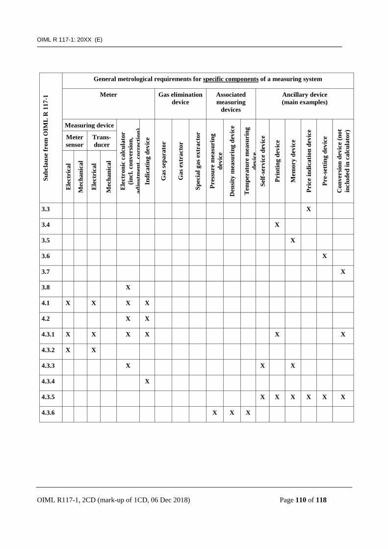
OIML R 117-1: 20XX (E)
OIML R117-1, 2CD (mark-up of 1CD, 06 Dec 2018) Page 110 of 118
Subc
laus
e fr
om O
IML
R 1
17-1
General metrological requirements for specific components of a measuring system
Meter Gas elimination device
Associated measuring
devices
Ancillary device (main examples)
Measuring device E
lect
roni
c ca
lcul
ator
(in
cl. c
onve
rsio
n,
adju
stm
ent,
corr
ectio
n)
Indi
catin
g de
vice
Gas
sepa
rato
r
Gas
ext
ract
or
Spec
ial g
as e
xtra
ctor
Pres
sure
mea
suri
ng
devi
ce
Den
sity
mea
suri
ng d
evic
e
Tem
pera
ture
mea
suri
ng
devi
ce
Self-
serv
ice
devi
ce
Prin
ting
devi
ce
Mem
ory
devi
ce
Pric
e in
dica
tion
devi
ce
Pre-
sett
ing
devi
ce
Con
vers
ion
devi
ce (n
ot
incl
uded
in c
alcu
lato
r)
Meter sensor
Trans-ducer
Ele
ctri
cal
Mec
hani
cal
Ele
ctri
cal
Mec
hani
cal
3.3 X
3.4 X
3.5 X
3.6 X
3.7 X
3.8 X
4.1 X X X X
4.2 X X
4.3.1 X X X X X X
4.3.2 X X
4.3.3 X X X
4.3.4 X
4.3.5 X X X X X X
4.3.6 X X X
OIML R 117-1: 20XX (E)
OIML R117-1, 2CD (mark-up of 1CD, 06 Dec 2018) Page 111 of 118
B.2.3.1 The manufacturer or approval applicant must state the rated conditions for the device they are submitting in the type approval application. See also 6.1.2.2.
B.2.9.2 National regulations can make a conversion device mandatory for some applications. In that case, the converted indications shall be indicated in normal use and the indications at metering conditions only on demand. B.2.10.2 New technologies for gas elimination devices should not limited by these requirements. B.2.16.3 Any connection that may be provided for bypassing the meter shall be closed by means of blanking flanges. However, if the operating requirements make such a bypass necessary, it shall be closed either by means of a closing disc or a double closing device with a monitoring valve in between. It shall be possible to ensure closure by means of seals, or there shall be an automatic monitoring of the double block-and-bleed valve in the bypass giving an alarm signal in case of leakage in this valve. The control valve of the double closing device mentioned before for pipework bypassing the meter, if provided, may be closed for safety reasons. In this case, any leakage shall be monitored by a pressure gauge located between the two shut off valves or by any other equivalent system. B.3.1.3 If the meter consists of both a mechanical adjustment and a display, precautions shall be taken to avoid different a indication for the same measurement. B.3.7.4 The relevant quantities to be considered are those corresponding to the characteristics of the liquid in the meter (pressure, temperature, etc.). B.4.2.1 and B.4.2.2 The requirements of 4.2.1 and 4.2.2 may be met by use of an external emergency power supply. When this is the case, the type approval certificate shall clearly specify this installation requirement. In this case the type approval certificate of the calculator with indicating device shall specify very clearly that this requirement applies to the measuring system in which the calculator and indicating device is intended to be included. The type approval certificate of the measuring system may specify tests to check this requirement during initial verification of the measuring system. B.4.3.2.1 By applying security level B, as defined in ISO 6551 Cabled transmission of electric and/or electronic pulsed data this provision is presumed to be fulfilled.

OIML R 117-1: 20XX (E)
OIML R117-1, 2CD (mark-up of 1CD, 06 Dec 2018) Page 112 of 118
B.4.3.3.1 Possible solutions to bullet 1:
• summing up all instruction and data codes and comparing the sum with a fixed value; • line and column parity bits (LRC and VRC); • cyclic redundancy check (CRC 16); • double independent storage of data.
Possible solutions to bullet 2:
• write-read routine; • conversion and reconversion of codes; • use of "safe coding" (check sum, parity bit); • double storage.
B.4.3.3.2 This check may be carried out by such means as parity bit, check sum, or double storage. B.4.3.4 During verification, determining that the checking facility of the indicating device is working can be achieved (for example), either:
• by disconnecting all or part of the indicating device; or • by an action which simulates a failure in the display, such as using a test button.
B.4.3.4.3 Possible solutions for this section:
• for indicating devices using incandescent filaments or LEDs, measuring the current in the filaments;
• for indicating devices using fluorescent tubes, measuring the grid voltage; • for indicating devices using electromagnetic shutters, checking the impact of each shutter; • for indicating devices using multiplexed liquid crystals, output checking of the control voltage
of segment lines and of common electrodes, so as to detect any disconnection or short circuit between control circuits.
B.5.1.3 This section describes the interpretation of the relevant articles of R 117, related to the omitting of the gas elimination device in fuel dispensers, other than LPG dispensers, intended for installation in a system with a submerged pump. When the measuring system is intended for installation in a centrally pumped system, or for a remote pump, the general provisions in 2.10 shall be applied, e.g. the provisions in 2.10.1. Because of the pumped flow, the provisions of 2.10.2 are also applicable. As a general rule, a gas elimination device is to be installed. However, the second paragraph of point 5.1.3 says:

OIML R 117-1: 20XX (E)
OIML R117-1, 2CD (mark-up of 1CD, 06 Dec 2018) Page 113 of 118
“If it is not intended to install a gas elimination device, the manufacturer or installer has to prove that there is no risk of air intake or gas release. In this case, the minimum level in the storage tank must be automatically secured and any leakage shall be checked”.
When no gas elimination device is installed, these prescriptions may be fulfilled by applying all of the following provisions 1 to 8. 1. Air intake / Minimum level To secure automatically the minimum level in the storage tank, a level detection system shall be installed. This system prevents the submerged pump from being used when the liquid level reaches a minimum level above the inlet of the pump, so that there is no risk of air intake. The minimum level that has to be respected is given by the following formula: h ≥ k.v² / 2.g where: h: minimum level of the liquid above the suction inlet of the pump [m] v: maximum velocity of the liquid at the pump inlet [m/s] g: acceleration of gravity [m/s²] k: security factor (k is at least equal to 6) with k = 6 the formula becomes:
h ≥ 3v² / g 2. Gas release Gas can be generated during shut down periods as a result of a temperature drop. If it can not be proven by calculation (see 2.13.2) that the gaseous formation has a specific effect smaller than or equal to 1 % of the minimum measured quantity (see 10.2.2) than at least one of the following provisions shall be applied to ensure that no released gas will be in the system at the start of and during the delivery: 2.1 A detection system based on a pressure control device holds the pressure of the liquid always
well above the vapor pressure. 2.2 Each delivery shall be delayed until the submerged pump has been running for at least
3 seconds. 3. Leak detection A leak detection system shall be installed.
OIML R 117-1: 20XX (E)
OIML R117-1, 2CD (mark-up of 1CD, 06 Dec 2018) Page 114 of 118
Detection of any leakage in the line shall result in stopping or preventing of any delivery. The detection system of 2.1 can fulfil the leak detection function.
4. Pipeline construction
The pipelines between the pump unit and the dispenser are installed with a positive slope of at least 1 %. There shall be no significant portion without slope. No high points are allowed upstream of each dispenser, except for those needed for the connection with other dispensers.
5. Non-return valve At least one non-return valve shall be installed in the system. It is advisable to install a non-return valve upstream of every measurement transducer. Note: this non-return valve shall not be likely to create gaseous formations. 6. Security of the devices All the devices mentioned shall be in “positive” security so that no delivery is possible if one of these devices fails. It shall be possible to check if the electronic devices (e.g. by simulation) are functioning correctly. 7. Type approval The type approval certificate of the fuel dispenser shall clearly describe the above provisions 1 to 7 that have to be followed to allow the omitting of the gas elimination device. 8. Initial verification The initial verification of the fuel dispenser shall include examination on the site of use with respect to the above provisions:
• testing the positive security of all the devices; • checking the correct functioning of the electronic devices by simulation; • checking that the prescription for the minimum level is fulfilled; • checking the presence of a leak detection system; • if applicable, checking the delay time of delivery for each dispenser; and • checking the slope of the pipes on drawings.

OIML R 117-1: 20XX (E)
OIML R117-1, 2CD (mark-up of 1CD, 06 Dec 2018) Page 115 of 118
B.5.4.2 Possible solutions: A pressure maintaining device, located downstream of the meter, ensures that the product in the meter remains in a liquid state during the measurement. The necessary pressure could be maintained either at a fixed value or at a value adjusted to suit the measurement conditions. When the pressure is maintained at a fixed value, this value shall be at least equal to the vapor pressure of the product at a temperature 15 °C above the highest possible operating temperature. It shall be possible to protect the adjustment of the pressure maintaining device with a seal. When the pressure is adjusted to suit the measurement conditions, this pressure shall exceed the vapor pressure of the liquid during the measurement by at least 100 kPa (1 bar). This adjustment shall be automatic.
Convener note: this section moved into section 3.9 on SSD A.6.1.10 For example, it is not necessary to perform the expansion test of a hose in a fuel dispenser when the hose in this measuring system is identical to the hose equipping another measuring system already approved with the same minimum measured quantity. B.6.2.1 Examples It is necessary to make a distinction between a pattern of a meter intended to measure several products (in the same measuring system) and a pattern of a meter of which different copies may be used for measuring different products (in different measuring systems), each copy being intended to measure a given product only. For example, meter A may be intended to measure diesel and gasoline alternatively, whereas meter B is intended to measure either diesel or gasoline. Both meters will be subject to accuracy tests with diesel and with gasoline at the time of type approval. For meter A, the error curves for gasoline and for diesel shall both be within the maximum permissible errors as specified in 3.1.2. For meter B, the error curves for diesel on the one hand, and for gasoline on the other hand, shall satisfy the maximum permissible errors; unlike meter A, however, these error curves may be determined using different copies of the meter, or alternatively on the same copy whose adjustment (or correction parameters) has been modified between the test with diesel and the test with gasoline. Copies of meter A will bear the mention of diesel and gasoline on their data plate and they may also be used to measure mixtures of diesel and gasoline in any proportion. Copies of meter B will bear either the mention "diesel" or "gasoline" and shall be used for measuring the corresponding product exclusively.

OIML R 117-1: 20XX (E)
OIML R117-1, 2CD (mark-up of 1CD, 06 Dec 2018) Page 116 of 118
The preliminary verification of pattern A copies may be carried out with either diesel or gasoline, indifferently (with, if appropriate, a reduction of the maximum permissible errors range). In general, the preliminary verification of pattern B copies will be carried out with the liquid intended to be measured; however, it may be carried out with the other liquid provided that the maximum permissible errors have been shifted. The value of shifting shall be determined at the time of pattern evaluation by evaluating the deviation between the error curves determined with diesel and with gasoline, on the same meter, without modification of the adjustment. These deviations shall be reproducible, from one copy of the meter to another. To check this, it is necessary to carry out accuracy tests on several instruments. B.6.2.2.1 (bullet 4) states:
• for measuring systems on road tankers, the gas elimination device shall be tested for the removal of air pockets by emptying the supply tank (compartment) during a delivery (product depletion test).
On multiple-compartment road tankers, only one compartment needs to be emptied to satisfy this requirement.

OIML R 117-1: 20XX (E)
OIML R117-1, 2CD (mark-up of 1CD, 06 Dec 2018) Page 117 of 118
Annex C
Bibliography
[Convener’s note: The contents of this Bibliography will be fully checked and updated before publication.]
[1] International vocabulary of metrology - Basic and general concepts and associated terms
(VIM), 2007 [2] International vocabulary of terms in legal metrology (VIML). OIML, Paris, 2000 [3] The International System of Units (SI), 8th edition, BIPM, Paris, 2006 [4] International Document OIML D 2: Legal units of measurement, OIML, Paris, 1999 +
Amendment 2004 [5] International Document OIML D 11: General requirements for electronic measuring
instruments. OIML, Paris, 2004 [6] Guide to the expression of uncertainty in measurement (GUM). BIPM, IEC, IFCC, ISO,
IUPAC, IUPAP and OIML. ISO, Geneva, 1995 [7] OIML International Recommendation R 118. Testing procedures and test report format
for pattern evaluation of fuel dispensers for motor vehicles. OIML, Paris, 1995 [8] ISO 7637-1: 2002 Road vehicles - Electrical disturbances from conduction and coupling
-- Part 1: Definitions and general considerations, ISO, Geneva, 2002 with amendment 1 (2002)
[9] ISO 7637-2: 2004 Road vehicles - Electrical disturbances from conduction and coupling -- Part 2: Electrical transient conduction along supply lines only, ISO, Geneva, 2004 with amendment 1 (2004)
[10] ISO 16750: 2006 Road vehicles - Environmental conditions and testing for electrical and electronic equipment - Part 2: Electrical loads, ISO, Geneva, 2006
[11] IEC 60068-2-1 (2007-03) Environmental testing, Part2: Tests, Test A: Cold. [12] IEC 60068-2-2 (1974-01), with amendments 1 (1993-02) and 2 (1994-05) Environmental
testing Part2: Tests. Test B: Dry heat. [13] IEC 60068-2-30 (2005-08) Environmental testing Part 2: Tests. Test Db and guidance:
Damp heat, cyclic (12 + 12-hour cycle). [14] IEC 60068-2-47 (2005-04) Environmental testing Part 2-47: Test methods, Mounting of
components, equipment and other articles for vibration, impact and similar dynamic tests. [15] IEC 60068-2-64 (1993-05), with Corrigendum 1(1993-10) Environmental testing – Part 2:
Test methods, Test Fh: Vibration, broad-band random (digital control) and guidance. [16] IEC 60068-3-1 (1974-01) with Supplement 1 (1978-01) Environmental testing, Part 3:
Background information, section 1: Cold and dry heat tests. [17] IEC 60068-3-4 (2001-08) Environmental testing - Part 3-4:Supporting documentation and
guidance - Damp heat tests. [18] IEC/TR 61000-2-1 (1990-05) Electromagnetic compatibility (EMC) - Part 2:
Environment - Section 1: Description of the environment - Electromagnetic environment for low-frequency conducted disturbances and signaling in public power supply systems.

OIML R 117-1: 20XX (E)
OIML R117-1, 2CD (mark-up of 1CD, 06 Dec 2018) Page 118 of 118
[19] IEC 60654-2 (1979-01) with amendment 1 (1992-09) Operating conditions for industrial-process measurement and control equipment. Part 2: Power
[20] IEC 61000-4-1(2006-10) Electromagnetic compatibility (EMC), Part 4-1: Testing and measurement techniques - Overview of IEC 61000-4 series.
[21] IEC 61000-4-2 (2001-04) Electromagnetic compatibility (EMC), Part 4-2: Testing and measurement techniques - Electrostatic discharge immunity test.
[22] IEC 61000-4-3 (2006-02) Electromagnetic compatibility (EMC): Part 4-3: Testing and measurement techniques - Radiated, radio-frequency, electromagnetic field immunity test.
[23] IEC 61000-4-4 (2004-07) with correction 1 (2006-08) Electromagnetic compatibility (EMC) - Part 4: Testing and measurement techniques - Section 4: Electrical fast transient/burst immunity test. Basic EMC Publication.
[24] IEC 61000-4-5 (2005-11) Electromagnetic compatibility (EMC) - Part 4-5: Testing and measurement techniques - Surge immunity test.
[25] IEC 61000-4-6 (2003-05) with amendment 1 (2004-10) and amendment 2 (2006-03) Electromagnetic compatibility (EMC): Part 4: Testing and measurement techniques, Section 6: Immunity to conducted disturbances, induced by radio-frequency fields. Consolidated Edition: IEC 61000-4-6 (2006-05) Ed. 2.2.
[26] IEC 61000-4-11 (2004-03) - Part 4-11: Testing and measuring techniques - Voltage dips, short interruptions and voltage variations immunity tests.
[27] IEC 61000-4-17 (2002-07) Consolidated edition 1.1 Electromagnetic compatibility (EMC) - Part 4-17: Testing and measurement techniques - Ripple on d.c. input power port immunity test.
[28] IEC 61000-4-29 (2000-08) Electromagnetic compatibility (EMC) - Part 4-29: Testing and measurement techniques - Voltage dips, short interruptions and voltage variations on d.c. input power port immunity tests.
[29] IEC 61000-6-1 (2005-03) Electromagnetic compatibility (EMC) - Part 6-1: Generic standards - Section 1: Immunity for residential, commercial and light-industrial environments.
[30] IEC 61000-6-2 (2005-01) Electromagnetic compatibility (EMC) - Part 6-2: Generic standards - Immunity for industrial environments.