ordering conductivity, ph/orp & disinfection...
TRANSCRIPT

Conductivity, pH/ORP & Disinfection
Summary of Key Benefits
180625.C Nov 2014
Ordering Information
NEW!! W600 Series Controllers
Large touchscreen display with icon based programming makes setup easy
Universal sensor input provides extraordinary flexibility; the same controller can be used with almost any type of sensor needed
Optional dual analog (4-20 mA) input for Fluorometers or nearly any other process value
Multiple language support allows simple setup no matter where your business takes you
Six control outputs allow the controller to be used in more applications
Economical wall-mount package for easy installation
On-screen graphing of sensor values and control output status
Complete flexibility in the function of each relay • On/Off Setpoint• Time Proportional Control• Pulse Proportional Control (when purchased with solid-state relays)• In-Range or Out-of-Range activation• Probe wash• Timer-based activation• Activation based upon the state of a contact closure• Timed activation triggered by a Water Contactor or Paddlewheel flow meter’s accumulated total flow• Activate with another output• Activate as a percent of another output’s on-time• Alarm• For Cooling Tower and Boiler applications:
• Biocide Timer• Boiler blowdown on conductivity using intermittent sampling
Datalogging
Ethernet option for remote access via the Internet or LAN
The W600 series provides reliable, flexible and powerful control for your water treatment program.
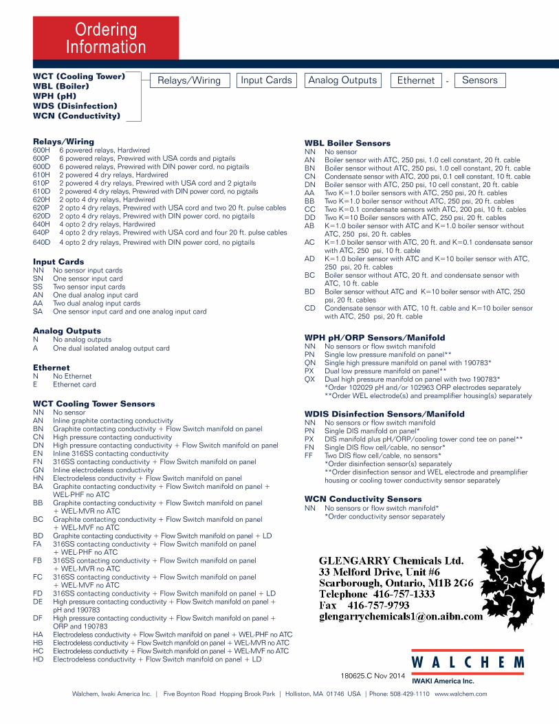
WCT (Cooling Tower)WBL (Boiler)WPH (pH)WDS (Disinfection)WCN (Conductivity)
Relays/Wiring Sensors-Input Cards Analog Outputs Ethernet
Walchem, Iwaki America Inc. | Five Boynton Road Hopping Brook Park | Holliston, MA 01746 USA | Phone: 508-429-1110 www.walchem.com
Relays/Wiring 600H 6 powered relays, Hardwired600P 6 powered relays, Prewired with USA cords and pigtails 600D 6 powered relays, Prewired with DIN power cord, no pigtails 610H 2 powered 4 dry relays, Hardwired610P 2 powered 4 dry relays, Prewired with USA cord and 2 pigtails 610D 2 powered 4 dry relays, Prewired with DIN power cord, no pigtails 620H 2 opto 4 dry relays, Hardwired 620P 2 opto 4 dry relays, Prewired with USA cord and two 20 ft. pulse cables620D 2 opto 4 dry relays, Prewired with DIN power cord, no pigtails640H 4 opto 2 dry relays, Hardwired 640P 4 opto 2 dry relays, Prewired with USA cord and four 20 ft. pulse cables 640D 4 opto 2 dry relays, Prewired with DIN power cord, no pigtails
Input Cards NN No sensor input cardsSN One sensor input cardSS Two sensor input cardsAN One dual analog input cardAA Two dual analog input cards SA One sensor input card and one analog input card
Analog Outputs N No analog outputsA One dual isolated analog output card
Ethernet N No EthernetE Ethernet card
WCT Cooling Tower Sensors NN No sensorAN Inline graphite contacting conductivityBN Graphite contacting conductivity + Flow Switch manifold on panelCN High pressure contacting conductivityDN High pressure contacting conductivity + Flow Switch manifold on panelEN Inline 316SS contacting conductivityFN 316SS contacting conductivity + Flow Switch manifold on panelGN Inline electrodeless conductivityHN Electrodeless conductivity + Flow Switch manifold on panelBA Graphite contacting conductivity + Flow Switch manifold on panel + WEL-PHF no ATCBB Graphite contacting conductivity + Flow Switch manifold on panel + WEL-MVR no ATCBC Graphite contacting conductivity + Flow Switch manifold on panel + WEL-MVF no ATCBD Graphite contacting conductivity + Flow Switch manifold on panel + LDFA 316SS contacting conductivity + Flow Switch manifold on panel + WEL-PHF no ATCFB 316SS contacting conductivity + Flow Switch manifold on panel + WEL-MVR no ATCFC 316SS contacting conductivity + Flow Switch manifold on panel + WEL-MVF no ATCFD 316SS contacting conductivity + Flow Switch manifold on panel + LDDE High pressure contacting conductivity + Flow Switch manifold on panel + pH and 190783DF High pressure contacting conductivity + Flow Switch manifold on panel + ORP and 190783HA Electrodeless conductivity + Flow Switch manifold on panel + WEL-PHF no ATCHB Electrodeless conductivity + Flow Switch manifold on panel + WEL-MVR no ATCHC Electrodeless conductivity + Flow Switch manifold on panel + WEL-MVF no ATCHD Electrodeless conductivity + Flow Switch manifold on panel + LD
WBL Boiler SensorsNN No sensorAN Boiler sensor with ATC, 250 psi, 1.0 cell constant, 20 ft. cable BN Boiler sensor without ATC, 250 psi, 1.0 cell constant, 20 ft. cable CN Condensate sensor with ATC, 200 psi, 0.1 cell constant, 10 ft. cable DN Boiler sensor with ATC, 250 psi, 10 cell constant, 20 ft. cable AA Two K=1.0 boiler sensors with ATC, 250 psi, 20 ft. cables BB Two K=1.0 boiler sensor without ATC, 250 psi, 20 ft. cables CC Two K=0.1 condensate sensors with ATC, 200 psi, 10 ft. cables DD Two K=10 Boiler sensors with ATC, 250 psi, 20 ft. cables AB K=1.0 boiler sensor with ATC and K=1.0 boiler sensor without ATC, 250 psi, 20 ft. cablesAC K=1.0 boiler sensor with ATC, 20 ft. and K=0.1 condensate sensor with ATC, 250 psi, 10 ft. cable AD K=1.0 boiler sensor with ATC and K=10 boiler sensor with ATC, 250 psi, 20 ft. cablesBC Boiler sensor without ATC, 20 ft. and condensate sensor with ATC, 10 ft. cable BD Boiler sensor without ATC and K=10 boiler sensor with ATC, 250 psi, 20 ft. cables CD Condensate sensor with ATC, 10 ft. cable and K=10 boiler sensor with ATC, 250 psi, 20 ft. cable
WPH pH/ORP Sensors/ManifoldNN No sensors or flow switch manifoldPN Single low pressure manifold on panel** QN Single high pressure manifold on panel with 190783* PX Dual low pressure manifold on panel** QX Dual high pressure manifold on panel with two 190783* *Order 102029 pH and/or 102963 ORP electrodes separately **Order WEL electrode(s) and preamplifier housing(s) separately
WDIS Disinfection Sensors/ManifoldNN No sensors or flow switch manifoldPN Single DIS manifold on panel* PX DIS manifold plus pH/ORP/cooling tower cond tee on panel** FN Single DIS flow cell/cable, no sensor* FF Two DIS flow cell/cable, no sensors* *Order disinfection sensor(s) separately **Order disinfection sensor and WEL electrode and preamplifier housing or cooling tower conductivity sensor separately
WCN Conductivity SensorsNN No sensors or flow switch manifold* *Order conductivity sensor separately

Specifications Specifications
InputsPower 100-240 VAC, 50 or 60 Hz, 7A max Fuse: 6.3 Amp
OutputsPowered Mechanical Relays (0 or 6 model code dependent) Pre-powered on circuit board switching line voltageAll relays are fused together as one group, total current must not exceed 6A (resistive), 1/8 HP (93W)
Dry Contact Mechanical Relays (0, 2 or 4 model code dependent)6 A (resistive), 1/8 HP (93W)Dry contact relays are not fuse protected.
Pulse Outputs (0, 2 or 4 model code dependent)Opto-isolated, solid-state relay, 200mA, 40V DC VLOWMAX = 0.05V @ 18mA
4 - 20 mA (0 or 2 model code dependent) Internally powered, Fully isolated600 Ohm max resistive load, Resolution 0.0015% of spanAccuracy ± 0.5% of reading
Mechanical (Controller)Enclosure Material Polycarbonate Enclosure Rating NEMA 4X (IP65)Dimensions 9.5 x 8 x 4” (241 x 203 x 102 mm)Display 320 x 240 pixel monochrome backlit display with touchscreen Ambient Temperature -4 to 131°F (-20 to 55°C)Storage Temperature -4 to 176°F (-20 to 80°C)
Measurement PerformanceRange Resolution Accuracy
0.01 Cell Contacting Conductivity 0-300 µS/cm 0.01 µS/cm, 0.0001 mS/cm, 0.001 mS/m, 0.0001 S/m, 0.01 ppm ± 1% of reading
0.1 Cell Contacting Conductivity 0-3,000 µS/cm 0.1 µS/cm, 0.0001 mS/cm, 0.01 mS/m, 0.0001 S/m, 0.1 ppm ± 1% of reading
1.0 Cell Contacting Conductivity 0-30,000 µS/cm 1 µS/cm, 0.001 mS/cm, 0.1 mS/m, 0.0001 S/m, 1 ppm ± 1% of reading
10.0 Cell Contacting Conductivity 0-300,000 µS/cm 10 µS/cm, 0.01 mS/cm, 1 mS/m, 0.001 S/m, 10 ppm ± 1% of reading
pH -2 to 16 pH units 0.01 pH units ± 0.01% of reading
ORP -1500 to 1500 mV 0.1 mV ± 1 mV
Disinfection sensors -2000 to 1500 mV 0.1 mV ± 1 mV
0 - 2 ppm to 0 - 20,000 ppm Varies with range and slope Varies with range and slope
Electrodeless Conductivity 500 - 12,000 µS/cm 1 µS/cm, 0.01 mS/cm, 0.1 mS/m, 0.001 S/m, 1 ppm ± 1% of reading
3,000-40,000 µS/cm 1 µS/cm, 0.01 mS/cm, 0.1 mS/m, 0.001 S/m, 1 ppm ± 1% of reading
10,000-150,000 µS/cm 10 µS/cm, 0.1 mS/cm, 1 mS/m, 0.01 S/m, 10 ppm ± 1% of reading
50,000-500,000 µS/cm 10 µS/cm, 0.1 mS/cm, 1 mS/m, 0.01 S/m, 10 ppm ± 1% of reading
200,000-2,000,000 µS/cm 100 µS/cm, 0.1 mS/cm, 1 mS/m, 0.1 S/m, 100 ppm ± 1% of reading
Temperature 23 to 500°F (-5 to 260°C) 0.1°F (0.1°C) ± 1% of reading within range
Mechanical (Sensors)
Sensor Pressure Temperature Materials Process Connections
Electrodeless conductivity 0-140 psi (0 to 9.6 bar) CPVC: 32-158°F (0 to 70°C) PEEK: 32-190°F (0 to 88°C)
CPVC, FKM in-line o-ring PEEK, 316 SS in-line adapter
1” NPTM submersion 2” NPTM in-line adapter
pH 0-100 psi (0 to 6.9 bar) 50-158°F (10-70°C) CPVC, Glass, FKM o-rings, HDPE, Titanium rod, glass-filled PP tee
1” NPTM submersion 3/4” NPTF in-line teeORP 0-100 psi (0 to 6.9 bar) 32-158°F (0-70°C)
Contacting conductivity 0-200 psi (0 to 13.8 bar) 32-248°F (0-120°C) 316SS, PEEK 3/4” NPTM
Free Chlorine/Bromine 0-14.7 psi (0 to 1.0 bar) 32-113°F (0-45°C)
PVC, Polycarbonate, silicone rubber, SS, PEEK, FKM, Isoplast
1/4” NPTF Inlet3/4” NPTF Outlet
Extended pH Range Free Chlorine/Bromine
0-14.7 psi (0 to 1.0 bar) 32-113°F (0-45°C)
Total Chlorine 0-14.7 psi (0 to 1.0 bar) 32-113°F (0-45°C)
Chlorine Dioxide 0-14.7 psi (0 to 1.0 bar) 32-131°F (0-55°C)
Ozone 0-14.7 psi (0 to 1.0 bar) 32-131°F (0-55°C)
Peracetic Acid 0-14.7 psi (0 to 1.0 bar) 32-131°F (0-55°C)
Hydrogen Peroxide 0-14.7 psi (0 to 1.0 bar) 32-113°F (0-45°C)
Flow switch manifold 0-150 psi (0 to 10.3 bar) up to 100°F (38°C) 0-50 psi (0 to 3.4 bar) at 140°F (60°C)
32-140°F (0-60°C) GFRPP, PVC, FKM, Isoplast
3/4” NPTF
Dimensions
Agency CertificationsSafety: UL 61010-1:2012, 3rd Edition
CSA C22.2 No.61010-1:2012, 3rd EditionIEC 61010-1:2010 3rd EditionEN 61010-1:2010 3rd Edition
EMC: IEC 61326-1:2005EN 61326-1:2006
Note: For EN61000-4-6, EN61000-4-3 the controller met perfor-mance criteria B. This equipment is suitable for use in establish-ments other than domestic and those directly connected to a low voltage (100-240 VAC) power supply network which supplies buildings used for domestic purposes.
0 10 15 20 25 30 35 40 50 60 70 80 90 100 110 120 130 140 150 160 170 180
181.3 139.9 124.2 111.1 100.0 90.6 82.5 75.5 64.3 55.6 48.9 43.5 39.2 35.7 32.8 30.4 28.5 26.9 25.5 24.4 23.6 22.9
Temperature °C
Range Multiplier %Note: Conductivity ranges above apply at 25°C. At higher temperatures, the range is reduced per the range multiplier chart.
Sensor Input Signals (0, 1 or 2 depending on model code)Contacting Conductivity: 0.01, 0.1, 1.0, or 10.0 cell constant, or Electrodeless Conductivity or Disinfection or Amplified pH or ORP which requires a preamplified signal. Walchem WEL or WDS series recommended. ±5VDC power available for external preamps.
Each sensor input card contains a temperature input.Temperature: 100 or 1000 ohm RTD, 10K or 100K Thermistor
Analog (4-20 mA) Sensor Input (0, 2 or 4 depending on model code)2-wire loop powered and self-powered transmitters supported3-wire and 4-wire transmitters supportedEach sensor input board has two channels: Channel 1, 130 ohm input resistance and Channel 2, 280 ohm input resistanceAvailable Power: Two independent isolated 24 VDC ± 15% supplies per board. 1.5 W maximum for each channel. 2W (83 mA at 24 VDC) total power consumption for all channels (four total channels if two boards are installed; 2W is equivalent to 2 Little Dipper sensors)
Digital Input Signals (6): State-Type Digital Inputs Electrical: Optically isolated and providing an electrically isolated 9V power with a nominal 2.3mA current when the digital input switch is closed. Typical response time: < 2 seconds. Devices supported: Any isolated dry contact (i.e. relay, reed switch). Types: Interlock
Low Speed Counter-Type Digital InputsElectrical: Optically isolated and providing an electrically isolated 9V power with a nominal 2.3mA current when the digital input switch is closed, 0-10 Hz, 50 msec minimum width. Devices supported: Any device with isolated open drain, open collector, transistor or reed switch. Types: Contacting Flowmeter
High Speed Counter-Type Digital InputsElectrical: Optically isolated and providing an electrically isolated 9V power with a nominal 2.3mA current when the digital input switch is closed, 0-250 Hz, 1.25 msec minimum width. Devices supported: Any device with isolated open drain, open collector, transistor or reed switch. Types: Paddlewheel Flowmeter
9.0in(228.60mm)
2.0in(50.80mm)
4.0in(101.60mm)
10.0in(254.53mm)
8.0in(203.10mm)
4.9in(123.60mm)
9.8in(248.92mm)
4.0in(102.49mm)
Conductivity, pH/ORP & Disinfection
Summary of Key Benefits
180625.C Nov 2014
Ordering Information
NEW!! W600 Series Controllers
Large touchscreen display with icon based programming makes setup easy
Universal sensor input provides extraordinary flexibility; the same controller can be used with almost any type of sensor needed
Optional dual analog (4-20 mA) input for Fluorometers or nearly any other process value
Multiple language support allows simple setup no matter where your business takes you
Six control outputs allow the controller to be used in more applications
Economical wall-mount package for easy installation
On-screen graphing of sensor values and control output status
Complete flexibility in the function of each relay • On/Off Setpoint• Time Proportional Control• Pulse Proportional Control (when purchased with solid-state relays)• In-Range or Out-of-Range activation• Probe wash• Timer-based activation• Activation based upon the state of a contact closure• Timed activation triggered by a Water Contactor or Paddlewheel flow meter’s accumulated total flow• Activate with another output• Activate as a percent of another output’s on-time• Alarm• For Cooling Tower and Boiler applications:
• Biocide Timer• Boiler blowdown on conductivity using intermittent sampling
Datalogging
Ethernet option for remote access via the Internet or LAN
The W600 series provides reliable, flexible and powerful control for your water treatment program.
WCT (Cooling Tower)WBL (Boiler)WPH (pH)WDS (Disinfection)WCN (Conductivity)
Relays/Wiring Sensors-Input Cards Analog Outputs Ethernet
Walchem, Iwaki America Inc. | Five Boynton Road Hopping Brook Park | Holliston, MA 01746 USA | Phone: 508-429-1110 www.walchem.com
Relays/Wiring 600H 6 powered relays, Hardwired600P 6 powered relays, Prewired with USA cords and pigtails 600D 6 powered relays, Prewired with DIN power cord, no pigtails 610H 2 powered 4 dry relays, Hardwired610P 2 powered 4 dry relays, Prewired with USA cord and 2 pigtails 610D 2 powered 4 dry relays, Prewired with DIN power cord, no pigtails 620H 2 opto 4 dry relays, Hardwired 620P 2 opto 4 dry relays, Prewired with USA cord and two 20 ft. pulse cables620D 2 opto 4 dry relays, Prewired with DIN power cord, no pigtails640H 4 opto 2 dry relays, Hardwired 640P 4 opto 2 dry relays, Prewired with USA cord and four 20 ft. pulse cables 640D 4 opto 2 dry relays, Prewired with DIN power cord, no pigtails
Input Cards NN No sensor input cardsSN One sensor input cardSS Two sensor input cardsAN One dual analog input cardAA Two dual analog input cards SA One sensor input card and one analog input card
Analog Outputs N No analog outputsA One dual isolated analog output card
Ethernet N No EthernetE Ethernet card
WCT Cooling Tower Sensors NN No sensorAN Inline graphite contacting conductivityBN Graphite contacting conductivity + Flow Switch manifold on panelCN High pressure contacting conductivityDN High pressure contacting conductivity + Flow Switch manifold on panelEN Inline 316SS contacting conductivityFN 316SS contacting conductivity + Flow Switch manifold on panelGN Inline electrodeless conductivityHN Electrodeless conductivity + Flow Switch manifold on panelBA Graphite contacting conductivity + Flow Switch manifold on panel + WEL-PHF no ATCBB Graphite contacting conductivity + Flow Switch manifold on panel + WEL-MVR no ATCBC Graphite contacting conductivity + Flow Switch manifold on panel + WEL-MVF no ATCBD Graphite contacting conductivity + Flow Switch manifold on panel + LDFA 316SS contacting conductivity + Flow Switch manifold on panel + WEL-PHF no ATCFB 316SS contacting conductivity + Flow Switch manifold on panel + WEL-MVR no ATCFC 316SS contacting conductivity + Flow Switch manifold on panel + WEL-MVF no ATCFD 316SS contacting conductivity + Flow Switch manifold on panel + LDDE High pressure contacting conductivity + Flow Switch manifold on panel + pH and 190783DF High pressure contacting conductivity + Flow Switch manifold on panel + ORP and 190783HA Electrodeless conductivity + Flow Switch manifold on panel + WEL-PHF no ATCHB Electrodeless conductivity + Flow Switch manifold on panel + WEL-MVR no ATCHC Electrodeless conductivity + Flow Switch manifold on panel + WEL-MVF no ATCHD Electrodeless conductivity + Flow Switch manifold on panel + LD
WBL Boiler SensorsNN No sensorAN Boiler sensor with ATC, 250 psi, 1.0 cell constant, 20 ft. cable BN Boiler sensor without ATC, 250 psi, 1.0 cell constant, 20 ft. cable CN Condensate sensor with ATC, 200 psi, 0.1 cell constant, 10 ft. cable DN Boiler sensor with ATC, 250 psi, 10 cell constant, 20 ft. cable AA Two K=1.0 boiler sensors with ATC, 250 psi, 20 ft. cables BB Two K=1.0 boiler sensor without ATC, 250 psi, 20 ft. cables CC Two K=0.1 condensate sensors with ATC, 200 psi, 10 ft. cables DD Two K=10 Boiler sensors with ATC, 250 psi, 20 ft. cables AB K=1.0 boiler sensor with ATC and K=1.0 boiler sensor without ATC, 250 psi, 20 ft. cablesAC K=1.0 boiler sensor with ATC, 20 ft. and K=0.1 condensate sensor with ATC, 250 psi, 10 ft. cable AD K=1.0 boiler sensor with ATC and K=10 boiler sensor with ATC, 250 psi, 20 ft. cablesBC Boiler sensor without ATC, 20 ft. and condensate sensor with ATC, 10 ft. cable BD Boiler sensor without ATC and K=10 boiler sensor with ATC, 250 psi, 20 ft. cables CD Condensate sensor with ATC, 10 ft. cable and K=10 boiler sensor with ATC, 250 psi, 20 ft. cable
WPH pH/ORP Sensors/ManifoldNN No sensors or flow switch manifoldPN Single low pressure manifold on panel** QN Single high pressure manifold on panel with 190783* PX Dual low pressure manifold on panel** QX Dual high pressure manifold on panel with two 190783* *Order 102029 pH and/or 102963 ORP electrodes separately **Order WEL electrode(s) and preamplifier housing(s) separately
WDIS Disinfection Sensors/ManifoldNN No sensors or flow switch manifoldPN Single DIS manifold on panel* PX DIS manifold plus pH/ORP/cooling tower cond tee on panel** FN Single DIS flow cell/cable, no sensor* FF Two DIS flow cell/cable, no sensors* *Order disinfection sensor(s) separately **Order disinfection sensor and WEL electrode and preamplifier housing or cooling tower conductivity sensor separately
WCN Conductivity SensorsNN No sensors or flow switch manifold* *Order conductivity sensor separately