optoplextm mems tunable filter products - optoplex ... mems tunable filters...optoplex c o r p o r a...
TRANSCRIPT

OptoplexC O R P O R A T I O N
TMOptoplexC O R P O R A T I O N
TM
C O R P O R A T I O N
TM MEMS Tunable Filter Products
MEMS Technology Optoplex’s MEMS Tunable Optical Filter is based on a patented micro-optic design with MEMS tuning technology. It is an integrated module consisting of a MEMS chip, micro-optics and control electronics and interface. When receiving a stream of optical signals of a plurality of wavelengths from the Input-Port (IN), the 2-port tunable optical filter directs a selected channel to the Output-Port (OUT). Wavelength (frequency) tuning is achieved by changing driving voltage applied to the MEMS chip, via the control electronics and the built-in firmware.
The MEMS tunable filter offers high optical filtering performance: low insertion loss and high adjacent and non-adjacent channel isolation. Moreover, the MEMS tunable filter provides high-speed tuning that is highly demanded in many applications. The standard optical tunable filter product family includes 50- and 100-GHz channel spacing.
Optoplex’s MEMS tunable filter is ideal for applications from wavelength locking, optical channel monitoring and optical add/drop in optical communications; optical filtering and wavelength management in fiber sensing and spectroscopic instrumentation.
Applications Wavelength selection in DWDM systems Optical performance monitoring Optical spectrum analyzer Tunable optical noise filtering Noise suppression for optical amplifiers
Key Features and Benefits
Athermal design Fast tuning speed Compact size Wide tuning range, covering entire C-band or L-band Low TDL and WDL Low & uniform insertion loss High channel isolation Low power consumption Telcordia GR-1221 qualified
Gaussian Spectral Shape
The tunable filter is based on optical grating and MEMS technology and the spectral shape is Gaussian-type. See Figure 2a and Figure 2b.
IN OUTIN OUT
Figure 1, Functional block diagram of a tunable filter
Figure 2a, Gaussian Spectral Shape (center wavelength at 1527nm)
Figure 2b, Gaussian Spectral Shape (center wavelength at 1567nm)

Compact Design
The MEMS tunable filter is designed and assembled in a compact module. For instance, the optical engine of a 50GHz tunable filter is about 56x27x9.99m, while a 100GHz one (optical engine) is 35x25x8.5mm. The full function tunable filter module (including control electronics) is about 100x60x12mm.
Easy to Use The MEMS tunable is controlled with driving voltage. With the optical engine, a analog driving voltage is from -60 to +60VDC. In the tunable filter full function module, a voltage converter is built-in, and the driving voltage is from -5VDC to +5VDC. In manufacturing, the wavelength vs driving voltage is well calibrated (including the effect of operating temperature). With the calibration data, the user can easily tune the tunable filter to desired wavelength in an optical engine with analog interface. Or in a full function module, the user just needs to simply issue a command to tune the device to required wavelength.
Figure 4a, Wavelength vs Voltage tuning curve of a 50GHz MEMS TF
Figure 3a, Photo of a 100GHz MEMS TF (optical engine with analog control interface, no control electronics included) . The size is 35 x 25 x 8.5mm.
Figure 3a, Photo of a 50GHz MEMS TF full functional module with control electronics included . The size is 104 x52.5 x 12.5mm.
Figure 4b, Wavelength vs Voltage tuning curve of a 100GHz MEMS TF

Fast Tuning Speed
The MEMS tunable filters are designed to have fast tuning speed. For a MEMS TF of 50GHz channel spacing operating in C-band, the fastest tuning speed from channel-1 to channel-88 is less than 3 ms.
With optimized design and control, the tunable filter’s tuning speed is rated as less than 20ms from any channel to any other channel in the C-band for 50GHz channel spacing MEMS TF. Engineered Spectral Profiles
As standard offers, a 100GHz (channels spacing) MEMS TF has a typical 3dB BW of 60GHz while the standard 50GHz one has a 3dB BW of 30GHz. For 50GHz, we have a narrower BW version with a 3dB BW, typically, of 20GHz. The spectral profile can be custom-engineered to meet special requirements. Contact Optoplex for details. Wavelength Coverage For 50GHz channel spacing (3dB BW of 30GHz or 20GHz), we offer C-band or L-band wavelength coverage. For 100GHz, we can cover C, L-, C+L or O-band (1260 ~ 1360nm).
A full-band version with wavelength coverage from 1250 ~ 1650nm is available with FWHM of 4nm. Contact Optoplex for details.
Figure 6, Tuning speed (time) from CH-1 to CH-88 and then to CH-1.
Figure 5a, Tuning from CH-1 to CH-88
Figure 5b, Tuning from CH-88 to CH-1
Figure 7, a 100GHz MEMS Tunable Filter with C+L Band Coverage
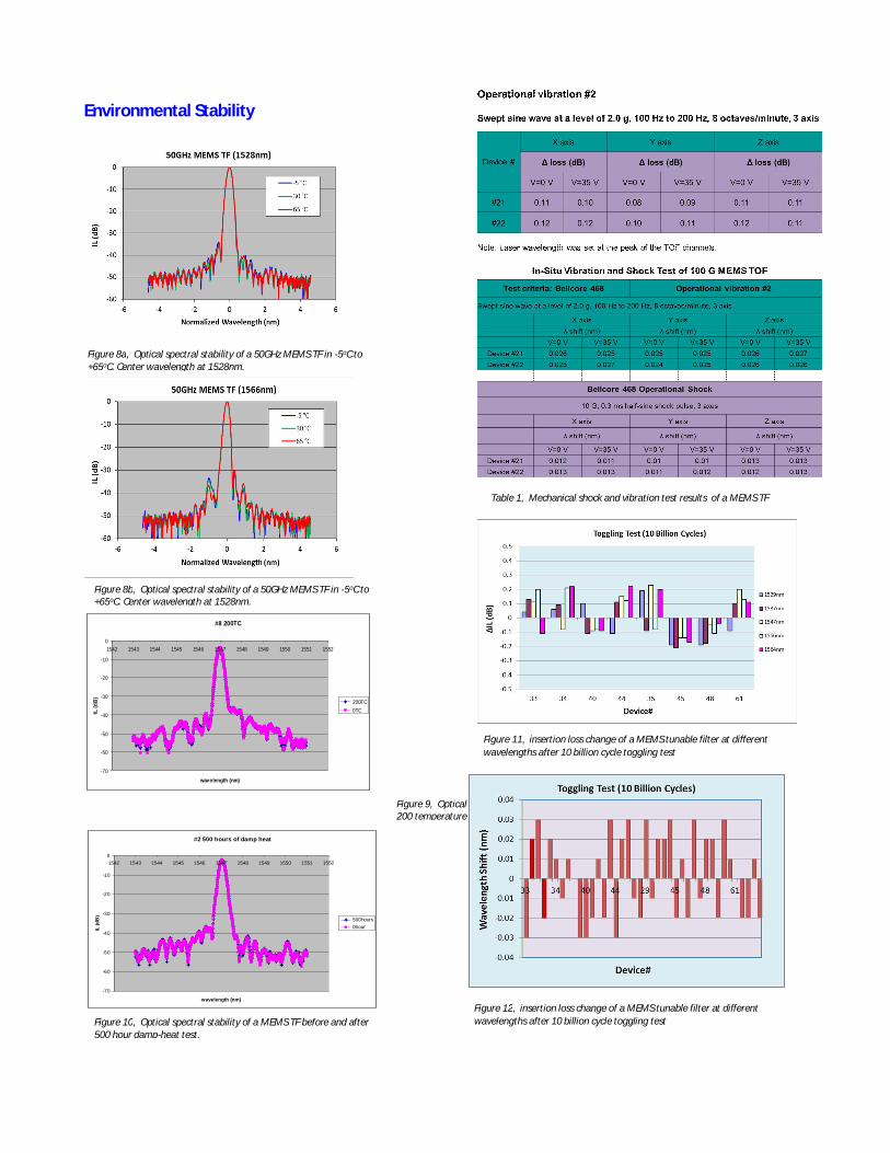
Environmental Stability
#2 500 hours of damp heat
-70
-60
-50
-40
-30
-20
-10
01542 1543 1544 1545 1546 1547 1548 1549 1550 1551 1552
wavelength (nm)
IL (d
B)
500hours0hour
Figure 8a, Optical spectral stability of a 50GHz MEMS TF in -5oC to +65oC. Center wavelength at 1528nm.
Figure 8b, Optical spectral stability of a 50GHz MEMS TF in -5oC to +65oC. Center wavelength at 1528nm.
#8 200TC
-70
-60
-50
-40
-30
-20
-10
01542 1543 1544 1545 1546 1547 1548 1549 1550 1551 1552
wavelength (nm)
IL (d
B) 200TC0TC
Figure 9, Optical spectral stability of a MEMS TF before and after 200 temperature cycling test.
Figure 10, Optical spectral stability of a MEMS TF before and after 500 hour damp-heat test.
Figure 11, insertion loss change of a MEMS tunable filter at different wavelengths after 10 billion cycle toggling test
Table 1, Mechanical shock and vibration test results of a MEMS TF
Figure 12, insertion loss change of a MEMS tunable filter at different wavelengths after 10 billion cycle toggling test

Parameter1) Unit 50 GHz Std. 50 GHz NB2) 100 GHz
Wavelength Tuning Range nm C - band: 1528 ~ 1562; L - band: 1567 ~ 1603
Wavelength Tuning Resolution pm ~ 10 pm or Calibrated to ITU grids
Passband Width @ 1.0 dB GHz > 16 - > 25
Passband Width @ 3.0 dB GHz 30 (typical) 16.5 to 23.0 60
Passband Width @ 20 dB GHz <85 < 75 < 185
Peak Insertion Loss (without connector) dB < 5.0 < 6.0 < 4.0
Polarization Dependent Loss dB < 0.5 < 0.5 < 0.3
Chromatic Dispersion ps/nm ± 5 ± 5 ± 5
Wavelength Setting Error GHz < ±4 < ±4 < ±5
Wavelength Repeatability GHz 1 1 1
Return Loss dB > 40
Maximum Input Optical Power mW 500
Tuning Speed (channel to channel)
ms < 20
Tuning Voltage V < 65 < 85 < 38
Operating Temperature °C -5 to 75
Storage Temperature °C - 40 to 85
Dimension (L W H)
(Optical Engine) mm 57×26×9.9 85×45×15 35×25×8.5
Dimension (L X W X H) (Full Functional Module)
104 x 52.5 x 12.5 104 x 52.5 x 12.5
Table 2. Performance Specifications of MEMS Tunable Filters
Notes: 1) Unless Otherwise indicated, all performances are specified in the operating conditions: optical power, wavelength
and temperature ranges 2) NB: Narrow-Band 50GHz MEMS Tunable Filter

Optical Engines Optoplex can supply either the optical engines of the MEMS tunable filters with analog control interface. Calibration tables (refer to Figures 4a and 4b) of wavelength vs driving voltage at different temperatures will be provided by Optoplex. With this info, the user can build their own control electronics and algorithm to control the MEMS tunable filters.
Full Function Modules Full functional MEMS tunable filter module in which driving and control electronics are built-in together with firmware are commercially available. With the full-function MEMS tunable filter, the user just needs to follow the electrical communication interface definition and control the MEMS tunable filter with FW command from a host. Optoplex also supplies an evaluation kit (including a software program and a USB cable). With the evaluation kit, the user can run the program in a computer to control the MEMS TF directly.
50GHz NB (18GHz FWHM)
68x32x9mm
35x25x8.5mm
100GHz
35x25x8.5mm
100GHz
50GHz
100GHz Module
104x52.5x12.9mm
50GHz Module
104x52.5x12.9mm
50GHz
56x25x9mm
56x25x9.9mm
50GHz
MEMS Tunable Filter Products
Figure 13, Optical engine of a 100GHz MEMS tunable filter
Figure 14, Optical engine of a std 500GHz MEMS tunable filter
Figure 15, Optical engine of a std 500GHz MEMS tunable filter
Figure 16, Optical engine of a narrow bandwidth 500GHz MEMS tunable filter
Figure 17, 100GHz MEMS tunable filter module
Figure 18, 50GHz (std.) MEMS tunable filter module
Figure 18, 50GHz (narrow bandwidth version) MEMS tunable filter module

Ordering Information Below is the general information for ordering for Optoplex’s standard MEMS tunable filters. Table 3, Ordering info of standard MEMS tunable filters
Channel Spacing
Operating Wavelength Range
Optical TF Engine, P/N
Full Function TF Module, P/N
100GHz C-Band TO-2C2NM300 TO -2C2FM500
L-Band TO -2L2NM310 TO -2L2FM510
C+L Band TO -2T2NM320 TO -2T2FM520
O-Band TO -2O2NM330 TO -2O2FM530
50GHz C-Band TO -1C2NM400 TO -1C2FM600
L-Band TO -1L2NM410 TO -1L2FM610
C+L Band TO -1T2NM420 TO -1T2FM620
O-Band TO -1O2NM430 TO -1O2FM630
Custom design and manufacturing are available upon request. Contact Optoplex for details.
Contact Information
Optoplex Corporation 3374 Gate Boulevard Fremont, CA 94538 USA
Tel: (510) 490-9930 Fax: (510) 490-9330
www.optoplex.com [email protected]
Sales
[email protected] Technical Support