optiworx 870 mhz isx3022 power domain optical...
TRANSCRIPT
OptiworxTM 870 MHz ISX3022 PowerDomain Optical Distribution Node
Procedures Manual1082434 Rev B

Procedures Manualfor
870 MHz ISX3022Power Domain Optical Distribution Node

ISX3022 870 MHz ISX3022 Power Domain Optical Distribution NodeC-COR.net Document Number: 1082434, Revision B
Copyright © 2001 C-COR.net Corp. All rights reserved.
Trademarks
C-COR, C-COR Electronics, DV6000, FlexNet, I-Flex, LITEAMP, and SMART-NETT are registered trademarks and Cable
Network Manager, CNM, COR-Convergence, COR-Connect, FlexNode, lumaCOR, naviCOR, Transfer Linearization, and
TL Technology are trademarks of C-COR.net Corp. All other brand and product names are trademarks or registered
trademarks of their respective companies.
Contents and specifications within this manual are subject to change without notice.

Page v
Contacting C-COR.net Technical SupportContact Information
You can contact C-COR.net by phone, e-mail, Internet, fax, or mail. When contacting C-COR.net TechnicalSupport, please be prepared to provide the information listed below:
• Your name
• Your company name and address
• Your phone and fax number
• Your e-mail address
• The system site
• A description of the problem(s) you are experiencing
• Any equipment part/model numbers related to your specific problem(s)
• The best way to contact you (phone, fax, e-mail, or mail)
• The best time to contact you
Phone
Call the C-COR.net worldwide headquarters 24 hours a day, 7 days a week on the C-COR.net Technical SupportHotline:
Technical Support Hotline: 888-827-2267
Or, call C-COR.net worldwide headquarters Monday through Friday (8 AM to 5 PM ET [+5GMT]) and ask forthe Applications Engineering and Training Department:
State College Office: +1-814-231-4422Toll Free: 800-233-2267
Send an e-mail including the contact information listed in Contact Information:[email protected]
Visit us on the World Wide Web at:
http://www.c-cor.net
From the C-COR.net home page, you can:
• Submit your problem or Technical Publication request electronically;(Services > Technical Support > Technical Support Form)
or
• Download a product manual (if currently available);(Services > Technical Support > Technical Documentation)

Page vi
Fax
Send a fax with a cover sheet including the information listed in Contact Information:
814-237-5831
Send your letter including the information listed in Contact Information:Attn: Applications Engineering and Training DepartmentC-COR.net Corp.60 Decibel RoadState College, PA 16801-7580 USA
Providing Feedback on this PublicationC-COR.net welcomes your suggestions and assistance in identifying any errors, inaccuracies, or misleadinginformation. Please contact our Technical Publications Department with an E-mail referencing the documentnumber and page number(s) to which the feedback applies.
Send your e-mail to:

Page vii
AdmonishmentsImportant safety admonishments appear throughout this document to warn of possible hazards to persons or
equipment. An admonishment identifies a possible hazard and then explains what may happen if the hazard is not
avoided. The admonishments — in the form of Danger, Warning, and Caution notes — must be heeded at all times.
A triangular safety icon flags these notes, which are defined below in descending order of severity of injury or
damage and likelihood of occurrence.
Danger: Danger indicates the presence of a hazard which will cause severe personal injury, death, or
substantial property damage if the hazard is not avoided.
Warning: Warning indicates the presence of a hazard that can cause severe personal injury, death, or
substantial property damage if the hazard is not avoided.
Caution: Caution indicates the presence of a hazard that will or can cause minor personal injury or property
damage if the hazard is not avoided.

Page viii
Revision History
REVISION DATE REASON FOR CHANGE
1 11/99 Partial first draft: pages 15 and 58-61 (of 64) incomplete
2 11/99 Complete first draft, with changes from preliminary review
3 2/00 Final review draft
A 3/00 Initial release
B 11/01 Trademark Update

Page 1
OptiworxTM 870 MHz ISX3022 PowerDomain Optical Distribution Node
Installation InstructionsContent Page
2. DESCRIPTION.................................................................................................................................... 3
3. SPECIFICATIONS............................................................................................................................ 11
4. INSTALLATION............................................................................................................................... 15
A. PRE-MOUNT PREPARATION OF BASE ASSEMBLY .............................................................................. 16B. PRE-MOUNT PREPARATION OF LID ASSEMBLY ................................................................................. 21C. CLEANING AND MATING FIBER OPTIC CONNECTORS AND ADAPTERS .............................................. 27D. MOUNTING THE PREPARED ISX3022 ............................................................................................... 35E. CONNECTING COAXIAL CABLES AND FIBER OPTIC STUB CABLE ...................................................... 36F. CONFIGURING THE INSTALLED ISX3022: AC FUSES........................................................................ 43G. CONFIGURING THE INSTALLED ISX3022: EQUALIZERS .................................................................... 46H. CONFIGURING THE INSTALLED ISX3022: PADS AND TERMINATORS (FORWARD PATH) ................... 47J. CONFIGURING THE INSTALLED ISX3022: PADS AND TERMINATORS (RETURN PATH) ...................... 52K. CLOSING THE CONFIGURED ISX3022 ............................................................................................... 55
5. PARTS LIST ...................................................................................................................................... 57
1. GENERAL
1.01 This document provides procedures for installation of an Optiworx ISX3022 PowerDomain Optical Distribution Node (PDN) in the various configurations in which it may bereceived from the factory.

PN 1082434Revision B, November 2001
Page 2
(This page intentionally left blank)
PN 1082434Revision B, November 2001
Page 3
2. DESCRIPTION
2.01 The ISX3022 node (Figures 1 and 2) is a modular, bi-directional, broadband hybrid fibercoax (HFC) distribution station for cable television and added services such as telephony anddata transfer. It is the ISX-series node optimized for “power domain” network architectures.“Power domain” designs define each node service area by the amount of active plant that can bepowered from a power supply co-located with the node. This typically extends the reach ofoptical fiber into the network, reduces amplifier cascades, and enhances network capacity andoperating efficiency.
2.02 The ISX3022 occupies a two-piece, strand mount, weather-tight aluminum housing. Thehousing base provides ports for all external power and RF connections and holds an RF trayassembly of specified forward path distribution amplifier and AC-to-DC power supplycomponents. The motherboard in the RF tray also accepts plug-in mounting of an optional returnpath fiber optic transmitter module. See Figure 2. A plug-in base-to-lid cable assemblyelectrically interconnects the RF tray motherboard and a second motherboard mounted at thebottom of the lid casting
2.03 Each end of the lid casting offers a port for fiber optic cable entry. The lid includeshardware for managing fiber routing. An incoming connectorized fiber plugs directly into theinstalled optical receiver module. If a return path transmitter is installed, the connector on itscaptive output fiber mates with a connectorized outgoing fiber at a bulkhead adapter in the lid’sfiber management area.
9323-B
65
4
RF/PWR PORTS
9 IN.
9 IN.
(22.9 CM)
(22.9 CM)
18 IN.(45.7 CM)
FIBER ENTRYPORT (1 OF 2)
PORT 4
PORT 5
PORT 6
STRANDCLAMPS
Figure 1. ISX3022 Power Domain Optical Distribution Node
PN 1082434Revision B, November 2001
Page 4
2.04 A separate plug-in coaxial cable carries the receiver module’s RF output from the lidmotherboard to the motherboard in the RF tray.
2.05 ISX3022 units are offered with RF tray motherboards initially equipped for 2-, 3-, or 4-port operation. A 2- or 3-port unit can be expanded to 3- or 4-port capacity by field replacementof just the RF tray assembly. Because the base castings of all units are identical, there is no needto disturb existing RF connections when replacing an RF tray.
2.06 Figure 3 shows forward-path RF signal flow through currently offered lid motherboardconfigurations and through a fully equipped 4-port ISX3022 PDN. The lid motherboard supportsan optical receiver module, plugged into motherboard socket J4. The optical fiber carrying theincoming signal connects directly to the receiver module. Receiver RF output connects through acoaxial element in hybrid connector J4 and circuit board tracks to SMB coaxial connector J9.
2.07 At the RF tray in the ISX3022 base, the forward path signal arriving from the lid boardcan be accessed at test point J7, or a forward path test signal can be injected at point J8. Thereare 10 RF test points on the base motherboard. Each features a “F” type directionally coupled –20dB connection which provides –20dB of attenuation between the test connector and the relatedactual point in the signal path through the node. The forward path signal passes through primary
Figure 2. Major Component Locations in ISX3022
PN 1082434Revision B, November 2001
Page 5
attenuator pad A4 and equalizer A20 to amplifier U2. The output of this primary gain stagepasses through signature correcting device A5 and is then split to feed four separate distributionpaths. Each path has its own secondary attenuator pad, equalizer socket, and output gain stage.Each of these amplifiers feeds its output through the high-pass side of a diplex filter to one of thefour RF distribution ports in the base casting beneath the RF tray. Separate forward and returnpath test points connect to each of the four diplexer-to-port lines.
Figure 3. ISX3022 Forward Path RF Signal Flow

PN 1082434Revision B, November 2001
Page 6
2.08 Primary equalizer position A20 must have an equalizer installed to complete the forwardsignal path; a 0dB equalizer is used if no equalization is required. Secondary equalizers areoptional. Each of positions A22 through A25 comes with factory installed jumpers, to be cut if asecondary equalizer is added. The device installed in position A5 may look like yet anotherequalizer, but it is actually a signature correcting assembly factory customized and installed atfinal test to ensure that all ports in a node deliver similar performance.
2.09 Port 2 is for a dedicated AC power connection only. The port 5 position included in thebase casting is not used in ISX3022 applications.
2.10 The 2- and 3-port versions of the ISX3022 differ from what Figure 3 shows for the 4-port version only as follows:
Only ports 1 and 4 are enabled in the 2-port version. Amplifiers U5 and U4, diplexers A7and A8, and associated parts for ports 3 and 6 are omitted from the 2-port motherboard.
Ports 1, 4, and 6 are enabled in the 3-port version. Port 3 amplifier U5, diplexer A7, andassociated parts are omitted.
2.11 Figure 4 shows return-path signal flow. Return path signals from subscriber premisesenter the node through an enabled RF port and connect internally to the common terminal of thatport’s diplexer. A directionally coupled RF test point there provides access (with signalsattenuated –20dB) for setup, maintenance, and troubleshooting purposes. Return path signalsemerging from the low-pass side of a diplexer go through a level-adjusting attenuator pad to oneof four port input terminals in the socket A3 area centered in the motherboard. Socket A3 acceptsplug-in installation of a return path optical transmitter module.
Note: The 5-42 MHz return path passband shown in Figures 3 and 4 is the U.S.convention. Accommodating other conventions such as 5-30 MHz, 5-55 MHz, or5-65 MHz requires an RF tray with different diplex filters.
2.12 Return transmitters come in various types and power ratings, but signal flow through allmodels is as shown in Figure 4:
The return path RF inputs from all active ports are combined and fed into the first ofthree successive gain stages. A directional coupler follows this first gain stage.
Following the directional coupler is an attenuator pad socket that lets the user adjust thelevel of the composite RF signal reaching the second gain stage. (Transmitter modulesalso contain two additional pad sockets—not accessible to the user and not shown inFigure 4—for individual factory adjustment of each module’s performance.)
A directionally coupled test point (type F connector) at the output of the final gain stageenables RF monitoring of laser drive. The signal level delivered here is factory adjustedto be at –20dB relative to the level at the active ports, assuming 0dB pads in theindividual port path and transmitter module pad sockets.
Laser output goes through a captive optical fiber to the fiber management area in the lid.There the connectorized fiber from the transmitter module mates at a bulkhead adapterwith the connectorized outgoing fiber provided at node installation.

PN 1082434Revision B, November 2001
Page 7
Laser output goes through a captive optical fiber to the fiber management area in the lid.There the connectorized fiber from the transmitter module mates at a bulkhead adapterwith the connectorized outgoing fiber provided at node installation.
Figure 4. ISX3022 Return Path RF Signal Flow

PN 1082434Revision B, November 2001
Page 8
2.13 Figure 5 shows the routing of AC power through the ISX3022 node. The four RF ports(1, 3, 4, and 6) are all power-isolated, allowing any of them also to be used for AC power inputor feedthrough. Port 2 is a dedicated power entry port, without RF connections. The port 5position is not used in ISX3022 nodes.
2.14 The fuseholder interconnections shown support two basic AC powering and powerdistribution scenarios:
Where AC comes in at one end and may be passed on to the other, a nonfusing shunt isused in F9. Fuses are installed for the port that is to receive the AC input, for any otherport(s) meant to pass AC on, and for F7, which separately fuses the input to the AC-to-DC power supply on the bottom of the RF tray. Other fuseholder positions are leftempty. A power clamping surge protector in holder clips A1 protects the power supplyagainst power line voltage surges.
Leaving the F9 fuseholder empty splits the two ends of the node and lets two ACsupplies feed into it to meet greater downstream power demand. At the left-hand (ports1-3) end, fuses are installed for the port that is to receive one of the AC inputs, for anyother port(s) meant to pass AC on, and for F7, to fuse the input to the node’s AC-to-DCpower supply. At the right-hand end of the RF tray, a fuse is installed for both ports 4and 6. This interconnects the incoming second AC input and the downstream loads to befed through the other port. Note that in this configuration the ISX3022 itself does notdraw any operating power from the AC source connected to port 4 or 6.
2.15 For troubleshooting, the ISX3022 base tray motherboard contains green “pilot light”LED’s for the +24 and +12 VDC supply lines. Both LED’s DS1 (next to +24 V test point TP2)and DS2 (next to + 12 V test point TP1) should always be lighted whenever the node is powered.
2.16 All return transmitter modules for plug-in use on the RF tray motherboard also include a
Figure 5. ISX3022 AC Power Distribution

PN 1082434Revision B, November 2001
Page 9
“pilot light” indicator. This is a two-color LED. Its green element should be lighted whenever thenode is powered, to indicate that the transmitter module is receiving +12 VDC from the node’sAC-to-DC power supply. The LED turns red if laser bias current rises to a factory programmedlimit value. Such an event does not shut down the transmitter. The red signal means that the laseris approaching the end of its service life, output power may decrease, and the transmitter moduleshould be replaced. Transmitter modules also include tip-jack test points at which a techniciancan measure a voltage representation of the transmitter’s optical output power.
2.17 Each of the receivers for plug-in installation in the lid are assembled in a self-containedaluminum enclosure. The bottom face of each module contains a hybrid connector (in-line pinsfor power and logic connections combined with a coaxial element for RF) to mate with theappropriate motherboard connector. Two captive screws in each module mechanically secure itto the lid casting. The top surface of each optical receiver is stepped to provide a recessed spacefor its optical connection to an incoming fiber. The topmost faces of all modules also includeLED status indicators and any connectors needed for local technician access.
2.18 Optical receiver modules (for lid motherboard socket J4 — Figure 3) operate over afrequency range of 40-870 MHz. Each receives its forward-path optical signal through abulkhead connector in the riser of its stepped top section. It converts this optical input to an RFoutput that it delivers through the coaxial element in its bottom hybrid connector. The topmostface of each receiver includes:
Test point tip-jacks labeled COM and IPD at which a technician can measure a voltage(V/mW) derived from photodiode current to determine the received optical power level.
A red LED labeled ALARM. This LED is for future use.

PN 1082434Revision B, November 2001
Page 10
(This page intentionally left blank)

PN 1082434Revision B, November 2001
Page 11
3. SPECIFICATIONS
Note: The specifications listed here are current as of the date of publication of thismanual. C-COR.net reserves the right to change specifications without prior notice. Youmay verify the product specifications by contacting Sales or Technical Support.
3.01 Table 1 details the specifications for the ISX3022 node. Individual componentspecifications and overall performance characteristics are listed in separate subdivisions of thetable.
3.02 Table 2 contains information about power consumption for various configurations of theISX3022 node, over the usable range of AC input voltages.
Table 1. ISX3022 Specifications
PARAMETER SPECIFICATION REMARKS
Forward Path Optical ReceiverWavelengthPassbandOptical input power level
Optical input return lossRF output power level
Frequency responseSlope
Model IX22FPRXAx1260 to 1610nm40 - 870 MHz0dBm (1mW) typical; –7dBm
min. to +3dBm max.> 55dB25.5dBmV
±0.5dB0 to +2dB, +1.0dB typical
Dependent on channel loadand expected CNR
With 0dBm optical receivedpower & 2.25% OMI/channel
Forward Path RF AmplifierPassband
Frequency responseSlopeRF output return loss (75 Ω)Group delayHum modulation
Number of output portsOutput level (each port)Minimum full gain (all 4 ports
enabled)Operating gain (all 4 ports
enabled)Level controlSlope control
54 – 870 MHz
±0.75dB< 2.0dB, 1.5dB typical> 16dB< 20ns–70dBc
4 standard; 2 or 3 optional+44dBmV typical27dB (28 dB typical) from input
to tray at J25 to port output26dB
0 - 20dB plug-in pads750 MHz: 0 - 16dB plug-in
equalizers870 MHz: 0 - 14dB plug-in
equalizers
With 42/54 MHz diplexers;other options available
With 0 dB equalizers
Over any 3.58 MHz bandwidthAt 12 A RMS AC power, full
op. temp., 54 – 870 MHz
Individually adjustable 0–20 BWith 0dB equalization and
0dB padsWith primary slope module,
0dB pads0.5dB increments1dB increments
1dB increments
(Table continues on next page)
PN 1082434Revision B, November 2001
Page 12
Table 1. ISX3022 Specifications (Continued)
PARAMETER SPECIFICATION REMARKS
RF Tray Forward PathPerformance
Channel loading: VSB/AMDigital tier loading:①
80 NTSC320 MHz
112 NTSC120 MHz
60 PALNone
Reference frequencyReference slope (linear)Reference output level (all
ports)CNR②
CTB③
CSO③
XMOD③
54/550/870 MHz12dB+32/39/44dBmV
65dB–76dBc–82dBc–76dBc
54/750/870 MHz12dB+32/42/44dBmV
65dB–67dBc–70dBc–67dBc
54/750/870 MHz12dB+32/42/44dBmV
65dB–76dBc–82dBc–76dBc
① Simulated digital loading using white noise at 10dB below analog carriers as measured at the inputto the transmitter
② –0.25dB for every 1dB drop in RF output below + 44dBmV, +0.25dB for every 1dB rise in RFoutput above + 47dBmV
③ Assumes no distortion contribution from transmitter or fiber — actual system performance is less
Return RF PathPassband
Channel loadInput level (at station port)Frequency responseRF input return loss (75 Ω)Group delay
Level control
5 – 40 MHz
4 carriers+17dBmV±0.75dB> 16dB< 30ns
0 - 20dB plug-in pads
With 42/54 MHz diplexers;other options available
Over any 1.5 MHz band-width
0.5dB steps
Return Path OpticalTransmitterLaser typeWavelengthPassband
Frequency responseChannel loadRF input level
OMI per carrierOptical power outputOptical return lossSpurious noise
Return Path PerformanceData EquivalentChannel loadInput levelLink budget
BER
Model IX22RPTXB
Fabry-Perot1285 - 1335nm5 – 55 MHz
±1.0dB4 carriers+17dBmV
18%1mW (0dBm)>55dB–40dBc
23+9.5dBmV/each8dB
10-6
Model IX22RPTXH
Direct feedback DFB1285 - 1335nm5 – 55 MHz
±1.0dB4 carriers+17dBmV
17%1mW (0dBm)>55dB–40dBc
23+9.5dBmV/each8dB
10-6
(Other RTX modules arealso available)
Passband is further limitedby port diplex filters used
Each of 4 carriers, at ports,with 0dB port pads and1dB RTX pad
Relative to a carrier at 20%OMI
1.5 MHz QPSKAt ports, with 0dB padsAll fiber loss into
HX6213RX23 1.5 MHz QPSK carriers
(Table continues on next page)
PN 1082434Revision B, November 2001
Page 13
Table 1. ISX3022 Specifications (Continued)
PARAMETER SPECIFICATION REMARKS
Return Path Performance(Continued)
Video EquivalentChannel load
Input levelLink budget
CNRCSOCTB
RTX ModelIX22RPTXB
4
+17dBmV/each8dB
45dB–45dBc–60dBc
RTX ModelIX22RPTXH
4
+17dBmV/each8dB
47dB–50dBc–60dBc
T-channels (13, 19, 25, 31MHz
At ports, with 0dB padsAll fiber loss into
HX6213RX
Test PointsTip jacks for test probes:
On base tray motherboardTP1: +12 V supply voltageTP2: +24 V supply voltageTP3: AC supply voltageTP4: CommonTP5: AC supply voltage
In optical receiver modulesCOM: CommonIPD: Photodiode current
In optical transmitter moduleGND: CommonLASER POWER
Type F coaxial connectors,as directionally coupled RFtest points:
On base tray motherboard10: forward & return foreach of four ports; forward &signal injection for main pathfrom lid
In optical transmitter module1 return for the compositesignal modulating the laser
Expected nominal values:
+12 VDC ±10%+24 VDC ±10%35 - 95 VACGround reference point35 - 95 VAC
Ground reference point1 VDC = 1mW optical rec’d power
Ground reference point1 VDC = 1mW optical output power
–20dB ±0.75dB relative to thesignal point tapped
–20dB ±0.75dB relative to RFinput to ports, with 0dB port padsand 0dB RTX pad installed
From/to port(s) 1 - 3
From/to port(s) 4 - 6
See Figure 3, page 5
See Figure 4, page 7
Recommended Torque Valuesfor Threaded Connections
Housing closure boltsRF tray holddown boltsStinger interconnectorsPort connectors, terminators, &
caps
7 to 9 ft-lb18 in.-lb18 in.-lb30 in.-lb
(Table continues on next page)

PN 1082434Revision B, November 2001
Page 14
Table 1. ISX3022 Specifications (Continued)
PARAMETER SPECIFICATION REMARKS
MechanicalDimensions (H x W x D)Weight
9 x 18 x 9 inches30 lb maximum Fully loaded
EnvironmentalOperating temperature –40º to +60º C (–40º to +140º F)
Connection InterfacesRF distribution cables and local
power connector (if used)Fiber optic connector(s) on re-
ceiver module and bracket infiber management area
Standard KS 5/8-24 75 Ohm entryport connector (stinger)
FC/UPC, FC/APC, SC/UPC, orSC/APC
Pin length: 7/8 - 15/16 inch
Single mode fiber
Operating PowerPower input required
Internal power supply output
AC bypass current
35 - 95 V, 50 - 60 Hz
23.75 – 24.25 VDC, 4 A maximum11.75 – 12.25 VDC, current 1 A max.15 A maximum
Square wave AC, in throughport 1, 2, 3, 4, or 6
Through any single port
Table 2. Typical Power Consumption For ISX3022 Nodes
NODE CONFIGURATION
2 PORTSENABLED
3 PORTSENABLED
4 PORTSENABLED
RCVRONLY
RCVR& RTX
RCVRONLY
RCVR& RTX
RCVRONLY
RCVR& RTX
INTERNAL DC LOAD (WATTS)
39 42 49.5 52.5 60 63
ACVOLTSIN
AC CURRENT DRAW (AMPS) FOR NODE ITSELF
35 1.4 1.6 1.9 2.0 2.3 2.5
45 1.1 1.2 1.3 1.4 1.6 1.7
55 1.0 1.1 1.2 1.2 1.3 1.4
65 1.0 1.0 1.1 1.1 1.2 1.3
75 1.0 1.0 1.0 1.1 1.2 1.2
85 0.9 0.9 1.0 1.0 1.1 1.1
95 0.9 0.9 1.0 1.0 1.1 1.1

PN 1082434Revision B, November 2001
Page 15
4. INSTALLATION
4.01 Installation consists of:
Unpacking the ISX3022, opening it, and verifying its factory configuration for theintended application.
Preparing base and lid assemblies for strand mounting.
Mounting the ISX3022 on the strand and making up coaxial and fiber optic connections.
Configuring the ISX3022 for required AC power routing, tilt-correcting RF equalization,and RF operating levels.
4.02 Listed below are the tools needed to install and configure this unit:
Open end wrenches to fit 1/2-inch and 3/4-inch hex heads and sizes of hex nuts on portentry connectors used (or two adjustable wrenches with suitable jaw-opening range)
Ratchet handle for sockets and 6- or 12-point sockets in 1/2- and 3/4-inch sizes
Torque wrenches suitable for applying 7 to 9 foot-pounds and 18 to 30 in.-lb of torque
Hex nut drivers in 1/4- and 1/2-inch sizes
Flat-bladed and Phillips-head screwdrivers
Coaxial cable tools: cable cutter, jacket stripper or penknife, coring tool, centerconductor cleaning tool
Heat gun and power source to operate it
Digital voltmeter
Optical power meter
Optical fiber scope (such as Noyes Fiber Systems OFS-300, with adapter for type ofoptical connector used)
Small end-cutting wire cutter
The following materials are also required:
Pin-type (“stinger”) coaxial cable connectors, 5/8-24 equipment entry, 75 Ohm, sized forcenter conductor and outside diameters of cable(s) to be connected (Gilbert EngineeringGRS-xxx-CH-xx or equivalent); one for each RF or power port to be used
KS port terminator, 5/8-24 equipment entry, 75 Ohm, AC power blocked (Gilbert GTR-M or equivalent); one for any enabled RF port not currently to be used
5/8-24 plug with sealing gasket; one for any case opening not associated with an enabledport and not already factory sealed (item A5 or A7, page 57)
Fiber optic stub cable with 5/8-24 entry connector, fibers connectorized at one end tomatch lid module bulkhead adapter(s), cable long enough to reach fiber splice enclosureand let ODN optical lid be lowered to the ground if necessary (item M1, page 60)
Heat-shrink tubing of appropriate size(s) to seal around connectors and cables used
Fiber connector/adapter cleaning kit (item M2, page 60), or lint-free wipes, isopropylalcohol, lint-free cotton swabs, lint-free pipe cleaners, and oil-free compressed air
PN 1082434Revision B, November 2001
Page 16
Silicone grease (GE G-623 or equivalent)
ATO fuse(s) as required (item C4 or C7, page 60)
Plug-in equalizer(s) as required (item C3, page 59)
Plug-in pads or terminators as required (item C1, page 59)
A. Pre-mount Preparation of Base Assembly
1. Unpack the ISX3022 shipping carton. Verify the contents and inspect for damage.
Caution: Avoid opening the ISX3022 enclosure in wet weather. Moisture may damageelectronic components within the case. Because the case provides a weather tight sealwhen closed, any moisture that gets inside will remain there when the case is reclosed.
2. Loosen the six captive bolts that hold the lid assembly to the base assembly and open theISX3022 enclosure.
Caution: Electronic equipment can be damaged by static electrical discharge. Whenhandling the ISX3022 RF tray, always follow Electrostatic Discharge (ESD) protectionpractices. Wear a grounded wrist strap when you touch the tray or any of itscomponents. Use anti-static packaging when transporting or storing a tray removedfrom the ISX3022 base. When working on a removed tray, place it on an approved,electrically grounded anti-static mat.
3. Viewing RF tray components through the cutouts in the tray’s metal cover, check thenode’s factory-installed RF-port configuration:
If there is no hybrid amplifier IC installed in the circuit board cavity marked U5 (seeFigure 6), port 3 was not factory enabled.
If no hybrid amplifier IC is installed in the circuit board cavity marked U4 (Figure 6),port 6 was not factory enabled.
4. Check system plans for the details of intended connections to the ISX3022. Using thatinformation and the results of step 3, consult the first two columns of Table 2. For eachport, find intended port status and how the housing opening for that port must beequipped.
5. For any opening to be plugged that was not factory plugged, or that has only a temporaryunthreaded plastic plug, obtain a 5/8-24 threaded plug with sealing gasket (item A7, page57). Lightly coat the gasket with silicone grease and install the gasketed plug in the portopening (30 in.-lb torque).
6. The captive plug factory installed in one of the two casting openings for port 1, 3, 4, or 6may be blocking the opening you prefer to use for connecting to or terminating that port.If so, remove the plug, recoat its gasket with silicone grease, and install the plug in theport’s other opening (30 in.-lb torque).

PN 1082434Revision B, November 2001
Page 17
7. Undo base-to-lid wiring and fiber interconnections to prepare for removing the RF trayfrom the base casting:
Unplug the black-booted coaxial cable from J9 on the lid motherboard. (This is thecable that goes to J25 on the RF tray’s motherboard.)
Locate the clamp/ejector fingers projecting from the ends of J1 on the lid mother-board. Press these fingers outward, away from the center of J1, to disconnect and ejectthe ribbon cable plug from J1.
If a return path transmitter is installed on the RF tray motherboard, release thetransmitter’s output fiber from its attachments in the lid casting. Carefully detach thefiber and its sheathing from any clips that support them on the fiber managementassembly. Disconnect the fiber connector from the assembly’s bulkhead adapter andimmediately cap or plug the connector to keep the fiber clean.
8. Using a 1/4-inch hex nut driver (preferred) or flat-blade screwdriver, loosen the eightcaptive screws (Figure 6) that hold the RF tray in the base casting. These screws arespring loaded to pop up when disengaged.
9. Use flat-blade screwdrivers at the two pry points shown in Figure 6 to start lifting thetray from the base casting. (The initial resistance felt is from the engagement of coaxialconnectors on the bottom of the tray with interconnectors in the base casting.) When thetray comes free, remove it from the base casting. Taking care to protect the attachedcables and fiber, set the tray safely aside, cover side down.
10. Optional step: At this point, you may find it convenient to completely separate theISX3022 base and lid assemblies before proceeding to step 11. To do so:
Rotate the plastic locking barrel covering the hinge spring between base and lidcastings (Figure 7) as necessary to expose its latching joint. Use a small flat-bladescrewdriver to snap the locking barrel open, and remove the barrel from between thehinge arms of the base and lid castings.
Figure 6. ISX3022 Base Assembly
PN 1082434Revision B, November 2001
Page 18
Compressing the hinge spring (Figure 7), shift the lid assembly far enough to the leftto free the lid’s hinge pins from the base casting’s hinge arms. Separate the lid andbase assemblies, taking care not to lose the hinge spring when it is released.
11. Use a 1/2-inch nut driver to remove the port seizure/stinger interconnector (Figure 8)from each port position that is to receive either a cable connector or a port terminator.
12. Check the exposed pin length of each connector and terminator to be installed. Trim anypin that is not the length shown in Figure 9 to the specified dimension.
Table 3. ISX3022 RF Configuration Requirements
REQUIRED TO BE INSTALLED IN:
PORT STATUSHOUSING PORT
OPENINGFORWARD PAD
SOCKETRETURN PAD
SOCKET
With No Return Transmitter Installed
Forward path enabled and to be used Cable connector1 Pad2 Terminator2
Forward path enabled but currentlynot to be used
Plug3 or cable con-nector1 for future use
Terminator2 Leave empty
Forward path not enabled Plug3 Leave empty Leave empty
For Port 2 only:To be used for AC power inputNot to be used
Cable connector1
Plug3N/AN/A
N/AN/A
For Port 5 only: not used in ISX3022 Plug3 N/A N/A
With Return Transmitter Installed
Forward path enabled and to be used;return path also to be used
Cable connector1 Pad2 Pad2
Forward path enabled and to be used;return path not to be used
Cable connector1 Pad2 Terminator2
Forward path enabled but currentlynot to be used; return path onlyto be used
Cable connector1 Terminator2 Pad2
Forward path enabled but currentlynot to be used; return path alsonot to be used
Plug3 or cable con-nector1 for future use
Terminator2 Terminator2
Forward path not enabled Plug3 Leave empty Terminator2, 5
For Port 2 only:To be used for AC power inputNot to be used
Cable connector1
Plug3N/AN/A
N/AN/A
For Port 5 only: not used in ISX3022 Plug3 N/A N/A
1 Pin-type (“stinger”) coaxial cable connector, 5/8-24 equipment entry, 75 Ohm, sized for center conductor and outside diameters ofcable to be connected (Gilbert Engineering GRS-xxx-CH-xx or equivalent)
2 See item C1, page 593 5/8-24 plug with sealing gasket. item A5 or A7, page 574 KS port terminator, 5/8-24 equipment entry, 75 Ohm, AC power blocked (Gilbert Engineering GTR-M or equivalent)5 Terminator required in all trays dated before 99258. In trays after 99258, port paths not enabled are factory terminated on the
motherboard; no IPAD terminator is required.

PN 1082434Revision B, November 2001
Page 19
Figure 7. RF Tray Removal and Lid/Base Separation Details
Figure 8. Stinger Interconnectors and Port Positions
FRONTSECTION
7/8 TO 15/16
INCH
CONNECTOR(CENTER NUT)
BACKNUT
5099-E
Figure 9. Stinger Connector

PN 1082434Revision B, November 2001
Page 20
13. At the 5/8-24 threaded end of each connector or terminator to be installed, coat thefacing grommet with silicone grease.
Caution: Do not overtighten a terminator or a connector front section. Exceeding thespecified torque may impair component ability to seal moisture out of the node housing.
14. Thread each connector or terminator into the appropriate port and tighten to a torque of30 in.-lb. (If necessary with connectors, remove the center and back nuts so that torque isapplied only to the front-section nut — see Figure 9.)
15. Visually check that the stinger portion of each installed connector or terminator is lyingin one of the insulator cross channels and resting on the metal center piece at the bottomof the port seizure cavity, as shown in Figure 10.
Caution: Do not cross-thread or overtighten a stinger interconnector or its threads maybe damaged.
16. Thread each stinger interconnector removed in step 11 into its port seizure opening in thebase casting and manually turn it clockwise until the threads are properly engaged. Thentighten to a torque of 18 in.-lb.
17. Reinstall the RF tray in the base casting. Press down on the ends of the tray to seat thecoaxial connectors in the stinger interconnectors. Manually engage each of the eightcaptive screws first, and then tighten them in the sequence shown in Figure 11 to atorque of 18 in.-lb.
STINGERINTERCONNECTOR
STINGER OF CONNECTOROR TERMINATOR MUST
BE CENTERED ONMETAL PAD (VIEW
WITH STINGERINTERCONNECTOR
REMOVED)
5009-B
Figure 10. Stinger Interconnector Installation

PN 1082434Revision B, November 2001
Page 21
B. Pre-mount Preparation of Lid Assembly
1. Determine which of the two openings in the lid casting is to be used for fiber optic cableentry. If that opening is closed by a factory-installed plug, remove the plug, recoat itsgasket with silicone grease, and install the plug in the other lid-casting opening; torquethe plug to 30 in.-lb.
Caution: Fiber optic cable is sensitive to excessive pulling, bending, and crushing.Consult the cable manufacturer’s recommendations before installing the fiber optic stubcable. Do not apply more pulling force to the cable than specified. Do not bend the cablemore sharply than recommended or allow it to kink or be crushed. Do not bend theconnectorized leads (pigtails) more sharply than the minimum recommended bend radiusof 1.5 inches (3.81 cm). Improper handling may damage the optical fibers within thecable and alter the cable’s transmission characteristics.
2. Obtain and carefully unpack the fiber optic stub cable assembly to be used for thisinstallation (item M1, page 60). Using extra caution, remove protective packaging fromthe connectorized end of the cable (but do not remove dust caps from the ends of fiberoptic connectors).
Note: The stub cable may include non-connectorized fibers in addition to theconnectorized fibers. Non-connectorized fibers are spares for possible future use.
3. Verify that the connector type provided matches the bulkhead adapter(s) on the opticalreceiver and in the fiber management area of the ISX3022 lid, and that the cableassembly includes a two-piece OptiFit (or equivalent) enclosure connector and a lengthof heat shrink tubing like those shown in Figure 12.
Figure 11. Torque Pattern for RF Tray Holddown Screws

PN 1082434Revision B, November 2001
Page 22
Figure 12. Connectorized End of Fiber Optic Stub Cable
4. Slide the heat shrink tubing over the connectorized end of the fiber optic cable and moveit past the enclosure connector as shown in Figure 13.
5039-A
HEAT SHRINKTUBING
Figure 13. Prepositioning Heat Shrink Tubing
5. At the 5/8-24 threaded end of the connector, lightly coat the facing grommet withsilicone grease.
Caution: Do not exceed the recommended 1.5-inch (3.81 cm) bend radius when passingfiber leads through the fiber port. Do not pull or apply tension to the fiber leads orconnectors, or damage may occur.
6. With the dust caps still attached, pass the connectorized fiber leads (one at time) throughthe fiber entry port as shown in Figure 14.

PN 1082434Revision B, November 2001
Page 23
7. Feed the fiber leads into the fiber port until the protective tubing passes through the portas shown in Figure 15.
Figure 15. Protective Tubing
8. Unscrew the fitting nut from the connector main body (use adjustable wrenches ifnecessary) and slide the fitting nut down the cable until it is out of the way as shown inFigure 16.
4946-B
FIBERLEADS
FIBERENTRY PORT
LID ASSEMBLY
Figure 14. Inserting Fiber Leads Into Port Opening
5040-AFITTINGNUT
CONNECTORMAIN BODY
Figure 16. Fitting Nut

PN 1082434Revision B, November 2001
Page 24
Caution: Overtightening any of the connector components may cause stress fractures toconnector threads.
9. While holding the cable to prevent rotation, thread the connector main body into theentry port as shown in Figure 17, and then tighten to 30 in.-lb. Do not overtighten theconnector main body.
10. Slide the fitting nut down the cable until it contacts the connector main body and thread
5036-A
PORTOPENING
CONNECTORMAIN BODY
LID ASSEMBLY
Figure 17. Tightening Connector Main Body
5035-A
PORTOPENING
FITTINGNUT
CONNECTORMAIN BODY
LID ASSEMBLY
Figure 18. Tightening Fitting Nut
PN 1082434Revision B, November 2001
Page 25
the fitting nut into the connector main body. Then while holding the connector mainbody stationary, tighten the fitting nut against the main body as shown in Figure 18.
11. Slide the heat shrink tubing forward over the connector main body until it butts upagainst the side of the enclosure. The tubing should cover the entire connector plus atleast 2 inches of the cable sheath beyond the connector.
SHRINK THIS AREA FIRST.ALLOW TO COOL FOR
TWO MINUTES.
4967-C
Figure 19. Using Heat Gun To Shrink Tubing
12. Starting at the end of the tubing next to the enclosure, use a heat gun to shrink just thatsection of the tubing that covers the area shown in Figure 19.
Note: Allow the area of heat shrink tubing that covers the connector to cool fortwo minutes before proceeding to step 13. This will prevent the tubing frompulling away from the connector.
13. Use the heat gun to shrink the section of heat shrink tubing that covers the cable.
14. The stub cable is now secured where it enters the node lid. Inside the lid, open the fourplastic fiber saddles in the fiber management area (if they were not previously opened atstep A.7, page 17).
15. Separate the stub-cable connectorized fiber(s) currently to be used from the remaining(spare) fibers. Form the spare fibers into loops that will fit around the saddles. Insert thefiber loops into the saddles, arrange them at the bottom of the available space, and tapethem to the bottom of the fiber management assembly.

PN 1082434Revision B, November 2001
Page 26
16. Form the connectorized fiber(s) to be used into similar loops and insert them into thesaddles, leaving enough of each connectorized end free to reach its target bulkheadadapter (on receiver module or fiber management assembly bracket, as applicable).
17. Close the snap-lock top of each saddle to secure the fibers.
18. Clean fiber optic connectors as described in the section starting on the next page.
19. Observing the precautions detailed in the section starting on the next page, mate theconnector of each fiber to be used with its target bulkhead adapter (on the receivermodule or the fiber management assembly bracket, as applicable).
20. For reference later when making up fiber splices, record which fiber was used for theforward path signal (connected to the optical receiver module). If a return transmitter isincluded in this node, also record which fiber was connected to the fiber managementbracket bulkhead adapter for the return path signal.
Caution: If only one of the lid casting’s fiber entry ports is used, be sure a threadedsealing plug closes the second port to maintain watertight integrity of the lid. Ifnecessary, remove any temporary dust seal from the unused port and install an item A7,page 57, applying silicone grease to its gasket and torquing it to 30 in.-lb.
21. If you separated the ISX3022 base and lid assemblies at step A.10 (page 17), rejoin themas follows:
Place the hinge spring over the spring pins on the base and lid casting hinge arms,compress the spring as necessary to fit the lid’s hinge pins into the notches in the basecasting hinge arms, and let the spring seat the hinge pins in the holes in the arms.
Fit the split plastic locking barrel over the hinge spring and snap its halves together.
22. Replace the base-to-lid wiring and fiber interconnections undone at step A.7 (page 17).
23. Check that the cover is securely in place over the electronics tray in the base assembly.Close the housing lid and align it squarely with the housing base. Thread the six captivehousing lid bolts into the tapped holes in the base casting, just finger tight, in preparationfor mounting the ISX3022.

PN 1082434Revision B, November 2001
Page 27
C. Cleaning and Mating Fiber Optic Connectors and Adapters
1. Thoroughly clean all fiber optic connectors and adapters before making up anyconnections. Any contamination of the optical interface where one fiber mates withanother can severely degrade the performance of a fiber optic system.
2. Required cleaning materials:
Lint free laboratory wipes (Chemtronics Control Wipes or equivalent)
Isopropyl alcohol, reagent grade (99.5% pure)
Optical Fiber Connector Cleaner (lint-free microporous fabric on an enclosed reelwith use-once-and-advance shutter mechanism, Alcoa Fujikura Ltd PREP® FCC-02-Ror equivalent)
Adapter Cleaner Tips (microporous fabric spiral-wrapped on end of thin plastichandle, Alcoa Fujikura Ltd ACT-1® or equivalent)
3. Recommended inspection device:
Fiber inspection microscope (“fiberscope”—200X minimum magnification micro-scope with integral illumination, such as Leica Fibervue 31-22-70 or Noyes FiberSystems OFS-300, with adapter required to position ferrule of connector type in use)
Optimum signal transfer between fibers terminated in fiber optic connectors occurs onlyif the fiber ends come together precisely aligned and with nothing between them that canattenuate, refract, or reflect the lightwave. Fabrication techniques precisely center eachfiber and its cladding in the connector’s cylindrical ferrule. Each ferrule endface isslightly domed (with the fiber at the apex of the dome) and highly polished. The splitsleeve in the adapter used to mate two connectors grips the two ferrules snugly and keepsthem aligned. Other mechanical features of connectors and adapters hold the ferruleendfaces pressed together. But it is the installing technician’s responsibility to see that
Figure 20. Fiberscope Inspection of a Fiber Optic Connector Ferrule

PN 1082434Revision B, November 2001
Page 28
endfaces are clean before they are joined. Figures 20 and 21 show why a fiberscope isthe tool for that job.
Figure 21. Typical Ferrule Endface Contamination Visible Through a Fiberscope
Warning: Infrared radiation is invisible and can seriously damage the retina of the eye.Be certain that no laser light is present on a fiber before cleaning its connector. Do notassume that laser power is turned off, or that a fiber is disconnected at its other end. Usean optical power meter if necessary to identify active fibers.
4. To clean a connector, fold a clean, new wipe into a 2-inch square pad. Moisten (but donot saturate) about a 1/2-inch diameter portion of the pad with alcohol. Wrap themoistened part of the pad around the exposed ferrule end and—using firm finger

PN 1082434Revision B, November 2001
Page 29
pressure—twist the pad around the ferrule in at least three back-and-forth quarter- tohalf-turn rotations. The pad should squeak against the ferrule.
5. Press the ferrule endface into the wet spot on the wipe. Using firm force, twist the ferruleso that a wiping action occurs. Repeat this twice, using a clean alcohol-moistened spoton the pad each time. The pad should squeak against the ferrule.
6. Press the ferrule endface into a dry spot on the wipe and—using gentle force—twist theferrule so that a wiping action occurs. Discard the used pad.
7. Visually inspect the ferrule endface for cleanliness. We strongly recommend use of afiberscope for this inspection.
If fiberscope inspection shows that endface cleanliness meets the standard shown inFigure 22, go to step 9.
If fiberscope inspection shows that the ferrule endface is not thoroughly clean, or if nofiberscope is available, continue with step 8.
Figure 22. Inspection Standard for Clean Ferrule Endface (Viewed Through Fiberscope)
Caution: When performing step 8 on an anglepolished connector, tilt the connector until theangled ferrule endface is parallel with thecleaning tape. Then drag the ferrule surfaceover the tape low side first, so that the sharperhigh side of the ferrule does not snag in and tearthe tape fabric.
8. Open the optical fiber connector cleaner reel’s access window shutter to expose a newsection of cleaning tape, and hold the shutter open. Using only one side of the exposedtape section, firmly press the ferrule endface against the tape and drag and twist it along
PN 1082434Revision B, November 2001
Page 30
the fabric for a sustained wiping action. Repeat this, but along the other, unused side ofthe tape section. Then let the shutter close to prevent further use of that tape section.
9. To clean an empty adapter, pass a fresh adapter cleaner tip all the way through it. Repeatseveral times. The objective is to wipe off and push through any loose contaminantparticles, leaving nothing that could later be dislodged by and fall between the endfacesof connector ferrules. Discard the cleaner tip after using it on one adapter.
Note: Connectors on interior fibers and the bulkhead adapters holding suchconnectors inside C-COR.net equipment units are scrupulously cleaned as part offactory assembly and then kept protected by dust covers. Accordingly, connectorsand adapters on units fresh from the factory should not require cleaning. If unitsare later left with bulkhead adapters empty and uncapped, contamination mayoccur. In such cases, enough careful and limited disassembly to permit use of thecleaning and inspection procedures described above may be required; see steps 12through 32 starting on the next page.
Caution: When mating or separating fiber opticconnectors and adapters, always keep theconnector ferrule directly in line with theadapter split ring. Attempting to insert orremove a connector at an angle can: 1) shaveminute particles off the interior of a metallicadapter split ring, thus perhaps contaminatingthe fiber-to-fiber interface; or 2) fracture aceramic adapter split ring, leading to fibermisalignment.
10. To mate an FC connector and adapter:
Insert the connector into the adapter, taking care to keep the connector ferrule in linewith the adapter’s split sleeve.
Rotate the connector as necessary until its key (Figure 20) slips into the adapterkeyway.
Thread the connector cap clockwise onto the adapter until finger tight to complete theconnection.
11. To mate an SC connector and adapter:
Orient the connector to align its keyed side with the slotted keyway side of theadapter.
Taking care to keep the connector ferrule in line with the adapter’s split sleeve, insertthe connector all the way into the adapter, until the mating latches click.
PN 1082434Revision B, November 2001
Page 31
Optional Access to Interior Fiber Connectors and Bulkhead Adapters
Caution: Not all C-COR.net optical units were designed to facilitate end user cleaningof internal optical connectors. We therefore recommend use of our Repair Services (see“Contacting C-COR.net Technical Support” in the Front Matter of this manual) ifinternal connector cleaning becomes necessary. For cases where returning a unit forsuch service may not be a viable option, we also provide procedural steps 12 through 32below. The customer must recognize that performance of steps 15 through 30 is at thecustomer’s sole risk. Repairs of any damage caused by performance of these steps willbe at the customer’s expense.
12. Having determined that the optical connector within a receiver module must be inspectedand perhaps cleaned in the field, remove the module from the ISX3022 lid:
Use a flat blade screwdriver or 3/16 inch hex nut driver to loosen the two moduleretaining screws until they disengage from the threaded inserts in the lid casting. (Thescrews will remain captive in the module, as intended, unless you pull out on themand back them out several more counterclockwise turns.)
Pull the module straight out to disengage the plug in its base from the hybridconnector on the lid motherboard.
13. If the receiver has a type SC bulkhead adapter, compare adapter mounting to that shownin Figure 29. If there is a 5/32 inch diameter clearance hole and an unused 2-56 tappedhole on each side of the adapter as in Figure 23, you can probably access the internaloptical connector by dismounting the bulkhead adapter. There may be no need to openthe module. Go to step 16.
Figure 23. Type SC Bulkhead Adapter on Module Removed from Node
14. If the receiver has an oval-base FC bulkhead adapter attached by two screws to a squaremounting plate, and that plate is attached by two more screws to the module housing,you can probably dismount the adapter to access the internal optical connector. Theremay be no need to open the module. Go to step 16.
Caution: Other receiver appearances do not reliably indicate whether the bulkheadadapter can be dismounted, or whether the module must be opened for access to theinternal fiber optic connector. Some adapters are mounted using through screws and anut plate or individual nuts and lockwashers inside the module. Many adapters include aretaining clip meant to hold the adapter captive even if its mounting screws are removed.Step 15 may let you dismount the adapter, but do not proceed with this step unless youare also prepared to go on and open the module if necessary.
PN 1082434Revision B, November 2001
Page 32
15. To try dismounting the bulkhead adapter, use a #2 Allen wrench (5/64 inch) to loosenjust one of its mounting screws. Keeping the wrench pressed into the screw socket,loosen the screw no more than three turns, observing the results:
If the screw loosens but does not steadily back out as you turn it, it is a through screwsecured by a nut within the housing. You may or may not be able to retighten thescrew. Either way, you must open the module for access to the internal connector. Goto step 18.
If the screw does back out steadily as you turn it, it still may be a through screw goinginto an interior nut plate. To check whether that is the case, loosen the second adaptermounting screw (again no more than three turns) and see if moving one screw nowmoves the other as well. If so, retighten both screws. You must open the module toaccess the internal connector. Go to step 18.
If both adapter mounting screws back out steadily and independently as you turnthem, the adapter still may be secured by internal retaining clips. Loosen both screwsand tug gently on the adapter. If the adapter does not move freely, it is secured byclips. Go to step 18.
If both adapter mounting screws back out steadily and independently as you turnthem, and gentle tugging shows that the adapter moves freely, you may be able todismount the adapter to access the internal connector. There may be no need to openthe module. Continue with step 16.
16. Using a #2 Allen wrench (5/64 inch), remove both adapter mounting screws, along withany lockwashers and/or flat washers that were installed with them.
17. Carefully withdraw the bulkhead adapter from its mounting hole.
If the adapter is a type SC and will not withdraw, it is probably being held in place byan interior spring retaining clip. You will have to open the module for access to theinternal connector. Continue with step 18.
If the adapter comes out of its mounting hole OK, withdraw it only far enough to gainfinger access to the internal fiber optic connector—no more than about two inchesmaximum. Figure 25 shows how internal fiber is typically looped within a module.Adapter withdrawal must not crimp or strain the fiber emerging from the loop. Go tostep 23.
18. To open a receiver or transmitter housing, start by removing the two captive moduleretaining screws (Figure 24). For each screw in turn, pull outward on its slotted end andturn it counterclockwise to engage the screw’s threads inside the module. A few morecounterclockwise turns will release it. Then pull it straight out of the module.
19. If there is a strip of RF shielding tape covering the joint between module cover and baseas shown in Figure 24, remove and discard the tape.
20. Remove the eight 4-40 flat head cover screws shown in Figure 24. Because these screwswere installed with thread locking adhesive, considerable torque may be needed to breakthem free. For best results, and to minimize the chance of stripping a screw head, use ananti cam-out No. 1 Phillips screwdriver bit.
PN 1082434Revision B, November 2001
Page 33
21. Carefully lift the cover off the module to expose the interior end of the bulkhead adapterand the fiber connector attached to it (Figure 25).
Figure 24. Exterior Details of ISX-Family Receiver Module
22. If you were unable to retighten an adapter-mounting through screw loosened at step 15,retighten the screw now that you have access to keep its nut from turning.
Figure 25. Interior of ISX-Family Receiver Module

PN 1082434Revision B, November 2001
Page 34
23. Disengage the fiber connector from the bulkhead adapter:
For a type FC connector, unscrew the connector cap until it releases from the adapter.Then pull the connector straight out of the adapter, keeping the connector ferruledirectly in line with the adapter split ring.
For a type SC connector, pull straight back on the connector body until it unlatchesfrom the adapter. Then continue withdrawing the connector, keeping its ferruledirectly in line with the adapter split ring.
24. Clean the connector and adapter per steps 4 through 9 above. While performing thoseoperations, be careful not to crimp or strain the fiber.
25. When cleaning has been satisfactorily completed, first cap or plug the outer end of thebulkhead adapter. Then reassemble the fiber connector to the adapter per step 10 or 11above, as appropriate.
26. If the bulkhead adapter was dismounted from the module per step 16 above, reinsert itinto its mounting hole, being careful not to damage the fiber. Be sure any washers thatwere on the adapter mounting screws at step 16 are on the screws again, in the correctorder. Apply a thin coating of thread locking adhesive (Loctite 222 or equivalent) to thescrew threads and reinstall the screws to secure the adapter to the module. Go to step 30.
27. If the module was opened per steps 18 through 21 above, check that the fiber is neatlycoiled as in Figure 25 and carefully replace the cover on the module.
28. Apply a thin coating of thread locking adhesive (Loctite 222 or equivalent) to the threadsof the eight 4-40 flat head screws removed at step 20 above and reinstall the screws atthe locations shown in Figure 24 to secure the cover on the module.
29. If you removed RF shielding tape at step 19 above, clean off any loose adhesive residueand apply a fresh strip of shielding tape (PN 37337-0002) over the slight gap betweenmodule cover and base as shown in Figure 24.
30. Reinstall the module retaining screws in the positions shown in Figure 24. For eachscrew in turn, insert the threaded end straight into and through the module until the pointenters the tapped hole in the base. Several clockwise turns will then run the threadedportion of the screw completely through the tapped base hole. This leaves the screwscaptive in the module but loose enough to align readily with the threaded inserts in thelid casting at step 32.
31. Return the receiver module to its position in the ISX3022 lid and plug it in, mating theconnector in the module base with the lid motherboard connector at that position.
32. Manually start both module retaining screws into the threaded inserts in the lid casting.Then use a flat blade screwdriver or 3/16 inch hex nut driver to tighten the screws andsecure the module in place.
PN 1082434Revision B, November 2001
Page 35
D. Mounting the Prepared ISX3022
1. Before proceeding with the aerial work involved in a strand-mount installation of theISX3022 (like that shown in Figure 27):
Check that the RF connectors installed in the base casting are where needed forconvenient connection of coaxial cables.
Check that the two strand clamps are assembled to the ISX3022 base casting as shownin Figure 26 (with the bolts loosened for easy manipulation).
2. Hang the ISX3022 enclosure from the aerial strand with the strand seated in the clampgrooves as shown in Figure 26.
3. Adjust ISX3022 position along the strand so that the enclosure is at least 26 inches frompole hardware, as shown in Figure 27. Then tighten the two strand-clamp bolts to securethe clamps around the strand and to the enclosure base casting.
4. For pedestal or other non-strand mounting of the ISX3022, remove the strand clampsand bolts from the strand-clamp bosses. Use the bolts instead to secure the base to thesupport structure at the two tapped bosses in the bottom (back) of the base casting.
LIDASSEMBLY
BASEASSEMBLY
5147-A
CLAMPBOLT
STRANDCLAMP
STRAND
Figure 26. Strand Clamp Assembly
PN 1082434Revision B, November 2001
Page 36
Figure 27. Typical ISX3022 Installation
E. Connecting Coaxial Cables and Fiber Optic Stub Cable
Caution: To prevent electrical shock, never install equipment in a wet location orduring a lightning storm.
Danger: Electrical shock may cause serious injury or death. Always verify thatelectrical power is not present on a coaxial cable before handling the cable. Neverassume that power is not being supplied to the cable at some other point in the system.
1. Use a voltmeter to test for AC voltage between the center conductor and the aluminumsheath of each coaxial cable to be connected to the ISX3022. Do not proceed until youare certain that AC power is not being applied to any cable you will be handling.
2. Determine the locations of the expansion loop(s) required in the coaxial distributioncable(s). Figure 28 shows typical dimensions for ISX3022 cable connections.
Note: Both the space required for expansion loops and the minimum bend radius forcoaxial cable generally depend on cable diameter. Refer to the cable manufacturer’sinstructions for specific recommendations.
PN 1082434Revision B, November 2001
Page 37
Figure 28. Typical Space Allowances for Expansion Loops and Bends
3. Loosen lashing wire clamps (bug nuts) to provide some slack in cables when formingexpansion loops and making bends.
4. Use a bending board to form the required expansion loops in the coaxial distributioncable(s).
5. Hand-form the end of each cable as shown in Figure 28 so that the cable end aligns withthe appropriate port in the ISX3022.
6. Trim each coaxial cable so that its end is flush with the front section of the stingerconnector previously installed (steps A.4-A.17, pages 16-20) for its port (see Figure 29).
Figure 29. Trimming Cable for Connection to Port

PN 1082434Revision B, November 2001
Page 38
7. Use a jacket stripper or pen knife to strip approximately 4.0 inches (10.2 cm) of the outerjacket off one of the coaxial cables to be connected, as shown in Figure 30.
5098-A
4.0 INCHES
Figure 30. Stripping Cable Outer Jacket
8. Clean the exposed aluminum sheath of the cable per local practice.
9. Using a coring tool appropriate to the coaxial cable being connected, expose the centerconductor of the cable. (Properly used, the coring tool will remove a segment ofaluminum sheath and a precise amount of dielectric material without contacting thecable center conductor. The result should look like Figure 31.)
10. Using the appropriate center conductor cleaning tool, carefully clean the cable centerconductor. Take care not to nick or scratch the conductor.
11. Cut an 8-inch (209cm) length of heat shrink tubing of a diameter suitable to the cableand connector being used. Slide the tubing over the end of and far enough back along thecoaxial cable to prevent the tubing’s interfering with assembly of the connector.
12. Remove the back nut from the body of the stinger connector to be made up and slide theback nut over the end of the coaxial cable as shown in Figure 32.
Figure 31. Cored Coaxial Cable
CENTERCONDUCTOR
BACK NUT
ALUMINUMSHEATH
COAXCABLE
4538-A
Figure 32. Sliding Back Nut Over Cable
PN 1082434Revision B, November 2001
Page 39
CONNECTOR(CENTER NUT)
ALUMINUMSLEEVE
CENTERCONDUCTOR
BACK NUT
ALUMINUMSHEATH
COAXCABLE
4536-A
Figure 33. Sliding Connector Main Body Over Cable End
13. Fit the stinger connector main body (center nut) over the end of the coaxial cable asshown in Figure 33, and push it as far onto the cable as it will go. The cable centerconductor should then protrude as shown in Figure 34.
14. With the connector center nut pressed fully onto the end of the cable, trim the cablecenter conductor so that it extends 0.25 inch past the nut, as shown in Figure 34.
4535-A
CENTERCONDUCTOR
0.25 IN.
BACK NUT
COAXCABLE
Figure 34. Trimming Center Conductor
15. Thread the connector center nut onto the stinger connector front section installed earlierin the ISX3022 base assembly port opening. Make certain that the aluminum sheath ofthe cable stays fully seated, as far into the connector center nut as it will go.
16. While holding the previously installed connector front section stationary, tighten theconnector center nut against the front section as shown in Figure 35.
PN 1082434Revision B, November 2001
Page 40
Figure 35. Tightening Connector Center Nut
17. Test the connection by pulling outward on the cable. If the connector has been properlymade up, the cable will not move.
18. Thread the connector back nut into the connector center nut.
19. While holding the connector center nut stationary, tighten the back nut against the centernut as shown in Figure 36.
Figure 36. Tightening Connector Back Nut
PN 1082434Revision B, November 2001
Page 41
20. Repeat steps 7 through 19 above for each additional cable to be connected.
21. For one of the cables just connected, slide the heat shrink tubing (which was put on thecable in step 11 above) forward over the stinger connector until the tubing butts upagainst the enclosure. The entire connector and at least two inches of the cable jacketbeyond the connector should be covered by the tubing.
22. Starting at the end of the tubing next to the enclosure, use a heat gun to shrink just thatsection of the tubing that covers the connector, as shown in Figure 37.
Note: Allow the area of heat shrink tubing that covers the connector to cool for twominutes before proceeding to step 23. This will prevent the tubing from pulling awayfrom the connector.
SHRINK THIS AREA FIRST.ALLOW TO COOL FOR
TWO MINUTES.
5004-A
Figure 37. Using Heat Gun to Shrink Tubing
23. Use the heat gun to shrink the section of heat shrink tubing that covers the cable.
24. Repeat steps 21 through 23 above for each additional cable connected.
25. Retighten any lashing wire clamps loosened in step 3 above.
26. Install cable spacers and cable support clamps in accordance with local practice.
27. Route the fiber optic stub cable as shown in Figure 38. The service loop should be madelarge enough to allow future lowering of the node lid to the ground if necessary.
28. Secure the loop to the strand using cable spacers and cable support clamps.

PN 1082434Revision B, November 2001
Page 42
Note: If necessary, the fiber optic stub cable may be grouped with coaxial cables whensupporting it from the strand.
29. Feed the free end of the fiber optic stub cable into the splice enclosure and splice into thefiber distribution plant in accordance with local practice.
Figure 38. Routing Fiber Optic Stub Cable

PN 1082434Revision B, November 2001
Page 43
F. Configuring the Installed ISX3022: AC Fuses
1. Before powering up the coaxial cable that is to deliver AC power to the ISX3022:
Refer to system plans for the details of AC power distribution needs.
Refer to Figure 39 for the AC power routing options available in the ISX3022.
2. If a surge clamp (optional) is to be used, check that it is in place in the holder clipsmarked “SURGE CLAMP 1” and “A1” on the ISX3022 RF tray motherboard. Theclamp’s rectangular housing will be above the holder clips, partially concealing them.
3. Check that an ATO standard 7.5-A. fuse is plugged into the fuseholder clips marked “PSINPUT 1” and “F7” on the RF tray motherboard.
Note: In addition to affording overcurrent protection, fuse F7 provides a way to let nodeinternal circuitry be powered down while AC is still applied to and passed through theISX3022. If the intention is to apply AC without immediately powering up the ISX3022itself, remove F7 or leave the “PS INPUT 1” clips empty for now.
4. Determine whether system plans call for this ISX3022 to be configured for conventionalor for split-node AC power distribution.
If a single source is to supply AC power to this node and to all other devices that areto be fed through it (conventional power distribution), continue with step 5.
If one AC source is to supply this node and some devices to be fed through it, but asecond AC source is also to connect to the node to power additional devices (split-node distribution), go to step 9.
5. Check that a shunt is plugged into the F9 “POWER BUS INTERCONNECT” clips.
6. Check which port is to receive incoming AC power. Install a suitable ATO standard fuse(20 A. maximum) in the fuseholder clips for that one port.
Caution: Do not install any AC bypass fuse(s) per step 7 without first determining thatthe equipment to be fed is ready for power-up and that power-up will not create anypersonnel safety hazard.
7. If AC power is to be passed through this ISX3022 to other equipment, install an ATOstandard fuse (up to 20 A.) in the fuseholder clips for each port that is to provide anoutgoing AC power feed. (Do this only when it is safe to activate any such AC feeds.)
8. Check that all fuseholder clips other than those used per steps 3, 5, 6 and 7 are empty.Go to step 15.
9. If a shunt is plugged into the F9 “POWER BUS INTERCONNECT” clips on the RF traymotherboard, remove the shunt. Leaving the F9 position empty splits the node’s ACpower distribution connections into two sections, one for ports 1, 2, and 3, and the otherfor ports 4 and 6.
Note: When the F9 position is left empty for split-node AC power distribution, it is theF1-F2-F3 side of the RF tray motherboard that powers the node itself, through F7. The

PN 1082434Revision B, November 2001
Page 44
internal AC-to-DC supply in ISX3022 nodes cannot be powered from the F4-F6 sideexcept through a shunt installed in POWER BUS INTERCONNECT position F9.
10. Check which of ports 1 through 3 is to receive the incoming AC that is to power thenode. Install a suitable ATO standard fuse (20 A. maximum) in the fuseholder clips forthat one port.
Caution: Do not install any AC bypass fuse(s) per step 11 without first determining thatthe equipment to be fed is ready for power-up and that power-up will not create anypersonnel safety hazard.
11. If AC power from the source connected per step 10 is to be passed through this nodesection to other equipment, install an ATO standard fuse (up to 20 A.) in the fuseholderclips for each of ports 1 - 3 that is to provide an outgoing AC power feed. (Do this onlywhen it is safe to activate any such AC feeds.)
12. Check whether port 4 or port 6 is to receive the incoming AC to be passed through topower other devices. Install a suitable ATO standard fuse (20 A. maximum) in thefuseholder clips for that one port.
Caution: Do not install any AC bypass fuse(s) per step 13 without first determining thatthe equipment to be fed is ready for power-up and that power-up will not create anypersonnel safety hazard.
13 Install an ATO standard fuse (up to 20 A.) in the fuseholder clips for port 4 or port 6,whichever is to provide an outgoing AC power feed. (Do this only when it is safe toactivate that AC feed.)
14. Check that all fuseholder clips other than those used per steps 3, 10, 11, 12, and 13 areempty.
15. When this node and any units that are to receive AC power through it are all ready forpower-up, and all personnel are clear, activate the power source(s). The output from thenode’s internal AC-to-DC supply should light green LED’s DS1 and DS2. Results canalso be checked with a digital voltmeter at the power supply test points shown in Figure39. The square-wave input AC voltage should measure 35 to 90 V between TP3 andTP4. If a second power source was connected per steps 9 through 14, the level of thatfeed-through AC voltage can be read between TP4 and TP5. The node’s internaloperating supply should measure a nominal 24 VDC between TP2 and TP4, and anominal 12 VDC between TP1 and TP4.

PN 1082434Revision B, November 2001
Page 45
Figure 39. ISX3022 Power Distribution and Locations of Power TestPoints, Indicators, Fuses, and Surge Suppressor
PN 1082434Revision B, November 2001
Page 46
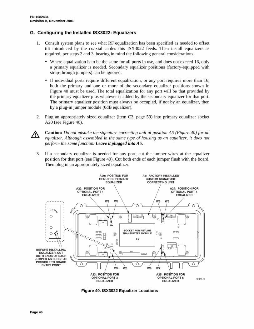
G. Configuring the Installed ISX3022: Equalizers
1. Consult system plans to see what RF equalization has been specified as needed to offsettilt introduced by the coaxial cables this ISX3022 feeds. Then install equalizers asrequired, per steps 2 and 3, bearing in mind the following general considerations.
Where equalization is to be the same for all ports in use, and does not exceed 16, onlya primary equalizer is needed. Secondary equalizer positions (factory-equipped withstrap-through jumpers) can be ignored.
If individual ports require different equalization, or any port requires more than 16,both the primary and one or more of the secondary equalizer positions shown inFigure 40 must be used. The total equalization for any port will be that provided bythe primary equalizer plus whatever is added by the secondary equalizer for that port.The primary equalizer position must always be occupied, if not by an equalizer, thenby a plug-in jumper module (0dB equalizer).
2. Plug an appropriately sized equalizer (item C3, page 59) into primary equalizer socketA20 (see Figure 40).
Caution: Do not mistake the signature correcting unit at position A5 (Figure 40) for anequalizer. Although assembled in the same type of housing as an equalizer, it does notperform the same function. Leave it plugged into A5.
3. If a secondary equalizer is needed for any port, cut the jumper wires at the equalizerposition for that port (see Figure 40). Cut both ends of each jumper flush with the board.Then plug in an appropriately sized equalizer.
Figure 40. ISX3022 Equalizer Locations

PN 1082434Revision B, November 2001
Page 47
H. Configuring the Installed ISX3022: Pads and Terminators (Forward Path)
1. The ISX3022 RF tray motherboard contains five sockets for plug-in attenuator pads usedto adjust forward path RF levels. In certain configurations, some of these sockets mayinstead require a plug-in 75-Ohm terminator. Figure 3 (page 5) shows the functionalpositions of these sockets in block diagram form. Figure 41 shows their physicallocations on the circuit board. Table 3 (page 18) lists all possible port configurations andshows where a pad or terminator is required for each. Where a pad is indicated,determine the rating needed per step 2 or steps 3 through 10, as applicable, bearing inmind the following general considerations.
A pad must always be installed in master forward-path socket A4. The value of thispad should be chosen to attenuate the RF signal received from the lid to the +20dBmVlevel considered optimum for input to forward path primary amplifier stage U2. (Thatequates to +22dBmV at tray motherboard input connector J25 with a 0dB padinstalled in socket A4.)
A pad must be installed in the forward-path socket for each port in use. Pad valueshould be chosen to attenuate individual port amplifier output as needed to give thelevel desired (typically about +44dBmV) at the coaxial cable connected to that port.
Where Table 3 shows that a particular port configuration requires a terminator in apad socket, the terminator ensures that a currently unused internal circuit element orconnection point will not degrade signal quality elsewhere.
Where Table 3 says “Leave empty” for a pad socket, it’s because the socket is isolatedin that port configuration. Plugging in either a terminator or a pad will have no effecton ISX3022 operation.
2. Figure 42 summarizes the RF output levels that ISX3022 receiver modules deliver fortypical optical inputs. Figure 43 shows nominal node losses and gains from receiveroutput (in any available configuration) to a typical port connection (port 4 is shown;ports 1, 3, and 6 are similar). Taken together, this information enables a preliminarydetermination of pad values based on system plans alone, with neither AC power nor anoptical input signal needed. For example, consider the case of a single high-gain opticalreceiver installed in the node, to receive a 112 channel optical input from an 870 MHztransmitter in an HWX equipment shelf. Then:
The “High-Gain Receiver Module” chart of Figure 42 shows that a 0dBm opticalinput in this case can be expected to give a receiver RF output level of about+25.5dBmV. (Node performance specifications are based on a 0dBm optical input.It’s therefore best to base preliminary pad values on a 0dBm input unless systemdesign and node location clearly make that input level impossible to achieve.)
Figure 43 shows that the fixed losses between receiver output and the input to primaryamplifier U2 total about 3dB. Because that 3dB of unavoidable built-in attenuationwill reduce the receiver’s +25.5dBmV output to +22.5dBmV, a 2.5dB pad should beused in socket A4 to get the +20dBmV wanted at U2.
Figure 43 further shows that, if this is a fully enabled four-port node, there is apotential net gain of 29dB from U2 input through to the port 4 connection point. Thatwould increase the +20dBmV signal entering U2 to a +49dBmV output signal at port
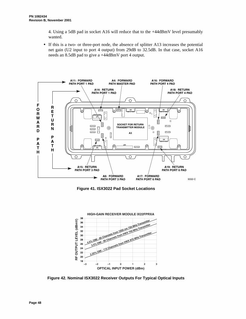
PN 1082434Revision B, November 2001
Page 48
4. Using a 5dB pad in socket A16 will reduce that to the +44dBmV level presumablywanted.
If this is a two- or three-port node, the absence of splitter A13 increases the potentialnet gain (U2 input to port 4 output) from 29dB to 32.5dB. In that case, socket A16needs an 8.5dB pad to give a +44dBmV port 4 output.
Figure 41. ISX3022 Pad Socket Locations
Figure 42. Nominal ISX3022 Receiver Outputs For Typical Optical Inputs

PN 1082434Revision B, November 2001
Page 49
Figure 43. Nominal RF Losses/Gains in ISX3022 Forward Path
3. When AC power and the intended optical input are available, pad values can be adjustedmore precisely to actual system and node operating conditions. First, perform step 4and/or steps 5 through 6 to confirm that an appropriate signal is being delivered to theoptical receiver.
4 Using a digital voltmeter, check the voltage between the active receiver module’s COMand IPD test points. This voltage is derived from IPD (photodiode current) such that areading of 1 V represents 1mW (0dBm) of received optical power:
10 Log (IPD reading in volts) = (Received optical power in dBm)
The optimum IPD reading is 1.0 V (0dBm). Readings between 0.5 V (–3dBm) and 2.0 V(+3dBm) are acceptable for the high-gain receivers. While it is possible to operate with areading as low as 0.2 V (–7dBm), perform step 5 following any reading of less than 0.5V to be sure the optical signal is not accidentally being attenuated at the receiver input.Also check system design to verify the intended optical input level.

PN 1082434Revision B, November 2001
Page 50
Figure 44. ISX3022 Test Point Locations (All –20dB)
Warning: To avoid exposure to laser radiation, do not look into the end of any opticalfiber or bulkhead connector. Infrared radiation is invisible and can seriously damage theretina of the eye.
5. Disconnect the connector on the end of the incoming forward-path fiber from thereceiver’s bulkhead adapter. Perform the procedure of Section 4.C (page 27) forconnector cleaning. Then connect the fiber to an optical power meter and note thepower-level reading obtained.
If the observed power level is less than –7dBm, take whatever steps are necessaryupstream to increase the optical power input available to the receiver module to atleast –7dBm, and if possible, to about 0dBm.
If the observed power level is greater than +3dBm for input to a high-gain receiver,obtain an in-line optical attenuator that will reduce signal level to about 0dBm. Cleanthe attenuator and the bulkhead adapter per Section 4.C (page 27) and install theattenuator in the adapter.
6. Disconnect the incoming fiber from the power meter and reconnect the fiber to thebulkhead adapter (or to the attenuator just installed in the adapter).
7. Connect a spectrum analyzer or signal level meter to primary forward-path test pointconnector J7 (Figure 44).

PN 1082434Revision B, November 2001
Page 51
Note: The signal level observed at any ISX3022 F-connector test point is at –20dB withrespect to the actual RF signal at that point in the node.
8. With a known-good optical signal being received, note the level of a mid-frequency oraverage-strength signal component. Install a pad in primary forward-path pad socket A4that will reduce the level of that component to +22dBmV (+2dBmV as observed on thespectrum analyzer or signal level meter).
9. For each active port in turn, move the spectrum analyzer or signal level meter connectionto the forward-path test point connector for that port (Figure 44). Plug a 0dB pad into theforward-path pad socket for that port (Figure 41) and note the level of the referencesignal component used in step 8. Replace the 0dB pad with one that will reduce that levelto the output level wanted for that port.
10. As an alternative to using a received optical signal for the test source when checkingindividual port RF levels per step 9 (or performing downstream system tests), a sweepsignal may be injected at connector J8 (Figure 44). Note from Figure 43 that with a 0dBpad in A4 the sweep signal reaching primary amplifier U2 through the primary equalizerwill be at a level about 21dB down from that applied to J8. To avoid interference withthe sweep signal during such testing, temporarily disconnect from the receiver—andimmediately cap—the fiber carrying any incoming optical signal.
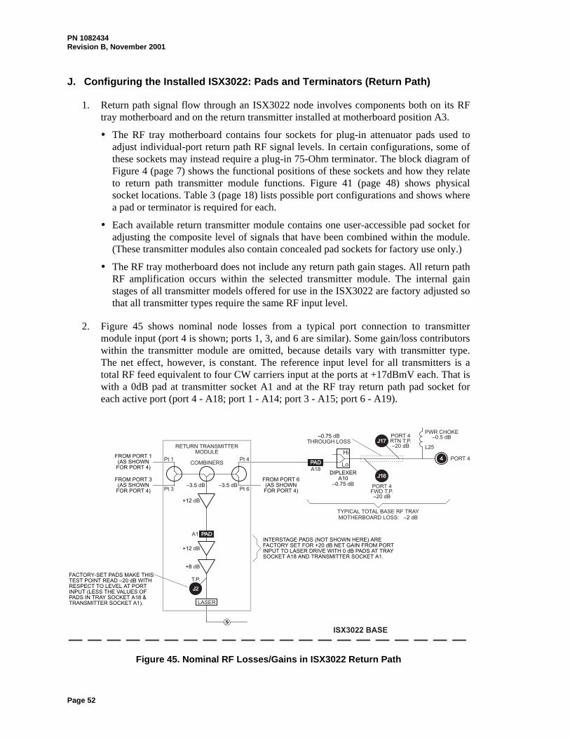
PN 1082434Revision B, November 2001
Page 52
J. Configuring the Installed ISX3022: Pads and Terminators (Return Path)
1. Return path signal flow through an ISX3022 node involves components both on its RFtray motherboard and on the return transmitter installed at motherboard position A3.
The RF tray motherboard contains four sockets for plug-in attenuator pads used toadjust individual-port return path RF signal levels. In certain configurations, some ofthese sockets may instead require a plug-in 75-Ohm terminator. The block diagram ofFigure 4 (page 7) shows the functional positions of these sockets and how they relateto return path transmitter module functions. Figure 41 (page 48) shows physicalsocket locations. Table 3 (page 18) lists possible port configurations and shows wherea pad or terminator is required for each.
Each available return transmitter module contains one user-accessible pad socket foradjusting the composite level of signals that have been combined within the module.(These transmitter modules also contain concealed pad sockets for factory use only.)
The RF tray motherboard does not include any return path gain stages. All return pathRF amplification occurs within the selected transmitter module. The internal gainstages of all transmitter models offered for use in the ISX3022 are factory adjusted sothat all transmitter types require the same RF input level.
2. Figure 45 shows nominal node losses from a typical port connection to transmittermodule input (port 4 is shown; ports 1, 3, and 6 are similar). Some gain/loss contributorswithin the transmitter module are omitted, because details vary with transmitter type.The net effect, however, is constant. The reference input level for all transmitters is atotal RF feed equivalent to four CW carriers input at the ports at +17dBmV each. That iswith a 0dB pad at transmitter socket A1 and at the RF tray return path pad socket foreach active port (port 4 - A18; port 1 - A14; port 3 - A15; port 6 - A19).
Figure 45. Nominal RF Losses/Gains in ISX3022 Return Path

PN 1082434Revision B, November 2001
Page 53
3. If the planned actual return path load does closely approximate a few NTSC videocarriers, the +17dBmV level for each of four carriers readily converts to equivalentlevels for each of other numbers of carriers (levels rounded to whole numbers):
Formula: X = 17 + 10 * log(4/Y)
Number of carriers (Y) Level for each carrier (X) 1 +23dBmV2 +20dBmV3 +18dBmV4 +17dBmV5 +16dBmV6 +15dBmV
As an example of setup in such a case, assume that there will be three carriers, onearriving at port 3 at +21dBmV and the other two coming to port 6 at +20dBmV each.Knowing from above that +18dBmV each is what’s wanted for each of three carriers, wecould use a 3dB pad in port 3 socket A15 and a 2dB pad in port 6 socket A19, with a0dB pad in the transmitter socket. Looking at the composite signal at transmitter testpoint J2, we should then see three carriers, each measuring –2dBmV (21 – 20 –3 for theport 3 carrier; 20 – 20 – 2 for each of the port 6 carriers.
4. Consider, however, that forward and return path composite signals may differ in animportant way. Most of the forward path payload is its large block of video channels.That’s why basing forward path configuration primarily on video channel loading makessense. But the return path payload may well not be so clearly dominated by one signaltype. With mixed signal types to transmit, a better approach may be to allocatetransmitter capacity according to the needs of the various signals to be passed. The firststep in that process is to determine just what the signal mix will be and how much of theavailable bandwidth it will actively use.
Considering all ports whose return path inputs will be combined in the transmitter,record the bandwidth of each signal type expected and how many signals of each typethere will be.
Signal bandwidth: As the bandwidth for each signal to be carried, use that signaltype’s full channel spacing (including guard bands), not just its noise bandwidth.
Number of signals of each type: Count only signal channels that will actually be used.Do not include any frequency bands that are not yet to be used, that are reserved forfrequency hopping, or that will be left empty because of expected ingress.
Example: Total planned payload:
Signal Type Signal Bandwidth Number of Signals FSK 200 kHz 17
NTSC Video 6 MHz 1QPSK 2 MHz 6
5. Next, calculate the total bandwidth used (BWTOTAL USED) by summing the individual signalbandwidths compiled per step 4 above.

PN 1082434Revision B, November 2001
Page 54
Example: BWTOTAL USED = 17 * 200 kHz + 6 MHz + 6 * 2 MHz = 21.4 MHz
6. Next, calculate desired RF power density (PD) in dBmV per Hz, using the BWTOTAL USED
figure determined per step 5 above and a RECOMMENDED TOTAL RF INPUT value. For anISX3022 return transmitter, RECOMMENDED TOTAL RF INPUT (at ports) is the 1-carrierlevel from step 3, or +23dBmV.
Formula: PD = RECOMMENDED TOTAL RF INPUT – 10 * log(BWTOTAL USED)
Example: Continuing from step 5:
PD = +23dBmV – 10 * log(21,400,000 Hz) = –50.3dBmV/Hz
7. Now calculate the RF level wanted for each signal of each type (LVLST), using the PD
figure determined per step 6 above and the bandwidth figure for each signal type (BWST)recorded per step 4.
Formula: LVLST = PD + 10 * log(BWST)
Example: Continuing from steps 4 and 6 above:
LVLST for FSK signals = –50.3dBmV/Hz + 10 * log(200,000 Hz) = +2.7dBmVLVLST for video signal = –50.3dBmV/Hz + 10 * log(6,000,000 Hz) = +17.5dBmVLVLST for QPSK signals = –50.3dBmV/Hz + 10 * log(2,000,000 Hz) = +12.7dBmV
8. To check that steps 5 through 7 were performed correctly, logarithmically sum theindividual input signal levels from step 7. The result should be the RECOMMENDED
TOTAL RF INPUT value (PRT).
Formula: PRT = 10 * log(10S1LVL/10 + 10S2LVL/10 + 10S3LVL/10 + ...)
Example: Continuing with values from steps 4 and 7 above:
PRT = 10 * log(17 * 10+2.7/10 + 10+17.5/10 + 6 * 10+12.7/10) = +23dBmV
9. Compare the values from step 7 with the planned or measured values for each signal typearriving at each port.
Where the arriving value is higher than the step 7 value, the value difference is thesize of pad to be used for that port.
If an arriving value is equal to or slightly lower than the step 7 value, use a 0dB padfor that port. If an arriving value is significantly (more than about 2dB) lower than thestep 7 value, the signal source output level should be increased.
Where the composite arriving at a port contains more than one signal type, valuecomparison results may vary by signal type. If the variations are small, use acompromise pad value that falls between the high and low value differences. If thevalue differences vary by more than about 2dB, it may be advisable to change the RFoutput level at one or more of the return path signal sources.

PN 1082434Revision B, November 2001
Page 55
K. Closing the Configured ISX3022
Note: Close the ISX3022 enclosure whenever it will be left unattended, to keep moistureand dirt out of the interior.
1. After completing ISX3022 configuration (and any desired system testing requiring fullaccess to the opened node), replace the cover over the RF tray if it was removed (seeFigure 6, page 17).
2. Remove any leftover work materials or scraps from the interior of the enclosure. If anymoisture collected in the enclosure during installation, use a clean lint-free cloth to wipethe interior dry.
3. Close the lid assembly, align it squarely with the base assembly, and thread all six lidbolts finger-tight to hold the lid in place. Make certain that the lid sits evenly on the casegasket and that the lid bolts are not cross-threaded.
4. Following the pattern shown in Figure 46, tighten the lid bolts in gradual steps to thefinal torque shown. Check the seating of the lid on the gasket while tightening each bolt.
Note: Use a torque wrench or other wrench designed to apply only the specified torque.Using the wrong tool may result in excess torque being applied to the lid bolts.
Figure 46. Torque Pattern for Housing Closure Bolts

PN 1082434Revision B, November 2001
Page 56
(This page intentionally blank)

PN 1082434Revision B, November 2001
Page 57
5. PARTS LIST
5.01 This section identifies parts and supply items that may be ordered from C-COR.net asneeded to support installation and maintenance of ISX3022 units.
9571-B
65
4
A1
A5 A6
A4
A10
A2 (6 PLACES)
(2 PLACES)
(2 PLACES)
(2 PLACES)
(10 PLACES)
(4 PLACES)
(1 TO 5 PLACES,AS NEEDED)
A3
A7
A8 A9
Figure 47. Locations of ISX3022 Parts Listed in Table 4
Table 4. ISX3022 Parts Shown in Figure 47
KEY NO. ITEM DESCRIPTION PART NO.
A1 Housing closure bolt with anti-seize coating 1031539
A2 Spring for housing closure bolt 32101-9880
A3 Strand clamp bolt - stainless steel 002429-001
Stainless steel bolt kit (6 of A1, 2 of A3) HWISXBOLTKIT01
A4 Strand-mount clamp - uncoated.............................................- corrosion protected ............................
002884-001002884-002
A5 Port cap with chain (includes O ring) 091143-001
A6 Drive screw for 0.104-in. hole, to attach A5 cap chain tobase casting
30148-0401
A7 Port cap without chain (includes O ring) 091143-003
A8 Threaded entry port fitting 002258-001
A9 Insulating bushing (behind A8 in base casting cavity) 002293-001
A10 Threaded entry port fitting 002258-002
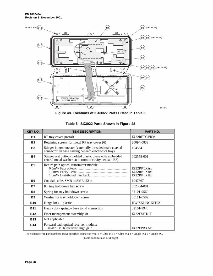
PN 1082434Revision B, November 2001
Page 58
Figure 48. Locations of ISX3022 Parts Listed in Table 5
Table 5. ISX3022 Parts Shown in Figure 48
KEY NO. ITEM DESCRIPTION PART NO.
B1 RF tray cover (metal) IX22RFTCVRM
B2 Retaining screws for metal RF tray cover (6) 30094-0832
B3 Stinger interconnector (externally threaded male coaxialconnector, in base casting beneath electronics tray)
1045841
B4 Stinger rest button (molded plastic piece with embeddedcentral metal washer, at bottom of cavity beneath B3)
002558-001
B5 Return path optical transmitter module:0.5mW Fabry-Perot .........................................................1.0mW Fabry-Perot .........................................................1.0mW Distributed Feedback...........................................
IX22RPTXAxIX22RPTXBxIX22RPTXHx
B6 Coaxial cable, SMB to SMB, 22 in. 1047367
B7 RF tray holddown hex screw 002304-001
B8 Spring for tray holddown screw 32101-9560
B9 Washer for tray holddown screw 30111-0502
B10 Hinge lock – plastic HWISXHNGKIT02
B11 Heavy duty spring – base to lid connection 32101-9940
B12 Fiber management assembly kit IX22FMTKIT
B13 Not applicable
B14 Forward path optical receiver module:40-870 MHz receiver, high gain........................................ IX22FPRXAx
The x character in part numbers above specifies connector type: 1 = Ultra FC; 3 = Ultra SC; 4 = Angle FC; 6 = Angle SC.
(Table continues on next page)

PN 1082434Revision B, November 2001
Page 59
Table 5. ISX3022 Parts Shown in Figure 48 (Continued)
KEY NO. ITEM DESCRIPTION PART NO.
B15 EMI-shielding gasket 002260-001
B16 Base-to-lid interconnecting ribbon cable 1049424
B17 Environmental gasket 002225-001
B18 Housing closure insert, tapered, internally threaded 002637-001
Figure 49: Locations of ISX3022 Parts Listed in Table 6
Table 6. ISX3022 Parts Shown in Figure 49
KEY NO. ITEM DESCRIPTION PART NO.
C1 Terminator, 75 Ohm, plug-in .................................................Attenuator pads, plug-in, 0db - 20dB in 0.5dB increments
1.2” x 0.5” x 0.23”. Examples:0dB pad .........................................................................1.5dB pad ......................................................................
IPADTERMIPADxxx (xxx = 000 - 200)
Examples:IPAD000IPAD015
C2 Clear plug-in I-pad attenuator/terminator guide 002846-001
C3 Equalizers, plug-in:0dB (req’d for A20 if no primary slope control wanted;
also for A22-A25 to eliminate port slope control onceW1-W8 jumpers have been cut away)
54 – 870 MHz.............................................................54 – 750 MHz.............................................................
Equalizers, 54 – 870 MHz, 1 - 14dB in 1dB incrementsEqualizers, 54 – 750 MHz, 1 - 16dB in 1dB increments
IX8EQ00IX7EQ00IX8EQxx (xx = 01 – 14)IX7EQxx (xx = 01 – 16)
(Table continues on next page)
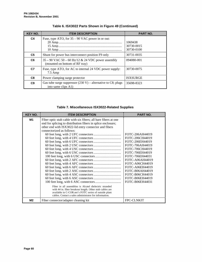
PN 1082434Revision B, November 2001
Page 60
Table 6. ISX3022 Parts Shown in Figure 49 (Continued)
KEY NO. ITEM DESCRIPTION PART NO.
C4 Fuse, type ATO, for 35 – 90 VAC power in or out:20 Amp............................................................................15 Amp............................................................................10 Amp............................................................................
106943830730-001530730-0100
C5 Shunt for power bus interconnect position F9 only 30731-0035
C6 35 – 90 VAC 50 – 60 Hz/12 & 24 VDC power assembly(mounted on bottom of RF tray)
094080-001
C7 Fuse, type ATO, for AC to internal 24 VDC power supply:7.5 Amp
30730-0075
C8 Power clamping surge protector ISXSURGE
C9 Gas tube surge suppressor (230 V) – alternative to C8; plugsinto same clips A1)
35698-8323
Table 7. Miscellaneous ISX3022-Related Supplies
KEY NO. ITEM DESCRIPTION PART NO.
M1 Fiber optic stub cable with six fibers; all bare fibers at oneend for splicing to distribution fibers in splice enclosure;other end with ISX3022-lid entry connector and fibersconnectorized as follows:
60 feet long, with 2 UFC connectors .................................60 feet long, with 4 UFC connectors .................................60 feet long, with 6 UFC connectors .................................60 feet long, with 2 USC connectors .................................60 feet long, with 4 USC connectors .................................60 feet long, with 6 USC connectors .................................100 feet long, with 6 USC connectors ...............................60 feet long, with 2 AFC connectors .................................60 feet long, with 4 AFC connectors .................................60 feet long, with 6 AFC connectors .................................60 feet long, with 2 ASC connectors .................................60 feet long, with 4 ASC connectors .................................60 feet long, with 6 ASC connectors .................................100 feet long, with 6 ASC connectors ...............................
Fiber in all assemblies is Alcatel dielectric strandedwith 44 in. fiber breakout length. Other stub cables areavailable in C-COR.net’s FOTC series of outside plantcables. Contact a sales administrator for information.
FOTC-206AH44019FOTC-206CH44019FOTC-206EH44019FOTC-706AH44019FOTC-706CH44019FOTC-706EH44019FOTC-706EH44031FOTC-A06AH44019FOTC-A06CH44019FOTC-A06EH44019FOTC-B06AH44019FOTC-B06CH44019FOTC-B06EH44019FOTC-B06EH44031
M2 Fiber connector/adapter cleaning kit FPC-CLNKIT


European OfficeP.O. Box 10.2651301 AG AlmereThe NetherlandsTel: +31-36-5461111 Fax: +31-36-5364255
Canadian Office981 Mountview Court, Oshawa,Ontario, L1K 2M1, CanadaTel: 905-427-0366 Fax: 905-428-0927800-427-2559 (Toll free for Canadian call only)
World Headquarters60 Decibel RoadState College, PA 16801-7580 USATel: 800-233-2267, +1-814-238-2461 Fax: +1-814-238-4065www.c-cor.net