optimum design of new 25a-size metal gasket …ijmo.org/papers/26-t0173.pdf25a-size metal gasket for...
TRANSCRIPT
Abstract—In the previous study, the limits of contact width of
25A-size metal gasket for no leakage can be chosen. The optimized gasket shape can be developed by increasing of contact width. In this study, a 25A-size metal gasket shape was optimized based on contact width as design concept and considering plastic contact stress. The design of experimentation (DOE) Taguchi method is used to analyse the effect of each parameter design and predict optimal design of new 25A-size metal gasket. The L18 orthogonal array was concerned to design experimental matrix for seven factors with three levels. The optimum design is chosen due to assumption that the better sealing performances are desirable because of the large contact stress. The optimum gasket design is the model with OH = 3 mm, p1 = 3.5 mm, p2 = 4.5 mm, p3 = 4.5 mm, t = 1.8 mm, R = 1.5 mm and h = 0.3 mm.
Index Terms—plastic contact stress, 25A-size metal gasket, optimum design, Taguchi method.
I. INTRODUCTION The gasket alternative research challenge comes from the
decision to ban the use asbestos in the Japan from the beginning of 2008. One of gasket alternative for asbestos substitution is metal gasket. Metal gasket is chosen due to several advantages such as its high heat and chemical resistance, capability to withstand pressure, recyclability, and most importantly its reliability in critical situations. However, there is another important requirement, except for optimizes gasket performance, which is reducing clamping load. Based on this requirement, the corrugated metal gasket, with a small contact area, is preferred to obtain a low loading metal gasket.
Saeed, et.all [1] proposed a new 25A-size metal gasket which uses corrugated shape. The gasket has metal spring effect and produces high local contact stress to create sealing line with flanges. The result confirmed that the contact stress and contact width were an important design parameter to optimize the 25A-size metal gasket performance. However the value of contact width as design parameter is not defined yet. Other papers also evaluated contact width in rubber lips
Manuscript received April 5, 2011; revised May 24, 2011. This work was
supported in part by the Strength of Material laboratory, Yamaguchi University Japan.
Moch Agus Choiron is doctoral student at Mechanical Engineering in Yamaguchi University and lecture in Brawijaya University Indonesia (e-mail: [email protected], agus_choiron`ub.ac.id).
Shigeyuki Haruyama, is Associate Professor at Graduate School of Innovation and Technology Management, Yamaguchi University, Japan (e-mail: haruyama@ yamaguchi-u.ac.jp).
Ken Kaminishi is Professor at Graduate School of Innovation and Technology Management, Yamaguchi University, Japan (e-mail: kaminisi@ yamaguchi-u.ac.jp).
seals [2-3] and PTFE lips seals [4], but the relationship between contact width and leakage for design concept did not examined yet. Haruyama S. et.all [5] continues the Saeed research. The limits size of contact width as gasket design parameter was investigated. Comparing the evaluation results of the relationship between the clamping load of the flange and the contact width by using the FEM analysis with the experimental results of the clamping load and the leakage, the contact width which has no leak in the new 25A-size metal gasket was clarified [5]. Based on this result, contact width can be used as a main parameter to optimize the gasket design. The leakage can be reduced with increasing the contact width.
Bossak [6] studied a new approach called Simulation Based Design (SBD) which produce lower lifecycle costs, reduce design cycle and development time and improve product performance. SBD is developed approach for collaborative, distributed design and virtual product development. The concept of SBD is similar with Analysis Led Design (ALD). In developing precision mechanical products such as gasket, going through multiple build-and-test prototype cycles to verify performance for leakage is expensive and time-consuming. This issue can be reduced by evaluating and refining designs, so fewer test cycles will be needed later in development. ALD can shorten product development time by getting designs right the first time [7]. Now when a new gasket design is being developed, a series of repetitions are done through simulation until the gasket performance meets the design limits.
In this study, optimum design of a new 25A-size metal gasket considering plastic contact stress was investigated. Based on plastic contact stress consideration on contact width, the optimized gasket is chosen by using balancing between contact width and contact stress. The design of experiments (DOE) Taguchi method is used to investigate the factor effect on the contact width and predict the optimal design. The seven factors are overhang (OH), pitch 1, pitch 2, pitch 3 (p1, p2, p3), thickness (t), radius (R), and lip height (h). The L18 orthogonal array was built to design experimental matrix for seven factors with three levels.
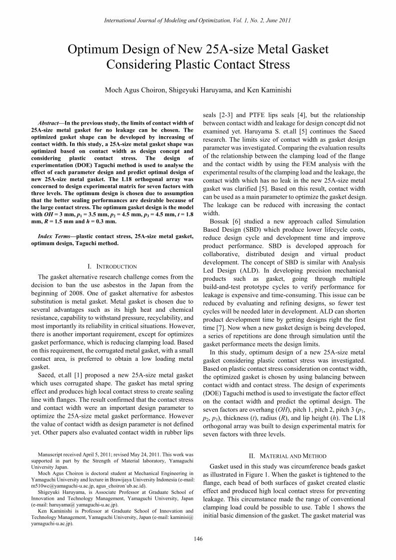
II. MATERIAL AND METHOD Gasket used in this study was circumference beads gasket
as illustrated in Figure 1. When the gasket is tightened to the flange, each bead of both surfaces of gasket created elastic effect and produced high local contact stress for preventing leakage. This circumstance made the range of conventional clamping load could be possible to use. Table 1 shows the initial basic dimension of the gasket. The gasket material was
Optimum Design of New 25A-size Metal Gasket Considering Plastic Contact Stress
Moch Agus Choiron, Shigeyuki Haruyama, and Ken Kaminishi
International Journal of Modeling and Optimization, Vol. 1, No. 2, June 2011
146

SUS304 due to its effectiveness in high-temperature and high-pressure environment. In order to ensure the properties of the material, SUS304 was initially validated using tensile test carried out based on JISZ2241 [8]. From the tensile test result, the nominal stress (σ) of SUS304 was 398.83 MPa, the modulus of the elasticity (E) was 210 GPa and the tangent modulus was 1900.53 MPa.
Figure 1. The initial gasket cross section and design parameters
TABLE 1. INITIAL BASIC DIMENSIONS OF THE GASKET
Design Parameter Dimension [mm] 1. Inner radius (r) 17.5 2. Overall length (fixed) 19.5 3. Over hang (OH) 4.5 4. Lip height (h) 0.4 5. Thickness (t) 1.45 6. Convex radius (R) 2 7. Pitch (p1 = p2 = p3) 3
The contact width modeling was undertaken using finite
element method (FEM) analysis software MSC. Marc [9]. The flange was assumed as rigid body in both sides. Using two dimensional assumptions, axisymmetric model was made to adopt compression displacement in axial direction on gasket in between the top and the bottom of the flange (Figure 2). In the previous study, Prescale pressure sensitive paper was done in order to get a validation of contact width measurement. The validation contact width results indicate similar trend data between simulation and experimental result [10]. For contact width measurement, only at the beads (convex section) of gasket which is effective for avoiding leak is taken as evaluation part.
Figure 2. Schematic section of physical model and axisymmetric model
Based on previous study, the plastic contact stress built
sealing lines between flange and gasket to avoid leakage, although the value is not yet defined clearly. In this study, optimization design based on the increasing contact width is combined with considering contact stress. The optimum design is also determined based on reducing the clamping load. It can be denote by using the slope or gradient of the curve of relationship between contact width and clamping load. The slope of curve is increased; it will be reduce the clamping load. Due to the optimization design based on increasing contact width is combined with considering contact stress. The gasket design with higher slope is choose
as optimum design as shown in the figure 3.
Figure 3. The gasket design with higher slope is choose as optimum
design
From MSC Marc result, the contact width is determined based on contact status. Contact status values are 1 and 0 which mean contact and no contact, respectively. This status is done without considering the distribution of the contact stress. This condition is called as gasket design number 1. Moreover, the gasket design number 2 is done by deleting the contact stress value below of 400 MPa. It was found from the material properties, the yield stress is 398.83 MPa. Therefore, contact width value is more reduced due to contact width with contact stress below of 400 MPa is deleted. This procedure is done based on assumption which the large contact stress creates sealing lines on contact width [11]. Figure 4 show the distribution of contact stress and contact width measurement after gasket deformation.
Figure 4. The distribution of contact stress and contact width measurement
after gasket deformation
In this study, the Taguchi DOE method was used to evaluate the effect of each parameter design and predict optimal design of new 25A-size metal gasket. Taguchi method uses a special set of arrays called orthogonal arrays. These standard arrays stipulate the way of conducting the minimal number of experiments, which could give the full information of all the factors that affect the performance parameters [12]. The following Tables 2 and 3 show the Taguchi test matrix for the tests. To design experimental matrix for eight factors with three levels, the L18 orthogonal array was most applicable.
The Taguchi method can be applied on simulation experiment, is becoming as a popular as actual experiments. Simulation result yields no error in repeatability but has problem on error modeling. Therefore, it becomes a
Contact width
Higher slope as optimum design
International Journal of Modeling and Optimization, Vol. 1, No. 2, June 2011
147

challenge of determining how to integrate these so-called noise factors into the model. A statistic cause and effect model describing the relationship between responses, parameter and noise factor will be the key to a solution [13].
TABLE 2. FACTOR AND LEVEL DESCRIPTIONS Factor Factor Description Level
1 Level
2 Level 3
A Over Hang (OH) 3 4 - B Pitch 1 (p1) 3.5 4.0 4.5 C Pitch 2 (p2) 3.5 4.0 4.5 D Pitch 3 (p3) 3.5 4.0 4.5 E Thickness (t) 1.2 1.5 1.8 F Radius (R) 1.5 2.5 3.5 G Lip height (h) 0.30 0.35 0.40 H Error 1 2 3
TABLE 3. L18 TEST MATRIX
Trial Factor A B C D E F G H
1 1 1 1 1 1 1 1 1 2 1 1 2 2 2 2 2 2 3 1 1 3 3 3 3 3 3 4 1 2 1 1 2 2 3 3 5 1 2 2 2 3 3 1 1 6 1 2 3 3 1 1 2 2 7 1 3 1 2 1 3 2 3 8 1 3 2 3 2 1 3 1 9 1 3 3 1 3 2 1 2
10 2 1 1 3 3 2 2 1 11 2 1 2 1 1 3 3 2 12 2 1 3 2 2 1 1 3 13 2 2 1 2 3 1 3 2 14 2 2 2 3 1 2 1 3 15 2 2 3 1 2 3 2 1 16 2 3 1 3 2 3 1 2 17 2 3 2 1 3 1 2 3 18 2 3 3 2 1 2 3 1
III. RESULT AND DISCUSSION Although parameter factors affect the gasket performance
is obtained, but with conventional design concept, after gasket design is created, it require evaluation analysis going through multiple build and test to verify performance. Therefore redesign is expensive and time-consuming. With new concept design, redesign will be eliminated with a series simulation by modify and optimized which validated baseline computer modeling, until geometry and material that achieved target of design is done. This is main idea of upfront engineering and ALD (Figure 5).
To compute the main effect of each factor, the result for trials of the factor is added and then divides by the number of such trials [14]. In example for A1, the column for A is observed that the level 1 occurs in the experiment number 1 until 9. The main effect of A1 is calculated by adding the results (Y) of those nine trials and then divides by nine as a number of trials. The main effects of other factors are computed in similar manner. Figure 6 and 7 shows the main effects is plotted for a visual inspection of each factor for various level conditions at gasket design No. 1 and No. 2, respectively. It denotes that thickness and radius have a stronger influence on the observed value at gasket design No. 1. Thickness and pitch number 1 have a stronger influence on the observed value at gasket design No. 2.
Figure 5. Comparing between conventional design and new design concept
The L18 matrix was conducted and the slope of the curve
of relationship between contact width and clamping load as observed values (Y) was calculated by using FEM analysis as shown in the Table 4.
TABLE 4. THE L18 TEST MATRIX AND THE RESULTS
Trial Factor
Slope of curve (Y) Gasket design No. 1
Gasket design No. 2
1 A1B1C1D1E1F1G1H1 0.0096 0.0076 2 A1B1C2D2E2F2G2H2 0.0097 0.0072 3 A1B1C3D3E3F3G3H3 0.0101 0.0077 4 A1B2C1D1E2F2G3H3 0.0092 0.0065 5 A1B2C2D2E3F3G1H1 0.0092 0.0069 6 A1B2C3D3E1F1G2H2 0.0094 0.0065 7 A1B3C1D2E1F3G2H3 0.0138 0.0053 8 A1B3C2D3E2F1G3H1 0.0083 0.0065 9 A1B3C3D1E3F2G1H2 0.0082 0.0064 10 A2B1C1D3E3F2G2H1 0.0083 0.0068 11 A2B1C2D1E1F3G3H2 0.0140 0.0050 12 A2B1C3D2E2F1G1H3 0.0081 0.0064 13 A2B2C1D2E3F1G3H2 0.0073 0.0061 14 A2B2C2D3E1F2G1H3 0.0110 0.0059 15 A2B2C3D1E2F3G2H1 0.0106 0.0068 16 A2B3C1D3E2F3G1H2 0.0104 0.0064 17 A2B3C2D1E3F1G2H3 0.0071 0.0061 18 A2B3C3D2E1F2G3H1 0.0111 0.0051
Figure 6. The main effects of each factor for various levels at slope of curve
on gasket design No. 1
TABLE 5. OPTIMUM GASKET DESIGN AT NO. 1 AND NO. 2
Factor Level Description
Optimum design No. 1
Optimum design No. 2
OH 4 mm 3 mm p1 3.5 mm 3.5 mm p2 4.0 mm 4.5 mm p3 4.0 mm 4.5 mm t 1.2 mm 1.8 mm R 3.5 mm 1.5 mm h 0.4 mm 0.3 mm
International Journal of Modeling and Optimization, Vol. 1, No. 2, June 2011
148

In addition, the optimum design of gasket based on results of each of the observed values is illustrated in Table 5. The schematic of the optimum gasket cross section is shown in Figure 8.
Figure 7. The main effects of each factor for various levels at slope of curve
on gasket design No. 2
(a)
(b)
Figure 8. The optimum gasket cross section at gasket design: (a) No. 1; (b) No. 2
The result of relationship between the contact width and clamping load, both of optimum designs No. 1 and initial design are shown in the Figure 9. The higher slope of the curve for the optimized design shows a higher functionality and hence higher robustness [1]. The result show that even at low clamping load, the optimized design at No.1 provides a marked improvement on the initial design [10]. The level range of load between 80 kN and 100 kN shows that the optimum design at No. 1 can reduce the clamping load. The level range of load is improved compared with the initial design which the condition of no leak occurred on 100 kN clamping load.
Figure 9. The relationship between the contact width and clamping load at
initial standard and optimum design No. 1
Figure 10 shows comparison optimum design No. 1 and No. 2 by condition that contact width with contact stress below of 400 MPa is deleted. Based on assumption which the large contact stress creates sealing lines on contact width, slope of the curve for the optimized design No.2 is higher than the optimized design No. 1.
Figure 11 and 12 shows the distribution of contact stress along x-axis position in one of convex section at optimum
design No. 1 and No. 2, respectively. The curves denote that contact stress distribution at No. 2 is larger than contact stress distribution at No. 1, although contact width at No. 2 is smaller than contact width at No. 1.
Figure 10. Comparison optimum design No. 1 and No. 2 by condition that
contact width with contact stress below of 400 MPa is deleted
Figure 11. The distribution of contact stress along x-axis position in one of
convex section at optimum design No. 1
Figure 12. The distribution of contact stress along x-axis position in one of
convex section at optimum design No. 2
For other description about distribution of contact stress on both optimum designs, it can be used a composition of contact stress distribution bar curve as shown in the figure 13, 14 and 15. Each figure show composition of contact stress distribution at 60, 80 and 100 kN load. The yellow color bar show the contact stress distribution more than 400 MPa and the blue color bar show the contact stress distribution 0 - 400 MPa. It denotes that contact stress distribution more than 400 MPa on optimum design No. 2 is larger than contact stress distribution on No. 1. Therefore, the optimum design No. 2 is chosen due to assumption that the better sealing performances are desirable because the large contact stress.
For future study, both of the optimum gaskets at optimum design No. 1 and No. 2 require an experimental confirmation test for the final step in verifying the results drawn based on Taguchi’s design approach.
Contact width
International Journal of Modeling and Optimization, Vol. 1, No. 2, June 2011
149

Figure 13. The distribution of contact stress at 60 kN load on optimum design
No. 1 and No. 2
Figure 14. The distribution of contact stress at 80 kN load on optimum design
No. 1 and No. 2
Figure 15. The distribution of contact stress at 100 kN load on optimum
design No. 1 and No. 2
IV. CONCLUSIONS The L18 orthogonal array of Taguchi method was
implicated to design experimental matrix for seven factors with three levels. Based on plastic contact stress consideration on contact width, the optimized gasket is determined by deleting contact width with contact stress below of 400 MPa. The optimum design is the model with OH = 3 mm, p1 = 3.5 mm, p2 = 4.5 mm, p3 = 4.5 mm, t = 1.8 mm, R = 1.5 mm and h = 0.3 mm.
ACKNOWLEDGEMENTS This project supported by the Strength of Material
laboratory, Yamaguchi University, Japan. The first author wish to thank for scholarship support from the Directorate of Higher Education Indonesia cooperated with Brawijaya University.
REFERENCES [1] Saeed, H.A, Izumi, S., Sakai, S., Haruyama, S., Nagawa, M., Noda, H.,
“Development of New Metallic Gasket and its Optimum Design for Leakage Performance”, Journal of Solid Mechanics and Material Engineering vol. 2, no. 1, 2008, pp. 105-114.
[2] Lee, C.Y., Lin, C.S., Jian, R.Q., Wen, C.Y., “Simulation and experimentation on the contact width and pressure distribution of lip seals, Tribology International”, vol. 39, 2006, pp. 915–920.
[3] Stakenborg, M.J.L., “On the sealing mechanism of radial lip seals”, Tribology International, vol. 21, no. 6, 1988, pp. 335-340.
[4] Weber, D., Haas, W., Wear Behaviors of PTFE Lip Seals with Different Sealing Edge Designs, Experiments and Simulation, Sealing Technology, pp. 7-12, February 2007.
[5] Haruyama S., Choiron M.A, Kaminishi K., A Study of Design Standard and Performance Evaluation on New Metallic Gasket, Proceeding of the 2nd International Symposium on Digital Manufacturing, Wuhan China, September 2009, pp. 107-113.
[6] Bossak, M.A, “Simulation based design”, Journal of Materials Processing Technology, vol. 76, 1998, pp. 8-11.
[7] Tickel, B., “Getting It Right the First Time”, ANSYS Advantage, vol. 1, no. 3, 2007, pp. 10-12.
[8] JIS Z2241, “Method of tensile test for metallic materials”, Japanese Standards Association, 1998.
[9] MSC Marc 2007. User manual. [10] Choiron M.A, Haruyama S., Kaminishi K., “Simulation and
Experimentation on the Contact Width of New Metal Gasket for Asbestos Substitution”, International Journal of Aerospace and Mechanical Engineering, vol. 5, no. 4, 2011, pp. 283-287.
[11] Nao-Aki Noda, Masato Nagawa, Fumitaka Shiraishi, Akifumi Inoue, “Sealing Performance of New Gasketless Flange”, Journal of Pressure Vessel Technology, vol. 124, 2002, pp. 239-246.
[12] Fowlkes, W.Y., Creveling, C.M., “Engineering Methods for Robust Product Design” Massachusetts, MA: Addison Wesley Longman, Inc., 1995.
[13] Yoshino, M., Nishina, K., “SQC and Digital Engineering: Technological Trends in Design Parameter Optimization and Current Issues”, The Grammar Of Technology Development, Part II, 2008, pp. 135-151.
[14] Roy, Ranjit, “A Primer on the Taguchi Method”, Van Nostrand Reinhold, 1990.
Moch. Agus Choiron received his M.S. from Sepuluh November Institute of Technology, Indonesia and B.Sc. from Brawijaya University, Indonesia. He work as a lecture at Mechanical Department, Brawijaya University, Indonesia. He is currently a Dr.Eng candidate at the Graduate School of Science and Engineering, Department of Mechanical Engineering at Yamaguchi University, Japan. Ken Kaminishi received his Dr. Eng of Mechanical Engineering from Kyushu University, Japan, and both his M.S. and B.Sc. from Yamaguchi University, Japan. Professor Ken Kaminishi is currently a Dean of the Graduate School of Innovation & Technology Management, Yamaguchi University. He is the president of Japan MOT Council whose members are all graduate schools of MOT in Japan. He is also the director of Japan MOT Society and the representative of Western Japan MOT Consortium, a tie-up among government-local industry-academia in the Western Japan area. Shigeyuki Haruyama received his Dr.Eng of Mechanical Engineering from Tokyo University of Science, Japan, and both his M.S. and B.Sc. from Kyushu Institute of Technology, Japan. Prof. Haruyama is currently a lecture of the Graduate School of Innovation & Technology Management, Yamaguchi University.
International Journal of Modeling and Optimization, Vol. 1, No. 2, June 2011
150