optimizing the heat treatment process of cast aluminium alloys
TRANSCRIPT
9
Optimizing the Heat Treatment Process of Cast Aluminium Alloys
Andrea Manente1 and Giulio Timelli2 1Cestaro Fonderie Spa
2University of Padova, Department of Management and Engineering Italy
1. Introduction
The unfailing increased use of light alloys in the automotive industry is, above all, due to the need of decreasing vehicle’s weight. The same need has to be taken into account in order to face up also both energetic and environmental requirements (Valentini, 2002). In terms of application rates, Al and its alloys have an advantage over other light materials. The reduced prices, the recyclability, the development of new improved alloys and casting processes, the increased understanding of design criteria and life prediction for stressed components and an excellent compromise between mechanical performances and lightness are the key factors for the increasing demand of Al alloys. A consolidated example of aluminium alloy employment regards the production of wheels, which, together with an improved aesthetic appearance, guarantees an improvement of driving, like directed consequence of the inertia reduction. These critical safety components are somewhat unique as they must meet, or exceed, a combination of requirements, from high quality surface finish, as wheels are one of the prominent cosmetic features of cars, to impact and fatigue performance. Due to their excellent castability and good compromise between mechanical properties and lightness, AlSiMg alloys are the most important and widely used casting alloys in wheel production (Conserva et al., 2004). Further, the increasing application of these alloys has been driven by the possibility to improve the mechanical properties of cast components through the use of heat treatments. Various heat treatments, e.g. different combinations of temperatures and times, have been standardized by Aluminium Associations and they are used in Al foundry depending on the casting process, the alloy type and the casting requirements (ASM Handbook, 1990). Standard T6 heat treatment is generally applied in wheel production. This heat treatment provides two beneficial effects for cast aluminium alloy wheels: an improved ductility and fracture toughness through spheroidization of the eutectic silicon particles in the microstructure and a higher alloy yield strength through the formation of a large number of fine precipitates which strengthen the soft aluminium matrix (Zhang et al., 2002). The T6 heat treatment comprises three stages (ASM Handbook, 1991): solution heat-treating, quenching and artificial aging. Solution heat-treating at relatively high temperature is required to activate diffusion mechanisms, first, to dissolve Mg-rich phases formed during solidification and, then, to homogenize the alloying elements, such as Mg and Si, so as to achieve an elevated yield stress subsequent ageing (ASM Handbook, 1991). Further, the solution heat treatment
www.intechopen.com
Recent Trends in Processing and Degradation of Aluminium Alloys
198
changes the morphology of eutectic Si from polyhedral, or fibrous morphology in the modified alloys, to globular structure. Various efforts have been made to investigate the effects of solution temperature and time on microstructure and mechanical properties of AlSiMg foundry alloys (Zhang et al., 2002; Rometsch et al., 1999; Pedersen & Arnberg, 2001; Shivkumar et al., 1990a; Dwivedi et al., 2006; Taylor et al., 2000; Langsrud & Brusethaug, 1998; Cáceres et al., 1995; Cáceres & Griffiths, 1996; Wang & Cáceres, 1998). Quenching is usually carried out to room temperature to obtain a supersaturated solid solution of solute atoms and vacancies, in order to achieve an elevated strengthening subsequent ageing (ASM Handbook, 1991; Liščič et al., 1992; Komarova et al., 1973; Totten et al., 1998; Totten & Mackenzie, 2000). The most rapid quench rate gives the best mechanical properties, but it can also cause unacceptable amounts of distortion or cracking in components (Auburtin & Morin, 2003). Thus, parts of complex shape, often with both thin and thick sections, are commonly quenched in a medium that provides a slower cooling. This quenchant can be hot water, an aqueous solution of polyalkylene glycol, or other fluid medium such as forced air or mist. In this way the heat transfer coefficient between the piece and the quenchant is reduced, the heat transfer from the surface is delayed and a more uniform temperature between the surface and the centre is obtained (Liščič et al., 2010; Totten et al., 1998; Totten & Mackenzie, 2000; Bates, 1987; Bates, 1993). Therefore, a balance between fast cooling and distortion minimization is required in quenched components. Artificial ageing consists of further heating the casting at relatively low temperatures (120-210°C) and it is during this stage that the precipitation of dissolved elements occurs. These precipitates are responsible for the strengthening of the material. In AlSiMg alloys, the decomposition of the supersaturated solution begins with the clustering of Si atoms. This clustering leads to the formation of coherent spherical GP zones, consisting of an enrichment of Mg and Si atoms, that elongate along the cube matrix direction to develop into a needle
shape coherent β″ phase. With prolonged ageing, the needle shaped GP zones grow to form
rods of an intermediate phase, β′, which is semicoherent with the matrix. The final stable β-
Mg2Si phase forms as an incoherent platelets on the α-Al matrix and has ordered face-centered-cubic structure. Several studies have been made to investigate the effect of artificial ageing temperature and time on strengthening mechanism of cast AlSiMg alloys. Ageing in the temperature range 170-210°C gives comparable peak yield strength (Rometsch & Schaffer, 2002; Alexopoulos & Pantelakis, 2004), and, with higher temperatures, the time to
peak can be shortened. At ageing temperatures higher than 200°C, the β″ phase is
substituted by the β′, which contributes less to strengthening (Eskin, 2003). It is of vital importance to consider both the foundry process and the T6 heat treatment on the whole, in order to achieve the required performances and specific properties (Merlin et al., 2009). While the benefit of T6 heat treatment is accepted, the additional cost and production time associated with such a heat treatment are substantial. Considering the whole production cycle of a standard automotive aluminium alloy wheel made by a low-pressure die-casting process (LPDC), the casting process normally takes less than 6 min, while a typical T6 heat treatment cycle may take more than 10 h. This means that shortening the total time of the T6 heat treatment cycle has a great impact on productivity and manufacturing cost. In the present work, some process variables, which play a key role in production cycle of wheels have been investigated and improved. An integrated methodology for developing and optimizing the production and the final quality of A356-T6 18-inch wheels, in terms of casting distortion and hardness, is proposed. This study focuses on examining both the
www.intechopen.com
Optimizing the Heat Treatment Process of Cast Aluminium Alloys
199
effect of cooling rate on wheel distortion and hardness during the post-cast and quenching steps, and the influence of the solutionizing temperature and time, and the powder coating cycles on the microstructure and mechanical properties of the 18-inch wheels.
2. Material and experimental techniques
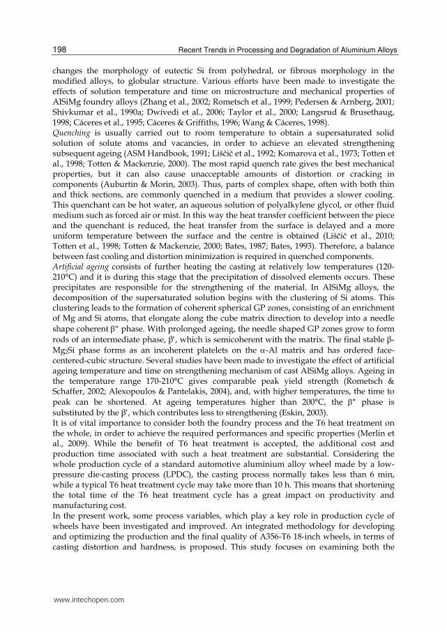
An approach for optimizing wheel production has been applied on A356-T6 18-inch wheels, which are 5-spoke wheels in the T6 temper, with a diameter of 457 mm and a rim width of 203 mm. Fig. 1 shows a sketch of the analysed wheel, which is generally cast by LPDC. The casting has a weight of about 18 kg.
Fig. 1. Sketch of the low-pressure die-cast wheel analysed; the ingate is located in the hub region
2.1 Alloy and casting parameters The cast wheels were produced with an AlSi7Mg alloy (EN AC-42100, equivalent to the US designation A356), whose composition is indicated in Table 1. The material was melted in a furnace set up at 730 ± 5°C. The melt was degassed with a rotary impeller by using nitrogen and modified with Sr-containing master alloy. AlTi5B1 rod type grain refiner was also added to the molten metal. The hydrogen level was evaluated before casting through a Reduced Pressure Test (RPT).
Alloy Al Si Fe Cu Mn Mg Zn Ti Sr
A356 bal. 7.20 0.135 0.009 0.010 0.265 0.004 0.126 0.0279
Table 1. Chemical composition of A356 alloy used in the present work (wt.%)
The die cavity is geometrically complex and is comprised of four sections: a bottom die, two side die sections, and a top die. These die sections are made by an AISI H13 tool steel. The temperature in the die, measured with thermocouples, was in the range of 450-520 ± 10°C. The casting process is cyclic and begins with the pressurization of the furnace, which contains a reservoir of molten aluminium. The excess pressure in the holding furnace forces the molten aluminium to fill the die cavity in 60 ± 4 s with a final pressure of 0.4 ± 0.015 bar. An overpressure of 1.2 ± 0.03 bar, reached after 10 ± 2 s from the end of the filling, was then applied for 210 ± 5 s. During solidification, cooling rates are controlled by forcing air (2–3 bar) through internal channels in the top and bottom dies, at various times during casting
www.intechopen.com
Recent Trends in Processing and Degradation of Aluminium Alloys
200
cycle. On the side dies, cooling can be ensured by air jets, aimed at various sections of the exterior face. After the complete solidification, the side dies open and the top die is raised vertically. The wheel remains fixed to the top die prior to be ejected onto a transfer tray rolled under the top die. The die is then closed and the cycle begins again. Typical cycle times are 5–6 min. The wheel was then automatically picked up by a robot and cooled. To obtain a set of different cooling rates, water in the temperature range of 30-90°C was adopted. Slow cooling rate in air was also used.
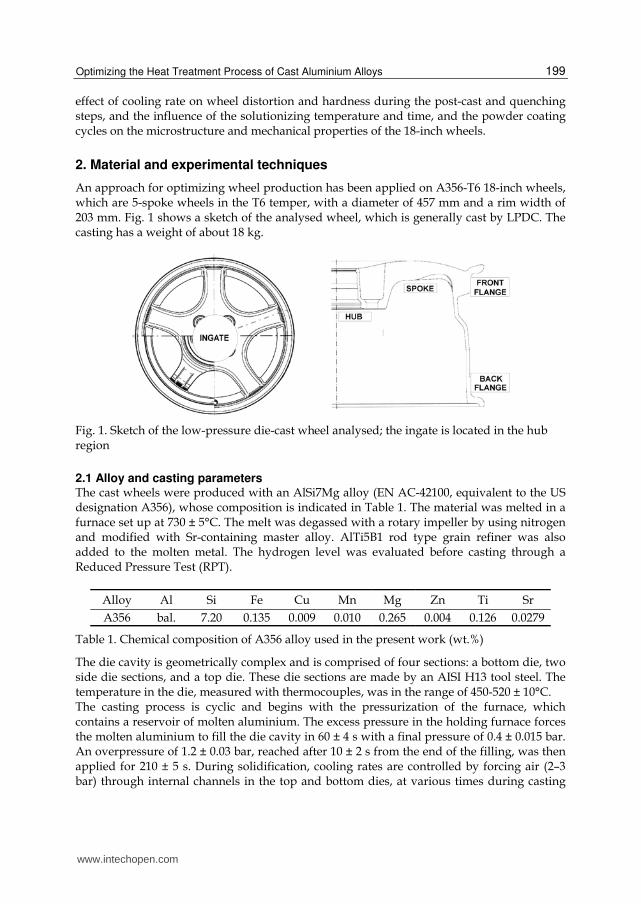
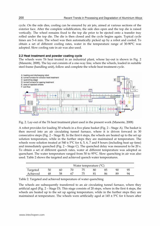
2.2 Heat treatment and powder coating cycle The wheels were T6 heat treated in an industrial plant, whose lay-out is shown in Fig. 2 (Manente, 2008). The lay-out consists of a one-way line, where the wheels, loaded in suitable steel frame (handling unit), follow and complete the whole heat treatment cycle.
Fig. 2. Lay-out of the T6 heat treatment plant used in the present work (Manente, 2008)
A robot provides for loading 30 wheels in a five plane basket (Fig. 2 – Stage A). The basket is then moved into an air circulating tunnel furnace, where it is driven forward in 30 consecutive steps (Fig. 2 – Stage B). In the first 6 steps, the wheels are heated up to the set up solution temperature, while in the further steps they are maintained at temperature. The wheels were solution treated at 540 ± 5°C for 4, 5, 6, 7 and 8 hours (including heat up time) and immediately quenched (Fig. 2 – Stage C). The quenched delay was measured to be 20 s. To obtain a set of different quench rates, water at different temperature was adopted as quenchant. The water temperature ranged from 50 to 95°C. Slow quenching in air was also used. Table 2 shows the targeted and achieved quench water temperatures.
Water temperature (°C)
Targeted 50 60 70 75 80 85 90 95 Achieved 48 58 67 75 81 86 89 94
Table 2. Targeted and achieved temperature of water quenching
The wheels are subsequently transferred to an air circulating tunnel furnace, where they artificial aged (Fig. 2 – Stage D). This stage consists of 20 steps, where in the first 4 steps, the wheels are heated up to the set up ageing temperature, while in the further steps they are maintained at temperature. The wheels were artificially aged at 145 ± 5°C for 4 hours after
www.intechopen.com
Optimizing the Heat Treatment Process of Cast Aluminium Alloys
201
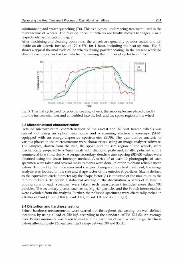
solutionizing and water quenching (T6). This is a typical underageing treatment used in the manufacture of wheels. The rejected or sound wheels are finally moved to Stages E or F respectively, as indicated in Fig. 2. After machining and cleaning operations, the wheels are generally powder coated and left inside an air electric furnace at 170 ± 5°C for 1 hour, including the heat-up time. Fig. 3. shows a typical thermal cycle of the wheels during powder coating. In the present work the effect of coating cycles has been studied by varying the number of cycles from 1 to 3.
Fig. 3. Thermal cycle used for powder coating wheels; thermocouples are placed directly into the furnace chamber and embedded into the hub and the spoke region of the wheel
2.3 Microstructural characterization Detailed microstructural characterisation of the as-cast and T6 heat treated wheels was carried out using an optical microscope and a scanning electron microscopy (SEM) equipped with an energy-dispersive spectrometer (EDS). The quantitative analysis of various phases in the microstructure were characterised using an image analyser software. The samples, drawn from the hub, the spoke and the rim region of the wheels, were mechanically prepared to a 3-µm finish with diamond paste and, finally, polished with a commercial fine silica slurry. Average secondary dendrite arm spacing (SDAS) values were obtained using the linear intercept method. A series of at least 10 photographs of each specimen were taken and several measurements were done, in order to obtain reliable mean values. To quantify the microstructural changes during solution heat treatment, the image analysis was focused on the size and shape factor of the eutectic Si particles. Size is defined
as the equivalent circle diameter (d); the shape factor (α) is the ratio of the maximum to the minimum Ferets. To obtain a statistical average of the distribution, a series of at least 15 photographs of each specimen were taken; each measurement included more than 700 particles. The secondary phases, such as the Mg-rich particles and the Fe-rich intermetallics, were excluded from the analysis. Further, the polished specimens were chemically etched in a Keller etchant (7.5 mL HNO3, 5 mL HCl, 2.5 mL HF and 35 mL H2O).
2.4 Distortion and hardness testing Brinell hardness measurements were carried out throughout the casting, on well defined locations, by using a load of 250 kgf, according to the standard ASTM E92-82. An average over 15 measurements was taken to evaluate the hardness of each wheel. Target hardness values after complete T6 heat treatment range between 90 and 95 HB.
www.intechopen.com
Recent Trends in Processing and Degradation of Aluminium Alloys
202
The amount of distortions of the wheels was carried out after post-cast cooling (ε) and after quenching (εt), by using a circular gauge, which allows to calculate the maximum variation of the diameter of the wheel along the rim. Generally, the maximum accepted distortion of a wheel is 1.5 mm, while wheels with higher distortions are normally rejected. This is a typical standard used for wheel manufacturing (Manente, 2008).
3. Results and discussion
The methodology to analyse and optimize the quality of A356-T6 18-inch wheels, in terms of casting distortion and hardness, and to optimise the whole process manufacturing is based on different steps: - analysis of as-cast wheels; - analysis of solution heat treated wheels; - analysis of quenched wheels; - analysis of powder coated wheels.
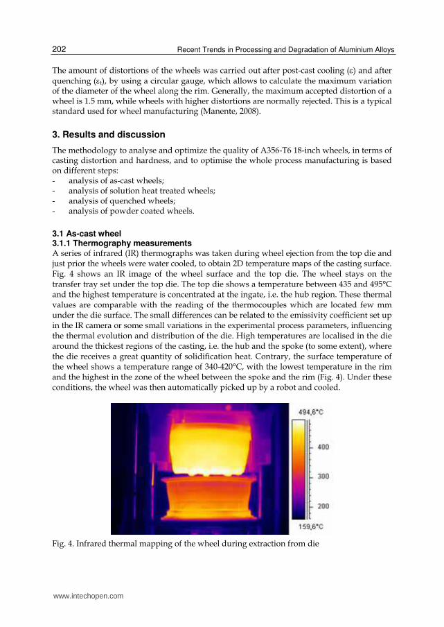
3.1 As-cast wheel 3.1.1 Thermography measurements A series of infrared (IR) thermographs was taken during wheel ejection from the top die and just prior the wheels were water cooled, to obtain 2D temperature maps of the casting surface. Fig. 4 shows an IR image of the wheel surface and the top die. The wheel stays on the transfer tray set under the top die. The top die shows a temperature between 435 and 495°C and the highest temperature is concentrated at the ingate, i.e. the hub region. These thermal values are comparable with the reading of the thermocouples which are located few mm under the die surface. The small differences can be related to the emissivity coefficient set up in the IR camera or some small variations in the experimental process parameters, influencing the thermal evolution and distribution of the die. High temperatures are localised in the die around the thickest regions of the casting, i.e. the hub and the spoke (to some extent), where the die receives a great quantity of solidification heat. Contrary, the surface temperature of the wheel shows a temperature range of 340-420°C, with the lowest temperature in the rim and the highest in the zone of the wheel between the spoke and the rim (Fig. 4). Under these conditions, the wheel was then automatically picked up by a robot and cooled.
Fig. 4. Infrared thermal mapping of the wheel during extraction from die
www.intechopen.com
Optimizing the Heat Treatment Process of Cast Aluminium Alloys
203
3.1.2 Microstructural observations of as-cast wheels
The microstructure of the modified A356 alloy consists of a primary phase, α-Al solid
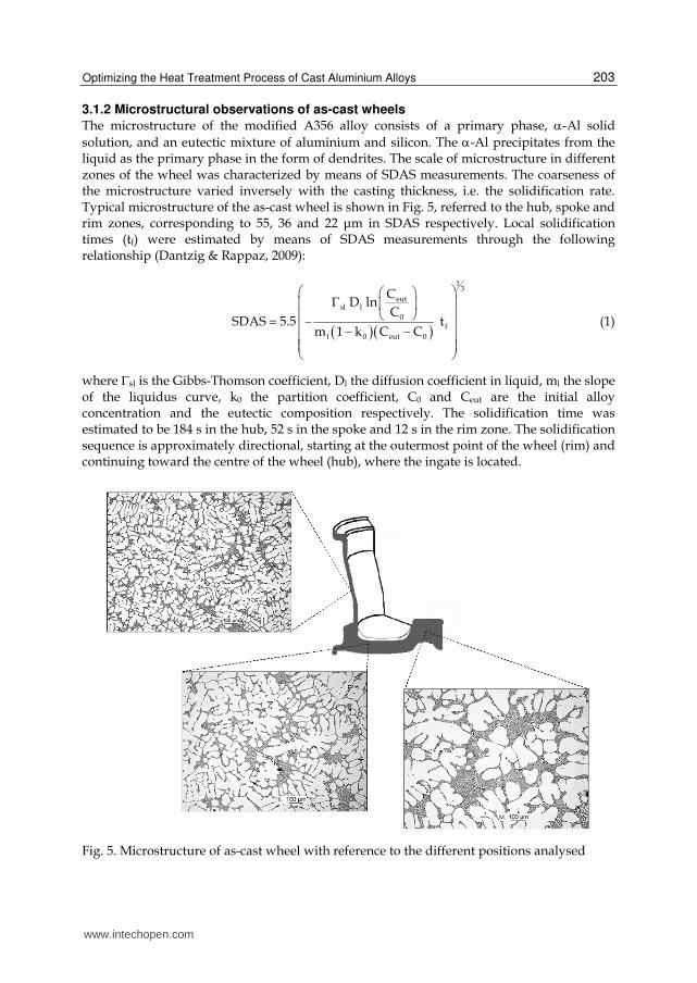
solution, and an eutectic mixture of aluminium and silicon. The α-Al precipitates from the liquid as the primary phase in the form of dendrites. The scale of microstructure in different zones of the wheel was characterized by means of SDAS measurements. The coarseness of the microstructure varied inversely with the casting thickness, i.e. the solidification rate. Typical microstructure of the as-cast wheel is shown in Fig. 5, referred to the hub, spoke and rim zones, corresponding to 55, 36 and 22 μm in SDAS respectively. Local solidification times (tf) were estimated by means of SDAS measurements through the following relationship (Dantzig & Rappaz, 2009):
( )( )1
3
eutsl l
0f
l 0 eut 0
CD ln
CSDAS 5.5 t
m 1 k C C
⎛ ⎞⎛ ⎞Γ ⎜ ⎟⎜ ⎟⎝ ⎠⎜ ⎟= − ⎜ ⎟− −⎜ ⎟⎜ ⎟⎝ ⎠ (1)
where Γsl is the Gibbs-Thomson coefficient, Dl the diffusion coefficient in liquid, ml the slope of the liquidus curve, k0 the partition coefficient, C0 and Ceut are the initial alloy concentration and the eutectic composition respectively. The solidification time was estimated to be 184 s in the hub, 52 s in the spoke and 12 s in the rim zone. The solidification sequence is approximately directional, starting at the outermost point of the wheel (rim) and continuing toward the centre of the wheel (hub), where the ingate is located.
Fig. 5. Microstructure of as-cast wheel with reference to the different positions analysed
www.intechopen.com
Recent Trends in Processing and Degradation of Aluminium Alloys
204
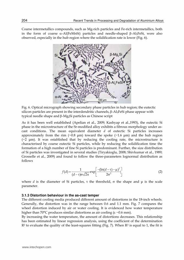
Coarse intermetallics compounds, such as Mg-rich particles and Fe-rich intermetallics, both
in the form of coarse α-Al(FeMnSi) particles and needle-shaped β-Al5FeSi, were also observed, especially in the hub region where the solidification rate is lower (Fig. 6).
Fig. 6. Optical micrograph showing secondary phase particles in hub region; the eutectic silicon particles are present in the interdendritic channels, β-Al5FeSi phase appear with typical needle shape and β-Mg2Si particles as Chinese script
As it has been well established (Apelian et al., 2009; Kashyap et al.,1993), the eutectic Si phase in the microstructure of the Sr-modified alloy exhibits a fibrous morphology under as-cast conditions. The mean equivalent diameter d of eutectic Si particles increases approximately from the rim (~0.8 μm) toward the spoke (~1.6 μm) and the hub region (~2 μm). It was established that by reducing the cooling rate, the microstructure is characterised by coarse eutectic Si particles, while by reducing the solidification time the formation of a high number of fine Si particles is predominant. Further, the size distribution of Si particles was investigated in several studies (Tiryakioglu, 2008; Shivkumar et al., 1989; Grosselle et al., 2009) and found to follow the three-parameters lognormal distribution as follows
2
2
1 (ln( ) )( ) exp
2( ) 2
⎡ ⎤− − τ − μ= ⎢ ⎥σ− τ σ π ⎣ ⎦d
f dd
(2)
where d is the diameter of Si particles, τ the threshold, σ the shape and μ is the scale parameter.
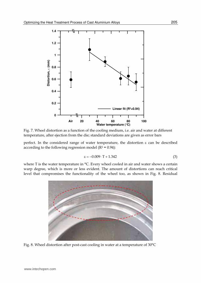
3.1.3 Distortion behaviour in the as-cast temper The different cooling media produced different amount of distortions in the 18-inch wheels. Generally, the distortion was in the range between 0.6 and 1.1 mm. Fig. 7 compares the wheel distortion induced by air or water cooling. It is evidenced how water temperature
higher than 70°C produces similar distortions as air cooling (ε ~0.6 mm). By increasing the water temperature, the amount of distortions decreases. This relationship has been estimated by linear regression analysis, using the coefficient of the determination R2 to evaluate the quality of the least-squares fitting (Fig. 7). When R2 is equal to 1, the fit is
www.intechopen.com
Optimizing the Heat Treatment Process of Cast Aluminium Alloys
205
20 40 60 80 100Water temperature (°C)
0
0.2
0.4
0.6
0.8
1
1.2
1.4
Dis
tort
ion
, ε (m
m)
Air
Linear fit (R2=0.94)
Fig. 7. Wheel distortion as a function of the cooling medium, i.e. air and water at different
temperature, after ejection from the die; standard deviations are given as error bars
perfect. In the considered range of water temperature, the distortion ε can be described
according to the following regression model (R2 = 0.94):
0.009 T 1.342ε = − ⋅ + (3)
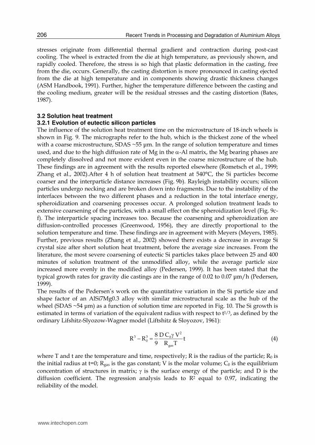
where T is the water temperature in °C. Every wheel cooled in air and water shows a certain
warp degree, which is more or less evident. The amount of distortions can reach critical
level that compromises the functionality of the wheel too, as shown in Fig. 8. Residual
Fig. 8. Wheel distortion after post-cast cooling in water at a temperature of 30°C
www.intechopen.com
Recent Trends in Processing and Degradation of Aluminium Alloys
206
stresses originate from differential thermal gradient and contraction during post-cast cooling. The wheel is extracted from the die at high temperature, as previously shown, and rapidly cooled. Therefore, the stress is so high that plastic deformation in the casting, free from the die, occurs. Generally, the casting distortion is more pronounced in casting ejected from the die at high temperature and in components showing drastic thickness changes (ASM Handbook, 1991). Further, higher the temperature difference between the casting and the cooling medium, greater will be the residual stresses and the casting distortion (Bates, 1987).
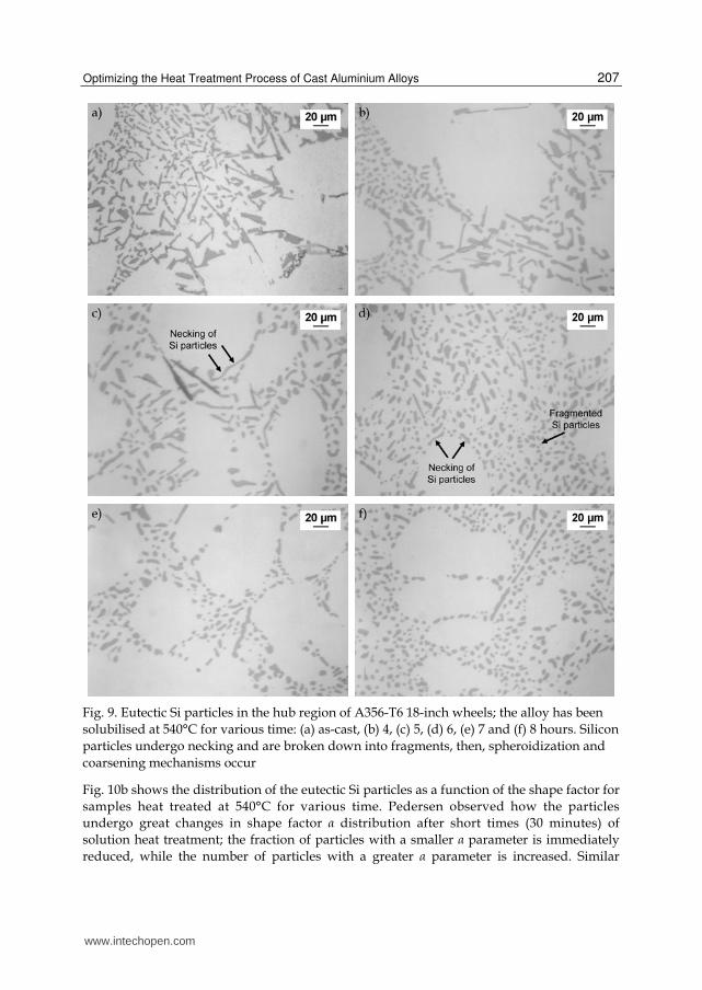
3.2 Solution heat treatment 3.2.1 Evolution of eutectic silicon particles The influence of the solution heat treatment time on the microstructure of 18-inch wheels is shown in Fig. 9. The micrographs refer to the hub, which is the thickest zone of the wheel with a coarse microstructure, SDAS ~55 μm. In the range of solution temperature and times
used, and due to the high diffusion rate of Mg in the α-Al matrix, the Mg bearing phases are completely dissolved and not more evident even in the coarse microstructure of the hub. These findings are in agreement with the results reported elsewhere (Rometsch et al., 1999; Zhang et al., 2002).After 4 h of solution heat treatment at 540°C, the Si particles become coarser and the interparticle distance increases (Fig. 9b). Rayleigh instability occurs; silicon particles undergo necking and are broken down into fragments. Due to the instability of the interfaces between the two different phases and a reduction in the total interface energy, spheroidization and coarsening processes occur. A prolonged solution treatment leads to extensive coarsening of the particles, with a small effect on the spheroidization level (Fig. 9c-f). The interparticle spacing increases too. Because the coarsening and spheroidization are diffusion-controlled processes (Greenwood, 1956), they are directly proportional to the solution temperature and time. These findings are in agreement with Meyers (Meyers, 1985). Further, previous results (Zhang et al., 2002) showed there exists a decrease in average Si crystal size after short solution heat treatment, before the average size increases. From the literature, the most severe coarsening of eutectic Si particles takes place between 25 and 400 minutes of solution treatment of the unmodified alloy, while the average particle size increased more evenly in the modified alloy (Pedersen, 1999). It has been stated that the typical growth rates for gravity die castings are in the range of 0.02 to 0.07 μm/h (Pedersen, 1999). The results of the Pedersen’s work on the quantitative variation in the Si particle size and shape factor of an AlSi7Mg0.3 alloy with similar microstructural scale as the hub of the wheel (SDAS ~54 μm) as a function of solution time are reported in Fig. 10. The Si growth is estimated in terms of variation of the equivalent radius with respect to t1/3, as defined by the ordinary Lifshitz-Slyozow-Wagner model (Liftshitz & Sloyozov, 1961):
2
3 3 00
gas
8 D C VR R t
9 R T
γ − = (4)
where T and t are the temperature and time, respectively; R is the radius of the particle; R0 is the initial radius at t=0; Rgas is the gas constant; V is the molar volume; C0 is the equilibrium
concentration of structures in matrix; γ is the surface energy of the particle; and D is the diffusion coefficient. The regression analysis leads to R2 equal to 0.97, indicating the reliability of the model.
www.intechopen.com
Optimizing the Heat Treatment Process of Cast Aluminium Alloys
207
Fig. 9. Eutectic Si particles in the hub region of A356-T6 18-inch wheels; the alloy has been
solubilised at 540°C for various time: (a) as-cast, (b) 4, (c) 5, (d) 6, (e) 7 and (f) 8 hours. Silicon
particles undergo necking and are broken down into fragments, then, spheroidization and
coarsening mechanisms occur
Fig. 10b shows the distribution of the eutectic Si particles as a function of the shape factor for
samples heat treated at 540°C for various time. Pedersen observed how the particles
undergo great changes in shape factor α distribution after short times (30 minutes) of
solution heat treatment; the fraction of particles with a smaller α parameter is immediately
reduced, while the number of particles with a greater α parameter is increased. Similar
www.intechopen.com

Recent Trends in Processing and Degradation of Aluminium Alloys
208
0 2 4 6 8Time of the solution heat treatment, t 1/3 (min)
0
0.4
0.8
1.2
1.6
2
Eq
uiv
ale
nt
rad
ius, R
(µ
m)
Linear fit (R2=0.97)
0 0.1 0.2 0.3 0.4 0.5 0.6 0.7 0.8 0.9 1
Shape factor, α0
5
10
15
20
25
30
Fre
qu
en
cy (
%)
As cast
30 min
60 min
120 min
240 min
480 min
(a) (b)
Fig. 10. (a) Linear regression analysis of eutectic Si equivalent radius with t1/3; the point zero
in the time axis represents the as-cast condition; (b) frequency distribution of the shape
factor α after solution treatment at 540°C for different times (Pedersen, 1999)
20 30 40 50 60SDAS (µm)
0.4
0.8
1.2
1.6
2
2.4
2.8
Eq
uiv
ale
nt
dia
me
ter,
d (
µm
)
As-cast
Solution treatment 540°C for 6h
Hub
Spoke
Rim
Fig. 11. Average diameter d of the eutectic Si particles as a function of SDAS; data refer to
the different positions of the as-cast and solution heat treated wheels
changes in particle distribution are not observed by increasing the solution times within 4 hours, even if the distribution curves flatten with solution time and their peaks move to the
www.intechopen.com
Optimizing the Heat Treatment Process of Cast Aluminium Alloys
209
right toward higher α values. Only after 8 hours solution time, the shape factor distribution
moves to higher α values. The eutectic Si particles in AlSi7Mg gravity-cast alloys crack
progressively with increasing applied plastic deformation, and the crack is favourable for
the larger and longer particles, even if the progression of particle cracking is more gradual
in a finer microstructure (Cáceres & Griffiths, 1996). In addition, it was observed that the
population of cracked particles is distributed according to the α·d parameter and is
characterized by its average α·d value.
Since solidification rate has a dramatic effect on the size and morphology of eutectic Si
particles, it is important to be aware of the influence of the solidification rate on the required
minimum solution time for realizing the required coarsening and spheroidization. It was
reported (Shivkumar et al., 1990c) that 3-6 h at 540°C is the optimal time for a Sr-modified
sand-cast A356 alloy; while 30 min at 540°C is needed for a low-pressure die-cast
Sr-modified A356 alloy with SDAS of 25 μm (Zhang et al., 2002). Fig. 11 shows the effect of a
solution treatment at 540 °C for 6 h on the Si particle size in the different positions of the
wheels ,where different microstructural scales were observed. The coarsening mechanism is
faster in the rim and spoke region, where SDAS is about 22 and 36 μm respectively. While
the coarse microstructure of the hub presents slower coarsening of Si particles, as indicated
by the values of equivalent diameter in the as-cast and solution heat treated temper.
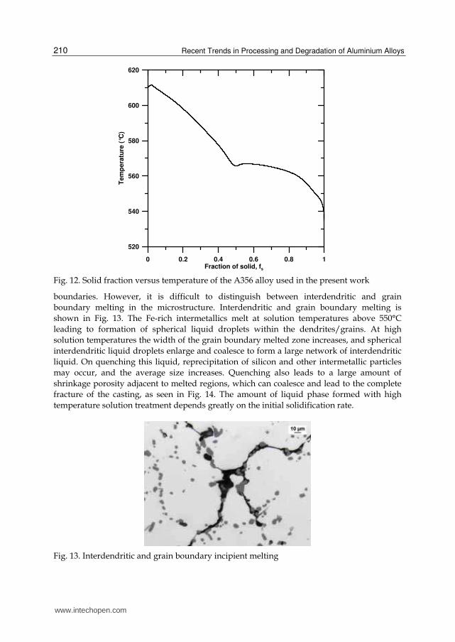
3.2.2 Partial melting The increase of solution temperatures for the heat treatment of the wheels would be desirable since it increases the diffusion rate of Si atoms in the Al matrix, leading to rapid fragmentation and coarsening mechanism of eutectic Si particles, and, therefore, to shorten the total time of the T6 heat treatment cycle. It was demonstrated that for a given short solution treatment time of 9.5 minutes, increasing the temperature from 540 to 550°C the number fraction of Si particles with a diameter of greater than 1 μm increases by more than 10%. Similar changes in the distribution of the shape factor for Si particles are observed by increasing the solution temperature, that is the number fraction of the particles with a shape factor of greater than 0.5 increases by approximately 10% (Zhang et al., 2002). Earlier works (Shivkumar et al., 1990b) showed that extremely high coarsening occurred at temperatures greater than 540°C for A356.2 alloys. However, the major problem associated with higher heat treatment temperatures remains the liquid phase formation, which increases with temperature. In the present work, the possibility to heat the wheels at higher solution temperature was evaluated. A Fourier thermal analysis was carried out to determine the evolution of the solid fraction during solidification of the A356 alloy used for wheel production. A detailed description of the equipment, the casting procedure, and the process parameters is given elsewhere (Piasentini et al., 2005). The relationship between fraction of solid (fs) and temperature of solidifying A356 alloy is shown in Fig. 12 for a cooling rate of 1°C/s. With increasing solution temperature above 540°C (final solidification point), the amount of liquid phase (100 fs) increases slowly at first and then rapidly near the Al-Si eutectic reaction of ~560°C, at which point the fraction of liquid (100-fs) is about 15%. At relatively lower solution temperatures, melting starts at grain boundaries and interdendritic regions. In alloys with a dendritic structure, local melting starts generally at interdendritic channels, since these often contain high concentrations of alloying elements/impurities. At higher solution temperatures, local melting may also start at grain
www.intechopen.com
Recent Trends in Processing and Degradation of Aluminium Alloys
210
0 0.2 0.4 0.6 0.8 1Fraction of solid, fs
520
540
560
580
600
620
Tem
pera
ture
(°C
)
Fig. 12. Solid fraction versus temperature of the A356 alloy used in the present work
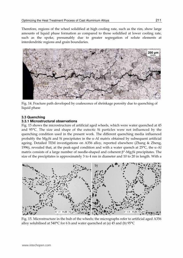
boundaries. However, it is difficult to distinguish between interdendritic and grain
boundary melting in the microstructure. Interdendritic and grain boundary melting is
shown in Fig. 13. The Fe-rich intermetallics melt at solution temperatures above 550°C
leading to formation of spherical liquid droplets within the dendrites/grains. At high
solution temperatures the width of the grain boundary melted zone increases, and spherical
interdendritic liquid droplets enlarge and coalesce to form a large network of interdendritic
liquid. On quenching this liquid, reprecipitation of silicon and other intermetallic particles
may occur, and the average size increases. Quenching also leads to a large amount of
shrinkage porosity adjacent to melted regions, which can coalesce and lead to the complete
fracture of the casting, as seen in Fig. 14. The amount of liquid phase formed with high
temperature solution treatment depends greatly on the initial solidification rate.
Fig. 13. Interdendritic and grain boundary incipient melting
www.intechopen.com
Optimizing the Heat Treatment Process of Cast Aluminium Alloys
211
Therefore, regions of the wheel solidified at high cooling rate, such as the rim, show large
amounts of liquid phase formation as compared to those solidified at lower cooling rate,
such as the spoke, presumably due to greater segregation of solute elements at
interdendritic regions and grain boundaries.
Fig. 14. Fracture path developed by coalescence of shrinkage porosity due to quenching of
liquid phase
3.3 Quenching 3.3.1 Microstructural observations Fig. 15 shows the microstructure of artificial aged wheels, which were water quenched at 45
and 95°C. The size and shape of the eutectic Si particles were not influenced by the
quenching condition used in the present work. The different quenching media influenced
probably the Mg2Si and Si precipitates in the α-Al matrix obtained by subsequent artificial
ageing. Detailed TEM investigations on A356 alloy, reported elsewhere (Zhang & Zheng,
1996), revealed that, at the peak-aged condition and with a water quench at 25°C, the α-Al
matrix consists of a large number of needle-shaped and coherent β″-Mg2Si precipitates. The
size of the precipitates is approximately 3 to 4 nm in diameter and 10 to 20 in length. With a
Fig. 15. Microstructure in the hub of the wheels; the micrographs refer to artificial aged A356
alloy solubilised at 540°C for 6 h and water quenched at (a) 45 and (b) 95°C
www.intechopen.com

Recent Trends in Processing and Degradation of Aluminium Alloys
212
water quench at 60°C, Zhang and Zheng observed how the density of the precipitates decreases and the size of the precipitates increases slightly; at the same time a significant number of fine Si precipitates resulting from precipitation of excess Si could be observed in
the α-Al matrix. With a slow quenching in air, very different precipitation features are normally evidenced.
By air quenching, the material remains at high temperatures for a longer period, which
enhances the diffusion of silicon and magnesium. Besides a high density of fine β″-Mg2Si
precipitates, the α-Al matrix also contained a large number of areas with coarse rods
β′-Mg2Si grouped parallel to each other (Zhang & Zheng, 1996). While the first precipitates
have an average size approximately 2 to 3 nm in diameter and around 40 nm in length, the
latter show an average size ~15 nm in diameter and 300 nm in length.
Fig. 16. Silicon precipitates within dendrites in A356-T6 wheels that have been slowly
quenched in air; arrows indicate the Si particles in the α-Al matrix, as revealed by EDS spectra. Precipitate-free zone (PFZ) is indicated near the eutectic regions
Due to the low Mg content in the present alloy, a high excess Si concentration is present in
the α-Al matrix. Assuming the stoichiometric formation of β′-Mg2Si, this alloy concentration
should form 0.3 wt.% Mg2Si and an excess of 1 wt.% Si in the alloy, which precipitates as
coarse particles within the α-Al matrix (Fig. 16), as revealed by EDS spectra. Further, a
clearly visible precipitate-free zone (PFZ) can be seen near the eutectic regions, illustrating
that Si has diffused towards existing crystals; such region is marked in Fig. 16.
3.3.2 Distortion behaviour of quenched wheels
The overall distortion εt on 18-inch wheels was measured after quenching in water at
different temperature. The different quenching rates obtained using water at different
www.intechopen.com
Optimizing the Heat Treatment Process of Cast Aluminium Alloys
213
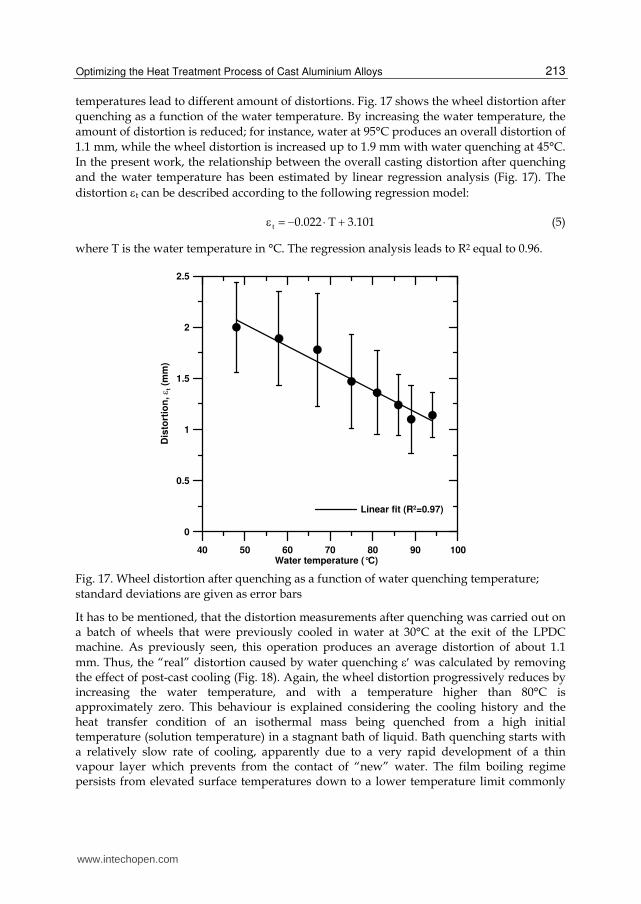
temperatures lead to different amount of distortions. Fig. 17 shows the wheel distortion after
quenching as a function of the water temperature. By increasing the water temperature, the
amount of distortion is reduced; for instance, water at 95°C produces an overall distortion of
1.1 mm, while the wheel distortion is increased up to 1.9 mm with water quenching at 45°C.
In the present work, the relationship between the overall casting distortion after quenching
and the water temperature has been estimated by linear regression analysis (Fig. 17). The
distortion εt can be described according to the following regression model:
t 0.022 T 3.101ε = − ⋅ + (5)
where T is the water temperature in °C. The regression analysis leads to R2 equal to 0.96.
40 50 60 70 80 90 100Water temperature (°C)
0
0.5
1
1.5
2
2.5
Dis
tort
ion
, ε t (m
m)
Linear fit (R2=0.97)
Fig. 17. Wheel distortion after quenching as a function of water quenching temperature;
standard deviations are given as error bars
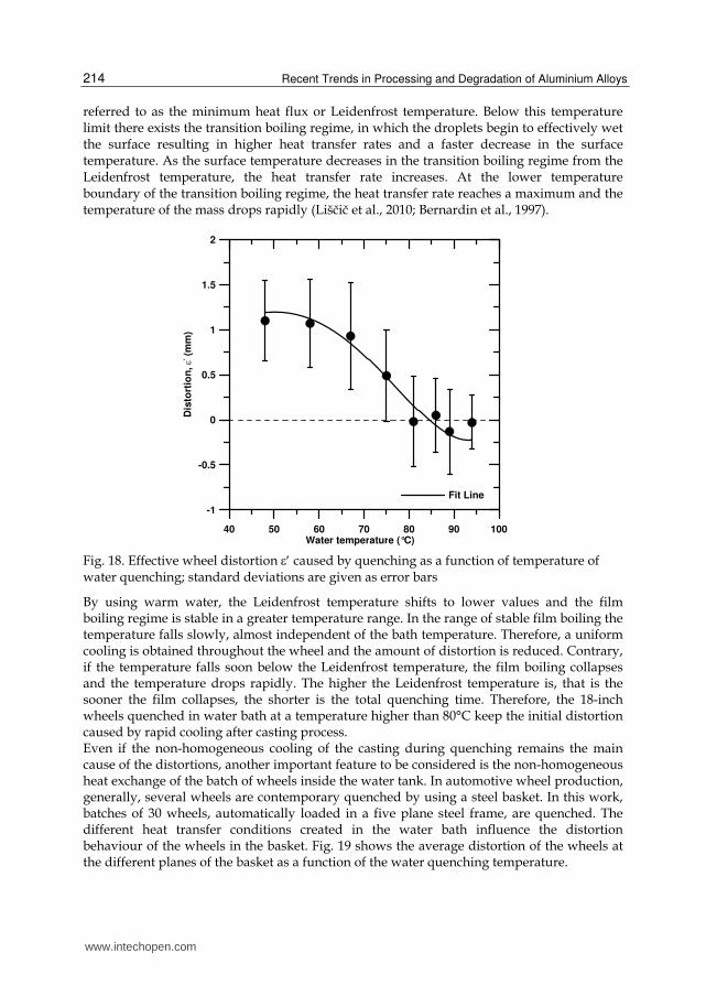
It has to be mentioned, that the distortion measurements after quenching was carried out on a batch of wheels that were previously cooled in water at 30°C at the exit of the LPDC machine. As previously seen, this operation produces an average distortion of about 1.1
mm. Thus, the “real” distortion caused by water quenching ε′ was calculated by removing the effect of post-cast cooling (Fig. 18). Again, the wheel distortion progressively reduces by increasing the water temperature, and with a temperature higher than 80°C is approximately zero. This behaviour is explained considering the cooling history and the heat transfer condition of an isothermal mass being quenched from a high initial temperature (solution temperature) in a stagnant bath of liquid. Bath quenching starts with a relatively slow rate of cooling, apparently due to a very rapid development of a thin vapour layer which prevents from the contact of “new” water. The film boiling regime persists from elevated surface temperatures down to a lower temperature limit commonly
www.intechopen.com
Recent Trends in Processing and Degradation of Aluminium Alloys
214
referred to as the minimum heat flux or Leidenfrost temperature. Below this temperature limit there exists the transition boiling regime, in which the droplets begin to effectively wet the surface resulting in higher heat transfer rates and a faster decrease in the surface temperature. As the surface temperature decreases in the transition boiling regime from the Leidenfrost temperature, the heat transfer rate increases. At the lower temperature boundary of the transition boiling regime, the heat transfer rate reaches a maximum and the temperature of the mass drops rapidly (Liščič et al., 2010; Bernardin et al., 1997).
40 50 60 70 80 90 100Water temperature (°C)
-1
-0.5
0
0.5
1
1.5
2
Dis
tort
ion
, ε' (
mm
)
Fit Line
Fig. 18. Effective wheel distortion ε′ caused by quenching as a function of temperature of water quenching; standard deviations are given as error bars
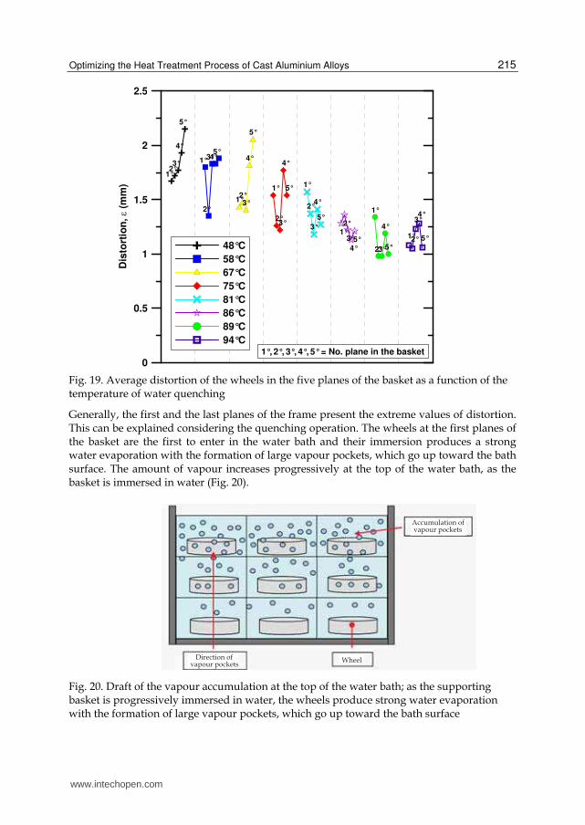
By using warm water, the Leidenfrost temperature shifts to lower values and the film boiling regime is stable in a greater temperature range. In the range of stable film boiling the temperature falls slowly, almost independent of the bath temperature. Therefore, a uniform cooling is obtained throughout the wheel and the amount of distortion is reduced. Contrary, if the temperature falls soon below the Leidenfrost temperature, the film boiling collapses and the temperature drops rapidly. The higher the Leidenfrost temperature is, that is the sooner the film collapses, the shorter is the total quenching time. Therefore, the 18-inch wheels quenched in water bath at a temperature higher than 80°C keep the initial distortion caused by rapid cooling after casting process. Even if the non-homogeneous cooling of the casting during quenching remains the main cause of the distortions, another important feature to be considered is the non-homogeneous heat exchange of the batch of wheels inside the water tank. In automotive wheel production, generally, several wheels are contemporary quenched by using a steel basket. In this work, batches of 30 wheels, automatically loaded in a five plane steel frame, are quenched. The different heat transfer conditions created in the water bath influence the distortion behaviour of the wheels in the basket. Fig. 19 shows the average distortion of the wheels at the different planes of the basket as a function of the water quenching temperature.
www.intechopen.com
Optimizing the Heat Treatment Process of Cast Aluminium Alloys
215
0
0.5
1
1.5
2
2.5
Dis
tort
ion
, ε (m
m)
1°2°3°
4°
5°
1°
2°
3°4°5°
1°2°3°
4°
5°
1°
2°3°
4°
5° 1°
2°
3°
4°
5°
1°2°
3°
4°5°
1°
2°3°
4°
5°
1°2°
3°4°
5°48°C
58°C
67°C
75°C
81°C
86°C
89°C
94°C1°, 2°, 3°, 4°, 5° = No. plane in the basket
Fig. 19. Average distortion of the wheels in the five planes of the basket as a function of the temperature of water quenching
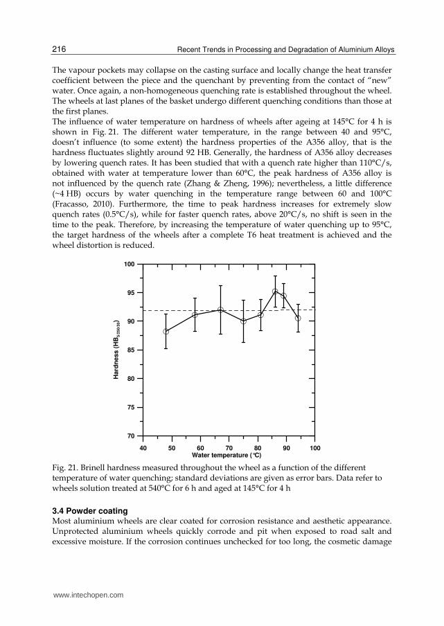
Generally, the first and the last planes of the frame present the extreme values of distortion. This can be explained considering the quenching operation. The wheels at the first planes of the basket are the first to enter in the water bath and their immersion produces a strong water evaporation with the formation of large vapour pockets, which go up toward the bath surface. The amount of vapour increases progressively at the top of the water bath, as the basket is immersed in water (Fig. 20).
Wheel
Accumulation of vapour pockets
Direction ofvapour pockets
Fig. 20. Draft of the vapour accumulation at the top of the water bath; as the supporting basket is progressively immersed in water, the wheels produce strong water evaporation with the formation of large vapour pockets, which go up toward the bath surface
www.intechopen.com
Recent Trends in Processing and Degradation of Aluminium Alloys
216
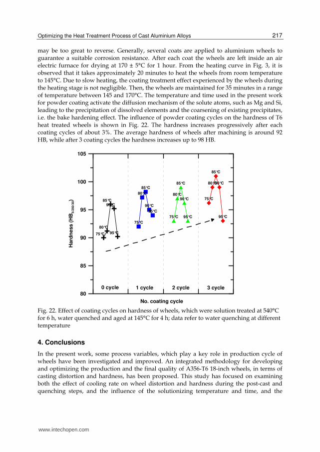
The vapour pockets may collapse on the casting surface and locally change the heat transfer coefficient between the piece and the quenchant by preventing from the contact of “new” water. Once again, a non-homogeneous quenching rate is established throughout the wheel. The wheels at last planes of the basket undergo different quenching conditions than those at the first planes. The influence of water temperature on hardness of wheels after ageing at 145°C for 4 h is shown in Fig. 21. The different water temperature, in the range between 40 and 95°C, doesn’t influence (to some extent) the hardness properties of the A356 alloy, that is the hardness fluctuates slightly around 92 HB. Generally, the hardness of A356 alloy decreases by lowering quench rates. It has been studied that with a quench rate higher than 110°C/s, obtained with water at temperature lower than 60°C, the peak hardness of A356 alloy is not influenced by the quench rate (Zhang & Zheng, 1996); nevertheless, a little difference (~4 HB) occurs by water quenching in the temperature range between 60 and 100°C (Fracasso, 2010). Furthermore, the time to peak hardness increases for extremely slow quench rates (0.5°C/s), while for faster quench rates, above 20°C/s, no shift is seen in the time to the peak. Therefore, by increasing the temperature of water quenching up to 95°C, the target hardness of the wheels after a complete T6 heat treatment is achieved and the wheel distortion is reduced.
40 50 60 70 80 90 100Water temperature (°C)
70
75
80
85
90
95
100
Hard
ness (
HB
5/2
50/3
0)
Fig. 21. Brinell hardness measured throughout the wheel as a function of the different temperature of water quenching; standard deviations are given as error bars. Data refer to wheels solution treated at 540°C for 6 h and aged at 145°C for 4 h
3.4 Powder coating Most aluminium wheels are clear coated for corrosion resistance and aesthetic appearance. Unprotected aluminium wheels quickly corrode and pit when exposed to road salt and excessive moisture. If the corrosion continues unchecked for too long, the cosmetic damage
www.intechopen.com
Optimizing the Heat Treatment Process of Cast Aluminium Alloys
217
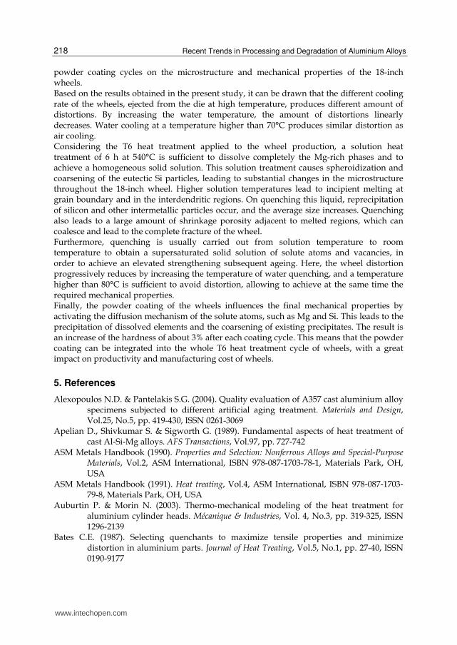
may be too great to reverse. Generally, several coats are applied to aluminium wheels to guarantee a suitable corrosion resistance. After each coat the wheels are left inside an air electric furnace for drying at 170 ± 5°C for 1 hour. From the heating curve in Fig. 3, it is observed that it takes approximately 20 minutes to heat the wheels from room temperature to 145°C. Due to slow heating, the coating treatment effect experienced by the wheels during the heating stage is not negligible. Then, the wheels are maintained for 35 minutes in a range of temperature between 145 and 170°C. The temperature and time used in the present work for powder coating activate the diffusion mechanism of the solute atoms, such as Mg and Si, leading to the precipitation of dissolved elements and the coarsening of existing precipitates, i.e. the bake hardening effect. The influence of powder coating cycles on the hardness of T6 heat treated wheels is shown in Fig. 22. The hardness increases progressively after each coating cycles of about 3%. The average hardness of wheels after machining is around 92 HB, while after 3 coating cycles the hardness increases up to 98 HB.
No. coating cycle
80
85
90
95
100
105
Hard
ne
ss
(H
B5
/250
/30)
75°C
80°C
85°C90°C
95°C
75°C
80°C
85°C
90°C
95°C
75°C
80°C
85°C
90°C
95°C
75°C
80°C
85°C
90°C
95°C
0 cycle 1 cycle 2 cycle 3 cycle
Fig. 22. Effect of coating cycles on hardness of wheels, which were solution treated at 540°C for 6 h, water quenched and aged at 145°C for 4 h; data refer to water quenching at different temperature
4. Conclusions
In the present work, some process variables, which play a key role in production cycle of wheels have been investigated and improved. An integrated methodology for developing and optimizing the production and the final quality of A356-T6 18-inch wheels, in terms of casting distortion and hardness, has been proposed. This study has focused on examining both the effect of cooling rate on wheel distortion and hardness during the post-cast and quenching steps, and the influence of the solutionizing temperature and time, and the
www.intechopen.com
Recent Trends in Processing and Degradation of Aluminium Alloys
218
powder coating cycles on the microstructure and mechanical properties of the 18-inch wheels. Based on the results obtained in the present study, it can be drawn that the different cooling rate of the wheels, ejected from the die at high temperature, produces different amount of distortions. By increasing the water temperature, the amount of distortions linearly decreases. Water cooling at a temperature higher than 70°C produces similar distortion as air cooling. Considering the T6 heat treatment applied to the wheel production, a solution heat treatment of 6 h at 540°C is sufficient to dissolve completely the Mg-rich phases and to achieve a homogeneous solid solution. This solution treatment causes spheroidization and coarsening of the eutectic Si particles, leading to substantial changes in the microstructure throughout the 18-inch wheel. Higher solution temperatures lead to incipient melting at grain boundary and in the interdendritic regions. On quenching this liquid, reprecipitation of silicon and other intermetallic particles occur, and the average size increases. Quenching also leads to a large amount of shrinkage porosity adjacent to melted regions, which can coalesce and lead to the complete fracture of the wheel. Furthermore, quenching is usually carried out from solution temperature to room temperature to obtain a supersaturated solid solution of solute atoms and vacancies, in order to achieve an elevated strengthening subsequent ageing. Here, the wheel distortion progressively reduces by increasing the temperature of water quenching, and a temperature higher than 80°C is sufficient to avoid distortion, allowing to achieve at the same time the required mechanical properties. Finally, the powder coating of the wheels influences the final mechanical properties by activating the diffusion mechanism of the solute atoms, such as Mg and Si. This leads to the precipitation of dissolved elements and the coarsening of existing precipitates. The result is an increase of the hardness of about 3% after each coating cycle. This means that the powder coating can be integrated into the whole T6 heat treatment cycle of wheels, with a great impact on productivity and manufacturing cost of wheels.
5. References
Alexopoulos N.D. & Pantelakis S.G. (2004). Quality evaluation of A357 cast aluminium alloy specimens subjected to different artificial aging treatment. Materials and Design, Vol.25, No.5, pp. 419-430, ISSN 0261-3069
Apelian D., Shivkumar S. & Sigworth G. (1989). Fundamental aspects of heat treatment of cast Al-Si-Mg alloys. AFS Transactions, Vol.97, pp. 727-742
ASM Metals Handbook (1990). Properties and Selection: Nonferrous Alloys and Special-Purpose Materials, Vol.2, ASM International, ISBN 978-087-1703-78-1, Materials Park, OH, USA
ASM Metals Handbook (1991). Heat treating, Vol.4, ASM International, ISBN 978-087-1703-79-8, Materials Park, OH, USA
Auburtin P. & Morin N. (2003). Thermo-mechanical modeling of the heat treatment for aluminium cylinder heads. Mécanique & Industries, Vol. 4, No.3, pp. 319-325, ISSN 1296-2139
Bates C.E. (1987). Selecting quenchants to maximize tensile properties and minimize distortion in aluminium parts. Journal of Heat Treating, Vol.5, No.1, pp. 27-40, ISSN 0190-9177
www.intechopen.com
Optimizing the Heat Treatment Process of Cast Aluminium Alloys
219
Bates C.E. (1994). Quench Optimization for Aluminum Alloys. AFS Transactions, Vol.101, pp. 1045-1054
Bernardin J.D., Stebbins C.J. and Mudawar I. (1997). Mapping of impact and heat transfer regimes of water drops impinging on a polished surface. International Journal of Heat and Mass Transfer , Vol.40, No.2, pp.247-267, ISSN 0017-9310
Cáceres C.H. & Griffiths J.R. (1996). Damage by the cracking of silicon particles in an Al-7Si-0.4Mg casting alloy. Acta materialia, Vol.44, No.1, pp. 25-33, ISSN 1359-6454
Cáceres C.H., Davidson C.J. & Griffiths J.R. (1995). Deformation and fracture behaviour of an Al-Si-Mg casting alloy. Materials Science and Engineering A, Vol.197, No.2, pp. 171-179, ISSN 0921-5093
Conserva M., Bonollo F. & Donzelli G. (2004). Alluminio, manuale degli impieghi, Edimet, ISBN 978-888-6259-27-9, Brescia, Italy
Dantzig J.A. & Rappaz M. (2009). Solidification, CRC Press, Taylor & Francis Group, ISBN 978-084-9382-38-3, Boca Raton, USA
Dwivedi D.K., Sharma R. & Kumar A. (2006). Influence of silicon content and heat treatment parameters on mechanical properties of cast Al-Si-Mg alloys. International Journal of Cast Metals Research, Vol.19, No.5, pp. 275-282, ISSN 1364-0461
Eskin D.G. (2003). Decomposition of supersaturated solid solutions in Al-Cu-Mg-Si alloys. Journal of Materials Science, Vol.38, No.2, pp. 279-290, ISSN 0022-2461
Fracasso F. (2010). Influence of quench rate on the hardness obtained after artificial ageing of an Al-Si-Mg alloy. Master Thesis, University of Padova, Padova, Italy
Greenwood G.W. (1956). The growth of dispersed precipitates in solutions. Acta Metallurgica, Vol.4, No.3, pp. 243-248
Grosselle F., Timelli G., Bonollo F., Tiziani A. & Della Corte E. (2009). Correlation between microstructure and mechanical properties of Al-Si cast alloys. Metallurgia Italiana, Vol.101, No.6, pp. 25-32, ISSN 0026-0843
Kashyap K.T., Murali S., Raman K.S. & Murthy K.S.S. (1993). Casting and heat-treatment variables of Al-7Si-Mg alloy. Materials Science and Technology, Vol.9, No.3, pp. 189-203, ISSN 0267-0836
Komarova M.F., Buynov N.N. & Kaganovich L.I. (1973). Influence of quenching rate and small alloying additions on the kinetics and morphology of precipitations in aluminium-silicon-magnesium alloys. Physics of Metals and Metallography, Vol.36 No.3, pp. 72-79, ISSN 0031-918X
Langsrud Y. & Brusethaug S. (1998). Age hardening response of AlSiMg foundry alloys, In: ICAA6 – Aluminum Alloys, Their Physical and Mechanical Properties, T. Sato, S. Kumai, T. Kobayashi and Y. Murakami, (Ed.), 733-738, The Japanese Institute of Light Metals, Japan
Liftshitz I.M. & Sloyozov V.V. (1961). The kinetics of precipitation from supersaturated solid solutions. Journal of Physics and Chemistry of Solids, Vol.19, No.1-2, pp. 35-50
Liščič B., Tensi H.M., Canale L.C.F. & Totten G.E. (2010). Theory and Technology of Quenching, CRC Press, Taylor & Francis Group, ISBN 978-084-9392-79-5, Boca Raton, USA
Manente A. (2008). La fonderia di alluminio nella pratica quotidiana, Edimet, ISBN 88-86259-35-1, Brescia, Italy
Merlin M., Timelli G., Bonollo F. & Garagnani G.L. (2009). Impact behaviour of A356 alloy for low-pressure die casting automotive wheels. Journal of Materials Processing Technology, Vol.209, No.2, pp. 1060-1073, ISSN 0924-0136
Meyers C.W. (1985). Solution heat treatment effects in A357 alloys. AFS Transactions, Vol.112, pp. 741-750
www.intechopen.com
Recent Trends in Processing and Degradation of Aluminium Alloys
220
Pedersen L. & Arnberg L. (2001). The effect of solution heat treatment and quenching rates on mechanical properties and microstructures in AlSiMg foundry alloys. Metallurgical and Materials Transactions A, Vol.32, No.3, pp. 525-532, ISSN 1073-5623
Pedersen L. (1999). Solution heat treatment of AlSiMg foundry alloys. Doctoral Thesis, Norwegian University of Science and Technology, ISBN 82-471-0409-1, Trondheim, Norway
Piasentini F., Bonollo F. & Tiziani A. (2005). Fourier thermal analysis applied to sodium eutectic modification of an AlSi7 alloy. Metallurgical Science and Technology, Vol.23, No.2, pp. 11-20
Rometsch P.A. & Schaffer G.B. (2002). An age hardening model for Al-7Si-Mg casting alloys. Materials Science and Engineering A, Vol.325, No.1-2, pp. 424-434, ISSN 0921-5093
Rometsch P.A., Arnberg L. & Zhang D.L. (1999). Modelling dissolution of Mg2Si and homogenisation in Al-Si-Mg casting alloys. International Journal of Cast Metals Research, Vol.12, No.1, pp. 1-8, ISSN 1364-0461
Shivkumar S., Keller C. & Apelian D. (1990a). Aging behavior in cast Al-Si-Mg alloys. AFS Transactions, Vol.98, pp. 905-911
Shivkumar S., Ricci Jr. S. & Apelian D. (1990b). "Influence of solution and simplified supersaturation treatment on tensile properties of A356 alloy. AFS Transactions, Vol.98, pp. 913-922
Shivkumar S., Ricci Jr. S., Steenhoff B., Apelian D. & Sigworth G. (1989). An experimental study to optimize the heat treatment of A356 alloy. AFS Transactions, Vol.97, pp. 791-810
Shivkumar S., Ricci S., Keller C. & D. Apelian (1990c). Effect of solution treatment parameters on tensile properties of cast aluminum alloys. Journal of Heat Treating, Vol.8, No.1, pp. 63-70, ISSN 0190-9177
Taylor J.A., StJohn D.H., Barresi J. & Couper M.J. (2000). Influence of Mg content on the microstructure and solid solution chemistry of Al-7%Si-Mg casting alloys during solution treatment. Materials Science Forum, Vol.331, pp. 277-282, ISSN 0255-5476
Tiryakioglu M. (2008). Si particle size and aspect ratio distributions in an Al-7%Si-0.6%Mg alloy during solution treatment. Materials Science and Engineering A, Vol.473, No.1-2, pp. 1-6, ISSN 0921-5093
Totten G.E. & Mackenzie D.S. (2000). Aluminum quenching technology: a review. Materials Science Forum, Vol.331, pp. 589-594, ISSN 0255-5476
Totten G.E., Webster G.M. & Bates C.E. (1998). Cooling curve and quench factor characterization of 2024 and 7075 aluminum bar stock quenched in type 1 polymer quenchants. Heat Transfer Research, Vol.29, No.1, pp. 163-175, ISSN 1064-2285
Valentini G. (2002). Application of die-castings in automotive industry: a review, Proceedings of HTDC 2002 International Conference High Tech Diecasting (Al and Mg alloys), pp. 237-250, ISBN 88-85298-43-5, Vicenza, Italy, February 22, 2002
Wang Q.G. & Cáceres C.H. (1998). Fracture mode in Al-Si-Mg casting alloys. Materials Science and Engineering A, Vol.241, No.1-2, pp. 72-82, ISSN 0921-5093
Zhang D.L. & Zheng L. (1996). Quench sensitivity of cast Al-7 wt pct Si-0.4 wt pct Mg Alloy, Metallurgical and Materials Transaction A, Vol.27, No.12, pp. 3983-3991, ISSN 1073-5623
Zhang D.L., Zheng L.H. & StJohn D.H. (2002). Effect of a short solution treatment time on microstructure and mechanical properties of modified Al-7wt.%Si-0.3wt.%Mg alloy. Journal of Light Metals, Vol.2, No.1, pp. 27-36, ISSN 1471-5317
www.intechopen.com
Recent Trends in Processing and Degradation of Aluminium AlloysEdited by Prof. Zaki Ahmad
ISBN 978-953-307-734-5Hard cover, 516 pagesPublisher InTechPublished online 21, November, 2011Published in print edition November, 2011
InTech EuropeUniversity Campus STeP Ri Slavka Krautzeka 83/A 51000 Rijeka, Croatia Phone: +385 (51) 770 447 Fax: +385 (51) 686 166www.intechopen.com
InTech ChinaUnit 405, Office Block, Hotel Equatorial Shanghai No.65, Yan An Road (West), Shanghai, 200040, China
Phone: +86-21-62489820 Fax: +86-21-62489821
In the recent decade a quantum leap has been made in production of aluminum alloys and new techniques ofcasting, forming, welding and surface modification have been evolved to improve the structural integrity ofaluminum alloys. This book covers the essential need for the industrial and academic communities for updateinformation. It would also be useful for entrepreneurs technocrats and all those interested in the productionand the application of aluminum alloys and strategic structures. It would also help the instructors at senior andgraduate level to support their text.
How to referenceIn order to correctly reference this scholarly work, feel free to copy and paste the following:
Andrea Manente and Giulio Timelli (2011). Optimizing the Heat Treatment Process of Cast Aluminium Alloys,Recent Trends in Processing and Degradation of Aluminium Alloys, Prof. Zaki Ahmad (Ed.), ISBN: 978-953-307-734-5, InTech, Available from: http://www.intechopen.com/books/recent-trends-in-processing-and-degradation-of-aluminium-alloys/optimizing-the-heat-treatment-process-of-cast-aluminium-alloys

© 2011 The Author(s). Licensee IntechOpen. This is an open access articledistributed under the terms of the Creative Commons Attribution 3.0License, which permits unrestricted use, distribution, and reproduction inany medium, provided the original work is properly cited.