optimizing efficiency on conventional transformer based
TRANSCRIPT

8/7/2019 Optimizing Efficiency on Conventional Transformer Based
http://slidepdf.com/reader/full/optimizing-efficiency-on-conventional-transformer-based 1/5
Optimizing Efficiency On Conventional Transformer BasedLow Power AC/DC Standby Power Supplies
Nils Nielsen
Oersted • DTU, Technical University of Denmark, DTU, Building 325, DK-2800 Lyngby, Denmark
ABSTRACT
This article describes the research results for simple andcheap methods to reduce the idle- and load-losses in verylow power conventional transformer based power suppliesintended for standby usage. In this case “very low power”means 50Hz/230V-AC to 5V-DC@1W. The efficiency ismeasured on two common power supply topologiesdesigned for this power level.The two described topologies uses either a series (or linear) or a buck regulation approach. Common to the testpower supplies is they either are using a standard cheapoff-the-shelf transformer, or one, which are loss optimized
by very simple means.
INTRODUCTION
This paper cover a selection of the research work whichwas performed to support the standby power supplyproject [1,2], [4-7], which was is a cooperative projectbetween the Technical University of Denmark [3] and anumber of industrial partners [8].
When power supplies designed for very low outputpower (0.25 - 5W) there is normally no or only lessattention to the size of the no-load loss and loaddependent losses. The attention is usually only on howcheap or how small it is. If the small power supplies isintended for some sort of standby purposes, theselosses is becoming an very important issue.Why?, The majority of the standby power supplies isusually always left connected to the mains, which meansthey are consuming power due to losses.The yearly amount of wasted power in common domesticequipment’s is often much larger than imagined. InDenmark each continual consumed Watt/year causesapproximately $2 yearly unwanted extra expense for theaverage domestic user. As more and more domesticappliances contains some sort of standby power suppliesthe idle loss issue has become more and more
important.Analyses from [4] indicated that 10-15% of the overalldomestic power is consumed by unwanted idle losses indomestic equipment’s which always are connected to themains.
A typical and well designed small power supply, whichcan provide 1W of useful output power at 5V-DC oftenhave an internal loss above 3W (typically it’s in therange of 3-6W). The comparably large internal power losses means that the overall AC-to-DC conversionefficiency is very low.Because of this fact, it’s an obvious issue to research inany preferable simple possibilities to improve it - as topresented in this paper, without the use of any specialtechnology. It is interesting issue to determine how muchthe efficiency can be improved by the use of simple andcheap conventional technology. The term conventional isused for a power supply which uses a common 50Hztransformer with a sheet iron core to provide the galvanicinsulation and voltage transformation. Another interest isto determine were the dominant power losses is, how toreduce them and how much.
DISCUSSION
This research work covers traceable high precisionexperimental measurements on two common power supply regulation topologies:
• Series regulated topology
• Buck regulated topology
DC-voltage on the large charge capacitor figure 1 after the transformer and rectifier, is determined by the mainsvoltage and the transformer transfer-ratio “n”. The DC-voltage on the charge capacitor must always be equal toor larger the required output voltage. It has also to betaken into account, that the mains input voltage newer iscompletely stable, usually is specified to -10% and to+6% of the 230V-AC, but in real world a additionalheadroom must be added, maybe an extra ±20%.Furthermore some ripple-voltage must be accepted tokeep the capacitor at a reasonable value. The purpose of
the regulator between the charge capacitor and theoutput, is to keep the output voltage stable under all thementioned conditions.
0-7803-8269-2/04/$17.00 (C) 2004 IEEE. 313

8/7/2019 Optimizing Efficiency on Conventional Transformer Based
http://slidepdf.com/reader/full/optimizing-efficiency-on-conventional-transformer-based 2/5
The first mentioned regulation method (figure 2) whichmost likely is used in today’s equipment’s, uses a seriesor linear regulator, which is a dissipative regulator. Thismeans that the voltage difference between chargecapacitor and the output is subtracted by the seriesregulator. The loss will be equal (Ucharge-Uout)*Io. Even atthe best possible design, in this case with Uout = 5V, theloss is theoretically at least two times the useful output
power. This means that efficiency is less than 33%.
The second mentioned regulation method (figure 3) usesa very simple switch-mode regulator which at least in thetheory is loss less. In the real world it will have anefficiency around 80%@5V output voltage. This meansthe excessive voltage on the charge capacitor not issubtracted in a dissipative way. As an result this
approach have a much lower load dependent loss thanfirst method.
The two test regulators (series and buck) is built withcheap components. Any used IC’s/Voltage reference’sare low power, but still cheap of-the-shelf parts. Thebuck regulator uses a f sw = 30kHz.To make the comparison reasonable, two optimalchosen off-the-shelf transformers is selected. Tooptimize the overall efficiency, two optimal chosen andspecial designed (best output voltage and low no-loadlosses) transformers is also selected. The mentionedspecial designed transformer’s are optimized in a way sothey still are comparably cheap. More information can befound in [6].
Figure 1 The full block diagram used when measuring the power supply efficiency
Figure 2 Test circuit for the series regulated power supply
Basically the research work with the conventionalpower supply reference data measurements, isintended to form an solid comparison data base for any new power supply designs for very low power
230V-AC to 5V-DC@1W. As an example power supplies created by using e.g. mains operated switchmode topologies [2].
Figure 3 Test circuit for the buck regulated power supply
314
8/7/2019 Optimizing Efficiency on Conventional Transformer Based
http://slidepdf.com/reader/full/optimizing-efficiency-on-conventional-transformer-based 3/5
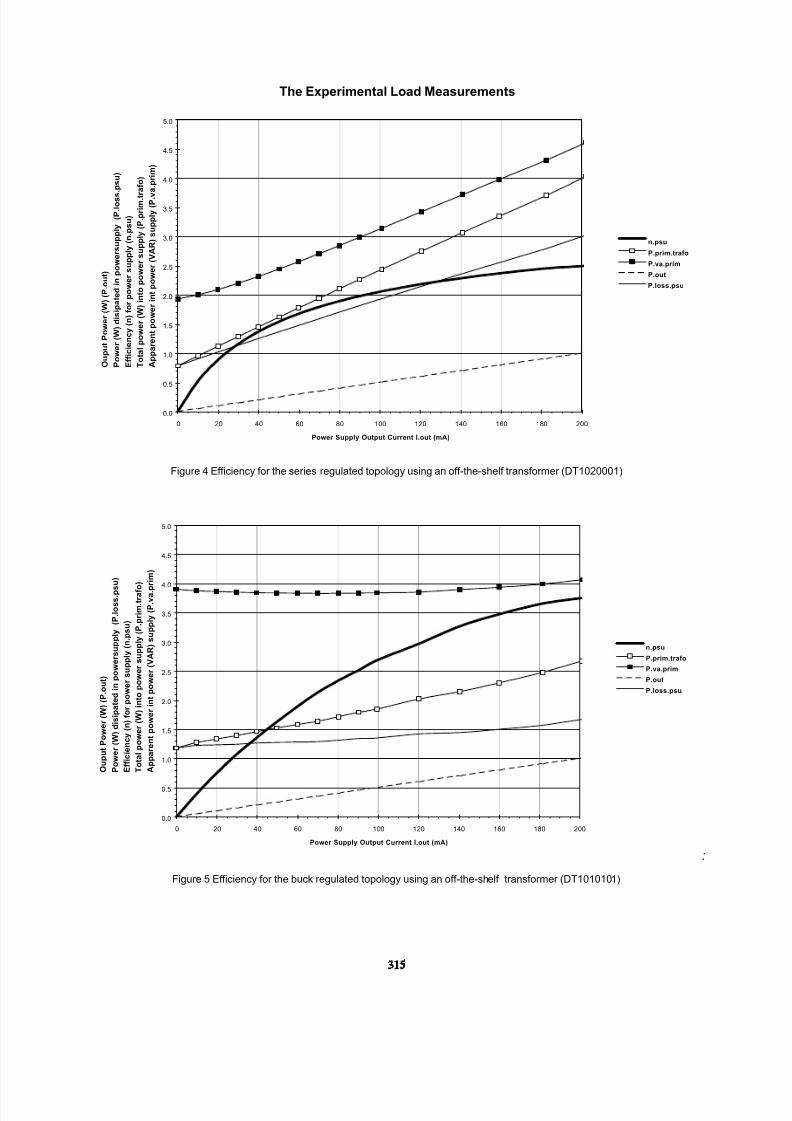
The Experimental Load Measurements
0.0
0.5
1.0
1.5
2.0
2.5
3.0
3.5
4.0
4.5
5.0
0 20 40 60 80 100 120 140 160 180 200
Power Supply Output Current I.out (mA)
O u p u t P o w e r ( W ) ( P . o u t )
P o w e r ( W ) d i s i p a t e d i n p o w e r s u p p l y ( P . l o s s
. p s u )
E f f i c i e n c y ( n ) f o r p o w e r s u p p l y ( n . p s u )
T o t a l p o w e r ( W ) i n t o p o w e r s u p p l y ( P . p r i m . t r a f o )
A p p a r e n t p o w e r i n t p o w e r ( V A R ) s u p p l y ( P . v
a . p r i m )
n.psu
P.prim.trafo
P.va.prim
P.out
P.loss.psu
Figure 4 Efficiency for the series regulated topology using an off-the-shelf transformer (DT1020001)
0.0
0.5
1.0
1.5
2.0
2.5
3.0
3.5
4.0
4.5
5.0
0 20 40 60 80 100 120 140 160 180 200
Power Supply Output Current I.out (mA)
O u p u t P o w e r ( W ) ( P . o u t )
P o w e r ( W ) d i s i p a t e d i n p o w e r s u p p l y ( P . l o s s . p s
u )
E f f i c i e n c y ( n ) f o r p o w e r s u p p l y ( n . p s u )
T o t a l p o w e r ( W ) i n t o p o w e r s u p p l y ( P . p r i m . t r a f o
)
A p p a r e n t p o w e r i n t p o w e r ( V A R ) s u p p l y ( P . v a . p
r i m )
n.psu
P.prim.trafo
P.va.prim
P.out
P.loss.psu
:
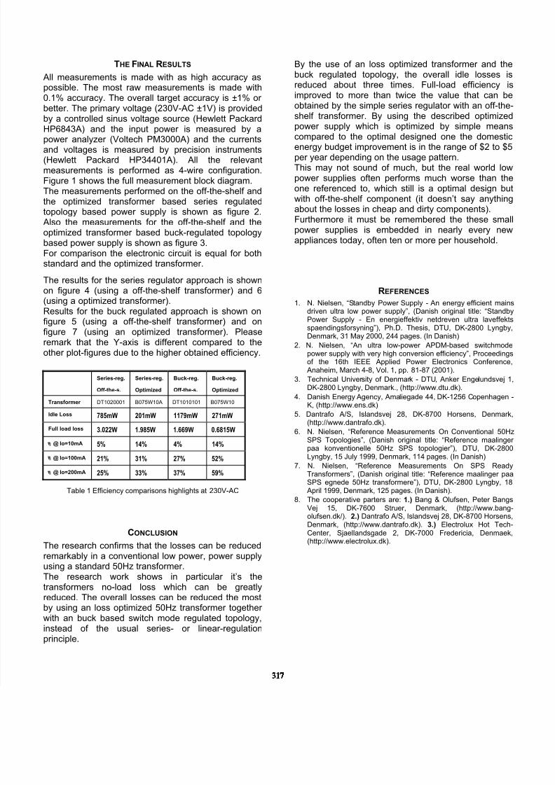
Figure 5 Efficiency for the buck regulated topology using an off-the-shelf transformer (DT1010101)
315

8/7/2019 Optimizing Efficiency on Conventional Transformer Based
http://slidepdf.com/reader/full/optimizing-efficiency-on-conventional-transformer-based 4/5
0.0
0.5
1.0
1.5
2.0
2.5
3.0
3.5
4.0
4.5
5.0
0 20 40 60 80 100 120 140 160 180 200
Power Supply Output Current I.out (mA)
O u p u t P o w e r ( W ) ( P . o u t )
P o w e r ( W ) d i s i p a t e d i n p o w e r s u p p l y ( P . l o s s . p s u )
E f f i c i e n c y ( n ) f o r p o w e r s u p p l y ( n . p s u )
T o t a l p o w e r ( W ) i n t o p o w e r s u p p l y ( P . p r i m . t r a f o )
A p p a r e n t p o w e r i n t p o w e r ( V A R ) s u p p l y ( P . v a . p r i m )
n.psu
P.prim.trafo
P.va.prim
P.out
P.loss.psu
Figure 6 Efficiency for the series regulated topology using an optimized transformer (B075W10A)
0.0
0.5
1.0
1.5
2.0
2.5
3.0
3.5
4.0
4.5
5.0
5.5
6.0
0 20 40 60 80 100 120 140 160 180 200
Power Supply Output Current I.out (mA)
O u p u t P o w e r ( W ) ( P . o u t )
P o w e r ( W ) d i s i p a t e d i n p o w e r s u p p l y ( P . l o s s . p s u )
E f f i c i e n c y ( n ) f o r p o w e r s u p p l y ( n . p s u )
T o t a l p o w e r ( W ) i n t o p o w e r s u p p l y ( P . p r i m . t r a f o )
A p p a r e n t p o w e r i n t p o w e r ( V A R ) s u p p l y ( P . v a . p r i m )
n.psu
P.prim.trafo
P.va.prim
P.out
P.loss.psu
Figure 7 Efficiency for the buck regulated topology using an optimized transformer (B075W10)
316
8/7/2019 Optimizing Efficiency on Conventional Transformer Based
http://slidepdf.com/reader/full/optimizing-efficiency-on-conventional-transformer-based 5/5
THE FINAL RESULTS
All measurements is made with as high accuracy aspossible. The most raw measurements is made with0.1% accuracy. The overall target accuracy is ±1% or better. The primary voltage (230V-AC ±1V) is providedby a controlled sinus voltage source (Hewlett PackardHP6843A) and the input power is measured by a
power analyzer (Voltech PM3000A) and the currentsand voltages is measured by precision instruments(Hewlett Packard HP34401A). All the relevantmeasurements is performed as 4-wire configuration.Figure 1 shows the full measurement block diagram.The measurements performed on the off-the-shelf andthe optimized transformer based series regulatedtopology based power supply is shown as figure 2.Also the measurements for the off-the-shelf and theoptimized transformer based buck-regulated topologybased power supply is shown as figure 3.For comparison the electronic circuit is equal for bothstandard and the optimized transformer.
The results for the series regulator approach is shownon figure 4 (using a off-the-shelf transformer) and 6(using a optimized transformer).Results for the buck regulated approach is shown onfigure 5 (using a off-the-shelf transformer) and onfigure 7 (using an optimized transformer). Pleaseremark that the Y-axis is different compared to theother plot-figures due to the higher obtained efficiency.
Series-reg.
Off-the-s.
Series-reg.
Optimized
Buck-reg.
Off-the-s.
Buck-reg.
Optimized
Transformer DT1020001 B075W10A DT1010101 B075W10
Idle Loss 785mW 201mW 1179mW 271mW
Full load loss 3.022W 1.985W 1.669W 0.6815W
η @ Io=10mA 5% 14% 4% 14%
η @ Io=100mA 21% 31% 27% 52%
η @ Io=200mA 25% 33% 37% 59%
Table 1 Efficiency comparisons highlights at 230V-AC
CONCLUSION
The research confirms that the losses can be reducedremarkably in a conventional low power, power supplyusing a standard 50Hz transformer.The research work shows in particular it’s thetransformers no-load loss which can be greatlyreduced. The overall losses can be reduced the mostby using an loss optimized 50Hz transformer together with an buck based switch mode regulated topology,instead of the usual series- or linear-regulationprinciple.
By the use of an loss optimized transformer and thebuck regulated topology, the overall idle losses isreduced about three times. Full-load efficiency isimproved to more than twice the value that can beobtained by the simple series regulator with an off-the-shelf transformer. By using the described optimizedpower supply which is optimized by simple means
compared to the optimal designed one the domesticenergy budget improvement is in the range of $2 to $5per year depending on the usage pattern.This may not sound of much, but the real world lowpower supplies often performs much worse than theone referenced to, which still is a optimal design butwith off-the-shelf component (it doesn’t say anythingabout the losses in cheap and dirty components).Furthermore it must be remembered the these smallpower supplies is embedded in nearly every newappliances today, often ten or more per household.
REFERENCES
1. N. Nielsen, “Standby Power Supply - An energy efficient mainsdriven ultra low power supply”, (Danish original title: “StandbyPower Supply - En energieffektiv netdreven ultra laveffektsspaendingsforsyning”), Ph.D. Thesis, DTU, DK-2800 Lyngby,Denmark, 31 May 2000, 244 pages. (In Danish)
2. N. Nielsen, “An ultra low-power APDM-based switchmodepower supply with very high conversion efficiency”, Proceedingsof the 16th IEEE Applied Power Electronics Conference,Anaheim, March 4-8, Vol. 1, pp. 81-87 (2001).
3. Technical University of Denmark - DTU, Anker Engelundsvej 1,DK-2800 Lyngby, Denmark., (http://www.dtu.dk).
4. Danish Energy Agency, Amaliegade 44, DK-1256 Copenhagen -K, (http://www.ens.dk)
5. Dantrafo A/S, Islandsvej 28, DK-8700 Horsens, Denmark,(http://www.dantrafo.dk).
6. N. Nielsen, “Reference Measurements On Conventional 50HzSPS Topologies”, (Danish original title: “Reference maalinger paa konventionelle 50Hz SPS topologier”), DTU, DK-2800Lyngby, 15 July 1999, Denmark, 114 pages. (In Danish)
7. N. Nielsen, “Reference Measurements On SPS ReadyTransformers”, (Danish original title: “Reference maalinger paaSPS egnede 50Hz transformere”), DTU, DK-2800 Lyngby, 18April 1999, Denmark, 125 pages. (In Danish).
8. The cooperative parters are: 1.) Bang & Olufsen, Peter BangsVej 15, DK-7600 Struer, Denmark, (http://www.bang-olufsen.dk/). 2.) Dantrafo A/S, Islandsvej 28, DK-8700 Horsens,Denmark, (http://www.dantrafo.dk). 3.) Electrolux Hot Tech-Center, Sjaellandsgade 2, DK-7000 Fredericia, Denmaek,(http://www.electrolux.dk).
317