optimization of the lithium insertion cell with silicon ...cell with silicon negative electrode for...
TRANSCRIPT
Optimization of the Lithium Insertion
Cell with Silicon Negative Electrode
for Automotive Applications
Rajeswari Chandrasekaran, Andy DrewsEnergy Storage Research Department. Research and Advanced Engineering Division
Ford Motor Company
COMSOL Conference, Boston, MA, Oct 14, 2011.
2
Related Publications
� Single Particle Model
� R. Chandrasekaran, A. Magasinski, G. Yushin, T.F. Fuller,
J. Electrochem. Soc. ,157 (10) A1139-A1151 (2010)
� Li-Silicon/ Separator/ Li Foil Cell Model
� R. Chandrasekaran, T.F. Fuller,
J. Electrochem. Soc. , 158 (8) A859-A871 (2011)
� Prior work pursued at Georgia Tech, sponsored by NASA Glenn
Research Center
3
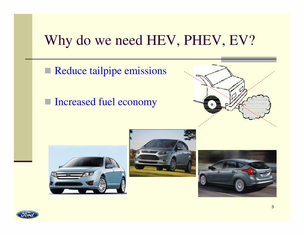
Why do we need HEV, PHEV, EV?
� Reduce tailpipe emissions
� Increased fuel economy
4
Automotive Adoption Metrics*:
Hierarchy of Needs
� Must work� Performance, life and robustness
� Must fit (Wh/liter) in the car� Package without compromising crash performance and
expected interior utility
� Must be cost effective� Life of vehicle performance
� Cost of fuel influence
� Cost of carbon influence
� Value based on power and/or energy density
� Value based on degree of uniformity
� Must be mass effective (Wh/kg and W/kg)� Increased range
* Courtesy: Ted Miller, Ford Motor Company
5
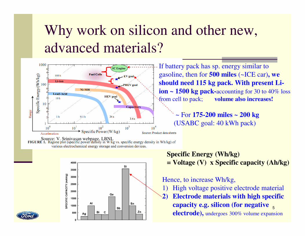
Why work on silicon and other new,
advanced materials?If battery pack has sp. energy similar to
gasoline, then for 500 miles (~ICE car), we
should need 115 kg pack. With present Li-
ion ~ 1500 kg pack-accounting for 30 to 40% loss
from cell to pack; volume also increases!
~ For 175-200 miles ~ 200 kg
(USABC goal: 40 kWh pack)
Specific Energy (Wh/kg)
= Voltage (V) x Specific capacity (Ah/kg)
Hence, to increase Wh/kg,
1) High voltage positive electrode material
2) Electrode materials with high specific
capacity e.g. silicon (for negative
electrode), undergoes 300% volume expansion
Source: V. Srinivasan webpage, LBNL
6
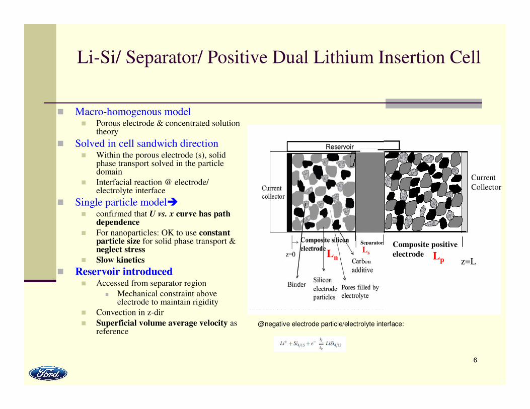
Li-Si/ Separator/ Positive Dual Lithium Insertion Cell
� Macro-homogenous model� Porous electrode & concentrated solution
theory
� Solved in cell sandwich direction� Within the porous electrode (s), solid
phase transport solved in the particle domain
� Interfacial reaction @ electrode/electrolyte interface
� Single particle model�� confirmed that U vs. x curve has path
dependence
� For nanoparticles: OK to use constant particle size for solid phase transport & neglect stress
� Slow kinetics
� Reservoir introduced� Accessed from separator region
� Mechanical constraint above electrode to maintain rigidity
� Convection in z-dir
� Superficial volume average velocity as reference
@negative electrode particle/electrolyte interface:
Composite positive
electrodeLn
Separator
Lp z=L
Ls
Current
Collector
7
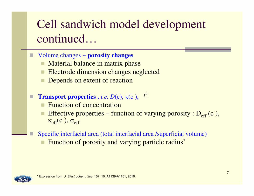
Cell sandwich model development
continued…
� Volume changes ~ porosity changes
� Material balance in matrix phase
� Electrode dimension changes neglected
� Depends on extent of reaction
� Transport properties , i.e. D(c), κ(c ),
� Function of concentration
� Effective properties – function of varying porosity : Deff (c ), κeff(c ), σeff
� Specific interfacial area (total interfacial area /superficial volume)
� Function of porosity and varying particle radius*
0t+
* Expression from J. Electrochem. Soc, 157, 10, A1139-A1151, 2010.
8
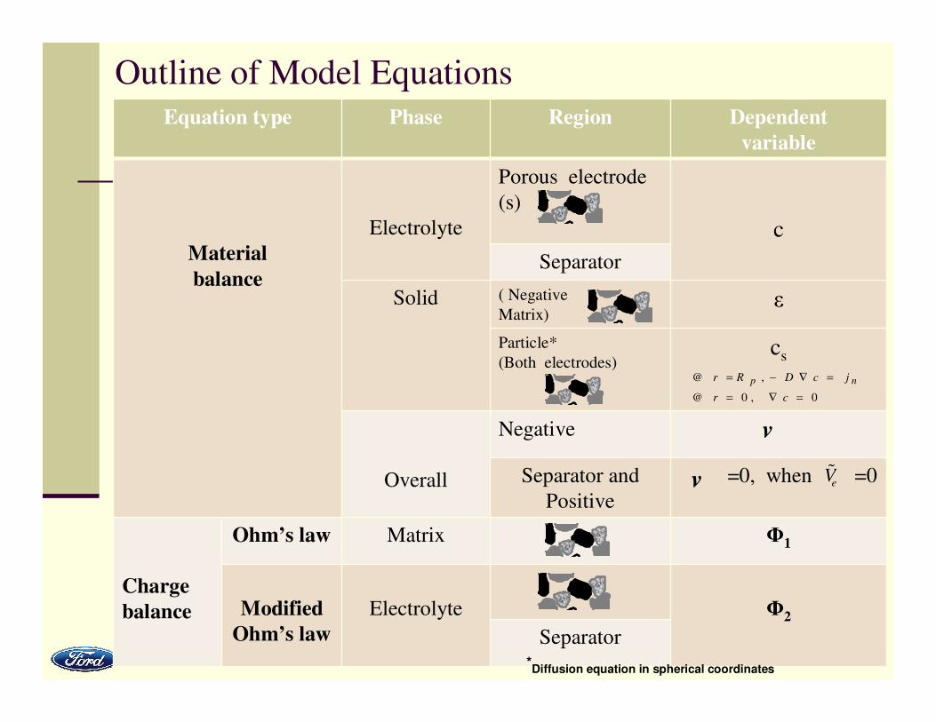
Outline of Model Equations
ε( Negative
Matrix)
Equation type Phase Region Dependent
variable
Material
balance
Electrolyte
Porous electrode
(s)
c
Separator
Solid
Particle*
(Both electrodes)cs
Overall
Negative
Separator and
Positive
=0, when =0
Charge
balance
Ohm’s law Matrix Φ1
Modified
Ohm’s law
Electrolyte Φ2
Separator
�v
�v
eV%
*Diffusion equation in spherical coordinates
0 ,0@
,@
=∇=
=∇−=
cr
jcDRr np
9
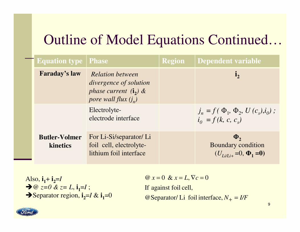
Outline of Model Equations Continued…
Equation type Phase Region Dependent variable
Faraday’s law Relation between
divergence of solution
phase current (i2) &
pore wall flux (jn)
i2
Butler-Volmer
kinetics
Electrolyte-
electrode interfacejn = f ( Φ1, Φ2, U (cs),i0) ;
i0 = f (k, c, cs)
For Li-Si/separator/ Li
foil cell, electrolyte-
lithium foil interface
Φ2
Boundary condition
(ULi/Li+ =0, Φ1 =0)
Also, i1+ i2=I
�@ z=0 & z= L, i1=I ;
�Separator region, i2=I & i1=0 I/FN
cLxx
=
=∇==
+interface, foil Li/ @Separator
cell, foilagainst If
0 , & 0@
10
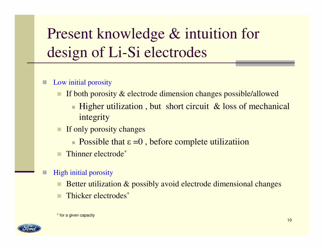
Present knowledge & intuition for
design of Li-Si electrodes
� Low initial porosity
� If both porosity & electrode dimension changes possible/allowed
� Higher utilization , but short circuit & loss of mechanical
integrity
� If only porosity changes
� Possible that ε =0 , before complete utilizatiion
� Thinner electrode*
� High initial porosity
� Better utilization & possibly avoid electrode dimensional changes
� Thicker electrodes*
* for a given capacity
11
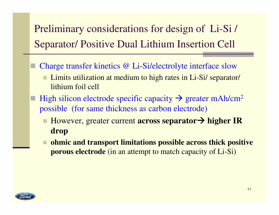
Preliminary considerations for design of Li-Si /
Separator/ Positive Dual Lithium Insertion Cell
� Charge transfer kinetics @ Li-Si/electrolyte interface slow
� Limits utilization at medium to high rates in Li-Si/ separator/
lithium foil cell
� High silicon electrode specific capacity � greater mAh/cm2
possible (for same thickness as carbon electrode)
� However, greater current across separator���� higher IR
drop
� ohmic and transport limitations possible across thick positive
porous electrode (in an attempt to match capacity of Li-Si)
12
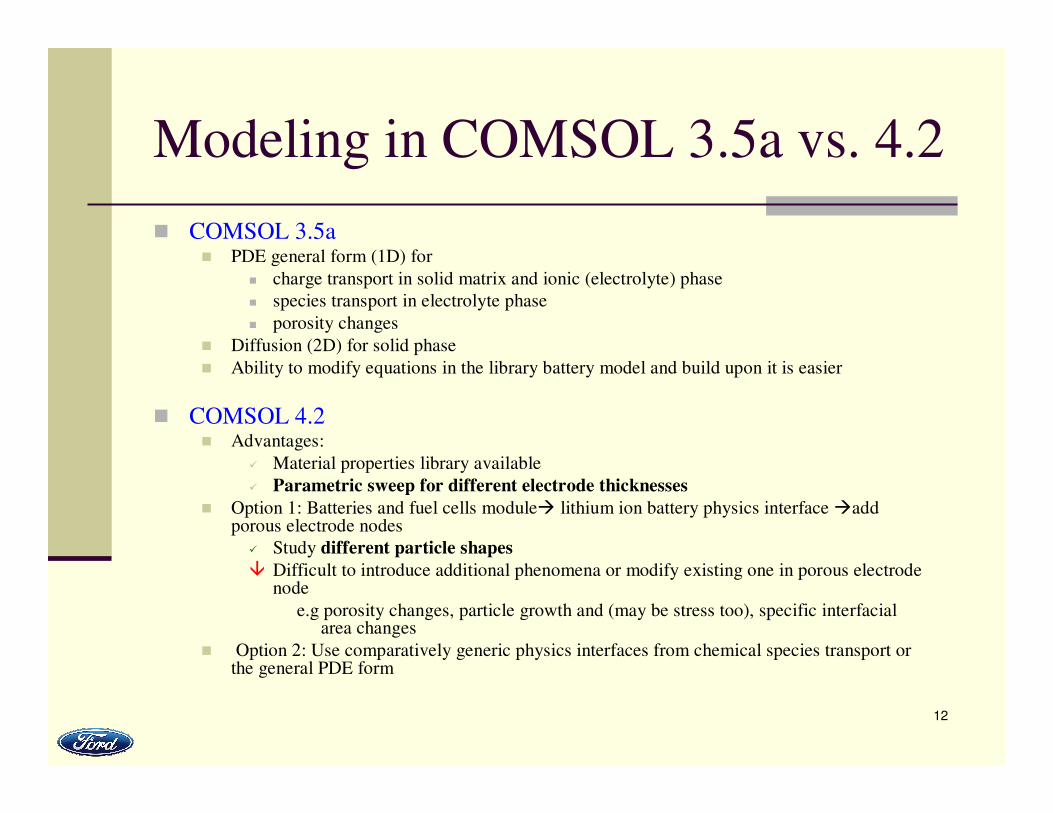
Modeling in COMSOL 3.5a vs. 4.2
� COMSOL 3.5a� PDE general form (1D) for
� charge transport in solid matrix and ionic (electrolyte) phase
� species transport in electrolyte phase
� porosity changes
� Diffusion (2D) for solid phase
� Ability to modify equations in the library battery model and build upon it is easier
� COMSOL 4.2� Advantages:
� Material properties library available
� Parametric sweep for different electrode thicknesses
� Option 1: Batteries and fuel cells module� lithium ion battery physics interface �add porous electrode nodes
� Study different particle shapes
� Difficult to introduce additional phenomena or modify existing one in porous electrode node
e.g porosity changes, particle growth and (may be stress too), specific interfacial area changes
� Option 2: Use comparatively generic physics interfaces from chemical species transport or the general PDE form
13
Results from Li-Si/separator/foil cell
(Simulations in COMSOL 3.5a)
Ref: R. Chandrasekaran, T.F. Fuller,
J. Electrochem. Soc. , 158 (8) A859-A871 (2011)
14
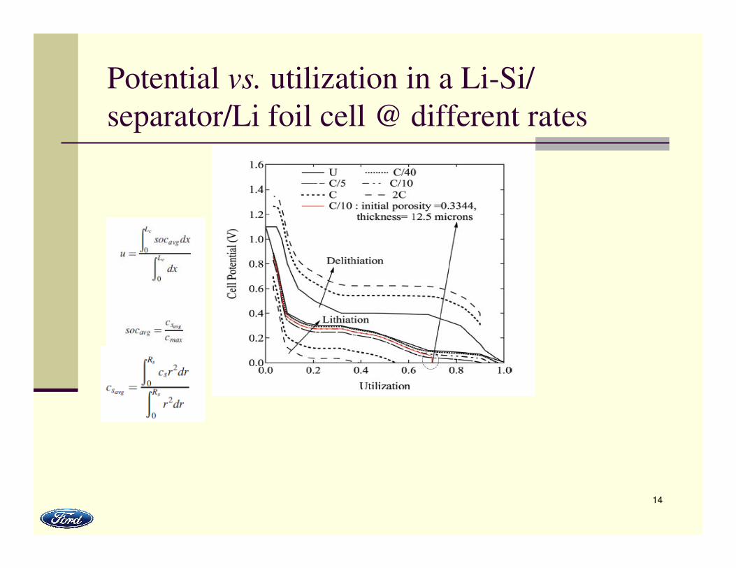
Potential vs. utilization in a Li-Si/
separator/Li foil cell @ different rates
15
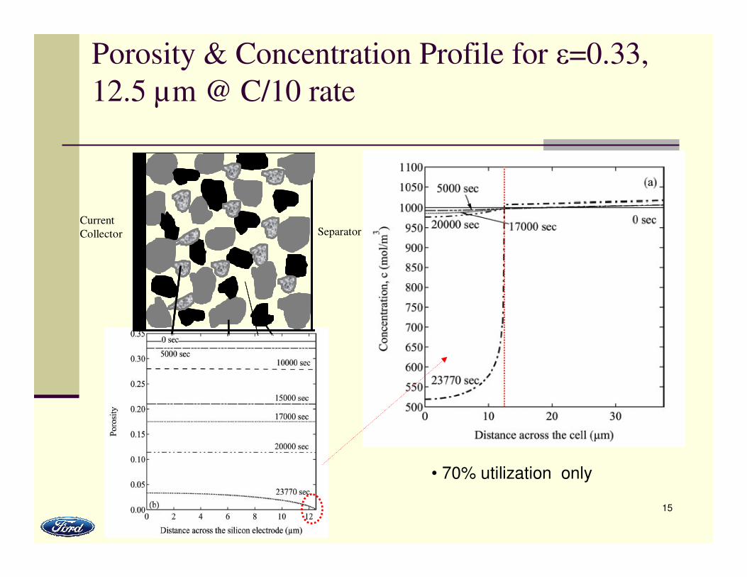
Porosity & Concentration Profile for ε=0.33,
12.5 µm @ C/10 rate
SeparatorCurrent
Collector
• 70% utilization only
16
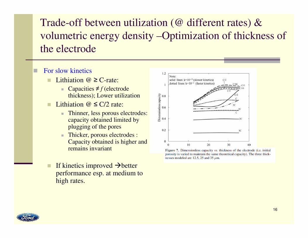
Trade-off between utilization (@ different rates) &
volumetric energy density –Optimization of thickness of
the electrode
� For slow kinetics
� Lithiation @ ≥ C-rate:
� Capacities ≠ f (electrode thickness); Lower utilization
� Lithiation @ ≤ C/2 rate:
� Thinner, less porous electrodes: capacity obtained limited by plugging of the pores
� Thicker, porous electrodes : Capacity obtained is higher and remains invariant
� If kinetics improved �better performance esp. at medium to high rates.
17
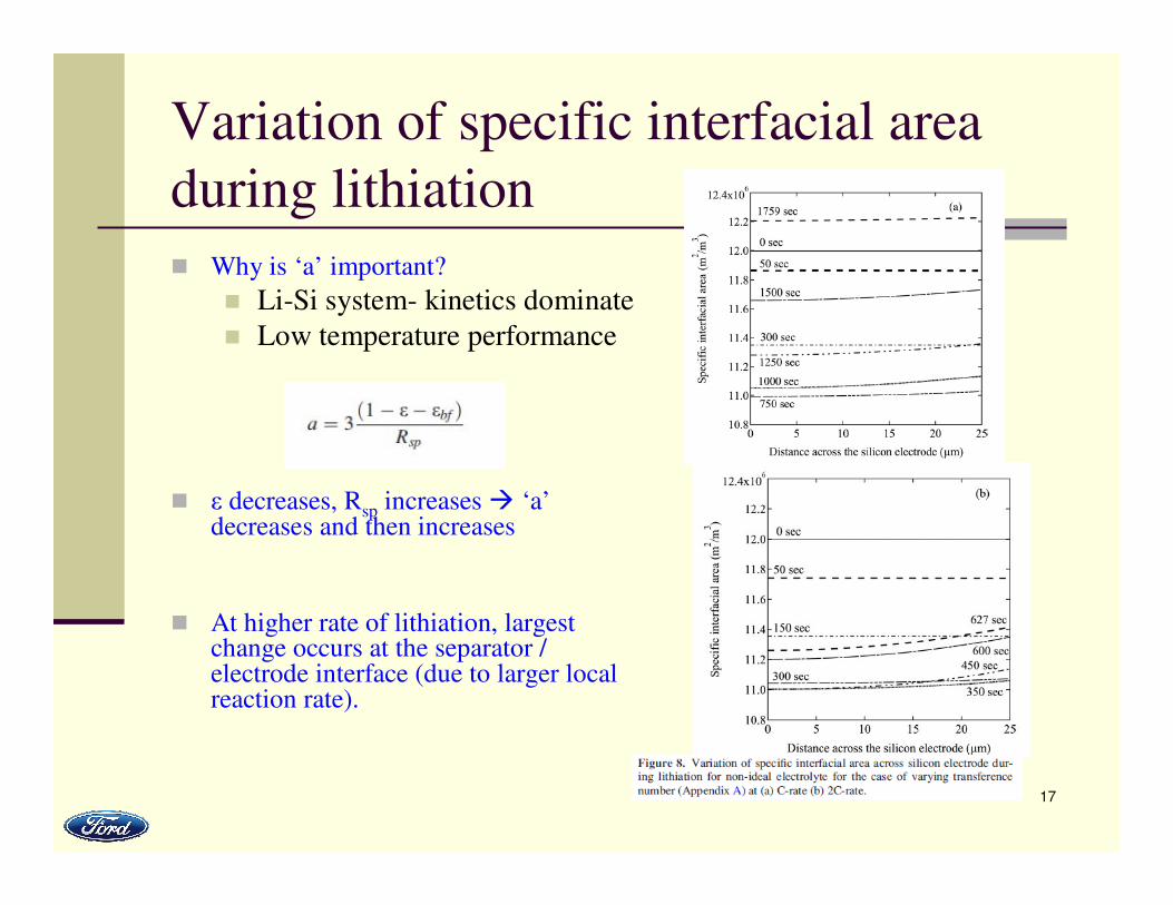
Variation of specific interfacial area
during lithiation
� Why is ‘a’ important?
� Li-Si system- kinetics dominate
� Low temperature performance
� ε decreases, Rsp increases � ‘a’decreases and then increases
� At higher rate of lithiation, largest change occurs at the separator / electrode interface (due to larger local reaction rate).
18
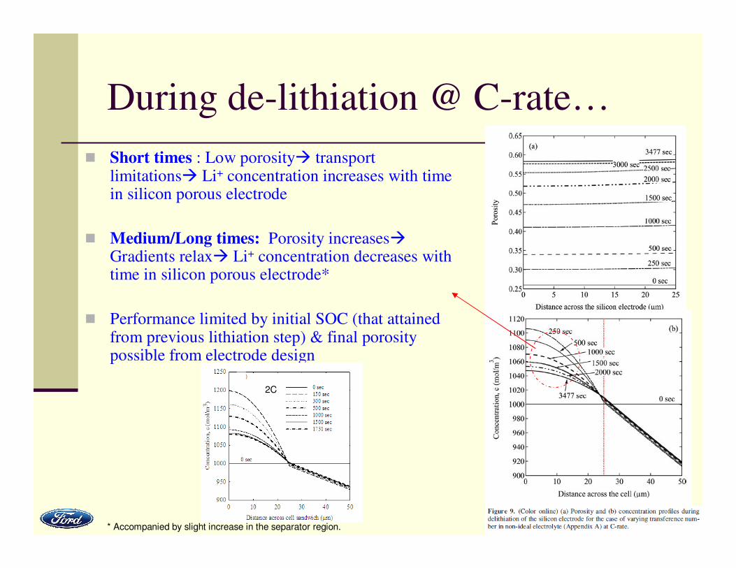
During de-lithiation @ C-rate…
� Short times : Low porosity� transport limitations� Li+ concentration increases with time in silicon porous electrode
� Medium/Long times: Porosity increases�Gradients relax� Li+ concentration decreases with time in silicon porous electrode*
� Performance limited by initial SOC (that attained from previous lithiation step) & final porosity possible from electrode design
* Accompanied by slight increase in the separator region.
2C
19
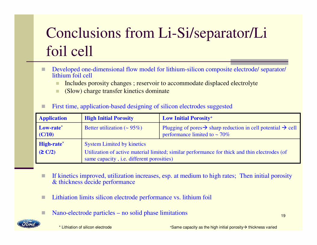
Conclusions from Li-Si/separator/Li
foil cell� Developed one-dimensional flow model for lithium-silicon composite electrode/ separator/
lithium foil cell
� Includes porosity changes ; reservoir to accommodate displaced electrolyte
� (Slow) charge transfer kinetics dominate
� First time, application-based designing of silicon electrodes suggested
� If kinetics improved, utilization increases, esp. at medium to high rates; Then initial porosity & thickness decide performance
� Lithiation limits silicon electrode performance vs. lithium foil
� Nano-electrode particles – no solid phase limitations
* Lithiation of silicon electrode +Same capacity as the high initial porosity� thickness varied
System Limited by kinetics
Utilization of active material limited; similar performance for thick and thin electrodes (of
same capacity , i.e. different porosities)
High-rate*
(≥ C/2)
Plugging of pores� sharp reduction in cell potential � cell
performance limited to ~ 70%
Better utilization (~ 95%)Low-rate*
(C/10)
Low Initial Porosity+High Initial PorosityApplication
20
Ongoing work
� Analysis of limitations in the Li-
Si/separator/positive insertion electrode cell under
different conditions
� Any other troubleshooting as required with
COMSOL 4.2!
21
Thank you!!
� Prof. Thomas F. Fuller (PhD Thesis Advisor)
� Mr. Ted Miller (manager)
� AUDIENCE
� Family