optimization algorithm-based approach for modelling large
TRANSCRIPT

1
Optimization Algorithm-Based Approach for Modelling Large
Deflection of Cantilever Beam Subjected to Tip Load
Fei Gao, Gaoyu Liu, Wei-Hsin Liao1
Department of Mechanical and Automation Engineering, The Chinese University of Hong Kong,
Shatin, NT, Hong Kong, China
Abstract Beam mechanism and beam theory have attracted substantial attention from researchers, as they have
been widely used in many fields such as compliant mechanisms and soft robots. The modeling of beam
mechanisms becomes complicated due to the geometric nonlinearity that is proved to be significant with
large deflection. A new method, called optimization algorithm-based approach (OABA), is proposed to
predict the large deflection of cantilever beams, in which an optimization algorithm is exploited to find
the locus of the beam tip. With the derived locus of the beam tip, the deflection curve of the cantilever
beam can be calculated. The optimization algorithm in this paper is embodied in a particle swarm
optimization (PSO) algorithm. Experimental results show that the proposed method can precisely predict
the deflection of the uniform and non-uniform cantilever beams. The maximum error is limited to 4.35%
when the normalized maximum transverse deflection reaches 0.75. Given that, the proposed OABA
would be a universal approach to model the large deflection of cantilever beams subjected to tip loads.
Keywords Cantilever beam model; Large deflection; Compliant mechanism; Variable cross-section; Particle
swarm optimization (PSO).
1. Introduction
Beam mechanism and beam theory have been widely used in many engineering fields such as
compliant mechanisms [1-7], flexible hinges [8-15], soft robots [16-21], piezoelectric beam-based energy
harvesters [22-25], and leaf springs [26-27]. Compliant mechanisms exploit the deflection of the beams
to transfer or transform the smooth and precise force and motion. Owing to utilizing fewer moveable
parts, compliant mechanisms have several merits over the traditional rigid-body mechanisms such as low
backlash and low wear. These advantages mentioned have attracted considerable attention from
researchers and industrials, and most of them devoted to promoting the study and use of compliant
mechanisms over the last decades. Leaf springs can be more compact and lightweight, compared with
coil springs, for providing the same stiffness and energy storage capability, so as to enable moveable
robots to provide the required elasticity at the same time meet the size and weight limitations.
To predict/characterize the deformation of beam mechanisms, vast researchers committed themselves
to devise and study the beam’s governing load-deformation relations. Linear beam theory has been
developed and widely used to derive the small deformation of cantilever beams subjected to tip loads.
However, once the deformation becomes large, nonlinearity will be raised in the governing equations
due to arc-length conservation and geometric nonlinearity. The linear beam theory is not valid in this
case. To handle that, researchers proposed alternative methods to model the large deflection of a
cantilever beam. These currently available methods can be generally categorized as elliptical integration
solution, finite element method, beam constraint model, energy-minimization-based solution, and
pseudo-rigid body model [28]. The elliptic integration solution is considered as the most accurate one,
which is used as a standard solution to evaluate other methods. It is noteworthy that the axial elongation
and shear of the beam are not considered in the elliptic integration solutions. Lyon and Howell [29]
developed the elliptic integration solution with no inflection point for a fixed-fixed beam, then Kimball
and Tsai [30] added an inflection point to the elliptic integration solution. Zhang and Chen [31]
established a comprehensive elliptic integration solution with the consideration of the number of
inflection points. With this method, the deflection of the cantilever beam can be precisely estimated
regardless of the load conditions and deflection modes.
Beam constraint model (BCM) [32] is a closed-form and parametric mathematical model, which is
used to capture the constraint characteristics of a cantilever beam in terms of the stiffness and errors
motion. Besides, in this model, the load conditions, initial and boundary conditions, and beam shapes
can be taken into account. Further, the nonlinearity associated with load equilibrium is also considered
here. The accuracy of this method can be guaranteed over a range of load and displacement. In particular,
1 Corresponding author.
Email address: [email protected]

2
the maximum transverse deflection is limited to ±0.1. Then Awtar and Sen [33] developed a nonlinear
strain energy formulation of the BCM based on principles of virtual work to derive the nonlinear load-
displacement relations for complex flexure mechanisms. Here the internal interaction force and the load
equilibrium for each constitute beam can be ignored thus significantly simplifying the calculation. To
increase the range of deflection, Chen et al. [34-35] developed a chained beam constant model (CBCM).
The flexible beam was divided into a few elements, and each element is characterized by BCM.
Howell and Midha [36] proposed to approximate the beam’s deflection with a pseudo-rigid body
model (PRB 1R). Specifically, the cantilever beam is modeled as two rigid links and an intermediate
torsion spring. One of the rigid links is fixed to the ground, and the other one is connected to the first one
by a pin joint. The length of each rigid link and the stiffness of the torsion spring are optimized to reduce
the tip locus errors between the derived results and the numerical elliptic integral data when the cantilever
beam is subject to a pure end force. To improve the accuracy and expand the load conditions, Kimball
and Tsai [37] developed PRB 2R that consists of three rigid links for modeling the deflection of a
cantilever beam with an inflection point. Yu et al. [38] also developed a PRB 2R to improve the accuracy
of PRB 1R. However, the parameters in the PRB 2R model are dependent on the loading conditions. Su
[39] established a PRB 3R model with high accuracy for a large range of deflection. Besides, the
parameters in this model are optimized to obtain high accuracy regardless of the load conditions [40-41].
To accurately predict the deflection of a cantilever beam with an inflection point, Yu et al. [42-43]
developed a PRB 5R, in which six rigid links are joint at five pin joints. Four of the pin joints are
accompanied by torsion springs, and the rest one is a free hinge. Unlike the aforementioned PRB 1R,
Verotti [44] developed a new one-DoF rigid body model, in which the stiffness coefficient was evaluated
based on strain energy, and the occurrence of an inflection point was also considered here.
The aforementioned methods exploited governing equations or approximated mathematic models to
derive the large deflection of a cantilever beam. Note that these methods are highly dependent on the
load conditions, boundary conditions, or assumptions for simplification. It is hard to guarantee the high
accuracy of these methods when the cantilever beam is subjected to a large range of load conditions.
Besides, the modification of these methods for different load conditions and the
calculation/implementation are complicated and tedious. In the last decades, artificial intelligence (AI)
encountered great progress. Researchers have proposed to use AI such as neural networks and
optimization algorithms to solve engineering problems to which traditional approaches are ineffective or
infeasible. The details of the systems such as the boundary conditions or load conditions in the above
models can be ignored, and the solutions can be obtained through performing sets of iterations. Shahabi
and Kuo [45] devised an artificial neural network (ANN) to solve the inverse kinematics solutions of the
dual-backbone continuum robot, and the forward kinematics solutions derived from PRBM were used to
train the ANN. Mohamad et al. [46] employed a PSO to identify the parameters in the dynamic model of
a flexible beam structure. Saffar et al. [47] developed an ANN to model the experimental data of an
aluminum cantilever beam. With this trained model, the natural frequencies of the system can be
predicted.
The objective of this paper is to propose a new approach to model the large deflection of a cantilever
beam when subjected to a combined tip load. Unlike the existing methods, this new method, called
OABA, utilized an optimization algorithm to find the locus of the beam tip through performing iteration
processes. The optimization algorithm is embodied in a PSO algorithm in this study. Then with that and
based on the Euler-Bernoulli (E-B) beam theory, the deflection curve of the cantilever beam can be
derived. The initial state of the cantilever beam is being straight, and the cross-section of the beam can
be uniform and non-uniform along the length. The work presented here is organized in the following
sequence. Section 2 introduces the working principles of the PSO algorithm, and then a PSO algorithm
is utilized to find the locus of the beam tip. Section 3 describes the experimental validation of the
presented approach. Section 4 discusses the extension of the presented method. For example, the
presented OABA may be employed to derive the deflection of a cantilever beam with initial curvature.
Finally, conclusions are made in terms of the presented study.
2. Particle swarm optimization-based approach to model large deflection of cantilever
beam
2.1 Particle swarm optimization
Swarm intelligence was proposed based on the collective behaviour of decentralized and self-
organized systems, which consist of a population of intelligent agents interacting with each other and the
environment. Each agent searches the environment with a certain degree random, while the
interaction/communication between each agent lead to “intelligence”-collective behaviour. Some well-
known examples can clearly show the working principles of swarm intelligent systems, for example, ant
colonies, bird flocking, and fish schooling. PSO is one kind of swarm intelligent algorithm, proposed by
3
Kennedy and Eberhart [48]. PSO is a heuristic global optimization method, which performs searching
processes via a swarm of particles that update their own positions and velocities based on individual
particles’ own searching experience and searching experience of the swarm. In the last decades, PSO
was widely used in many engineering fields [49], such as electrical and electronic engineering [50-51],
automatic control [52-53], and mechanical engineering [40, 54-55]. In our previous work, we have
exploited the PSO algorithm to optimize the dimension of an MR damper thus decreasing the energy
consumption at the same time providing the required damping force [56].
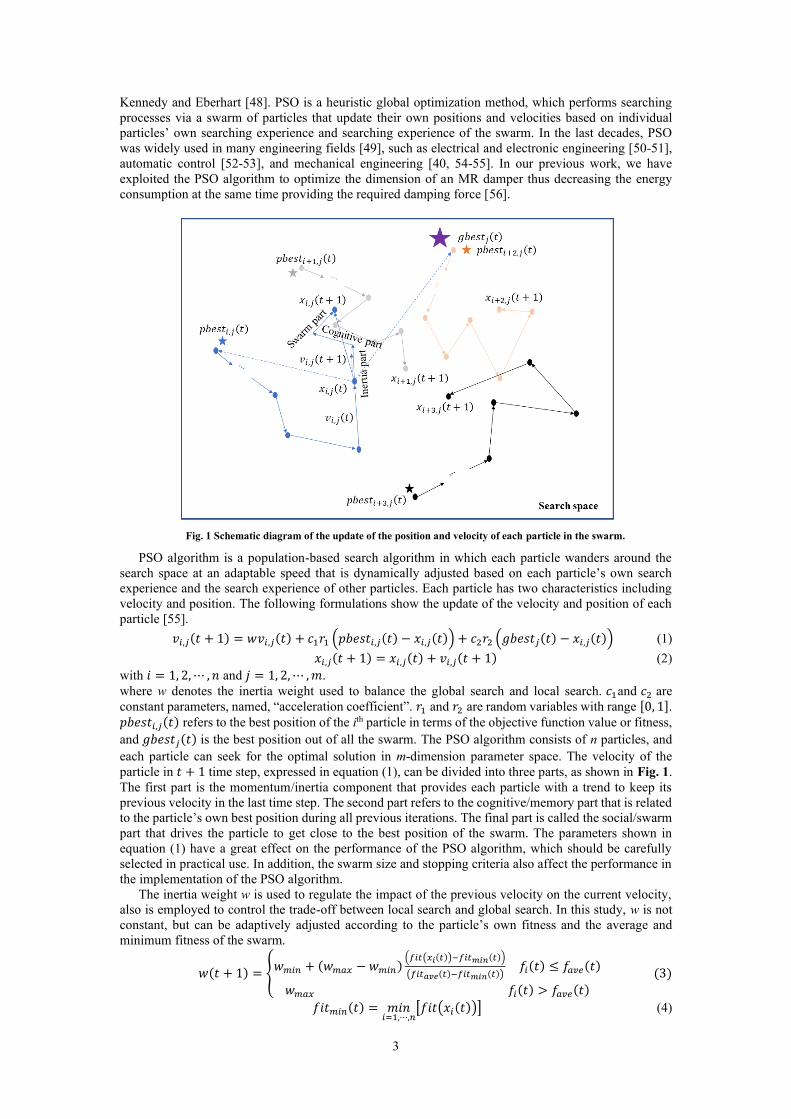
Fig. 1 Schematic diagram of the update of the position and velocity of each particle in the swarm.
PSO algorithm is a population-based search algorithm in which each particle wanders around the
search space at an adaptable speed that is dynamically adjusted based on each particle’s own search
experience and the search experience of other particles. Each particle has two characteristics including
velocity and position. The following formulations show the update of the velocity and position of each
particle [55].
𝑣𝑖,𝑗(𝑡 + 1) = 𝑤𝑣𝑖,𝑗(𝑡) + 𝑐1𝑟1 (𝑝𝑏𝑒𝑠𝑡𝑖,𝑗(𝑡) − 𝑥𝑖,𝑗(𝑡)) + 𝑐2𝑟2 (𝑔𝑏𝑒𝑠𝑡𝑗(𝑡) − 𝑥𝑖,𝑗(𝑡)) (1)
𝑥𝑖,𝑗(𝑡 + 1) = 𝑥𝑖,𝑗(𝑡) + 𝑣𝑖,𝑗(𝑡 + 1) (2)
with 𝑖 = 1, 2, ⋯ , 𝑛 and 𝑗 = 1, 2, ⋯ , 𝑚.
where w denotes the inertia weight used to balance the global search and local search. 𝑐1and 𝑐2 are
constant parameters, named, “acceleration coefficient”. 𝑟1 and 𝑟2 are random variables with range [0, 1]. 𝑝𝑏𝑒𝑠𝑡𝑖,𝑗(𝑡) refers to the best position of the ith particle in terms of the objective function value or fitness,
and 𝑔𝑏𝑒𝑠𝑡𝑗(𝑡) is the best position out of all the swarm. The PSO algorithm consists of n particles, and
each particle can seek for the optimal solution in m-dimension parameter space. The velocity of the
particle in 𝑡 + 1 time step, expressed in equation (1), can be divided into three parts, as shown in Fig. 1.
The first part is the momentum/inertia component that provides each particle with a trend to keep its
previous velocity in the last time step. The second part refers to the cognitive/memory part that is related
to the particle’s own best position during all previous iterations. The final part is called the social/swarm
part that drives the particle to get close to the best position of the swarm. The parameters shown in
equation (1) have a great effect on the performance of the PSO algorithm, which should be carefully
selected in practical use. In addition, the swarm size and stopping criteria also affect the performance in
the implementation of the PSO algorithm.
The inertia weight w is used to regulate the impact of the previous velocity on the current velocity,
also is employed to control the trade-off between local search and global search. In this study, w is not
constant, but can be adaptively adjusted according to the particle’s own fitness and the average and
minimum fitness of the swarm.
𝑤(𝑡 + 1) = {𝑤𝑚𝑖𝑛 + (𝑤𝑚𝑎𝑥 − 𝑤𝑚𝑖𝑛)
(𝑓𝑖𝑡(𝑥𝑖(𝑡))−𝑓𝑖𝑡𝑚𝑖𝑛(𝑡))
(𝑓𝑖𝑡𝑎𝑣𝑒(𝑡)−𝑓𝑖𝑡𝑚𝑖𝑛(𝑡)) 𝑓𝑖(𝑡) ≤ 𝑓𝑎𝑣𝑒(𝑡)
𝑤𝑚𝑎𝑥 𝑓𝑖(𝑡) > 𝑓𝑎𝑣𝑒(𝑡)
(3)
𝑓𝑖𝑡𝑚𝑖𝑛(𝑡) = 𝑚𝑖𝑛𝑖=1,⋯,𝑛
[𝑓𝑖𝑡(𝑥𝑖(𝑡))] (4)

4
𝑓𝑖𝑡𝑎𝑣𝑒(𝑡) =∑ 𝑓𝑖𝑡(𝑥𝑖(𝑡))𝑛
𝑖=1
𝑛 (5)
where 𝑤𝑚𝑖𝑛 and 𝑤𝑚𝑎𝑥 refer to the minimum inertia weight and the maximum inertia weight, respectively.
𝑓𝑖𝑡(𝑥𝑖(𝑡)) denotes the value of the fitness function of the ith particle.
For the implementation of the PSO algorithm, firstly the velocity and position of each particle will
be initialized with random values. Then based on the values of the fitness function of each individual
particle and the swarm, the velocity and position are updated in each time step, as illustrated in equations
(1)-(2). The PSO algorithm will be terminated while the maximum iteration number or the required
fitness is reached. Otherwise, the PSO algorithm will keep on performing iteration processes until the
termination condition is fulfilled.
2.2 Modelling large deflection of cantilever beam
Most of the existing methods proposed to directly derive the deflection of cantilever beams based on
some complex beam theory and specified boundary conditions [28-35]. Another widely used method
called the PRB model approximates the flexible cantilever beam by several rigid links that are connected
by pin joints and accompanied by torsion springs [36-44]. It is noteworthy that to obtain high accuracy,
the parameters in the PRB model such as the length of each link and stiffness of the torsion springs are
selected by optimization. However, in some special cases, this approach may not ensure acceptable
accuracy. Unlike the existing methods, Here, in this study, we use a PSO algorithm to find the planar
coordinates of the tip of a cantilever beam that subjects to tip loads. Then with the derived coordinates
of the tip and based on the E-B beam theory, the deflection curve of the cantilever beam can be obtained.
The schematic diagram of the optimization algorithm-based approach is presented in Fig. 2.
Fig. 2 Derivation of the locus of the tip when a cantilever beam is subjected to a combined tip load.
The cantilever beam is divided into nl units, and the curvature-moment relationship in each unit is
shown in Fig. 2. Here, the cantilever beam should be a long and slender beam, and only the bending
deformation induced by the moment is considered in each unit. The extension and compression of each
unit are ignored in this study. In addition, the cantilever beam has no initial curvature. The curvature of
each unit is proportional to the bending moment, according to the classical Euler-Bernoulli theory.
∆𝜃𝑙𝑖
∆𝑙=
1
𝜌𝑙𝑖
=𝑀𝑙𝑖
𝐸𝐼𝑙𝑖
, 𝑖 = 1,2, ⋯ , 𝑛𝑙 (6)
𝑀𝑙𝑖= 𝐹0𝑠𝑖𝑛(∅)(𝑄𝑥 − 𝑞𝑥𝑖−1
) − 𝐹0𝑐𝑜𝑠(∅)(𝑄𝑦 − 𝑞𝑦𝑖−1) + 𝑀0 (7)
where ∆𝑙 is the length of each unit. ∆𝜃𝑙𝑖 represents the variation of the slope in the ith unit. 𝜌𝑙𝑖
is the
curvature radius of the ith unit. 𝐸 and 𝐼𝑙𝑖 refer to the Young’s modulus and the moment of inertia of the
ith unit, respectively. 𝑀𝑙𝑖 is the moment acting on the ith unit. 𝐹0 and ∅ denote the tip force and the
inclination angle of the tip force, respectively. 𝑀0 refers to the tip moment. (𝑄𝑥 , 𝑄𝑦) is the coordinates
of the beam tip. 𝜃0 represents the slope of the beam tip. The slope at the segment point i+1th is given by
𝜃𝑙𝑖+1= 𝜃𝑙𝑖
+ ∆𝜃𝑙𝑖 (8)

5
As the stretching/compressing of the beam is ignored, the length of each unit is constant. The
coordinates (𝑞𝑥𝑖+1, 𝑞𝑦𝑖+1
) of the unit point i+1th can be calculated
𝑞𝑥𝑖+1= 𝑞𝑥𝑖
+ ∆𝑙𝑐𝑜𝑠𝜃𝑙𝑖 (9)
𝑞𝑦𝑖+1= 𝑞𝑦𝑖
+ ∆𝑙𝑠𝑖𝑛𝜃𝑙𝑖 (10)
The unit model shown in equations (6)-(10) are linear, and the curvature of the unit is linearly
proportional to the tip loads. The cantilever beam suffers from elastic deformation, and no plastic
deformation is induced here. However, as the beam arc-length conservation will result in nonlinearity in
the beam’s geometry, the transverse deflection, longitudinal deflection, and displacement of the tip are
nonlinearly proportional to the tip loads. The nonlinearity can be presented in the simulation and testing
results, as presented in Section 3. In this study, each particle in the PSO algorithm consists of three
elements including 𝑄𝑥, 𝑄𝑦 , and 𝜃0.
𝑥𝑖(𝑡) = [𝑄𝑥−𝑖(𝑡) 𝑄𝑦−𝑖(𝑡) 𝜃0−𝑖(𝑡)] (11)
Here, the fitness function in this PSO algorithm is given by
𝑓𝑖𝑡(𝑥𝑖(𝑡)) =
√(𝑄𝑥(𝑡)−𝑞𝑥𝑛𝑙(𝑡))
2+(𝑄𝑦(𝑡)−𝑞𝑦𝑛𝑙
(𝑡))2
𝑙+
|𝜃0(𝑡)−𝜃𝑙𝑛𝑙(𝑡)|
2𝜋 (12)
where (𝑞𝑥𝑛𝑙(𝑡), 𝑞𝑦𝑛𝑙
(𝑡)) are the derived coordinates of the beam tip. (𝑄𝑥(𝑡), 𝑄𝑦(𝑡)) are generated and
automatically updated by the PSO algorithm in each iteration. Substituting (𝑄𝑥(𝑡), 𝑄𝑦(𝑡)) into
equations (6)-(10), the (𝑞𝑥𝑛𝑙(𝑡), 𝑞𝑦𝑛𝑙
(𝑡)) can be calculated through performing nl iteration processes.
The error between (𝑄𝑥(𝑡), 𝑄𝑦(𝑡)) and (𝑞𝑥𝑛𝑙(𝑡), 𝑞𝑦𝑛𝑙
(𝑡)) is normalized with respect to the length of the
cantilever beam l. Also, the error between 𝜃0(𝑡) and 𝜃𝑙𝑛𝑙(𝑡) is normalized by the parameter search range,
2𝜋. The particle’s own best position 𝑝𝑏𝑒𝑠𝑡𝑖(𝑡), and the best position of the swarm 𝑔𝑏𝑒𝑠𝑡(𝑡) are
𝑝𝑏𝑒𝑠𝑡𝑖(𝑡) = 𝑎𝑟𝑔 𝑚𝑖𝑛𝑘=1,⋯,𝑡
[𝑓𝑖𝑡(𝑥𝑖(𝑘)) ] (13)
𝑔𝑏𝑒𝑠𝑡(𝑡) = 𝑎𝑟𝑔 𝑚𝑖𝑛𝑘=1,⋯,𝑡𝑖=1,⋯,𝑛
[𝑓𝑖𝑡(𝑥𝑖(𝑘)) ] (14)
Fig. 3 PSO algorithm-based approach for modelling the deflection of a cantilever beam.
The stopping criteria used in this study is given by
𝑓𝑖𝑡(𝑔𝑏𝑒𝑠𝑡(𝑡)) ≤ 𝑒𝑡ℎ, 𝑜𝑟 𝑡 = 𝑡𝑚𝑎𝑥 (15)

6
where 𝑒𝑡ℎ is the acceptable error, and 𝑡𝑚𝑎𝑥 refers to the maximum iteration number. When the above
condition is fulfilled, the iteration processes in the PSO algorithm will end.
With a given combined tip load [𝐹0 ∅ 𝑀0], the derivation of the locus of the beam tip can be
illustrated as follows:
1. Reset the values of the general parameters used in the PSO algorithm, 𝑐1, 𝑐2, n, m. Initialize
each particle in the swarm with random velocities 𝑣𝑖(0) = [𝑣𝑄𝑥−𝑖(0) 𝑣𝑄𝑦−𝑖
(0) 𝑣𝜃0−𝑖(0)]
and random positions 𝑥𝑖(0) = [𝑄𝑥−𝑖(0) 𝑄𝑦−𝑖(0) 𝜃0−𝑖(0)] . The velocities and positions
should be located in their search space, respectively, as shown in Fig.1.
2. Substituting 𝑥𝑖(0) = [𝑄𝑥−𝑖(0) 𝑄𝑦−𝑖(0) 𝜃0−𝑖(0)] into equations (6)-(12), the fitness value
of each particle can be calculated. Then taking those into equations (13)-(14), the individual
best fitness value 𝑓𝑖𝑡(𝑝𝑏𝑒𝑠𝑡𝑖(𝑡)) and global best fitness value 𝑓𝑖𝑡(𝑔𝑏𝑒𝑠𝑡(𝑡)) and the
corresponding position 𝑝𝑏𝑒𝑠𝑡𝑖(𝑡) and 𝑔𝑏𝑒𝑠𝑡(𝑡) can be derived.
3. With these derived parameters including 𝑝𝑏𝑒𝑠𝑡𝑖(𝑡) and 𝑔𝑏𝑒𝑠𝑡(𝑡), the inertia weight 𝑤(𝑡 + 1),
velocities 𝑣𝑖(𝑡 + 1), and positions of each particle 𝑥𝑖(𝑡 + 1) can be updated in each iteration,
according to equations (1)-(5).
4. Repeat steps 2 and 3 until the stopping criteria in equation (15) is achieved.
5. When the iteration is terminated, the coordinates and the slop of the beam tip are obtained,
[𝑄𝑥(𝑡) 𝑄𝑦(𝑡) 𝜃0(𝑡)] = 𝑔𝑏𝑒𝑠𝑡(𝑡). The derivation flow chart of the coordinates and the slop
of the beam tip is presented in Fig. 3.
3. Experimental validation of the optimization algorithm-based approach
3.1 Deflection of uniform beam
Fig. 4 Deflection measurements of a uniform cantilever beam. (a) Subjected to a pure force load, (b) Subjected to a
combined force and moment load.
To validate the proposed method, we develop a platform, as shown in Fig. 4, for testing the deflection
of a uniform beam. Then by comparing the tested results with the estimated results derived from the
optimization algorithm-based approach, the accuracy can be calculated. Two cases including subjected
to a pure force load and subjected to a combined force and moment load are investigated, as shown in
Fig.4. The normalized error between the simulation and the testing results is given by
𝑒𝑛𝑜𝑟𝑚 =𝑒𝑟𝑟𝑜𝑟
𝑙=
√(𝑄𝑥−𝑄𝑥𝑚)2+(𝑄𝑦−𝑄𝑦𝑚)2
𝑙 (16)
where (𝑄𝑥𝑚 , 𝑄𝑦𝑚) refers to the measured coordinates of the beam tip. During all testing, the maximum
deformation of the cantilever beam will not exceed the maximum allowable elastic deformation. When

7
the tip load is removed, the cantilever beam can restore to its initial shape. When the cantilever beam
experienced a pure force load (𝐹0 = 1.034 𝑁), the PSO algorithm can efficiently find the locus of the
beam tip after performing 26 iterations. The errors in each iteration and the derived locus of the beam tip
are presented in Fig. 5(a) and (b), respectively. Besides, substituting (𝑄𝑥 , 𝑄𝑦) into equations (6)-(10),
the deflection curves of the cantilever beam under different loads can be derived and presented in Fig.
5(b). The values of the parameters used in this study are listed in Table I.
Fig. 5 Derivation of the coordinates of beam tip based on the PSO algorithm. (a) Values of the fitness function in each
iteration, (b) 𝒈𝒃𝒆𝒔𝒕(𝒕) in each iteration and the defection curve corresponding to the final 𝒈𝒃𝒆𝒔𝒕. (𝑭𝟎 = 𝟔. 𝟗𝟓𝟖 𝑵, ∅ =
−𝟓𝝅
𝟔 , 𝑴𝟎 = 𝟎 𝑵𝒎)
Table I
Values of the parameters used in this study

8
Fig. 6 Comparison of the tip locus of the simulation and testing results. (Uniform cantilever beam subjected to a pure force
load)
Fig. 7 Comparison of the tip locus of the simulation and testing results. (Uniform cantilever beam subjected to a combined
force and moment load)
9
In case 1, angle ∅ can be regulated through adjusting the inclination angle of the cantilever beam, as
shown in Fig. 4(a). Here, four different angles ∅ are investigated, and the tip force ranges from 1.078 N
to 13.818 N. The force load consists of a set of weights. The comparison between the simulation results
and testing results is presented in Fig. 6. The maximum transverse deflection can reach about 0.75 when
angle ∅ is −5𝜋
6, and the maximum error is 3.97% when angle ∅ is −
2𝜋
3. While angle ∅ is −
𝜋
3, the
maximum transverse deflection is about 0.45, and the maximum error is about 1.44%.
In case 2, the cantilever beam experiences a combined tip force and moment load. Angle ∅ is fixed
to −𝜋
2, but the ratio of the force to the moment can be changed through adjusting the length of the lever
arm as shown in Fig. 4(b). The pulley fixed to the tip of the beam is considered as an extra weight, 𝐹𝑒.
In this case, the lever arm ranges from 10 mm to 40 mm. When the length of the lever arm is 10 mm, the
maximum transverse deflection is 0.64, and the maximum error is 2.17%, as shown in Fig. 7. While the
length of the lever arm is increased to 40 mm, the maximum transverse deflection is augmented to 0.71,
and the maximum error can reach 3.70%. In addition, a set of deflection curves when the non-uniform
cantilever beam experiences different combined tip force and moment loads are also plotted in Fig. 7.
As the directions of the tip force and tip moment are the same, no inflection point occurs in the deflection
curve.
Given the results shown in Figs. 6 and 7, we can conclude that the presented optimization algorithm-
based approach can precisely predict the large deformation of a uniform cantilever beam when it is
subjected to a combined tip load. Even the inclination angle of the force and ratio of force to moment
suffer from large variations, the maximum error between the estimated values and the tested results is
limited to 3.97%.
3.2 Deflection of non-uniform beam
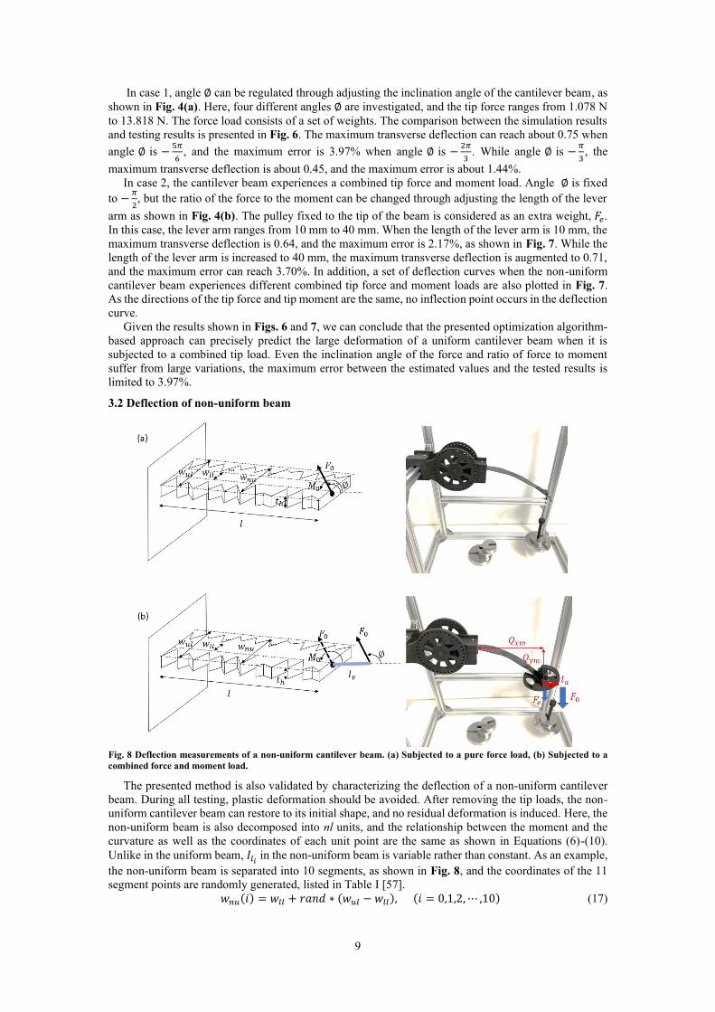
Fig. 8 Deflection measurements of a non-uniform cantilever beam. (a) Subjected to a pure force load, (b) Subjected to a
combined force and moment load.
The presented method is also validated by characterizing the deflection of a non-uniform cantilever
beam. During all testing, plastic deformation should be avoided. After removing the tip loads, the non-
uniform cantilever beam can restore to its initial shape, and no residual deformation is induced. Here, the
non-uniform beam is also decomposed into nl units, and the relationship between the moment and the
curvature as well as the coordinates of each unit point are the same as shown in Equations (6)-(10).
Unlike in the uniform beam, 𝐼𝑙𝑖 in the non-uniform beam is variable rather than constant. As an example,
the non-uniform beam is separated into 10 segments, as shown in Fig. 8, and the coordinates of the 11
segment points are randomly generated, listed in Table I [57].
𝑤𝑛𝑢(𝑖) = 𝑤𝑙𝑙 + 𝑟𝑎𝑛𝑑 ∗ (𝑤𝑢𝑙 − 𝑤𝑙𝑙), (𝑖 = 0,1,2, ⋯ ,10) (17)

10
where 𝑤𝑙𝑙 and 𝑤𝑢𝑙 denote the lower and upper limits of the width, respectively. In this subsection, also
two cases including subjected to a pure force load and subjected to a combined tip force and moment
load are studied. In case 1, four different angles ∅ including −𝜋
3, −
𝜋
2, −
2𝜋
3, and −
5𝜋
6, are investigated,
and the tip force ranges from 1.078 N to 13.818 N. The simulation and testing results for different loads
are plotted in Fig. 9. When angle ∅ is −𝜋
3, the maximum transverse deflection is 0.443, and the maximum
error is 1.73%. Then the maximum transverse deflection is increased to 0.746 when angle is changed to
−5𝜋
6. The maximum error is 3.63%.
When the non-uniform cantilever beam suffers from a combined force and moment load, the locus
of the beam tip is plotted in Fig. 10. The ratio of the force to the moment is adjusted by changing the
length of the lever arm, as shown in Fig. 8(b). In this case, angle ∅ is fixed to −𝜋
2, and four different
lever arms are studied. The pulley fixed to the tip of the beam is considered as an extra weight, 𝐹𝑒. When
the length of the lever arm is set to 40 mm, the maximum transverse deflection is 0.696, and the maximum
error is 4.35%. In addition, a set of deflection curves when the non-uniform cantilever beam experiences
different loads are also plotted in Fig. 10.
According to the results plotted in Figs. 9 and 10, we can conclude that the proposed optimization
algorithm-based approach can characterize the large deflection of a non-uniform cantilever beam when
subjected to tip loads with high accuracy. Despite changing the inclination angle of the force and the
ratio of force to moment, the maximum error is limited to 4.35%.
Fig. 9 Comparison of the tip locus of the simulation and testing results. (Non-uniform cantilever beam subjected to a pure
force load)
4. Discussions Note that as an example, in this paper, we implement a PSO algorithm to find the locus of the tip
when the cantilever beam is subjected to different tip loads. Particles in the swarm of the PSO algorithm
can gradually approach the solution through updating their own positions and velocities based on the
“intelligence” -collective behaviour. In addition to PSO algorithm, the optimization algorithm can be
other types of algorithm with the same function such as genetic optimization, ant colony optimization,
and neural network algorithms.
In the unit model, equations (6)-(10), only the bending deformation is considered here. However, in
some cases, when the cantilever beam is made of stretchable materials, the elongation, shear deformation,
or compression deformation in longitudinal direction cannot be ignored [14, 19, 58-59]. To handle that,
we need to modify the unit model, equations (6)-(10), to consider the deformation along the neutral plane.

11
Then we still can employ the presented optimization algorithm (OABA) to find the locus of the tip. This
part will be further studied in the future.
Fig. 10 Comparison of the tip locus of the simulation and testing results. (Non-uniform cantilever beam subjected to a
combined force and moment load)
The cantilever beam studied in this work is initially straight and without curvature. However, in some
cases, the cantilever beam is with initial curvature, as studied in [60-61]. The curvature-moment
relationship in a unit, equation (6), should be updated to consider the initial curvature. The feasibility of
applying the presented OABA to predict the deflection of a cantilever beam with initial curvature will be
verified.
In addition, this presented method is used to characterize the kinematic deformation of the cantilever
beam here. In future work, we will check whether this method can be employed to predict the dynamic
motion of a cantilever beam [57, 62-65]. The inertia force and damping force will be considered in the
unit model.
5. Conclusions In this paper, we proposed a novel method, called optimization algorithm-based approach (OABA),
to predict/characterize the large deformation of a cantilever beam when subjecting tip loads. Unlike the
other existing approaches, this approach utilized an optimization algorithm (PSO algorithm) to find the
locus of the beam tip. When the stopping criteria is fulfilled, the iteration process will be terminated, and
then coordinates of the tip are obtained. Substituting the coordinates of the tip into the unit model, the
deflection curve of the cantilever beam can be derived. To validate the presented method, we developed
a platform to test the deflection of a uniform and a non-uniform cantilever beams when they experience
a pure force load and a combined force and moment load, respectively. Comparing the simulated and
testing results, we can find that the presented method can predict the deflections of the uniform and the
non-uniform cantilever beams with high accuracy. In particular, the maximum error is limited to 3.97%
for the uniform cantilever beam when the maximum transverse deflection reaches 0.75. While for the
non-uniform beam, the maximum error is 4.35% when the maximum transverse deflection reaches 0.746.
Given that, the OABA method can be regarded as a universal method for modelling the large deflection
of uniform and non-uniform beams.
Acknowledgements
This work is supported by Research Grants Council (Project No. CUHK14210019) and the Innovation
and Technology Commission (Project No. ITS/367/18) of Hong Kong Special Administrative Region,
China and in part by Hong Kong Centre for Logistics Robotics of InnoHK.

12
Appendix A
Codes in MATLAB for implementing the PSO-based approach
(1) Main.m
clear;
clc;
clear global leng thic wid E Q_x Q_y F0 M0 fai theta0 numbs inertia errori xt Pbest;
%%%%% values of the parameters of the cantilever beam %%%%%%%%%
global leng thic wid E Q_x Q_y F0 M0 fai theta0 numbs inertia Pbest
leng=180*10^(-3); %length of the cantilever beam
thic=1.15*10^(-3); %thickness of the cantilever beam
E=45.36*10^9; %Young's modulus of the cantilever beam
numbs=200; %nums:number of the unit segments
mode=1; %model=1 uniform cantilever beam,
%model=2 non-uniform cantilever beam
if mode==1;
for i=1:numbs
wid(i)=25*10^(-3); %uniform cantilever beam
end
else
n_sigm=10; %number of the segment
wid_n=[22.6,26.9,30.0,22.8,22.8,26.8,28.1,20.8,23.7,28.1,29.6]*10^(-3);
for i=1:numbs
nl=floor(i/(numbs/n_sigm));
nd=rem(i,(numbs/n_sigm));
if nd>0
wid(i)=wid_n(nl+1)+nd/(numbs/n_sigm)*(wid_n(nl+2)-wid_n(nl+1
else
wid(i)=wid_n(nl+1);
end
end
end
inertia=1/12.*wid*thic.^3; %moment of inertia
%(Q_x Q_y)the coordinates of the tip
F_i=20;
F0=F_i*9.8*50*10^(-3)+9.8*10*10^(-3); %F0: tip force
lever_a=0;
M0=-F0*lever_a*10*10^(-3); %MO: tip moment
fai_i=5;
fai=fai_i*(-pi/6); %fai: the direction of the tip Force
%theta0: the tip slope angle
%%%%%% solving processes %%%%%%%%%%%
global errori xt
xL=[-leng leng;-leng leng; -pi pi]; %the upper and lower limits of the parameters
%Q_x, Q_y, theta0 (output of PSO)
N=100; %number of particles in PSO
c1=0.2; %constant parameters in PSO
c2=c1; %constant parameters in PSO
wmax=0.8; %the maximum inertia weight in PSO
wmin=0.6; %the minimum inertia weight in PSO
max_step=50; %the maximum iteration number
vd=3; %dimension of the input in PSO
[xm,fv] = PSO(@inversemodel,N,c1,c2,wmax,wmin,max_step,vd,xL);
(2) PSO.m
………………….
(3) unit_model.m
…………………. (All codes will be provided after this manuscript has been accepted for publication)
References
[1] L.L. Howell, Compliant mechanisms, John Wiley & Sons, New York, NY, 2001.
[2] Q.T. Aten, S.A. Zirbel, B.D. Jensen, and L.L. Howell, A numerical method for position analysis of compliant mechanisms
with more degrees of freedom than inputs, ASME J. Mech. Des. 133 (2011) 061009. [3] G. Chen and Y. Du, Double-young tristable mechanism, ASME J. Mech. Rob. 5 (2013) 011007.
[4] G. Hao and H. Li, Nonlinear analytical modeling and characteristic analysis of a class of compound multibeam parallelogram
mechanisms, ASME J. Mech. Rob. 7 (2015) 041016. [5] O.A. Turkkan and H.J. Su, A general and efficient multiple segment method for kinetostatic analysis of planar compliant
mechanisms, Mech. Mach. Theory 112 (2017) 205-217.
[6] H. Malaeke and H. Moeenfard, A novel flexure beam module with low stiffness loss in compliant mechanisms, Precis Eng 48 (2017) 216-233.

13
[7] S. Wu, Z. Shao, H. Su, and H. Fu, An energy-based approach for kinetostatic modeling of general compliant mechanisms, Mech. Mach. Theory 142 (2019) 103588.
[8] J. Guo and K.M. Lee, Compliant joint design and flexure finger dynamic analysis using an equivalent pin model, Mech. Mach.
Theory 70 (2013) 338-353. [9] S. Šalini c, A. Nikoli c, A new pseudo-rigid-body model approach for modeling the quasi-static responses of planar flexure-
hinge mechanisms, Mech. Mach. Theory 124 (2018) 150-161.
[10] L.U. Odhner and A.M. Dollar, The smooth curvature model: an efficient representation of Euler–Bernoulli flexures as robot joints, IEEE Trans. Robotics 28 (4) (2012) 761-772.
[11] Z. Xie, L. Qiu, and D. Yang, Design and analysis of a variable stiffness inside-deployed lamina emergent joint, Mech. Mach.
Theory 120 (2018) 166-177. [12] M. Verotti, Analysis of the center of rotation in primitive flexures: Uniform cantilever beams with constant curvature, Mech.
Mach. Theory 97 (2016) 29-50.
[13] P.P. Valentini, M. Cirelli, and E. Pennestrì, Secend-order approximation pseudo-rigid model of flexure hinge with parabolic variable thickness, Mech. Mach. Theory 136 (2019) 178-189.
[14] V.K. Venkiteswaran and H.J. Su, A three-spring pseudorigidbody model for soft joints with significant elongation effects,
ASME J. Mech. Rob. 8 (2016) 061001. [15] P. Kuresangsai and M.O.T. Cole, Kinematic modeling and design optimization of flexture-jointed planar mechanisms using
polynomial bases for flexure curvature, Mech. Mach. Theory 132 (2019) 80-97.
[16] T. Fang, Y. Zhou, S. Li, M. Xu, H. Liang, W. Li, and S. Zhang, Theoretical and experimental study on a compliant flipper-leg during terrestrial locomotion, Bioinspir. Biomim 11 (2016) 056005.
[17] G.P. Jung, H.C. Choi, K.J. Cho, The effect of leg compliance in multi-directional jumping of a flea-inspired mechanism,
Bioinspir. Biomim 12 (2017) 026006. [18] W. Wei and N. Simaan, Modeling, force sensing, and control of flexible cannulas for microstent delivery, ASME J. Dyn.
Syst. Meas. Control 134 (2012) 041004.
[19] A. Demario, and J. Zhao, Development and analysis of a three-dimensional printed miniature walking robot with soft joints and links, ASME J. Mech. Rob. 10 (2018) 041005.
[20] Y. Zhong, Z. Li, and R. Du, A novel robot fish with wire-driven active body and compliant tail, IEEE/ASME Trans. Mechatronics 22 (4) (2017) 1633-1643.
[21] K.P. Ashwin and A. Ghosal, A soft-robotic end-effector for independently actuating endoscopic catheters, ASME J. Mech.
Rob. 11 (2019) 061004. [22] I. Izadgoshasb, Y.Y. Lim, N. Lake, L. Tang, R.V. Padilla, and T. Kashiwao, Optimizing orientation of piezoelectric
cantilever beam for harvesting energy from human walking, Energy Convers Manage 161 (2018) 66-73.
[23] F. Gao, G. Liu, B. L.H. Chung, H.H.T. Chan, and W.H. Liao, Macro fiber composite-based energy harvester for human knee, Appl. Phys. Lett. 115 (2019) 033901.
[24] R. Patel, S. McWilliam, and A. A. POPOV, Optimization of piezoelectric cantilever energy harvesters including non-linear
effects, Smart Mater. Struct 23 (2014) 085002. [25] Y. Kuang, Z. Yang, and M. Zhu, Design and characterisation of a piezoelectric knee-joint energy harvester with frequency
up-conversion through magnetic plucking, Smart Mater. Struct. 25 (2016) 085029.
[26] M.K. Shepherd and E.J. Rouse, The VSPA foot: a quasi-passive ankle-foot prosthesis with continuously variable stiffness, IEEE Trans. Rehabil. Eng. 25 (12) (2017) 2375-2386.
[27] J. Wu, Z. Wang, W. Chen, Y. Wang, and Y. Liu, Design and validation of a novel leaf spring based variable stiffness joint
with reconfigurability, IEEE/ASME Trans. Mechatronics (2020) DOI: 10.1109/TMECH.2020.2995533 [28] M. Ling, L.L. Howell, J. Cao, and G. Chen, Kinetostatic and dynamic modeling of flexure-based compliant mechanisms: a
survey, Appl Mech Rev 72 (2020) 030802.
[29] S.M. Lyon and L.L. Howell, A Simplified Pseudo-Rigid-Body Model for Fixed-Fixed Flexible Segments, ASME Paper No. DETC2002/ MECH (2002) 34203.
[30] K. Mattiasson, Numerical results from large deflection beam and frame problems analysed by means of elliptic integrals, Int.
J. Numer. Methods Eng., 17 (1) (1981) 145–153. [31] A.M. Zhang and G.M. Chen, A comprehensive elliptic integral solution to the large deflection problems of thin beams in
compliant mechanisms, ASME J. Mech. Rob. 5 (2) (2013) 021006.
[32] S. Awtar and S. Sen, A generalized constraint model for two-dimensional beam flexures: nonlinear load-displacement formulation, ASME J. Mech. Des. 132 (2010) 081008.
[33] S. Awtar and S. Sen, A generalized constraint model for two-dimensional beam flexures: nonlinear strain energy
formulation, ASME J. Mech. Des. 132 (2010) 081009. [34] G. Chen and R. Bai, Modeling large spatial deflections of slender bisymmetric beams in compliant mechanisms using
chained spatial-beam constraint model, ASME J. Mech. Rob. 8 (2016) 041011.
[35] F. Ma and G. Chen, Modeling large planar deflections of flexible beams in compliant mechanisms using chained beam-constraint-model, ASME J. Mech. Rob. 8 (2016) 021018.
[36] L.L. Howell and A. Midha, Parametric deflection approximations for end-loaded, large-deflection beams in compliant
mechanisms, ASME J. Mech. Des. 117 (1) (1995) 156-165.
[37] C. Kimball and L.W. Tsai, Modeling of flexural beams subjected to arbitrary end loads, ASME J. Mech. Des., 124 (2)
(2002) 223–235.
[38] Y.Q. Yu, Z.L. Feng, and Q.P. Xu, A pseudo-rigid-body 2R model of flexural beam in compliant mechanisms, Mech. Mach. Theory 15 (2012) 18-33.
[39] H.J. Su, A pseudorigid-body 3r model for determining large deflection of cantilever beams subject to tip loads, ASME J.
Mech. Rob. 1 (2009) 021008. [40] G. Chen, B. Xiong, and X. Huang, Finding the optimal characteristic parameters for 3R pseudo-rigid-body model using an
improved particle swarm optimizer, Precis Eng 35 (2011) 505-511.
[41] V.K. Venkiteswaran and H.J. Su, A parameter optimization framework for determining the pseudo-rigid-body model of cantilever-beams, Precis Eng 40 (2015) 46-54.
[42] Y.Q. Yu and S.K. Zhu, 5R pseudo-rigid-body model for inflection beams in complaint mechanisms, Mech. Mach. Theory
116 (2017) 501-512. [43] S.K. Zhu and Y.Q. Yu, Pseudo-rigid-body model for the flexural beam with an inflection point in compliant mechanisms,
ASME J. Mech. Rob. 9 (2017) 031005.

14
[44] M. Verotti, A pseudo-rigid-body model based on finite displacements and strain energy, Mech. Mach. Theory 149 (2020) 103811.
[45] E. Shahabi and C.H. Kuo, Solving inverse kinematics of a planar dualbackbone continuum robot using neural network,
in Proc. Eur. Conf. Mechanism Sci. (2019) 355–361. [46] M. Mohamad, M.O. Tokhi, S.F. Toha, I.A. Latiff, Particle swarm modelling of a flexible beam structure, in Proc. 3rd UK
Sim European Symposium Computer Modeling and Simulation (2009) 31-36.
[47] A.A.A. Saffar, A.A. Diwan, L.S.A. Ansari, and A. Alkhatat, Experimental and artificial neural network modeling of natural frequency of stepped cantilever shaft, Journal of Mechanical Engineering Research and Developments 43 (4) (2020) 299-
309.
[48] J. Kennedy and R. Eberhart, Particle swarm optimization, in Proc. IEEE International Conference on Neural Networks, 4 (1995) 1942–1948.
[49] Y. Zhang, S. Wang, and G. Ji, A comprehensive survey on particle swarm optimization: algorithms and its applications,
Math. Probl. Eng. 2015 (2015) 1-38. [50] S. Ganguly, N.C. Sahoo, and D. Das, Multi-objective particle swarm optimization based on fuzzy-Pareto-dominance for
possibilistic planning of electrical distribution systems incorporating distributed generation, Fuzzy Sets and Systems 213
(2013) 47–73. [51] E. Peksen, T. Yas, and A. Kıyak, 1-D DC resistivity modeling and interpretation in anisotropic media using particle swarm
optimization, Pure and Applied Geophysics 171 (9) (2014) 2371–2389.
[52] Y.F. Cai and S.X. Yang, An improved PSO-based approach with dynamic parameter tuning for cooperative multi-robot target searching in complex unknown environments, International Journal of Control 86 (10) 2013 1720–1732.
[53] M. J. Mahmoodabadi, M. Taherkhorsandi, and A. Bagheri, Optimal robust sliding mode tracking control of a biped robot
based on ingenious multi-objective PSO, Neuro computing 124 (2014) 194–209. [54] M.A.R. Loja, On the use of particle swarm optimization to maximize bending stiffness of functionally graded structures, J.
Symb. Comput 61–62 (2014) 12–30.
[55] A.N. Hanoon, M. Jaafar, F. Hejazi, and F.N. Abdul Aziz, Energy absorption evaluation of reinforced concrete beams under various loading rates based on particle swarm optimization technique Eng Opt (2016) 1-19.
[56] F. Gao, Y.N. Liu, and W.H. Liao, Optimal design of a magnetorheological damper used in smart prosthetic knees, Smart Materials and Structures 26 (3) (2017) 035034.
[57] Vedant and J.T. Allison, Pseudo-rigid-body dynamic models for design of compliant members, ASME J. Mech. Des. 142
(2020) 031116. [58] H. Ren, W.D. Zhu, and W. Fan, A nonlinear planar beam formulation with stretch and shear deformations under end forces
and moments, Int. J. Non-Linear Mech. 85 (2016) 126-142.
[59] V.K. Venkiteswaran and H.J. Su, Extension effects in compliant joints and pseudo-rigid-body models, ASME J. Mech. Des. 138 (2016) 092302.
[60] V.K. Venkiteswaran and H.J. Su, Pseudo-rigid-body models for circular beam under combined tip loads, Mech. Mach.
Theory 106 (2016) 80-93. [61] V.K. Venkiteswaran and H.J. Su, A versatile 3R pseudo-rigid-body model for initially curved and straight compliant beams
of uniform cross section, ASME J. Mech. Des. 140 (2018) 092305.
[62] W. Wang and Y. Yu, New approach to the dynamic modeling of compliant mechanisms, ASME J. Mech. Rob. 2 (2010) 021003.
[63] Y. She, D. Meng, H.J. Su, S. Song, and J. Wang, Introducing mass parameters to pseudo-rigid-body models for precisely
predicting dynamics of compliant mechanisms, Mech. Mach. Theory 126 (2018) 273-294. [64] Y.Q. Yu and N. Zhang, Dynamic modeling and performance of compliant mechanisms with inflection teams, Mech. Mach.
Theory 134 (2019) 455-475.
[65] N. Li, H.J. Su, and X.P. Zhang, accuracy assessment of pseudo-rigid-body model for dynamic analysis of compliant mechanisms, ASME J. Mech. Rob. 9 (2017) 054503.