optimal synthesis and 3d modeling of a lifting mechanism ... synthesis and 3d modeling of a... ·...
TRANSCRIPT

Optimal Synthesis and 3D Modeling of a LiftingMechanism for a Platform with Variable Slope
Eduardo Vazquez-Santacruz, Cuauhtemoc Morales-Cruz,Rogelio de Jesus Portillo-Velez, Mariano Gamboa-Zuniga
Cinvestav-IPN, CGSTIC, Mexico, D.F., Mexico
{efvazquez,cmorales,mgamboaz}@cinvestav.mx
Abstract. Today, one of the most important research fields is concernedto the Engineering Design Process. It is focused on designing betterelectro-mechanical systems with a low impact on the environment and amost efficient use of the energy. Currently, the design process can takeadvantage of many computational-aided tools, which play a crucial role inthe modern methods of optimization and reduce the cost of prototyping.On the other hand, a lifting mechanism for a platform that changesits slope in a specified range and moves along this restriction with adistributed load has many applications in different fields. In this work,the synthesis of a lifting mechanism is obtained by proposing and solvinga design problem as a nonlinear optimization problem.
Keywords: Lifting mechanism, optimal parameterization, kinematic model.
1 Introduction
New fields and approaches have emerged to fulfill the design requirements ofmany disciplines. Medical requirements have been always at the top of demand-ing fields to satisfy hospitals requirements and more important to improve thepatient comfort and quality of the devices that help with his recovery. Newmechanical devices must be designed to fulfill successful health-care services. Oneof the devices that most impact has been the medical hospital bed [10, 9]. Severalmechanical designs of hospital beds have been proposed to alleviate the veryintensive labor and the lack of qualified personnel (nurses and stretcher-bearers),mainly in developing countries. In Ching-Hua [3], a hospital bed with auxiliaryfunctions of lateral positioning and transferring patients is described. Threemechanisms are described which assist in complicated maneuvers of movingpatients from hospital beds to the stretcher. Andhare [1] makes a design thatattempt is to reduce the amount of assistance required in managing these pa-tients. Special focus is made on the mechanism synthesis stage. Kittipichai[5], proposed an optimization procedure for the structure design of a hospitalbed using genetic algorithms. The novelty of the bed structure is that it cansupport the left and or right leg for patient’s leg splint. Some goals of the designare to reduce the mass of the bed structure. In the work of Shih-Wei [7] the
19 Research in Computing Science 107 (2015)pp. 19–29; rec. 2015-08-23; acc. 2015-10-12

Mechanism Design and Mechatronic Control of a Multifunctional Test Bed forBedridden Healthcare is presented. The design considers two beds, one mainbed, and one nursing bed with transferring capabilities. A remarkable feature isthat the designed bed is built by mechatronic engineers and qualified healthcarepersonnel simultaneously. Kap-Ho [4] presents the development of an intelligentbed robot system, in particular, a bed equipped with two robot arms and anarray of pressure sensors. These sensors are attached to the mattress capableof estimate the pose of the patient. Mohammed [6] present a new design of aMulti-Functional Portable Patient Bed which is used to carry and transfer apatient’s body. The most interesting novelty of the approach is that the designis demand-based, i.e. the proposed design of the bed is formulated based onliterature survey as well as consult the medical staff. This design approachfor the hospital bed goes beyond, and it is based on Latin-American patients,nurse and stretcher-bearers demands. Hospital human resources are the peoplein daily contact with real situations and needs. For this reason, their feedbackis essential to produce a useful hospital bed. This design also plots the basis toconsider a functional set of positions demanded by real bed needs. Then, for eachrequired position a mechanism synthesis stage brings a solution for the motion ofeach required tool. Finally, using tools of mechanical engineering, the completedesign can be developed. It is important to mention that the bed constructioninvolves the design and manufacturing of various areas (mechanical, electronic,industrial and graphic design). This integration produces a functional device incombination with an intelligent system [2].
2 Selection of Lifting Mechanism
Lifting machines exist in different configurations. They may be movable, sta-tionary or passive, it depends on their application. Also, this machines mayhave intermittent action or continuous and may be conducted electrically, by acombustion engine, solar energy or by some other power source. Its principaltask is to move a load from one initial point to any other of interest, and theymust hold the loads along the path and in the final point. Even that must ofthe machines are required to move its load strictly in a horizontal motion; someothers are designed to develop an angular movement while they are transportingthe load. In this work, the Lifting Mechanism must be capable of supporting aweight of 150kg but must be light and strong for greater mobility. As well asbeing able to develop a desired angular motion.
2.1 Morphologie Analysis
Due to the nature of the design process, there is not a single correct answerfor a design problem. Nevertheless, there may be better solutions for the sameproblem, taking into account the cost-profit. For this reason, it was decided tooccupy the Morphology Analysis Methodology [11].
20
Eduardo Vázquez-Santacruz, Cuauhtémoc Morales-Cruz, Rogelio de Jesus Portillo-Velez, et al.
Research in Computing Science 107 (2015)

(a) (b) (c) (d)
Fig. 1. Four conceptual designs.
This methodology consists of determining multiple conceptual designs whilerelying on the requirements and characteristics for a system. Following themethod, four options were proposed at the beginning of the process. Thesemechanisms are shown in Fig. 1: a) Lift Storage Mechanism, b) Lift BenchMechanism, c) Lift Up Mechanism, and d) Scissor Lift Mechanism. In this fourpossibilities, the link driver to produce the movement of the system is identifiedwith an arrow next to it. In Table 1 is displayed the list of input requirements forthe design of the mechanism. This list considers specific behavior and propertiesof the desired system to establish which one fulfill more of them.
Table 1. Comparison of the options.
Characteristics \Evaluated mechanisms a) b) c) d)
Speed
Few elements
Few drivers
No horizontal displacement
Can vary the slope
Analysis easiness
Easy manufacturing
Low cost
Stress distribution
2.2 Final Selection
The four mechanisms were evaluated with the mentioned approach, and the LiftBench Mechanism ,showed in Figure 1(b), had more advantages over the others.The kinematic model was obtained to describe the detailed behavior of each link.The result was a final proposal configuration for this mechanism.
3 Description of Mechanism
3.1 Description of the Lifting Mechanism
The lifting device is composed of two subsystems. They can work together toprovide not only the vertical motion of the surface but also the ability to change
21
Optimal Synthesis and 3D Modeling of a Lifting Mechanism for a Platform with Variable Slope
Research in Computing Science 107 (2015)

the slope of the plane. Figure 2(a) shows a sketch of the entire system withits principal components and actuators to perform the desired behavior. Themechanism one is a four bar mechanism where one of the links is coupled toa linear actuator, marked with the letter A, which changes the position of theslider, thus providing its vertical motion. It is important to mention that oneof the links is extended to bond with the mechanism 2. The mechanism two isa five bar mechanism where one of the links is coupled to a linear actuator. Inthis other case marked with the letter B, this motor changes the position of theslider to produce the vertical motion of this mechanism or to vary the slope of thesurface. However, it depends on the relative vertical position of mechanism one tomechanism two. As well as the mechanism one can alter the slope of the platformby changing its relative vertical position to mechanism 2. Figure 1 illustratesthat both devices handle the supporting of the whole system. Moreover, workingtogether this two mechanisms can vary the vertical position represented by thevariable h in the same illustration. Differential movements from the two actuatorsproduce a slope in the platform of the system measuring the deviation of thenormal surface vector from the vertical one. This variable is represented byα. The entire system was selected and configured to produce motion in threedistinct configurations. The first one consists of moving the platform surface instrictly vertical position. It means that both mechanisms have the same heightand work together to achieve the required horizontal configuration along thevertical displacement of the platform. In the other two motion patterns, bothmechanisms collaborate to achieve the desired angle variation in one directionand its opposite.
Mechanism 1
Mechanism 2
A
B
h
kn
(a) (b)
Fig. 2. Physical and schematic description.
3.2 Analysis of Position
A schematic drawing of the lifting machine is shown in Figure 2(b). The entiremechanism can be represented by a six-bar array and it is composed of a reference
22
Eduardo Vázquez-Santacruz, Cuauhtémoc Morales-Cruz, Rogelio de Jesus Portillo-Velez, et al.
Research in Computing Science 107 (2015)
bar (R3), and five links to make a closed chain. The other links have the labelsR1,2,4−6. On the other hand, qi ∈ R ∀i = 1 . . . 6, is the i-th angle between thehorizontal axis and the i-th bar with positive counterclockwise direction.
Equation (1) represents the closed chain for the mechanism in Figure 2(b). Inthis expression each vector is related with each one of the linkages. On the otherhand, if vectors are written in polar form [8], (1) can be expressed by equations(2) and (3). Note that when the direction of R6 is zero, the y-coordinate of thepoint a and the point d are the same. Therefore, the height of the mechanismcan be defined by the position of point a or point d, when the orientation of thevector q6 is zero. The vertical positions ay point and dy are given by equations(4) and (5), respectively. Horizontal positions ax and dx are given by equations(6) and (7) respectively.
R1 + R2 = R3 + R4 + R5 + R6 (1)
r1cos(q1) + r2cos(q2) = r3cos(q3) + r4cos(q4) + r5cos(q5) + r6cos(q6) (2)
r1sin(q1) + r2sin(q2) = r3sin(q3) + r4sin(q4) + r5sin(q5) + r6sin(q6) (3)
ay = r1sin(q1) + r2sin(q2) (4)
dy = r3sin(q3) + r4sin(q4) + r5sin(q5) (5)
ax = r1cos(q1) + r2cos(q2) (6)
dx = r3cos(q3) + r4sin(q4) + r5sin(q5) (7)
4 Optimization Problem Statement
The main structure of the system is composed of a six-bar mechanism, and it canbe analyzed as a closed kinematic chain. The main objective of this device is toachieve a maximum rise of 90 cm and a minimum height of 40 cm from the baseof the mechanism. Likewise, a minimum angle of 16 degrees to the Trendelenburgposition is required. The six-bar mechanism design problem is proposed as anoptimization problem, where the design variables that optimize the performancefunction proposal are wanted, subject to constraints inherent in the system. Thenext subsections mention in detail the design variables, performance functionand limitations that are part of the optimization problem design.
23
Optimal Synthesis and 3D Modeling of a Lifting Mechanism for a Platform with Variable Slope
Research in Computing Science 107 (2015)
4.1 Design Variables
The combination of physical parameters is the responsible for the overall systemperformance. Based on the requirements already defined, the vector p ∈ R12
described in (8) which synthesizes the system is proposed. Where the variablesr1−r6 represents the magnitude of the vectors and the variables q1−q6 representsthe direction of the corresponding vectors. The elements of this vector physicallyrepresent the lengths of the links as well as the angles that each link. The chosenparameters create the set of design variables that can be accessed to modify thesystem performance.
p = [x1, x2, x3, x4, x5, x6, x7, x8, x9, x10, x11, x12]T
= [r1, r2, r3, r4, r5, r6, q1, q2, q3, q4, q5, q6]T (8)
4.2 Objective Function
minx
I = wx(ax − xd)2 + wy(ay − yd)2 + w6(q6 − q6d)2 (9)
Where wx, wy and wz are weights in the function.
4.3 Constraints
The constraints imposed to the optimization problem are the maximum-minimumlengths of the links, and the range of feasible angles for each link. These restric-tions are expressed in mathematical form in (10)-(14). The constants parametersare defined in Table 2.
r3cos(q3) + r4cos(q4) + r5cos(q5) + r6cos(q6)− r1cos(q1)− r2cos(q2) = 0 (10)
r3sin(q3) + r4sin(q4) + r5sin(q5) + r6sin(q6)− r1sin(q1)− r2sin(q2) = 0 (11)
r3 − r3d = 0, r6 − r6d = 0 (12)
q3 = 0, 6 − q6d = 0 (13)
r1min ≤ r1 ≤ r1max
r2min ≤ r2 ≤ r2max
r4min ≤ r4 ≤ r4max
r5min ≤ r5 ≤ r5max
q1min ≤ q1 ≤ q1max
q2min ≤ q2 ≤ q2max
q4min ≤ q4 ≤ q4max
r5min ≤ q5 ≤ q5max
(14)
24
Eduardo Vázquez-Santacruz, Cuauhtémoc Morales-Cruz, Rogelio de Jesus Portillo-Velez, et al.
Research in Computing Science 107 (2015)
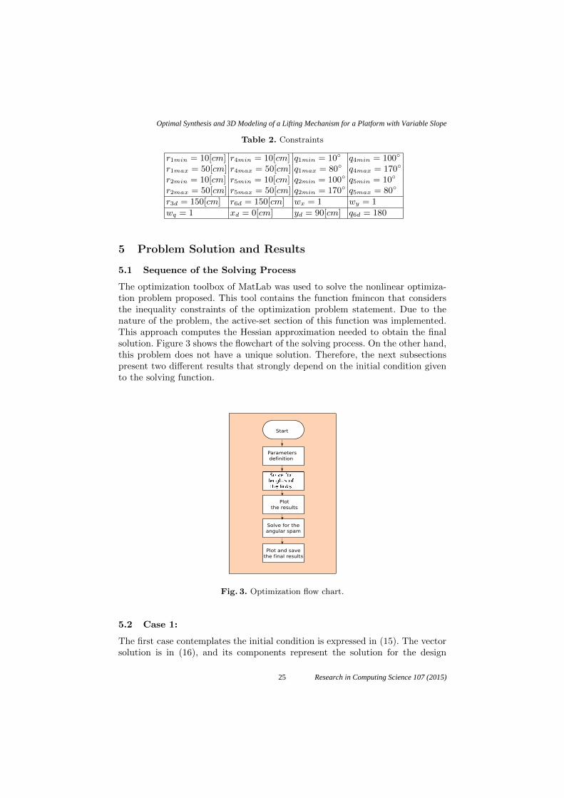
Table 2. Constraints
r1min = 10[cm] r4min = 10[cm] q1min = 10◦ q4min = 100◦
r1max = 50[cm] r4max = 50[cm] q1max = 80◦ q4max = 170◦
r2min = 10[cm] r5min = 10[cm] q2min = 100◦ q5min = 10◦
r2max = 50[cm] r5max = 50[cm] q2min = 170◦ q5max = 80◦
r3d = 150[cm] r6d = 150[cm] wx = 1 wy = 1
wq = 1 xd = 0[cm] yd = 90[cm] q6d = 180
5 Problem Solution and Results
5.1 Sequence of the Solving Process
The optimization toolbox of MatLab was used to solve the nonlinear optimiza-tion problem proposed. This tool contains the function fmincon that considersthe inequality constraints of the optimization problem statement. Due to thenature of the problem, the active-set section of this function was implemented.This approach computes the Hessian approximation needed to obtain the finalsolution. Figure 3 shows the flowchart of the solving process. On the other hand,this problem does not have a unique solution. Therefore, the next subsectionspresent two different results that strongly depend on the initial condition givento the solving function.
Parameters
definition
Start
Solve for the
angular spam
Plot and save
the final results
Plot
the results
Fig. 3. Optimization flow chart.
5.2 Case 1:
The first case contemplates the initial condition is expressed in (15). The vectorsolution is in (16), and its components represent the solution for the design
25
Optimal Synthesis and 3D Modeling of a Lifting Mechanism for a Platform with Variable Slope
Research in Computing Science 107 (2015)

problem. Figure 4 illustrates a view of the final configuration
X01 = [1 0 1 0 0 0 0 0 0 0 0 180◦]T (15)
X∗01 = [49.98 50 150 49.99 41.95 150 64.15◦
115.82◦ 0100.81◦ 77.1◦ 179.9◦]T (16)
Fig. 4. Configuration for the initial condition 1.
5.3 Case 2:
For this second case, it is proposed the initial condition expressed in (17). Thevector solution is in (18), and its components represent the solution for the designproblem. Figure 5 illustrates a view of this final configuration.
X02 = [50 50 150 50 50 150 50◦ 50◦ 0◦
50◦ 50◦ 180◦]T (17)
X∗02 = [46.74 46.77 150 48.89 44.04 150
74.23◦ 105.74◦ 0◦ 103.69◦ 74.74◦
179.98◦]T (18)
26
Eduardo Vázquez-Santacruz, Cuauhtémoc Morales-Cruz, Rogelio de Jesus Portillo-Velez, et al.
Research in Computing Science 107 (2015)
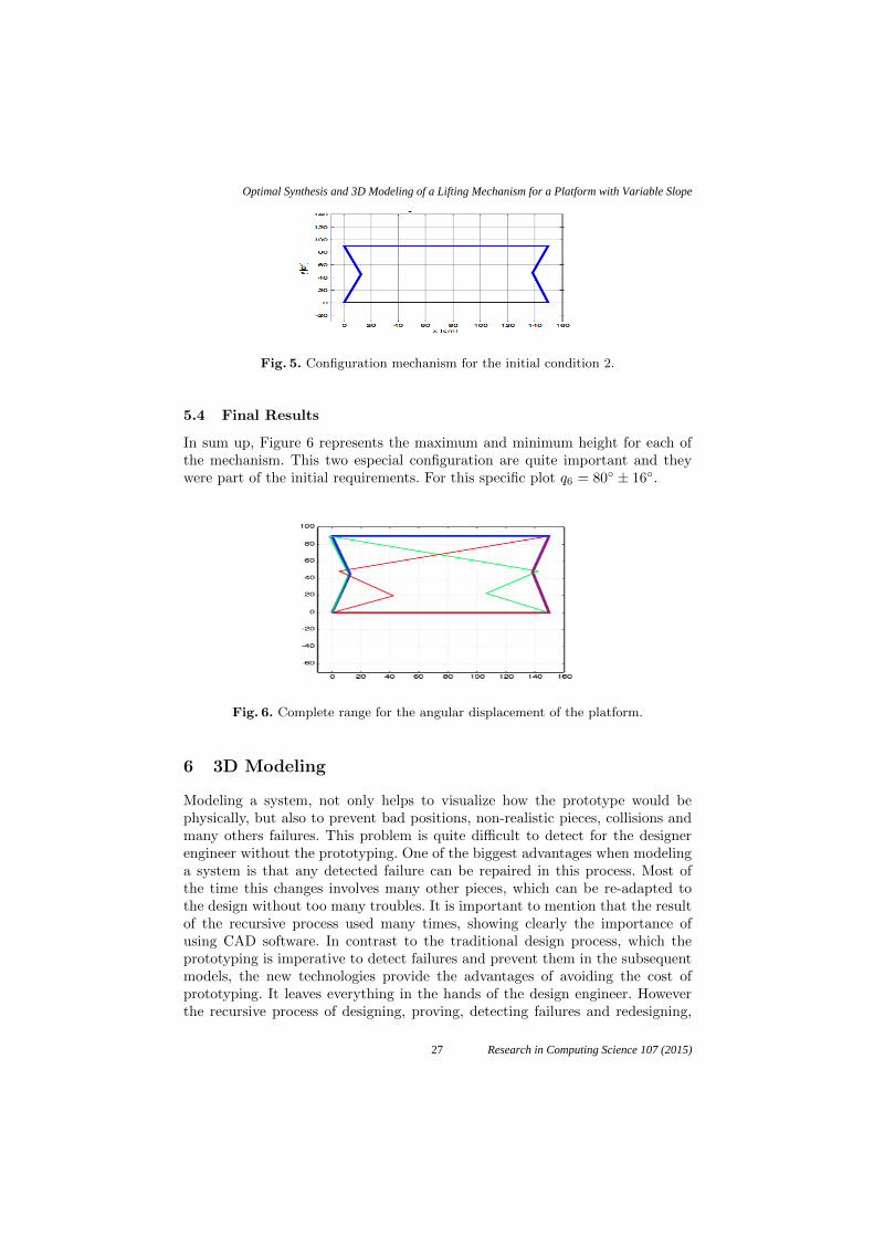
Fig. 5. Configuration mechanism for the initial condition 2.
5.4 Final Results
In sum up, Figure 6 represents the maximum and minimum height for each ofthe mechanism. This two especial configuration are quite important and theywere part of the initial requirements. For this specific plot q6 = 80◦ ± 16◦.
Fig. 6. Complete range for the angular displacement of the platform.
6 3D Modeling
Modeling a system, not only helps to visualize how the prototype would bephysically, but also to prevent bad positions, non-realistic pieces, collisions andmany others failures. This problem is quite difficult to detect for the designerengineer without the prototyping. One of the biggest advantages when modelinga system is that any detected failure can be repaired in this process. Most ofthe time this changes involves many other pieces, which can be re-adapted tothe design without too many troubles. It is important to mention that the resultof the recursive process used many times, showing clearly the importance ofusing CAD software. In contrast to the traditional design process, which theprototyping is imperative to detect failures and prevent them in the subsequentmodels, the new technologies provide the advantages of avoiding the cost ofprototyping. It leaves everything in the hands of the design engineer. Howeverthe recursive process of designing, proving, detecting failures and redesigning,
27
Optimal Synthesis and 3D Modeling of a Lifting Mechanism for a Platform with Variable Slope
Research in Computing Science 107 (2015)

must be kept. The lifting mechanism modeled in this work is composed of twosubsystems. Which provide not only the vertical motion of the surface but alsothe ability to change the slope of the plane. An isometric view of the entiresystem is shown in the Figure 7(a), as well as the location of the two subsystems,mentioned before.Finally Figure 7(b) shows the distribution of the load withpurple arrows. It contemplates the load that the system will be moving withduring its operation. However the details will not be covered in this document.
Mechanism 1
Mechanism 2
(a) (b)
Fig. 7. Physical and schematic description.
7 Conclusion
This paper presented the synthesis of a lifting mechanism as an optimizationproblem. The analysis of position was carried out and the requirements of thefinal system were set to guide the process. At the end a complete mechanismwas obtained and it is capable of moving according to the restrictions imposed.This work has shown how to take advantage of optimization in order to sim-plify the design process. Additionally, a 3D model of the lifting mechanismwas presented. It has been used 3D CAD software tools for its development.This work contributes, as an example, to the design process, which is currentlyemployed. Despite the traditional process, where most of the time it has to builda prototype, to prove the motion of the system, this work present an alternativemethodology with some advantages explained before.
References
1. Andhare, A., Onkar, A., Padole, P.: Design of bed for bedridden patients: Analysisand synthesis of mechanisms. In: 15th National Conference on Machines andMechanisms, Chennai, Tamilnadu, India. pp. 1–6 (2011)
28
Eduardo Vázquez-Santacruz, Cuauhtémoc Morales-Cruz, Rogelio de Jesus Portillo-Velez, et al.
Research in Computing Science 107 (2015)
2. Beltran-Herrera, A., Vazquez-Santacruz, E., Gamboa-Ziga, M.: Real-time classifi-cation of lying bodies by HOG descriptors. In: 6th Mexican Conference on PatternRecognition MCPR. pp. 211–220 (2014)
3. Ching-Hua, W., Ting-Chun, T., Shin-Chieh, H., Wan-Chun, C., Yen-Ming, C.,Kun-Tse, T., Chun-Went, Y., Kuo-YiI, C.: Hospital bed with auxiliary functions oflateral positioning and transferring for immobilized patients. In: The 33rd AnnualConference of the IEEE Industrial Electronics Society (IECON). pp. 2991–2995(2007)
4. Kap-Ho, S., Changmok, O., Tae-Yong, C., Ju-Jang, L.: Bed-type robotic system forthe bedridden. In: Proceedings of the 2005 IEEE/ASME International Conferenceon Advanced Intelligent Mechatronics, Monterey, California, USA. pp. 1170–1175(2005)
5. Kittipichai, R., Ariyarit, A.: The sizing optimization of hospital bed structurefor independently supporting left and or right leg using genetic algorithms. In:International Journal of Modeling and Optimization. vol. 11, pp. 122–188 (2011)
6. Mohammeda, M.N., Khrita, N.G., Abdelgneia, M.A., Abubakera, Es.and Muftaha,A., Omara, M.Z., Salleha, M.S.: A new design of multi-functional portable patientbed. In: Jurnal Teknologi (Sciences & Engineering). vol. 58, pp. 61–66 (2012)
7. Shih-Wei, P., Feng-Li, L., Li-Chen, F.: Mechanism design and mechatronic controlof a multifunctional test bed for bedridden healthcare. In: IEEE/ASME transac-tions on mechatronics. vol. 15, pp. 234–241 (2010)
8. Uicker, J., Pennock, G., Shigley, J.: Theory of Machines and Mechanisms. McGraw-Hill series in mechanical engineering, Oxford University Press (2003)
9. Vazquez-Santacruz, E., Gamboa-Zuniga, M.: A diagnosis methodology for assistivetechnology development. In: 10th International Conference on Electrical Engineer-ing, Computing Science and Automatic Control (CCE). pp. 163–169 (2013)
10. Wang, Y., Butner, S., Darzi, A.: The developing market for medical robotics.Proceedings of the IEEE 9(94), 1763–1771 (2006)
11. Zwicky, F.: Morphologie and Policy Analysis. 16th EURO Conference on Opera-tional Analysis, Brussels (1998)
29
Optimal Synthesis and 3D Modeling of a Lifting Mechanism for a Platform with Variable Slope
Research in Computing Science 107 (2015)