optimal network reconfiguration in distribution system...
TRANSCRIPT

24th International Conference on Electricity Distribution Glasgow, 12-15 June 2017
Paper 1007
CIRED 2017 1/5
OPTIMAL NETWORK RECONFIGURATION IN DISTRIBUTION SYSTEM FOR LOSS
REDUCTION AND VOLTAGE PROFILE IMPROVEMENT USING HYBRID ALGORITHM
OF PSO AND ACO
Mohammad Amin Heidari
Shiraz Electrical Distribution Company (SHEDC)-Iran
ABSTRACT
Considering time varying nature of load in conventional
distribution system, network reconfiguration is
combinatorial complex optimization problem. In this
paper, a hybrid configuration of particle swarm
optimization (PSO) method with ant colony optimization
(ACO) algorithm called hybrid PSO–ACO algorithm is
presented for optimal network reconfiguration in
distribution network in presence of distributed generation
(DG) resources. The objectives consist of minimizing
power losses and improving the voltage profile. MATLAB
based simulation conducted on 33-bus IEEE test feeder to
verify the effectiveness of proposed method. Results
demonstrate accuracy and efficiency of PSO–ACO
algorithm.
INTRODUCTION
Network reconfiguration is the key to realizing a reliable, flexible and active distribution system. Rapid load demand growth, penetration of distributed generation (DG) resources and industrialization made distribution system reconfiguration (DSR) essential. DSR is the act of opening and closing the switching devices of power systems to reach a topology that optimizes the desired objectives [1]. Variety of objectives such as power losses and total interruptions [2], Load Balancing [3], Voltage Profile Improvement [4], Service Restoration [5], reliability and power quality improvement [6] has been considered to solve DSR problem. A rigorous classification of the DSR solution methods is difficult. DSR solving methods can be generalized in three major classifications: Heuristic Methods, Conventional Programming and Dynamic Programming [7]. In this paper PSO-ACO algorithms -a nature-inspired methodology- developed to address complex DSR problem that is difficult to solve by traditional approaches. Combination of two optimization methods (PSO and ACO) will cover shortcomings of each individual and provide more flexibility in choosing the best configuration. Since conventional load flow method failed to converge in solving the load flow problem in an unbalanced three phase distribution system, a novel load flow method for distribution system developed and introduced. The remainder of this paper is organized as follows: next section explains the optimal DSR problem formulation. Then the necessary background and fundamentals of the PSO and ACO algorithms and the implementation of the
proposed hybrid ACO–ABC algorithm are described. Load flow method used for this paper introduced after that. Finally proposed method is applied on 33-bus IEEE test feeder and numerical results discussed.
PROBLEM FORMULATION
The main goal of optimal DSR is to determine the best
configuration of distribution network to minimize
specific objective functions. In this section the objective
functions and constraints are explained.
Objective functions
Minimization of power losses
Reducing the total electrical energy losses of distribution
network is an important goal of network reconfiguration,
active power loss of each branch can be formulated as
follows:
2
22
1,
)()1,(
i
iiiiLOSS
V
QPRiiP
(1)
Where i is the bus number, 1, iiR represent the branch
resistance and iV , iP and iQ are bus voltage, active and
reactive power respectively. Total power loss of system
could be calculated from equation (2).
N
i
LOSS iiPf1
1 )1,( (2)
Finally the first objective function described as:
)min()( 11 fXF (3)
Minimizing the deviation of the bus voltage
Minimizing the deviation of bus voltage is selected as the
second objective function for the DSR. Bus voltage is
one the most significant security and power quality
indices. This objective function can be described as
follows:
N
i Rating
iRating
V
VVf
1
2 (4)
)min()( 22 fXF (5)

24th International Conference on Electricity Distribution Glasgow, 12-15 June 2017
Paper 1007
CIRED 2017 2/5
Where N is the total number of the buses. iV is the real
voltage of the thi bus and RatingV is the nominal voltage.
Constraint
In the optimal reconfiguration of distribution network, the
systems need to meet certain constraints. They can be
listed and mathematically expressed in the following
subsections.
Voltage constraint
According to the ANSI C84.1 voltage magnitudes should
be maintained within 5% of the nominal value. In this
paper the ±5% limit is considered as “strict” and
“excellent”, and ±10% limit is considered as “loose” and
“fair”.
UUU
UUU
ii
iii
1.19.0
maxmin
(6)
Where iU , min
iU and max
iU are the magnitude, allowable
lower and higher values of voltage at bus i.
Current constraint
Current at each branch must be less than or equal to its
maximum capacity. This constraint can be described as: max
ijij II (7)
Where max
ijI and ijI are maximum current and current
of branch between nodes i and j.
System Structure Constraint
Because of the easy protection schemes implementation
of radial structure, distribution networks should remain
radial before and after reconfiguration. To insure meeting
this constraint:
KNSM
K
K 1
(8)
Where M is the total number of branches in the system, N
is the total number of buses. Load should meet
continuously:
dNArank )( (9)
A is the node branch incidence matrix which is described
in [8] and d is the total number of slack buses. At least in
each loop there is one open branch so:
11
K
M
K
i MSK
(10)
Where, KM is the amount of branches in the thk loop
[9].
PROPOSED HYBRID ALGORITHM
Particle Swarm Optimization
A particle swarm optimization (PSO) algorithm is a kind
of Swarm Intelligence (SI) technology, which was
initially proposed by Eberhart and Kennedy in 1995[9].
Inspired by birds flocking, the core concept of
PSO is to find out the optima or sub-optima of an
objective function through the co-operation and
information sharing among particles. Since PSO is
efficient, simple and robust, it has been widely used in
multi-objective optimization.
The classic PSO starts with a population of random
solutions „„particles‟‟ in a D-dimension space. The ith
particle is represented by Xi = (xi1,xi2, . . . ,xiD). Each
particle keeps track of its coordinates in hyperspace,
which are associated with the fittest solution it has
achieved so far. The value of the fitness for particle i
( bestp ) is also stored as Pi = (pi1, pi2, . . . ,piD). The global
version of the PSO keeps track of the overall best value
( bestg ), and its location, obtained thus far by any particle
in the population. The PSO consists of, at each step,
changing the velocity of each particle toward its pbest
and gbest according to Eq. (11). The velocity of particle i
is represented as Vi= (vi1, vi2. . . viD). Acceleration is
weighted by a random term, with separate random
numbers being generated for acceleration toward pbest
and gbest. The position of the ith particle is then updated
according to Eq. (12) [10]:
)()( 2211
1 t
d
t
d
t
id
t
id
t
id
t
id xgrcxprcvv
(11)
11
t
id
t
id
t
id vxx (12)
Where ∀ i ∈ NN, NN = {1, 2,... N}, N is the size of the
swarm; d is the index of the co-ordinate being updated; c1
and c2 are positive constants, called acceleration
constants; r1 and r2 represent random numbers, following
the uniform distribution over [0, 1].
Ant colony optimization
Ant colony optimization is one of the population based
met heuristic techniques based on the foraging behaviour
of real ants. They forage for food and establish the
shortest paths from their nest to the food source. When
the ants move along the paths, they lay a chemical
substance called pheromone as they travel. In turn,
shorter paths will have the higher rate of pheromone
trails. Each ant makes decisions by using pheromone
trails as a communication mechanism. All pheromone
trails are eventually reduced by an evaporation rate. On
the other side, a process of evaporation presents the
exploration and prevents stalling in a local minimum.
However, the pheromone values are updated at the end of
each iteration [12].

24th International Conference on Electricity Distribution Glasgow, 12-15 June 2017
Paper 1007
CIRED 2017 3/5
otherwise 0
, )(
)(
))((
k
i
s
isis
ijij
ij
Nsjt
t
tkp
(13)
Where )(kpij is the probability which ant k chooses to
move from node i to node j. This decision depends on the
pheromone level and heuristic information. While k
iN
is the set of feasible neighbourhoods that have not yet
been visited by ant k, ij is heuristic function,
ij is
the amount of pheromone on edge i and j, and and
are the parameters which determine the relative
importance of pheromone concentration and heuristic
information. The pheromone update can be formed as
follows:
ijijij (14)
otherwise 0
l L
Q k
ij
kij (15)
The evaporation update is given by:
ij
k
ij
k
ij tt )()1()(1 (16)
Where is the constant factor reduction of all
pheromones, the above optimization process is
terminated after a certain amount of iteration.
PSO-ACO algorithm
Although PSO and ACO algorithms have been developed
for various optimization tasks, it does not seem that either
of the current algorithms is ideally suited for all
problems. As an instant, in many cases if the global best
and local best positions are equal to the particle‟s position
over a number of iterations in PSO the process of
optimization may trapped in local optima.
In this paper ACO is incorporated in basic PSO to
improve exploration power of algorithm to examine
much more solutions according to proposed method in
[12].In basic PSO global best position -which play
important role in the guidance of particles- is unique for
every particle. If the Gbest value does not change after
some iteration, other particles gradually get close to the
Gbest position and The ability of the best agent to search
local area is also reduced. In PSO-ACO algorithm Gbest
is selected by ACO best path selection methodology for
each particle.
LOAD FLOW METHOD
Generally, distribution networks are radial and the R/X
ratio is very high compared to a transmission system.
This makes the distribution system ill-conditioned. That
is why the conventional load flow method such as
Newton-Raphson (NR), the Fast Decoupled Load Flow
(FDLF) method and their modification are not suitable
for solving the load flow problem in distribution system.
The main idea of load flow method is extracted from
what is mentioned in [13] and modified. This load flow
method is used to calculate the voltage at each bus and
total real and reactive power losses. Consider a single line diagram of two buses of a radial
distribution system as shown in Figure (1) , the number
of branches nb and the number of buses t are related
through t = nb+1.
Figure (1): Single line diagram of two buses of a distribution
system
Where R and X are resistance and reactance of the
branch. PLk and QLk are the active and reactive powers of
node k. ILi is the current flowing in the line. Subscript „L‟
in PLS and QLS refers to the load connected at Sth
bus.
Initially, a flat voltage (1 p.u) of all the nodes is
assumed and load currents and charging currents of all
the loads are computed using equations. (17) and (18). The load current of node k is:
( ) ( )( )
*( )
Lk LkLk
P k jQ kI k
V k
(17)
for k = 2, 3,……. nb
Where PLk (k) and QLk (k) are active and reactive power
of load connected to node k, respectively. The charging
current can be stated as:
0( ) ( )* ( )CkI k y k V k (18)
k = 2, 3…… nb
Here shunt admittance yo is considered as small. Branch Current I(n) is equal to the sum of the load
currents of all the nodes beyond that branch n plus the
sum of the charging currents of all the nodes beyond that
branch n i.e.,
1 1
( ) ( ) ( )nb nb
Lk Ck
k n i n
I n I k I k
(19)
Where branch impedance is Z = R + j X. Therefore, if it
is possible to identify the nodes beyond all the branches,
it is possible to compute all the branch currents. A
generalized equation of receiving-end voltage, sending-
end voltage, branch current and branch impedance is:

24th International Conference on Electricity Distribution Glasgow, 12-15 June 2017
Paper 1007
CIRED 2017 4/5
)(*)()()( 12 iZiIaVaV (20)
Where i is the branch number and 1a and 2a are:
)(1 iREa
)(2 iSEa (21)
Where )(iRE is the receiving end and )(iSE is
the sending end of branch i . The real and reactive power
loss of branch i are given as: 2
Re )(*)()( iIiRiL al
2
Re )(*)()( iIiXiL active (22)
Where )(Re iL al and )(Re iL active are the active and
reactive power losses at branch i.
At first identification of the nodes beyond all the
branches is realized through an algorithm. Figure (2)
shows the Pseudo codes of proposed load flow algorithm.
Figure (2): Pseudo codes of proposed load flow algorithm.
SOLUTION OF PSO-ACO FOR DSR
This section presents the proposed hybrid algorithm
based on the combination of PSO and ACO sets for multi
objective distribution system reconfiguration and DG
installation problems for real power loss minimization
and voltage profile improvement. The PSO-ACO
algorithm applied on tested on a 33-bus radial distribution
network that is shown in Figure (4) and whose
information is available in [15]. It contains 32
sectionalizing switches and five tie lines. The decision
making variables vector encoding strategy adopted in this
paper is shown in figure (3).
Figure (3): decision making variables vector
Where is open switches corresponding to tie switches
and is the size of DG units which limited into 3 in
this paper. To verify the effectiveness of proposed
method and providing comparing possibility candidate
bus locations considered for DG installations in this paper
are identical to what is done in [14] so DG units installed
in buses 32, 31 and 33.
Figure (4): IEEE 33-bus test feeder [15].
RESULTS AND DISCUSSION
Two test scenarios are conducted on mentioned test
feeder to verify the effectiveness of PSO-ACO algorithm:
Scenario I: system is under nominal load and
reconfigured by the available sectionalizing
and tie switches without installation of DG units.
Scenario II: system is under nominal load
reconfigured by the available sectionalizing
and tie switches and DG units installed in candidate
buses.
The load flow before reconfiguration under nominal load
shows 202.67 KW power losses and 0.91 P.U minimum
node voltage. Results of first test scenario under nominal
load are shown and compared with Harmony Search
Algorithm (HSA) in table (1). The solutions obtained by
PSO-ACO demonstrate better voltage profile and 35.94
percent reduction of power losses. The trend of finding
the best solution is revealed in figure (5).
Table (1): Simulation results for scenario I.
Method Item
HSA[14] PSO-ACO
7,14,9,32,37 7,9,14,25,32 Switches opened
138.06 129.83 Power loss (KW)
0.9342 0.9388 Min. node voltage(P.U)
…
Step 1 : Read the line and load data. Step 2 : Determine the nodes beyond each
branch and their total number. Step 3 : Initialize the voltage of all nodes to 1p.u
and phase angle to zero. Step 4 : Find all load currents and charging
currents of each nodes using equation. (17) and equation (18) by using these branch currents are determined given in equation (19)
Step 5
: Calculate the voltages and phase angles at each node by using equation (20).
Step 6 : If the voltage at each node for two successive iteration is within a certain tolerance (10-4p.u) the solution is reached go to step 8 else, repeat step 5 to 7 until convergence is reached.
Step 7 : Read the results
Step 8 : End
24th International Conference on Electricity Distribution Glasgow, 12-15 June 2017
Paper 1007
CIRED 2017 5/5
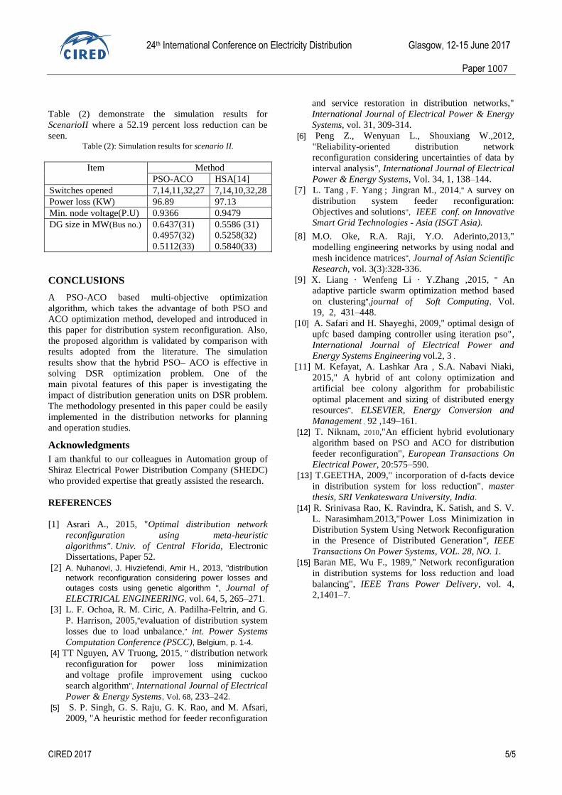
Table (2) demonstrate the simulation results for
ScenarioII where a 52.19 percent loss reduction can be
seen. Table (2): Simulation results for scenario II.
Method Item
HSA[14] PSO-ACO
7,14,10,32,28 7,14,11,32,27 Switches opened
97.13 96.89 Power loss (KW)
0.9479 0.9366 Min. node voltage(P.U)
0.5586 (31)
0.5258(32)
0.5840(33)
0.6437(31)
0.4957(32)
0.5112(33)
DG size in MW(Bus no.)
CONCLUSIONS
A PSO-ACO based multi-objective optimization
algorithm, which takes the advantage of both PSO and
ACO optimization method, developed and introduced in
this paper for distribution system reconfiguration. Also,
the proposed algorithm is validated by comparison with
results adopted from the literature. The simulation
results show that the hybrid PSO– ACO is effective in
solving DSR optimization problem. One of the
main pivotal features of this paper is investigating the
impact of distribution generation units on DSR problem.
The methodology presented in this paper could be easily
implemented in the distribution networks for planning
and operation studies.
Acknowledgments
I am thankful to our colleagues in Automation group of
Shiraz Electrical Power Distribution Company (SHEDC)
who provided expertise that greatly assisted the research.
REFERENCES
[1] Asrari A., 2015, "Optimal distribution network
reconfiguration using meta-heuristic
algorithms". Univ. of Central Florida, Electronic
Dissertations, Paper 52.
[2] A. Nuhanovi, J. Hivziefendi, Amir H., 2013, "distribution
network reconfiguration considering power losses and
outages costs using genetic algorithm ", Journal of
ELECTRICAL ENGINEERING, vol. 64, 5, 265–271.
[3] L. F. Ochoa, R. M. Ciric, A. Padilha-Feltrin, and G.
P. Harrison, 2005,"evaluation of distribution system
losses due to load unbalance," int. Power Systems
Computation Conference (PSCC), Belgium, p. 1-4.
[4] TT Nguyen, AV Truong, 2015, " distribution network
reconfiguration for power loss minimization
and voltage profile improvement using cuckoo
search algorithm", International Journal of Electrical
Power & Energy Systems, Vol. 68, 233–242.
[5] S. P. Singh, G. S. Raju, G. K. Rao, and M. Afsari,
2009, "A heuristic method for feeder reconfiguration
and service restoration in distribution networks,"
International Journal of Electrical Power & Energy
Systems, vol. 31, 309-314.
[6] Peng Z., Wenyuan L., Shouxiang W.,2012,
"Reliability-oriented distribution network
reconfiguration considering uncertainties of data by
interval analysis", International Journal of Electrical
Power & Energy Systems, Vol. 34, 1, 138–144.
[7] L. Tang , F. Yang ; Jingran M., 2014," A survey on
distribution system feeder reconfiguration:
Objectives and solutions", IEEE conf. on Innovative
Smart Grid Technologies - Asia (ISGT Asia).
[8] M.O. Oke, R.A. Raji, Y.O. Aderinto,2013,"
modelling engineering networks by using nodal and
mesh incidence matrices", Journal of Asian Scientific
Research, vol. 3(3):328-336.
[9] X. Liang · Wenfeng Li · Y.Zhang ,2015, " An
adaptive particle swarm optimization method based
on clustering",journal of Soft Computing, Vol.
19, 2, 431–448.
[10] A. Safari and H. Shayeghi, 2009," optimal design of
upfc based damping controller using iteration pso",
International Journal of Electrical Power and
Energy Systems Engineering vol.2, 3 .
[11] M. Kefayat, A. Lashkar Ara , S.A. Nabavi Niaki,
2015," A hybrid of ant colony optimization and
artificial bee colony algorithm for probabilistic
optimal placement and sizing of distributed energy
resources", ELSEVIER, Energy Conversion and
Management , 92 ,149–161.
[12] T. Niknam, 2010,"An efficient hybrid evolutionary
algorithm based on PSO and ACO for distribution
feeder reconfiguration", European Transactions On
Electrical Power, 20:575–590.
[13] T.GEETHA, 2009," incorporation of d-facts device
in distribution system for loss reduction", master
thesis, SRI Venkateswara University, India.
[14] R. Srinivasa Rao, K. Ravindra, K. Satish, and S. V.
L. Narasimham,2013,"Power Loss Minimization in
Distribution System Using Network Reconfiguration
in the Presence of Distributed Generation", IEEE
Transactions On Power Systems, VOL. 28, NO. 1.
[15] Baran ME, Wu F., 1989," Network reconfiguration
in distribution systems for loss reduction and load
balancing", IEEE Trans Power Delivery, vol. 4,
2,1401–7.