optimal design of symmetric angle-ply laminates subject to nonuniform buckling loads and in-plane...
TRANSCRIPT

ELSEVIER
Thin-Walh, d Structures Vol. 26, No. I, pp. 45 60, 1996 Copyright ( 1996 Elsevier Science Ltd
Printed in Great Britain. All rights reserved 0263-8231/96 $15.00
S 0 2 6 3 - 8 2 3 I ( 9 6 ) 0 0 0 0 2 - X
Optimal Design of Symmetric Angle-Ply Laminates Subject to Nonuniform Buckling Loads and In-Plane
Restraints
M. Walker," S. Adali b & V. E. Verijenko b
"Center for Engineering Research, Technikon Natal, Durban, South Africa ~'Department of Mechanical Engineering, University of Natal, Durban, South Africa
(Received 29 April 1994; revised version received 25 October 1995; received for publication 3 January 1995)
A B S T R A C T
Optimal buckling designs of symmetrically laminated rectangular plates under in-plane uniaxial loads" which have a nonuniform distribution along the edges are presented. In particular, point loads, partial uniJorm loads and nonuniform loads" are considered in addition to uniform O' distributed in- plane loads" which provide the benchmark solutions. Poisson's effect is" taken into account when in-plane restraints are present along the unloaded edges. Restraints give rise to in-plane loads" at unloaded edges which lead to biaxial loading, and may cause premature instability. The laminate beha- viour with respect to fiber orientation changes significantly in the presence of Poisson's eJfi, ct as compared to that o/'a laminate where this" ~Jfect is neglected. This change in behaviour has significant implications Jor design optimisation as the optimal values of design variables with or without restraints differ substantially. In the present study, the design objective is" the maximisation of the uniaxial buckling load by optimally determining the fiber orientations. The )qnite element method, coupled with an optimi- sation routine, is employed in analysing and optimising the laminates. Numerical results are given for a number of boundary conditions and fi)r uniJormly and non-uniformly distributed buckling loads. Copyright :~'~ 1996 Elsevier Science Ltd.
1 I N T R O D U C T I O N
L a m i n a t e d compos i t es have seen increasing use as s t ruc tura l mater ia ls due main ly to their low weight- to-s t i f fness and s t rength ratios. An advan tage
45

46 M. Walker, S. Adali, V. E. Ver{fl'nko
of composite materials over conventional ones is the possibility of tailor- ing their properties to the specific requirements of a given application. The tailoring is mostly achieved by optimising the mechanical properties, thereby increasing the load carrying capacity of the structure. The present study is concerned with the design optimisation of laminated plates under non-uniform buckling loads taking the effect of Poisson's ratio into account, and using the fiber orientation as the design variable.
Poisson's effect manifests itself as in-plane loads if the unloaded edges are restrained from translating freely. This in turn transforms a uniaxial buckling problem into a biaxial one and causes a reduction in the buckling load, as compared to the classic case. Moreover, the optimal values of design variables change as compared to the classic case. In the classic uniaxial buckling analysis of laminated rectangular plates, the unloaded edges (3' = 0 and y = b, Fig. 1 ) are assumed to be free from restraint in the plane of the plate. ~ 4 However, this assumption leads to incorrect buckling loads in those cases where these edges are, in fact, restrained from trans- lation due to the presence of obstacles. In the absence of in-plane restraints, a compressive force N,0 in the x-direction causes a constant transverse strain ~:,. in the y direction due to Poisson's effect, and the pre-
Z Y
(9 Fig. !. Geometry and loading of the laminated plate.
Optimal design o[ o,mmetric angle-ply laminates 47
buckling stage can be described by specifying N,-= N,-0 (applied compression), and Nv = N~.0 = o. In the presence of in-plane restraints, N,. is no longer zero, and has to be computed.
In many practical situations, transverse movement of unloaded edges is restricted by adjacent panels, supports or stiffeners, inducing a transverse in-plane compressive force. In these cases, the buckling of uniaxially compressed rectangular plates is affected by the so-called Poisson Plate Instability phenomenon. As illustrated in the present paper, an optimal design for maximum buckling load based on the classical analysis becomes irrelevant and leads to totally erroneous results in the presence of in-plane restraints. Moreover, it is often the case that the buckling loads are not uniformly distributed along the edges. An approximation of nonuniform loads by uniform ones again leads to inaccurate buckling loads and non- optimal ply angles.
Buckling of orthotropic plates subject to edge restraints was studied by Harris 5 who illustrated the destabilizing effect of restraints for simply supported plates. Sherbourne & Pandey 6 studied the behaviour of such plates by approximating the displacement using a series of orthogonal polynomials, and computed the buckling load using the Rayleigh-Ritz method. From their results, it is evident that the variation of the buckling loads with respect to the ply angle is similar to that given by Obraztsov & Vasil'ev. 7 Buckling of composite laminates subject to linearly varying uniaxial and biaxial loads was studied in Refs 8 10. The effect of Poisson's ratio on the optimal design of laminates under uniform buckling loads has been studied in Ref. 11.
The present study deals with the optimal design of uniaxially loaded symmetrically laminated rectangular plates subject to in-plane restraints along the unloaded edges taking the ply angle as the design variable to maximise the buckling load. The results are obtained for uniformly (Fig. i) and non-uniformly distributed in-plane loads. In particular, point loads (Fig. 2(a)), partial uniform loads (Fig. 2(b)) and nonuni- form loads (Fig. 2(c)) are considered in addition to a full uniform load. Taken into account also are the effects of bending-twisting coupling, as well as various combinations of free, simply supported and clamped boundary conditions. These effects rule out the possibility of an analytical solution and thus the finite element method is used to analyse the problem and to determine the buckling loads. The FEM formulation employed in the analysis is based on Mindlin type theory for laminated composite plates, and is used in conjunction with an optimisation routine to compute the optimal fiber orientations. Opti- mal designs are compared with those obtained for plates without in- plane restraints.

48 M. Walker, S. Adali, V. E. Ver(jenko
Z ¥
N×
,X
b Nx
/
/ / /
i"
Fig. 2. Nonuniformly distributed buckling loads. (a) Concentrated load; (b) partial uniform load: (c) nonuniformly distributed load. (Note that x - 0.0323.) Continued opposite.
2 BASIC E Q U A T I O N S
Consider a symmetrically laminated rectangular plate of length a with width b (Fig. 1). The plate is constructed of equal thickness or thotropic layers with fiber angles Ok and k -- 1 , 2 , . . . , K where K denotes the total number of layers. The coordinate system xyz is located in the mid-plane, and the plate is subjected to uniaxiat compression N,- in the x direction. The unloaded edges y - 0, y - a are restrained from translating in the y direction giving rise to Poisson's effect, and resulting in compressive forces in this direction. This phenomena leads to a loss of stability under biaxial compressive forces even though the applied load is uniaxial.
In the present study, a first-order shear deformable theory is employed to analyse the problem and the following displacement field is assumed
u - Uo(X,y) + z O , ( x , y )
v -- Vo(x,y) + zO~,(x,y) (1)
w = w ( x , y )

Optimal design O[',Evmmetric angle-pO' laminates 49
Nx/
¥
3 -~ , x
, ×
(b)
Nx/- \
Z y
F'
b //,Nx
(C)
Fig. 2. Continued.
50 M. Walker, S. Adali, V. E. VeHjenko
where u0, v0 and w0 are the displacements of the reference surface in the x, y and z directions, respectively, and 0,., ~9,. are the rotations of the trans- verse normal about the x and y axes.
The in-plane strain components can be written as a sum of the exten- sional and flexural parts and they are given as
where
=
and
{,-,,} = ,,o,,. j , o, . . (31
Uo.,. + Vo, , . / 0,. + 0,.
Here, a subscript after the comma denotes differentiation with respect to the variable following the comma.
The transverse shear strains are obtained from
?',._- w0.., + 6,.
The equations for the in-plane stresses of the kth layer under a plane stress state may be written as
and similarly for the transverse shear stresses as
(Tvz) (~_44 ~:5"~ ( )'v: ) ~[C](k){7 } (6) "C,.: (k) \Q45 Q s J ( k ) )":
where c~ is a shear correction factor, 12 and Q0 are the transformed stiff- nesses. Equations (5) and (6) may be written in compact form as
o-k = Qt.~: (7)
where Qk refers to the full matrix with elements (Q~)k, and ak and r, represent in-plane and transverse stresses and strains, respectively. The resulting shear forces and moments acting on the plate are obtained by integrating the stresses through the laminate thickness,
Opt imal design o f symmetr ic angle-ply laminates 51
h/2 {v} r = (G, G) =
a-~/2 (8)
[ ~/2 {M} r = (Mx, Mr, Mx.r) = (ax, ay, axy)Z, dz.
a h/2
The relations between V and M, and the strains are given by
{V} = [S]{7}, {M} = [D]{9} (9)
where the stiffness matrices [S] and [D] are computed from
K j hA
[S] = c~ Z [C](~) dz k = 1 h~ ,
(10) K i lh
[DI = ~ [ Q ] ( k ) Z 2 d z . k = l .Ih~ ,
From the condition that the potential energy of the plate is stationary at equilibrium, and neglecting the pre-buckling effects, the equations governing the biaxial buckling of the shear deformable laminate are obtained as
Mx,xx + 2Mx,,,x.,, + M~,,y:, + N~w x,- + N v w ,,), = 0
Mx,x + Mxy,.,, - V~ = 0 (11 )
M~,y + M~y,x - V~ = 0
where N~ and N,' are the pre-buckling stress components which are shown in Figs 1 and 2. It is noted that Nx is the applied compressive load and N,, arises as a result of Poisson's effect in the presence of in-plane restraints. As no simplifications are assumed on the elements of the [D] matrix, eqns (11) include the bendin~twisting coupling as exhibited by virtue of Dr6 and D26 being non-zero.
3 FINITE ELEMENT FORMULATION
We now consider the finite element formulation of the problem. Let the region S of the plate be divided into n sub-regions S~ (St E S; r = 1 ,2 , . . . , n ) such that
//
H(u) = Z IIs' (u) (12) r - . J

5 2 M. Walker, S. A&di, V. E. Ver(jenko
where II and II s' are potential energies of the plate and the element, respectively, and u is the displacement vector. Using the same shape functions associated with node i (i 1,2 . . . . . n), Si(x, y), for interpolating the variables in each element, we can write
u £ S,(x,y)ui (13) i = 1
where l/i is the value of the displacement vector corresponding to node i, and is given by
" vl/i, '"I/', r ' ¢ ~ r ) ' (14)
The static buckling problem reduces to a generalised eigenvalue problem of the conventional form,
([/,;] + 0 (15)
where [K] is the stiffness matrix and [Ko] is the initial stress matrix. The lowest eigenvalue of the homogeneous system (15) yields the buckling load.
4 OPTIMAL DESIGN PROBLEM
The objective of the design problem is to maximise the buckling load N,. for a given laminate thickness/7 by optimally determining the fiber orien- tations given by 0a-=( 1) a~ tO for K<~ K/2 and Ok = ( - 1 ) ~ 0 for k >1 K/2 + 1. The buckling load N~(O) is given by
N.,.(0) = minm,, [N,,,,,(m, n, 0)] (16)
where N,,,, is the buckling load corresponding to the half-wave numbers m and n in the x and y directions, respectively. The design objective is to maximise N,(0) with respect to 0,
A Nm~x = max [N,(O)], 0 '~ <~ 0 <~ 9 0 (17)
0
where N,(0) is determined from the finite element solution of the eigenvalue problem given by eqn (16). The optimisation procedure involves the stages of evaluating the buckling load N~(O) and improving the fiber orientation to maximise N,.. Thus, the computational solution consists of successive stages of analysis and optimisation until a convergence is obtained and the optimal angle 0 o p t is determined within a specified accuracy. In the optimi- sation stage, the Golden S e c t i o n 13 method is employed.

Optimal design of symmetric angle-ply laminates 53
5 N U M E R I C A L RESULTS A N D DISCUSSION
The finite element formulation described in the previous section was veri- fied as described in an earlier paper. 4 For square plates, 256 square elements are used for meshing purposes, and for plates of aspect ratios other than unity, a proportional number of elements are used.
Numerical results are given for a T300/5208 graphite/epoxy material, with El = 181GPa, E2 = 10-3GPa, G12 = 7-17GPa and •12 = 0.28. The plate thickness to length ratio is specified as h/b = 0.01. The plate is constructed of four equal thickness layers with 01 = -02 = -03 = 04 = 0. The unloaded edges 1 and 3 are restrained from translation in the y direction. As mentioned previously, these restraints give rise to Poisson's effect when edges 2 and 4 undergo uniaxial compression (Figs 1 and 2). t
The results presented are obtained for plates with aspect ratios varying from 0.5 to 2. The non-dimensionalised buckling parameter Nb is defined a s
Nx b2 Nh -- (18) h3Eo
where Nx is the dimensional critical buckling load, and E0 is a reference value having the dimension of Young's modulus and is taken as E0 = 1 GPa.
First, comparat ive results are given for various loads for laminates with and without in-plane restraints. Tables 1-4 show the values of the optimal ply angles and the corresponding maximum buckling loads for simply supported laminates where the subscripts 'c' and 'p' denote the classical (Poisson's effect neglected) and the present (Poisson's effect included) cases, respectively. It is observed that as the aspect ratio r increases, so too does the discrepancy between the classical and present results. This
p c phenomenon can be clearly seen by checking the ratio Nmax/Nma x which drops to less than half as r reaches 2. The optimal ply angles also show
£ distinct differences. It is observed t h a t 0Popt is 10--20 ° less t h a n 0op t for r ~> 1 and this difference becomes larger for r = 0.5 and 0.75. Another interesting fact is that N~a x fluctuates as r increases while P N m a x decreases steadily. This is due to the biaxial nature of buckling loads in the presence of in-plane restraints. It is seen that the maximum buckling loads are the lowest for point loads and highest for uniformly distributed loads. In fact the buckling loads increase as the compressive forces become more uniformly distributed.
Next, the effect of boundary conditions is studied by considering five
tNote. in Fig. 2(c), x is t a k e n such t h a t the to ta l l oad is un i ta ry .

54 M. Walker, S. Adali, V. E. Ver(]enko
T A B L E 1 Optimisation Results for Laminates Under a Point In-Plane Load (Fig. 2(a))
) t t ~ p p p c r { opt Nh(Oopt) 0 P p t Nh(Oopt) N a / N h
0.50 28.6' 212.8 26.W 205.6 0-97 0.75 54.4 ~ 210.0 38.9 : 146. l 0-70 1-00 46-0 ~ 209-4 38-9' 129.8 0.62 1-25 42-0' 202-7 36-6' l 17.9 0.58 1-50 44-6' 198.6 35-1 ' 108.4 0.55 1.75 48-5 193-7 33-4 100.6 0.52 2-00 47 .7 189.5 32-2" 94-7 0.50
T A B L E 2 Optimisation Results for Laminates Under a Uniformly Distributed Partial In-Plane Load
(Fig. 2(b))
,. , ), ~P P p NP/N• r 0 opt N/, ( ~ opt ) ( opt N ~ (0,,p~)
0.50 0 324.1 0 '~ 323.0 0.99 0.75 53.4 259-2 0" 165.0 0-64 1.00 47 .5 228.3 36.7" 137.6 0.60 1.25 39 .6 222.5 35.3' 123-1 0.55 1.50 43 .4 214.2 33.6 ° 112-2 0.52 1.75 48.& 213-8 32.0" 103-5 0.48 2.00 47.5' 211-3 30.5" 97-1 0.46
T A B L E 3 Optimisation Results for Laminates Under a Nonuniformly Distributed Partial In-Plane
Load (Fig. 2(c))
< N t , / N h r 0 o,,,t Ni;(0;pt ) 0~pt Np (0Ppt) ,,, c
0.50 0 ' 471-9 0 ' 470.3 0.99 0.75 41-0 < 271-9 0 ' 227-7 0.84 1.00 51.1 260.3 31.0 c' 154-9 0.60 1.25 42.2 ~ 252-9 31.7' 132.2 0.52 1.50 38.9' 238-7 30.5' 119.2 0.50 1.75 44.7' 230-8 29.2 ° 109.0 0.47 2.00 48.4 ° 225.7 27.4' 101.8 0.45
c o m b i n a t i o n s o f f r ee ( F ) , s i m p l y s u p p o r t e d (S) a n d c l a m p e d (C) b o u n d a r y
c o n d i t i o n s . I n p a r t i c u l a r , t h e f o l l o w i n g c a s e s a r e s t u d i e d : ( F , S , F , S ) ,
( F , S , C , S ) , (S ,S ,S ,S ) , ( C , S , C , S ) a n d ( C , C , C , C ) w h e r e t h e f i r s t l e t t e r r e fe r s
to t h e f i r s t p l a t e e d g e , a n d t h e o t h e r s f o l l o w in a n t i - c l o c k w i s e d i r e c t i o n
( F i g . 1).
F i g u r e 3 s h o w s t h e c u r v e s o f 0op t p l o t t e d a g a i n s t t h e a s p e c t r a t i o r = a / b

Optimal design of symmetric angle-ply laminates 55
T A B L E 4 Optimisation Results for Laminates Under a Uniformly Distributed In-Plane Load (Fig.
1)
c c c p p p c r 0op t Nb(Oopt) 0Popt Nb(Oopt) NffN b
0.50 2-00 0. 44.0 ° 644-5 214.7 0.75 0. 300.7 1.00 45-7 ° 248-3 1.25 48-3 ° 238.4 1.50 41.2 ° 225.2 1.75 33.8 ° 220.5
90
75
6O
~opt 45
,30
15
S,S,S,S . . . . . . . . . . . . . . F , S , F . S
. . . . . . . S I F , C , S
. . . . . C . S . C . S
. . . . . . . . C , C , C , C
/ f
0 I . . . . . . . . . . ~ . - - - - L _ _ - - L
0.50 0.75 1.00 1.25 1 .50 1.75 2.00
o/b
Fig. 3. Curves of optimal ply angles versus the aspect ratio with Poisson's effect included.
f o r the five b o u n d a r y c o n d i t i o n s wi th the p la tes sub jec t to i n -p l ane
res t ra in ts . F o r th ree o f the cases, (F ,S ,F ,S ) , ( F , S , C , S ) a n d ( C , C , C , C ) , the o p t i m a l f iber ang le is 0 ° f o r all va lues o f r. F o r (S,S,S,S), the r e l a t i o n s h i p
b e t w e e n r a n d 0op t is in te res t ing . T h e o p t i m a l ang le is 0 ° b e t w e e n r = 0-5 a n d r = 1, w h e r e a j u m p d i s c o n t i n u i t y in the va lue o f 0op t O c c u r s . F r o m r = 1 t o r = 2, the g r a p h is s m o o t h , wi th a p e a k at r = 1.5 o f 27 ° . T h e va lue o f the o p t i m a l f iber ang le at r = 2 is 23.5 ° . F o r the b o u n d a r y c o n d i t i o n (C ,S ,C ,S) , the r e l a t i o n s h i p b e t w e e n 0op t a n d r is s imi la r wi th the d i s c o n t i n u i t y o c c u r r i n g a t r = 0.92. A p e a k is r e a c h e d at r = 1-6 w h e r e 0opt

56 M. Walker, S. A~t~lli, V. E. Ver(/enko
is 42-5. At r 2, the optimal fiber angle is 37.5. It is noted that at small aspect ratios, fibers align themselves in the load direction, i.e. 0opt - 0 c~. As the aspect ratio increases, Oom fluctuates around 45 ~' to account for shear effects.
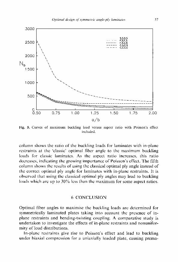
For comparative purposes, the 0ore values for plates where Poisson's effect is neglected are shown in Fig. 4. A comparison of Figs 3 and 4 indicates that the 0op, values differ substantially for the cases including and excluding Poisson's effect. Figure 5 shows the maximum buckling load N/, corresponding to the 0opt values shown in Fig. 3. Corresponding results for plates with Poisson's effect neglected are shown in Fig. 6. It is evident from Figs 5 and 6 that plates subject to Poisson's effect will exhibit premature instability, indicating the need to ascertain the presence or absence of restrained edges for design purposes. The discontinuities in the relationships between r and 0opt shown in Fig. 3 are due to changes in the buckling modes. 4
The consequences of neglecting Poisson's effect are studied in Table 5 by comparing the buckling loads at different ply angles for simply supported laminates under uniformly distributed buckling loads. Table 5 clearly illustrates the benefit of taking into account Poisson's effect in the optimisation of laminates which re subject to in-plane restraints. The third
90
Oopt
75
60
45
50
15
0 0.50
S,S,S.S . . . . . . . . . . . . . . F,S,F,S . . . . . . . F,S.C,S . . . . . C.S.C.S
. . . . . . . . C,C,C,C
, ~ _./_-_2_-.i ~ . ~ ~ / ~ ' ~ . . ~ - ~ . .;.:z-- 7 .....
I
I
I
I
I
I u
0.75 1.00 1.25 1.50 1.75 2.00
o//b
Fig. 4. Curves of optimal ply angles versus the aspect ratio with Poisson's effect neglected•
Optimal design o[symmetrie angle-ply laminates 57
3000
2500 I-.. \
2000
Nb 1 500
1 000
"\ "k
\
"k
-.%.
S,S,S,S . . . . . . . . . . . . . . F,S,F,S . . . . . . . F,S,C,S . . . . . C,S,C,S . . . . . . . . C.C.C,C
500 " " ~ " " ' " ' " .......... - t . . . . . . . . .
0 i i ] 0.50 0.75 1.00 1.25 1.50 1.75 2.00
o/b Fig. g. Curves of maximum buckling load versus aspect ratio with Poisson's effect
included.
column shows the ratio of the buckling loads for laminates with in-plane restraints at the 'classic' optimal fiber angle to the maximum buckling loads for classic laminates. As the aspect ratio increases, this ratio decreases, indicating the growing importance of Poisson's effect. The fifth column shows the results of using the classical optimal ply angle instead of the correct optimal ply angle for laminates with in-plane restraints. It is observed that using the classical optimal ply angles may lead to buckling loads which are up to 30% less than the maximum for some aspect ratios.
6 CONCLUSION
Optimal fiber angles to maximise the buckling loads are determined for symmetrically laminated plates taking into account the presence of in- plane restraints and bending-twisting coupling. A comparative study is undertaken to investigate the effects of in-plane restraints and nonunifor- mity of load distributions.
In-plane restraints give rise to Poisson's effect and lead to buckling under biaxial compression for a uniaxially loaded plate, causing prema-

58
.3000
M. Walker, S. Adali, V. E. VeHienko
2 5 0 0
2 0 0 0
\ % "%
\
S.S,S,S .............. F.S,F,S ....... S.F.C.S ..... C.S.C.S . . . . . . . . C,C,C,C
N b '\%
-\ 1 500 ~.\
k
k
"k
1 0 0 0 ~ .
0 0 .50 0 .75 1 .00 1 .25 1 .50 1 .75 2 .00
o/b Fig. 6. Curves o f maximum buckling load versus aspect ratio with Poisson's effect
neglected.
TABLE 5 Comparison of O'ipt and Buckling Loads for Laminates With and Without Poisson's Effect
" N p ( D P ~/ P p ' r 0 opt N p (0',Wt)/ 0 ,Ppt b ~v op, ,/ N ~, (0 opt )/
N~(O'opt) Nh (0opt) t' , " ' N (0opt)
0-5 0 '~ 1 0 f I 1
0.8 0' 1 0 I 1 1-0 4 5 . 7 0.57 0 ' 0-75 1.31
1-3 48.3 ~ 0-43 2 4 - 5 0.56 1.32
1-5 4 1 . 2 0.43 2 6 . 5 0-50 1-15
1-8 3 3 . 8 0-42 2 4 . 5 0.48 1-05
2.0 44-0 ~ 0-36 2 3 . 5 0.45 1-23
ture instability. The results show that the reduction in the buckling load depends on the aspect ratio and can be substantial for higher aspect ratios. In all cases of buckling loads, this reduction is more than 50% for an aspect ratio of 2. It is found that the differences in the optimal values of the ply angles are also considerable and increase as the aspect ratio becomes larger. These results clearly illustrate the extent of error which will be introduced into the analysis and design of composite

Optimal design (?[symmetric angle-ply laminates 59
laminates in the presence of in-plane restraints if Poisson's effect is not accounted for.
An interesting outcome of the study is the results pertaining to the effects of distributions of in-plane compressive loads on the optimal designs. Tables l ~ indicate that, in general, Oopt becomes smaller and the buckling load larger as the in-plane loads become more evenly distributed. Moreover , the differences in the Oopt values of classical and present cases, in general, also increase as the compressive loads become more uniform. However, the ratio r, , N y N t , does not show a clear trend.
Results are presented for combinat ions of simply-supported, clamped and free boundary conditions. Significant differences in the optimal fiber orientations and buckling loads are observed for the cases with and with- out Poisson's effect. Similarly, if the compressive loads are nonuniform, a uniform approximation will lead to nonconservative estimates of the buckling load.
R E F E R E N C E S
1. Narita, Y. & Leissa, A. W., Buckling studies for simply supported symme- trically laminated rectangular plates. Int. J. Mech. Sci., 32 (1990) 909 24.
2. Kam, T. Y. & Chang, R. R., Buckling of shear deformable laminated composite plates. Composite Structures, 22 (1992) 223 34.
3. Lee, Y. J., Lin, H. J. & Lin, C. C., Buckling analysis of composite laminates. Composite Structures, 12 (1989) 133-48.
4. Walker, M., Adali, S. & Verijenko, V., Optimal design of symmetric lami- nates for maximum buckling load including the effects of bending-twisting coupling. Computers and Structures, 58 (1996) 313 319.
5. Harris, G. Z., The buckling of orthotropic rectangular plates including the effects of lateral edge restraints. Int. J. Solids and Structures, 11 (1975) 877 85.
6. Sherbourne, A. N. & Pandey, M. D., Effects of in-plane restraints on the stability of laminated composite plates. Composite Structures, 20 (1992) 73 81.
7. Obraztsov, I. F. & Vasil'ev, V. V., Optimal design of composite structures. In Handbook of Composites, Vol. 2--Structures and Design (Edited by C. T. Herakovich & Y. M. Tarnopolskii), pp. 3 84. North Holland, Amsterdam, 1989.
8. Papazoglou, V. J., Tsouvalis, N. G. & Kyriakopoulos, G. D., Buckling of unsymmetric laminates under linearly varying, biaxial in-plane loads, combined with shear. Composite Structures 20 (1992) 155 63.
9. Chai, G. B. & Khong, P. W., The effect of varying the support conditions on the buckling of laminated composite plates. Composite Structures, 24 (1993) 99 106.
10. Chai, G. B., Ooi, K. T. & Khong, P. W., Buckling strength optimisation of laminated composite plates. Computers and Structures, 46 (1993) 77 82.

60 M. Walker. S. Adali, V. E. Ver(jenko
11. Walker, M., Adali, S. & Verijenko, V. E., Optimal design of laminated composite plates for maximum buckling load subject to in-plane restraints using the EEM. In Proceedings q[ Computer Aided Design in Composite Material Technology (CADCOMP 94) (Edited by W. R. Blain, W. P. De Wilde & C. A. Brebbia) Southampton, UK, 29 June 12 July 1994.
12. Reddy, J. N., Energy and Variational Methods in Applied Mechanics. John Wiley & Sons, New York, 1984.
13. Haftka, R. T. & Gfirdal, Z., Elements of Structural Optimisation, 3rd edition. Kluwer Academic Publishers, Dordrecht, 1992.