optimal control using state-dependent riccati …optimal control using state-dependent riccati...
TRANSCRIPT
Abstract— This paper presents a nonlinear control for a
hydraulic actuator with significant nonlinearities. These are the key factors causing delay and error in the hydraulic actuation response and highly limit the performances of the classical linear control. Hence, a nonlinear control design based on the mathematical model of the hydraulic actuator is employed.
The proposed approach consists of a nonlinear feedback control based on the state-dependent Riccati equation (SDRE). The control performance is demonstrated by both simulations and real-time experiments.
The experimental results validate the proposed approach and highlight a good accordance with simulations.
Index Terms— Hydraulic actuator, optimal control, SDRE, Riccati equation, nonlinear, tracking, real-time.
I. INTRODUCTION
YDRAULIC actuators employ hydraulic pressure to drive an output member. These are used where high speed
and large forces are required. The fluid used in hydraulic actuator is highly incompressible so that pressure applied can be transmitted instantaneously to the attached member.
Hydraulic components, because of their high speed and pressure capabilities, can provide high power output with small weight and size in comparison to electric system components. Hydraulic actuators can be found in transportations, industrial machineries, seismic applications [1], and earth moving equipments. However, the dynamics of hydraulic systems are highly nonlinear [2] due to the pressure-flow rate relationship, the dead band of the control valve and the frictions. These nonlinearities highly limit the performance achieved by the classical linear controller.
In the past, much of the work in the control of hydraulic systems has used linear model [3] or local linearization of the nonlinear dynamics about the nominal operating point [4]. Suitable adaptive approaches are employed when there is no knowledge of the parameter values [5], [6]. In order to take system uncertainties into account, robust approaches can be adopted [7], [8]. In [9], a sliding mode control
F. Liccardo is with the Dipartimento di Ingegneria Industriale, Università degli Studi di Napoli Federico II, 80125 ITALY (e-mail: [email protected])
S. Strano is with the Dipartimento di Ingegneria Industriale, Università degli Studi di Napoli Federico II, 80125 ITALY (corresponding author, phone: +390817683277; e-mail: [email protected]).
M. Terzo is with the Dipartimento di Ingegneria Industriale, Università degli Studi di Napoli Federico II, 80125 ITALY, (e-mail: [email protected]).
applied to an asymmetric single-rod cylinder was presented. In this paper a SDRE-based control for a hydraulic
actuator is proposed and applied to a hydraulic cylinder of a seismic test bench. The basic idea of the SDRE technique is to capture the nonlinearities by bringing the nonlinear system to a linear structure having state-dependent coefficient (SDC) matrices, and minimizing a nonlinear performance index having a quadratic-like structure [10]. The suboptimal control action can be obtained solving online an algebraic Riccati equation (ARE) using the SDC matrices [11].
This paper continues the work done in [12] and [13] and shows experimental results in order to validate the proposed nonlinear approach.
The rest of the paper is organized as follows: a description of the proposed control is given in Section II. In Section III the nonlinear model of the hydraulic actuator is derived and in Section IV the control has been particularized the specific system. Simulation results are reported in Section V and in Section VI the main experimental results are presented.
II. SDRE FORMULATION
Consider a nonlinear observable systems represented in general form by equations
),( uxfx (1)
where nx and mu are the state and the control respectively.
Assume that the origin is an equilibrium point and suppose that the dynamic model of the system can be placed in the SDC form
uxBxxAx )()( . (2)
Consider the autonomous, infinite-horizon, nonlinear
regulator problem of minimizing the performance index
dtRuuQxxJ TT
02
1 (3)
with respect to the state x and the control u, subject to the
nonlinear differential constraints (2); where 0Q and
0R are symmetric weighting matrices. The SDRE control method provides an approximate nonlinear feedback solution of the above problem. The feedback gain equation is given as
Optimal Control Using State-dependent Riccati Equation (SDRE) for a Hydraulic Actuator
F. Liccardo, S. Strano and M. Terzo
H
Proceedings of the World Congress on Engineering 2013 Vol III, WCE 2013, July 3 - 5, 2013, London, U.K.
ISBN: 978-988-19252-9-9 ISSN: 2078-0958 (Print); ISSN: 2078-0966 (Online)
WCE 2013
)()()( T1 xPxBRxK (4)
where )(xP is the symmetric, positive-definite solution
of the SDRE of the form
0)()()()(
)()()()(T1
T
xPxBRxBxP
QxAxPxPxA (5)
The SDRE controller can be implemented as a
servomechanism, similar to the that of a linear quadratic regulator [14]. Given a desired state trajectory dx , the
SDRE servo control action is then given by
))(()(T1dSD xxxPxBRu . (6)
III. DYNAMICAL MODEL OF THE HYDRAULIC ACTUATION
SYSTEM
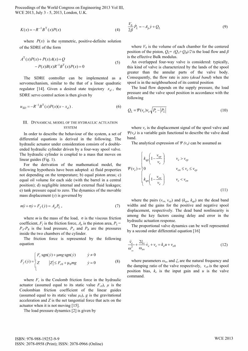
In order to describe the behaviour of the system, a set of differential equations is derived in the following. The hydraulic actuator under consideration consists of a double-ended hydraulic cylinder driven by a four-way spool valve. The hydraulic cylinder is coupled to a mass that moves on linear guides (Fig. 1).
For the derivation of the mathematical model, the following hypothesis have been adopted: a) fluid properties not depending on the temperature; b) equal piston areas; c) equal oil volume for each side (with the barrel in a central position); d) negligible internal and external fluid leakages; e) tank pressure equal to zero. The dynamics of the movable mass displacement (y) is governed by
Lpf PAyFyym )(σ , (7)
where m is the mass of the load, σ is the viscous friction
coefficient, Ff is the friction force, Ap is the piston area, PL = PA-PB is the load pressure, PA and PB are the pressures inside the two chambers of the cylinder.
The friction force is represented by the following equation
0 μ
0 )sgn(μ)sgn(
)(00 ymgFZZ
yymgyF
yFc
c
f
(8)
where Fc is the Coulomb friction force in the hydraulic
actuator (assumed equal to its static value Fc0), μ is the Coulombian friction coefficient of the linear guides (assumed equal to its static value μ0), g is the gravitational acceleration and Z is the net tangential force that acts on the actuator when it is not moving [15].
The load pressure dynamics [2] is given by
LpL QyAPβ
V
20 (9)
where V0 is the volume of each chamber for the centered
position of the piston, QL= (QA+QB)/2 is the load flow and β is the effective Bulk modulus.
An overlapped four-way valve is considered: typically, this kind of valve is characterized by the lands of the spool greater than the annular parts of the valve body. Consequently, the flow rate is zero (dead band) when the spool is in the neighbourhood of its central position
The load flow depends on the supply pressure, the load pressure and the valve spool position in accordance with the following
LseeL PPvvΨQ )( (10)
where ve is the displacement signal of the spool valve and
Ψ(ve) is a variable gain functional to describe the valve dead band.
The analytical expression of Ψ (ve) can be assumed as
enee
enqn
epeen
epee
epqp
e
vvv
vk
vvv
vvv
vk
vΨ
1
0
1
)(
(11) where the pairs (ven, vep) and (kqn, kqp) are the dead band
widths and the gains for the positive and negative spool displacement, respectively. The dead band nonlinearity is among the key factors causing delay and error in the hydraulic actuation response.
The proportional valve dynamics can be well represented by a second order differential equation [16]
02 ω
ξ2
ωeeee
nv
ve vukvvv
nv
(12)
where parameters ωnv and ξv are the natural frequency and
the damping ratio of the valve respectively, ve0 is the spool position bias, ke is the input gain and u is the valve command.
Proceedings of the World Congress on Engineering 2013 Vol III, WCE 2013, July 3 - 5, 2013, London, U.K.
ISBN: 978-988-19252-9-9 ISSN: 2078-0958 (Print); ISSN: 2078-0966 (Online)
WCE 2013
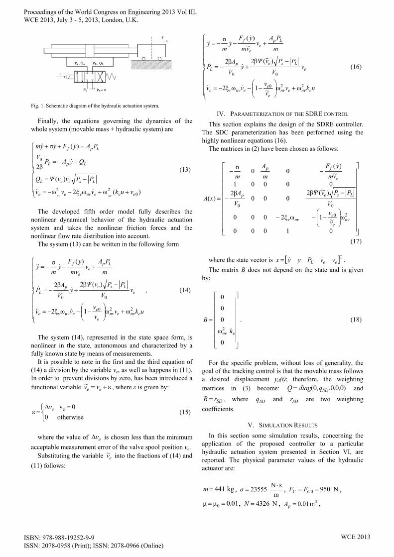
Fig. 1. Schematic diagram of the hydraulic actuation system.
Finally, the equations governing the dynamics of the
whole system (movable mass + hydraulic system) are
)(ωωξ2ω
)(
β2
)(σ
022
0
eeenvvee
LseeL
LpL
Lpf
vukvvv
PPvvΨQ
QyAPV
PAyFyym
nvnv
(13)
The developed fifth order model fully describes the
nonlinear dynamical behavior of the hydraulic actuation system and takes the nonlinear friction forces and the nonlinear flow rate distribution into account.
The system (13) can be written in the following form
ukvv
vvv
vV
PPvΨy
V
AP
m
PAv
mv
yFy
my
envenve
eenvve
eLsep
L
Lpe
e
f
220
00
ωω1ωξ2
)(β2β2
)(σ
, (14)
The system (14), represented in the state space form, is
nonlinear in the state, autonomous and characterized by a fully known state by means of measurements.
It is possible to note in the first and the third equation of (14) a division by the variable ve, as well as happens in (11). In order to prevent divisions by zero, has been introduced a functional variable ε~ ee vv , where ε is given by:
otherwise 0
0 vε eev
(15)
where the value of ev is chosen less than the minimum
acceptable measurement error of the valve spool position ve. Substituting the variable ev~ into the fractions of (14) and
(11) follows:
ukvv
vvv
vV
PPvΨy
V
AP
m
PAv
vm
yFy
my
envenve
eenvve
eLsep
L
Lpe
e
f
220
00
ωω~1ωξ2
)~(β2β2
~)(σ
(16)
IV. PARAMETERIZATION OF THE SDRE CONTROL
This section explains the design of the SDRE controller. The SDC parameterization has been performed using the highly nonlinear equations (16).
The matrices in (2) have been chosen as follows:
01000
ω~1ωξ2000
)~(β2000
β200001
~)(
00σ
)(
20
00
nve
envv
Lsep
e
fp
v
v
V
PPvΨ
V
A
vm
yF
m
A
m
xA
(17)
where the state vector is TeeL vvPyyx .
The matrix B does not depend on the state and is given by:
0
ω
0
0
0
2env k
B . (18)
For the specific problem, without loss of generality, the
goal of the tracking control is that the movable mass follows a desired displacement yd(t); therefore, the weighting matrices in (3) become: )0,0,0,,0( SDqdiagQ and
SDrR , where SDq and SDr are two weighting
coefficients.
V. SIMULATION RESULTS
In this section some simulation results, concerning the application of the proposed controller to a particular hydraulic actuation system presented in Section VI, are reported. The physical parameter values of the hydraulic actuator are:
kg441m , m
sN 23555
σ , N9500 CC FF ,
01.0μμ 0 , N 4326N , 2m 0.01pA ,
Proceedings of the World Congress on Engineering 2013 Vol III, WCE 2013, July 3 - 5, 2013, London, U.K.
ISBN: 978-988-19252-9-9 ISSN: 2078-0958 (Print); ISSN: 2078-0966 (Online)
WCE 2013

30 m 004.0V , Pa 1e9β ,
2
1
3
PaVs
m 76.15e
qpk ,
2
1
3
PaVs
m 75.86e
qnk , V 43.0epv , V 21.0env ,
V 01.00 ev , 49.0ek , 30.152ω nv , Pa 6e6SP . These parameters have been obtained with a parameter
identification technique [13]. The controller is used for tracking sinusoidal motion
trajectory characterized by an amplitude of 0.04 m and a frequency of 1 Hz.
The simulation results reported in Fig. 2 consist of comparisons between the target and the effective movable mass displacement, the tracking error ( dyy ) and the
control action.
Fig. 2. Simulation results of the nonlinear SDRE-based control.
The maximum value of the tracking error is about 0.008 m. The difference between the peak to peak amplitude of the effective displacement and the target one is about 0.001 m, and the actuation system phase lag is of 0.03 s.
To verify the prediction capacity of simulation, the results reported in Fig. 2 will be compared with the experimental ones.
VI. REAL-TIME EXPERIMENTS
In order to test the effectiveness of the proposed nonlinear tracking controller, experimental studies are conducted on the hydraulic actuation system of the test rig shown in Fig. 3.
A. The experimental test rig
The experimental test rig is a machine utilized to perform shear tests on seismic isolators [17], [18]. The actuation system consists of a double-ended hydraulic actuator placed between a fixed base and a sliding table (1.8 m x 1.59 m). The hydraulic actuator is constituted by a mobile barrel, integral with the sliding table (A), and two piston rods linked to the fixed base (B) (Fig. 3).
The isolator under test (C) is located between the sliding table and a slide that can move vertically with respect to the horizontal reaction structure (D).
A hydraulic jack (E) is positioned between the vertical reaction structure (F) and the slide in order to make the isolator under test vertically loaded.
The supply circuit of the hydraulic actuator is mainly constituted by an axial piston pump, powered by a 75 kW AC electric motor, a pressure relief valve and a four way-three position proportional valve. The pump is characterized by a variable displacement and it is able to generate a maximum pressure of 210 bar and a maximum flow rate equal to 313 l/min.
Fig. 3. Experimental test rig.
The maximum horizontal force is 190 kN, the maximum
speed is 2.2 m/s and the maximum stroke is 0.4 m (± 0.2 m). The removal of the reaction structures allows the testing
machine to be used as a shaking table [19]. The full-state feedback has been obtained with the
following measurements: - table position by means of magnetostrictive position
sensor (FS = 0.4 m - estimated uncertainty = ± 1.2e-4 m);
- pressure in the two chambers of the hydraulic cylinder by means of strain gauge sensor (FS = 400 bar - estimated uncertainty = ± 1 bar);
- valve spool position by means of built-in LVDT sensor;
A dSPACE DS1103 controller board, equipped with a 16-bit A/D and D/A converter, has been used for the real-time experiments. All experiments have been conducted with a sample frequency of 1 kHz. To attenuate the influence of the noise, all measured signals are processed through a low-pass filter. The supplied pressure has been fixed to 6e6 Pa.
B. Experimental Results
The experiments on the seismic isolator testing machine have been conducted without the isolator to be characterize. Hence, the hydraulic actuation system has been utilized only for the sliding table positioning.
For sake of comparison, the experimental validation of the proposed control has been obtained with the same target displacement imposed to the movable mass in the simulations.
The problem of computing the SDRE feedback gains
Proceedings of the World Congress on Engineering 2013 Vol III, WCE 2013, July 3 - 5, 2013, London, U.K.
ISBN: 978-988-19252-9-9 ISSN: 2078-0958 (Print); ISSN: 2078-0966 (Online)
WCE 2013

reduces to solving (5). The proposed approach is based on finding the eigenvalues of the associated Hamiltonian matrix [20]
)(
)()()()(
T
1
xAQ
xBRxBxAxH
T
. (19) The SDRE-based feedback gains have been obtained with
a pole placement algorithm in terms of the stable eigenvalues of H(x).
The SDRE feedback action has been implemented as a C-code function downloaded to the controller board and implemented in real-time.
In Fig. 4 are reported the experimental results in terms of the target and the experimental effective table displacement, the tracking error and the control action.
Fig. 4. Experimental results of the nonlinear SDRE-based control.
Analyzing the experimental results, it is possible to assert
that the maximum amplitude error is equal to 3e-5 m and the actuator phase lag is equal to 0.035 s. Concerning the tracking error, its maximum value is equal to 0.009 m.
The experimental results agrees with the results predicted in simulation environment.
It has been experimentally demonstrated that the proposed nonlinear controller can achieve very good performance in terms of tracking control and stability.
VII. CONCLUSION
In this paper has been proposed an optimal control using the SDRE for a hydraulic actuator. A fifth order dynamic model of the system has been derived taking into account the typical nonlinearities of the hydraulic actuators. The parameterization of the SDRE feedback control has been obtained directly from the fifth order model. The real-time implementation of the SDRE nonlinear optimal problem has been performed with a pole placement algorithm in terms of the stable eigenvalues of the Hamiltonian matrix.
Experiments have been conducted on the hydraulic actuation system equipped on a seismic isolator test rig. The
experimental results validate the proposed approach and highlight a good accordance with simulation results.
REFERENCES [1] J.P. Conte, T.L. Trombetti, “Linear dynamic modeling of a uniaxial
servo-hydraulic shaking table system,” Earthquake Engineering and Structural Dynamics, vol. 29, no. 9, pp. 1375 – 1404, 2000.
[2] H.E. Merritt, Hydraulic control systems, John Wiley & Sons, New York, USA, 1967.
[3] A. R. Plummer and N. D. Vaughan, “Robust adaptive control for hydraulic servosystems,” ASME Journal of Dynamic Systems, Measurement, and Control, vol. 118, no. 2, pp. 237–244, 1996.
[4] Y. Xu, H. Hua, J. Han, “Modeling and controller design of a shaking table in an active structural control system,” Mechanical System and Signal Processing, vol. 22, pp. 1917 – 1923, 2008.
[5] R. Russo, M. Terzo, “Design of an adaptive control for a magnetorheological fluid brake with model parameters depending on temperature and speed,” Smart Materials and Structures, vol. 20, no. 11, 115003 (9pp), 2011.
[6] D.P. Stoten, E.G. Gomez, “Adaptive control of shaking tables using the minimal control synthesis algorithm,” Phil. Trans. R. Soc. Lond., vol. 359, pp. 1697 – 1723, 2001.
[7] B. Yao, F. Bu, J. Reedy, G.T.C. Chiu, “Adaptive robust motion control of single-rod hydraulic actuators: theory and experiments,” IEEE/ASME Transactions on Mechatronics, vol.5, no.1, pp. 79 – 91, 2000.
[8] Y. Lin, Y. Shi, R. Burton, “Modeling and Robust Discrete-Time Sliding-Mode Control Design for a Fluid Power Electrohydraulic Actuator (EHA) System,” IEEE/ASME Transactions on Mechatronics, vol.18, no.1, pp.1-10, 2013.
[9] D. Hisseine, “Robust tracking control for a hydraulic actuation system,” Proceedings of 2005 IEEE Conference on Control Applications, pp. 422 – 427, 2005.
[10] T. Çimen, “Survey of State-Dependent Riccati Equation in Nonlinear Optimal Feedback Control Synthesis,” AIAA Journal of Guidance, Control, and Dynamics, vol. 35, no. 4, pp. 1025 – 1047, 2012.
[11] R. Russo, M. Terzo, “Modelling, parameter identification, and control of a shear mode magnetorheological device,” Proceedings of the Institution of Mechanical Engineers, Part I: Journal of Systems and Control Engineering, vol. 225, no. 5, pp. 549 – 562, 2011.
[12] S. Pagano, R. Russo, S. Strano, M. Terzo, “Modelling and control of a hydraulically actuated shaking table employed for vibration absorber testing,” (ESDA2012-82118), in Proc. of the ASME 11th Biennial Conference on Engineering Systems Design and Analysis (ESDA2012), vol. 1, pp. 651 – 660, 2012.
[13] S. Pagano, R. Russo, S. Strano, M. Terzo, “Non-linear modelling and optimal control of a hydraulically actuated seismic isolator test rig,” Mechanical Systems and Signal Processing, vol. 35, no. 1 – 2, pp. 255 – 278, 2013.
[14] J.R. Cloutier, D.T. Stansbery, “Control of a continuously stirred tank reactor using an asymmetric solution of the state-dependent Riccati equation,” in Proc. of the IEEE. International Conference on Control, vol.2, pp. 893 – 898, 1999.
[15] A. Bonchis, P. Corke, D. Rye, “A pressure-based, velocity independent, friction model for asymmetric hydraulic cylinders,” in Proc. of the IEEE International Conference on Robotics and Automation, vol. 3, pp. 1746 – 1751, 1999.
[16] L. Márton, S. Fodor, N. Sepehri, “A practical method for friction identification in hydraulic actuators,” Mechatronics, vol. 21, pp. 350 – 356, 2011.
[17] M. Cardone, S. Strano, “Fluid-dynamic analysis of earthquake shaking table hydraulic circuit,” (ESDA2012-82422), in Proc. of the ASME 11th Biennial Conference on Engineering Systems Design and Analysis (ESDA2012), vol. 2, pp. 343 – 350, 2012.
[18] S. Pagano, M. Russo, S. Strano, and M. Terzo, “A mixed approach for the control of a testing equipment employed for earthquake isolation systems,” Proceedings of the Institution of Mechanical Engineers, Part C: Journal of Mechanical Engineering Science, DOI: 10.1177/0954406213484424, 2013.
[19] G. Di Massa, S. Pagano, E. Rocca, S. Strano, “Sensitive equipments on WRS-BTU isolators,” Meccanica, DOI: 10.1007/s11012-013-9708-9, 2013.
[20] E.B. Erdem , A.G. Alleyne, “Experimental real-time SDRE control of an under actuated robot,” in Proc. of the 40th IEEE Conference on Decision and Control, vol. 3, pp. 2986 – 2991, 2001.
Proceedings of the World Congress on Engineering 2013 Vol III, WCE 2013, July 3 - 5, 2013, London, U.K.
ISBN: 978-988-19252-9-9 ISSN: 2078-0958 (Print); ISSN: 2078-0966 (Online)
WCE 2013