optimal control of gravity-tractor spacecraft for … control of gravity-tractor spacecraft for...
TRANSCRIPT
Optimal Control of Gravity-Tractor Spacecraftfor Asteroid Deflection
Joris T. Olympio∗
ESA, 2200 AG Noordwijk, The Netherlands
DOI: 10.2514/1.46378
Near-Earth objects can pose amajor threat to Earth. New ideas and concepts are continually proposed tomitigate
possible impact. Among them, the gravity tractor is promising and has been the focus of many recent studies on
asteroid deflection. The gravity-tractor concept is studied and trajectories are designed to lessen the risk of impact of
a near-Earth object. By means of a mathematical model of the gravity tractor, a high-fidelity trajectory design
method for deflection is proposed. The optimal deflection of an asteroid is computed by an indirect method, and the
trajectory of the spacecraft is deducedby an inversion of dynamics andoptimal control.When thedeflection achieved
is compared with results published to date, the better performance of the deflection is clear. This paper shows that
current literature analyses of the gravity-tractor design may be nonoptimal because the assumption made about the
control penalizes the concept. The use of optimal control actually improves the robustness of the designed trajectory
while obtaining higher deflection.
Nomenclature
A = asteroid push acceleration, m=s2
a = asteroid semimajor axis, md = equilibrium distance between the asteroid and
the spacecraft, mE = energyFth = spacecraft thruster thrust amplitude, Nf = dynamic equationsH = HamiltonianIsp = spacecraft thruster specific impulse, smf = spacecraft dry mass, kgm = mass, kgr = asteroid radius, mr = heliocentric position, mT = total spacecraft thrust force, Ntf = end of deflection mission, MJDts = potential impact date on Earth, MJDt0 = start of deflection mission, MJDu = spacecraft unit control vectoruA = virtual asteroid unit control vectorv = heliocentric velocity, m=sx = state vector�r = spacecraft relative position to the Asteroid, m�v = spacecraft relative velocity to the Asteroid, m=s�� = deflection, m� = costate vector� = gravitational parameter, m3=s2
�f = Lagrange scalar for constraint�f = transversality conditions� = thruster cant angle, rad f = terminal constraints
Subscripts
ast = asteroidEarth = Earth
sc = spacecraftsun = sun
I. Introduction
N EAR-EARTH objects (NEOs) have attracted a lot of attentionfrom astronomers in recent years. The possibility of an NEO
impacting Earth, with dramatic consequences, motivates scientistsand engineers to devise original and innovative ideas to disrupt ordeflect asteroids. The latter option is often preferred [1]. Aside frompolitical issues arising from deploying nuclear devices for asteroidfragmentation, disrupting an asteroid increases the risk of producingnew impactors, particularly when the NEO is a porous rubble-pileasteroid.With sufficient warning time, deflection techniques are thusvery attractive to avert an impact.
Thegravity tractorwas introduced recently byLu andLove [2] as apossible means of asteroid deflection and asteroid impact mitigation.During close proximity of a spacecraft to an asteroid, the mutualgravitational acceleration perturbs both objects’dynamics.When thespacecraft can thrust in a direction that balances the gravitationalforce exerted by the asteroid on the spacecraft, the asteroid isaccelerated and deviates slightly from its original path. This caneventually perturb the asteroid orbit, and in the long run will result ina significant deflection, preventing a potential impact on Earth. Oneof the main advantages of this thrusting deflection technique is that itis relatively independent of the physical properties of the asteroid,such as its composition, although the shape and gravityfieldmight bemore relevant [3].
The gravity-tractor concept has been the focus of many studiessince it was introduced a few years ago.Most of the studies, however,makemajor assumptions about the deflection strategy and only focuson simple hovering control.
Wie [4] studies the gravity-tractor hovering dynamics. Some of hiswork also focus on the dynamics of solar sails as a gravity tractor. Theconcept is actually quite attractive, as the spacecraft in this case hasvery limited thrust requirement, although maintaining a non-Keplerian displaced orbit [5] or distant halo-type orbit, with orwithout solar sail for an autonomous vehicle, is not straightforward.
Fashnestock and Scheeres [3] study the control requirement for thecoupled rotational and translational dynamics, in addition to thesystem specifications. With a rigorous model, this paper points outthe difficulty of the control problem.
Broschart and Scheeres [6] study the hovering dynamics in thecase of scientific observation of a small asteroid. Although theauthors compute the equilibrium condition, the dynamic influence ofthe sun is neglected. Indeed, during inertial hovering for asteroid
Received 17 July 2009; revision received 11 January 2010; accepted forpublication 19 January 2010. Copyright © 2010 by Joris Olympio. Publishedby the American Institute of Aeronautics and Astronautics, Inc., withpermission. Copies of this paper may be made for personal or internal use, oncondition that the copier pay the $10.00 per-copy fee to the CopyrightClearance Center, Inc., 222 Rosewood Drive, Danvers, MA 01923; includethe code 0731-5090/10 and $10.00 in correspondence with the CCC.
∗Research Fellow, Advanced Concepts Team, European Space Researchand Technology Centre, Keplerlaan 1, Postbus 299. Member AIAA.
JOURNAL OF GUIDANCE, CONTROL, AND DYNAMICS
Vol. 33, No. 3, May–June 2010
823
surface mapping, the time of operation is too small for the sunactually to have an influence on the asteroid dynamics. Some work[7] also proposes a method to compute the hovering dynamics in thecase of nonspherical asteroids.
In [8], the author performs local optimization for thegravity-tractorconcept from launch to the rendezvous, to show that the gravity-tractor concept performance usually depends heavily on the design.
In this paper, the entiremission concept is studied, from the start ofthedeflection to theend. Inparticular, it is shown that current literatureassumptions limit the efficiency of the gravity-tractor concept andmay also lead to nonrealizable missions. On the other hand, acomplete study shows that not only is the conceptmuchmore reliablethan is shown in the literature, but as a mission, it is also more robust.This paper proposes an approach to optimal deflection of an asteroidwith a gravity-tractor spacecraft. The approach can be split into twoparts. First, the optimal deflection trajectory of the asteroid iscomputed, regardless of the spacecraft dynamics. In the second step,through dynamic inversion and optimal control, the spacecrafttrajectory that would eventually optimally deflect the asteroid isestimated. Finally, the approach is applied to the deflection of asteroid2007VK184,oneof thecurrent asteroidsgraded1on theTorinoscale.
II. Problem Statement
A. Analytical Deflection Formula
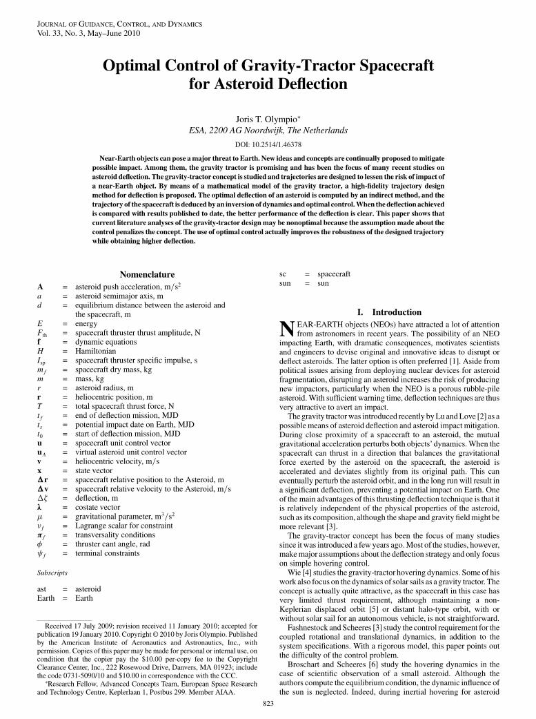
When potential asteroid impact is monitored, the location of theimpact is plotted on a projection plane, which often corresponds tothe B plane at Earth and at the time of potential impact [9]. Therequired deflection to avoid an impact is given by the distance fromthe undeflected impact point to the Earth’s surface. For instance, inFig. 1, the impact location (represented by an uncertainty ellipsebecause of inaccurate orbital parameters) is outside the Earth imageand no impact on Earth is possible. Sometimes, however, the closestpoint location is not in the Earth image, but the close approach of theasteroid still leads to future impact conditions. The point of closestapproach is said to be in a keyhole [9,10], which is a preimage of theEarth on the B plane, at the date of encounter, that leads to a futureimpact. Thus, if the asteroid passes through a keyhole, it will impacton the Earth after a resonant return.
If actions are required to mitigate a possible asteroid impact, aresponse is to deflect the asteroid by a given amount such that theimpact point misses the Earth shadow or the keyhole. A good pointabout keyholes, though, is that they are usually smaller than the Earthshadow, and thus a small deflection would be sufficient to nullify therisk of impact. Izzo [11] generalizes the asteroid deflection formula:
���� 3avEarth�ts� sin ��
Ztf
t0
�ts � t��vast�t� � A�t�� dt (1)
which is used to compute the deflection achieved on the B planedefined at the date ts. The accelerationA�t� can model an impact or,in our case, a continuous gravitational acceleration. This formulashows that the earlier the deflection starts, the larger the finaldeflection. If a direct impact is to be mitigated,�� should be at leastof one Earth radius.
B. Gravity-Tractor Concept
The gravity tractor [2] uses mutual gravitational acceleration tomodify the course of the asteroid with which it is in interaction. Asshown in Fig. 2, the gravity-tractor spacecraft has at least twothrusters, which thrust slightly inclined in opposite directions. Thethrusters are tilted, so they do not impinge the asteroid surface with
ions coming from the electric propulsion system (e.g., the thrusters)and eventually reduce the efficiency of the tug system [12].
From Fig. 2, the total thrust force is then
T � 2Fth cos ~� (2)
with ~�� sin�1�rd� � �. The distance d must be higher than the
highest dimension of the asteroid. Lu andLove [2] considerd� 1:5rin the original concept. The condition for the spacecraft thrusters tocompensate for the attraction of the asteroid is simply
T
msc
� �ast
d2eq(3)
A static equilibrium is then created when the spacecraft thrusts in thedirection of the local gravity.
Any configuration is possible when d is chosen such that deq d,as long as there is sufficient thrust acceleration for deq > r. Thequestion is only whether to have a constant or a variable relativedistance d [13]. In this paper, it is assumed that the thrust amplitudeFth is constant when the thrusters are on. This point will, however, bediscussed later.
The nonperfect shape of the asteroid introduces harmonics in theasteroid’s gravitational potential, which might impose a nonconstantdistance deq when the asteroid is rotating. For simplicity, this will notbe taken into account in the present study, and the asteroid gravitymodel is assumed to be a homogeneous sphere.
C. General Dynamics
The gravity-tractor spacecraft evolves under the influence of thesun and the asteroid to deflect. Newtonian dynamics describingthe relative motion of the spacecraft with respect to the asteroid inthe supposed inertial heliocentric reference frame give
f sc�xsc;xast;u; t� �
�v�t���sun
��r�t��rast�t�k�r�t��rast�t�k3
� rast�t�krast�t�k3
�� �ast
�r�t�k�r�t�k3
�1� msc�t�
mast
�� T
msc�t�u�t�
� 2Fth
g0Ispku�t�k
2664
3775 (4)
with
�r � rsc�t� � rast�t�; �v� vsc�t� � vast�t�xsc � ��r;�v; msc�
One could have been tempted to useTschauner–Hempel equations[14] instead of Eq. (4), as is done in numerous studies [10], when the
Fig. 1 B plane and keyhole (MOID denotes the minimum orbital
intersection distance).
824 OLYMPIO

asteroid deflected trajectory is actually not taken into account. This isa valid assumption as long as time spans are small and the effect of thetowing is not studied. Indeed, when Tschauner–Hempel equationsare used, the reference ellipse is an osculating ellipse of the deflectedasteroid orbit that changes at all times.
Concurrently with this dynamic, the dynamic of the asteroid isconsidered, which is no longer given by the ephemeris, as it is beingdeflected by the gravity-tractor spacecraft:
f ast�xast;xsc; t� �vast�t�
��sunrast�t�krast�t�k3
� �sc�r�t�k�r�t�k3
� �(5)
Studying the motion of the center of mass of the asteroid–gravity-tractor system gives
d2rast�scdt2
� �sun
rast�sckrast�sck3
T
mast
u
which shows that when the spacecraft thrusts to balance thegravitational force exerted by the asteroid, the entire system is indeedaccelerated [5].
D. Control Problem
Because dynamic equations (4) and (5) are highly nonlinear,finding the control u that would enforce a constant distance d to theasteroid during the entire mission is difficult numerically. First, thedifference in scale between�r and rast requires robust and accurateintegrations. Second, to impose a distance d during the entiremission, state constraints must be used, which limit the solutionmethod mostly to direct approaches. To maintain a good quality ofsolution, and because of the long time of flight, the number of nodesin the transcription [15] become significant. Otherwise, consideringthe dynamics and the constant control during a time step, thespacecraft dynamics are unlikely to respect the towing distance and,in some cases, if the thrust acceleration is not sufficient, thecomputation might result in the spacecraft crashing on the asteroid.
Most studies are limited to the relative motion in a circularreference frame and do not actually consider the deflection of theasteroid. Among the literature [4,6,7,16], studies related to close-proximity control and hovering above asteroids or small bodies usedeadband controllers. It is apparent that to maintain a spacecraft in aprescribed relative location, deadband control provides the moststraightforward approach. In this case, however, the spacecraft has tothrust while maintaining a relative distance and seeking the optimalsolution.
A new approach that accurately computes both the deflectedasteroid trajectory and the spacecraft control is proposed. First, theoptimal deflected trajectory of the asteroid is found using an indirectmethod. Then from the deflected asteroid trajectory, the spacecrafttrajectory is inferred. This approach is both high-fidelity and robust.
III. Optimal Deflected Asteroid Trajectory
A. Dynamic Problem of a Virtual Asteroid
Avirtual asteroid is introducedwith the statexast � �~rast; ~vast; ~mast�.The initial position and velocity of the virtual asteroid coincide withthe position and velocity of the asteroid to deflect at one given epoch(e.g., just before the beginning of the deflection). The mass of theasteroid is also the initial gravity-tractor mass. From the general
asteroid dynamic equation (5), the dynamics of our virtual asteroidare defined by
~f ast�xast;A; �; t� �~vast�t�
��sun~rast�t�k~rast�t�k3
� ��t�A�t�� 2Fth
g0Isp��t�
264
375 (6)
These dynamics define the motion of the asteroid in a central forcefield (e.g., sun gravitational attraction) and can be subject to adisturbing acceleration A�t���t�. Indeed, the disturbing accelerationA�t���t� replaces the asteroid—spacecraft mutual gravitationacceleration in Eq. (5), although this time the spacecraft dynamics arenot explicitly included. Also, �A�t�; ��t�� is now the control of ourvirtual asteroid. The mass equation accounts for the availablespacecraft fuel mass to deflect the asteroid. The optimal perturbationthat a spacecraft needs to exert on the asteroid to optimally deflect it issought.
The gentle push of the asteroid is due to the spacecraft’s closeproximity. Substituting Eq. (3) in Eq. (5) and comparing with Eq. (6)gives A�t�. That being the case, this acceleration A�t� is bounded,and
A �t� � T
mast
uA (7)
j�j 1 (8)
This constraint indicates the maximum push that the spacecraft caninduce on the asteroid and thus the maximum push that our virtualasteroid can have. In addition, the mass of the virtual asteroid definesthe mass of the gravity tractor. A constraint on the terminal mass isthus given by
f�xast; tf� � ~mast�tf� �mf (9)
which limits the total amount of fuel available for the deflection.The problem is to maximize the objective function, or
performance index,
J�Ztf
t0
�ts � t��vast�t�TA�t����t� dt (10)
given by the deflection equation (1), where the multiplicative termhas been dropped for convenience, as it only depends on the potentialimpact date tf and not on the asteroid or the spacecraft state.Parameters t0 and tf are thus fixed.
B. Optimal Control Problem
The optimization problem is solved using optimal control theory.Considering the dynamic equation (6) and the constraint equation (9),the control �A�t�; ��t�� that maximizes the objective function J inEq. (10) is computed.
Introducing the costate vectors �R�t� and �V�t� and the costatevariable �m�t� [assigned, respectively, to ~rast�t�, ~vast�t�, and ~mast�t�]and the constant Lagrange multiplier �f for the constraint f toaugment the performance index, the Lagrangian is given by
L� J �Ztf
t0
��t�T�dxast
dt� ~fast�xast;A; �; t�
�dt� �f f�xast; tf�
(11)
with ��t�T � ��R�t�T;�V�t�T; �m�t��.Since the objective function is written in the Lagrange form, the
Hamiltonian can be written as
H�xast;�;u; t� � �ts � t��vast�t�TA�t����t� � ��t�T ~fast�xast;A; �; t�(12)
The necessary conditions of optimality can be found by stating thestationarity of the Lagrangian L of the optimization problem. Thisleads to the well-known Euler–Lagrange equations, which describethe dynamics of the costate vectors,
Fig. 2 Gravity-tractor concept [2].
OLYMPIO 825

dxast
dt
T
� @H@�
d�
dt
T
�� @H@x
(13)
and to the boundary conditions of the Euler–Lagrange equations,also called transversality conditions. For instance,
� f�xast;�; tf� � ��tf� � �f@
@xf
(14)
These transversality conditions provide the optimal value of ��tf�.Note that ��t0� is the initial condition and is completely free. Notealso that as the dynamic equations do not depend on themass ~mast�t�,the costate variable �m�t� is constant.
Following calculus of variation theory and themaximumprinciple[17], the optimal control �A��t�; ���t�� is the one maximizing theHamiltonian:
u �A � argmaxuAH�xast;�;A; �; t�
and
H�xast;�;A; t� � �R�t�Trsc�t� � �V�t�T�rsc�t�krsc�t�k3
� S�xast;�;A; �; t� (15)
S�xast;�;A; �; t� ����ts � t�~vast�t� � �V�t��TA�t�
� �m�t�2Fth
g0Isp
���t� (16)
Clearly, the Hamiltonian is maximized for the optimal controldirection:
u �A ��ts � t�~vast�t� � �V�t�k�ts � t�~vast�t� � �V�t�k
(17)
As the control belongs to a compact set (��t� 2 �0; 1�) and appearslinearly in the Hamiltonian, it is in general bang–bang. In particular,S is called a switching function and is simplified to
S�xast;�;A�; �; t� � 2Fth
�cos ~�
mast
k�ts � t�~vast�t�
� �V�t�k ��m�t�g0Isp
���t� (18)
This helps to choose, at each time t, whether the control ��t� shouldreach its upper or lower bound (��t� � 1 or ��t� � 0) to maximizeH.Numerically, ��t� is found by means of smoothing techniques [18].
An interesting feature ofEq. (17) is that the optimal direction of thedisturbing acceleration depends on the direction of the asteroidvelocity ~vast and on how early the deflection process starts.
The optimal control is thus computed by solving a two-pointboundary-value problem (TPBVP) using a shooting method. TheEuler—Lagrange dynamic equations are integrated using the initialconditions �xast�t0�;��t0�� while satisfying the transversalityconditions �f�xast;�; tf� and terminal constraints f�xast; tf�. Thefree vector ��t0� is used to satisfy these endpoint conditions.
C. Discussion
The optimal deflected asteroid trajectory is computed easily, andthe disturbing acceleration is the spacecraft–asteroid mutualgravitational acceleration. A priori thrust phases are the phases[��t� � 1] in which the spacecraft is close to the asteroid and usemutual gravitation to deflect it. The coast phases [��t� � 0] are thephases inwhich the spacecraftmust not perturb the asteroid dynamic.It is then very likely that the optimal way to deflect the asteroid is toalternate between thrust and coast phases. This strategy is highlydependent on the asteroid heliocentric velocity, as shown in Eq. (18).
Great variation in the velocity, and thus high eccentricity of theoriginal orbit, might lead to complex deflection control.
In many studies on the gravity tractor, the main assumption is thatthe spacecraft is fully thrusting, which would assume that ��t� � 1with the present formulation. This assumption facilitates thetheoretical development. But here it is clear that it is, in general, nottrue and that using such an assumption indeed penalizes the concept.
Such a result has many implications. For instance, from anoperational point of view, coast phases are useful to reconfigure thespacecraft, correct any pointing issues, communicate with a groundbase, or measure the changes so far in the asteroid’s orbit. Coast arcsalso make the entire mission more robust. Bearing in mind thatthrusting is the critical point of such amission, it is good to know thatin case of any thrust-amplitude failure, the mission can still berecovered if there is sufficient coast time. It is known that coastphases allowmore security in the thrusting [19]. Given that thrustingis the key element of the deflection strategy, coast phases are requiredfor a fail-safe mission.
IV. Gravity-Tractor Spacecraft Trajectory
A. Inversion of Dynamics During Towing Phases
1. Position
When the spacecraft has to thrust to compensate for gravitationalacceleration from the asteroid, it must be placed on the equilibriumsphere, defined by Eq. (3), and in such a position that the spacecraftthrust vector is aligned with the centers-of-mass line. The desiredposition of the spacecraft is thus readily computed during the towingphases. When the spacecraft is close to the asteroid, the control uA isindeed the direction of themutual gravitational acceleration.With theequilibrium condition between the thrust and the gravitationalacceleration, the relative position vector is given by
�r �t� �
���������������������astmsc�t�T��t�
suA�t� (19)
The mass msc�t� of the spacecraft will slowly decrease as thespacecraft is thrusting.Asmentioned in the Introduction, two optionsare possible.
1) Suppose a constant relative distance�r�t� � d, then��t�varies(assuming Fth is constant), such that the ratio
msc�t�2Fth cos�sin�1�rd� � ��
is constant.2) Suppose that the relative distance �r�t� � d�t� varies, then
Eqs. (2) and (3) give
Table 2 Date and duration of the mission
Potential impact date 17685.5 MJD (2048-06-03)
Minimum warning time 1826 daysMaximum warning time 5478 daysMaximum thrust duration 3897 days (5.3 years)
Table 1 Property of the asteroid 2007 VK184
Epoch 2454600.5 MJD
Semi major axis a 1.726508477921687 AUEccentricity e 0.5698369067437545Inclination i 1.222310015202323 degArgument of perihelion ! 73.0616457437701 degLongitude of ascending node � 254.0587808820642 degMean anomalyM 102.686674978651 degMass mast 3:3 � 109 kgDiameter 130 mRotational rate 0:266 deg =day
826 OLYMPIO
d�t�2 � �astmsc�t�2Fth cos�sin�1� rd�t�� � ��
� 0
which has to be satisfied.Sanchez et al. [13] deduce that a variable-altitude hovering is less
efficient than the constant-altitude option. The authors demonstratethat the constant-altitude option is more efficient by using argumentsabout the mass of the system, disregarding the nonlinearity ofthe dynamics and the optimal control contribution. However, thedifference is so small that it does not seem tomake amajor difference.Indeed, keeping the thrust accelerationvariable seemsmore practical,because keeping a constant altitude might be more complex,particularly for nonhomogeneous rotating asteroids. As ��t� can be 0or 1, the spacecraft’s relative distance to the asteroid k�r�t�k variesbetween dmin and infinity, where dmin is the distance obtained withEq. (3) when the spacecraft has no fuel.
The mass of the spacecraft is readily computed, since thespacecraft is fully thrusting during the towing phases. To obtain thecomplete state of the spacecraft and compute the spacecraft’svelocity during the towing phases, a dynamic inversion method isalso introduced.
2. Velocity and Hovering Control
From the position and mass of the spacecraft, the spacecraftvelocity during the towing phases is deduced. However, since thethrust of the spacecraft is already constrained to balance thegravitational interaction of the asteroid, one would expect the needfor extra thrust acceleration to move the spacecraft into the correctposition and satisfy controllability conditions.
As uA is given by a continuous-function equation (17), thespacecraft position also moves continuously. Over an infinitesimaltime step �t, the required additional thrust acceleration should be thedifference
���t��t dvscdt�t� �t� � dvsc
dt�t�
The second-order differential equation in rast�t� [Eq. (6)], whereA isreplaced by Eqs. (8) and (19) and from which the second-orderdifferential equation on rsc�t� is subtracted, gives exactly
d2�r
dt2���sun
��r�t� � rast�t�k�r�t� � rast�t�k3
� rast�t�krast�t�k3
�(20)
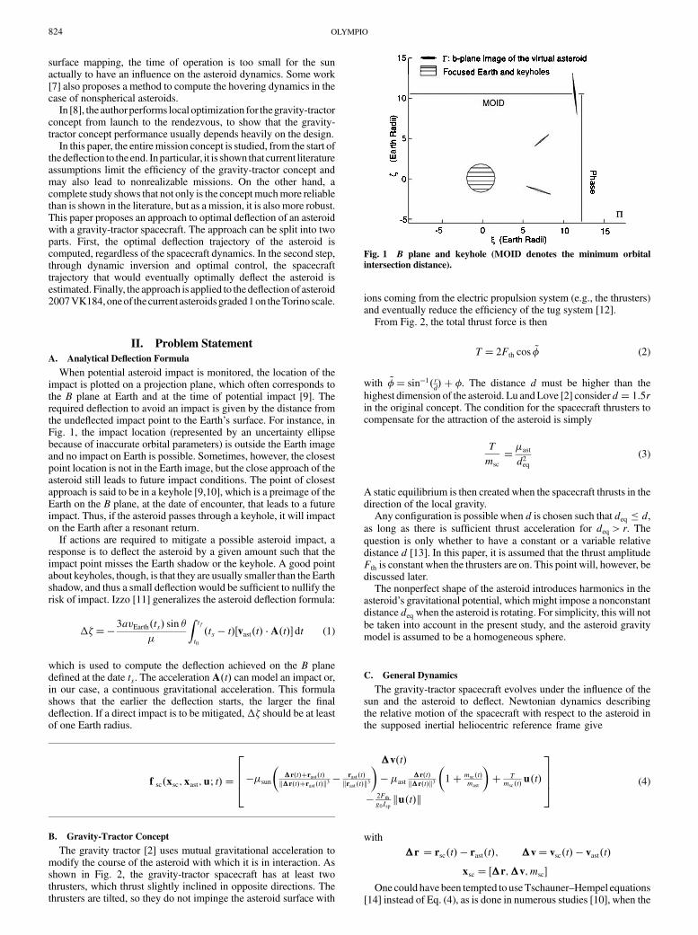
Fig. 3 Optimal and nonoptimal fully thrusting deflection with a gravity-tractor spacecraft (wrt denotes with respect to).
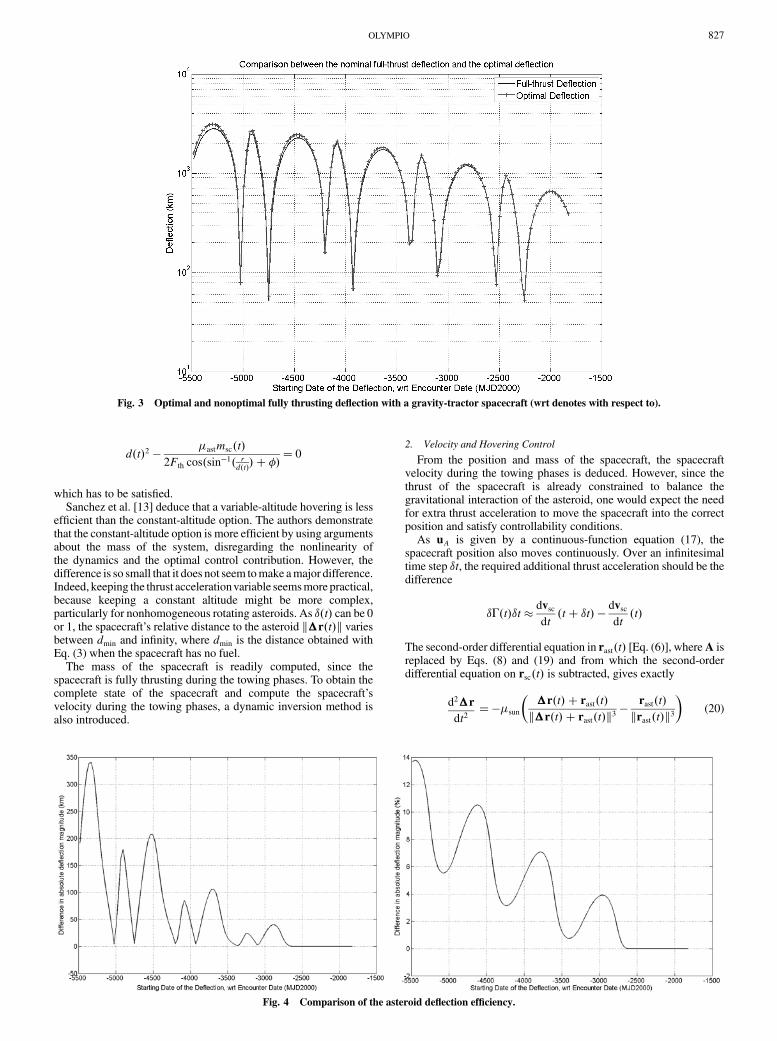
Fig. 4 Comparison of the asteroid deflection efficiency.
OLYMPIO 827

which is equivalent to Eq. (4) using the equilibrium-conditionequation (3) [in a towing phase and supposingmsc mast in Eq. (4),the terms relative to the thrust acceleration and themutual gravitationvanish]. In otherwords, ��� 0.Mathematically, it shows that anyC2
functions uA�t� satisfy the second-order differential equation in�rthrough the equilibrium-condition equation (19) and the mutualgravitational acceleration. In addition, the regularity of uA�t� isassured by the maximum principle [17], since the solution nevercrosses the switching curve during towing phases. Physically, thisindeed confirms that the entire system that is accelerated and noadditional thrust acceleration is required.
To compute vsc�t�, a collocation method [15] is used. Discretizingthe time-interval into nodes ftig, and knowing the spacecraft position�r�ti� and mass msc�ti� at each node, Eq. (4) has a unique solutionfor each segment [ti, ti�1] and �t0; tf�. Obviously, as the solution
�r�t� of Eq. (4) is at leastC2 [because of Eq. (19) and because uA�t�is at least C2], �v�t� is at least C1, and thus the relative velocity�v�ti� is also continuous at each node: �v�t�i � ��v�t�i �. Thus,�vi is sought to satisfy the defect �i:
8>>><>>>:�v�ti� ��vi
d�vdt���sun
��r�t��rast�t�k�r�t��rast�t�k3
� rast�t�krast�t�k3
��i ��r�ti�1� ��r�ti� �
R ti�1ti �v�t� dt
(21)
These problems are boundary-value problems that are readily solvednumerically by a shooting algorithm [20] or by a multiple-shootingmethod to solve all the ��i at once [21].
Fig. 5 Asteroid nominal and deflected trajectory (TOF denotes time of flight).
Fig. 6 Asteroid optimal deflection phases (control amplitude uA).
828 OLYMPIO
B. Spacecraft Trajectory During Nontowing Phases
1. Possible Strategies
During nontugging phases, the dynamic interaction between thespacecraft and the asteroid is limited to the mutual gravitation.According to Eq. (19), the spacecraft must be at infinite relativedistance from the asteroidwhen not tugging. Placing the spacecraft atan infinite distance from the asteroid is equivalent to placing thespacecraft at a relative distance
dSOI � a��ast
�sun
�2=5
(22)
which corresponds to the asteroid sphere of influence (SOI) radius[22]. Then the spacecraft has to perform escaping maneuvers. Thisanalysis comes from the equilibrium relation equation (3); however,a close look at the dynamics gives us another option. Indeed, if thespacecraft simply stops thrusting and is placed on an orbit around theasteroid, the tugging effect does not exist either.
Because of the dynamics and the very small relative velocity of theasteroid, if the spacecraft stops thrusting, it would be on a highly
eccentric orbit around the asteroid and would simply crash onto it.The spacecraft has to increase its thrust levelT, either with additionalthrusters or by reducing the cant angle � toward zero, and correct itscurrent orbit eccentricity.
2. Dynamics
The asteroid is assumed to be a homogeneous sphere. Morecomplex shapes will be considered in future work, although someinformation can be found in thework of Kawaguchi et al. [23] for theJapan Aerospace Exploration Agency mission Hayabusa.
As in [4,5], the dynamic equation (4) is used. For simplification,�ast �sun is assumed, and since the spacecraft is evolving in thesphere of influence of the asteroid, the term relative to the sungravitational acceleration can be neglected.
3. Solution Method
As a strategy, the spacecraft goes in minimum time on a circularparking orbit of radius dref around the asteroid and then goes back inminimum time into a hovering state. Consider t1 and t2 (respectively,
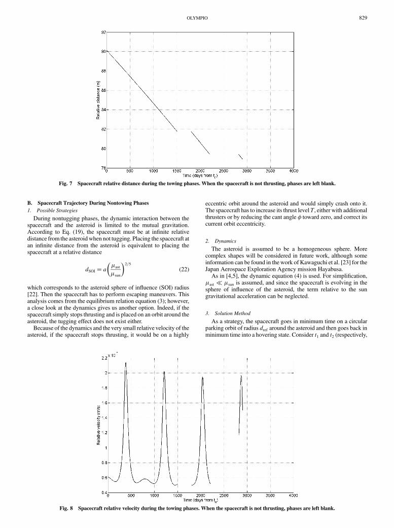
Fig. 7 Spacecraft relative distance during the towing phases. When the spacecraft is not thrusting, phases are left blank.
Fig. 8 Spacecraft relative velocity during the towing phases. When the spacecraft is not thrusting, phases are left blank.
OLYMPIO 829

the start and the end of the nontowing phase) and ti1 and ti2 (respec-
tively, the dates when the spacecraft reaches and leaves, the circularorbit). Variables t1 and t2 are given, whereas ti1, and t
i2 are free
parameters because of the minimum-time problems. The constraintsfor the intermediate states at ti1 and t
i2 are given by
k�r�ti1�k � dref � 0 (23)
E� �
2dref� 0 (24)
�r �ti1�T�v�ti1� � 0 (25)
with the energy of the osculating orbit defined as
E� k�v�ti1�k22
� �ast
k�r�ti1�k
and for the terminal state,
�r �t2� ��r2 (26)
�v �t2� ��v2 (27)
The first constraint imposes the point of injection at a given distancedref , the second constraint forces the energy to be that of an ellipticorbit of semimajor axis dref , and the third constraint imposes thecircularity of the orbit. The last two constraints determine the state ofthe spacecraft for hovering. This state ��r2;�v2� is determined bymeans of the inversion method described in Sec. IV.A. The state ofthe spacecraft at ti2 is readily available because the spacecraft is on thecircular orbit between ti1 and t
i2.
An equivalent problem can be formulated when the spacecraftgoes back to the thrusting deflection state. The spacecraft on itscircular orbit must reach a given state near the asteroid.
An optimal control problem is solved by the formulation of twoseparate TPBVPs. The optimality conditions are given by
d�T
dt���T @fs
@x(28)
u �� �v
k�vk(29)
and the transversality conditions for each problem are given by
��Tr �ti1�;�Tv �ti1��T � �1@E
@��r;�v� � �2@k�rk@��r;�v� � �3
@�rT�v
@��r;�v�(30)
�H�ti1� � 1� �1@E
@t1� �2
@k�rk@t1
� �3@�rT�v
t1(31)
with �1, �2, and �3 Lagrange scalars assigned to the constraints, and
H�ti2� � 1 (32)
The problem is solved using optimal control and a shooting method.The spacecraft would need to thrust to change its velocity. Despite
an almost null initial relative velocity, the velocity change required toreach such an orbit is likely to be very small because of the smallgravitational constant of the asteroid.
It is likely, however, that performing the change of orbit can bemore efficiently achieved by the use of chemical thrusters. Thevelocity change is so small, however, that having another propulsionsystem on boardmight not be interesting from a design point of view.
Fig. 9 Spacecraft thrust cant angle during the towing phases. When the spacecraft is not thrusting, phases are left blank.
Fig. 10 Spacecraft trajectory in the asteroid frame during towing
phases.
830 OLYMPIO
V. Application: Optimal Deflection of 2007 VK184
The approach is applied to the deflection of asteroid 2007 VK184.This asteroid belongs to the Apollo family and is thus an Earthcrossing near-Earth object. It has been selected because it currentlybelongs to the set of asteroids [24] graded 1 or higher on the Torinoscale [25] with a nonzero impact probability. Grade 1 on the Torinoscale basically means that careful attention is needed, as an impact ispossible. This asteroid may eventually be downgraded to level zero(no risk) when further observations are available. Our choice is moreacademic and is not supposed to represent any futuremission. Table 1gives the main properties of the asteroid,† such as its orbit around thesun at the given epoch, and its mass.
The spacecraft is equipped with two NSTARXenon engines, witha specific impulse Isp ranging from 1900 to 3100 s and a thrust forceFth from 92 to 19 mN for the lowest input power. To have anequilibrium distance of 90 m and �� 66 deg, the thrust force foreach thruster should be 50 mN. If Isp � 2500 s, the initial spacecraftwet mass is m0 � 1500 kg and the spacecraft dry mass ismf � 800 kg. The initialmass and the drymass are chosen so that thecumulated thrust time does not exceed six years (it is currently thelongest-duration experiment to date with an ion engine [19]),although the mission itself can exceed this duration. The date andtime are explained in Table 2. The mission start date is deduced fromthe potential impact date and the warning time.
Figures 3 and 4 depict the difference in deflection between thefully thrusting deflection scenario and the optimal thrustingdeflection scenario. Data for the fully thrusting deflection scenarioswere computed from thework of Izzo [11].When the time of flight tothe potential impact date was too short to spend all the fuel, the fullythrusting strategy was chosen for both scenarios. Figure 3 depicts thedeflection achieved for every encounter date. The shorter theremaining time to an encounter, the less the achieved deflection, inaccordance with the results in [11].
Figure 4 shows the difference in deflection between the optimaldeflection and the fully thrusting deflection. The difference in thedeflection between the two strategies reaches about 100 km (about6%of relative deflectionmagnitude) if the spacecraft starts deflectingthe asteroid 10 years before the foreseen impact date. This differencemight not be important, although in the worst case, the performanceachieved is equal to the one obtained in the fully thrusting case, but
including coast phases, which can be used for any operationalconcerns. For prekeyhole deflection, an order of magnitude of100 km on the deflection is often sufficient. Some points toward theend of the graph either did not converge or the difference wasextremely small and tolerance was not tight enough to improve it. Sothere are no improvements toward the end of the graph, despite thegeneral trend of the oscillations. The difference can be much higherfor asteroids with an initial high-eccentricity orbit. The curves areoscillating with a pseudoperiod, which is about one asteroid orbitalperiod (828 days). The modulation is due to the term (ts � t) inEq. (1).
For the sake of illustration, the point that presents 100 km indeflection is selected. Figure 5 plots the trajectory of the asteroidbeing deflected.
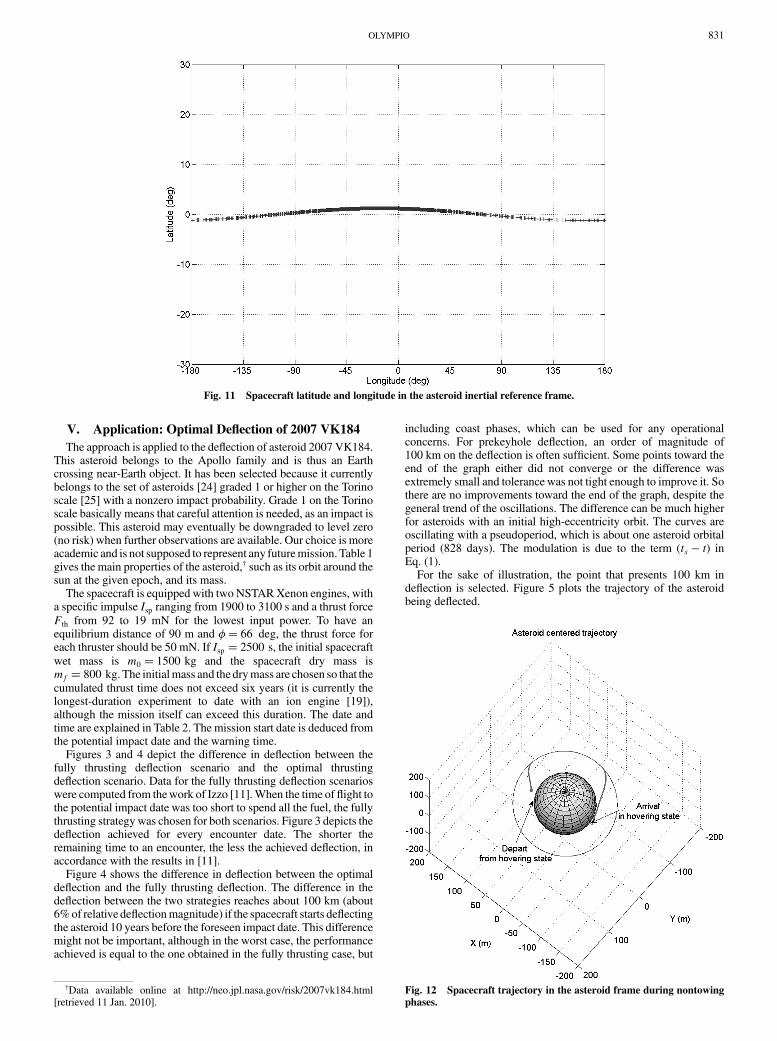
Fig. 11 Spacecraft latitude and longitude in the asteroid inertial reference frame.
Fig. 12 Spacecraft trajectory in the asteroid frame during nontowing
phases.
†Data available online at http://neo.jpl.nasa.gov/risk/2007vk184.html[retrieved 11 Jan. 2010].
OLYMPIO 831

Figure 5 depicts the deflected and nondeflected asteroidtrajectories, and the deflection is so small that the difference inposition is not visible at this scale. The arrows represent the directionof the perturbative acceleration induced by the gravity tractor. Thisdirection is mostly tangential to the orbit, or parallel to the velocityvector, in accordance with Eq. (17). In fact, far from the potentialimpact date ts, the perturbative acceleration induced by the spacecraftis collinear to the system’s heliocentric velocity. The amplitude of theperturbation control uA is plotted in Fig. 6; it shows three coastphases and three thrust phases.
Figures 7–9 depict the relative distance between the spacecraft andthe asteroid, the relative velocity, and the cant angle. Clearly, becauseof the hovering, the relative velocity is small and almost zero. Thecant-angle graph shows that when the spacecraft gets closer to theasteroid surface, the cant angle widens.
Figure 10 shows the equivalent relative trajectory. The distancevariations come from the loss in mass during thrusting, making theequilibrium distance decrease. Even though the trajectory makesmany revolutions around the asteroid, this motion is actually a slowmotion, where the period is about one sidereal period of the asteroidaround the sun.
Figure 11 shows that the spacecraft stays relatively close to theasteroid orbital plane. This means that the mutual acceleration doesnot go out of the ecliptic plane for this case, which is in accordancewith the optimization.
Figure 12 describes the maneuver for an a orbit of 110 m of radiusfrom the hovering position and the maneuver for going from thecircular orbit to the new hovering position. Table 3 summarizes theboundary conditions. In contrast with Fig. 10, the motion is a rapidmotion, where the period is the orbital period around the asteroid(41 min). The total transfer time is sufficiently small to notsignificantly change the mass budget of the spacecraft.
VI. Conclusions
A two-stage method to compute the gravity-tractor trajectory andoptimal control deflection of an asteroid is presented. Simplifieddynamicmodels of the asteroid and the spacecraft are used for towingand nontowing phases. The solar radiation pressure is neglected, andthe asteroid is assumed to be a homogeneous sphere. The commonassumptionwhereby an asteroid is continuously towed by the gravitytractor is discussed and determined to be nonoptimal. Optimal coastphases can provide slight improvements in the deflection.
The difference in scale between the spacecraft dynamics aroundthe asteroid and the asteroid dynamics around the sun requires goodprecision. The method allows both dynamics to be independentlycomputed. Therefore, since the computation of the deflectionachieved is insensitive to the spacecraft dynamics, numerical cal-culations are accurate and reliable.
In the application case, the deflection of a near-Earth objectis considered. The optimal deflection improves the nonoptimaldeflection by a few hundred kilometers, which is sufficient forprekeyhole deflection. It is very likely that the difference betweenoptimal and fully thrusting deflection is higher for asteroids withhighly eccentric orbits. Furthermore, the control includes coastperiods, which, from an operational point of view, allows time forrecovering for any operational failures. Thus, the optimal deflectionof an asteroid allows an improvement in both the deflection and therobustness.
References
[1] Ahrens, T., and Harris, A., “Deflection and Fragmentation of Near-Earth Asteroids,” Nature, Vol. 360, No. 6403, 1992, pp. 429–433.doi:10.1038/360429a0
[2] Lu, E., and Love, S., “Gravitational Tractor for Towing Asteroids,”Nature, Vol. 438, No. 7065, 2005, pp. 177–178.doi:10.1038/438177a
[3] Fahnestock, E., and Scheeres, D., “Dynamical Characterization andStabilization of Large Gravity-Tractor Designs,” Journal of Guidance,Control, and Dynamics, Vol. 31, No. 3, 2008, pp. 501–521.doi:10.2514/1.32554
[4] Wie, B., “Dynamics and Control of Gravity Tractor Spacecraft forAsteroid Detection,” Journal of Guidance, Control, and Dynamics,Vol. 31, No. 5, 2008, pp. 1413–1423.doi:10.2514/1.32735
[5] McInnes, C., “Near Earth Object Orbit Modification UsingGravitational Coupling,” Journal of Guidance, Control, andDynamics,Vol. 30, No. 3, 2007, pp. 870–873.doi:10.2514/1.25864
[6] Broschart, S., and Scheeres, D., “Control of Hovering Spacecraft NearSmall Bodies: Application to Asteroid 25143 Itokawa,” Journal of
Guidance, Control, and Dynamics, Vol. 28, No. 2, 2005, pp. 343–354.doi:10.2514/1.3890
[7] Gehler, M., Ober-Blobaum, S., Dachwald, B., and Marsden, J.,“Optimal Control of Gravity Tractor Spacecraft Near ArbitrarilyShaped Asteroids,” 1st IAA Planetary Defense Conference, Granada,Spain, 27–30 April 2009.
[8] Izzo, D., Olympio, J., and Yam, C., “Asteroid Deflection Theory:Fundamentals of Orbital Mechanics and Optimal Control,” 1st IAA
Planetary Defense Conference, Granada, Spain, 27–30 April 2009.[9] Valsecchi, G. B., Milani, A., Gronchi, G. F., and Chesley, S. R.,
“Resonant Returns to Close Approaches: Analytical Theory,”Astronomy and Astrophysics, Vol. 408, No. 3, 2003, pp. 1179–1196.doi:10.1051/0004-6361:20031039
[10] Yeomans, D., Bhaskaran, S., Broschart, S., Chesley, S., Chodas P.,Jones, M., and Sweetser, T., “Near-Earth Object (NEO) Analysis ofTransponder Tracking and Gravity Tractor Performance,” JetPropulsion Lab., California Inst. of Technology, Task Plan No. 82-120022, Pasadena, CA, Sept. 2008.
[11] Izzo, D., “Optimization of Interplanetary Trajectories for Impulsive andContinuous Asteroid Deflection,” Journal of Guidance, Control, andDynamics, Vol. 30, No. 2, 2007, pp. 401–408.doi:10.2514/1.21685
[12] Schweickart, R., Chapman, C., Durda, D., and Hut, P., “ThreatMitigation: The Gravity Tractor,” B612 Foundation, White Paper 042,Sonoma, CA, June 2006
[13] Sanchez, P., Colombo, C., Vasile, M., and Radice, G., “MulticriteriaComparison Among SeveralMitigation Strategies for Dangerous Near-Earth Objects,” Journal of Guidance, Control, and Dynamics, Vol. 32,No. 1, 2009, pp. 121–142.doi:10.2514/1.36774
[14] Tschauner, J., and Hempel, P., “Rendezvous with a Target in EllipticOrbit,” Astronautica Acta, Vol. 11, No. 5, 1965, pp. 104–109.
[15] Betts, J., “Survey of Numerical Methods for Trajectory Optimization,”Journal of Guidance, Control, and Dynamics, Vol. 21, No. 2, 1998,pp. 193–207.doi:10.2514/2.4231
[16] Broschart, S., and Scheeres, D., “Boundedness of Spacecraft HoveringUnder Dead-Band Control in Time-Invariant Systems,” Journal of
Guidance, Control, and Dynamics, Vol. 30, No. 2, 2007, pp. 601–610.doi:10.2514/1.20179
[17] Pontryagin, L. S., Boltyanskii, V. G., Gamkrelidze, R. V., andMishchenko, E., The Mathematical Theory of Optimal Processes,Interscience Publishers, New York, 1962, Chap. 1.
[18] Bertrand, R., and Epenoy, R., “New Smoothing Techniques for SolvingBang-Bang Optimal Control Problems—Numerical Results andStatistical Interpretation,” Optimal Control Applications and Methods,
Table 3 State at the beginning and end of the first non-thrust-deflecting phase,
computed by the inversion dynamic method
First nontowing phase
Dates (from t0) 1508.5 days 1804.3 daysPosition �r, m � 72:596 21:997 1:36 � � �31:823 68:841 �1:057 �Velocity �v (10�5 m=s) � �0:137 0:459 0 � � �0:416 �0:209 �0:017 �Mass msc 969.6 kg
832 OLYMPIO

Vol. 23, No. 4, 2002, pp. 171–197.doi:10.1002/oca.709
[19] Rayman, M., Fraschetti, T., Raymond, C., and Russell, T., “Dawn: AMission in Development for Exploration of Main Belt Asteroids Vestaand Ceres,” Acta Astronautica, Vol. 58, No. 11, 2006, pp. 605–616.doi:10.1016/j.actaastro.2006.01.014
[20] Keller, H., Numerical Methods for Two-Point Boundary-Value
Problems, Dover, New York, 1992, pp. 7–18.[21] Kierzenka, J., and Shampine, L., “A BVP Solver Based on Residual
Control and the MATLAB PSE,” ACM Transactions on Mathematical
Software, Vol. 27, No. 3, 2001, pp. 299–316.doi:10.1145/502800.502801
[22] Battin, R., An Introduction to the Mathematics and Methods of
Astrodynamics, Rev. ed., AIAA Education Series, AIAA, Reston, VA,1999.
[23] Kawaguchi, J., Fujiwara, A., and Uesugi, T., “Hayabusa—ItsTechnology and Science Accomplishment Summary and Hayabusa-2,”Acta Astronautica, Vol. 62, Nos. 10–11, 2008, pp. 639–647.doi:10.1016/j.actaastro.2008.01.028
[24] Yeomans, D., and Baalke, R., “Sentry Risk Table,” May 2009, http://neo.jpl.nasa.gov/risks/index.html [retrieved 11 Jan. 2010].
[25] Binzel, R. P., “The Torino Impact Hazard Scale,” Planetary and SpaceScience, Vol. 48, No. 4, 2000, pp. 297–303.doi:10.1016/S0032-0633(00)00006-4
OLYMPIO 833