optical wavelength laboratories - owl-inc. · pdf fileoptical wavelength laboratories...
TRANSCRIPT

Optical Wavelength Laboratories
OPERATIONS GUIDE
PON-2M PON POWER METERModel Number:
PON-2M
OWL-INC.COM
Revision 1.00 Optical Wavelength Laboratories (OWL)N9623 West US Hwy 12
Whitewater, WI 53190Phone: 262-473-0643
Internet: OWL-INC.COM
OWL
i
INTRODUCTION
TABLE OF CONTENTS
SECTION 1: INTRODUCTIONBefore You Begin . . . . . . . . . . . . . . . . . . . . . . . . . . . . . 1About This Manual . . . . . . . . . . . . . . . . . . . . . . . . . . . . 1Applications. . . . . . . . . . . . . . . . . . . . . . . . . . . . . . . . 2Description . . . . . . . . . . . . . . . . . . . . . . . . . . . . . . . . 2Precautions . . . . . . . . . . . . . . . . . . . . . . . . . . . . . . . . 3
Safety . . . . . . . . . . . . . . . . . . . . . . . . . . . . . . . . . 3Operational . . . . . . . . . . . . . . . . . . . . . . . . . . . . . . . 3Connector . . . . . . . . . . . . . . . . . . . . . . . . . . . . . . . 3
Product Label . . . . . . . . . . . . . . . . . . . . . . . . . . . . . . . 3General Features . . . . . . . . . . . . . . . . . . . . . . . . . . . . . 4Display Features. . . . . . . . . . . . . . . . . . . . . . . . . . . . . . 5
SECTION 2: OPERATIONPower ON/OFF . . . . . . . . . . . . . . . . . . . . . . . . . . . . . . 6Backlight . . . . . . . . . . . . . . . . . . . . . . . . . . . . . . . . . 6Battery Status . . . . . . . . . . . . . . . . . . . . . . . . . . . . . . . 7Battery Charging . . . . . . . . . . . . . . . . . . . . . . . . . . . . . 7
Set Thresholds . . . . . . . . . . . . . . . . . . . . . . . . . . . . . . 8PASS/FAIL/WARNING Measurement. . . . . . . . . . . . . . . . . . . . 9Optical Power Measurement . . . . . . . . . . . . . . . . . . . . . . . . 10Set/View Reference.. . . . . . . . . . . . . . . . . . . . . . . . . . . . 11Save/View Stored Data . . . . . . . . . . . . . . . . . . . . . . . . . . 12
SECTION 4: MAINTENANCEReplacing the Batteries. . . . . . . . . . . . . . . . . . . . . . . . . . . 13Cleaning the Optical Ports . . . . . . . . . . . . . . . . . . . . . . . . . 14Specifications . . . . . . . . . . . . . . . . . . . . . . . . . . . . . . . 15Maintenance and Calibration Information . . . . . . . . . . . . . . . . . . 15Contact Information . . . . . . . . . . . . . . . . . . . . . . . . . . . . 15
SECTION 3: TEST PROCEDURES

1
INTRODUCTION
BEFORE YOU BEGIN
All personnel testing optical fibers should be adequately trained in the field of fiber optics before using any fiber optic test equipment.
If the user is not completely familiar with testing fiber optics, they should seek competent training. Such training can be acquired from a variety of sources, such as local hands-on training classes.
Valuable information about fiber optic testing can also be gathered from reading printed literature carefully or by thoroughly reading supplied operations manuals.
Fiber optic testers vary from other types of test equipment due to issues such as:
1) standards-based testing2) proper fiber optic test procedures (FOTPs)3) "zeroing" or referencing of power levels4) determining the correct link budget to pass or fail by
Complete understanding of each of these issues is critical for performing proper fiber optic tests.
Throughout this manual you will find various symbols that assist with understanding the procedures outlined in this manual. Below is a list of these symbols and a short description of their purpose:
Shows a helpful tip that will make a procedure go more smoothly
Tells the user some useful information about the successful completion of a procedure
Warns the operator of a potentially dangerous condition
ABOUT THIS MANUAL

2
INTRODUCTION
APPLICATIONS
Below is a list of test and measurement applications that can be performed using the PON-2M PON (passive optical network) power meter. The procedure for each one of these applications is covered in detail in this manual.
PON Optical Power Measurements. FTTH networks should be measured to ensure that the power levels received from the ONT (optical network terminal) and OLT (optical line terminal) are sufficient for accurate and reliable transmission.
Active Equipment Optical Power Measurements. Active equipment should be measured periodically for correct power levels. The transmitters in this equipment have a known power value. The PON-2M can be directly attached to this equipment via a patch cord to check whether the transmitter is within the manufacturer’s specified power range.
Fiber Continuity Testing. Continuity can be measured with the PON-2M by placing a calibrated light source on one end of the fiber and the PON-2M on the other end. This is also a simple way to measure the attenuation of the fiber.
This manual describes the operation of the PON-2M PON power meter.
The PON-2M is a very economical option for measuring the output power of ONT and OLT in FTTx PON networks. The PON-2M is NIST traceable, and is calibrated 1310, 1490, and 1550nm. Up to 10 threshold levels can be set for different measurement points on the FTTH network.
Its user-friendly interface includes nine push-buttons to cover all the functions of the PON-2M. Up to 100 readings can be stored in internal memory, which can be retrieved on the LCD display at a later time.
The PON-2M includes two SC connectors – one for connection to OLT and one for connection to the ONT. An internal pass-through allows for all three FTTx wavelengths to be measured simultaneously when the network is in operation.
The PON-2M is powered by (3) AAA batteries, which allows for 36 hours of battery life.
At additional cost, a model is available that allows data to be downloaded via USB to a PC in Excel spreadsheet format using download software.
DESCRIPTION

3
INTRODUCTION
PRECAUTIONS
Safety - Exercise caution when working with any optical equipment. High-intensity fiber optic laser sources output potentially dangerous high energy invisible light, and could cause serious, irreparable damage to the eye. Thus, it is recommended to look into the connector port of a light source or the end of a fiber.
Operational - It is important to keep connector ferrules and optical connector ports clean. If dirt, dust, and oil are allowed to build up inside connector ports, irreparable damage may occur to the optics inside the port. For best results, replace dust caps after each use.
Connector - Do NOT insert APC (Angled Physical Contact) connectors into the SC ports on the .
NEVER
PON-2M
On the back of each PON-2M PON power meter is a label similar to the one shown below containing model number, serial number, and power requirements.
PRODUCT LABEL
MODEL# PON-2MSERIAL# PM13000POWER: 9V DC

GENERAL FEATURES
4
INTRODUCTION
1 ONT connector SC connector; measures upstream signal (1310nm) coming from ONT
2 OLT connector SC connector; measures downstream signals (1490 and/or 1550nm) coming from OLT
3 LCD display Displays power levels, power units, wavelength, and battery status
4 ONT status LED Displays the “Pass/Warning/Fail” status of upstream signal (1310nm) based upon the selected threshold
5 OLT status LED Displays the “Pass/Warning/Fail” status of downstream data signal (1490nm) based upon the selected threshold
6 Video status LED Displays the “Pass/Warning/Fail” status of downstream video signal (1550nm) based upon the selected threshold
7 Power button Press once to power ON or OFF; hold for 2 seconds while power ON to cancel auto shutoff
8 F/P button Toggle between “optical power mode” and “Pass/Warning/Fail mode”
9 Backlight button Toggle backlight on and off
10 Units button Display units in dBm, dB, or µW
11 Threshold set button Set “Pass/Warning/Fail” thresholds; up to 10 thresholds can be set
12 Save button Save currently displayed power reading for each wavelength
13 REF button Displays optical reference level for each wavelength
14 USB port Downloads stored data (for models that support data download)
15 Charger port With AC/DC charger, charges batteries
16 Battery charger LED Displays the status of the battery charger
DO NOT USE BATTERY CHARGING PORT WITH NON-RECHARGEABLE BATTERIES.
THERE IS THE POTENTIAL FOR EXPLOSION AND DAMAGE MAY OCCUR TO THE UNIT AND/OR THE USER.
US
B
Sta
te
9V
1A
14
15
16
DISPLAY FEATURES
5
INTRODUCTION
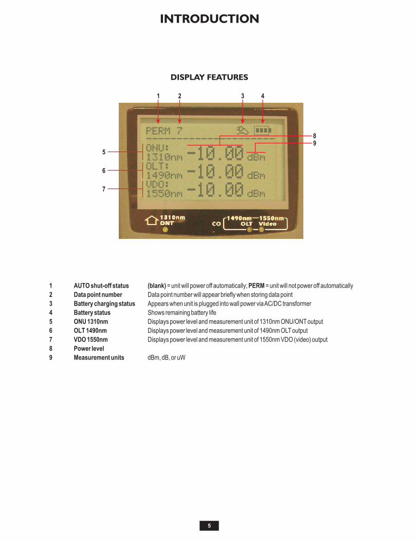
1 AUTO shut-off status (blank) = unit will power off automatically; PERM = unit will not power off automatically
2 Data point number Data point number will appear briefly when storing data point
3 Battery charging status Appears when unit is plugged into wall power via AC/DC transformer
4 Battery status Shows remaining battery life
5 ONU 1310nm Displays power level and measurement unit of 1310nm ONU/ONT output
6 OLT 1490nm Displays power level and measurement unit of 1490nm OLT output
7 VDO 1550nm Displays power level and measurement unit of 1550nm VDO (video) output
8 Power level
9 Measurement units dBm, dB, or uW
PERM---------------------
ONU:
1310nm
OLT:
VDO:
1490nm
1550nm
-10 00x
7
-10 00x
-10 00x
dBm
dBm
dBm

6
OPERATION
The POWER button serves three purposes:
Power ON with auto-shutoff enabledPress power button once.
Unit will power off automatically after 10 minutes of inactivity.
Power ON with auto-shutoff disabledHold power button for two (2) seconds.
“PERM” will appear in the upper left hand corner of the display. Unit will only power off when pressing the power button again.
Power OFFPress power button once.
POWER ON/OFF
PERM---------------------
ONU:
1310nm
OLT:
VDO:
1490nm
1550nm
LO
LO
LO
Press the BACKLIGHT button to toggle the backlight on or off.
BACKLIGHT
PERM---------------------
ONU:
1310nm
OLT:
VDO:
1490nm
1550nm
LO
LO
LO
PERM---------------------
ONU:
1310nm
OLT:
VDO:
1490nm
1550nm
LO
LO
LO
BACKLIGHT OFF
BACKLIGHT ON
7
OPERATION
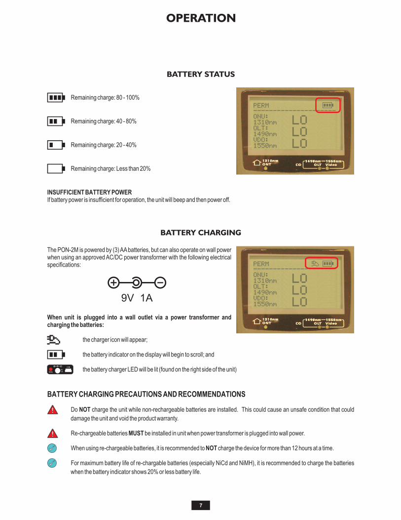
Remaining charge: 80 - 100%
Remaining charge: 40 - 80%
Remaining charge: 20 - 40%
Remaining charge: Less than 20%
INSUFFICIENT BATTERY POWERIf battery power is insufficient for operation, the unit will beep and then power off.
BATTERY STATUS
PERM---------------------
ONU:
1310nm
OLT:
VDO:
1490nm
1550nm
LO
LO
LO
The PON-2M is powered by (3) AA batteries, but can also operate on wall power when using an approved AC/DC power transformer with the following electrical specifications:
When unit is plugged into a wall outlet via a power transformer and charging the batteries:
the charger icon will appear;
the battery indicator on the display will begin to scroll; and
the battery charger LED will be lit (found on the right side of the unit)
BATTERY CHARGING PRECAUTIONS AND RECOMMENDATIONS
Do NOT charge the unit while non-rechargeable batteries are installed. This could cause an unsafe condition that could
damage the unit and void the product warranty.
Re-chargeable batteries MUST be installed in unit when power transformer is plugged into wall power.
When using re-chargeable batteries, it is recommended to NOT charge the device for more than 12 hours at a time.
For maximum battery life of re-chargable batteries (especially NiCd and NiMH), it is recommended to charge the batteries
when the battery indicator shows 20% or less battery life.
USB
State
9V1A
BATTERY CHARGING
PERM---------------------
ONU:
1310nm
OLT:
VDO:
1490nm
1550nm
LO
LO
LO9V 1A

Attaching the PON meter to a different point in the PON network will require a different set of thresholds for power measurements of PON wavelengths. It is important to set thresholds in the PON meter so that it can show PASS/FAIL/WARNING results.
Up to 10 different threshold sets can be configured in the PON -2M PON power meter.
SET THRESHOLDS
Press the THRESHOLD button to enter the menu for setting PON thresholds.
DISPLAY
1 Threshold Set Number Value: 1 - 102 Wavelength 1310, 1490, or 1550nm3 Upper FAIL Threshold Power levels above this value will be
reported as FAIL4 Warning Threshold Power levels below this value will be reported as a warning (WRNG)5 Lower FAIL Threshold Power levels below this value will be reported as FAIL
BUTTONS
6 UP arrow key Moves cursor to previous menu option
While option is selected: inc reases th resho ld power value
7 DOWN arrow key Moves cursor to next menu option
While option is selected: decreases threshold power value
8 ENTER key When Threshold Set Number is highlighted: toggles through the set numbers
While a threshold power value is highlighted: moves cursor to next column of threshold power value
When finished setting thresholds, ensure that the desired threshold set number is selected, then press THRESHOLD twice to exit.
After exiting the SET THRESHOLD screen, do NOT change any of the calibration values on the “Calibration”
screen that appears. Changing these calibration values will cause the device to lose its NIST calibration.
Press THRESHOLD to exit the “Calibration” screen.
8
TEST PROCEDURES
SET THRESHOLDS
Threshold 1490nm----xxUnit:dBm FALT: 3 0xxx XX X
No:XXX XXXX X1 WRNG:-20 0
XXXXXXXXXXX XFALT:-30 0
1310nm---- 1550nm----X
WRNG:-20 0 WRNG:-20 0X X X
FALT: 3 0XX X XFALT: 3 0XX X
FALT:-30 0 FALT:-30 0X X X

Connecting the PON power meter to the FTTx network
PASS power level falls between the upper FAIL and Warn ing threshold levels
WRNG power level falls between the and lower FAIL
threshold levels
FAIL power level is either above the upper FAIL threshold or below the lower FAIL threshold
Interpreting PASS/FAIL/WRNG results
Before viewing PON power measurements in PASS/FAIL/WRNG mode, ensure the proper threshold values have been set
and selected. See the “SET THRESHOLDS” section for more information.
To view results according to the selected threshold, it may be necessary to press the F/P button so that the words
PASS/FAIL/WRNG appear next to the PON power levels.
Warn ing
9
TEST PROCEDURES
PASS/FAIL/WRNG MEASUREMENT
Measures upstreamsignals coming fromcustomer equipment
(ONT: 1310nm)
ONT Measures downstreamsignals coming from
CO/head-end equipment(OLT: 1490 / VDO:1550nm)
OLT
---------------------
ONU: WRNGxxxxxxxxxxxxx
1310nmXXXXXXXXXXdBm
OLT:xxxxxxxxxxxxxPASS
VDO:xxxxxxxxxxxxxFAIL
1490nmXXXXXXXXXXdBm
1550nmXXXXXXXXXXdBm
-24 72x
-12 37x
+ 3 47x x

10
TEST PROCEDURES
OPTICAL POWER MEASUREMENT
Connecting the PON power meter to the FTTx network
Optical Power Measurement
In Optical Power mode, the PON meter
does not compare opt ical power measurements to any specific threshold.
To view results in Optical Power mode, it
may be necessary to press the F/P button so that PASS/FAIL/WRNG are not displayed, and
Optical power can be displayed in dBm, dB, or microwatt (uW) measurement units. Press the dBm/dB button to display until the desired measurement unit appears on the display.
the indicator LEDs are not lit.
To view optical power in dB units, an optical
reference must first be set for all wavelengths. See the “SET/VIEW REFERENCE” section for instructions.
Measures upstreamsignals coming fromcustomer equipment
(ONT: 1310nm)
ONT Measures downstreamsignals coming from
CO/head-end equipment(OLT: 1490 / VDO:1550nm)
OLT
---------------------
ONU:
1310nmXXXXXXXXXXdBm
OLT:
VDO:
1490nmXXXXXXXXXXdBm
1550nmXXXXXXXXXXdBm
-24 72x
-12 37x
+ 3 47x x

11
TEST PROCEDURES
SET/VIEW REFERENCE
Connecting the PON power meter to the FTTx network
Set Reference
To view optical power in dB measurement units, an optical reference must be set for each wavelength.
To set an optical reference, a light source must first be connected for whatever wavelength(s) need to be set. Up to 3 wavelength references can be set simultaneously.
Press and hold the REF/Enter button for 2 seconds to set a reference for every wavelength that is currently connected to the PON meter. The display will automatically switch to dB measurement units.
View Reference
Press the REF/Enter button once to briefly view the currently set reference levels for each wavelength.
Measures upstreamsignals coming fromcustomer equipment
(ONT: 1310nm)
ONT Measures downstreamsignals coming from
CO/head-end equipment(OLT: 1490 / VDO:1550nm)
OLT
---------------------
ONU:
1310nmXXXXXXXXXXdB
OLT:
VDO:
1490nmXXXXXXXXXXdB
1550nmXXXXXXXXXXdB
- 0 270 x
- 0 731 x
+ 0 74x x

Up to 100 test readings can be stored in the PON-2M PON power meter.
SAVE DATA
Press and hold the SAVE/RECALL button to store data for the current fiber under test. The stored reading will include power data for all three wavelengths.
As the data is being saved in memory, the data point number will briefly appear at the top of the display.
RECALL STORED DATA
To view stored data, press the SAVE/RECALL button. Five readings will be shown on the display at a time.
Press the DOWN button to view the next five readings.
Press the UP button to view the previous five readings.
12
TEST PROCEDURES
SAVE/VIEW STORED DATA
---------------------
ONU:
1310nmXXXXXXXXXXdBm
OLT:
VDO:
1490nmXXXXXXXXXXdBm
1550nmXXXXXXXXXXdBm
-24 72x
-12 37x
+ 3 47x x
PERMX7
xxxxx xx xx1310 1490 1550
01 -31 7 - 6 2 -27 5xx x x x x x x
02 -32 0 -13 1 - 3 1xx x x x x xX
03 NONE NONE NONExXx xX xX
05 NONE NONE NONExXx xX xX
04 NONE NONE NONExXx xX xX
<-Prev Next->xxxxxxxxx
History

The battery compartment is covered by a clip-on plate on the back of the unit. Three (3) AA batteries are required for operation.
Pull back on battery cover locking tab.
Lift off battery cover.
Replace (3) AA batteries.
13
MAINTENANCE
REPLACING THE BATTERIES

MAINTENANCE
CLEANING THE OPTICAL PORTS
Required Accessories:
= Isopropyl alcohol (91% or better)= In-adapter fiber optic cleaning accessories, such as 2.5mm cleaning swabs or other in-adapter ferrule connector cleaner.=Fiber optic inspection probe (LCD-based, 200x magnification or greater recommended)=Compressed Air (optional)
Below are procedures for “wet” cleaning and “dry” cleaning. For best results, a combination of these cleaning methods is recommended.
14
“WET” CLEAN PROCEDURE
Wet the tip of a 2.5mm cleaning swab with isopropyl
alcohol.
Carefully insert the wet tip of the swab into the optical
port.
Clean out the optical port according to the directions
provided with the swabs.
Blow dry the optical port with the compressed air. If
compressed air is not available, allow 2 minutes for the alcohol to evaporate.
Inspect the optical port with the fiber optic inspection
probe to ensure the port is clear of obstructions.
If the port is still dirty, another round of cleaning will be necessary. You may also want to use a combination of “wet” and “dry” cleaning to achieve best results.
“DRY” CLEAN PROCEDURE
Carefully insert a dry 2.5mm cleaning swab or a
2.5mm in-adapter ferrule connector cleaner into the optical port.
Clean out the optical port according to the directions
that came with the cleaning accessories.
Inspect the optical port with the fiber optic inspection
probe to ensure the port is clear of obstructions.
If the port is still dirty, another round of cleaning will be necessary. You may also want to use a combination of “wet” and “dry” cleaning to achieve best results.

15
MAINTENANCE
SPECIFICATIONS
Batteries. This unit ships with non-rechargeable alkaline batteries installed. If re-chargeable batteries are required, the user must purchase their own re-chargeable batteries and battery charger.
Storage. When not in use, store the device in a dry, well-ventilated place. Remove the batteries if the device will not be in use for a long period.
Calibration. It is recommended to have Optical Wavelength Laboratories calibrate this unit once per year.
Warranty. The Silicon ZOOM 2 comes standard with a two-year factory warranty, which covers manufacturer defect and workmanship only.
CONTACT INFORMATION
MAINTENANCE AND CALIBRATION INFORMATION
Address: Phone: Internet:
Optical Wavelength Laboratories, Inc. 262-473-0643 OWL-INC.COMN9623 US Hwy 12Whitewater, WI 53190
Measurement Range 1310: +10 to -35 dBm
1490: +10 to -50 dBm
1550: +25 to -45 dBm
ORL 35 dB
Pass-through Insertion Loss < 1.5 dB
Accuracy ±0.5 dB (burst signal)
±0.2 dB
Threshold Sets 10
Data Storage 100
Connectors SC/PC
Auto Power Off Yes
Battery Charge Yes
Operation Time ~36 hours
Storage Temperature -20 to +60° C
Operating Temperature -10 to +50° C
Operating/Storage Humidity 90% relative
Power Supply (3) AAA batteries or
AC adapter
Size 7.48” x 3.54” x 1.57”
Weight ~1 pound