optical tolerances for alignment and image … · acceptable rang2. this means that optical...
TRANSCRIPT

AAMELI-TY 43619
OPTICAL TOLERANCES FOR ALIGNMENT AND IMAGE DIFERENCESFOR BINOCULAR KELMET-MOUNTED DISPLAYS
HERS•CHEL, C. S;'J1F
ARMSTRONG AEROSPACE MEDICAL RESEARCH LABORATORY
DTIC;.Y1986 ^ ELECTE
• NOV 2 8 9886
A
CL.) Approved for public release; distribution is unlimited.
1HARRYG. ARMSTRONG AEROSPACE MEDICAL RESEARCH LABORA7DRYAEROSPACE MEDICAL DIVISIONAIR FORCE SYSTEMS COMMANDWRIGHT PATTERSONAIR FORCE BASE, OHIO 45433-6573
86 11 28 0067l %

r'
UNCLASSIFIED4 SECU1RITY CLASSIFICATION OF THIS PAGE
REPORI DOCUMENTATIO PAGEILr. REPORT SECURITY CLASSIFICATION It. RESTRICTIVE MAPKING5
UNCLASS IFIED7, SECURITY CLAS5IFICAT1QN AUTHORITY UTION/AVAt LAB' ý.ITY OF REPORT
Approved for public release; distribution2b. OECLASSIF•:ICATION/DOWNGRAD'IIG SCHFO.DULE is unlimited.
4 PERFORMING ORGANIZATION REPO'-T K--NMBEH(S) 5. MONITORING ORGANIZATION REPORT NUMBER(S)
AAMRL-TR-86- 0196i . NAME OF PERFORMING ORbANIZATION 1'. OFFICE SYMBOL 7a. NAME OF MONITORING ORGANIZATION
Harry G. Armstrong Aerospace | Itapplicable)
Medical Research Labc'atory AAMRL/HEA
6c. ADORES. WCity. State and ZIP COL%.. 7b. ADDRESS (City. State and ZIP Code)
Wright-Patterson AFB OH 45433-6573
S NAME OF FUNDING/SPCNSORING 8b. OFFICE SYMBOL 9. PROCUREMENT INSTRUMENT IDENTIFICATION NUMBERORGANIZATION (It applicable)
Sc. ADDRESS (City. State and ZIP Code) 10. SOURCE OF FUNDING NOS.
PROGRAM PROJECT I-ASK WORK UNITELEMENT NO. NO. NO. NO.
11. TITLE (Include Security Ceuir•caton OPTICAL TOLERANCES 62202F 7184 ii 46
FOR ALIGNMENT AND IMAGE DIFFERENCES fOR BINOCILAR HELMET-M)UNTED DIS LAYS12. PERSONAL AUTHOR(S)
Self, Herschel C.13& TYPE OF REPORT 1Ib. TIME COVERED 14. DATE OF REPORT (Yr.. Mo.. Day) 15. PAGE COUNT
PROM ____TO ___Technica] =1RO. 1ol986 MayI
16. SUPPLEMENTARY NOTATION
17. COSATI CODES lB. SUBJECT TERMS (Continue on reuers. if necesory and identify by block number)
FIELD GROUP S.. . GR. Helmet Mcunted Binocular DisplaysOptical Alignment£01 1 -imatnn Tnranr.
.ASTRACT (Continu, on neuers, it necesuary and identify by bloc; number)
[F Reviews the literature on optical aiignment and image difference tolerances fori. binocular devices. Tolerances for verifieal and horizontal misalignment and for
rotation, magnification and luminance differences are recommended. Recommendationsare made for collimation tolerance and for eye relief and exit pupil diameter forhelmet-mounted binocular displays. Formulas are derived for magnificationdifference tolerances for partially and totally overlapping fields of view.
F -7
20. DISTRIBUTION/AVAILABIL1-Y OF ABSTRACT 21. ABSTRACT'SECURITY CLASSIFI.
UNCLASSIFIED/UNLIMITe3 [@ SAME AS APT. CO DTIC USERS C3 UNCLASSIFIED22& NAME OF RESPONS.BLL" (iIDIVIDLIAL 22b. TELEPHONE NUMBER '22c. OFFICE SYMBOL
(Include Area Code)Herschel C. Self (513) 255-8895 I AAMRL/HEA
DD FORM 1473, 83 APR EDITION OF 1 JAN 73 IS OBSOLLTE.
SECURITY CLASSIFICATION OF THIS PAGE
PRE FACE
This report was prepared for project number 7184, Program Element62202F, and Work Unit 71841146. The work was done during the periodNovember 1984 to January 1985.
Thonks are due to Dr. Thomas Furness and to Mr. Charles Bates, long-tima supporters and pritoe movers of helmet-mounted display technology, fortheir- encouragement and support. Special acknowledgement is due to Mr.Wayne Martin for his careful reading of the rough draft of the document andhi nuamerous suggentions for improvement, and to Miss Tanya Ellifritt fortyping and secretarial support.
VNT7ISGRA&IoDTIC TABJU-tif~lcationL-=--=-
By-_Distribution/______
Availability Codes
tAvail and/or
Dist Special
S142
IWII • •I

Table of Contents
Page
Purpose . . . . . . . . . . . . . . . . . . . . . . . . . . . . . . . . . 5
Introduction . . . . . . . . . . . . . . . . . . . . . . . . .. . . . . . 5
Literature Survey . . . . . . . . . . . . . . . . . . . . . . . . . . .
Comments on the Literature Survey and Discussion .. . . . .. . 11
Summary of Discussion ............................ ........... 14
Effect of Field Overlap on Tolerances for Rotation and MagnificationDifferences in the Two Fields of View . . . . . . . . . . . . . . . . . 15
Recommended Ranges and Tolerances for the Adjustment and Alignment ofBinocular Helmet-Mounted Displays . . . . . . . . . . . . . . . . . .. 16
1. IPD Adjustment Range . . . . . . . . . . .... ....... . . 16
2. IPD Adjustment Effects on Alignment . . . . . . . . . . . . .. 16
3. Tolerance for Vertical Misalignment . . . . . . . . . . . . . . 16
4. Tolerance for Horizontal Misalignment . . . . . . . . . . . . . 17
5. Tolerance for Rotation Difference . ..... .............. . 17
6. Tolerance for Magnification Difference ..... ............. 18
7. Tolerance for Luminous Difference . . . . . . . . . . . . . . . 20
8. Collimation Tolerance . . . . . . . . . ................... . 21
9. Eye Relief . . . . . . . . . . . . . . ....... . . . . . . . . 22
10. Exit Pupil......... ....... . . . . . . . . . . . . . . . . 22
Eye Versus Instrument Tolerances...... ... ..... ... ..... . . . . . 23
Appendix A: Permissible Rotation Difference .... .......... 24
Appendix B: Magnification Difference Tolerance for CompletelyOverlapping Fields of View . . . . . . . . . . . . . . 28
Appendix C: Magnification Difference Tolerance Formulas forPartially Overlapping Fields of View . . . . . . . . . 29
References . . . . . . . . . . . . . . . . . . . . . . . . ......... 34
2
List of Illustrations
Page
Figure 1. Geoimietry for Vertical Misalignment Due to RelativeRotation . . . . . . . . . . . . . . . . . . . . . . . . . . . 26
Figure 2. Alternative Derivation for Formula for RotationDifference Tolerance Formula...... . . . . . . . . . . .27
Figure 3. Geometric Relationships for Partially-Overlapping Fields ofView Where Overlap is Less Than 50%, i.e., Less Than F/2 . . . 30 H
3:3z

List of Tables
Page
Table 1. Definitions of Alignment Errors and OpticalImage Differences . . . . . . . . . . . . . . . . . . . . . .. 6
Table 2. Some Tolerance Limits for Binocular InstrumentsCited in Technical Literature . . . . . . . . . . . . . . . . . 13
Table 3. Maximum Rotation Difference, Tolerance forBinocular HMD Fields of View with 100% Overlapnot Exceeding Permissible Vertical Misalignment . . . . . . . . 19
Table 4. Maximum Permissible Magnification Difference forA Binocular HMD with Completely Overlapping FOVs ....... 21
Table 5. Maximum Image Height in Overlapping or Common Area . . . . . . 31
4

Optical Tolerances for Alignment and ImageDifferences for Binocular Helmet-Mounted Displays
PURPOSE
This document has three objectives: (1) to apply the findings ofresearch in optics and vision as well as current optical practice to thespecification of optical tolerances for binocular helmet-mounted displays(HMDs), (2) to serve as an introduction to, and tutorial on, opticaltolerance limits for image differences and optical alignment of binocularHMDs, and (3) to formulate a set of optical tolerance limit specificationsuseful for specifying, purchasing, inspecting, testing, and adjustingbinocular liMOs.
For several years the Human Engineering Division of AAMRL at Wright-Patterson Air Force Base, Ohio has been the Air Force center for thedevelopment of head-up helmet-mounted displays (HMD). Recently, theDivision has been developing the technology for binocular HMDs, and has thefirst such device, one fabricated for research purposes. Essential to thedevelopment and application of such binocular devices is the generation ofspecifications for the optical characteristics required for human use bymembers of the Armed Forces in real missions.
Since binocular HMDs represent a brand new technology, required opticalcharacteristics have not been documented. The author, therefore, examined
the scientific and technical literature for human factors data relevant tothe alignment and adjustment of binocular helmet-mounted HUDs. Other staffmembers are researching required luminance and color characteristics.
The present document reviews relevant literature, discusses tolerancesand adjustments in a tutorial manner and presents tentative recommendationsfor adjustments and tolerances.
INTRODUCTION
In a binocular helmet-mounted display (HMD) there a-e two images, onefor each eye. The two images may differ in several ways, and bothhorizontal and vertical ;:ignment error may be present at the same time.Alignment errors refer to lack of parallelism of the two optical axes.Table 1 lists and defines types of alignment errors and optical imagedifferences.
Zero optical image differences and zero alignment errors are notpossible with binocular devices. A very close approach to perfection isquite expensive in dollars and in equipment weight and volume. Fortunately,near perfection is not necessary: some imperfection can be present withoutill effects.
With a well-adjusted binocular device, such as & binocular HMD, anobserver fuses the two images into one so rapidly that he never notices that
5
r
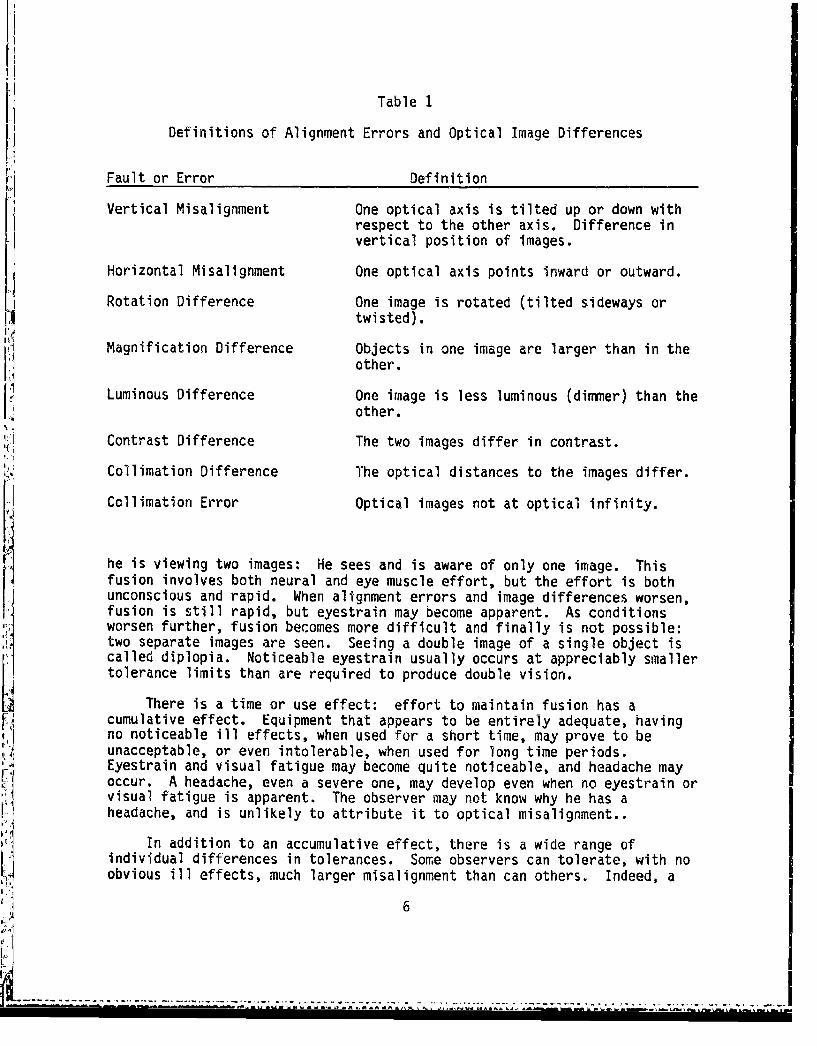
Table 1
Definitions of Alignment Errors and Optical Image Differences
Fault or Error Definition
Vertical Misalignment One optical axis is tilted up or down withrespect to the other axis. Difference invertical position of images.
Horizontal Misalignment One optical axis points inward or outward.
Rotation Difference One image is rotated (tilted sideways ortwisted).
Magnification Difference Objects in one image are larger than in theother.
Luminous Difference One image is less luminous (dimmer) than theother.
Contrast Difference The two images differ in contrast.
Collimation Difference The optical distances to the images differ.
Collimation Error Optical images not at optical infinity.
he is viewing two images: He sees and is aware of only one image. Thisfusion involves both neural and eye muscle effort, but the effort is bothunconscious and rapid. When alignment errors and image differences worsen,fusion is still rapid, but eyestrain may become apparent. As conditionsworsen further, fusion becomes more difficult and finally is not possible:two separate images are seen. Seeing a double image of a single object iscalled diplopia. Noticeable eyestrain usually occurs at appreciably smallertolerance limits than are required to produce double vision.
There is a time or use effect: effort to maintain fusion has acumulative effect. Equipment that appears to be entirely adequate, havingno noticeable ill effects, when used for a short time, may prove to beunacceptable, or even intolerable, when used for long time periods.Eyestrain and visual fatigue may become quite noticeable, and headache mayoccur. A headache, even a severe one, may develop even when no eyestrain orvisual fatigue is apparent. The observer may not know why he has aheadache, and is unlikely to attribute it to optical misalignment..
In addition to an accumulative effect, there is a wide range ofindividual differences in tolerances. Some observers can tolerate, with noobvious ill effects, much larger misalignment than can others. Indeed, a
6
....................-..... .

dp-ree of alignment error unnoticed by, or even undetectable by, one
observer may be unacceptable to another.
Zero optical alignment tolerances and zero tolerances for imagedifferences are not practical: they would be difficult and expensive toobtain and could riot be retained in use. Practical tolerances permit almostall observers to function, over extended use intervals, with negligible lossin visual capabilities and without eyestrain, visual fatigue, or developmentof a headache. Because of the large individual differences in observertolerance to misalignment and image differences, and because ill effects arenot always immediately apparent, a quick visual inspection is not adequatefor determining if alignment errors and image differences are within anacceptable rang2. This means that Optical Tolerance Limits, usually calledtolerances, must be specified with numbers and individual instrument errorsand image differences must be measured to be sure that every HMD is withinall tolerance limits.
As previously noted, overly strict or stringent tolerancespecifications cause equipment to be overly expensive, yet not detectablybetter, in either comfort or capability, than devices with somewhat I rgertolerance limits. At the other extreme, overly loose or liberal tolerancesresult in equipment that is unsatisfactory for some users and unusable bysome. Practical specifications are, and must be, a compromise. One levelof compromise that is widely used in equipment procurement is to settolerances so that 95 percent of all users are accommodated with little orno loss in comfort or capability. Unfortunately, research data is notavailable to permit such tolerance specifications for HMD optics. There aresome data sources, but usually not enough people were used as test observersto establish tolerance limits that will include any given percentage of HMDusers.
Binocular instruments, such as binoculars, field glasses, binoculartelescopes, and binocular microscopes have been used for scores of years.Experience accumulated with these instruments, together with some limitedscientific research, has resulted in what might be called current opticalpractice. Some of the tolerances used in current practice have unknownorigins. Some is based on what, at some time or other, was judged as beingsensible and reasonable.
LITERATURE SURVEY
Jacobs (1943) discusses the optics of misalignment in binoculars Histolerance formulas give the maximum amount of permissible misalignment as afunction of optical magnification. The formulas indicate that the eyesshould not have to diverge by more than 7.5 arc minutes, converge by morethan 22.5 minutes, or have to tolerate over 8 minutes of verticalmisalignment. He does not say where he obtains his numerical values,although he lists some pre-1932 references at the end of the chapter onbinoculars and battery-commander telescopes (a form of telebinocular).
:! .. . . .

During World War II the University of Texas reviewed, for the Office ofNaval Research, literature that could be related to the designspecifications of hand-held binoculars to be used visually. Using thisliterature review, in June of 1946 the Army-Navy-National Research Council
ti recommended that vertical misalignment of binoculars should not exceed 14arc minutes, observers should not have to converge their eyes more than 28minutes of arc or diverge them more than 14 minutes. How the visioncommittee arrived at the numerical values that they recommended is notreported. They do say, however, that the recommendations are not fouidedupon a firm basis and they recommend that psychophysical experimentationshould be done. The committee recommendations on alignment is one of theurtauthored papers reported by Harvey (197%, particularly page 312).
Ingalls and Pestrecov (1948) discuss, for engineers and scientists, thecentering or alignment of optical systems. Their concern is with aligningthe optical elements in one optical path, rather than with the alignment oftwo optical paths, and they give no values for tolerances. They arementioned because, as a classic on alignment, their article is often quotedby other authors in discussion of binocular instruments.
Johnson (1960) says that observers differ in tolerance to alignmenterror, but that "the results of a large number of tests seem to indicatethat, for a normal person, the safe limit to impose on the induced angle ofaccommodation is 20 18' (4 prism diopters) horizontal convergence, 10 9' (2prism diopters) horizontal divergence and 34.5' (1 prism diopter) ofvertical vergence". He gives no references or supporting data.
MIL-Handbook-141 (1962), the military standardization handbook onoptical design, on page 17 of section 4, says that a difference inmagnification in the two sides of a binocular instrument causes an apparentdistortion of space. It says that a difference in magnification of 1 or 2percent or more usually results in visual strain and discomfort and thatdifferences of 5% usually preclude binocular vision. Some people, itstates, cannot tolerate more than .5%, while others may tolerate a littlemore than 2%. It recommends that magnification differences should notexceed 2%. Further, the amount of light to the two eyes should differ byless than 10%, while vertical misalignment should not exceed .5 prismdiopter (17 arc minutes), and a maximum value of .33 diopter (11 arcminutes) difference may be desirable. Any twist (or rotation difference)should be kept to a minimum. No references are given for any of therecommiended tolerances.
The U.S. Navy training course textbook, "Optical man 3 & 2" (1966) hasa section (page 470) on tolerance and performance requirements for U.S. Navybinoculars. In this section it says that the optical axes of the twobarrels must be parallel within 2 arc minutes vertically, within 4 minutesdivergence, and within 2 minutes convergence. It says that failure of thedistance scale readings must be accurate within 1 millimeter to prevent
eyestrain. To avoid a blurred image and eyestrain, the two diopter (orfocus) scales for the eyepieces must be accurate within 1/4 diopter. The
8

light transmission of the two barrels may not differ by more than 3 percent.No references or supporting data are given.
Gold and Hyman (1970) experimentally determined visual requirements for
head-up displays. They investigated both exit pupil size and binocularmisalignment. To examine misalignment, they developed a laboratorytelecentric optical viewing system. Subjects viewed dynamic images throughthe optics against a static view of a real-worlc background. The backgroundwas an aerial view of real terrain, including a few buildings. Viewingtimes were 15 seconds, which they said were adequate for indicating comfortin real flight. In each 15 secornd presentation, observers judged visualcomfort level on a scale ranging from 1 (excellent) to 6 (image doublingmore than 50% of the time). Three observirs were used.
They found that when a real-world background was used, as compared to ahomogeneous background, the maximum permissible angular misalignments weremuch smaller, by as much as a factor of 10. Their criteria of adequatevisual comfort for sustained viewing requires much smaller angularmisalignments than those at which image doubling (diplopia) occurs. Theyfound that vertical misalignment should not exceed 1 milliradian (3.4minutes of arc), and that, also, the eyes should not have to tolerate morethan 1 milliradian of divergence. Comfort in extended viewing, in addition,requires that horizontal convergence should not exceed 2.5 milliradians (8.6minutes of arc).
Gold (1971) did a second study to obtain alignment tolerances for head-up displays (HUDs). He used an optical system that provided symbols from aCRT superimposed on terrain imagery provided, via a beamsplitter, by 16 mnmotion picture imagery collected at low altitude. He thus simulated viewingsymbols through a HUD with a dynamic (moving) real-world background. Thefield of view was quite narrow: 12.5 degrees for both eyes with a 6 degreeoverlap. Each test run was followed by observers rating the run on a 6-point visual comfort scale. Data is reported for 4 observers. Disparitiesmuch smaller than those that produce image doubling (diplopia) causedcomplaints of visual stress and annoyance. Test condition differences weresmaller than test result differences between observers. Individualobservers differed by a large and statistically significant amount inmisalignment tolerances. In terms of allowable angular misalignment,tolerances were much smaller (smaller angles) when disparities were viewedagainst a real-world background than when viewed against a homogeneousbackground. From examination of his data, Gold concluded that vertical[' misalignment should not exceed 1 milliradian (3.4 arc minutes), convergence
should not exceed 2.5 mr (8.6 minutes), and divergence should not exceed 1mr (3.4 minutes). His results with a dynamic back round were essentiallythe same as those obtained by Gold and Hyman (1970) when static real-worldbackgrounds were used.
Gibson (1980) performed three experiments with head-up displays in
which both an outside world scene and symbols (a winged aircraft andhorizontal bars) were viewed. The head-up display was not helmet-mounted.
9IAdý X dlOb d*PV fn kw w%' WA'I

Negative disparity between world scene and symbols was slowly increaseduntil the onset of visual discomfort or unease. The mean negative disparityfor unease or discomfort was .83 mrad, i.e., when the HUD symbology was .83mrad behind the target. The range for 10 subjects was +.10 to -1.06 mrad.To find at what distance the symbology should be projected, a secondexperiment with a simulated weapon-aiming situation was simulated. The same10 subjects adjusted the display for optimum viewing of both the aimingcircle and the target in the outside world. The mean setting was +.72 mrad,so that the optimum viewing position was a positive disparity of .38 mrad,i.e., aiming circle between the observer and the target. Nine of 10subjects set the display to a positive disparity. A third experiment wasdone to determine the point at which subjects could perceive a parallaxbetween the HUD imagery and the outside world. The mean threshold for the 8subjects used was .23 mrad. The results of Gibson's study is that whensymbols appear in a head-up display, negative disparity (symbols behind thescene) should not be present, and that the optimum viewing position ofsymbology is in front of the scene with a positive disparity of .38 mrad.
MIL-Standard-1472C (1981), "Military Standard orn Human EngineeringDesign Criteria for Military Systems, Equipment, and Facilities", has asection (page 211) on binoculars and bioculars. It says: "binocular/biocular instruments should have an eyepiece separation scaled from 50 to 73millimeters with one millimeter interval markings ... " "magnificationdifferences of the two barrels should not exceed 2% ... " "luminoustransmission differences in the two barrels should not exceed 5%". Nosupporting data or references are given, and no alignment tolerances arespecified.
Binocular head-up displays (HUDs) may be used by observers in vehicleswhose windscreens or canopies produce optical disparities. For example,they may be used in an aircraft whose thick curved windscreen causes lightrays from a distant poiait in the environment to be bent or deviated bydifferent amounts for the two eyes of the observer. It has been found that,with some aircraft windscreens, light rays from a distant point in theenvironment appear to come from a point as near as 40 feet away from theSobserver. When collimated images from a sensor are presented to an observerby a binocular HUD, the directly-viewed environment seen through such a
windscreen and the HUD-presented image will not appear to be at the samedistance. When the distance between them is appreciable, looking at eitherone of them produces double images (diplopia) of the other one.
"Because of Air Force pilot complaints of double vision with a wide-field-of-view HUD, Genco (1983) measured diplopia thresholds. He used 32non-pilot volunteers whose vision was measured and found to meet at leastFlying Class 2 Vision standards. Observers fixated a distant object, a lamppost, and reported whether or not a briefly-presented distant luminous lineappeared single or double. They also reported if a single line appeared,but was misaligned with the target, which would indicate suppression ofvision in one eye. Four thresholds were determined by a bracketingtechnique for each observer: one at each crossing of two disparitydirections (positive and negative) with two exposure times for each (.1
10

second and 3 seconds). It was found that: (1) observers were relativelyintolerant of negative disparity, (2) very short glances were less likelythan longer viewing to produce double vlson, (3) individuals variedconsiderably in resistance to double vision, and (4) a large oortion ofresponses involved suppression of vision from one eye. Because thedistributions of threshold values were strongly skewed, rather thansymmetrical, median scores, rather than means, were reported. Medians arevalLes above and below which half of the scores fall. The overall mediannegative disparity threshold for double vision was 1.2 milliradian (4.1 arcminutes), and the overall positive threshold was 2.6 mrad (8.8 arc minutes).Thus, half of the observers had vision problems at those disparity values.Gencn recommended 4.1 arc minutes of eye divergence and 8.8 arc minutes ofeye convergence as the maximum misalignments acceptable for wide FOV head-updisplay systems combined with cockpit canopies. It is of some interest thatGenco's recommendations for convergence and divergence tolerances areessentially the same as those of Gold and Hyman (1970) and Gold (1971) wholimited convergence to 8.6 arc minutes and divergence to 3.4 arc minutes.
CO"IENTS ON LITERATURE SURVEY AND DISCUSSION
A search of the technical literature for tolerances for satisfactoryhuman use of binocular devices revealed that frequently, indeed usually, noresearch data, or any other supporting data, was cited. For example, therecommendations given in Military Standard 1472C (1981) and in MilitaryHandbook 141 (1962) are presented without references or supporting data.Even optics textbooks usually present recommended tolerances withoutsupporting them.
Since binocular helmet-mounted displays are a brand new technology, nodata on tolerances derived from their use or from tests done with them hasbeen collected. However, they are a form of head-up display (HUD), and HUDshave been around for some time, particularly for cockpit use in aircraft asdiscussed earlier. Gold (1971) and Gold and Hyman (1970) conducted researchto obtain alignment tolerance data for HUDs. However, Gold's data is fromonly 4 satisfactory subjects, hardly representative of any population. Goldand Hyman (1970) used only 3 observers. Both studies obtained essentially[I the same results.
Examination of the technical literature, in addition to revealing thesmall number of tested observers used in almost all relevant research, alsorevealed large differences in the tolerance limits cited by the differentauthors. A large part of the difference between authors is undoubtedly dueto their use of different criteria for deciding what is tolerable. Forexample, visual comfort criteria of acceptability yield much smaller(tighter) tolerances than do image fusion criteria, i.e., avoidance ofdouble vision. Gold (1971) noted that observers complained of visual stressand annoyance caused by amounts of misalignment that were considerablysmaller than those that produce image doubling. A second reason for authordifferences is their sampling of different populations of observers.Related to this is the very large differences in tolerances of individualobservers. With only a few observers, this large observer difference is
, 11
14

kI
likely to yield a nonrepresentative sample of observers. Nonrepresentativesamples from different populations would not be expected to yield verysimilar test results.
Finally, and possibly of most importance, investigators who usedcomplex scenes, such as real world pictures, obtain results that can differby a large amount from results obtained with uniform backgrounds or with fewimage details. Results can differ by as much as a factor of ten. Gold andHyman (1970) and Gold (1971) note that disparity tolerances weresignificantly lower (tighter) when images were viewed against a simulatedreal-world background, compared to a homogeneous visual background. Thus,when a complex background is present, permissible differences between theright and left images were smaller. To avoid confusion it appears that useof the terms "tighter" or "more stringent" would be preferable, in atolerance context, to use of "increase". Also, "looser" or "less stringent"may be preferable to "larger".
The rather large differences in recommendations for tolerance limits
cited in the literature are apparent from an examination of the data inTable 2. In view of the preceding paragraph, the large differences are notsurprising. The optical tolerance limits that are recommended in thepresent paper are given in a later section.
It is apparent that some of the tolerance values in Table 2 are givento 3 significant digits, implying an accuracy of better than 1%. Thesemulti-digit values were sometimes obtained by converting from one or twodigit values originally in different measurement units. An example is prismdiopters converted to arc minutes. For example No. 4, Johnson, lists 34.5arc minutes tolerance for vertical misalignment tolerance, a value obtainedfrom 1 prism diopter that he reconmends, or 20 18' for convergence, which is4 prism diopters. Johnson did note that his recommendations were in prismdiopters and arc minutes. The point is made because much of the publisheddata was collected using standard optometry equipment with 1/4 dioptermeasurement steps. Original test data, then, often has a measurementaccuracy no better than about 10%, and is sometimes worse. The fact thatmeasurement intervals may be large, plus the subjective nature of themeasurements and the very large differences in tolerances between differentobservers indicate that is it mis~eading to cite tolerances beyond twodigits.
A second interesting thing about the data in Table 2 is the rathersmall values for convergence tolerances of the eyes. Tolerances are quitesmall relative to how much nearly everyone can converge his eyes. Humaneyes easily converge by an angle exceeding 160. However, convergence inwhich the visual axis of the eyes do not intersect at even approximately theoptical distance to the image involves noncorresponding retinal points andwill result in considerable effort to fuse the two images on the tworetinae. The attempt to fuse images may fail, resulting in double vision,diplopia, at easily-achieved eye convergence angles.
12

Table 2
Some Tolerance Limits for BinocularInstruments Cited in Technical Literature
No. Author/Source Vertical Misalignment Convergence Divergence
1 MIL-STD 1472C (1981) Not Given Not Given Not Given
2 Farrell & Booth (1984) 10' 2.70 0
3 Jacobs (1943) 8' 22.5' 7.5'
4 Johnson (1948) 1 P.D.*=34.5' 4 P.D.=20 18' 2 P.D.=1o 9'
5 MIL-HDBK-141 (1962) ½ P.D. = 17'
6 Gold and Hyman (1970) 1 M.R.=3.4' 2.5 M.R.=8.5' 1 M.R.=3.4'
7 Gold 1 M.R.**=3.4' 2.5 M.R.=8.61 1 M.R.=3.4'
8 NRC Vision Committee (1946) 14' 28' 14'
9 Genco (1983) Diplopia Medians: 8.8' 4.1'
Luminance Difference: No. 2: < 50%, Preferably < 25%, No. 6: < 10%.
Magnification Difference: No. 1: &.5%; No. 2: Not producing over 10' verticalmisalignment, 1o8% for 400 FOV; No. 5: 4-2%,some can't tolerate more than .5%. J. Enoch(in No. 2):.25 - .5 percent cause visualdiscomfort.
Rotation Difference: No. 2: Not producing more than 10' of verticalmisalignment, not >.50 for a 400 FOV;No. 4: "... rotation difference can not be tolerated";No. 6: "keep it to a minimum".
* I P.D. = 1 prism diopter = an angle whose tangent is .01 = .5730 = .01radian = 34.5'.
** 1M.R. = 1 milliradian = .05730 = 3.44 arc minutes = .1 P.D.
13
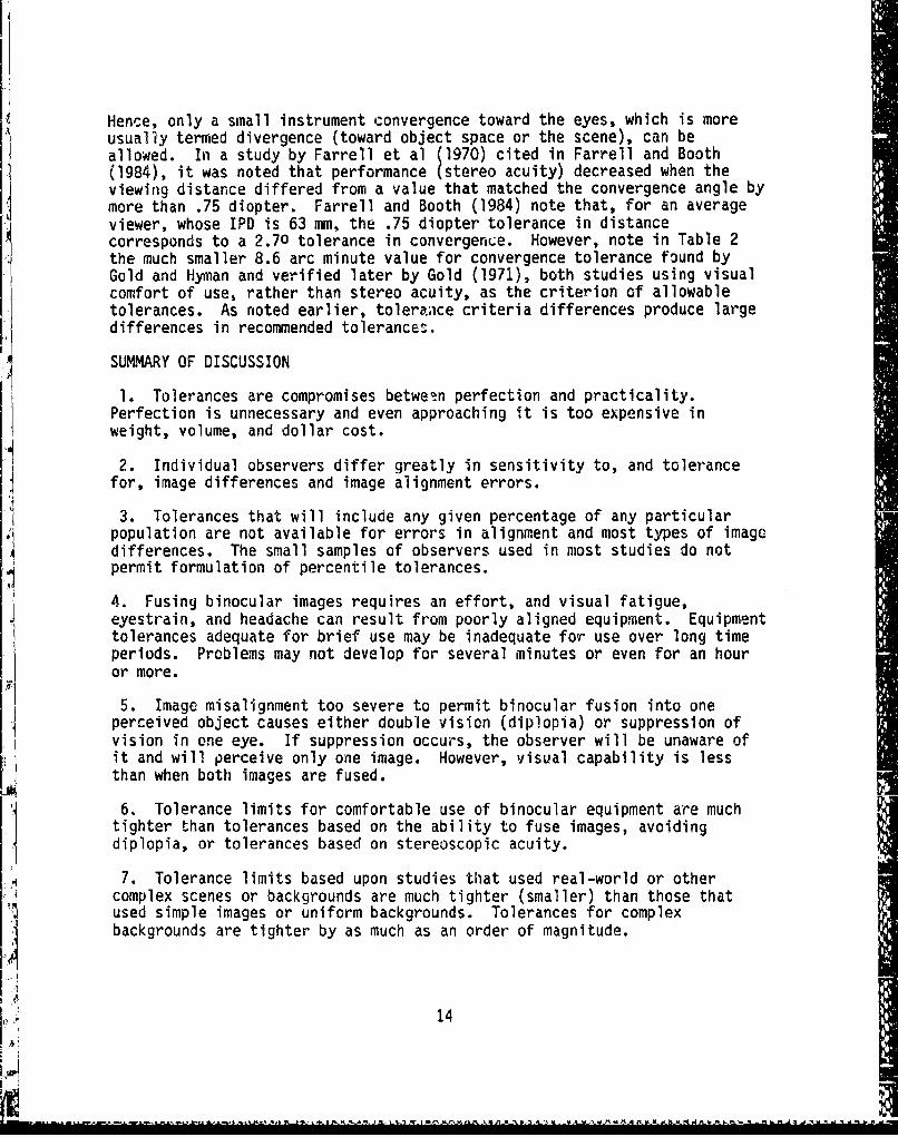
Hence, only a small instrument convergence toward the eyes, which is moreusually termed divergence (toward object space or the scene), can beallowed. In a study by Farrell et al (1970) cited in Farrell and Booth(1984), it was noted that performance (stereo acuity) decreased when theviewing distance differed from a value that matched the convergence angle bymore than .75 diopter. Farrell and Booth (1984) note that, for an averageviewer, whose IPD is 63 mm, the .75 diopter tolerance in distancecorresponds to a 2.70 tolerance in convergence. However, note in Table 2the much smaller 8.6 arc minute value for convergence tolerance found byGold and Hyman and verified later by Gold (1971), both studies using visualcomfort of use, rather than stereo acuity, as the criterion of allowabletolerances. As noted earlier, toleranice criteria differences produce largedifferences in recommended tolerances.
SUMMARY OF DISCUSSION
1. Tolerances are compromises between perfection and practicality.Perfection is unnecessary and even approaching it is too expensive inweight, volume, and dollar cost.
2. Individual observers differ greatly in sensitivity to, and tolerancefor, image differences and image alignment errors.
3. Tolerances that will include any given percentage of any particular
population are not available for errors in alignment and most types of imagedifferences. The small samples of observers used in most studies do notpermit formulation of percentile tolerances.
4. Fusing binocular images requires an effort, and visual fatigue,eyestrain, and headache can result from poorly aligned equipment. Equipmenttolerances adequate for brief use may be inadequate for use over long timeperiods. Problems may not develop for several minutes or even for an houror more.
5. Image misalignment too severe to permit binocular fusion into oneperceived object causes either double vision (diplopia) or suppression ofvision in one eye. If suppression occurs, the observer will be unaware ofit and will perceive only one image. However, visual capability is lessthan when both images are fused.
6. Tolerance limits for comfortable use of binocular equipment are muchtighter than tolerances based on the ability to fuse images, avoidingdiplopia, or tolerances based on stereoscopic acuity.
7. Tolerance limits based upon studies that used real-world or othercomplex scenes or backgrounds are much tighter (smaller) than those thatused simple images or uniform backgrounds. Tolerances for complexbackgrounds are tighter by as much as an order, of magnitude.
14

8. Multidigit values, implying high accuracy, cited in the literature aresometimes the result of multiplying 1 or 2 digit obtained-tolerance-valuesby a conversion factor (e.g. prism diopter conversion to arc minutes) andcarrying the answer out to too many digits.
9. Values for tolerances in the literature, particularly in textbooks,often cite no source or other justification and often do not note whetherrecommendations are based on collected data, experience or common opticalpractice.
EFFECT OF FIELD OVERLAP ON TOLERANCES FOR ROTATION AND MAGNIFICATIONDIFFERENCES IN THE TWO FIELDS OF VIEW
A large part of the total field of human vision is binocular in thatboth eyes view the same part of the scene. This part is the overlapping orc6mon part of the total field, and extends to over 600 to either side ofcenter. There is an additional area beyond this common or overlapping areathat is seen by only one eye. This is mostly retinal in nature rther thanbeing due to the nose obstructing or cutting off part of the fierd-of-viewfor each eye. Spectacle frames cut down the binocular part of the field bya small additional amount, as may any other equipment located close to theface. In the nonoverlapping part of the FOV, since it is viewed by only oneeye, there is no binocular vision and alignment tolerances do not apply.
:or some tasks a large total head-up FOV is necessary, but it is notnecessary that most of this field be binocular, so that the common oroverlapping part of the field can be quite small. This is fortunate, for itwould require intolerably large and heavy helmet-mounted optics to obtainboth a large total FOV and high field overlap.
A decrease in field overlap does not change either vertical or
horizontal alignment tolerances in the common or overlap area. A givenamount of magnification difference produces the same amount of horizontalimage misalignment at the edge of the overlap area, on a line through thefield centers, for all amounts of field overlap. However, decreasing field
overlap decreases the height of the common overlap area. This means that agiven magnification difference produces less maximum vertical misalignmentin the common area. In other words, with smaller field overlap, largermagnification differences between the two fields are tolerable. On theother hand, with very small field overlap, a magnification difference maycause horizontal a!ignment tolerance to Kb exceeded when verticalmisalignment is within tolerance. This is illustrated by an example inAppendix C. I
The maximum vertical misalignment produced in the overlap area by arotation difference does not vary with amount of field overlap. However,sincemaximum field height in the overlap area is less with me.2.1dverlap,• n•aodrotation difference is required to exceed horizontal alignment
tolerance in the overlap area. but, since vertical misalignment toleranceis less (tighter) than horizontal misalignment tolerance, rotationdifferLice tolerance is not changed when amount of field overlap is changed.
_________ ------ _______- k a .•a . . . .

Effect of amount of field overlap on alignment tolerances may besummarized by noting that: (1) tolerance for magnification difference isgreater (less tight) for smaller field overlap, and (2) tolerance forrotation difference is not changed by variation in percentage of fieldoverlap.
RECOMMENDED RANGES AND TOLERANCES FOR THE ADJUSTMENT AND ALIGNMENT OFBINOCULAR HELMET-MOUNTED DISPLAYS
The recommendations that follow are based on the literature survey anddiscussion of preceding portions of the present document. As noted there,considerable ranges of values are to be found in the literature on otherbinocular instruments. Recommendations are based largely on visual comfortin extended use, and are close to those of Gold and Hyman (1970), Gold(1971), and Genco (1983). The recommendations are the author's, and do notconstitute official policy of the U.S. Government.
1. IPD Adjustment Range
The IPD adjustment range for a binocular HMD shall be 5C to 73 mm (MIL-STD-142)o greater.
Interpupillary distance (IPD) is the distance between the centers ofthe exit pupils of a binocular instrument, and an observer's IPD is thedistance between the centers of the observer's eye pupils.
Measurements made by U.S. Air Force physical anthropologists (Hertzberget al., 1954) of over 4,000 Air Force flying personnel yielded a mean, oraverage value, of 63.3 mm for interpupillary distance. Percentile valueswere: 1st percentile = 55.6, 2nd = 56.3, 5th - 57.7, 95th = 69.6, 98th =71.0, and 99th = 72.1 mm. The 50-73 mm recommendation of MIL-STD-1472C,then, includes over 99 percent of all U.S. Air Force flying personnel asmeasured in 1950.
2. IPD Adjustment Effects on Alignment
The optical and mechanical axis of the two sides of an HMD shall beclose enough in alignment that changes in IPD to adjust it for differentusers will not cause vertical or horizontal alignment errors or rotationdfference to exceed alignment tolerances anywhere in the IPD adjustmentrange.
With lack of alignment of the optical and mechanical axes, alignmenterrors will vary with IPD setting for some types of IPD adjustmentmechanisms, for example, hinge rotation.
3. Tolerance for Vertical Misalignment
Vertical misalijnmeret of the two optical axes or sides of an HMD shallnot exceed, for any setting or adjustment within the IPD range, 3.4 arcminutes (Gold, 1972.-
16
--- -

Vertical misalignment is the tilt of one optical axis relative to theother, i.e. one axis points up or down relative to the other.
Vertical misalignment is usually measured in minutes of arc. Visual
comfort with extended viewing, for some observers, requires less than 5 arcminutes of vertical misalignment (Gold, 1971; Farrell and Booth, 1984). The3.4 arc minutes recommended as a maximum may be a bit stringent, and up to 5arc minutes may be acceptable for most observers. Farrell and Booth (1984)would allow up to 10 arc minutes. See Table 2.
4. Tolerance for Horizontal Misalignment
Horizontal alignment of the optical axes of a binocular HMD shall besuch that te maximum convergence required of the user shall not exceed 8.6arc minutes (Gold, 1971), and the maximum required divergenceS'shall notexceed 3.4 arc minutes ( old, 197r3. These amounts of misalignment shall
riot be exceeded for any setting within the range of adjustment of the IPD.Preferably, parallelism should fall within the range of 0 arc minutes of eyedivergence to 3.4 minutes convergence.
When horizontal misalignment is present in a binocular HMD, the opticalaxes are not parallel, but converge or diverge, i.e., point in or out.Observers can tolerate some eye convergence with binocular instruments, butdivergence of the eyes is much less tolerable and only a little divergenceis physically possible. Gold and Hyman (1970) and Gold (1971) allow up to3.4 arc minutes divergence, 8.6 minutes convergence for comfort withextended use. Genco (1983) would permit up to 8.8 minutes of convergenceand up to 4.1 minutes of divergence for an observer. Some other authorities(see Table 2) allow more eye convergence, and some allow more divergence,but only the values given by Gold and Hyman and by Gold are based on comfortwith extended use. Farrell and Booth (1984) permit no eye divergence, butwould permit up to 2.70 of convergence.
5. Tolerance for Rotation Difference
Rotation difference shall be small enough to produce, at the edqe ofthe FV' not more than 3.4 arc minutes of vertical Milinment anr'herewithin the IP; adjustment range (Gold, 1971). Vertical misalignment due toa rotation difference may be acceptable for many observers when as large as10 arc minutes (Farrell and Booth, 1984).
A r o ,io.nal, I Iference Is present when the scene presented tU tUeobserver's right eye is rotated with respect to the left eye scene, i.e.,one image is tilted sideways or twisted with respect to the other. Rotationdifference is sometimes called image twist.
As may be noted from Table 2, authors differ appreciably in tolerancelimits for rotation difference, from Johnson's 1... rotation difference cannot be tolerated" and Gold and Hyman's "keep it to a minimum", to Farrelland Booth's (19845 recommendatifn of a rotation difference producing no morethan 10 arc minutes of vertical misalignment. The present documentrecommends the tighter tolerance of Gold (1971).
17

A rotation difference produces both vertical and horizontal angularmisalignment, with the angular size of the misalignment increasing with boththe amount of rotation and the distance from the center of the field ofview. Thus, the maximum permissible rotation difference between the twoimages or fields of a binocular HMD is smaller with larger fields of view.Since observers are more sensitive to, and can tolerate less, verticalmisalignment than horizontal misalignment, tolerance for rotation differenceis based on vertical misalignment tolerance. The rotation difference mustproduce, at the edge of the common or overlapping portion of the scene, atolerable vertical misalignment. There are, obviously, no tolerance limitsfor parts of the fields that do not overlap.
The rotation difference, D, for which vertical misalignment, at theedge of the FOV (for 100% overlapping scenes), is K arc minutes is derivedin Appendix A and is given by the formula:
R K/Sin (Ff2) Eqn. (1)
Where:
R = Maximum permitted rotation difference in arc minutes.i Rotation difference causing K arc minutes of verticalmisalignment at the edge of the FOV.
F = Angular FOV in degrees.
The maximum permissible rotation difference for binocular HMDs forfields of view of 400 through 1050 is given in Table 3. Values are inniinutes of arc, as calculated from equation (1).
6. Tolerance for Magnification Difference
The maximum magnification difference between the images on the twosides of a binocular HMD shall be a difference which produces, at the edgeof the common or overlapping area, a vertical misalignment of less than inarc minutes (Farrell and Booth,1i984). A value less than 3.4 arc minutes(Md I ) is preferable.
A magnification difference between the two sides or images of abinocular instrument is present when the same object in the field of viewhas a larger angular subtense at one eye than at the other: the two imagesare of unequal size. This size difference can cause difficulty in fusingthe images, and it causes space distortion. Both vertical and horizontalmisalignment is also produced over most of the field of view by amagnification difference. Since observers are more sensitive to, and aremore bothered by, vertical misalignment than horizontal misalignment,magnification tolerance is based on the maximum permissible verticalmisalignment.
18
-i :. . tn a a . .n . .s. i.. . .4 . .r .. . *

Table 3
Maximum Rotation Difference Tolerancefor not Exceeding Permissible Vertical Misalignment
TOTAL Max. Rotation Difference TOTAL Max. Rotation DifferenceFOV = F F & 8* Gold** FOV = F F & B Gold
200 58 20 600 20 6.8
250 46 16 650 19 6.3
300 39 13 700 17 5.9
350 33 11 750 16 5.6
400 29 10 800 16 5.3
450 26 8.9 850 15 5.0
500 24 8.0 900 14 4.8
550 22 7.4 950 14 4.6
* F & B = Farrell and Booth (1984). Max. vertical misalignment of10 arc minutes.Gold = Gold (1971), maximum vertical misalignment of 3.4 arc minutes.
NOTE: This table applies to totally overlapping FOVs.
With a magnification difference producing 10 arc minutes of verticalmisalignment, some sensitive observers will experience visual discomfort andeven headache. MIL STO 1472C (1981) says that magnification difference forbinoculars should not exceed 5%. Farrell and Booth (1984) say thatmagnification difference should not produce more than 10 arc minutes of,•=UT ,,,,salLnent Ine ' says t,,e the magnifica•uonI-vertical inisaluigninnent. ri-LnUw'N-.a~tL kivjby -1 1.1e agr [1 1 6 tdifference should not exceed 2% and that 5% usually precludes binocular.vision. For large FOVs, tolerance limits will be smaller in terms ofpercent size difference, for larger angular vertical misalignments are
present at the edge of the overlapping FOVs.
Small differences in the size of lens or prism retaining rings orholding fixtures can cause small differences in the size of the viewed fieldwithout causing a magnification difference, Such vignetting or image cut-off) differences can be minute, but, when tolerance limits are small, causefield size differences that are appreciable in relation to tolerance limits.
19
i imi~ ~ A

Not all of the difference in field siie, then, may be attributable to amagnification difference. Thus it is not appropriate to measure the angular
-.size of the apparent visual fields and take the difference as a measure ofmagnification difference: a more complex procedure is necessary. One mustmeasure the angular deviations of corresponding points or objects in theimages.
The vertical angular distance of any point (or object's image) from theright side optical axis should differ from that of the corresponding point(or obaect s image' on the left side by no more than .4 arc minutes (aod,1971). Farrell and Booth (1984) would permit up to 10 arc minutes.
If K arc minutes is used as a limit on vertical misalignment, a formulamay be derived to calculate the allowable limit on magnification difference
as a percent. The formula, derived in appendix A, is:
d = K/F Eqn. (2)
Where:
d = Maximum permissible magnification difference in percent.
K = 33.3 for 10 arc minutes or Farrell and Booth (1984)11.3 for 3.4 arc minutes of vertical misalignment(Gold, 1971).
F = Angular field of view of eyepiece in degrees.
Some tolerances for magnification differences as a percentage of field
of view for fields of 400 to 1050 are listed in Table 4. Values are givenfor both 10 arc minutes (Farrell and Booth, 1984) and 3.4 minutes (Gold,1971).
7. Tolerance for Luminous Difference
The luminance difference between the images viewed in the two sides ofa binocular HDMO shall be less than 25%, and, preferably, less than 10%.
The two images, particularly the images originating from two differentC RT sW W- n+%a 069~ . nae rnAUC , 1 C.a. 4- s , Iem I nAJ% nrAIa .; I
Luminance difference of the two images, as a percent, may be calculatedin various ways. For tolerance purposes, and to avoid misunderstanding,luminance difference will be calculated as 100 times the luminancedifference divided by the luminance of the more luminous side:, i.e.,100(L2 - L1)/L2. It will be sufficient to measure luminances for a smallarea in the center of the FOV, measures being taken from the position of theobserver's eye, i.e., looking through the optics.
20
Lia

Farrell and Booth (1984) say that luminance difference should be lessthan 50%, preferably less than 25%, for binocular instruments. MIL-HDBK-141(1962) says that the luminance difference in binocular instruments shouldnot exceed 10%. Since this 10% was specified for binoculars, where lessthan a 10% difference is easily achieved, the MIL-HDBK specs may be a little
stricter than necessary.
Table 4
Maximum Permissible Magnification Differencefor Binocular Helmet-Mounted Displays
FOV d* in minutes FOV d in minutesF F & B** Gold** F F & B Gold
400 .83 .28 750 .44 .15
450 .74 .25 800 .42 .14
500 .67 .23 850 .39 .13
550 .61 .21 900 .37 .13
600 .56 .19 1000 .33 .11
700 .48 .16 1050 .32 .11
* d = Rotation difference in 2 minutes = 3.33 V/F;
V = Maximum vertical misali gnment in minutes, F = FOV in degrees.F B = Farrell and Booth (1984), V - 10 arc minutes;
Gold Gold (1971) recommendation, V = 3.4 arc minutes.
8. Collimation Tolerance
In the absence of research data, a tolerance is provided that isrealistic and may be somewhat conservative.
Tho w..m. t-^1I..m.....n eka I k- .... .... that the , dstance .tu the
displayed image shall not be less than 100 meters or greater than opticalinfinity for either side of the device. Within this 100 meters-to-infinityrange, no tolerance on collimation difference between the two sides isrequired.
In optics there are two distinctly different meanings of the term"collimation". Which one is intended is usually inferable from the context.One meaning is that the optical axes of a binocular instrument are parallel.The other meaning Is that the displayed optical image is at optical
21

infinity, i.e., the user's eyes must focus for a very distant object.Parallelism of the optical axes is usually meant when binoculars arecollimated. For optical gun sights and other head-up displays, includingHMDs, collimation means adjusted to produce images at optical infinity.Thus, an HMD can be "collimated" even though the two optical axes are notparallel, i.e., are out of alignment. A non-binocular telescope for use byonly one eye is said (Jacobs, 1943, page 201) to be collimated when theoptical and mechanical axes have been brought into alignment. When avehicle has a thick curved windscreen, objects are displaced from theiractual directions by different amounts for the two eyes, so that someadjustment of collimation and of alignment may be advisable.
9. Eye Relief
The eye relief of an HMD, either monocular or binocular, shall be atleast 20 mm, and, preferably, 25 mm. A value of 20 mm will cause difficultyfor some spectacle wearers, while 25 mm will accommodate 95% of spectaclewearers (Farrell and Booth, 1984).
Eye relief is the distance from the last physical surface of the HMDoptics to the exit pupil where the pupil of the eye is placed. It is not,as one might surmise, the distance from the last physical surface to te--ecornea of the eye, but a few millimeters less. Jacobs (1943, page 195)gives value of about 2 1/4 mi less than the cornea-to-optical devicedistance. Farrell and Booth (1984) cite values from the literature thataverage about 3.1 mm. The 2 1/4 mm may be the optical distance, while the3.1 may be the physical distance. In determining eye relief the opticaldifference is the one to use.
10. Exit Pupil
For HMDs that have an optical exit pupil, the diameter of the exitpupil shall be at least 10 mm.
The exit pupil, or Ramsden Disc, of an optical instrument is the crosssection, at its narrowest, of the bundle of light rays from the last opticalsurface of the instrument. The light rays from the instrument convergetoward it, and diverge past it. The pupil of the observer's eye and theexit pupil of the instrument usually coincide in space. When the two pupilsare of the same diameter, coincidence allows all of the light from the
eyepiece to get ....nto the eye. When the ex"it vu•, p up, iame r exceeds... . -%o• ÷.. . .. t
pupil diameter, there 'is some room for the eye to move away from the opticalaxis of the instrument (up, down, sideways, etc.) and to move toward or awayfrom the eyepiece, without loss of retinal illuminance or loss of any partof the field of view. The volume within which the eye can move without lossis usually called a "motion box". How much larger the instrument's exitpupil should be than the eye pupil depends upon the conditions of use.Larger exit pupils are obtained at a cost of volume and weight.
22
il
t A

d6Since the skin on the head can move a little, even a tight helmet does
not entirely eliminate motion of the HMD with respect to the eyes,especially when the observer is undergoing severe acceleration duringmaneiIvers or is subjected to vibration and buffeting. Since these arepresent in the airborne environment, for airborne use an HMD must have anexit pupil appreciably larger than the largest expected size of the eyepupil. A value of 10 mm seems to be a reasonable compromise between adesire for a large exit pupil and a need to minimize the size and weight ofHMD optics.
EYE VERSUS INSTRUMENT TOLERANCES
Reading the technical and scientific literature on alignment tolerancesreveals that different authors sometimes use different terminology forconvergence and divergence. Some, a small minority, talk about instrumentoptical axis convergence toward the face or toward the observer. Authorsusually talk about convergence toward object space or the viewed space,i.e., away from the observer. Convergence of the optical axes away from theobserver requires him to diverge his eyes. When reading articles, keep inmind whether the author is talking about convergence away from or toward theobserver, and similarly for divergence.
A second and related possible source of confusion or error in usingpublished documents stems from a lack of clearness on the part of someauthors in distinquishing between observer tolerances and instrumenttolerances. As noted in the above paragraph, the two can be opposite, e.g.,instrument convergence requires eye divergence. Also, when an opticalinstrument has a magnification, M, misalignment of the optical axes, as faras the image is concerned, is multiplied by M. Thus, when M exceeds unity,instrument optical alignment must be more accurate, sometimes much moreaccurate, than observer alignment tolerance. The for ila relating observertolerance, A, and instrument tolerance, T, when M exceeds unity, is T = A/(M- 1). For example, with a 7 power binocular system, an eye or observertolerance limit of 10 arc minutes per vertical misalignment would require aninstrument optical axes tolerance of 10/(7 - 1) = 1.7 arc minutes. Whenmeasurements are made on the optical images, only the observer's tolerancelimits are of concern, no matter what the instrument magnification. Also,it is the relative angular subtense of the external scene versus the angularsubtense of the viewed image that determines overall or systemmagnification. For example, the optics of an HMD may magnify a small CRTimage 7 times, yet overall system magnification may be only unity, i.e.,image subtense of terrain objects may be the same with or without the HMD.
23
DUERlo"6

APPENDIX A
PERMISSIBLE ROTATION DIFFERENCE
Suppose that a binocular viewing device has completely overlappingfields of view, i.e., overlap is 100%. Let the device have a total field ofview of F degrees. Suppose, further, that the device is in perfectalignment: vertical and horizontal misalignments are both zero, with norotation or twist of one image with respect to the other. Now, rotate oneimage by a few minutes of arc, R, so that a rotation difference is now
.present. All points in the image of one side, except for the center ofrotation, are now misaligned, both vertically and horizontally, with respectto the corresponding points in the other image. The degree of misalignmentincreases with distance from the center of the field of view. The maximumvertical misalignment will be for a point "P" originally on a horizontalline through the center of the field of view. This image point is now atposition "C" in Figure 1. Note that, with the counterclockwise rotationshown in the figure, the new location of the image point is now up (verticalmisalignment) and to the left (horizontal misalignment) of the formerlocation. Note, also, that, for rotations of only a few arc minutes, thevertical misalignment of "C" is much larger than the horizontalmisalignment. The reverse would be true at the top or the bottom of thecircular field of view.
Vertical misalignment, V, is considerably less tolerable to an observerthan an equal amount of horizontal misalignment, so that horizontalmisalignment will be ignored in this look at tolerance limits.
In the figure, the total field of view of the completely overlapping
fields is F, and one field is rotated R minutes of arc. For convenience invisualization, the rotation is greatly exaggerated, actually being only a
few minutes of arc. Also, some of the triangles in the figure are shown toone side where trigonometric relationships are more obvious. From triangle"A", BD = d Tan(F*/2), and, from triangle "B", BD = h/Tan R. Equating thetwo BD values yields d Tan(F*/2) = h/Tan R. From this equation, h = dTan(F*/2)Tan R. Now, in triangle "C", h = AD Tan V. Equating the two hvalues Vields d Tan(F*/2)Tan R = AD Tan V. Now, in triangle "A", AD =d/Cos(F /2), so that d Tan(F*/2)Tan R = d/Cos (F*/2) Tan V. Cancelling thed values on both sides and rearranging terms yields Tan R = Tan V/Tan(F*/2)Cos(f*/2) = Tan V/Sin(F*/2). Since both permitted rotation, R, andmaximum allowed vertical misalignment, V, are only a few minutes of arc,each tangent may, with negligible error, be replaced by the angle inradians, i.e., by the angle in minutes divided by (60)(57.3) or by 3438.With this substitution, the equation becomes (R/3438) = (V/3438)/Sin (F*/ 2 ),i.e., R = V!Sin(F*/2). Now F* differs from F by the horizontalmisalignment, which is even smaller than V, so that F, the total field ofview, can replace F* with negligible error, yielding:
24
I

R * V/Sin(F/2) Eqn (3)
Where:
R a arc minutes of field rotation producing V arc minutes ofvertical misalignment at the edge of a field of view of Fdegrees.
For a maximum permissible vertical misalignment of 3.4 arc minutes,i.e. a 3.4 arc minute tolerance (Gold, 1971), V = 3.4 and the equation becomes:
R = 3.4/Sin(F/2) Eqn (4)
25
25

S • R = Rotation angle; V = Angular vertical displacement;
Vertical CD = h = Linear vertical displacement; PD = Linearhhorizontal displacement; F - Field-of-view;
d g Viewing distance = AB
C Clh \Horizontal 1C
0'A •+ AIB
ddTriangle C Triangle Dip
Ff2 Triangle A BD = d Tan(F*/2).
Triangle B BD h/Tan R. Equating BD values:d Tan(F*/2) h/Tan R.
Tr",angle C h AD Tan V.Triangle B h BC Sin R. Equating h values:
AD Tan V = BC Sin R Equation (A).Triangle A AD d/Cos(F*/2).Triangle D BC - d Tan(F/2). Substituting in Eqn. (A) above:
A [d/Cos(F*/2)]Tan V = d Tan(F/2)Sin R, orSin R = Tan V/Tan(F/2)Cos(F*/2). Now:
F* - F, and, with R and V only a few arc minutes,Sin R 1 R in radians, andTan V V V in radians, thus,
(R/3438) = (V/3438)/Cos(F/2)Tan(F/2), or
R V/Sin(F/2).
Figure 1. Geometry for verti.cal misalignment due to relative rotation,i.e., due to a rotation difference. Rotation difference is greatlyexaggerated, beitig only a few minutes of arc.
26NJ

A shorter derivation is shown in Figure 2, where it is assumed that, since,for small rotation angles, the arc and chord of Figure I are approximatelyequal anJ CP is vertical, BPC approaches a right angle as R approaches zero,so the approximation is adequate for small rotations.
IETriangle A Triangle B Triangle C
C C B L P C
R hBP;h Pd PP3 P
B- L B" o /G
AA •
dG Assume CP Arc = CP Chord = h for Rotations, R, of only
a few arc minutes.
F/2 Triangle A L - h/Tan RTriangle B L - dTan(F/2). Equating L Values:
d Tan(F/2) = h/Tan R, orh = d Tan(F/2) 'ran R
Triangle B G = d/Cos(F12)Triangle C TanV = h/G. Substituting for h and q;
TanV = [d Tan(F/2)Tan R]/[d/Cos(F/2)-J, orTanV = Tan R Sin(F/2)
A TanV = Tan R Sin(F/2)
V and R are only a few arc minutes so that, withconsiderable accuracy, each may be replaced by itsvalue inr-dians = (arc minutes)/3484. Thus
1/3484 = (R/3483)Sin(F/2), or
R = V/Sin(F/2)
For V = 3.4 arc minutes of vertical misalignment tolerance,the tolerance for rotation becomes:
R = 3.4!Sin(F2) arc minutes maximumrotation difference tolerance.
Figure 2. Alternative derivation for formula for rotation differencetolerance formula. Assumes CP arc and CP chord approximately equalfor small rotations.
27
'I!I'

APPENDIX B
MAGNIFICATION DIFFERENCE TOLERANCE FORCOMPLETELY OVERLAPPING FIELDS OF VIEW
When the two sides or fields of a binocular viewing device cover thesame image, but one image or field of view (FOV) subtends a larger angle atthe observer's eye than the other, there is a magnification difference. Toobtain equations relating the variables of interest, assume that thebinocular device is perfectly aligned, i.e., the centers of the two fieldscoincide and there is no rotation or twist. Let the total FOV of the rightside or field be F degrees, and assume that there is a magnificationdifference of d % beteen the two fields, the left field being larger thanthe right field in angular subtense at the observer's eyes. The total FOVon the left side is then (1 + d/100) times that on the right, i.e., the leftFOV is (I + d/10Q):. The top of the left FOV is higher than that on theright by an amount V, the vertical displacement or misalignment. Similarly,the left FOV extends V degrees below the bottom of the right FOV. The totalleft FOV is then F + 2V. Equating this to the value given above yields (1 +d/100)F = F + 2 V, from which d = 200 V/F, with f and V both in degrees.For V in minutes of arc, V in degrees is (V minutes)/60, so that d = 200V/60 F, or:
d a 3.33 V/F Eqn. (5)Where:
d is magnification difference as a percent in a FOV of Fdegrees causing a vertical misalignment of V arc minutes.
If the maximum permissible vertical misalignment in the FOV produced bya magnlfication difference is 10 minutes of arc, as recommended by Farrelland Booth (1984), the equation above becomes d - (3.33)(1O)F, or:
d = 33.3/F Eqn. (6)
Where:
d is the maximum permissible magnification difference betweenthe two FOVs, as a percent, for a FOV of F degrees, that doesnot cause vertical misalignment to exceed 10 arc minutes.
acIf the more stringent tolerance limit for vertical misalignment of 3.4arc minutes recoiLended for head-up displays by Gold (1971) is used, theformula becomes d =- (33.3',(3.4)/F, or:
d = 11.31F Eqn. (7)
Where:
D is the maximum weroisstble magnification difference, as apercent, prodvring 4 vertical misalignment of 3.4 arc minutes atthe edge of ý ̀V of degrees.
28
[1

APPENDIX C
MAGNIFICATION DIFFERENCE TOLERANCE FORMULASFOR PARTIALLY OVERLAPPING FIELDS OF VIEW
In a binocular viewing device there is a magnification difference, K,between the two sides or fields when image details in one side are largerthan the corresponding image details in the other side. It is convenient toexpress K as a percent difference.
If any point in the smaller field is at an angular height, H, above (orbelow) a line drawn through the centers of the two fields, then thecorresponding image point (or same image detail) in the larger field ishigher (or lower) by K/100. This vertical difference of corresponding imagedetails is the vertical misalignment, V. Thus, V - (K/100)H. Clearly, fora given fixed magnification difference, vertical misalignment increases withimage height.
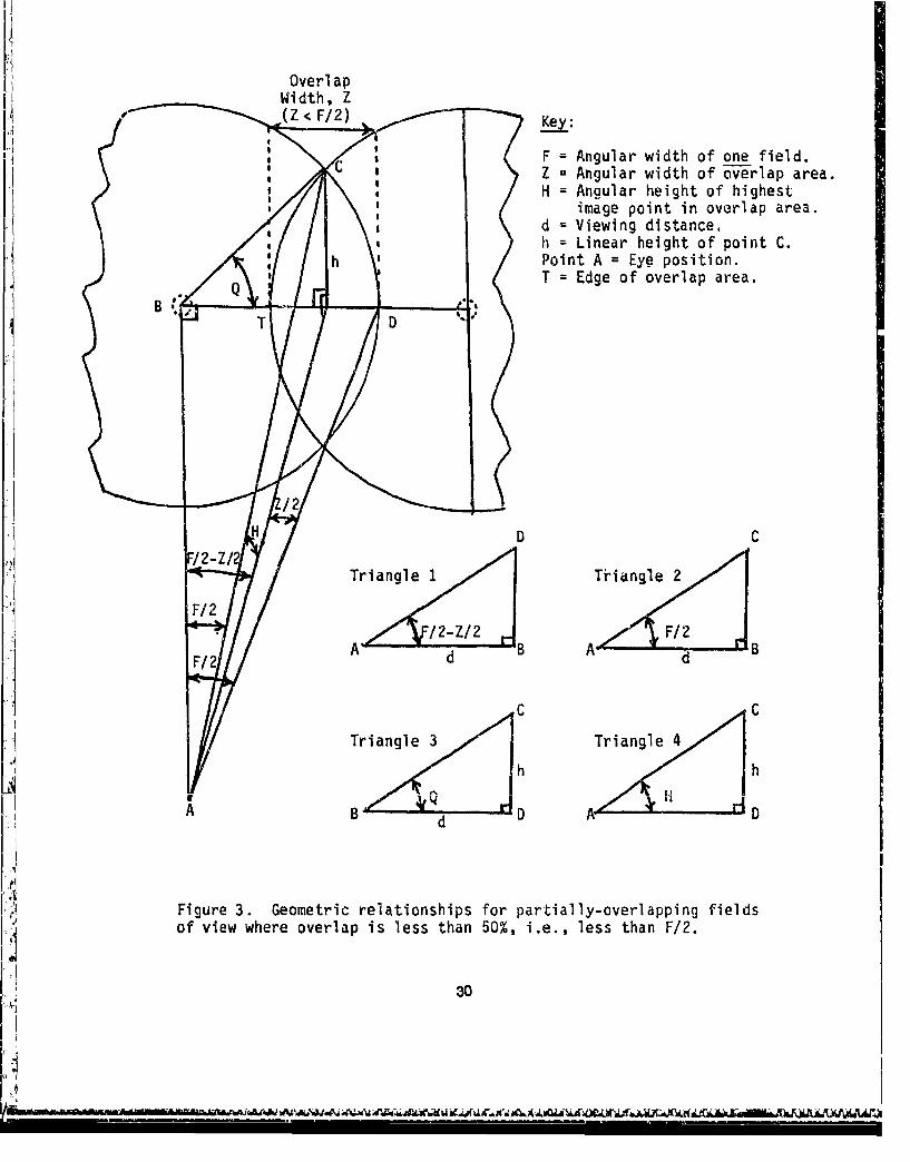
For a field overlap of 50% or less, the geometry of the situation isshown in Figure 3. The maximum image height, H, in the common (oroverlapping) area of the two fields or sides is at the intersection of thefields, at the point labeled "C". The angular height, H, of point "C"clearly increases with F, the FOV of one side, and decreases with decreasingfield overlap. If vertical misalignment, V, is set at some tolerance value,then the maximum permissible magnification difference, K, is smaller forlarge angular fields, F, and is larger for small angular overlap, Z.
Let V be in arc minutes, then, from the discussion above, V/60 -(K/100)H, so that K = 1.667 (V/H). The maximum permissible value of K, asgiven by this equation, is the tolerance for magnification differencecalculated from the tolerance in arc minutes for vertical misalignment andthe image height in degrees. To calculate magnification differencetolerance for a field overlap of 50% or less, one uses the equation for Kand an equation for maximum image height in the overlap (or common) areaderived in Table 5. The two equations to use are:
H = arc Cos Cos(F/2)/Cos(F/2 - Z/2)K = 1.667 (V/H)Where:H = maximum angular height in degrees of the highest common imagepoint in the overlap area.
K = magnification difference tolerance in percent between thetwo sides or fields.
F = total FOV of one side or field.
Z = total field overlap in degrees = angular width of the commonor overlap area.
V = maximum permissible vertical misalignment in minutes ofarc = vertical misalignment tolerance.
29
Overl apWidth, Z
Z < Key:
'I F = Angular width of one field.Z = Angular width of overlap area.H = Angular height of highest
image point in overlap area.d = Viewing distance,h = Linear height of point C.
SPoint A = Eye position.
B rT Edge of overlap area.
" T D "
HD C
STriangle1 Trangle 2
FFf2
A d d
C C
Triangle 3 Triangle 4
I"h h
[I B • DA.d
Figure 3. Geometric relationships for partially-overlapping fieldsof view where overlap is less than 50%, i.e., less than F/2.
30

EXAMPLE OF PROCEDURE
Let FOV = F = 600, Z, or field overlap, be 50%, i.e., Z = 600/2 = 300,and assume a vertical misalignment tolerance of V = 3.4 arc minutes, asrecommended by Gold (1971). Then, H w arc Cos Cos(600/2)/Cos(600/2 - 300/2)= 26.290, and K = (1.667)(3.4/26.29) = 0.216%. Thus, for the conditions of
TABLE 5
MAXIMUM IMAGE HEIGHT* IN OVERLAPPING OR COMMON AREA
Triangle 3 Tan Q = h/BD, Buth = AD Tan H. Substituting h:
Tan Q = AD Tan H/BD = (AD/BD) Tan H, But
Triangle 1 AD/BD = 1/Sin (F/2 - Z/2). Substituting AD/BD:
Eqn. (A) Tan Q = Tan H/Sin (F/2 - Z/2)Triingle 3 h = BD Tan QTriangle 1 BD = d Tan (F/2 - Z/2). Substituting BD:
h = d Tan (F/2- Z/2) Tan Q, or
h/d = Tan (F/2 - Z/2) Tan Q, or
Triangle 4 h = AC Sin H. Substituting h:AC Sin H /d = Tan (F/2 - Z/2) Tan Q, or
AC/d = Tan (F/2 - Z/2) Tan Q/Sin H
Triangle 2 AC/d = I/Cos(f/2). Equating AC/d value
1/Cos(f/2) = Tan (F/2 - Z/2) Tan Q/Sin H.Solving for Tan Q:
Eqn. (B) Tan Q = Sin H/Cos (F/2) Tan (F/2 - Z/2)
Equating Tan Q of equations (A) and (B):
Tan H/Sin (F/2 - Z/2) = Sin H/Cos (F/2)Tan (F/2 - Z/2)
This red- t~ao:4
a
Cos H = Cos (F/2)/Cos (F/2 - Z/2), so that
E.qn(C) H = Arc Cos Cos (F/2)/Cos (F/2 - Z/2)
* The derivation is based on Figure 3.
31
this example, the magnification difference tolerance is less than 1/4 %, arather small amount. This means that there is a tight tolerance on opticalparts: close matching of parts is required, or, with CRTs, precise voltageadjustments are necessary. As a point of interest, with 100% overlap, themaximum value of H is at the top of the field, at 600/2 - 300, and K =(1.667)(3.4)/60/2) = 0.19% maximum permissible magnification difference.
A CAUTIONARY NOTE FOR SMALL FIELD OVERLAP
With small field overlap, magnification difference tolerances should becalculated for both vertical and horizontal misalignment tolerances, and thesmaller of the two should be used. With smal-loverlap, horizontaltolerances may be exceeded when vertical tolerances are met.
As noted earlier in the present paper, observers can tolerateappreciably more horizontal misalignment, W, than vertical misalignment, V.Because of this smaller vertical misalignment tolerance, calculation of themaximum permissible magnification difference is customarily based on notexceeding a specified tolerance for vertical misalignment. However, somebinocular viewing devices have only a small field overlap (or viewing areaconmon to both eyes). This construction is used to obtain a larger totalhorizontal viewing area than possible with completely overlapping fields.
When field overlap is small, an amount of magnification difference thatproduces an acceptable amount of vertical misalignment may produce anunacceptable amount of horizontal misalignment. This point will beillustrated by elaboration of the example presented above that was used toillustrate computation procedure. Note that, in the figure used to derivethe formula for H, the maximum horizontal misalignment produced by amagnification difference would be at the edge of the field, at point "T". Atthis point, horizontal misalignment is W (K/1OO)F degrees, or, in arcminutes, W a (KF/100)(60) = KF/1.667. In the example, with a 600 FOV oneach side of the instrument and a 300 field overlap, the maximum permissiblemagnification difference was 0.216%. This produced a vertical misalignmentat the highest point in the overlapping (or common) viewing area of 3.4 arcminutes, Gold's 1971 tolerance limit.
In the example, the maximum horizontal misalignment produced by amagnification difference of K percent would occur at the edge of the 600field, F, and would be W = 0F/1.667 = (0.2i6)(60)/1.667 = 7.71 arc minutes.This number approaches Gold's 1971 tolerance limit for horizontal
misalignment of 8.6 art. minutes.
As a point of interest, suppose that field overlap in the example was200 instead of 300. Then, H = arc Cos Cos(60o/2)/Cos(60o/2 - 200/2) =
22.80, and K = (1.667)(3.4)/22.8 - 0.249% maximum permissible magnificationdifference based on 3.4 arc minutes tolerance for vertical misalignment. Inthis case, horizontal misalignment at the edge of the overlapping area is W
KF/1.667 = (0.249)(60)/1.667 = 8.96 arc minutes. Gold (1971) reconmmends a,,e maximum of 8.6 arc minutes of horizontal misalignment. Thus, while the
vertical misalignment tolerance of 3.4 arc minutes is not exceeded by using
32

a K of .249%, the horizontal tolerance of 3.4 arc minutes has been exceeded.Not to exceed the horizonal misalignment tolerance would require that W =8.6 - (K)(60)/1.667, from which maximum permissible magnification differencewould be K - (8.6)(1.667)/60 = 0.239%, not 0.249%.
This example shows that a magnification difference that does notproduce an unacceptable vertical misalignment may produce an unacceptablehorizontal misalignment. When field overlap Is small, then, tolerances formagnification differences should be calculated based on both vertical andhorizontal misalignment tolerances. The numerically smaller of the two Kvalues should be used.
33
33
IE|1
REFEREMCES
Anonymous (5 Oct 1962). MIL-HDBK-141, Military Standardization HandbookOptical Design. Defense Supply Agency, Washington 25, D.C., pages 16 -18"of section 4.
Anonymous (1966). Optical man 382. Bureau of Naval Personnel. NavyTraining Course NAV Pers 10205. For sale by the Superintendent ofDocuments, U.S. Government Printing Office, Washington D.C., 20402.
Anonymous (2 May 1981). MIL-STD-1472C, Military Standard, Human EngineeringDesign Criteria for Military Systems, Equipment, and Facilities.Department of Defense, Washington, D.C. 20301, pages 209 and 211.
Farrell, R.J., Anderson, C.D., Kraft, L.L., and Boucek, G.P., Jr. (1970).Effects of convergence and accommodation on stereopsis. Document D180-19051-1 and D180-19051-2. The Boeing Co., Seattle, Washington (citedwith graph of data, in Farrell & Booth, 1984).
Farrell, R.J. and Booth, J.M. (1984). Design handbook for imageryinterpretation equipment. Boeing document D180-19063-1 (reprint, withcorrections, of 1975 original). Boeing Aerospace Company, Seattle,Washington 98124.
Genco, L.V. (1983). Optical interactions of aircraft windscreens and HUDsproducing diplopia. Reported in Martin, Wayne L. (Editor), 0ptical andHuman Performance Evluation of HUD System Design. AFAMRL-TR-83-095,ASD (ENA)-TR-83-5019, Air Force Aerospace Medical Research Laboratory,Aerospace Medical Division, Air Force Systems Command, Wright-PattersonAir Force Base, Ohio 45433-6573 (ADA 140 601).
Gibson, C.P. (1980). Binocular disparity and head-up displays. HumanFactors, 1980, 22(4), 435-444.
Gold, T. (1971). Visual disparity tolerances for head-up displays.Electro-Optical System Design Conference 1971 West, Anaheim, CA(published by Industrial and Scientific Conference Management, Inc.222 West Adams Street, Chicago, IL 60606)1. Pages 399-406.
Gold, T. and Hyman, A. (1970). Visual requirements for head-up displays,final report, Phase 1. JANAIR Report 680712. Speery-Rand Corp.,prepared for Office of Naval Research, 1970 (available from NTIS or DDCas AD 707 128).
Harvey, L.O., Jr., (1970). Research Paper P-453. Survey of visual researchliterature on military problems during World War II. (Papers collectedby the Armed Forces - NRC Vision Connittee). Institute of DefenseAnalysis, Science and Technology Division, 400 Army-Navy Drive,Arlington, VA, 22202.
34

Hertzberg, H.T.E., Daniels, G.S., an Churchill, E. (1954). Anthoropometryof Flying Personnel - 1950. WADC TR-52-321, Wright Air DevelopmentCenter, Wright-Patterson Air Force Base, Ohio, 45433 (AD 047 953).
Ingalls, A.L. and Pestrecov, K. (Apr 1948). Centering of optical systems.Journal of the Optical Society of America, Vol. 38, No. 4, pages 343-349.
Jacobs, D.H. (1943). Fundamentals of Optical Engineering. McGraw-Hill BookCo., Inc. New York, NY, pages 211-213.
Johnson, B.K. (1948). Optics and Optical Instruments. Dover Publications,Inc., New York, NY, pages 70-73.
NOTE: To order documents from the U.S. Government, give AD Number (listedTn parenthesis), if available, and order from:
NTISNational Technical Information ServiceU.S. Department of CommerceSpringfield, VA 22161
I :I
I.A
!IJ
35 , GOERNMENT PNTiNQOFF". IM - U4-006/40209
'I[1